

Page 1

4#,
ĂĂĂĂĂĂĂĂĂĂĂĂĂĂĂĂĂĂĂĂĂĂĂĂĂĂĂĂ
ĂĂĂĂĂĂĂĂĂĂĂĂĂĂĂĂĂĂĂĂĂĂĂĂĂĂ
ĂĂĂĂĂĂĂĂĂĂĂĂĂĂĂĂĂĂĂĂĂĂ
ĂĂĂĂĂĂĂĂĂĂĂĂĂĂĂĂĂĂĂĂĂĂĂĂĂ
ĂĂĂĂĂĂĂĂĂĂĂĂĂĂĂĂĂĂĂĂĂĂĂ
ĂĂĂĂĂĂĂĂĂĂĂĂĂĂĂĂĂĂĂĂĂĂĂĂ
ĂĂĂĂĂĂĂĂĂĂĂĂĂĂĂĂĂĂĂĂĂĂĂĂĂ
3%26)#%-!.5!,
#AUTIONĂ
SPECIFICATION
!LIGNMENT0ROCEDURE
ˊ"LOCKDIAGRAM
ˊ3CHEME$IAGRAM
4ROUBLESHOOTING
0#",AYOUT
4HISM ANUALI ST HEL ATESTAT T HET IMEOF PR INTING ANDDOE S NOT
INCLUDETHEMODIFICATIONWHICHMAYBEMADEAFTERTHEPRINTINGBY
THECONSTANTIMPROVEMENTOFPRODUCT
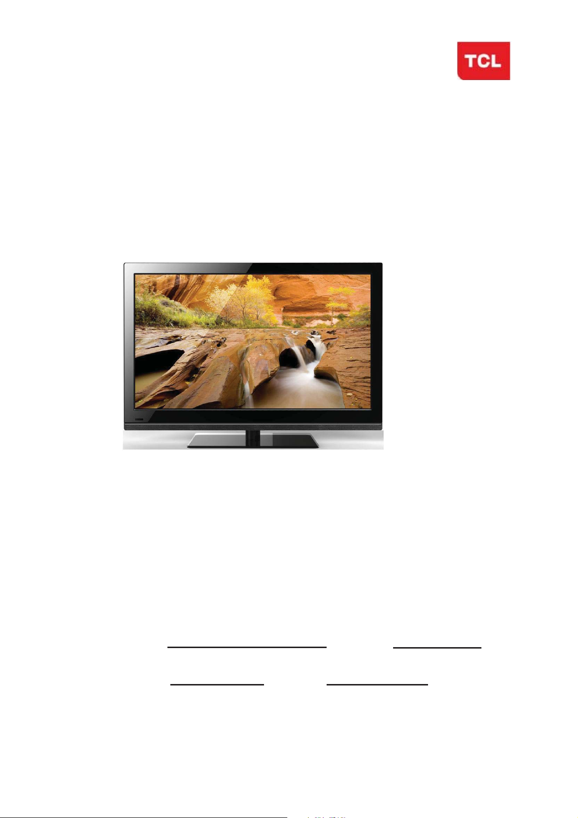
L32E5300/MT27S-AP/CSTM E3 V
Page 2

RISK OF
ELECTRIC
SHOCK DO
NOT
OPEN.
SCHNEIDER ELECTRONICS GMBH-GERMANY
1. CAUTION
CAUTION:
Use of controls, adjustments or procedures other than those specified herein may result in
hazardous radiation exposure.
CA UTION : TO RE DUCE THE RIS K OF
CA U T IO N
RISK
SHOCK
The lighting flash with arrowhead symbol, with an equilateral triangle is intended to
alert the user to the presence of uninsulated voltage within the product s
enclosure that may be of sufficient magnitude to constitute a risk of electric shock to
the person.
The exclamation point within an equilateral triangle is intended to alert the user to the
presence of important operating and maintenance (servicing) instructions in the
literature accompanying the appliance.
ELECTRI
NOT
OPEN.
ELECTR ICAL SHOC K, DO NOT RE MOVE
COVER (OR BACK). NO USER SERVIC EABLE
PAR TS INS IDE . RE FER SE R VICING TO
QUALIFIE D SERVIC E PE RS ONNEL.
dangerous
WARNING: TO REDUCE RISK OF FIRE OR ELECTRIC SHOCK, DO NOT
EXPOSE THIS APPLIANCE TO RAIN OR MOISTURE.
2
2
Page 3

SCHNEIDER ELECTRONICS GMBH-GERMANY
IMPORTANT SAFETY INSTRUCTIONS
CAUTION:
Read all of these instructions. Sa ve these instructions for later use . Follo w all W arnings and
Instructions marked on the audio equipment.
1. Read Instructions-All the safety and operatinginstructionsshouldbe read beforethe productis operated.
2. Retain Instructions- The safety and operating instructions should be retained for future reference.
3. Heed Warnings- All warnings on the product and in the operating instructions should be adhered to.
4. Follow Instructions- All operating and use instructions should be followed.
FOR YOUR PERSONAL SAFETY
1. When the power cord or plug is damaged or frayed, unplug this television set from the wall outlet and refer servicing to
qualified service personnel.
2. Do not overload wall outlets and extension cords as this can result in fire or electric shock.
3. Do not allow anything to rest on or roll over the power cord, and do not place the TV where power cord is subject to
traffic or abuse. This may result in a shock or fire hazard.
4. Do not attempt to service this television set yourself as opening or removing covers may expose you to dangerous
voltage or other hazards. Refer all servicing to qualified service personnel.
5. Never push objects of any kind into this television set through cabinet slots as they may touch dangerous v oltage
points or short out parts that could result in a fire or electric shock. Never spill liquid of any kind on the television set.
6. If the television set has been dropped or the cabinet has been damaged, unplug this television set from the wall outlet
and refer servicing to qualified service personnel.
7. If liquid has been spilled into the television set, unplug this television set from the wall outlet and refer servicing to
qualified service personnel.
8. Do not subject your television set to impact of any kind. Be particularly careful not to damage the picture tube surface.
9. Unplug this television set from the wall outlet before cleaning. Do not use liquid cleaners or aerosol cleaners. Use a
damp cloth for cleaning.
10.1. Do not place this television set on an unstable cart, stand, or table. The television set may fall, causing serious injury
to a child or an adult, and serious damage to the appliance. Use only with a car t or stand recommended by the
manufacturer, or sold with the television set. Wall or shelf mounting should follow the manufacturer s instructions, and
should use a mounting kit approved by the manufacturer.
10.2. An appliance and cart combination should be moved with care. Quick stops, excessive force, and uneven surfaces
may cause the appliance and cart combination to overturn.
3
3
Page 4
SCHNEIDER ELECTRONICS GMBH-GERMANY
PROTECTION AND LOCATION OF YOUR SET
11. Do not use this television set near water ... for example, near a bathtub, washbowl, kitchen sink, or laundry tub, in a
wet basement, or near a swimming pool, etc.
Never expose the set to rain or water. If the set has been exposed to rain or water, unplug the set from the wall
outlet and refer servicing to qualified service personnel.
12. Choose a place where light (artificial or sunlight) does not shine directly on the screen.
13. Avoid dusty places, since piling up of dust inside TV chassis may cause failure of the set when high humidity persists.
14. The set has slots, or openings in the cabinet for ventilation purposes, to provide reliable operation of the receiver, to
protect it from overheating. These openings must not be blocked or covered.
Never cover the slots or openings with cloth or other material.
Never block the bottom ventilation slots of the set by placing it on a bed, sofa, rug, etc.
Never place the set near or over a radiator or heat register.
Never place the set in enclosure, unless proper ventilation is provided.
a built-in
PROTECTION AND LOCATION OF YOUR SET
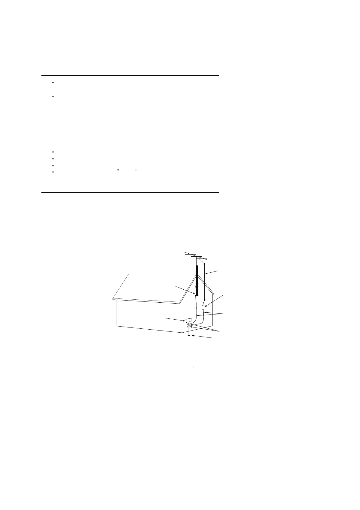
15.1. If an outside antenna is connected to the television set, be sure the antenna system is grounded so as to provide some
protection against voltage surges and built up static charges, Section 810 of the National Electrical Code, NFPA No.
70-1975, provides information with respect to proper grounding of the mast and supportingstructure, grounding of the
lead-in wire to an antenna discharge unit, size of grounding conductors, location of antenna discharge unit, connection
to grounding electrode, and requirements for the grounding electrode.
EXAMPLE OF ANTENNA GROUNDING AS PER NATIONAL ELECTRICAL CODE INSTRUCTIONS
EXAMPLE OF ANTENNA GROUNDING AS PER
NATIONAL ELECTRICAL CODE
ANTENNA
LEAD- IN WIRE
GROUND CLAMP
ELECTRIC SERVICE
EQUIPMENT
NEC-NATIONAL ELECTRICAL CODE
ANTENNA DISCHARGE
UNIT (NEC SECTION
810-20)
GROUNDING
CONDUCTORS
(NECSECTION 810-21)
GROUND CLAMPS
POWER SER VICE GROUNDING
ELECTRODE SYSTEM
(NEC ART 250. PART H)
15.2. Note to CATV system installer : (Only for the television set with CATV reception)
This reminder is provided to call the CATV system attention to Ar ticle 820-40 of the NEC that provides
installer s
guidelines for proper grounding and, in particular, specifies that the cable ground shall be connected to the grounding
system of the building, as close to the point of cable entry as practical.
16. An outside antenna system should not be located in the vicinity of overhead power lines or other electric lights or power
circuits, or where it can fall into such power lines or circuits. When installing an outside antenna system, extreme care
should be taken to keep from touching such power lines or circuits as contact with them might be fatal.
17. For added protection for this television set during a lightning storm, or when it is left unattended and unused for long
periods of time, unplug it from the wall outlet and disconnect the antenna. This will prevent damage due to lightning
and power-line surges.
4
4
Page 5

SCHNEIDER ELECTRONICS GMBH-GERMANY
OPERATION OF YOUR SET
18.
This television set should be operated only from the type of power source indicated on the marking label.If you are not
sure of the type of power supply at your home, consult your television dealer or local power company. For television
sets designed to operate from battery power, refer to the operating instructions.
19. If the television set does not operate normally by following the operating instructions, unplug this television set from the
wall outlet and refer servicing to qualified service personnel. Adjust only those controls that are covered in the operating
instructions as improper adjustment of other controls may result in damage and will often require extensive work by a
qualified technician to restore the television set to normal operation.
20. When going on a holiday : If your television set is to remain unused for a period of time, for instance, when you go on
a holiday, turn the television set and unplug the television set from the wall outlet.
off
IF THE SET DOES NOT OPERATE PROPERLY
21. If you are unable to restore normal operation by followingthe detailed procedurein your operatinginstructions,
do not attempt any further adjustment. Unplug the set and call your dealer or ser vice technician.
22. Whenever the television set is damaged or fails, or a distinct change in performance indicates a need for
service, unplug the set and have it checked by a professional service technician.
23. It is normal for some TV sets to make occasional snapping or popping sounds, particularly when being
turned on or off. If the snapping or popping is continuous or frequent, unplug the set and consult your
dealer or service technician.
FOR SERVICE AND MODIFICATION
24. Do not use attachments not recommendedby the television set manufacturer as they may cause hazards.
25. When replacement parts are required, be sure the service technician has used replacement parts specified
by the manufacturer that have the same characteristics as the original part. Unauthorized substitutions
may result in fire, electric shock, or other hazards.
26. Upon completion of any service or repairs to the television set, ask the ser vice technician to perform
routine safety checks to determine that the television is in safe operating condition.
5
5
Page 6
EM BUSINESS CENTER
䌒ᔎ
FTV PRODUCT MANAGEMENT DEPT.
SPECIFICATION RELEASE
Version: V1.0 Issued Date: 2012.8.8
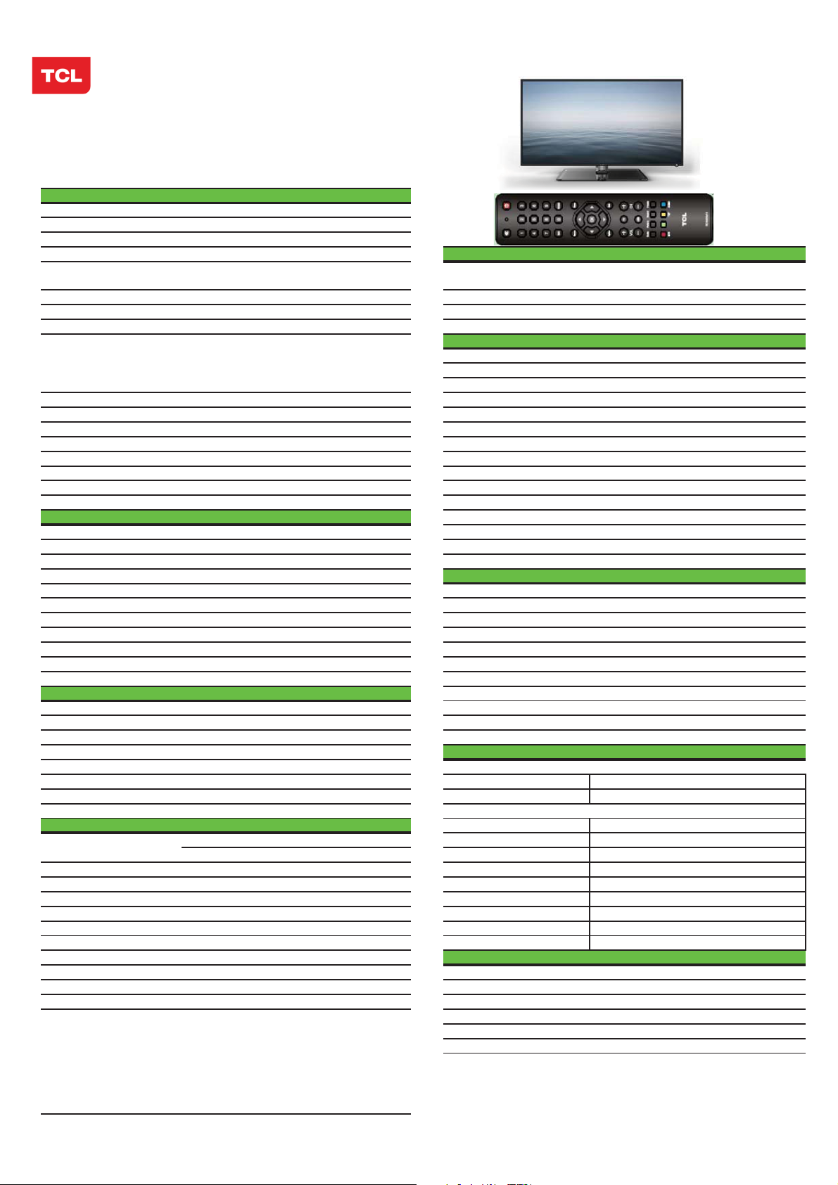
Model:
L32E5300/MT27S-AP/CSTM E3
PICTURE
Category
Dynamic Contrast Yes
Color Temperature Warm / Standard/ Cool
Backlight Adjustable Yes
Scale Mode
Picture Effect Standard, Bright, Soft, User DVI Video Format Up to XGA for HDMI-PC
Film Mode (3:2 pull down) AUTO HDMI Video Format up to 1080P
VGA Dot to Dot D isplay Yes (Natural) PC Compatibility Up to SXGA
Light Sensor
LCDTV
SIGNAL FORMAT CAPABILITY
Standard,Full, Subtitle, Wide Screen,
Zoom,Expand,Original,Natural Component Video Format Y,PB/CB,PR/CR:up to 1080P
ON/OFF. When set to ON,TV can automatically
adjust the backlight according to the intensity of
ambient light,and it is in power saving mode. AV2 Input (Co mposite)
TERMINALS
AV1 Input (Co mposite)
Audio/CVBS---R/L+ Video in side
Video Share with Y
and Audio share with YP
BPR Audio
Picture Enhancement YPBPR Input 1---Downward
Comb Filte r 3D Audio Input for YP
Adaptive Deinterlacing 3D YC
Blue Stretch Yes Audio Input for YC
Black Stretch Yes VGA(PC ) Input 1 (D-Sub,1 5 Pins)---Downward
DLTI Yes Audio Input for V GA(PC) Share with Audio for "YP
DCTI Yes HDMI 1 ---downward
Dynamic Skin Correction Yes
PANEL SPECIFICATION
Back light Unit
Panel supplier TCL RF Input(A ntenna) 1 (IEC Type)---Downward
Aspect Ratio 16:9 USB 1˄Standard˅---side
Panel Size (inch) 32"
Display Resolution 1366*768 TV System PAL/SECAM B/G,D/K,I ;NTSC-M
Brightness (cd/m2) 300 AV System
Contrast Ratio 4000:1 Channels
Response Time Tr/Tf 6.5ms Chassis
Viewing Angle (H/V) 178°/178° Certification
Life Time 30,000hrs Power Supply
Color 16.7M Power Consumption-TV on
LED Headphone Output N o
SOUND
Speakers Integrated speakers (Bottom) Default Color of Front Cabinet
Audio Power Output 2×8W Keyboard Position
Woofer Power Output -- Base Stand Detachable
Smart Volume Yes
Sound Effect Stereo, Movie, News, User Unpackaged Dimension for Main Body (L*H*D) (mm)
Sound Control
Sound Fea tures
Balance, Bass, Treble With Base Stand (mm) 730.5*183*494
MTS˄NICAM˅ Without Base Stand (mm) 730.5*60.5*439.1
Scene Selecting˄Desk Top mode and Hang Up mode˅
FUNCTION
OSD Language English/French/Thai/Vietnamese/Russia n Speaker Box
Portuguese/Arabic//F arsi/He brew/Mongolian Base Stand
OSD Features Motion Bmp Style Net Weight (Kg)
Teletext Yes Gross Weight (Kg)
Clock/Sleep Timers Yes
Wake up/Turn off time Yes 20 feet
Wake up Source/C hannel Yes 40 feet
Watch Time Limit Yes 40 feet high
Smart Switch Yes(Signal Auto Detecting and Changing Source)
Picture Freeze Yes Operation Manual English(Default)
DNR˄Dynamic Noise Reduction˅ OffǃLowǃstandard ǃstrong Remote C ontrol For TV control (with two batteries)
Hotel Menu In factory mode Base Stand
USB Connection
Movie˖Support H .264ǃRM/RMVB, Speaker Box
MPEG2ǃMPEG4,etc. Wall Mount
Photo: Suppo rt JPEGǃBMP Others AC Power cord
Music: support MP3
BCR Input Share with "Y PBPR"
CVBS Video Output (Composite)
CVBS Audio Output
BASIC INFO.
Power Consumption-Standby
PACKAGE INFO.
Packaged Dimension (L*H*D)
Main Body (mm)
Container Loading
ACCESSORIES
Drafted by:
Note: For coding files, there are many kinds of no-standard coding method. So this system
can not be guaranteed to support the file formats using any coding method.
Checked by:
BPR 1---Downward
BCR Share with Audio for "YPBPR"
BPR"
1 RCA video socket,Downward
1 3.5mm socket--Side
PAL,NTSC,SECAM
199(1~199)
MT27S-AP
CB
AC 100V-240V 50/60Hz
70W
İW
Black
Side
Yes
878*184*566
--
--
8.3(With Base Stand)
10
328
676
785
Integrated Packaging
No
WME300˄Optional˅
Design and specifications are subject to change without notice!
Approved by:
Page 7
TCL Multimedia Technology Holdings Ltd.
R&D Center
Alignment Procedure
MT27S-AP/LA Chassis
Version: 1.0
Release Date: 2012-4-16
PREPARED BY: SHU XIANG CHENG
APPROVED BY:
DATE:
DATE: 2012-4-16
Page 8
MT27S-AP/LA Chassis Aliment procedure
Content
1. General Description 3
2. Factory Menu 3
2.1 Way of accessing 3
2.2 Factory Menu 4
2.3 White Balance adjustment 5
3. DesignMenu1 6
4. DesignMenu2 7
4.1 HOTEL MENU 7
4.1.1 Accessing way 8
5. Steps of debugging 9
5.1 device 9
5.2 Steps of debugging 9
5.3 WB adjustment 9.10
6. Chip list of software programming before SMT 11
7. Appendix 11
7.1 Software upgrading through USB 11
7.2 Check software version, release date and Project ID 12.13
7.3 FAQ 14
History Description of major changes Release
Date
V1.0 2012-4-16
Chassis Model
FHD
HD MT27S-APLA L32D3260, etc
PRELIMINARY INFORMATION ----- SUBJECT TO CHANGE
2
Page 9
MT27S-AP/LA Chassis Aliment procedure
1. General Description
MT27S-AP/LA is our latest design especially for LCDTV products selling in Asia
Pacific (AP) and Latin America (LA) market. It features by its high integration,
easy debugging as well as convenience in terms of maintenance. Fast software
upgrade through USB disk facilitates both manufacture and after-sale service.
Meantime, a variety of functions involved in Factory Main Menu can not only
bring benefits for production, but also satisfy various demands of customer.
Note: Factory Menu covers all indispensable functions during manufacture such as
White Balance Adjustment, Shop Init, NVM Reset,DesignMenu1,DesignMenu2 e.g.,
while the items under DesignMenu1 and DesignMenu2 is exclusively used by R&D
engineer, anyone else shouldn’t change the settings in the menu. When you wish to
learn the product information like project ID, model name, you can access to
DesignMenu1. In addition, in Hotel Menu, we also provide a great deal of useful
functions for specific applications in hotel.
2. Factory Menu
2.1 Accessing way:
a. In the first place, press Menu
button of remote control, then select
Contrast item of Picture submenu.
Finally, press 9, 7, 3, 5 consecutively.
b. When the FAC HOTKEY item of
Factory Menuis enabled (ON), press
Return button of remote control.
PRELIMINARY INFORMATION ----- SUBJECT TO CHANGE
3
Page 10
MT27S-AP/LA Chassis Aliment procedure
ˈ
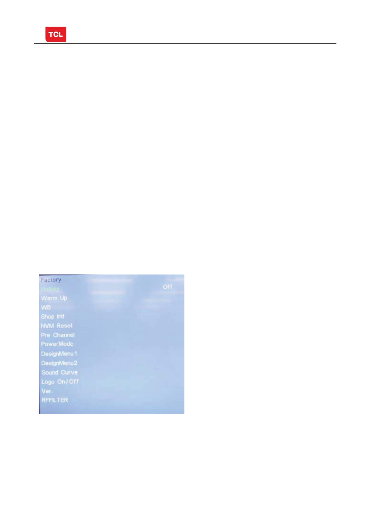
2.2 Factory Menu
Factory Menu
Name Default Description Status
HOTKEY OFF Factory Menu shortcut button switch
The item must be disabled (OFF) after production
WARM- UP OFF OFF: Normal mode. Display blue screen when no signal. Turn to
automatically standby mode if keep the signal unavailable over
15 minutes.
ON: Aging mode. Display Red
signal. The set will not turn to standby even if the unavailability of
signal, Press MENU of KEY TO exit
WB >> White Balance Adjustment ( see details below) OK
SHOP Init DO It is crucial that the function is executed after production aim to clear
information of production process, ensure user cannot access to
Factory Menu after executing the item.
NVM RESET DO Restore default value except WB OK
Pre Channel DO Preset the channel table of factory. Option: HZ, WX, NMG, ORION e.g.
To preset the channel table of certain factory, firstly, choose the
corresponding factory name, then press OK button of remote control
and wait until the disappearance of Factory Menu,
PowerMode LAST/STB ON: the set will power on after switching on power.
STB: the set will remain standby status after switching on power.
BlueˈGreenˈWhite Scene when no
OK
OK
OK
OK
OK
Last: the set will turn to the status in which it lies when last switching
off.
If without requirement from certain customer,
by default, the Setting should be Last for MT27S-AP and STB for
MT27S-LA
DesignMenu1 DO exclusively used by R&D engineer OK
DesignMenu2 DO exclusively used by R&D engineer OK
Sound Curve DO
Logo ON/OFF DO
Exclusively used by R&D.
Display TCL Logo or not. On : display,
OK
OK
Off: not display
VER. DO
RFFILTER
software version, release date e.g.,
Exclusively used by R&D.
OK
ok
PRELIMINARY INFORMATION ----- SUBJECT TO CHANGE
4
Page 11
MT27S-AP/LA Chassis Aliment procedure
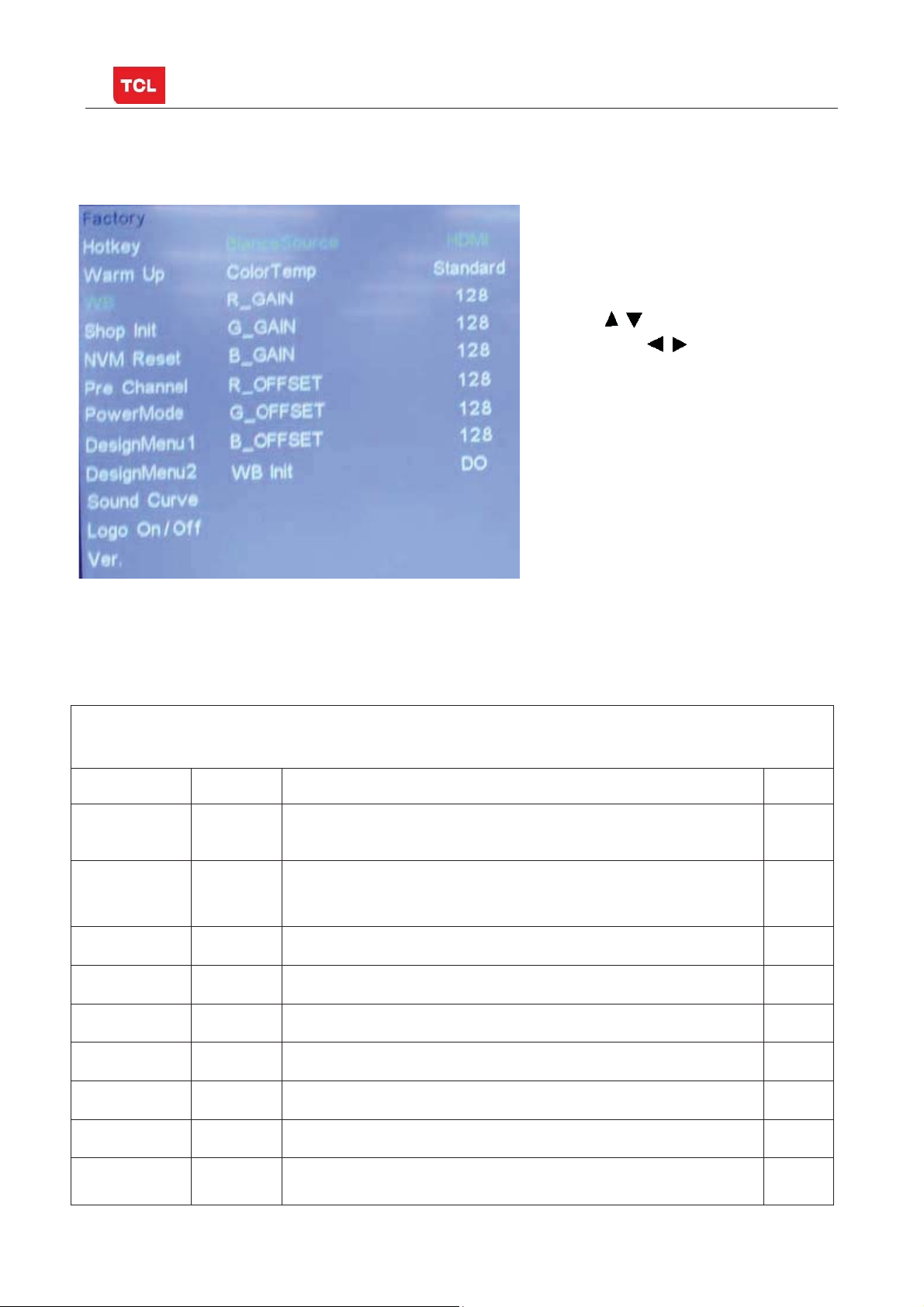
2.3 White Balance Adjustment menu
White Balance menu
Press the button in remote control to select
certain item and
to adjust White Balance
White Balance Adjustment menu
Name Default Description Status
BlanceSource AV1 Select the source you intend to apply WB adjustment.
Only HDMI1, AV1, YPBPR, PC and should be adjusted.
ColorTemp
R GAIN
G GAIN
B GAIN
R OFFSET
G OFFSET
B OFFSET
WB INIT
Standard Select color temperature you intend to adjust Three groups of
color temperature: Normal, Warm, Cool are available for each
source.
+2
0
-7
0
0
0
Gain of R channel ( cannot be changed after auto calibration) OK
Gain of G channel ( cannot be changed after auto calibration) OK
Gain of B channel ( cannot be changed after auto calibration) OK
Sw Default ,NOT need calibration OK
Sw Default ,NOT need calibration OK
Sw Default ,NOT need calibration OK
White Balance Initalization. Before WB adjustment, this item should
be executed.
PRELIMINARY INFORMATION ----- SUBJECT TO CHANGE
OK
OK
OK
5
Page 12

3. DesignMenu1
MT27S-AP/LA Chassis Aliment procedure
Press the button in remote
control to select certain item and
to toggle among or execute
the available options.
DesignMenu1
Name Default Description Status
Initvol 25 Exclusively used by R&D. OK
TunerAGC 0 Exclusively used by R&D. OK
ProjectID
PrintMessage OFF Exclusively used by R&D. OK
Descramble
box
Descramble
box
Sound_Count 0 Exclusively used by R&D. OK
DBC 0 Parameter of DBC
DB_CP 100 Exclusively used by R&D. OK
OFF Exclusively used by R&D. OK
OFF Exclusively used by R&D. OK
the product information like project ID, model name
Exclusively used by R&D.
OK
OK
PRELIMINARY INFORMATION ----- SUBJECT TO CHANGE
6
Page 13

MT27S-AP/LA Chassis Aliment procedure
˄
˅
DBC_BP 60 Exclusively used by R&D OK
Spread Step 30 LVDS Spread expand
Exclusively used by R&D
OK
4 DesignMenu2
Press the
select certain item and
among the available options..
button in remote control to
to toggle
DesignMenu2
Name Default Description Status
Panel_control on Exclusively used by R&D OK
Panel_freq 30 Exclusively used by R&D OK
Panel_percent 5 Exclusively used by R&D OK
bluemute on Exclusively used by R&D OK
Otherct1 on Exclusively used by R&D OK
FleshTone on Exclusively used by R&D OK
LumaControl on Exclusively used by R&D OK
Hotel Menu
enable
USB UPG
PRELIMINARY INFORMATION ----- SUBJECT TO CHANGE
off
Hotel Menu is accessible only when HOTEL Menu
(enable) item is enabled (ON).
Upgrade software. Please see details below.
OK
OK
7
Page 14

MT27S-AP/LA Chassis Aliment procedure
BackIT off Exclusively used by R&D ok
4.1 HOTEL MENU
4.1.1 Accessing way:
a. Hotel Menu(enable)item is enabled(on)
b. press Menu button of remote control,
then select
Contrast item of Picture submenu.
Finally, press 9, 7, 1, 5 consecutively.
Name Default Description Status
HOTEL MENU
POWER
LOGO
CH LOCK OFF Channel scan lock. OK
MAX VOL 100 Max volume OK
AUTO SET OFF The switch of PIC, SOUND etc.
PIC MODE user Picture mode. OK
SOUND
MODE
POWER
VOL.
POWER
SIGNAL
POWER
CHANNEL
KEY LOCK OFF Lock the keys. OK
SAVE DATA
TO USB
ON LOGO select OK
OK
When it is ON, these items are selectable.
user Sound mode OK
25 Default volume when power on OK
TV Default signal source when power on OK
1 Default channel no. when power on OK
DO Save the settings of TV to USB OK
PRELIMINARY INFORMATION ----- SUBJECT TO CHANGE
8
Write Data
from USB
DO Copy the settings of USB TO TV OK
Page 15

MT27S-AP/LA Chassis Aliment procedure
g
p
g
ging
˖
5. The steps of debuggin
5.1 Device
Color Analyzer CA-210. Video Pattern Generator Chroma2329. Color TV Pattern
Generator PM5418, VGA cable, AV cable(RCA),YPBPR(RCA) cable.
DŽ
Chroma2329
5.2 ste
s of debu
Fluke5418 CA-210
According to the requirement of order, we suggest take the below steps to finish
the appropriate settings.
A enter the Factory Menu, enable HOTKEY
B Check the version of software, release date displayed at the bottom of Factory
Menu. If the information is correct, you can ignore step C and D.
C Enter Factory Menu, choose DESIGNMENU1->PROJECT ID, choose corresponding
Project ID number of the product (Please refer to the description in BOM about
Project ID number).
D return to DesignMenu1, check the Product model.
E choose Factory Menu-> NVM RESET and press
and wait until prompt OK
appears.
F restart the set
G according to the requirement of order, set the items of Hotel Menu etc.
H After aging under normal temperature, adjust white balance.
I choose Factory Menu-> SHOP INIT and press
button of remote control to
initialize the set.
Note: after step I (execute SHOP INIT), Hotel Menu will be disabled by default.
Therefore, if order requires hotel function, it is necessary to enable hotel function by
Factory Menu-> DesignMenu2->HOTEL MENU ENABLE to ON.
set
5.3 White Balance adjustment (Manual)
Before adjustment, you must ensure Color Analyzer has been calibrated. Only AV1,
YPBPR, VGA , HDMI 1 need to be adjusted. It is necessary to adjustment HDMI 1
firstly.
a. signal and generator
The pattern of the signal should be used are White (Chroma2329 pattern113) and
Grey (pattern 114).The format of signal are respectively 720p for HDMI1
(Chroma2329 Timing 69), NTSC for AV1 (Chroma2329 Timing 37),1024×768@60Hz
PRELIMINARY INFORMATION ----- SUBJECT TO CHANGE
9
Page 16

MT27S-AP/LA Chassis Aliment procedure
(Chroma2329 Timing 14) for VGA and 720p (Chroma2329 Timing 79)for YPBPR
b. steps of adjustment
1) enter the factory menu->WB, select source HDMI 1 and COLORTEMP normal.
2) input white signal in 720p format
3) change R Gain and B Gain to make sure the value of color coordination equal to
(x, y).
In addition to select COLORTEMP COOL/WARM, the adjustment method of COOL
and WARM color temperature is same with that of NORMAL. The color coordination
we recommend is as follows:
Device˖CA-210˗ Accuracy˖±0.015
Color Temperature
x
LCD
y
x
LED
y
WARM NORMAL COOL
0.300 0.280 0.270
0.305 0.290 0.270
0.302 0.282 0.272
0.317 0.302 0.282
PRELIMINARY INFORMATION ----- SUBJECT TO CHANGE
10
Page 17

MT27S-AP/LA Chassis Aliment procedure
HDMI White Balance adjustment
6. Chip list of software programming before SMT
Following chip must be programmed before SMT by ALL-11 or other tools.
Position Chip type Chip name Part number Software
1 U401 Flash
W25Q32 13-W25Q32-BVB
description
Main
software;HDMI
KEY;EDID
Decal
SO-8
Note:
1) The software for U401 can be program using ISP tool.
2) Every set has its unique HDCP key which is purchased from suppliers or HDCP
certification authority. Please check HDCP function in the process of production.
3) Once in a while, the software of main board may be upgraded. Please pay attention to
use the latest software before production.
Appendix:
1. Software upgrade through USB disk
1) Please ensure the software you are using has a correct file name
TCL_MT27_UPDATE.bin, then copy it to the root directory of a USB disk.
2) Insert the USB disk to the USB socket of the set for which you are
going to upgrade program.
3) Enter the Factory Menu (you can choose either a or b way below)
a. In the first place, press Menu button of remote
control, then select Contrast item of Picture
submenu. Finally, press 9, 7, 3, 5 consecutively.
b. When the Factory hotkey item of Factory Menu
is enabled (ON), press Return button of remote control.
4) select USB UPG item of DesignMenu2 submenu, press
menu
will appear prompting whether start upgradeor not. Press Yes to start upgrade,
PRELIMINARY INFORMATION ----- SUBJECT TO CHANGE
buttonof remote control, a pop
11
Page 18

MT27S-AP/LA Chassis Aliment procedure
press No to canel. Please wait patiently until the set restart automatically after
upgrade. Do not cut off the power supply during the process.
2. Check software version, release date and Project ID
After upgrading, sometimes you may not certain whether the new software has
been successfully updated or not. In this case, you can check the software version
and release date in Factory Menu to make sure the success of upgrading.
In addition, for the convenience of software management, many models of same
chassis may share a same software, but are allocated with different Project ID.
In another words, every model has its unique Project ID. Obviously, Both software
version and Project ID are highly critical to ensure the set work properly. Therefore,
after upgrading software,we suggest you check these information by following
method.
1) Enter the Factory Menu(you can choose either a or b way below
a In the first place, press Menu button of remote control, then select Contrast item
of Picture submenu. Finally, press 9, 7 3, 5 consecutively.
b. When the HOTKEY item of Factory Menu is enabled (ON), press Return button of
remote control.
2) Check the version of software, release date displayed at the bottom of Factory
Menu. If the information is correct, you can ignore step 3.
3) choose DesignMenu1->PROJECTID, choose corresponding Project ID number of
the product (Please refer to the description in BOM about Project ID number).
4) choose Factory Menu and press OK button of the remote. Next, select NVM RESET
and press
5) choose SHOP INIT and press
Note: after step I (execute SHOP INIT), Hotel Menu will be disabled by default.
and wait until prompt OK appears.
button of remote control to initialize the set.
PRELIMINARY INFORMATION ----- SUBJECT TO CHANGE
12
Page 19

MT27S-AP/LA Chassis Aliment procedure
Therefore, if order requires hotel function, it is necessary to enable hotel function by
Factory Menu-> DesignMenu2->HOTEL Menu enable to ON.
set
6) restart the set.
Product
Information
Change project ID
Project ID
PRELIMINARY INFORMATION ----- SUBJECT TO CHANGE
13
Page 20

MT27S-AP/LA Chassis Aliment procedure
3. FAQ
1) Why there is no picture after upgrading software or changing project ID?
It may be caused by fault of project ID. You can try below method to fix
the problem.
a. If the resolution of the panel of your set is 1366×768(HD panel), you can press
062598,Menu, and Number(HD panel projectID) of remote control in series after
turning on.
b. If the resolution of the panel of your set is 1920×1080(FHD panel), you
can press 062598,Menu, and Number(FHD panel projectID) in series after
turning on.
c. If you can see the picture at this time, please recheck the project ID again. If
the project ID is still wrong, correct it reference to above description.
PRELIMINARY INFORMATION ----- SUBJECT TO CHANGE
14
Page 21

MAIN_POWER
OPWRSB
C106
220U
MAIN_POWER
OPWRSB
16V
R101
NC
0R
R100
NC
0R
MAIN_PWR
Q104
T
PMV65XP
MAINPOWER_IN
R125
4K7
C137
STB_POWER
3V3SB
R121
10K
NC
R137
4K7
NC
BL
BL
C166
220U
35V
NC
12V
12V
R133
3K3
R132
4K7
C136
0.01U
NC
R139
4K7
C163
C103
1U
1U
50V
16V
NC
R107
100R
R135
330R
C114
0.1U
C
Q102
B
BT3904
E
GND
Back Light control
C111
0.1U
C115
0.1U
R134
100R
D101
BOOTFBUGATE
5
6
VIN
7
8
U104
RT8110B
ON/OFF_PWR
LL4148
GNDPHASE
LGATE
VCC
BL_ON
4
3
2
1
C116
2U2
MAIN_POWER
0.1U
1
BOOT
2
C160
C100
C110
220U
35V
NC
R130
NC
100K
1U
0.1U
NC
NC
VIN
EN
4
SS
R129
C146
C145
22K
1000P
0.01U
NC
NC
NC
PWR_ON
T
C125
0.1U
C118
TPS54331
T
MAIN_PWR0
T
MAIN_PWR1
2
DIM_DC
TT
DIM_DC
10
D13N03LT
Q100
C132
0.1U
T
T
MAIN_GND1
MAIN_GND0
D2B
524
D2A
6
D1B
7
D1A
8
Vout=0.8*(0.56+0.047+3.3)/0.607=5.15V
12V
P100
R108
C134
0.1U
G2
S2
3
G1
S1
1
R113
0R
R112
0R
NC
8
PH
7
GND
63
COMP
5
VSENSE
U105
R126
10K
NC
NC
C144
390P
NC
C143
3300P
NC
1
T
34
GND
56
78
9
DIM_PWM DIM_PWMBL_ON/OFF
1112
1000P
L100
10UH
R109
10R
10R
NC
NC
C139
1000P
NC
C141
820P
L111
NC
15UH
L101
NC
15UH
D100
SR34
NC
R127
33K
1% NC
VREF=0.8V
R128
2K4
1% NC
Output 11.8V=0.8*(1+33/2.4)
MAINPOWER_IN
C113
0.1U
BL_DIM
T
C133
R110
3K3
1%
R111
560R
1%
R103
47R
1%
C135
0.1U
STB_PWR
C107
470U
16V
C108
470U
16V
NC
T
DIM_DC
10U
C117
NC
R124
0.1U
3K3
STB_POWERSTB_POWER
R120
220R
DIMMING
R131
1K
C121
2U2
BL_DIM
R138
4K7
@max 5A
+5V
T
+5V
C140C104
0.1U
12V
T
12V
C142
0.1UNC2U2
R122
22K
B
R106
U107
RT9166-33 NC
3
IN OUT
BL_DIM
DGS
C
Q101
BT3904
C138
E
0.1U
R123
2K7
Z100
T
0R
2
GND
C151
1
100U
16V
NC
MAIN_POWER
AVDD1V2
T
R117
0R
AVDD1V2
U103
+5V
C102
10U
3V3SB
C123
C122
0.1U
2U2
4
5
0.1U
PGOOD
6
VOUT=0.8X(22+33+5.6)/(33+5.6)
MP2127
PVIN
VIN
f=1.2MHz
VCCK
T
L102
4.7UH
SW
3
GND
R114
2
22K
GND
1%
FB
VREF=0.8V
1
R115
33K
1%
R116
5K6
C109
C105
C120C119
220U
10U
0.1U
6V3
GNDGND
AVDD1V2
@max 2A
VCCK
VCCK
680mA
GND
U108
AZ1084-33 NC
32
VOUTVIN
ADJ/GND
1
GND
4
4
GND/ADJ
U106
OUT
VIN
AS1117-3.3
13-AZ1117-33B
+5V
C124
0.1U
U101
AS1117-2.5
R104
0R
+5V
R102
NC
1R2
DVDD3V3
T
123
4
4
GND/ADJ
OUT
VIN
123
R118
NC
33R
C112
R105
0R
0.1U
DVDD3V3
DDR_V
DVDD3V3
T
DDR_V
DDR_V
C147
100U
16V
C150
C126
100U
0.1U
16V
C129
C101
0.1U
4U7
GND
Page 22

4
4
GND/ADJ
OUT
U200
VIN
AZ1117
C233
321
C203
0.1U
10U
+5V
TU_3V3
T
C200
C201
220U
10U
16V
GND
C204
0.1U
300mA
TU_3V3
TU_3V3
C226
0.047U
C211 C210
C228
C227
0.047U
0.047U
0.047U
C209
100P
1000P 10P
C208
GNDGNDGND
TU_3V3
8.2NHL204
GND
L203 100NH
2.2NHL205
C207 0.1U
C202 0.22U
L202 2.4NH
3133323435
373638
C220
1
2
3
4
5
6
7
8
9
10
10P
VCC1-RF
RFIN
NC1
NC2
GND1
AS_XTSEL
GND2
TEST1
TEST2
GND3
39
CAPRFAGC
RFAGC_SENSE
SDA
SCL
11
C218
30P
45-OSC16M-0Y1B
UHFSUPPLY
UHFLOW
VCC2-RF
UHFHIGH
TDA18273HN
TDA18273HN
U201
XTALN
XTALP
GND4
141519
12
13
X16M
16M
VHFHIGH
VHFSENSE
VHFLOW
GND5
CAPREGVCO
VCC-SYNTH
16
18
0.1UC222
GND
TU_3V3
C219
27P
VHFSUPPLY
VSYNC
VIFAGC
VCC-IF
GND7
GND6
XTOUT2
XTOUT1
VTUNE
CP
204017
C223 6.8N
C224
6.8N
30
IRQ
29
28
27
TU_3V3
26
25
IFP
24
IFN
23
22
21
T
Z200
R207
430R
C230
C229
0.22U
2.7N
TU1
1
S
2
GND1
3
GND2
4
GND3
5
GND4
6
GND5
7
GND6
8
GND7
9
GND8
GND
C217
C216
120P
120P
L201
F200
330NH
140MA
GND
C215
150P
L200
220NH
120MA
GND
OSDA0
OSCL0
D200
0BAV99
C212
R204
82P
0R
3
GND
21
GND
R205
100R
OSCL0
R206
100R
OSDA0
C221
10P
TU_3V3
R208
1K
1UC205
1UC206
C232C231
47P
47P
close to tuner
GNDGND
C225
0.047U
R200
FAT+_D
FAT-_D
10K
R202
0R
R201
0R
TU_IF_AGC
Close to MT8227
C213
47P
C214
47P
R210
100R
R209
100R
RF_AGC
R203
200R
RF_AGC
IFP
IFP
IFN
IFN
Page 23

YPBPR IN
6
GREEN
5
4
BLUE
3
2
RED
1
P306
4
WHITE
3
2
RED
1
P307
AV1 IN
P305
6
YELLOW
5
4
WHITE
3
2
RED
1
AV OUT
P308
1
YELLOW
2
47-RCA301-XY0G PIN TO PIN
P309
GND
R
L
GND4
YPBPR_AUL_IN
YPBPR_AUR_IN
GND
AV1_V
AV1_L
AV1_R
GND
GND3
1
3
2
4
close to YPbPr connector
R309
0R
Y_IN
T
R310
R375
10K
AVOUT_V
R393
10K
18R
F307
R313
56R
PB_IN
T
R315
18R
PB1_IN
R312
F308
56R
GND
R311
F311PR_IN
AV_L
T
YPBPR_R
T
AV_V
T
F303
56R
R314
18R
PR1_IN
YPBPR_L
T
F312
GND
R337
33R
R320
F305
75R
GND
C304 2U2
AV_R
T
C303 2U2
T
F310
F304
GND
AVOUT_V
T
F306
GND
R380
470R
12V
R392
100R
AVOUT_R
2U2C392
R391
100R
C391 2U2
AVOUT_L
Y_IN_1
Y_IN_1
PB_IN_1
PB_IN_1
PR_IN_1
T T
GND2
PR_IN_1
YPBPR_AUL_IN
GND1
YPBPR_AUR_IN
R372 R373
10K
10K
AV1_V
AV1_L
T
AV1_R
GND0
R374
10K
T
AVOUT_V
AVOUT_RAVOUT_L
T T
AVOUTR
AVOUTL
R394
10K
F331
F330
T
GND
close to MT8227
C322
R336
0.047U
Y1_IN
C301
C302
2U2
2U2
DVDD3V3
R318
33R
R349
100R
Y1_IN
R339
C314
100R
47P
NC
R338
0.047U
C315
47P
C309
47P
C318
PB1_IN
PR1_IN
R301
33K
R300
33K
R308
33K
R307
33K
D301
231
C319
47P
100R
R348
100R
R345
100R
NC
R346
100R
NC
R347
100R
CVBS1
NC0BAV99
L300
1.8UH
GND
0R
YPBPR_L_IN
YPBPR_R_IN
AV1_L_IN
AV1_R_IN
GND
R317
CVBS1
VDAC_OUT
75R
C320
C311
1500P
C313
0.01U
0.01U
C312
0.01U
C310
0.01U
AV1_L_IN
AV1_R_IN
YPBPR_L_IN
YPBPR_R_IN
VDAC_OUT
CVBS2
CVBS2
SOY1
SOY1
Y1P
Y1P
COM1
COM1
PB1P
PB1P
PR1P
PR1P
GNDGND
C340
R381
100U
1K
16V
GND
Q303
BT3904
R382
22K
R384
C
6K8
B
E
C341
R385
7K5
47P
AVOUT_R
R383
5K6
Q304
BT3904
GND GNDGND GND
P300
HDMI-SCL
HDMI-SDA
HDMI_5V
V_SCL
T
VGASCL_IN
VGA_RXD
VSYNC_IN
HSYNC_IN
VGASDA_IN
F324
BLU
GRN
RED
3V3SB
3V3SB
GND
HDMI-HPD
VGA_GND1
T
R357
10K
F313
GND
T
DB_3V3
T
R350
10K
DB_GND
1
RX2+
2
GND1
3
RX2-
4
RX1+
5
GND2
6
RX1-
7
RX0+
8
GND3
9
RX0-
10
RXC+
11
GND4
12
RXC-
13
NC1
14
NC2
15
DDCCLK
16
DDCDA
17
GND5
18
VCC
19
HPD
HDMI1
P304
16
5
15
10
4
14
9
3
13
8
2
12
7
1
11
6
17
1
2
3
T
4
GND
P302
USB_GND
T
+5V USB_5V
+5V
USB_D0M
USB_D0M
USB_D0P
USB_D0P
D+
D-
USB_5V
TTT
R319
0R
R344
2R2
R343
2R2
C300
C321
C308
C307
220U
F302
0.1U
22P
22P
16V
NC
NC
GND
USB
P301
1
VCC-1
2
DNEG-1
3
DPOS-1
4
GND-1
F301
5
MNT-HOLE1
6
MNT-HOLE2
3V3SB
3V3SB
HDMI_CEC
HDMI_CEC
HDMI_SCL
HDMI_SDA
ADIN0
HDMI_HPD
3V3SB
C330
R363
0.01U
68R
BP
BP
close to MT8227
C329
R361
1500P
0R
SOG
SOG
C331
R362
0.01U
68R
GP
GP
C328
R364
0.01U
100R
COM
COM
C327
R360
0.01U
68R
RP
RP
R306
75R
GND
close to VGA connector
R305
75R
GND
R304
75R
BLU
U0RX
VGA_PLUGPWR
GRN
RED
U0TX
F316
HDMICEC
F325
HDMI-SCL
F326
HDMI-SDA
F315
HDMI_5V
F327
HDMI-HPD
GND
D300
R340
NC
LL4148
27K
R353
100R
HDMI_SCL
HDMI_SDA
R370
NC
22K
ADIN0
HDMI_HPD
U0TX
R327
R371
10K
10K
GND
U0RX
Z327
R326
R324
NC
4K7
0R
C
Q300
B
BT3904
R323
E
47K
R321
100R
VGA_RXD
T
VGA_TXD VGA_TXD
R322
100R
GND
VGA_PLUGPWR
R303
10K
R334
100R
VGASCL
VGASCL
R386
1K
VGASDA
VGA_PLUGPWR
VGASDA
R387
22K
R388
R389
C
E
5K6
6K8
B
R390
7K5
AVOUT_R_OUTAVOUT_L_OUT
C342
47P
VGASCL_IN
C326
F318
10P
GND
R302
10K
R333
100R
C332
VGASDA_IN VSYNC_IN
F317
10P
GND
HSYNC
VSYNC
HSYNC
VSYNC
R332
100R
C305
10P
GND
C323
10P
HSYNC_IN
F314
U0RX
U0TX
R331
100R
F300
GND
M_RX1_2
M_RX1_2B
M_RX1_1
M_RX1_1B
M_RX1_0
M_RX1_0B
M_RX1_C
NC
M_RX1_CB
HDMICEC
HDMI_ARC
HDMI_ARC
R354
100R
R355
100R
R329
47K
R330
1K
R325
0R
V_R
R328
47K
C
Q301
B
BT3904
E
R356
100K
GNDGND
VGA CONNECTOR
V_SDA
V_VS
V_HS
T
T
T
V_RXD
V_B
T
T
V_G
T
V_TXD
T
T
F323
F322
F321
F320
F319
VGA_GND0
GND
DB_RXDDB_TXD
TT
R351
100R
U0RX
U0TX
R352
100R
C325
C324
100P
100P
NC
NC
NEAR MT8227
GND
Page 24

Serial Flash
R423
R422
4K7
4K7
R468
S_CE
S_Q
GND
SPDIF
T
GND
OSDA0
OSCL0
MAIN_POWER
S_CE
S_Q
STRAPPING
NEARLY IC
C490
33P
NC
S_CE_FLASH
0R
R467
S_Q_FLASH
0R
FLASH_WP#
T T
T
S_CE
S_Q
F_WP#
RF_AGC
PIN31 Strap(0)
OPWRSB
PIN128 Strap(1)
LVDS_PWR_EN
PIN2 Strap(2)
BOOST_PWM
PIN32 Strap(3)
SPDIF_OUT
R465
4K7
DVDD3V3
SCL0
OPWRSB
LVDS_PWR_EN
BOOST_PWM
SPDIF_OUT
DDR_V
DDR_V
T
T
SDA0
BL_DIM
C413
0.1U
GND
R459
4K7
C412
10P
NC
R412
4K7
R411
4K7
R413
4K7
R414
4K7
SPDIF_OUT
OSDA0
OSCL0
GND
R402
10K
3.7V(12V)
R418
C406
R449
R448
47K
33K
4K7
2U2
NC
3.1V(9V)
RESET circuit
System Reset#
DDR_V
DDR_V VCCKVCCK
C400
10U
DDR IO POWER(close to chip)
C401
C457
C456
10U
0.1U
0.1U
R450
100K
GND
1
CS#
2
SO/SIO1
3
WP#/SIO2
4
GND
13-W25Q32-BVB
HDMI_ARC
RF_AGC
BL_DIM
C411
10P
NC
C455
0.1U
U401
MX25L6445E
U401(CPP)
near MT8227
R406
1K 1%
R420
33R
R419
33R
R452
100R
E
B
C
R453
47K
GND
C454
0.1U
F_3V3
SI/SIO0
GND
GND
BT3906
C453
0.1U
DVDD3V3
T
C414
0.1U
R421
10K
SIO3
8
S_CLK
T
VCC
T
7
SIO3
6
S_CLK
SCLK
5
S_D
C481
NC
1U
HDMI_ARC
GND
R425
10K
RF_AGCO
R424
100R
C415
C416
0.047U
33P
BOOST_PWM
GND
T
BL
DVDD3V3
DVDD3V3
S_CE
R466
S_CLK
4K7
S_Q
S_D
DDRVREF DDRVREF
C444
R405
AVDD3V3_MEMPLL
AVDD3V3_MEMPLL
1K 1%
0.1U
U0TX
U0RX
RESET_CTRL
RESET_CTRL
LED
LED
OPCTRL2
OPCTRL2
SDA0
VGASDA
VGASCL
OIRI_OUT
SCL0
OPWRSB
SPDIF_OUT
STB3V3
STB3V3
HDMI_HPD
HDMI_SDA
HDMI_SCL
HDMI_CEC
AVDD3V3_HDMI
AVDD3V3_HDMI
3V3SB
R427
10K
R426
E
BT3906
Q402
3.6V
Q401
10K
B
C
T
MCU_RESET#
R451
10K
ORESET#
C428
C429
10P
0.1U
DDR_V
C460
0.1U
S_D
T
S_CLK
S_D
180R
R481
C480
82R
33P
NC
NC
RF_AGCO
BOOST_PWM
BL_DIMMING
BL
S_CE
S_CLK
S_Q
S_D
DDR_V
VCCK
VCCK
VCCK
VCCK
SDA0
SCL0
U0TX
U0RX
VCCK
VCCK
R490 100R
100RR491
VGASDA
VGASCL
OIRI_OUT
OPWRSB
SPDIF_OUT
HDMI_HPD
HDMI_SDA
HDMI_SCL
HDMI_CEC
core power(close to chip)
C403
C402
10U
10U
STB3V3_XTAL
STB3V3_XTAL
STB3V3_VGA
STB3V3_VGA
R480
NC
GND
1
RF_AGCO
2
BOOST_PWM
3
BL_DIMMING
4
BL_ON/OFF
5
DVDD3V3
6
FUSE_WR
7
SFCS
8
SFCK
9
SFD0
10
SFD1
11
DDR_V1
12
VCCK1
13
DDRVREF
14
DDR_V2
15
DDR_V3
16
AVDD3V3_MEMPLL
17
VCCK2
18
DDR_V4
19
DDR_V5
20
OSDA0
21
OSCL0
22
U0TX
23
U0RX
24
VCCK3
25
JTRST#
26
JTDO
27
JTCK
28
VGA_SDA/JTMS
29
VGA_SCL/JTDI
30
OIRI
31
OPWRSB
32
GPO1/SPDIF
33
STB3V3
34
HDMI_HPD
35
HDMI_SDA
36
HDMI_SCL
37
HDMI_CEC
38
AVDD3V3_HDMI
RESET_CTRLRESET_CTRL
C434
0.1U
LVDS_CTRL0
C435
0.1U
STB3V3
STB3V3
LVDS_PWR_EN
LVDS_CTRL0
LVDS_PWR_EN
128
127
129
E-PAD
LVDS_PWR_CTRL
RX_CB
RX_C
M_RX1_C
M_RX1_CB
C436
0.1U
C448
0.1U
GND
C449
0.1U
GND
C430
0.1U
GND
TX_AO0N
TX_AO0P
TX_AO0N
126
125
O0N
LVDS_CTRL0
RX_0B
RX_0
M_RX1_0
M_RX1_0B
C437
0.1U
AVDD1V2
AVDD1V2_DEMOD
AVDD1V2_DEMOD
3V3SB3V3SB DVDD3V3
R463
0R
AVDD1V2_HDMI
TX_AO3P
DVDD3V3
DVDD3V3
TX_AO3P
116
117
O3P
AVDD3V3_LVDS
ORESET#
ADIN0
ADIN0
ORESET#
ADIN0
R460
TX_AE0P
TX_AE0N
TX_AE0P
TX_AE1N
TX_AE0N
114
113
115
E0P
E0N
AVDD10_LDO
STB3V3_VGA
VSYNC
54
VSYNC
AVDD10_LDO
STB3V3_VGA
STB3V3_VGA
0R
AVDD1V2_HDMI
TX_AE1P
TX_AE2P
TX_AE3P
TX_AE1N
TX_AE2N
TX_AE3N
AVDD1V2
AVDD1V2
VCCK
VCCK
TX_AE2P
TX_AE1P
TX_AE3P
TX_AE2N
TX_AE3N
108
107
106
112
111
110
109
E2P
E1P
E3P
E2N
E3N
E1N
VCCK7
AVDD1V2_LVDS
AVSS3V3_DEMOD
AVDD3V3_DEMOD
AVSS1V2_DEMOD
AVDD1V2_DEMOD
HSYNC
COM
SOG
SOY
GP
RP
BP
61
60
55
BP
RP
GP
SOG
COM
SOY1
HSYNC
BP
RP
GP
SOY1
SOG
COM
VSYNC
HSYNC
TX_AO0P
O0P
TX_AO1N
124
RX_1B
4342414039
M_RX1_1B
TX_AO1N
O1N
TX_AO1P
TX_AO1P
123
RX_1
M_RX1_1
R464
R454
TX_AO2N
TX_AO2N
122
O1P
O2N
RX_2B
M_RX1_2B
0R
0R
TX_AO2P
TX_AO2P
121
120
O2P
AVDD1V2_HDMI
RX_2
M_RX1_2
TX_AOCKP
TX_AOCKN
TX_AO3N
TX_AOCKP
TX_AOCKN
TX_AO3N
119
118
O3N
OCKP
OCKN
U400
MT8227
VCCK4
ADIN4
4847464544
495051525356575859
KEY
VCCK
VCCK
KEY
AVDD1V2_HDMI
AVDD1V2_HDMI
AVDD1V2_RGB
AVDD1V2_RGB
AVDD3V3_USB
AVDD3V3_USB
D1P
D1M
105
103
104
D1P
D1M
AVDD3V3_USB
ALINE_OUT_R
ALINE_OUT_L
AVSS3V3_ADAC
AVDD3V3_ADAC
VMID_ADAC
AVDD3V3_AADC
STB3V3_XTAL
AVDD3V3_CVBS
AVDD3V3_PLL
VDAC_OUT
AVDD3V3_VDAC
AVSS1V2_RGB
AVDD1V2_RGB
COM1
PBP
YP
64
63
62
Y1P
PB1P
COM1
Y1P
PB1P
COM1
100R
100R
AVSS33
OXTALO
R483
R482
D0P
D0M
VCCK6
HP_R
HP_L
AIN2_R
AIN1_R
AIN0_R
AIN2_L
AIN1_L
AIN0_L
OXTALI
IFN
IFP
CVBSP
VCCK5
PRP
R446
C431
0.1U
GND
R403
C459
0.1U
GND
R469
C426
0.1U
GND
NC
NC
USB_D0P
102
USB_D0M
101
100
AMP_R_OUT
99
AVOUT_R_OUT
98
AMP_L_OUT
97
AVOUT_L_OUT
96
95
94
93
92
AV1_R_IN
91
YPBPR_R_IN
90
VGA_R_IN
89
88
AV1_L_IN
87
YPBPR_L_IN
86
VGA_L_IN
85
84
83
OXTAL1 OXTAL1
82
81
80
79
78
77
76
CVBS1
75
74
SY
CVBS2
73
SC
72
71
70
VDAC_OUT
69
68
67
66
PR1P
65
0R
0R
0R
DCR
DCR
LVDS_FORMATLVDS_FORMAT
VCCK
VCCK
AVDD33_ADAC0
AVDD33_ADAC0
T
AVDD3V3_AADC
AVDD3V3_AADC
T
STB3V3_XTAL
STB3V3_XTAL
AVDD3V3_DEMOD
AVDD3V3_DEMOD
AVDD1V2_DEMOD
AVDD1V2_DEMOD
AVDD3V3_CVBS
AVDD3V3_CVBS
AVDD3V3_PLL
AVDD3V3_PLL
VCCK
VCCK
AVDD3V3_VDAC
AVDD3V3_VDAC
AVDD1V2_RGB
AVDD1V2_RGB
C423 C127
0.1U
GND
USB_D0P
USB_D0M
VGA_R
VGA_L
IFN
IFN
IFPIFP
CVBS1
CVBS2
VDAC_OUT
PR1P
AVDD1V2
AVDD1V2
2U2
AMP_R_OUT
AVOUT_R_OUT
AMP_L_OUT
AVOUT_L_OUT
C409
1U
AV1_R_IN
YPBPR_R_IN
AV1_L_IN
YPBPR_L_IN
OXTALOOXTALO
X27M
27M
C451
15P
GND
GND
DVDD3V3
DVDD3V3
AVDD3V3_USB
AVDD3V3_USB
C405
C427
2U2
0.1U
GND
AVDD3V3_DEMOD
AVDD3V3_DEMOD
C425
0.1U
GND
AVDD3V3_HDMI
AVDD3V3_HDMI
C424
0.1U
GND
AVDD3V3_CVBS
AVDD3V3_CVBS
C446
0.1U
GND
AVDD3V3_AADC
AVDD3V3_AADC
C447
0.1U
GND
AVDD3V3_VDAC
AVDD3V3_VDAC
C432
0.1U
GND
AVDD3V3_MEMPLL
AVDD3V3_MEMPLL
C452
0.1U
GND
AVDD3V3_PLL
AVDD3V3_PLL
C445
0.1U
AVDD33_ADAC0
AVDD33_ADAC0
C450
18P
GND
C408
C458
2U2
0.1U
GND GND
2U2C404
GND
3V3SB
D400
NC0BAV99
GND
1
2
3
C442
C439
C438
0.1U
0.1U
0.1U
VCCK
C441
C440
C433
0.1U
0.1U
0.1U
GND
R417
10K
KEY
KEY
C468
0.1U
GND
KEY_5V KEY_3V3KEY_IN
R471
R470
T TT
100K
560R
+5V
C466
C465
F400
0.1U
0.1U
GNDGND
3.3V IO POWER(close to chip)
R447
0R
R455
0R
R404
0R
R462
0R
R458
0R
R456
0R
R457
0R
R461
0R
R400
47R
C443
C422
0.1U
0.1U
GND
LVDS_PWR_EN
LVDS_PWR_EN
LO = > LVDS POWER OFF
HI = > LVDS POWER ON
C407
2U2
+5V
12V
IR/KEY BD CONNECTOR
OIRI_OUT
OIRI_OUT
LED
1
2
3
4
T
KEY_GND
P401
ADIN0
ADIN0
C491
0.1U 0.1U
DVDD3V3
LED
LED
DVDD3V3
R408
0R
R407
0R
R445
4K7
R441
3K3
R410
220R
R409
1K
R416
NC
1K
R415
NC
1K
R438
NC
100R
DIM_PWM
R436
OSDA0
NC
33R
R437
OSCL0
NC
33R
TX_AOCKP
R431
R432
R430
4K7
4K7
4K7
NC
NC
NC
LVDS_FORMAT
R429
R4350RR434
4K7
0R
NC
GND
LVDS POWER
NC
LVDS_VDDIN
T
C421
R444
22K
0.1U
GND
C
B
E
C469
R442
0.1U
2K7
GND
T
T
C410
C464
C463
0.1U
0.1U
12V_OUT
T
TX_AO0P TX_AO0N
TX_AO1P TX_AO1N
TX_AO2P TX_AO2N
TX_AOCKP TX_AOCKN
SCL1
TX_AO3P TX_AO3N
SDA1
T
DIM_IN
T
T
DIM_IN
TX_AE0P TX_AE0N
C419
C418
TX_AE1P TX_AE1N
10P
10P
NC
NC
TX_AE2P
GNDGND
TX_AECKP TX_AECKN
R439
TX_AE3P TX_AE3N
0R
R428
0R
GND
T
LVDS_VDD
DCR
DIM_OUT
Q403
PMV65XP
LVDSVDD
SGD
Q400
BT3904
C420
0.1U
R443
100K
GND
IR_3V3
T
IR_IN
3V3SB
IR_5V
LED_R
LOGO
T
+5V
T
LI_S
C462
C467
1000P
0.1U
12V
LVDS OUT
P402
40
39
3837
3635
3433
3231
30
29
19
9
3
1
LVDSVDD
GND
T
C461
0.1U
GND
DCR_ENDIM_OUT
2827
T T
R433
100R
DIM_OUT
DCR
LVDS_FORMAT
TX_AE2N
C417
0.1U
GND
T
T
LVDS_FT
R440
0R
LVDS_GND
BL_DIM
TX_AOCKN
BL_DIM
2625
2423
2221
20
1817
1615
1413
1211
10
87
65
4
2
1
2
3
4
5
P410
1
2
3
4
5
6
7
P400
T
IR_GND
Page 25

V_AUDIO
C501
1U
16V
OPCTRL2
(5)
AMP_R_OUT
V_AUDIO
T
L510
NC
120R
MAIN_POWER
R509
56K
1
C561
1U
50V
NC
GND
3
D500
0BAV99
R534
22K
3V3SB
R520
4K7
R533
R511
0R
R519
1K
C567
22U
35V
E
NC
Q503
B
BT3906
C
R512
10K
R510
56K
4K7
2
DVDD3V3
C507
R504
R514
15K
4K7
22U
16V
GND
SD
C
Q502
B
BT3904
E
DVDD3V3
GND
R518 R517
4K7
R515
GND
GAIN1 GAIN0 GAIN
L L 20dB
L H 26dB
H L 30dB
H H 36dB
R508
1K
NC
NC
R527
7K5
AMP_R
C
Q501
B
BT3904
AMP_L_OUT
NC
E
R537
100R
R529
100R
C523
R528
100R
R530
6K8
NC
47P
NC
2012.02.06
L500
C520
0.1U
V_AUDIO
R535
100K
GND
R521
V_AUDIO
0R
R516
SD
R522
100R
AMP_L
AMP_L
R505
10R
4K7
GAIN0
GAIN1
AMP_R
0R
NC
C500
1U
AMP_R
GND
C560
1U
50VNC16V
C510 1U
C511 1U
R531
C524
1000P
GND
GND
10K
R523
100R
C526
1000P
1K
C517 1U
C518 1U
R532
27K
C512 1U
C516 1U
GAIN0
GAIN1
1
2
FAULT
3
LINP
4
LINN
5
GAIN0
6
GAIN1
7
AVCC
8
AGND
9
GVDD
10
PLIMIT
11
RINN
12
RINP
13
NC
14
PBTL
GND
GND
R507
470R
NC
C531
R506
470U
1K
NC
16V
NC
GND
AMP_R AMP_L
R536
100R
100R
R524
C522
R525
100R
R526
6K8
NC
47P
NC
R513
2012.02.06
AMP_L
C
Q500
B
BT3904
NC
E
7K5
NC
GNDGNDGND GND
NC
U500
TPA3113D2
PVCCL2SD
PVCCL1
OUTPL
PGND2
OUTNL
OUTNR
PGND1
OUTPR
PVCCR2
PVCCR1
12V
V_AUDIO
C527
C519
1000P
0.1U
28
27
26
C503 0.22U
BSPL
25
24
GND
23
22
C504 0.22U
BSNL
21
C505 0.22U
BSNR
20
19
GND
18
17
0.22U
C502
BSPR
16
15
C525
C514
0.1U
1000P
R500
GND
C528 330P
C529 330P
GND GNDGNDGND
C530 330P
C521 330P
C566
C506
220U
220U
35V
NC
L506 22UH
R502
R503
R501
10R
L505 220R
OUTLP
NC
C509
C508
OUTLN
OUTRN
C513 0.1U
C515
OUTRP
0.1U
0.1U
GND
0.1U
GND
L507 22UH
10R
L504 220R
NC
L503 220R
10R
10R
NC
L509 22UH
L502 220R
NC
L508 22UH
OUTLP
OUTLN
OUTRN
OUTRP
T T
T T
L+L-
1
2
P501
R+R-
P500
2
1
V_AUDIO
16V
GND
Page 26

IR IN
I2C IFN
IFP
CEC
Panel on/off/ Dimming
I2C
MT8227
Ѣ㹼
AUDIO AMP
YPbPr IN
AV OUT*1
VGA IN*1
PANEL
Y
AV
L/R
HDMI
ADC
USB*1
U
LVDS
POWER SUPPLY
IF AGC
KEY IN
CVBS RGB YPbPr
L
FLASH
MX25L6445E
V
D
S
HDMI IN*1
AV AUDIO
OUT*1
HDMI RECEIVER
CVBS DECODER
3D COMB FILTER
MPEG4 DECODER
SCALER
TRANSIMITER
TUNER
˄TDA18273HN˅
S
B
˄TPA3113D2˅
CV
R
BS
G
B
IN*2
PbPr
*1˄AV2ޡ⭘˅
YPbPr AUDIO IN
*1(VGA/AV2ޡ⭘)
AV
AUDIO IN*1
Page 27

Page 28

Trouble shooting
1ǃ Can not switch on˖
i
Check PW
Check reset
signal of main
NO
Check 3.3V/12V/24V of power supply
Y
Check signal PüONˈ
DIMBL—ON of main IC link
to PW
no switch on
Only 3.3V
N
Check the peripheral circuit
of mail IC,check solder of
main IC,check data fo NVM
and reset it
Check crystal frequence
yes
Check DC-DC
part,check
Y
Check IIC bus
Page 29

2ǃabnormal picture ˖
Abnormal picture
Individual signal source
bad
Check the path with this
signal source
Check the peripheral circuit
of mail IC,updating SW,reset
NVM,replace main IC
All signal source bad
Check panel ID˛
Check LVDS signal to main
IC˛check LVDS cable?
Check crystal frequence˛
Page 30

3ǃ Abnormal sound˖
Individual sound
signal source
Check the sound signal
link to main IC
Check the peripheral
circuit of main IC,SW
Abnormal sound
N
Check the power of
Check the mute
sound IC
function
Check all sound
source
Check sound IC
N
Y
Check wave filter and
speaker˛
Y
Page 31

Page 32

Page 33

Page 34

 Loading...