

Page 1

TCL
SERVICE MANUAL
L28E3500 MS82MT-LA
1. CautionĂĂĂĂĂĂĂĂĂĂĂĂĂĂĂĂĂĂĂĂĂĂĂĂĂĂĂĂ2
2. Specification
3. Alignment Procedure
4. Block Diagram
5. Scheme Diagram
6. PCB Layout
7. Trouble Shooting
8. Explode DiagramĂĂĂĂĂĂĂĂĂĂĂĂĂĂĂĂĂĂĂĂĂĂĂĂ35
9
ˊBOM ListĂĂĂĂĂĂĂĂĂĂĂĂĂĂĂĂĂĂĂĂĂĂĂĂĂĂĂ36
This manual is the latest at the time of printing, and does not
include the modification which may be made after the printing, by
the constant improvement of product
ĂĂĂĂĂĂĂĂĂĂĂĂĂĂĂĂĂĂĂĂĂĂĂĂĂ6
ĂĂĂĂĂĂĂĂĂĂĂĂĂĂĂĂĂĂĂĂĂĂ7
ĂĂĂĂĂĂĂĂĂĂĂĂĂĂĂĂĂĂĂĂĂĂĂĂ2
ĂĂĂĂĂĂĂĂĂĂĂĂĂĂĂĂĂĂĂĂĂĂĂ
ĂĂĂĂĂĂĂĂĂĂĂĂĂĂĂĂĂĂĂĂĂĂĂĂĂ27
ĂĂĂĂĂĂĂĂĂĂĂĂĂĂĂĂĂĂĂĂĂĂĂĂ
2
Page 2
RISK OF
ELECTRIC
SHOCK DO
NOT
OPEN.
SCHNEIDER ELECTRONICS GMBH-GERMANY
1. CAUTION
CAUTION:
Use of controls, adjustments or procedures other than those specified herein may result in
hazardous radiation exposure.
CA UTION : TO RE DUCE THE RIS K OF
CA U T IO N
RISK
SHOCK
The lighting flash with arrowhead symbol, with an equilateral triangle is intended to
alert the user to the presence of uninsulated voltage within the products
enclosure that may be of sufficient magnitude to constitute a risk of electric shock to
the person.
The exclamation point within an equilateral triangle is intended to alert the user to the
presence of important operating and maintenance (servicing) instructions in the
literature accompanying the appliance.
ELECTRI
NOT
OPEN.
ELECTR ICAL SHOC K, DO NOT RE MOVE
COVER (OR BACK). NO USER SERVIC EABLE
PAR TS INSIDE . RE FER SER VIC ING T O
QUALIFIE D SERVIC E PERS ONNEL.
dangerous
WARNING: TO REDUCE RISK OF FIRE OR ELECTRIC SHOCK, DO NOT
EXPOSE THIS APPLIANCE TO RAIN OR MOISTURE.
2
Page 3

SCHNEIDER ELECTRONICS GMBH-GERMANY
IMPORTANT SAFETY INSTRUCTIONS
CAUTION:
Read all of these instructions. Sa ve these instructions for later use . Follo w all W arnings and
Instructions marked on the audio equipment.
1. Read Instructions-All the safety and operatinginstructionsshouldbe read before the productis operated.
2. Retain Instructions- The safety and operating instructions should be retained for future reference.
3. Heed Warnings- All warnings on the productand in the operating instructions should be adhered to.
4. Follow Instructions- All operating and use instructions should be followed.
FOR YOUR PERSONAL SAFETY
1. When the power cord or plug is damaged or frayed, unplug this television set from the wall outlet and refer servicing to
qualified service personnel.
2. Do not overload wall outlets and extension cords as this can result in fire or electric shock.
3. Do not allow anything to rest on or roll over the power cord, and do not place the TV where power cord is subject to
traffic or abuse. This may result in a shock or fire hazard.
4. Do not attempt to service this television set yourself as opening or removing covers may expose you to dangerous
voltage or other hazards. Refer all servicing to qualified service personnel.
5. Never push objects of any kind into this television set through cabinet slots as they may touch dangerous voltage
points or short out parts that could result in a fire or electric shock. Never spill liquid of any kind on the television set.
6. If the television set has been dropped or the cabinet has been damaged, unplug this television set from the wall outlet
and refer servicing to qualified service personnel.
7. If liquid has been spilled into the television set, unplug this television set from the wall outlet and refer servicing to
qualified service personnel.
8. Do not subject your television set to impact of any kind. Be particularly careful not to damage the picture tube surface.
9. Unplug this television set from the wall outlet before cleaning. Do not use liquid cleaners or aerosol cleaners. Use a
damp cloth for cleaning.
10.1. Do not place this television set on an unstable cart, stand, or table. The television set may fall, causing serious injury
to a child or an adult, and serious damage to the appliance. Use only with a cart or stand recommended by the
manufacturer, or sold with the television set. Wall or shelf mounting should follow the manufacturer s instructions, and
should use a mounting kit approved by the manufacturer.
10.2. An appliance and cart combination should be moved with care. Quick stops, excessive force, and uneven surfaces
may cause the appliance and cart combination to overturn.
3
3
Page 4
SCHNEIDER ELECTRONICS GMBH-GERMANY
PROTECTION AND LOCATION OF YOUR SET
11. Do not use this television set near water ... for example, near a bathtub, washbowl, kitchen sink, or laundry tub, in a
wet basement, or near a swimming pool, etc.
Never expose the set to rain or water. If the set has been exposed to rain or water, unplug the set from the wall
outlet and refer servicing to qualified service personnel.
12. Choose a place where light (artificial or sunlight) does not shine directly on the screen.
13. Avoid dusty places, since piling up of dust inside TV chassis may cause failure of the set when high humidity persists.
14. The set has slots, or openings in the cabinet for ventilation purposes, to provide reliable operation of the receiver, to
protect it from overheating. These openings must not be blocked or covered.
Never cover the slots or openings with cloth or other material.
Never block the bottom ventilation slots of the set by placing it on a bed, sofa, rug, etc.
Never place the set near or over a radiator or heat register.
Never place the set in enclosure, unless proper ventilation is provided.
a built-in
PROTECTION AND LOCATION OF YOUR SET
15.1. If an outside antenna is connected to the television set, be sure the antenna system is grounded so as to provide some
protection against voltage surges and built up static charges, Section 810 of the National Electrical Code, NFPA No.
70-1975, provides information with respect to proper grounding of the mast and supportingstructure, grounding of the
lead-in wire to an antenna discharge unit, size of grounding conductors, location of antenna discharge unit, connection
to grounding electrode, and requirements for the grounding electrode.
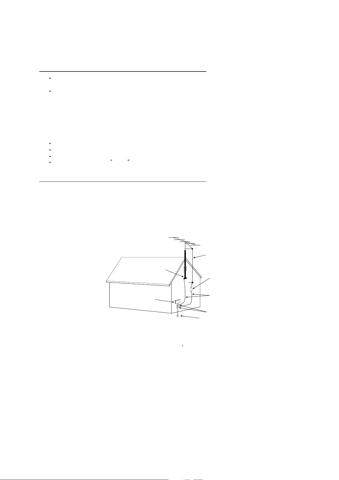
EXAMPLE OF ANTENNA GROUNDING AS PER NATIONAL ELECTRICAL CODE INSTR UCTIONS
EXAMPLE OF ANTENNA GROUNDING AS PER
NATIONAL ELECTRICAL CODE
ANTENNA
LEAD- IN WIRE
GROUND CLAMP
ELECTRIC SERVICE
EQUIPMENT
NEC-NATIONAL ELECTRICAL CODE
ANTENNA DISCHARGE
UNIT (NEC SECTION
810-20)
GROUNDING
CONDUCTORS
(NECSECTION 810-21)
GROUND CLAMPS
POWER SER VICE GROUNDING
ELECTRODE SYSTEM
(NEC ART 250. PART H)
15.2. Note to CATV system installer : (Only for the television set with CATV reception)
This reminder is provided to call the CATV system attention to Article 820-40 of the NEC that provides
installer s
guidelines for proper grounding and, in particular, specifies that the cable ground shall be connected to the grounding
system of the building, as close to the point of cable entry as practical.
16. An outside antenna system should not be located in the vicinity of overhead power lines or other electric lights or power
circuits, or where it can fall into such power lines or circuits. When installing an outside antenna system, extreme care
should be taken to keep from touching such power lines or circuits as contact with them might be fatal.
17. For added protection for this television set during a lightning storm, or when it is left unattended and unused for long
periods of time, unplug it from the wall outlet and disconnect the antenna. This will prevent damage due to lightning
and power-line surges.
4
4
Page 5

SCHNEIDER ELECTRONICS GMBH-GERMANY
OPERATION OF YOUR SET
18.
This television set should be operated only from the type of power source indicated on the marking label.If you are not
sure of the type of power supply at your home, consult your television dealer or local power company. For television
sets designed to operate from battery power, refer to the operating instructions.
19. If the television set does not operate normally by following the operating instructions, unplug this television set from the
wall outlet and refer servicing to qualifiedservice personnel. Adjust only those controls that are covered in the operating
instructions as improper adjustment of other controls may result in damage and will often require extensive work by a
qualified technician to restore the television set to normal operation.
20. When going on a holiday : If your television set is to remain unused for a period of time, for instance, when you go on
a holiday, turn the television set and unplug the television set from the wall outlet.
off
IF THE SET DOES NOT OPERATE PROPERLY
21. If you are unable to restore normal operation by following the detailedprocedurein your operating instructions,
do not attempt any further adjustment. Unplug the set and call your dealer or service technician.
22. Whenever the television set is damaged or fails, or a distinct change in performance indicates a need for
service, unplug the set and have it checked by a professional service technician.
23. It is normal for some TV sets to make occasional snapping or popping sounds, particularly when being
turned on or off. If the snapping or popping is continuous or frequent, unplug the set and consult your
dealer or service technician.
FOR SERVICE AND MODIFICATION
24. Do not use attachments not recommendedby the television set manufacturer as they may cause hazards.
25. When replacement parts are required, be sure the service technician has used replacement parts specified
by the manufacturer that have the same characteristics as the original part. Unauthorized substitutions
may result in fire, electric shock, or other hazards.
26. Upon completion of any service or repairs to the television set, ask the service technician to perform
routine safety checks to determine that the television is in safe operating condition.
5
5
Page 6
EM BUSINESS CENTER
r
TERMINALS
p()
Smart Volume
Yes
PACKAGE INFO
CC (Closed Caption)
Yes (CC1 CC4,Text1 Text4;
Gross Weight (Kg)
5.5
App
FTV PRODUCT MANAGEMENT DEPT.
SPECIFICATION RELEASE
Version: V2.1 Issued Date: 2013.03.27
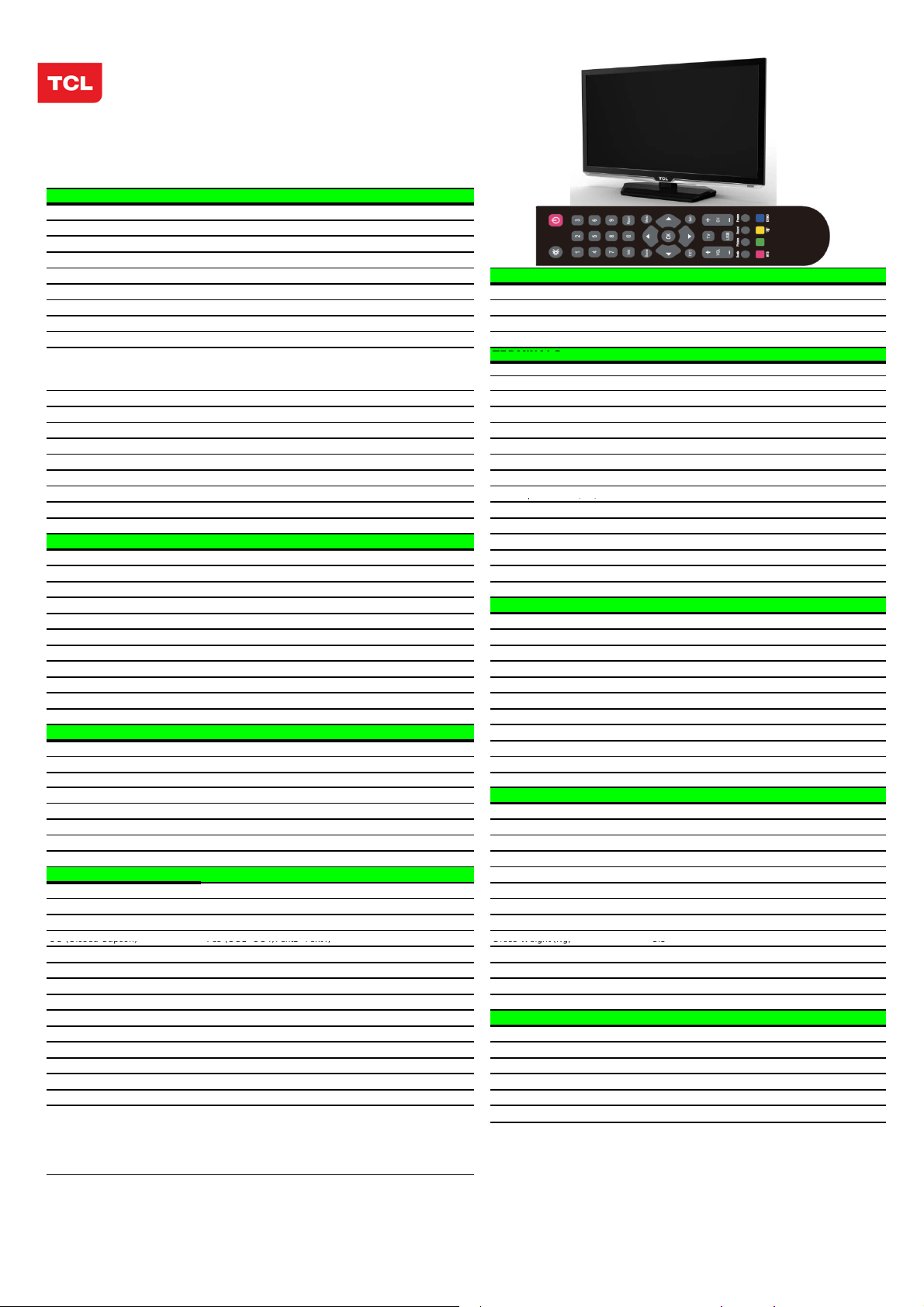
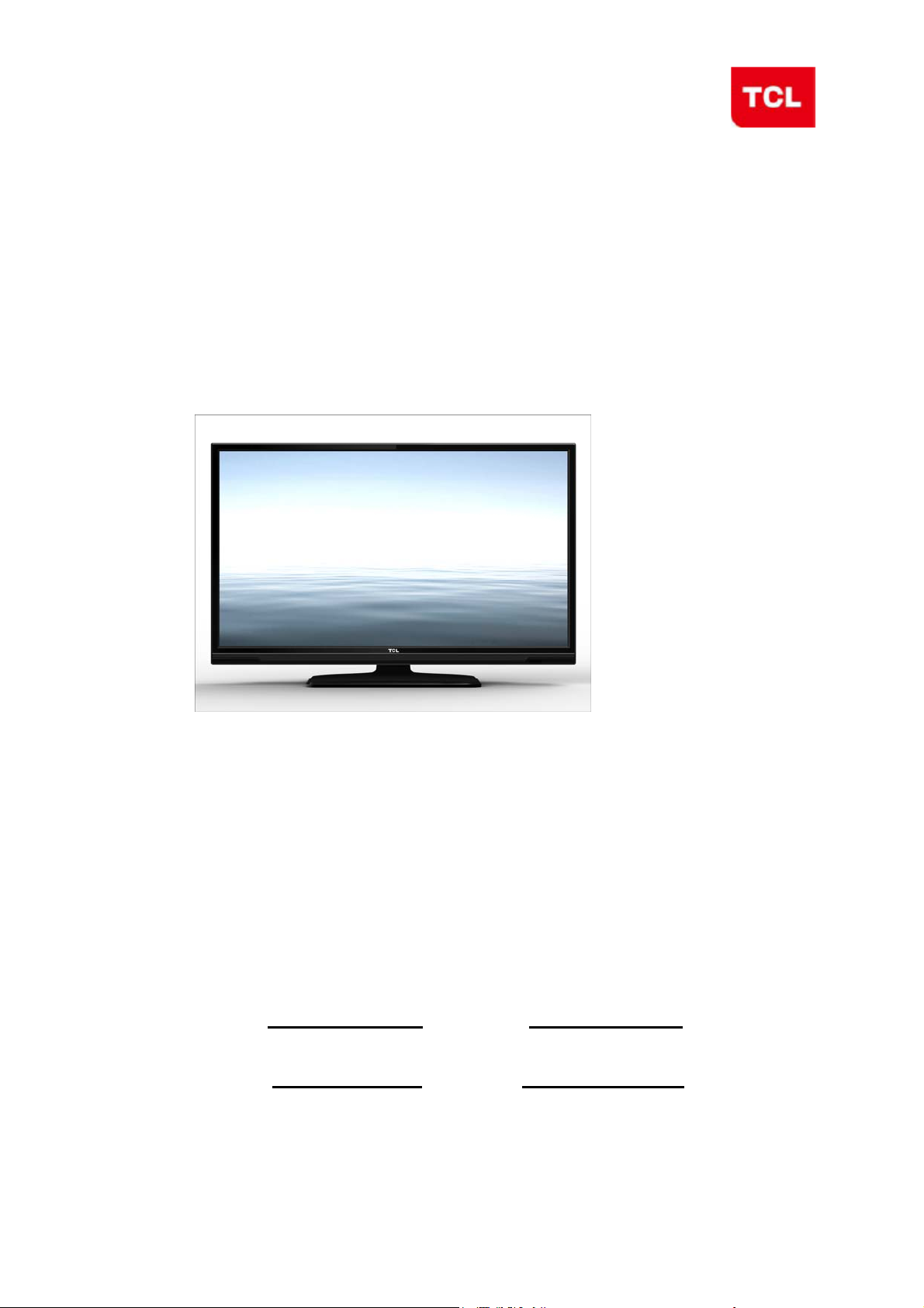
Model:L28E3500/MS82MT-LA
PICTURE
Category LCD TV
Naturalight Technology Yes (Natural Light Engine ‖)
Dynamic Contrast Yes
Color Temperature Warm / Normal / Cold
Backlight Adjustable Yes
Scale Mode Zoom,Expand,Original,Natural Component Video Format Y,PB/CB,PR/CR:up to 1080P
Picture Effect Standard, Bright, Soft, Personal DVI Video Format Up to XGA for HDMI-PC
Film Mode (3:2 pull down) AUTO HDMI Video Format up to 1080P
VGA Dot to Dot Display Yes (Natural) PC Compatibility Up to SXGA
Light Senso
--
Picture Enhancement and Audio share with YPBPR Audio
Comb Filter 3D YP
Adaptive Deinterlacing 3D Audio Input for YP
Blue Stretch Yes YC
Black Stretch Yes Audio Input for YC
Motion Compensation Yes VGA(PC) Input 1 (D-Sub,15 Pins)---in side
DLTI Yes Audio Input for VGA(PC) Share with Audio for "YP
DCTI Yes HDMI 1 (HDMI1) ---in side
Dynamic Skin Correction Yes CVBS Output (Composite) 1 RCA Video Socket ---in side
PANEL SPECIFICATION
Back light Unit LED Headphone Output - Panel supplier CSOT RF Input(Antenna) 1 (F Type)---in side
Aspect Ratio 16:9 USB 1(Standard)---in side
Panel Size (inch) 27.5"
Display Resolution 1366*768 TV System NTSC-M;PAL-M;PAL-N
Brightness (cd/m2) 240 AV System PAL,NTSC
Contrast Ratio 3000:1 Channels
Response Time Tr/Tf 6.5ms Chassis MS82MT-LA
Viewing Angle (H/V) 178°/178° Certification CB
Life Time 30,000hrs Power Supply AC 100V-240V 50/60Hz
Color 16.7M Power Consumption-TV on 35W
SOUND
Speakers Integrated speakers (Bottom side) Default Color of Front Cabinet Black
Audio Power Output 2×2.5W Keyboard Position Back
Woofer Power Output -- Base Stand Detachable
Sound Effect Stereo, Music, Movie, News,Personal Unpackaged Dimension for Main Body (L*H*D) (mm)
Sound Control Balance, Sound EQ Adjust; With Base Stand (mm) 657.7x450.4x175
Sound Features MTS(BTSC) Without Base Stand (mm) 657.7x409.9x69.7
Scene Selecting(DeskTop mode and HangUp mode)
FUNCTION
OSD Language English/Spanish/Portuguese Speaker Box
OSD Features Motion Bmp Style Base Stand
Source in OSD Source Bmp Icon Selecting Net Weight (Kg) 4.5
CC (Closed Caption) Yes (CC1~CC4,Text1~Text4; Gross Weight (Kg) 5.5
Clock/Sleep Timers Yes 20 feet 693
Wake up/Turn off time Yes 40 feet 1408
Wake up Source/Chanel Yes 40 feet high 1557
Watch Time Limit Yes
Startup Setting Yes(User can set a picture for turning on Logo display) Operation Manual English(Default)
Smart Switch Yes(Signal Auto Detecting and Changing Source) Remote Control For TV control (with two batteries)
Picture Freeze Yes Base Stand Integrated Packaging
DNR(Dynamic Noise Reduction) Off、Low、Middle、High Speaker Box Integrated
Hotel Menu In factory mode Wall Mount WMB233(Optional)
USB Connection
CC OFF,CC ON,CC On Mute,) Container Loading
Movie:Support H.264、RM/RMVB、XVID、FLV Others AV Adapter cable
DivX、MPEG2
Photo: Support JPEG、BMP、PNG;
Music: support MP3、WMA、M4A;
、MPEG4、VC1
Design and specifications are subject to change without notice!
SIGNAL FORMAT CAPABILITY
AV1 Input (Composite)
AV2 Input (Composite)
BPR Input 1---in side
BPR 1---in side
BCR Input Share with "YPBPR"
BCR Share with Audio for "YPBPR"
SPDIF Output
Audio/CVBS---R/L+ Video in side
1 (coaxial digital audio output)---in side
BASIC INFO.
Cable 125 (1~125) , Antenna 68 (2~69)
Power Consumption-Standby
≤1W
Yes
.
Packaged Dimension (L*H*D)
Main Body (mm) 718X490X128
ACCESSORIES
Drafted by:
Checked by:
Video Share with Y
BPR"
roved by:
Page 7
TCL Multimedia Technology Holdings Ltd.
R&D Center
Alignment Procedure
MS82MT-AP/LA Chassis
Version: 1.0
Release Date: 2013-03-26
PREPARED BY: Kangwei
APPROVED BY:
DATE: 2013-03-26
DATE:
Page 8
MS82MT-AP/LA Chassis Aliment procedure
Content
1. General Description 3
2. Factory Menu 3
2.1 Way of accessing 3
2.2 Factory Menu 4
2.3 ADC calibration menu 5
2.4 White Balance adjustment 6
3. Design Menu 7
3.1 way of accessing 7
3.2 SHOP Menu 8
3.3 Other Menu 9
3.4 Service Menu 10
3.5 PARAM SETTING MENU 11
3.6 Hotel Menu 12
4. Steps of debugging 13
4.1 Device 13
4.2 steps of debugging 13
4.3 ADC calibration 13
4.4 White Balance adjustment 14
4.5 White Balance adjustment (automatically) 16
5. Chip list of software programming before SMT 16
6. Appendix 17
6.1 Software upgrading through USB 17
6.2 Check software version, release date and Project ID 18
6.3 FAQ 20
History Description of major changes Release
Date
V1.0 2013-03-26
Chassis Model
FHD MS82MT-AP/LA L28E3500 etc
PRELIMINARY INFORMATION ----- SUBJECT TO CHANGE
2
Page 9
MS82MT-AP/LA Chassis Aliment procedure
1. General Description
MS82MT-AP/LA is our latest design especially for LCDTV products selling in Asia
Pacific (AP) and Latin America (LA) market. It features by its high integration,
easy debugging as well as convenience in terms of maintenance. Fast software
upgrade through USB disk facilitates both manufacture and after-sale service.
Meantime, a variety of functions involved in Factory Main Menu can not only
bring benefits for production, but also satisfy various demands of customer.
Note: Factory Main Menu (FMM) is divided into Factory Menu, Design Menu, Service
Menu and Hotel Menu. Factory Menu covers all indispensable functions during
manufacture such as White Balance Adjustment, ADC Calibration, USB Upgrading e.g.,
while the items under Design Menu is exclusively used by R&D engineer, anyone else
shouldn’t change the settings in the menu. When you wish to learn the product
information like project ID, model name, chassis name, software version, release date,
you can access to Service Menu. In addition, in Hotel Menu, we also provide a great
deal of useful functions for specific applications in hotel.
2. Factory Menu
2.1 Accessing way:
a. In the first place, press Menu button of
remote
control, then select Contrast item of Picture
submenu. Finally, press 9, 7, 3, 5 consecutively.
b. When the FAC HOTKEY item of Factory Menu
is enabled (ON), press Return button of remote
control.
PRELIMINARY INFORMATION ----- SUBJECT TO CHANGE
3
Page 10
MS82MT-AP/LA Chassis Aliment procedure
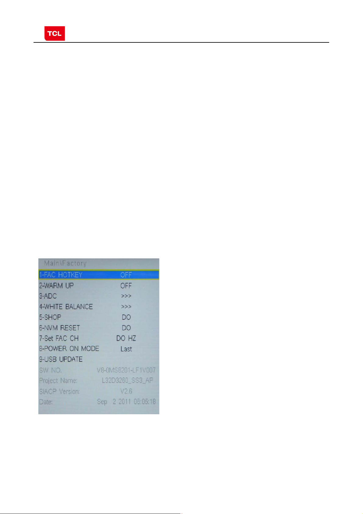
2.2 Factory Menu
Factory Menu
Name Default Description Status
FAC
HOTKEY
OFF Factory Menu shortcut button switch
The item must be disabled (OFF) after production
OK
WARM-
UP
ADC >> ADC calibration ( see details below) OK
WHITE
BALANCE
SHOP
NVM RESET DO Restore default value except WB and ADC data. OK
SET FAC CH DO Preset the channel table of factory. Option: HZ, WX, EGYPT-EL,
Power On
Mode
OFF OFF: Normal mode. Display blue screen when no signal. Turn to
automatically standby mode if keep the signal unavailable over
15 minutes.
ON: Aging mode. Display snow dot when no signal. The set will not
turn to standby even if the unavailability of signal;press
‘function’key to exit warm-up mode.
>> White Balance Adjustment ( see details below) OK
DO It is crucial that the function is executed after production aim to clear
information of production process, ensure user cannot access to
Factory Menu after executing the item.
ALGERIA e.g. To p reset th e ch annel table of certain factory, firstly,
choose the corresponding factory name, then press OK button of
remote control and wait until the disappearance of Factory Menu,
LAST/STB ON: the set will power on after switching on power.
STB: the set will remain standby status after switching on power.
Last: the set will turn to the status in which it lies when last switching
off.
If without requirement from certain customer,
by default, the Setting should be Last for MS82S-AP and STB for
MS82S-LA
OK
OK
OK
OK
USB
UPDATE
SW NO. OFF Version information of Main Software OK
Project
Name
SIACP
Version
Date Release date and time of main software OK
Upgrade software. Please see details below. OK
Product model OK
Serial port remote control protocol OK
PRELIMINARY INFORMATION ----- SUBJECT TO CHANGE
4
Page 11
MS82MT-AP/LA Chassis Aliment procedure
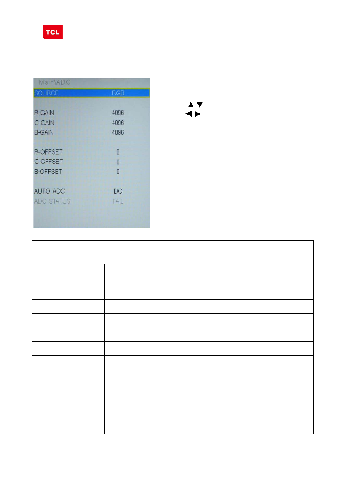
2.3 ADC calibration menu
ADC Menu
Press the button in remote control to select certain
item and
ADC calibration.
Notes:
1. Only YPBPR and RGB source should be calibrated.
to change the value of ADC data or start
ADC Calibration menu
Name Default Description Status
SOURCE Select the source you intend to ADC Calibrate.
R GAIN 4096 Gain of R channel ( cannot be changed after auto calibration) OK
G GAIN 4096 Gain of G channel ( cannot be changed after auto calibration) OK
B GAIN 4096 Gain of B channel ( cannot be changed after auto calibration) OK
R OFFSET 0 Offset of R channel ( cannot be changed after auto calibration) OK
Only YPBPR and RGB are available.
OK
B OFFSET 0 Offset of B channel ( cannot be changed after auto calibration) OK
G OFFSET 0 Offset of G channel ( cannot be changed after auto calibration) OK
AUTO ADC DO Select and execute the item, ADC Calibration starts. It indicates
ADC
STATUS
Show the ADC status of YPbPr/RGB Channel. SUCCESS will be
a successful calibration if prompt “OK” is displayed.
Otherwise, It is a failing calibration (“FAIL” is displayed).
display if YPbPr/RGB Channel has been correctly calibrated.
Otherwise FAIL will be displayed
OK
OK
PRELIMINARY INFORMATION ----- SUBJECT TO CHANGE
5
Page 12
MS82MT-AP/LA Chassis Aliment procedure
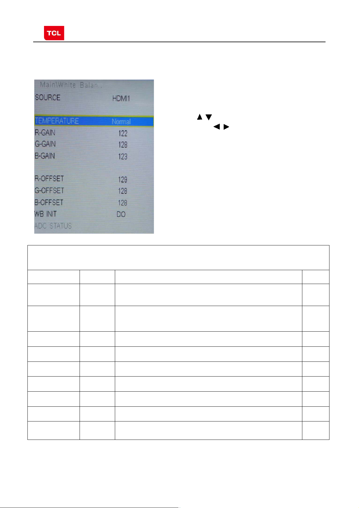
2.4 White Balance Adjustment menu
White Balance menu
Press the button in remote control to select
certain item and to adjust Wh ite Balance
White Balance Adjustment menu
Name Default Description Status
Source PC Select the source you intend to apply WB adjustment.
COLOR
TEMPERATURE
R GAIN
G GAIN
B GAIN
R OFFSET
Cool Select color temperature you intend to adjust Three groups of
-2
0
+9
+6
Only HDMI1, AV1, YPBPR, PC and should be adjusted.
color temperature: Normal, Warm, Cool are available for each
source.
Gain of R channel ( cannot be changed after auto calibration) OK
Gain of G channel ( cannot be changed after auto calibration) OK
Gain of B channel ( cannot be changed after auto calibration) OK
Offset of R channel ( cannot be changed after auto calibration) OK
OK
OK
G OFFSET
0
Offset of G channel ( cannot be changed after auto calibration) OK
B OFFSET
-2
Offset of B channel ( cannot be changed after auto calibration) OK
WB INIT
PRELIMINARY INFORMATION ----- SUBJECT TO CHANGE
White Balance Initalization. Before WB adjustment, this item should
be executed.
OK
6
Page 13

MS82MT-AP/LA Chassis Aliment procedure
3 Factory Main Menu
3.1 Accessing way:
1. In the first place, press Menu button of
remote control, then select Contrast item
of Picture submenu. Finally, press 1, 9, 5, 0
consecutively.
2. When the DESIGN HOTKEY item of Design
Menu is enabled (ON), press Return button of
remote control.
Press the button in remote control to select
certain item and
available options.
to toggle among or execute the
Main Menu
Name Default Description Status
DESIGN
HOTKEY
FACTORY
MENU
SHOP
INIT
OTHER
SERVICE
MENU
PARAM
SETTING
HOTEL
MENU
OFF Design Menu shortcut button switch
The item must be disabled (OFF) after production
>>> Access to Factory Menu OK
>>> Contain many options which can be chosen according to the
requirements of customers as default settings when leave factory.
See details below.
>>> The item includes a number of functions offering convenience for
R&D engineer to solve problems. It is exclusively used by R&D.
>>> Provide many useful information for aftersale service
Please reference to SERVICE MENU submenu
>>> Include volume, brightness, contrast, saturation, hue, sharpness,
backlight, volume, overscan Adjustment etc. Please reference to
PARAM SETTING submenu.
>>> Include special functions which bring benefits to hotel management.
The item is accessible only when HOTEL ENABLE item is enabled
(ON).
OK
OK
OK
OK
OK
OK
3.2 SHOP MENU
PRELIMINARY INFORMATION ----- SUBJECT TO CHANGE
7
Page 14

MS82MT-AP/LA Chassis Aliment procedure
Contain many options which can be chosen according
to the requirements of customers as default settings
when leave factory. Press the
control to select certain item and to toggle
among the available options..
button in remote
SHOP MENU
Name Default Description Status
VOLUME 30 Volume setting, 0~100 adjustable OK
PIC MODE STANDARD Picture mode. Options:
SOUND
MODE
STEREO Sound effects. Options:
BRIGHT, SOFT, PERSONAL,STANDARD
STAREO MISIC, MOVIE, NEWS
OK
OK
CH NUMBER 199 Maximum number of accessible channel NG
OSD
LANGUAGE
Preset CH 0 Preset channel. 0~199 optional OK
ENGLISH AP: English, French, Vietnamese, Russian, Arabic, Farsi, Hebrew,
Thai, Portuguese, Mongolian, LA: English, Portuguese, Spanish
OK
COLOR
TEMP
NORMAL Color temperature. Option: NORMAL, WARM, COOL OK
3.3 Other Menu
PRELIMINARY INFORMATION ----- SUBJECT TO CHANGE
8
Page 15

MS82MT-AP/LA Chassis Aliment procedure
Press the
certain item and to toggle among the available
options..
button in remote control to select
Other Menu
Name Default Description Status
VIF1 Exclusively used by R&D. OK
VIF2 Exclusively used by R&D. OK
VIF3 Exclusively used by R&D. OK
QMAP
ADJUST
SSC Spectrum Spread Control.
DBC
ENABLE
BP Parameter of DBC
CP Parameter of DBC
DBC MODE DBC Mode. Exclusively used by R&D. OK
MU0 DQS0 Manually adjust DQS1 phase of DDR2
MU1 DQS1 Manually adjust DQS1 phase of DDR1
Exclusively used by R&D. OK
OK
Exclusively used by R&D.
Dynamic Backlight Enable
Exclusively used by R&D.
Exclusively used by R&D.
Exclusively used by R&D.
Exclusively used by R&D
Exclusively used by R&D
OK
OK
OK
OK
OK
PRELIMINARY INFORMATION ----- SUBJECT TO CHANGE
9
Page 16
MS82MT-AP/LA Chassis Aliment procedure
TTX ON ON: enable teletext OFF: Disable teletext OK
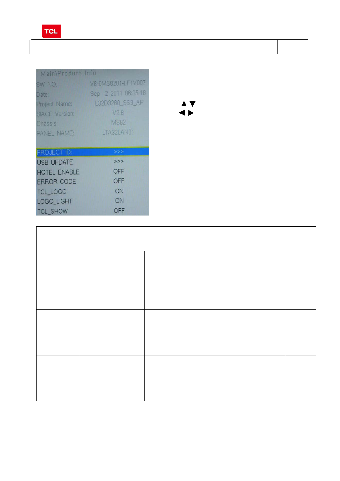
3.4 SERVICE MENU
Press the
item and to toggle among the available options..
button in remote control to select certain
SERVICE MENU (Product Info)
Name Default Description Status
SW NO. Software virtual code of Main Software OK
DATE Release date, time OK
Project Name Model of product OK
SIACP
Version
Chassis MS82S-AP/MS82S-LA Chassis name OK
Serial port remote control protocol
OK
P ANEL NAME Panel code OK
PROJECT ID Select project parameters through project ID. OK
USB UPDATE USB upgrad e. OK
HOTEL
ENABLE
Switch of Hotel Menu. OK
PRELIMINARY INFORMATION ----- SUBJECT TO CHANGE
10
Page 17

MS82MT-AP/LA Chassis Aliment procedure
ERROR
CODE
TCL_LOGO Display TCL Logo or not. On : display ,
LOGO_LIGHT OK
TCL_SHOW DEMO function ON/OFF OK
NG
OK
Off: not display
3.5 PARAM SETTING MENU
Press the
and
button in remote control to select certain item
to enter menu.
PARAM SETTING MENU (Setting menu)
Name Default Description Status
Brightness
Curve
Contrast
Curve
Saturation
Curve
>>> Brightness curve. Exclusively used by R&D. OK
>>> Contrast curve. Exclusively used by R&D. OK
>>> Saturation curves. Exclusively used by R&D. OK
Hue Curve >>> Hue Curve Exclusively used by R&D. OK
Volume
Curve
>>> Volume curve. Exclusively used by R&D. OK
Backlight
Curve
OverScan >>> Overscan adjustment. Exclusively used by R&D. OK
PRELIMINARY INFORMATION ----- SUBJECT TO CHANGE
>>> Backlight curve. Exclusively used by R&D. OK
11
Page 18

MS82MT-AP/LA Chassis Aliment procedure
3.6 HOTEL MENU
Press the
certain item and
button in remote control to select
to enter submenu.
Name Default Description Status
POWER
LOGO
CH LOCK OFF Channel scan lock. OK
ON LOGO select OK
HOTEL MENU
MAX VOL 100 Max volume OK
AUTO SET OFF The switch of PIC, SOUND etc.
PIC MODE Standard Picture mode. OK
SOUND
MODE
POWER
VOL.
POWER
SIGNAL
POWER
CHANNEL
KEY LOCK OFF Lock the keys. OK
SA VE DATA
TO
WRITE
DATA TO
PRELIMINARY INFORMATION ----- SUBJECT TO CHANGE
STEREO Sound mode OK
50 Default volume when power on OK
ATV Default signal source when power on OK
0 Default channel no. when power on OK
DO Save the settings of Hotel Menu to USB OK
DO Copy the settings of Hotel Menu from USB OK
When it is ON, these items are selectable.
OK
12
Page 19

MS82MT-AP/LA Chassis Aliment procedure
g
p
g
ging
4. The steps of debuggin
4.1 Device
Color Analyzer CA-210. Video Pattern Generator Chroma2329. Color TV Pattern
Generator PM5418, VGA cable, AV cable(RCA),YPBPR(RCA) cable.
。
Chroma2329
4.2 ste
s of debu
Fluke5418 CA-210
:
According to the requirement of order, we suggest take the below steps to finish
the appropriate settings.
A enter the Factory Menu, enable FAC HOTKEY
B Check the version of software, release date displayed at the bottom of Factory
Menu. If the information is correct, you can ignore step C and D.
C Enter Factory Main Menu, choose SERVICE MENU->PROJECT ID, choose
corresponding Project ID number of the product (Please refer to the description in
BOM about Project ID number).
D return to Factory Menu, check the Product model.
E choose Factory Menu-> NVM RESET and press and wait until prompt OK
appears.
F restart the set
G according to the requirement of order, set the items of Shop Menu and Hotel
Menu etc.
H After aging under normal temperature, calibrate ADC and adjust white balance.
I choose Factory Menu-> SHOP INIT and press button of remote control to
initialize the set.
Note: after step I (execute SHOP INIT), Hotel Menu will be disabled by default.
Therefore, if order requires hotel function, it is necessary to enable hotel function by
Factory Main Menu-> Service Menu->HOTEL ENABLE to ON.
set
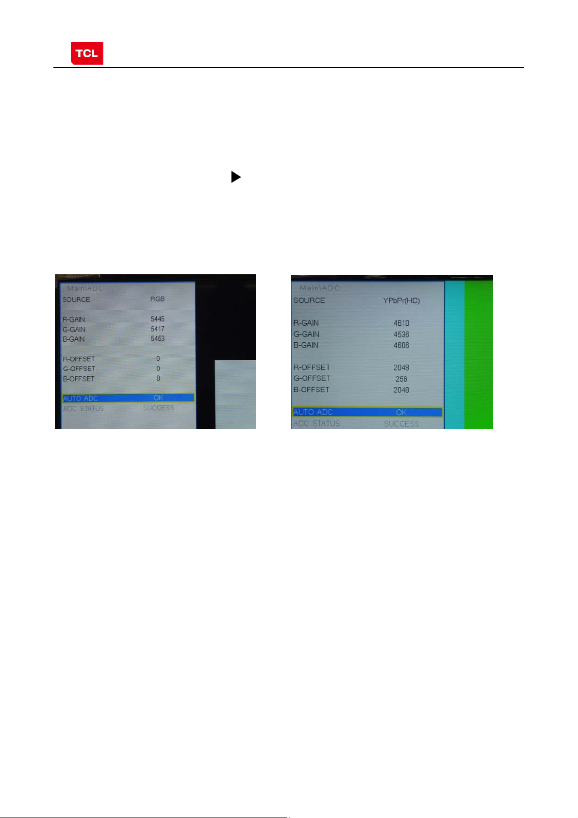
4.3 ADC Calibration
Ⅰ.signal and generator
VGA: Chroma2329 Pattern42, Timing 14(1024x768@60Hz 5 MOSAIC)
YPBPR: Chroma2329 Pattern103, Timing 79(100% Color Bar, 720p)
5 MOSAIC 100% Color Bar
PRELIMINARY INFORMATION ----- SUBJECT TO CHANGE
13
Page 20
MS82MT-AP/LA Chassis Aliment procedure
Ⅱ.steps of debug:
1) Access to the Factory menu->ADC
2) Select PC source
3) Select AUTO ADC,Press button in your remote control to calibrate the
ADC automatically.
4) Select YPBPR source
5) Repeat step 3.
6) When the OK appears the calibration has been finished successfully.
VGA calibration YPBPR calibration
4.4 White Balance adjustment (Manual)
Before adjustment, you must ensure Color Analyzer has been calibrated. Only AV1,
YPBPR, VGA , HDMI 1 need to be adjusted. It is necessary to adjustment HDMI 1
firstly.
a. signal and generator
The pattern of the signal should be used are White (Chroma2329 pattern113) and
Grey (pattern 114).The format of signal are respectively 720p for HDMI1
(Chroma2329 Timing 69), NTSC for AV1 (Chroma2329 Timing 37),1024×768@60Hz
(Chroma2329 Timing 14) for VGA and 720p (Chroma2329 Timing 79)for YPBPR
b. steps of adjustment
1) enter the factory menu->WHITE BALANCE, select source HDMI 1 and COLORTEMP
normal.
2) input grey signal in 720p format
3) change R OFFSET and B OFFSET to make sure the value of color coordination
equal to the value required by enterprise standard (x, y).
PRELIMINARY INFORMATION ----- SUBJECT TO CHANGE
14
Page 21

MS82MT-AP/LA Chassis Aliment procedure
4) input white signal in 720p format
5) change R Gain and B Gain to make sure the value of color coordination equal to
(x, y).
6) repeat step 2~5 until both of the value of color coordination of white and grey
equal to (x, y).
In addition to select COLORTEMP COOL/WARM, the adjustment method of COOL
and WARM color temperature is same with that of NORMAL. The color coordination
we recommend is as follows:
Device:CA-210; Accuracy:±0.015
Model WARM NORMAL COOL
L28E3500
L24E3500
L24E3510F
L28E4100
X 0.294 0.277 0.256
Y 0.305 0.293 0.268
X 0.280 0.265 0.250
Y 0.300 0.285 0.265
X 0.290 0.270 0.248
Y 0.310 0.292 0.278
X 0.282 0.267 0.250
Y 0.291 0.280 0.257
HDMI White Balance adjustment
PRELIMINARY INFORMATION ----- SUBJECT TO CHANGE
15
Page 22

MS82MT-AP/LA Chassis Aliment procedure
4.5 ADC Calibration and White Balance Adjustment (automatic)
The process of adjusting ADC and White Balance automatically is out of the range
of this file. Please refer to the relevant technical file of HuiZhou factory of TCL
5. Chip list of software programming before SMT
Following chips must be programmed before SMT by ALL-11 or other tools.
Position Chip type Chip name Part number Software
description
1 U502 Flash EN25Q32B 13-EN25Q3-2BBEO main software SO-8
2 U702 E2PROM M24C32MN 13-M24C32-MNB Tcon software SO-8
Note:
1) The software for U502 and U702 can be program using ISP tool.
2) Every set has its unique HDCP key which is purchased from suppliers or HDCP
certification authority. Please check HDCP function in the process of production.
3) Once in a while, the software of main board may be upgraded. Please pay attention to
use the latest software before production.
Decal
PRELIMINARY INFORMATION ----- SUBJECT TO CHANGE
16
Page 23

MS82MT-AP/LA Chassis Aliment procedure
Appendix:
1. Software upgrade through USB disk
1) Please ensure the software you are using has a correct file name
TCL_MS82_UPDATE.bin, then copy it to the root directory of a USB disk.
2) Insert the USB disk to the USB socket of the set for which you are
going to upgrade program.
3) Enter the Factory Menu (you can choose either a or b way below)
a. In the first place, press Menu button of remote
control, then select Contrast item of Picture
submenu. Finally, press 9, 7, 3, 5 consecutively.
b. When the Factory hotkey ite m of Factory Menu
is enabled (ON), press Return button of remote
control.
4) select USB UPDATE, press buttonof remote control, a pop menu
will appear prompting whether start upgradeor not. Press Yes to start upgrade,
press No to canel. Please wait patiently until the set restart automatically after
upgrade. Do not cut off the power supply during the process.
Upgrade Main Software
PRELIMINARY INFORMATION ----- SUBJECT TO CHANGE
17
Page 24

MS82MT-AP/LA Chassis Aliment procedure
2. Check software version, release date and Project ID
After upgrading, sometimes you may not certain whether the new software has
been successfully updated or not. In this case, you can check the software version
and release date in Factory Main Menu to make sure the success of upgrading.
In addition, for the convenience of software management, many models of same
chassis may share a same software, but are allocated with different Project ID.
In another words, every model has its unique Project ID. Obviously, Both software
version and Project ID are highly critical to ensure the set work properly. Therefore,
after upgrading software,we suggest you check these information by following
method.
1) Enter the Factory Main Menu(you can choose either a or b way below
a In the first place, press Menu button of remote control, then select Contrast item
of Picture submenu. Finally, press 1, 9 5, 0 consecutively.
b. When the DESIGN HOTKEY item of Factory Main Menu is enabled (ON), press
Return button of remote control.
2) Check the version of software, release date displayed at the bottom of Factory
Main Menu. If the information is correct, you can ignore step C and D.
3) choose SERVICE MENU->PROJECT ID, choose corresponding Project ID number of
the product (Please refer to the description in BOM about Project ID number).
4) choose Factory Menu and press OK button of the remote. Next, select NVM RESET
and press and wait until prompt OK appears.
5) choose SHOP INIT and press
button of remote control to initialize the set.
Note: after step I (execute SHOP INIT), Hotel Menu will be disabled by default.
Therefore, if order requires hotel function, it is necessary to enable hotel function by
set
Factory Main Menu-> Service Menu->HOTEL ENABLE to ON.
6) restart the set.
PRELIMINARY INFORMATION ----- SUBJECT TO CHANGE
18
Page 25

MS82MT-AP/LA Chassis Aliment procedure
Product
Information
Check product information
Remote Control name
Power Supply name
Audio Channel number
Change project ID
PRELIMINARY INFORMATION ----- SUBJECT TO CHANGE
19
Page 26

MS82MT-AP/LA Chassis Aliment procedure
3. FAQ
1) Why there is no picture after upgrading software or changing project ID?
It may be caused by fault of project ID. You can try below method to fix
the problem.
a. If the resolution of the panel of your set is 1366×768(HD panel), you can press
Menu, and 4976 of remote control in series after turning on.
b. If the resolution of the panel of your set is 1920×1080(FHD panel), you
can press Menu, and 4973 in series after turning on.
c. If you can see the picture at this time, please recheck the project ID again. If
the project ID is still wrong, correct it reference to above description.
PRELIMINARY INFORMATION ----- SUBJECT TO CHANGE
20
Page 27

8 7 6 5
4 3 2 1
R106
82K
R115
R107
R108
6K8
R109
510R
R116
30K
R117
51K
R118
2K2
C111
NC/
39K
NC/
GND
C122
GND
0.022U
0.022U
C113
22U
C123
22U
C114
10U
C124
22U
MAX_2A
GND
C125
10U
GND
C115
10U
MAX_2A
D101
NC/
D103
NC/
5V6
5V
F
5V6
E
VDDC
D
L101
8.2UH
U104
FB
VCC
BST
MP1494
10R
R105
12V---5V/1.5A
Fixed Fsw=500kHZ
L102
4.7UH
U105
FB
VCC
BST
MP1494
10R
R114
12V---1.2V/2A
Fixed Fsw=500kHZ
8
7
6
5
8
7
5
GND
GND
C108
0.1U
82K
C126
0.1U
VIN
3
GND
C106
0.1U
GND
U101
AS1117-1.8
VIN
3
GND
4
4
OUT
2
VIN
4
OUT
3
4
2
GND/ADJ
1
C129
0.1U
U102
AS1117-2.5
4
4
GND/ADJ
OUT
1
2
GND/ADJ
1
C127
0.1U
C128
0.1U
3V3_NORMAL
T
C102
100U
16V
2V5
T
1V8_DDR
T
C136
100U
16V
3V3_NORMAL
2V5
C137
100U
16V
1V8
12V
12V
C101
10U
C116
10U
GND
GND
C103
0.1U
C119
0.1U
R103
75K
R104
R110
75K
R113
20K
20K
GND
GND
1
AAM
2
IN
3
SW EN/SYNC
4
GND
GND
C107
0.1U
C104
0.1U
1
AAM
2
IN
3 6
SW EN/SYNC
4
GND
GND
C121
0.1U
C120
0.1U
AS1117-3.3
F
DIM
BL_ON
P_ON
E
3V3_STB
GND
1 2
3
5
7
9
11
13
P102
4
6
8
10
12
14
DIM
BL_ON
P_ON
3V3_STB
GND3
T T
12V_A
P_ON
T
GND4
12V_A212V_A1
T T
3V3_STB
T
GND
5V
D
3V3_STB
R127
3K3
(5)
POWER_ON
R123
330R
P_ON
U103
C130
0.1U
C118
0.1U
BL_ON
T
DIM_PWM
T
C
GND
R126
330R
1
2
3
4
5
GND
KEY
BL_ON
GND
KEY
C117
0.1U
T
LED
GND
T
C133
0.1U
3V3_STB
IR
GND
T
3V3STB
T
R121
220R
R122
1K
C132
1000P
D102
2
R120
47K
F2
BL_ON_OUT
R125
10K
B
P101
A
1000P
0BAV99NC/
3
C135
DIM
C131
0.01U
1
close to P100
GND
GND
R119
22K
C134
0.1U
R124
220R
3V3_STB
IR_IN
LED_OUT
KEY_IN
THIS DRAWING CANNOT BE COMMUNICATED TO UNAUTHORIZED PERSONS COPIED UNLES S PERMITTED IN WRITING
DIM_OUT
(5)
R102
4K7
NC/
GND
Q101
12V
R129
10K
G
GND
T
D
C139
4U7
1U
GND
R130
15K
C145
GND2
T
12V
P_ON
C
B
MDD3752
12V_A
R131
100K
Q102
BT3904
U106
C110
NC/
USB_5V
10U
1
FLG
2
GND
RT9711
NC/
VOUT
VINEN/EN#
5
R101
0R
43
5V
GND
C105
1U
NC/
GND
D104
MBRX14
D105
NC/
C
E
C140
1000P
NC/
R128
680R
S
6V8
B
SBU :
TCLNO:
Index-Lab
DATE
DESCRIPTION Last modifNAME
Last saved :
5
4678
.............
TCL Thomson Electronics Singapore Pte. Ltd.
8 Jurong Hall Road #28-01/06
The JTC Summit SINGAPORE 609434
DESIGNATION
DRAWN
DESIGNATION
3 2 1
ON:
BY:
Tel (65) 63092900 Fax (65) 63092999
CHECKED
PAGE:
ON:
BY:
OF :
A
FORMAT DIN A2
Page 28

8 7 6 5
TDA18273+CAN_TUNER_ONBOARD_COMP SCH, VER1.0 2012-7-25
4 3 2 1
F
TU_3V3
RT2
0R
TUNER_VCC
CT18
CT19
CT20
CT21
CT22
CT23
Caution:
CT24
TU_3V3 must be from LDO
GND
LT3
LT4
LT5
8.2NH
LT6
P
100NH
F
CT5
1
2
3
4
5
6
7
8
9
10
0.22U
VCC1-RF
RFIN
NC1
NC2
GND1
AS_XTSEL
GND2
TEST1
TEST2
GND3
TUNER_VCC
2.4NH
2.2NH
38
34
35
36
37
39
40
CAPRFAGC
RFAGC_SENSE
UHFSUPPLY
UHFLOW
VCC2-RF
VHFHIGH
UHFHIGH
TDA18273HN
UT1
TDA18273HN
CAPREGVCO
VCC-SYNTH
XTALN
XTALP
GND4
SDA
SCL
111213141516171819
CT6 0.1U
31
32
33
VHFSENSE
VHFLOW
VHFSUPPLY
VSYNC
VIFAGC
VCC-IF
XTOUT2
XTOUT1
VTUNE
GND5
CP
20
IRQ
GND7
IFP
IFN
GND6
GND
CT7
6800P
30
29
28
27
26
25
24
23
22
21
TUNER_VCC
0.1U
0.1U
T
Z12
CT10
CT11
CT8
10P
CT9
10P
RT8
0R
0R
RT9
RT7
1K
VIF+
VIF-
E
GND
10U
0.047U
0.047U
0.047U
0.047U
100P
0.047U
GND
3
0BAV99
DT1
TUNER_VCC
CT4
82P
2
GND
RT1
0R
GND
E
CT1 CT2
120P
LT1
0.33UH
GND
120P
LT2
CT3
150P
1
0.22UH
GND
TUN1
GND1
GND2
GND3
GND4
GND5
GND6
1
S1
2
3
4
5
6
7
FT1
GND
RT6
6800P
0.1U
TUNER_VCC
CT12
CT14
CT15
2700P
D
CT33
22P
CT34
22P
GND
430R
CT13
0.22U
D
GND
RT15
33R
33R
RT16
GND
CT16
30P
XT16M
CT17
30P
16M
TU_3V3
4
C202
0.1U
VIN
4
GND/ADJ
OUT
1
2
3
TU_3V3
T
300mA
C
TU_3V3
GND
C203
220U
16V
C204
GNDGND
B
C
ANT
3V3
SCL
SDA
GND
XOUT
IF_N
IF_P
IF_AGC
TUN2
NC/
IF_AGC
B
1
TU_3V3
2
3
4
5
6
7
8
9
T
TU3V3
T
T
GND1
GND
CT37
NC/
CT32
NC/
CT30
NC/
IF- IF+
22P
GND GND
RT14
NC/
1K
6800P
10U
T_SCL
GND
NC/
CT29
TT
CT38
NC/
22P
T
22P
T_SDA
T
NC/
GND
RT12
NC/
RT13
NC/
CT28
22P
33R
33R
RT10
4K7
4K7
RT11
TUNER_SCL
TUNER_SDA
IF_AGC
0.047U
C205
R201
10K
RF_AGC
TU_3V3
R202
10K
5V
RF_AGC
U201
AS1117-3.3
C201
10U 0.1U
GND
A
THIS DRAWING CANNOT BE COMMUNICATED TO UNAUTHORIZED PERSONS COPIED UNLES S PERMITTED IN WRITING
GND
SBU :
TCLNO:
Index-Lab
DATE
DESCRIPTION Last modifNAME
Last saved :
5
4678
.............
TCL Thomson Electronics Singapore Pte. Ltd.
8 Jurong Hall Road #28-01/06
The JTC Summit SINGAPORE 609434
DESIGNATION
DRAWN
DESIGNATION
3 2 1
ON:
BY:
Tel (65) 63092900 Fax (65) 63092999
CHECKED
PAGE:
ON:
BY:
OF :
A
FORMAT DIN A2
Page 29

8 7 6 5 4 3 2 1
AV IN 1
CLOSE TO SOC
C318
C301
560P
0.047U
C317
2U2
C316
2U2
AV1_V_IN
AV1_L_IN
AV1_R_IN
R307
12K
560P
C319
R316
100R
12K
R308
F
E
GND8
AV1_V
AV1_L
AV1_R
T
F4
R301
10K
R302
10K
R306
75R
GND
YPBPR_AV2_IN
(5)
(5)
(5)
HD_R
HD_L
GND
R303
10K
R304
10K
GND
R318
12K
C302
560P
R322
C303
560P
12K
CLOSE TO SOC
C314
2U2
C310
2U2
HD1_R_IN
HD1_L_IN
(5)
(5)
5V
R319
10R
AVOUT1_V
C320
10U
GND
R315
75R
C315
0.1U
BT3906
Q302
E
C
BT3904
220R
B
R314
R320
150R
Q301
C
E
R313
470R
C311
NC/
F
R321
8K2
B
R317
NC/
22P
15K
1K
R312
AVOUT1_V_OUT
E
AV OUT
CLOSE TO SOC
GND
AV1_L
D
P301
WHITE
WHITE
RED
RED
6
5
4
3
2
1
HD_L
HD_R
T
T
AV1_L
HD_L
AV1_R
T
T
F10
F9
F11
AV1_R
HD_R
F12
SPDIF
R325
120R
C313
33P
GND
C
GND
USB
GND7
T T
USB2_DP
USB2_DM
T
USB_5V1
T
USB_5V
B
VCC
GND
P302
1
2
D-
3
D+
4
F14
F13
C307
0.1U
GND
C306
220U
16V
R327
2R2
2R2
R326
USB2_D-_IN
USB2_D-_IN
USB2_D+_IN
USB2_D+_IN
(5)
(5)
A
THIS DRAWING CANNOT BE COMMUNICATED TO UNAUTHORIZED PERSONS COPIED UNLES S PERMITTED IN WRITING
R323
220R
C312
0.1U
...
...
...
...
SPDIF_OUT
T
HD_Y/AV2_IN
GND
DD-MM
DD-MM
DD-MM
DD-MM
DATE DESCRIPTION Last modifNAMEIndex-Lab
Last saved :
GND9
F7
F3
HD_PR
75R
HD_PB
75R
R328
75R
R329
...
...
...
...
(5)
R324
F8
...
...
...
...
1-26-2013_12:46
CLOSE TO SOC
R305
47R
R309
47R
R310
47R
10R
R311
45678
0.047U
C304
1000P
C309
0.047U
C308
C305
0.047U
D
AVOUT1_V
T
HD_Y/AV2_IN
HD_PB
T
GND
T
AVOUT1_V
SPDIF
T
SPDIF
HD_PB
AV1_VHD_PR
T
T
HD_PR
GND5
T
C
AV1_V
HD1_PR_IN
HD1_PB_IN
HD1_Y_IN+
HD1_SOG_IN
(5)
(5)
(5)
(5)
YELLOW
GREEN
BLACK
BLUE
YELLOW
RED
HD_Y/AV2_IN
P303
9
8
7
6
5
4
3
2
1
B
...
...
...
...
SBU :
TCLNO:
.............
DESIGNATION
...........
ADDRESS1
ADDRESS2
ADDRESS3
TELEPHONE
DRAWN
ON:
BY:
TCL
CHECKED
DD-MM-YY
ON:
BY:
......
PAGE:
OF :
A
10
3
123
FORMAT DIN A3
Page 30

8 7 6 5 4 3 2 1
P401
GND10
P402
17
RX2+
GND1
F
RX2-
RX1+
GND2
RX1-
RX0+
GND3
RX0-
RXC+
E
GND4
RXC-
NC1
NC2
DDCCLK
DDCDA
GND5
VCC
HPD
D
1
2
3
4
5
6
7
8
9
10
11
12
GND
CEC
H1_ARC
H1_SCL
H1_SDA
H1_5V
H1_HPD
C404
R423
R422
10K
R417
R406
1U
100R
100R
1K
13
14
15
16
17
18
19
10K
NC/
R414
H1_RX2+_IN
H1_RX2-_IN
H1_RX1+_IN
H1_RX1-_IN
H1_RX0+_IN
H1_RX0-_IN
H1_RXC+_IN
H1_RXC-_IN
R418
100R
0R
R421
R407
10K
R413
10K
C405
H1_ARC_OUT
0.1U
H_CEC
H1_SCL_IN
H1_SDA_OUT
H1_DET
R412
22K
6
11
1
7
12
2
8
13
3
9
14
4
10
15
5
16
T
GND
VGA_TX
T
T
VGA_SDA
T
VGA_SDA
VGA_GRN
VGA_HS
VGA_BLU
75R
R411
VGA_R
VGA_TXD
75R
R401
3V3_STB
VGA_G
T
T
VGA_HS
VGA_VS
VGA_VS
75R
R402
VGA_RED
VGA_B
T
T
VGA_RXD
2K2
R403
GND
2K2
R404
close to soc
R426
33R
R425
33R
R410
33R
R424
T
VGA_RX
T
VGA_SCL
VGA_SCL
10R
R409
100R
C406
C401
0.047U
C403
R405
100R
0.047U
C402
4700P
0.047U
VGA_RED_IN
VGA_GRN_IN
VGA_SOG_IN
VGA_HS_IN
VGA_BLU_IN
VGA_VS_IN
VGA_TXD
VGA_RED
GND
F16
VGA_SDA
VGA_GRN
F17
F19
F18
VGA_HS
VGA_BLU
F21
F20
VGA_VS
VGA_RXD
F23
F22
F
VGA_SCL
E
F24
D
GND
C
BT3904
Q401
R408
B
E
4K7
H1_HPD_OUT
C
GND
CEC
H1_5V
H1_SCL
H1_SDA
H1_HPD
F25
GND
H1_ARC
F27
F26
F28
F29
F30
B
A
THIS DRAWING CANNOT BE COMMUNICATED TO UNAUTHORIZED PERSONS COPIED UNLES S PERMITTED IN WRITING
...
...
...
...
DD-MM
DD-MM
DD-MM
DD-MM
DATE DESCRIPTION Last modifNAMEIndex-Lab
Last saved :
VGA_SDA
VGA_SCL
...
...
...
...
VGA_TXD
VGA_RXD
...
...
...
...
4-14-2009_15:30
45678
R415
R419
R420
100R
100RR416
100R
100R
R112
R111
4K7
4K7
C
UART_TX
UART_RX
B
...
...
...
...
SBU :
TCLNO:
.............
DESIGNATION
...........
ADDRESS1
ADDRESS2
ADDRESS3
TELEPHONE
DRAWN
ON:
BY:
TCL
CHECKED
DD-MM-YY
ON:
BY:
......
A
PAGE:
OF :
123
FORMAT DIN A3
Page 31

8 7 6 5
4 3 2 1
3V3_NORMAL
VDDC
600mA
2U2
C506
F
C539
GND
0.1U
0.1U
C538
0.1U
C537
0.1U
C536
0.1U
C535
0.1U
C527
2U2
C505
GND
C546
1V8
200MA
C501
10U
0.1U
C534
0.1U
C533
0.1U
C532
C531
0.1U
0.1U
C530
GND
E
GND
J9
H10
H9
R7
P7
P6
R5
R4
P4
G3
G2
G1
GND2
H_CEC
H1_HPD_OUT
H1_RXC-_IN
H1_RXC+_IN
H1_RX0-_IN
H1_RX0+_IN
H1_RX1-_IN
D
C524
R519
68R
R520
68R
R522
68R
C
GND
0.047U
C525
0.047U
C526
0.047U
H1_RX1+_IN
H1_SDA_OUT
H1_RX2-_IN
H1_RX2+_IN
H1_SCL_IN
H1_ARC_OUT
VGA_HS_IN
VGA_BLU_IN
VGA_SOG_IN
VGA_GRN_IN
GIN0M
VGA_RED_IN
VGA_VS_IN
HD1_PB_IN
HD1_SOG_IN
HD1_Y_IN+
HD1_Y_IN-
HD1_PR_IN
AV1_V_IN
VCOM0
AVOUT1_V_OUT
HD1_L_IN
HD1_R_IN
AV1_L_IN
AV1_R_IN
AUVAG
AUVRM
AMP_L_OUT
AMP_R_OUT
M1
M2
M4
M3
D6
D5
C7
B7
C6
B6
A6
C5
C4
A5
B5
B4
D4
A3
A2
B3
B2
B1
C3
D3
C1
C2
D1
D2
E4
E3
E2
F3
F2
F1
F4
H3
H2
J3
J2
J1
K3
K1
K2
L1
L2
N1
N2
P1
L3
P2
R1
N3
N4
P3
R2
T2
CEC
HOTPLUGD
RXCKN_D
RXCKP_D
RX0N_D
RX0P_D
RX1N_D
RX1P_D
DDCDD_DA
RX2N_D
RX2P_D
DDCDDD_CK
HOTPLUGA
RXCKN_A
RXCKP_A
RX0N_A
RX0P_A
RX1N_A
RX1P_A
DDCDA_DA
RX2N_A
RX2P_A
DDCDA_CK
ARC
HSYNC0
BINOP
SOGIN0
GIN0P
GIN0M
RIN0P
VSYNC0
BIN1P
SOGIN1
GIN1P
GIN1M
RIN1P
VSYNC1
CVBS2
CVBS1
CVBS0
VCOM
CVBSOUT
AUL0
AUR0
AUL1
AUR1
AUVAG
AUREFM
AUL2
AUR2
AUL3
AUR3
AUOUTL1
AUOUTR1
AUOUTL0
AUOUTR0
GND1
XIN
T3
M_XTALO
GND5
GND4
GND3
PGA-COM
VIFM
XOUT
P5
R6
R3
VIF-
VIF+
M_XTALI
AVSS_PGA
T5
GND6
GND7
VIFP
RFAGC
T6
T4
RF_AGC
P10
T7
GND9
GND8
B_ODD0/LVA4P
R10
GND13
GND12
GND10
GND11
B_ODD1/LVA4M
B_ODD2/LVA3P
B_ODD3/LVA3M
B_ODD4/LVACLP
B_ODD5/LVACKM
T11
P11
P12
R11
TXE3-
TXEC-
TXE3+
TXEC+
H11
J10
J11K9K10
GND15
GND14
GND16
GND17
B_ODD6/LVA2P
B_ODD7/LVA2M
G_ODD0/LVA1P
G_ODD1/LVA1M
T12
P13
P14
R12
R13
TXE1-
TXE2-
TXE0+
TXE1+
TXE2+
B
AUVRM
AUVRP
AUVAG
C504 0.1U
C510
10U
C511
10U
C512 0.1U
22P
L502
120R
CLOSE TO IC
A
GND
C520
24M
X24M
22P
C521
GND
THIS DRAWING CANNOT BE COMMUNICATED TO UNAUTHORIZED PERSONS COPIED UNLES S PERMITTED IN WRITING
0.1U
0.1U
C545
K11
A12
F13
G13
GND18
GND19
GND20
GND21
GND22
GND23
G_ODD2/LVA0P
G_ODD3/LVA0M
G_ODD4/LVB4P
G_ODD5/LVB4M
G_ODD6/LVB3P
G_ODD7/LVB3M
T14
T15
R14
R15
R16
TXE0-
TXO3-
TXO3+
M_XTALO
R512
1M
M_XTALI
0.1U
C544
VDDC ADC2P5
N6
GND24
U501
MST3M182VGC
R_ODD4/LVB1P
R_ODD3/LVB2M
R_ODD2/LVB2P
R_ODD1/LVBCKM
R_ODD0/LVBCKP
P16
P15
N15
N14
M15
M14
TXO2-
TXO1-
TXOC-
TXO2+
TXO1+
TXOC+
0.1U
C541
C542
0.1U
C543
L8
K8
L7
VDDC1
VDDC3
VDDC2
R_ODD6/LVBOP
R_ODD5/LVB1M
R_ODD7/LVB0M
GPIO21/TCON21/VGH_ODD_49
L16
K14
M16
TXO0-
TXO0+
H7
H8
J7
J8
K7
VDDC7
VDDC6
VDDC5
VDDC4
AVDD_1P2
GPIO16/TCON16/WPWM_44
GPIO17/TCON17/GCLK4_45
GPIO18/TCON18/GCLK5_46
GPIO20/TCON20/VGH_EVEN_48
GPIO19/TCON19/GCLK6_47
L15
F15
K15
K16
G16
CONFIG GPIO
DIM_OUT
CFG_PWM1
TCON4
TCON2
0.1U
0.1U
C518
0.1U
C289
+2V5_PGA
1V8
M11
M10
E13
D9
G8
AVDD_DDR4
AVDD_DDR5
AVDD_DDR3
AVDD_DDR2
AVDD_DDR1
GPIO10/TCON10/OPT_N_38
GPIO11/TCON11/HCON_39
GPIO12/TCON12/DPM_40
GPIO13/TCON13/LEDON_41
GPIO14/TCON14/SCAN_BLK_42
GPIO15/TCON15/SCAN_BLK1_43
F14
E14
D15
D16
D14
G15
J6
K6
H6
N5
AVDD_25
AVDD_REF
AVDD_PGA
AVDD_AU25
GPIO6/TCON6/FLK_34
GPIO8/TCON8/FLK3_36
GPIO9/TCON9/OPT_P_37
GPIO7/TCON7/FLK2_35
GPIO5/TCON5/SOE_33
J15
J16
L14
F16
H16
H15
TCON4
R518
4K7
R517
4K7
R516
4K7
R515
4K7
3V3_STB
100mA
3V3_NORMAL
K5
L5
J5
M5
AVDD_PLL
AVDD_AU33
AVDD_MOD1
PMGPIO_GPIO10/GPIO66
SAR3_GPIO14/INT_GPIO65
GPIO4/TCON4/GCLK3_32
GPIO3/TCON3/GCLK2_31
GPIO2/TCON2/GCLK1_30
GPIO1/TCON1/VST_29
J14
E16
E15
H14
3V3_STB
K4
J4
L6
M6
AVDD_33
AVDD_MOD4
AVDD_MOD3
AVDD_MOD2
DVDD_NODIE
GND_EFUSE
SAR2_GPIO13/GPIO73
SAR1_GPIO12/GPIO74
SAR0_GPIO11/GPIO75
PWM0_GPIO20/GPIO26
PWM1_GPIO21/GPIO25
PM1_GPIO6/GPIO67
PM4_GPIO7/GPIO68
PM5_GPIO8/GPIO69
PM6_GPIO9/GPIO70
DDCR_CK/GPIO63
DDCR_DA/GPIO64
NC/GPIO62
GPIO26/GPIO61
GPIO27/GPIO60
NC/GPIO59
GPIO23/GPIO58
GPIO25/GPIO57
GPIO24/GPIO56
GPIO22/GPIO55
GPIO27/LVSYNC
GPIO28/LHSYNC
GPIO29/LDE_75
GPIO30/LCK_74
GPIO0/TCON0/POL_28
N13
N12
N11
N10
TCON2
GND
5
0.1U
C540
C522
2U2
C507
GND
H4
AVDD_DVI
AVDD_DMPLL
K13
MVREF
D7
L4
VRP
D13
SCZ
SDO
SDI
SCK
IRIN
C13
C10
C11
B11
B15
B16
C16
C15
B13
A13
A14
A15
D11
D10
B9
A9
B12
C12
D12
A11
A10
B10
C9
G14
B14
C14
N9
P9
T9
N8
P8
R9
R8
T8
DATE
TESTPIN
USB1_DP
USB1_DM
USB0_DP
USB0_DM
DDCA_DA
DDCA_CK
HWRESET
Index-Lab
Last saved :
0.1U
C528
2V5
MDDR_VREF
DVDD_NODIE
AUVRP
LED_OUT
KEY_IN
SPI_CZ
SPI_SDO
SPI_SDI
SPI_SCK
USB2_D+_IN
USB2_D-_IN
R510
R511
SPDIF_OUT
0.1U
total 200mA
100R
UART_RX
100R
MCU_RESET
CFG_PWM1
POWER_ON
BL_ON_OUT
AMP_RESET
TUNER_SCL
TUNER_SDA
L501
120R
GND
UART_TX
IR_IN
DIM_OUT
F_WP
H1_DET
DESCRIPTION Last modifNAME
ADC_2V5
C549
GND
C502
2U2
1V8
R505
R506
GND
T
GND
1K
1K
MDDR_VREF
C513
0.1U
C550
4678
0.1U
ADC2P5
0.1U
C547
C529
1000P
0.1U
2V5
C109
2U2
L504
120R
+2V5_PGA
C548
0.1U
L503
GND
AVSS_PGA
120R
SBU :
TCLNO:
3V3_STB
3
C112
2U2
R501
47K
C503
2U2
1
0BAV99
R523
D501
47K
2
Q501
BT3906
E
B
C
R502
47K
10U
C508
GND
R503
1K
MCU_RESET
T
MCU_RESET
C519
1000P
GND
GND
3V3_STB
3V3_STB
1
2
3
4
U502(CPP)
CS
DO
WP
VSS
EN25Q32B
VCC
NC
CLK
8
7
SPI_SCK
6
SPI_SDI
5
DI
C514
0.1U
GND
0.1U
F_WP
C523
R524
SPI_CZ
SPI_SDO
10K
R521
4K7
GND
5V
T
P502
C509
MLV0P
MLV0N
MLV1P
MLV1N
MLV2P
MLV2N
MLVCKP
MLVCKN
MLV3P
MLV3N
MLV4P
MLV4N
MLV5P
MLV5N
POL
TP1
OE
CKV
GVON
STV
5V
0.1U
GND
60
59
58
57
56
55
54
53
52
51
50
49
48
47
46
45
44
43
42
41
40
39
38
37
36
35
34
33
32
31
30
29
28
27
26
25
24
23
22
21
20
19
18
17
16
15
14
13
12
11
10
9
8
7
6
5
4
3
2
1
.............
TCL Thomson Electronics Singapore Pte. Ltd.
8 Jurong Hall Road #28-01/06
The JTC Summit SINGAPORE 609434
DESIGNATION
DRAWN
DESIGNATION
3 2 1
ON:
BY:
Tel (65) 63092900 Fax (65) 63092999
CHECKED
PAGE:
ON:
BY:
OF :
F
E
D
C
B
A
FORMAT DIN A2
Page 32

8 7 6 5 4 3 2 1
R602
GNDGND
GNDGND
3K3
C602
1U
18 1
18 -INV1
17
17
16
16
15
15
14
14
13
13
12
12
11
11
10
10
NC/
GND
C612
R604
1U
3K3
TDA1517P
12V
U601
SGND
SVRR
OUT1
PGND
OUT2
VP
M/SS
-INV2
OUTRP
C609
2
3
4
5
6
7
8
9
C603
100U 16V
C604
16V
220U
C605
220U 16V
C606
1000P
GND
OUTRP
OUTLP OUTLP
C607
0.1U
GND
470U
16V
C608
12V
0.1U
R_GND
L_GND
GND
T T
GND
1
2
SPK_R+
SPK_L+
TT
2
1
C610
0.1U
P601
P602
E
D
F
AMP_R_OUT
F
(5)
R601
100R
C601
1000P
NC/
E
R603
(5)
AMP_L_OUT
100R
C611
1000P
D
R611
22K
R610
10K
3V3_STB
R612
3K9
C
R607
(5)
AMP_RESET
4K7
R606
1K
GND
D601
LL4148
B
E
C
10K
R613
Q602
BT3906
22U
GND
B
C615
B
C
E
GND
R609
220K
Q601
BT3904
C614
1U
GND
C613
NC/
R605
100R
1U
SP_MUTE
C
B
A
THIS DRAWING CANNOT BE COMMUNICATED TO UNAUTHORIZED PERSONS COPIED UNLES S PERMITTED IN WRITING
...
...
...
...
DD-MM
DD-MM
DD-MM
DD-MM
DATE DESCRIPTION Last modifNAMEIndex-Lab
Last saved :
...
...
...
...
...
...
...
...
4-14-2009_15:30
45678
...
...
...
...
SBU :
TCLNO:
.............
DESIGNATION
...........
ADDRESS1
ADDRESS2
ADDRESS3
TELEPHONE
DRAWN
ON:
BY:
TCL
CHECKED
DD-MM-YY
ON:
BY:
......
A
PAGE:
OF :
123
FORMAT DIN A3
Page 33

7
6 5 4 3 2
1
R701
0R
C704
C705
D D
0.1U
0.1U
GND
C701
R702
0R
VCC_LVDS
C702
0.1U
GND
3V3_NORMAL
1U
C C
GND
3V3_NORMAL
R707
4K7
R709
NC/
0R
UD_EN
UD_SEL
R708
NC/
4K7
B B
GND
3V3_NORMAL
R705
4K7
LV_SEL
LV_SEL
T
TCON_GND
3V3_NORMAL
R721
4K7
MGD_EN
T
C706
1000P
1000P
GND
VDDP
C703
close to ic
U702(CPP)
1
E0/NC
2
E1/NC
3
E2/NC
4
VSS
M24C32MN
VDDC
TCON_SCL
8
VCC
7
WC
6
SCL
5
SDA
L701
120R
0.1U
R725
4K7
3V3
T
T
EEPROM_WP
T
R716
22R
22R
T
TCON_SDA
VDD_1V2
C707
VDDP
TCON_SCL
R717
TCON_SDA
C708
1000P
GND
TXE0-
TXE0+
TXE1TXE1+
VCC_LVDS
TXE2TXE2+
TXECTXEC+
TXE3TXE3+
GND
R704
10K
R726
4K7
TXE0-
TXE1-
TXE0+
T T T T T TT T T T
0.1U
C709
C710
0.1U
R715
4K7
0.1U
R724
NC/
4K7
TXE2-
TXE1+
TXE2+
VDD_1V2
R710
4K7
GNDGND
3V3_NORMAL
C720
GND
C711 1000P
TXEC-
TXEC+
LV_SEL
0.1U
TXE3-
TXE3+
0.1U
1
2
3
4
5
6
7
8
9
10
11
12
13
14
15
16
C712
GND
GNDGND
R0N
R0P
R1N
R1P
VCC_LVDS
R2N
R2P
RCKN
RCKP
R3N
R3P
GND1
VDDC1
RESET
BIST
LV_SEL
VDDP
MGD_EN
VDD_1V2
TCON_SCL
TCON_SDA
646362616059585756555453525150
SCL
SDA
GND5
VDDP4
PWMI/PDI
VDDC3
MGD_EN/GPOB
MST6M30QST
U701
TEST
VDDP1
OD_EN/GPO8
GPO7
PWMO/GPO6
VDDC2
NC1
171819202122232425262728293031
GND4
GPOD
NC2
VDDP2
VDDP
REL
GPOE
VDDP3
STV_D
GPO3
UD_SEL/GPO2
C713
VDDP
0.1U
MLV0P
MLV0N
49
LV6P
LV6N
GND3
LV5P
LV5N
LV4P
VCC_MINI-LVDS
LV4N
LV3P
LV3N
LV2P
LV2N
LV1P
LV1N
LV0P
LV0N
GND2
KB/GPO1
VDDPOESTV_U
32
R713
R711
R712
GND
TP
POL
CPV
GND
48
47
46
45
44
43
42
41
40
39
38
37
36
35
34
33
VDDP
22R
VDDP
GVON
GNDGNDGND
OE
22R
STV
22R
NC/
C721
1000P
R703
4K7
0.1U
C716
GND
UD_EN
C717
0.1U
VDD_1V2
VDDP
C718 C719
0.1U
STV
22R
UD_SEL
R714
0.1U
R723
18K
R719
GND
C714
0.1U
R718
22R
22R
22R
R720
C715
MLV1P
MLV1N
MLV2P
MLV2N
MLVCKP
MLVCKN
MLV3P
MLV3N
MLV4P
MLV4N
MLV5P
MLV5N
TP1
POL
CKV
SBU :
A
THIS DRAWING CANNOT BE COMMUNICATED TO UNAUTHORIZED PERSONS COPIEDUNLESS PERMITTED IN WRITING
GND
R706
NC/
7
4K7
GND
R722
NC/
4K7
DATE DESCRIPTION Last modifNAMEIndex-Lab
6
Last saved :
TCLNO:
.............
DESIGNATION
DESIGNATION
ON:
BY:
TCL Thomson Electronics Singapore Pte. Ltd.
8 Jurong Town Hall Road #28-01/06
The JTC Summit SINGAPORE 609434
Tel (65) 63092900 Fax (65) 63092999
DRAWN
ON:
BY:
CHECKED
PAGE:
OF :
FORMAT DIN A4
GND
Page 34

Power OK, backlight
OK,no picture
Check the voltage of
pin ‘s’ of q208
2.
Check the output of Q208
2.
Measure the wave of
LVDS signal
1*
1*
1*
Replace R270
and R271
Check the voltage of ‘g’ of
Q208 OR replace Q208
Check the supply of U201
2.
Replace panel
Page 35

TV no picture
Measure the wave
of pin 8,9 of U1
OK
Check the circuit
between U1 and
U201
OK
Check the U201
1*
Check the voltage of
pin 6 ,7 of u1
OK
measure the wave of
SDA and SCL
OK
Replace u1
1*
1*
repair the circuit of
U101 and Q102
Check the U201
Page 36

AV no picture
Software of U202 ok?
1*
Upgrade
Check the components
1*
between AV port and U201
2.
VGA/YPbPr no picture
Check the components between
VGA/YPbPr port and U201
1*
OK
VGA/YPbPr no picture
Replace
the bad
Replace
the bad
OK
1*
Check U201 ok?
OK
Check the peripheral
components of U201
1*
Replace
the bad
Replace
U201
Check the components between
1*
VGA/YPbPr port and U201
OK
Replace
the bad
Page 37

Picture OK, all
source no sound
Check the voltage of
pin 3,13 of U602
2.
Check the pin 6 of u602
2.
Check the pin 7 of u602
2.
1*
Repair the 12v supply
1*
Check q607,q608,q609
1*
repair R691 and R692
Check the wave of PIN 4,12 of U602
2.
Replace U602 or replace
the wire of speaker
1*
check u601 and
volume control
Page 38

Standby +5.0VSB OK, +5.0V NG
Check the voltage of
pin ‘s’ of q305
2.
Check the output of Q305
2.
Check U303,U304
short to Gnd
1*
1*
1*
Check before Q305
Check the voltage of ‘g’ of
Q305 OR replace Q305
Replace the bad
Page 39

The picture bad
Replace the wire
from P202A to t-com
NG
Replace the
NG
chassis
OK
Check the circuit between
p202a and U201
OK
Upgrade the software
Replace panel
 Loading...