

Page 1
USER AND INSTALLATION
MANUAL
SMART WIFI CONTROLLED CEILING MOUNTED
MULTI CASSETTE AIR CONDITIONER
Thank you for choosing a TCL Air Conditioner
Please read this user manual before using this innovative
Air Conditioner and keep it safe for future reference.
Double
iQool-C2MS12K12K
2 x 12,000 BTU Cassettes
Triple
iQool-C3MS9K9K9K
3 x 9,000 BTU Cassettes
Page 2

2
CONTENTS
CONTENTS 2
SAFETY INSTRUCTIONS 3
HOW AIR CONDITIONERS WORK 5
OPERATION 6
PARTS 6
PANEL 7
REMOTE CONTROL 8
SETTING UP THE REMOTE 9
DISPLAY PANEL 9
FUNCTIONS 10
WIFI CONTROL 13
BEFORE YOU START 13
DOWNLOAD THE APP TO YOUR PHONE 13
ACTIVATING THE APP 14
REGISTER THE APP 14
EMAIL REGISTRATION 14
SMS REGISTRATION 15
FORGOTTEN PASSWORD 15
CONNECTION METHODS AVAILABLE FOR SETUP 16
CHANGING BETWEEN CONNECTION TYPES 16
ADDING A DEVICE 16
CONNECTING USING CF MODE (QUICK CONNECTION) 17
CONNECTING USING AP MODE (ALTERNATIVE METHOD) 18
USING THE TIMER FUNCTION 21
MORE SETTINGS 22
MAINTENANCE 23
END OF SEASON 24
START OF SEASON 24
REPLACING THE BATTERIES 24
INSTALLATION GUIDE 25
TOOLS RECOMMENDED FOR INSTALLATION 27
INSTALLATION OF THE INDOOR CASSETTE UNIT 28
DRAINAGE PIPE INSTALLATION 31
PANEL INSTALLATION 33
INSTALLATION OF THE OUTDOOR UNIT 34
CONDENSATE DRAINAGE OF THE OUTDOOR UNIT 34
REFRIGERANT PIPE INSTALLATION 35
FLARING THE PIPES 35
ELECTRICAL CONNECTION OF THE AIR CONDITIONER 39
ELECTRICAL WIRING DIAGRAMS 40
TROUBLESHOOTING AND SELF DIAGNOSIS 41
WIFI CONTROL TROUBLESHOOTING 45
TECHNICAL SPECIFICATION 46
APPENDIX 47
Page 3

3
SAFETY INSTRUCTIONS
IMPORTANT!
Carefully read the instructions before operating the unit
This appliance comprises of multiple cassette units and an outdoor unit. The cassettes are
designed exclusively for indoor installations while the external condenser can be installed
outside while still away from flood water or snow line.
Always place the unit on a dry and stable surface. Install the outdoor unit on a wall with
wall-mounting brackets or fix to a floor slab with special floor mounting slab bolts or
brackets away from flood or snow lines.
This appliance is intended for permanent installation into a fixed structure, and should not
be installed on vehicles.
The outdoor part of the air conditioner unit must always be stored and transported upright,
otherwise irreparable damage may be caused to the compressor; if in doubt we suggest
waiting at least 24 hours before starting the unit.
European Union regulations requires for an F-Gas trained engineer to handle any
operation where non-qualified intervention could cause fluorinated gas to escape. A
commissioning certificate must be issued with any installation.
This air conditioner contains R410a.
If you are in any doubt about the suitability of your electrical supply have it checked and, if
necessary, modified by a qualified electrician.
This air conditioner has been tested and is safe to use. However, as with any electrical
appliance - use it with care.
Disconnect the power before dismantling, assembling or cleaning.
Never connect the unit to an electrical outlet using an extension cord. Both the indoor and
outdoor units must be hardwired by a qualified electrician.
Never operate this appliance if the cord is damaged. Ensure the power cord is not
stretched or exposed to sharp objects or edges.
A damaged supply cord should be replaced by the manufacturer or a qualified electrician in
order to avoid a hazard.
Avoid touching any moving parts within the appliance.
Never insert fingers, pencils or any other objects through the guard
This appliance is not intended for use by persons (including children) with reduced
physical, sensory or mental capabilities. It is also not intended for use by those with a lack
of experience and knowledge, unless they have been given supervision or instruction
concerning the use of the appliance by a person responsible for their safety. Do not leave
children unsupervised with this appliance.
Do not clean the unit by spraying it or immersing it in water.
Any service other than regular cleaning or filter replacement should be performed by an
authorized service representative or a qualified air conditioning engineer. Failure to comply
could result in a voided warranty.
This air conditioner is intended for cooling / heating a room to a suitable level for human
comfort, and should not be used for any other purpose such as cooling food.
Avoid restarting the air conditioning unit unless 3 minutes have passed since being turned
off. This prevents damage to the compressor.
Never use the mains as a switch to start and turn off the air conditioning unit. Use the
provided ON/OFF button located on the remote control.
The indoor unit should not be installed in laundry or wet rooms.
After cleaning the mesh filter, reinstall it as soon as possible; do not operate the unit
without the mesh filter; otherwise it may affect the operation of the unit.
Page 4

4
Lightning and other electromagnetic radiation sources may affect the operation of the unit.
During these conditions, disconnect the power supply and then power on after the
influence has been eliminated.
The operation parameters and protection device settings have been set during production;
these settings must only be changed by a qualified engineer with understanding of their
usage as incorrect settings could disable the unit’s protection features leading to damage
of the unit.
The unit must be sited far from any fire hazard. In case of fire due to short circuit,
immediately disconnect the power and extinguish the fire with a dry powder fire
extinguisher. The unit must only be installed by a qualified F-gas registered engineer;
Decommissioning or moving of the unit must only be carried out by a qualified F-gas
registered engineer,
Do not operate or store inflammable or explosive articles around or below the unit;
otherwise it may lead to a fire hazard.
If the unit is not to be used for a while, turn off the mains supply so as to avoid accident.
Avoid moisture ingress to the electric control system; otherwise it may lead to short circuit
or damage to the machine.
Please ensure the desired temperature is set correctly, especially when elderly, children or
people with limited mobility or mental capability are within the room.
In case of breakdown, the user should report the fault to the retailer or manufacturer for
consultation and repair rather than attempting diagnosis or repair; attempted repairs of the
unit by non-professional staff may lead to personal injury or damage to the unit, and may
invalidate the warranty.
In case of refrigerant leak, the stress meter will stop the operation of unit, a qualified F-gas
engineer should be contacted to arrange service;
The refrigerant may discompose into a harmful gas if allowed into contact with an open
fire.
Do not touch the exhaust side pipe fittings to avoid scalding since the temperature may be
in excess of 100°C.
Sharp edges and the fin surfaces must not be touched to prevent the risk of cuts or injury.
The system is based on advanced inverter technology, which allows the output to be
automatically adjusted based on the settings and environment. As the indoor units will
usually operate below their maximum level, a lower powered outdoor can be paired with
the system with limited impact on performance.
ENERGY SAVING AND UNIT SAFETY PROTECTION TIPS
Do not cover or restrict the airflow from the outlet or inlet grills.
For maximum performance the minimum distance from a wall or objects should be 50cm.
Keep the filters clean. Under normal conditions, filters should only need cleaning once every
four weeks (approximately). Since the filters remove airborne particles, more frequent cleaning
maybe necessary, depending on the air quality.
For the initial startup set the fan speed to maximum and the thermostat to 4-5 degrees lower
than the current temperature. After, set the fan switch to low and set the thermostat to your
desired setting.
To protect the unit we recommend not using the cooling mode when the ambient indoor
temperature is higher than 35℃.
To protect the unit we recommend not using the heating mode when the indoor ambient
temperature is lower than 7℃. Performance will be reduced at lower temperatures.
Note the manufacturer operating temperature ranges at the end of this user manual.
Page 5
5
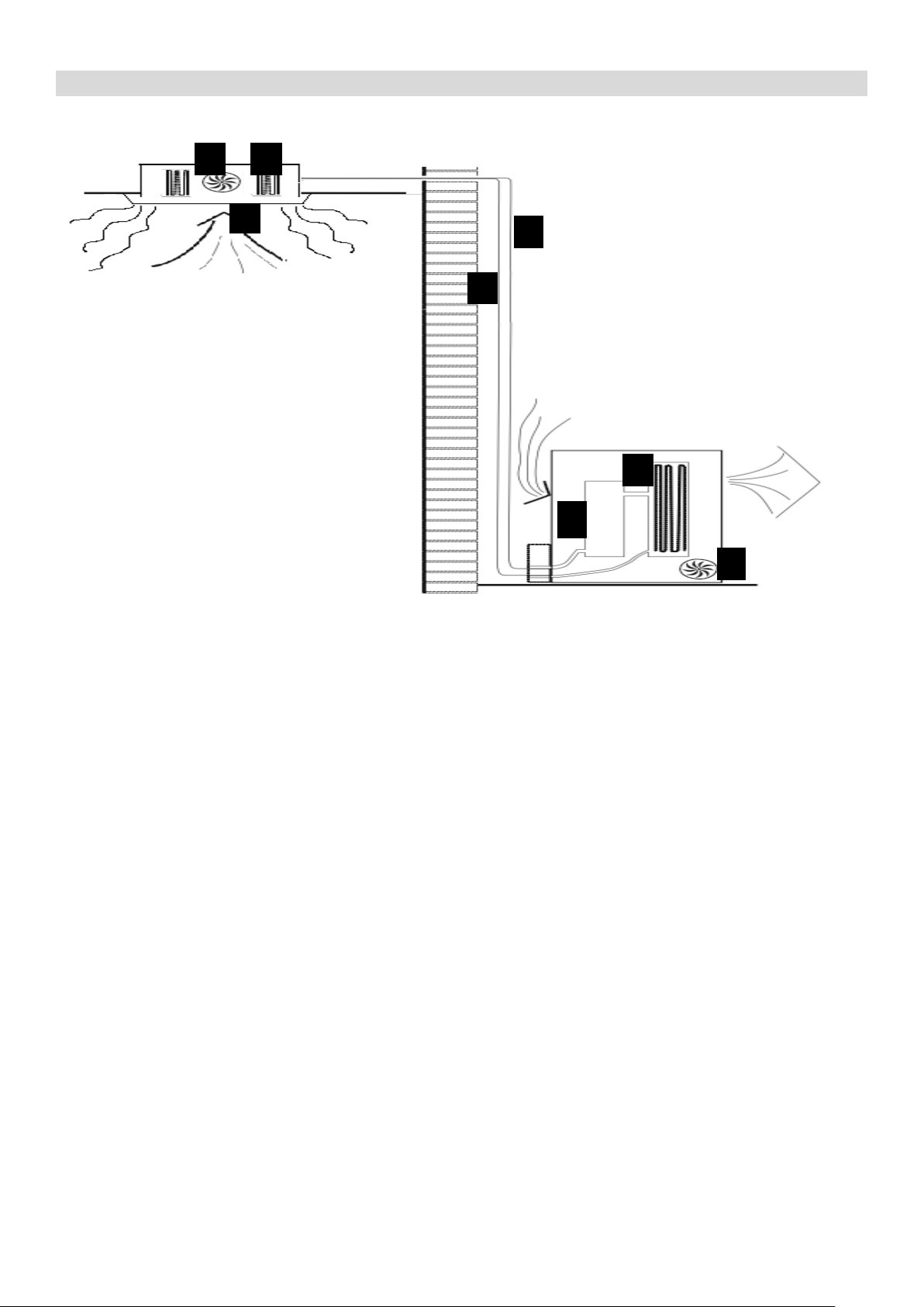
HOW AIR CONDITIONERS WORK
COOLING MODE
The compressor (6) in the external unit compresses the refrigerant into a high-temperature, highpressure gas. When this gas flows along the cooling fins of the condenser (7), heat is exuded and
the gas condenses into a liquid, which is then led to the evaporator (1) in the indoor unit. The liquid
expands into a gas at a low temperature and low pressure. This gas absorbs the warmth of the air
in the room, and a fan (3) draws the air through the filter and over the evaporator (1), blowing the
cooled air back into the room. The heat is moved to the compressor along with the gas. A fan (8)
draws air over the condenser and blows the warm air away.
1. Evaporator
2. Filter
3. Evaporator Fan
4. Gas Line
5. Liquid line
6. Compressor
7. Condenser
8. Condenser Fan
HEAT PUMP MODE
The system operates in reverse: the condenser works as an evaporator, the evaporator as
a condenser: warm air is blown into the room. It is ideal as a maintenance heating when
outside temperature is not too low and when the indoor temperature is more than 7°C.
DEHUMIDIFYING
As with cooling, the moisture in the air condenses on the cold evaporator at room temperature
acting as a powerful dehumidifier.
NOTE: This is a multisplit system and multiple indoor units are connected to a single
outdoor compressor. Please make sure that the indoor units are set to operate in the same
mode. Multiple indoor units connected to the same compressor cannot operate in different
modes at the same time although you are able to set different target room temperatures for
each unit. Fan only mode can be operated while other units are in heating or cooling.
31 4
568
7
Page 6
6
OPERATION
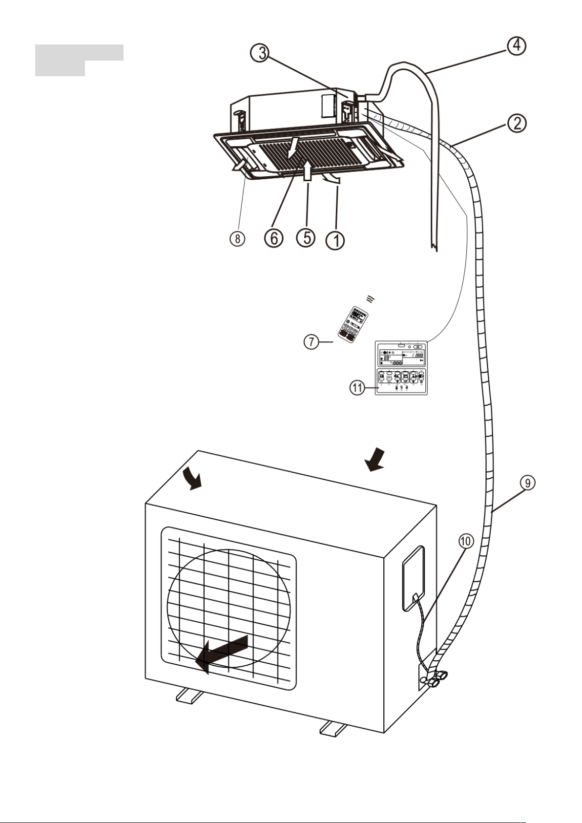
PARTS
INDOOR UNIT
OUTDOOR UNIT
1
Air Outlet
2
Refrigerant pipe junction
3
Uplift Pump
4
Drainage Pipe
5
Air Return
6
Filter
7
Remote Control
8
Louvre for airflow
9
Refrigerant pipes
10
Interconnecting Cable
11
Optional Wall Controller
Page 7
7
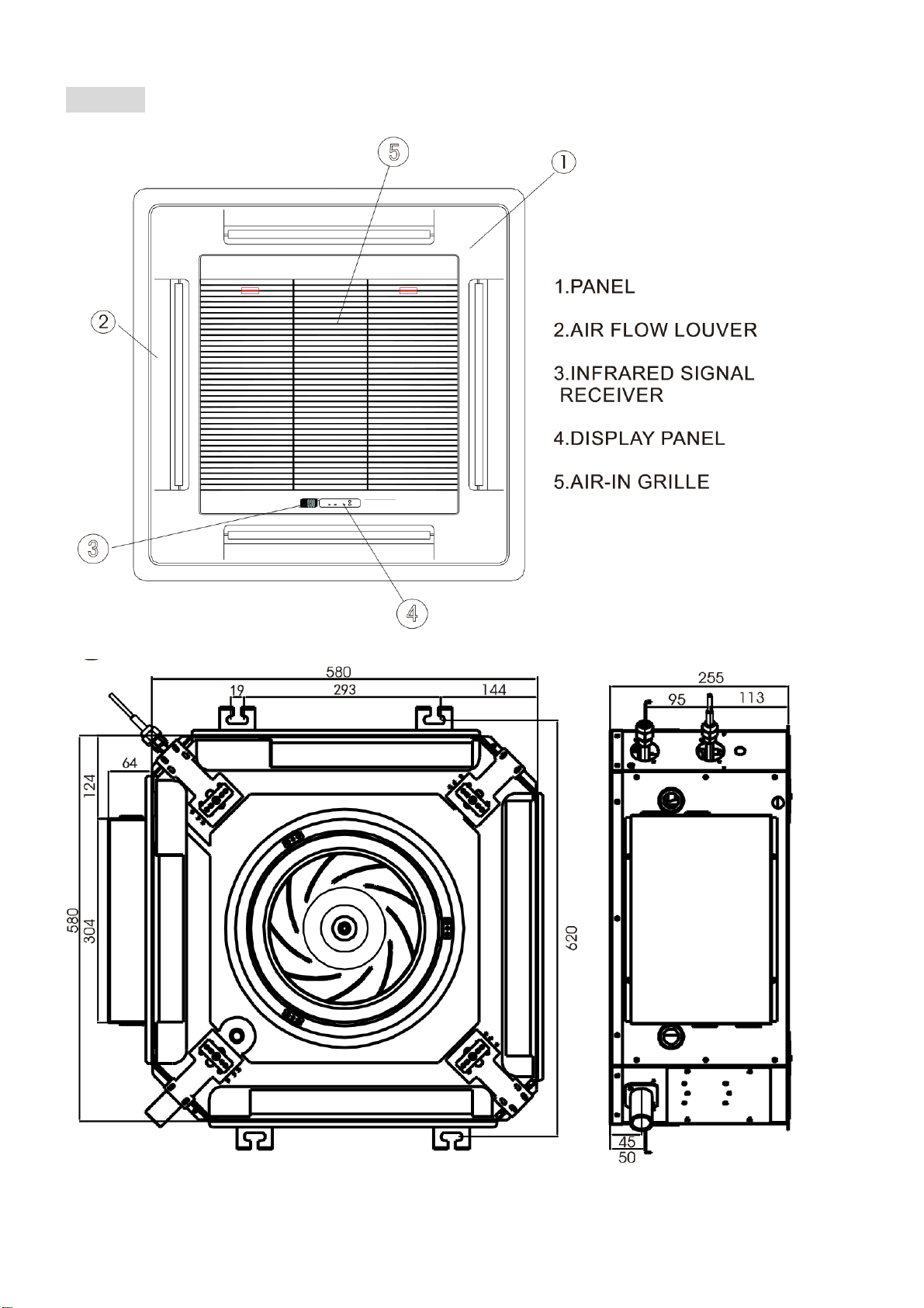
PANEL
Do not block the air inlets / outlets
on the cassette, as this will reduce
the units performance and may lead
to damage.
Page 8
8
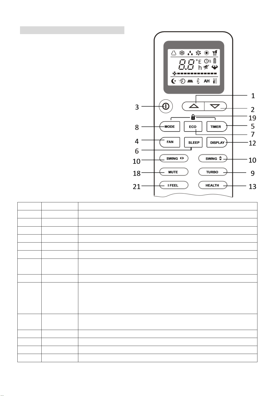
REMOTE CONTROL
The remote control has a range of up to
8m. Point the remote control at the
receiver in the interior unit. A beep
confirms that the remote control signal
has been received.
REMOTE OPERATION
Turn the appliance on using the ON/OFF
button. This activates the most recently
used setting.
The ON/OFF button also turns the air
conditioner off.
Please note that not all features are
available on all models.
No.
Button
Function
1
Up
Press to increase temperature
2
Down
Press to decrease temperature
3
ON/OFF
Press to turn on/off the unit
4
Fan
Press to select the fan speed LOW / MED / HIGH
5
Timer
Press to set the timer
6
Sleep
Press to activate the “SLEEP” function
7
Eco
In cooling mode, press to increase the set temperature by 2oC.
In heating mode, press to decrease the set temperature by 2oC
8
Mode
Press to select the desired operating mode
9
Turbo
Press to activate turbo mode. This will make the unit work its
hardest to quickly cool or heat the room for a period of 15 minutes.
The fan will be set to max, the temperature will be set to either
16oC in cooling mode or 31oC in heating mode.
10
Swing
Select the vertical direction of airflow (Horizontal direction not
adjustable on these models)
18
Mute
Press to turn off the beep when functions are selected
12
Display
Press to turn on/off the LED display
21
I Feel
Press to activate the follow me function
13
Health
Press to activate the antibacterial ioniser function
*
Page 9
9
oC/o
F
Temperature units can be changed on the remote by altering the switch under the battery
cover. Remove the batteries, move the switch to the desired units then replace the
batteries.
TEMPERATURE
The desired temperature is set with the up and/or down button, within the limits of the
thermostat: 16°C – 32°C.
Use the FAN SPEED button to set the fan speed at low, medium and high; or automatic (the
symbol on the display will flash). The fan speed in the automatic setting is determined by the
difference between the set temperature and the room temperature.
SETTING UP THE REMOTE
When batteries are first inserted into the remote or following changing the batteries, the remote
must be set up for COOLING AND HEATING or COOLING ONLY.
When the batteries are inserted the cool and heat symbols will alternate on the screen of the
remote. For HEATING AND COOLING press any button while the heat symbol is shown.
If the remote is set up for the wrong type of unit, simply remove the batteries and reinsert, before
following the step above.
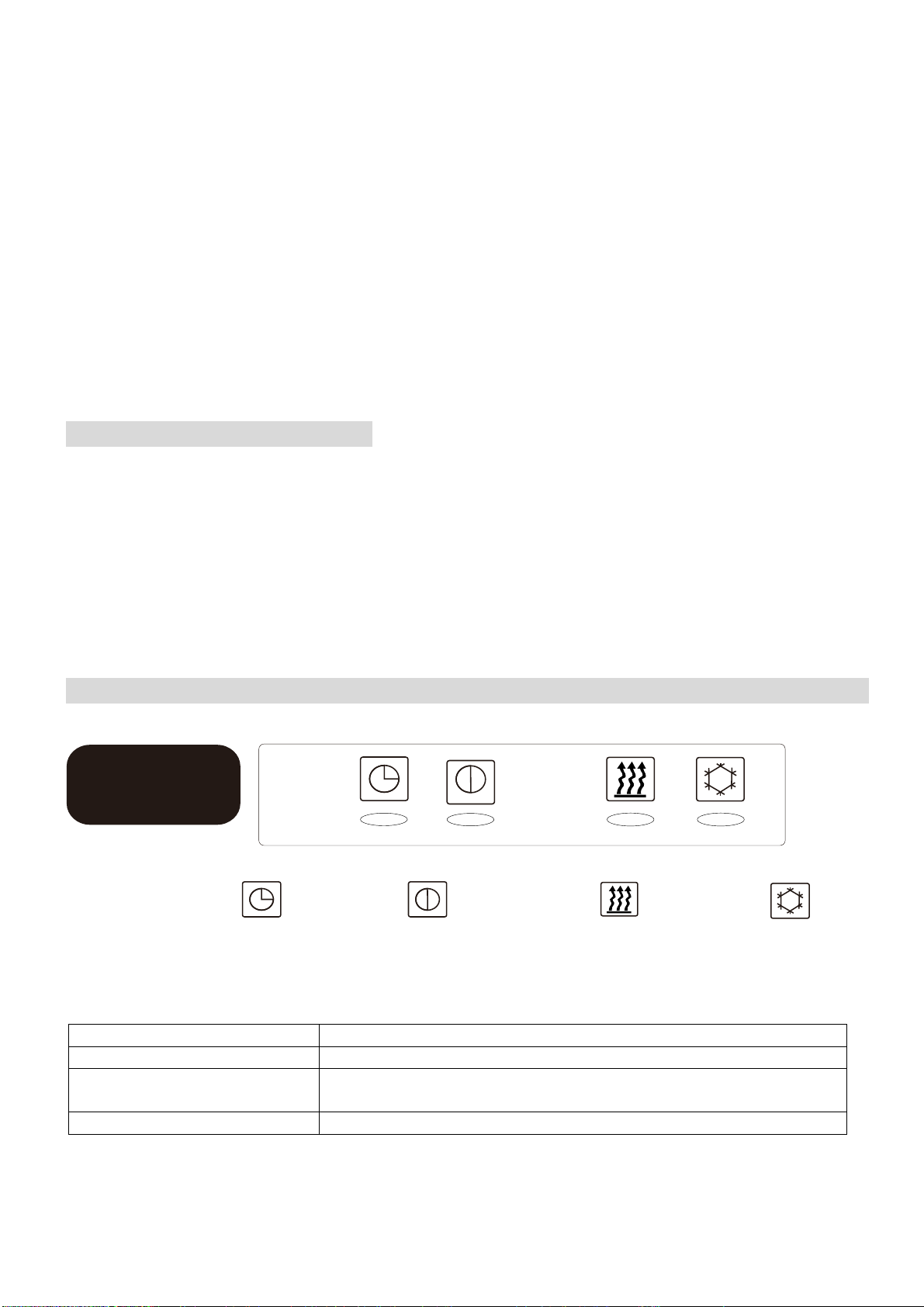
DISPLAY PANEL
ON when the unit is power on
ON when the water level is high
ON when the unit prevent cool air flowing in room.
Timer indicator
Operation indicator
PRE-DEF indic ator
Pump indicator
IR RECIEVER
TIMER
INDICATOR
OPERATION
INDICATOR
PRE-HEAT
INDICATOR
PUMP
INDICATOR
TIMER INDICATOR
Will illuminate when the timer is set
OPERATION INDICATOR
Will illuminate when the unit is turned on
PRE-HEAT INDICATOR
Will illuminate when the indoor unit is preheating the coils,
before warm air is expelled in heating mode.
PUMP INDICATOR
Will illuminate when the water level within the unit is high.
Page 10
10
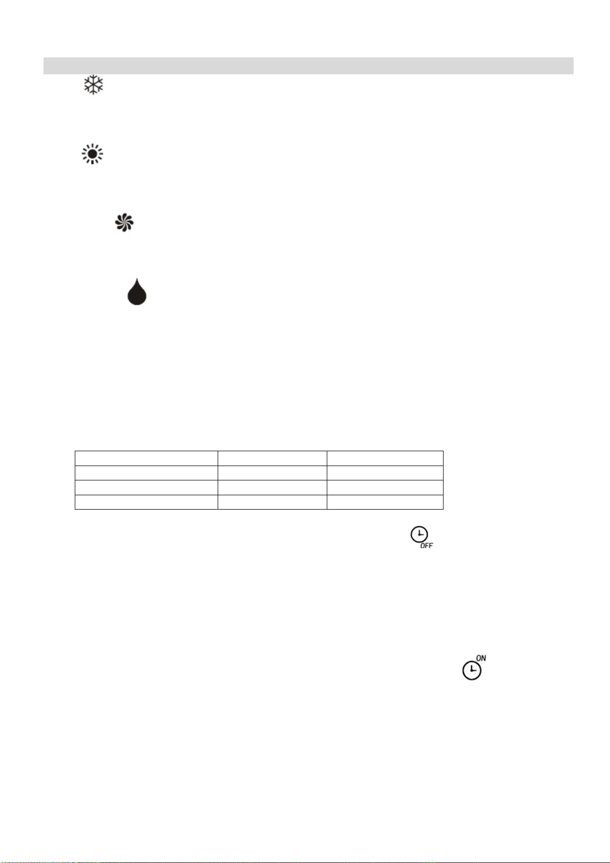
FUNCTIONS
COOL
1. Press the MODE button until the COOL indicator appears.
2. Set the desired temperature.
3.
Use the FAN button
to set the fan speed.
HEAT
1. Press the MODE button until the HEAT indicator appears
2. Set the desired temperature.
3. Use the FAN button to set the fan speed.
FAN MODE
1. Press MODE button until the FAN indicator appears.
2. The temperature settings are disabled in fan mode.
3. Use the FAN button to set the fan speed, cycling through LOW / MED / HIGH / AUTO.
DEHUMIDIFY
1. Press the MODE button until the dehumidify indicator appears.
2. The fan speed will always be low in this mode and the FAN button is disabled. In addition
the temperature cannot be adjusted in dehumidifying mode
AUTO MODE
1. Press the MODE button until the AUTO indicator appears.
2. The difference between the set temperature and room temperature determines how the air
conditioner operates: cool, heat, fan or dry. It is not possible to change the temperature in
this mode the unit will operate to achieve best performance. The operation logic is as
below.
Ambient Temperature
Operation Mode
Auto Temperature
˂20°C
Heating
23°C
20°C - 26°C
Dry
18°C
˃26°C
Cool
23°C
3. Use the FAN button to set the fan speed.
TIMER OFF FUNCTION (WHILE THE AIR CONDITIONER IS ON)
1. Press the MODE button until the symbol appears for the operation you want.
2. Set the desired temperature.
3. Use the FAN button to set the fan speed.
4. Press the TIMER button to set the running time required. Use the up and down buttons to
set the running time in 30 minute intervals (max 24 hours). Once the running time has
elapsed, the appliance will switch itself off. To cancel the timer function before the set time
has elapsed, press the TIMER button again.
TIMER ON FUNCTION (WHILE THE AIR CONDITIONER IS IN STANDBY)
1. The appliance is switched off in standby mode
2. Press the TIMER button to set the number of hours until switch on is required. Use the up
and down button set the number of hours in 30 min intervals (max 24 hours). Set the
desired operation, temperature, fan speed. Once the set time has elapsed, the appliance
will switch itself on. To turn off the timer function before the set time has elapsed, press the
TIMER button again.
Page 11
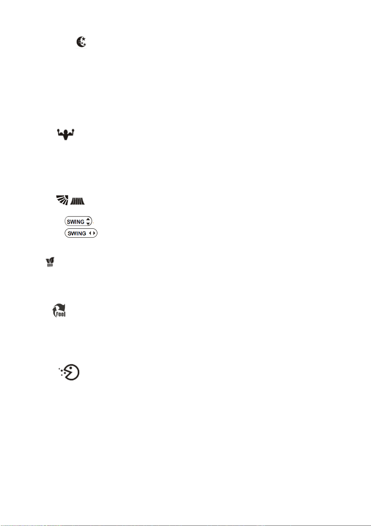
11
SLEEP MODE
1. Press the SLEEP button
2. Set the desired temperature.
3. Press the SLEEP button; The SLEEP indicator will appear on the display. Cancel the
sleep mode by pressing the button again.
4. The fan will operate at low speed.
5. The temperature is automatically altered by 1oC every hour for 2 hours. In cooling mode
the temperature will rise, in heating it will fall.
6. After 10 hours in Sleep mode the unit will power off automatically.
TURBO
1. Press the TURBO button until the Turbo symbol appears.
2. Set the desired temperature.
3. Use the FAN button to set the fan speed
4. Press the TURBO button. The fan and compressor will run at maximum speed for 15
minutes, before returning to their previously set levels.
SWING
1. Press the SWING buttons to control the fan direction.
2. The controls the horizontal air movement (up/down)
3. The button is not activated on this model, and the horizontal direction of the
airflow can be adjusted manually.
ECO
1. Press the ECO button to turn on the energy saving mode
2. In cooling mode, the desired temperature will increase by 2oC.
3. In heating mode, the desired temperature will decrease by 2oC.
IFEEL
1. Press the IFEEL button to activate the follow me mode.
2. In this mode the temperature of the unit will be set based on the temperature where the
remote is situated.
3. The remote will act as a mobile thermostat which controls the unit.
HEALTH
1. Press the Health button to activate the antibacterial ioniser function.
2. The ionizer helps to eliminate pollutants in the air.
NOTE
The functions listed are for the iQool range, and as such some features may not be available on
all models.
Page 12

12
IMPORTANT INFORMATION
AUTO RESTART
The air conditioner will automatically restart when electricity is restored after a power cut. If in
doubt, check the settings.
RANGE OF INTERNAL THERMOSTAT
The internal thermostat can be set at a desired temperature between 16 and 32°C. Note that
whether the desired value is achieved depends on the room size, temperature and insulation of
the room.
RANGE OF HEAT PUMP FUNCTION
The heat function can be used when the external ambient temperature is above -15°C. The
performance of the heat pump will degrade with lowering external temperatures. Please note the
performance will reduce when the outdoor temperature drops below 5°C.
CAPACITY
The required cooling or heating capacity depends greatly on the location and/or use of the room
where the air conditioner is installed. Strong sunlight and the presence of people, lights or
equipment creates an additional heat load. Normal living spaces require about 350 Btu per
square metre of floor surface. In strong sunlight or if other sources of heat are present, this may
be as much as 1200 Btu per sqm.
Tip: On warm days, let the air conditioner cool the room as much as possible during the night and
keep the temperature constant from night to daytime.
SELECTING THE OPERATIONAL MODE
This is a multisplit system and multiple indoor units are connected to a single outdoor
compressor. Please make sure that the indoor units are set to operate in the same mode. Multiple
indoor units connected to the same compressor cannot operate in different modes at the same
time although you are able to set different target room temperatures for each unit. Fan only mode
can be operated while other units are in heating or cooling.
Page 13

13
WIFI CONTROL
BEFORE YOU START
• Ensure your router provides a standard 2.4ghz connection.
• If your router is dual band ensure that both networks have different network names (SSID).
The provider of your router / ISP will be able to provide advice specific to your router.
• Once the app has been installed on your phone, turn off the data connection, and ensure
your phone is connected to your router via wifi.
DOWNLOAD THE APP TO YOUR PHONE
Please note that your air conditioner requires a good signal during the setup process. Your air
conditioner is designed to be connected to a 2.4ghz network, and the connection is set up using
the TCL “SMART LIFE” app. We would advise on using the QR codes below to ensure the
correct app is downloaded.
Android IOS
The unit can also be controlled using the “Smart Life” app by TUYA which is also available in the
app stores. We would advise on using the version above which is optimised for use with your air
conditioner as we cannot guarantee the correct functionality of all features with the TUYA app. If
you would prefer to use the TUYA app, please use the QR codes below
Android IOS
Page 14

14
ACTIVATING THE APP
The first time the app is
used, it will need
activating. To do this,
either press the scan
button, and scan the
QR code below, or
press “Enter Activation
Code” and enter the
activation code: TCL
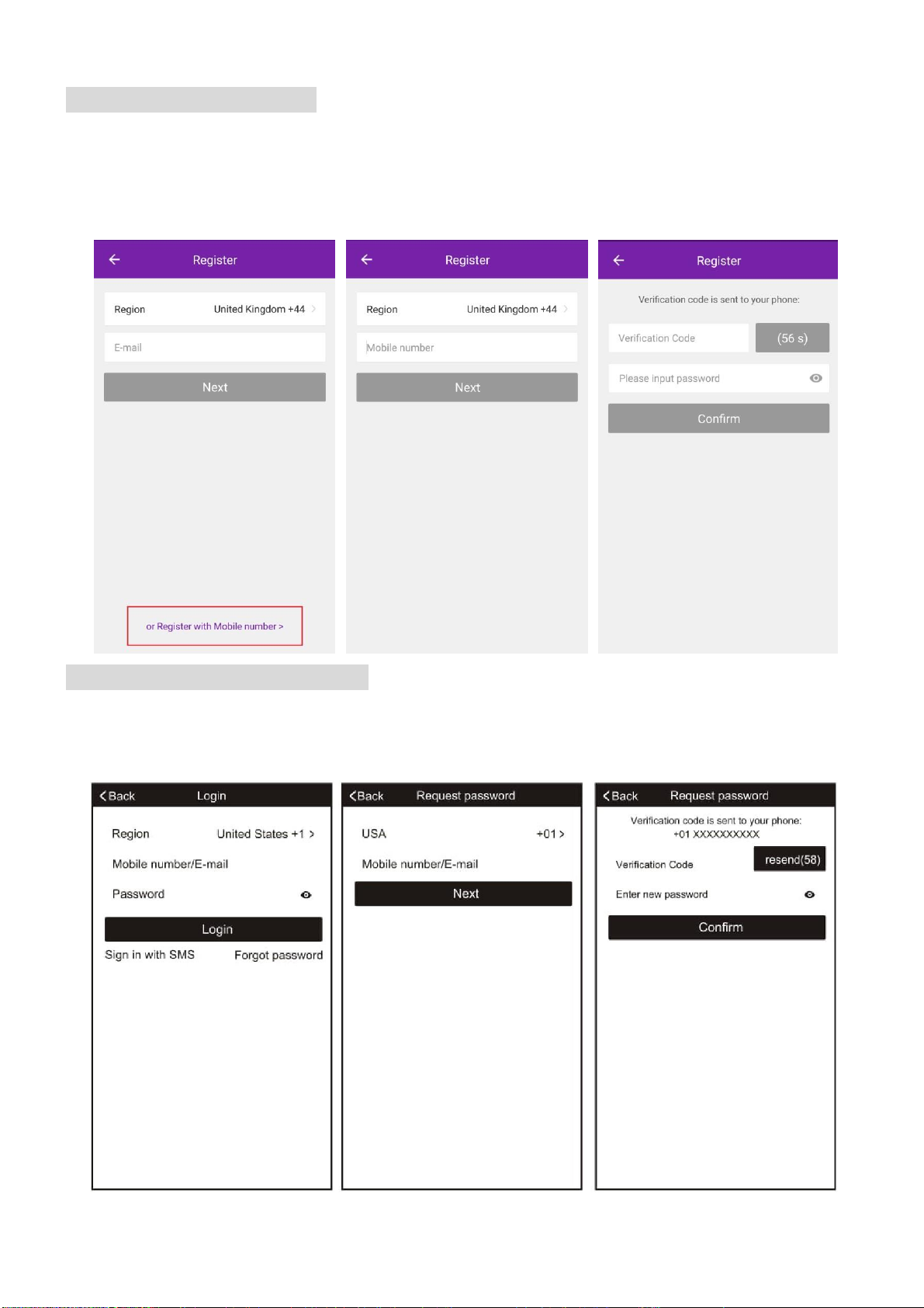
REGISTER THE APP
Upon the first use, an account will need to be registered. Click on
the “Register” button to enter the registration screen. The
account can be created by using either the default option of an
email address, or alternatively by SMS message using the
“Register with mobile number” option.
EMAIL
REGISTRATION
Enter your email address, and
Press next. In the password
box create a new password for
your account, before
pressing confirm. This
should be at least 6 characters
and include letters and
numbers.
Page 15
15
SMS REGISTRATION
Press on the option at the bottom of the screen to choose the option for registering with a mobile
number. You will receive an activation code via SMS. Enter the activation code into the
verification code box, before entering your new password in the box below.
Please note the password should be at least 6 characters and include letters and numbers.
Then press the confirm button to log in.
FORGOTTEN PASSWORD
Should the password for your account be forgotten, it is possible to use the “Forgot Password”
option which will allow you to enter the email address or telephone number used to register the
account, and a verification code will be sent to you via the method chosen.
Page 16

16
CONNECTION METHODS AVAILABLE FOR SETUP
The air conditioner has two different setup modes, CF (Quick Connection) and AP (Access
Point). The CF mode is a quick and simple way to set the unit up. The AP connection uses a
direct local wifi connection between your phone and the air conditioner to upload the network
details.
Before starting the setup, please ensure that your air conditioner is in the correct standby mode
for the connection type you are attempting, the display on the air conditioner will confirm the
current connection mode during setup.
Please note: Each indoor unit is classed as a separate device within the app and as such the
following connection process should be repeated for each indoor unit.
CHANGING BETWEEN CONNECTION TYPES
To change the unit between the two connection types, quickly press the display button on the
remote 6 times, and wait approx. 10 seconds until the new connection mode is displayed on the
panel of the air conditioner.
ADDING A DEVICE
1. Press the “Add device” button, which will bring up a screen to choose the device type.
2. Select “Split Air Conditioner” from the Device Type List.
3. The app will default to quick connection mode, and this can be changed by pressing the
button labelled AP Mode in the top right of the screen.
4. After ensuring that the air conditioner is also in the correct connection mode, follow the
relevant connection guide on the following pages.
Page 17

17
CONNECTING USING CF MODE (QUICK CONNECTION)
1. Ensure that the display on the air conditioner is displaying CF before pressing “Next Step”
(otherwise to change the connection mode: Quickly press the display button on the remote 6
times and wait 10 seconds until CF is displayed)
2. Select your Wifi router from the drop down list and enter the password (Please note the
password is case sensitive) before pressing next.
The app will automatically upload the connection information to the air conditioner, once the
connection is completed, a message will be displayed to confirm. On this page there is the
option to rename the air conditioner to something more relevant.
If the connection fails, please retry the connection, failing this try connecting using the AP mode
connection.
Page 18
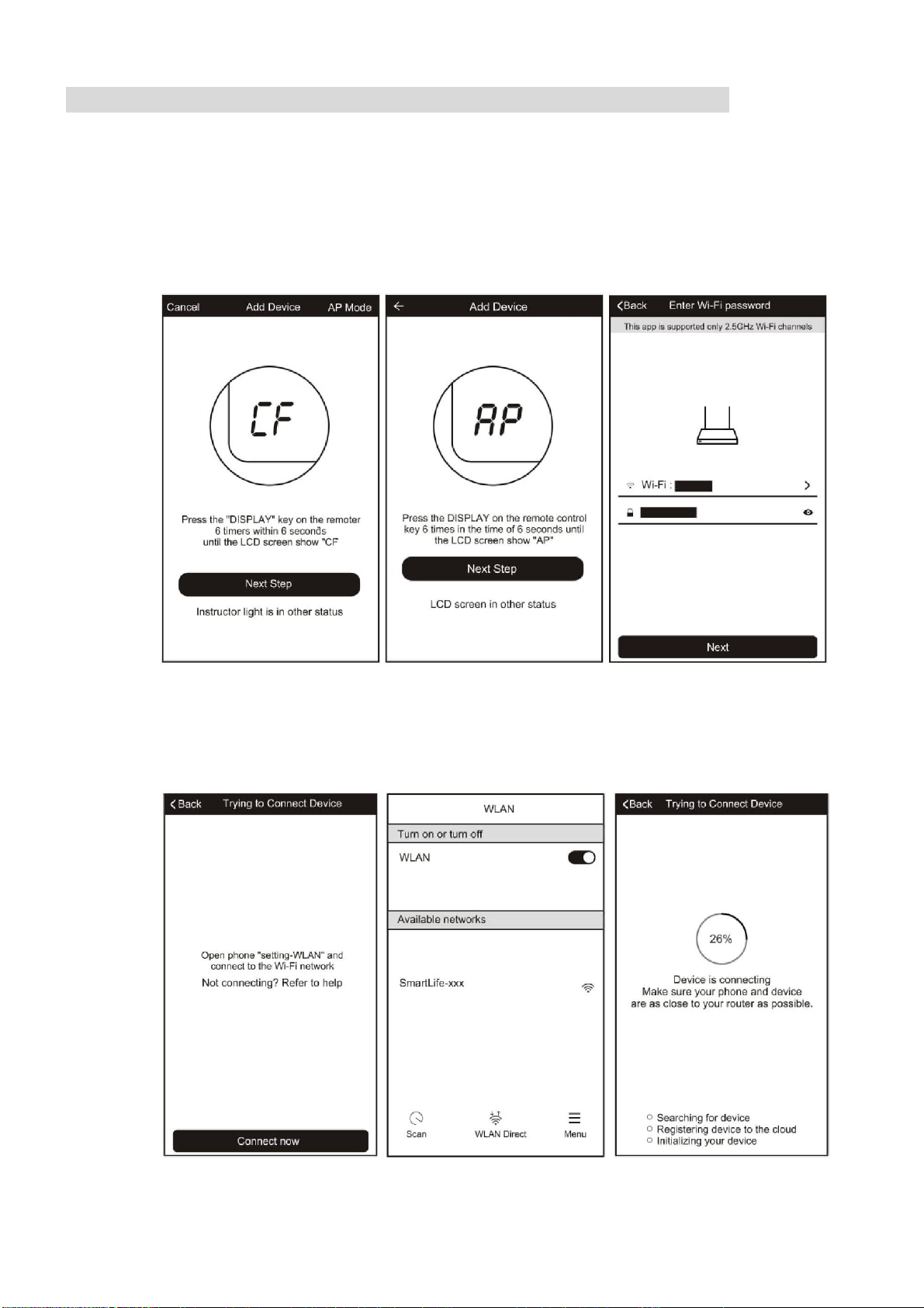
18
CONNECTING USING AP MODE (ALTERNATIVE METHOD)
1. Ensure that the screen on the air conditioner is displaying AP (otherwise to change the
connection mode: Quickly press the display button on the remote 6 times and wait 10
seconds until AP is displayed)
2. Press on the AP Mode button in the top right of the screen to change the app to AP mode
connection.
3. Select your Wifi router from the drop down list and enter the password (Please note the
password is case sensitive) before pressing next.
4. Connect your phone to the wifi network by leaving the app, and connecting to the Wifi
network created by the air conditioner “Smartlife-XXX”
5. Reopen the app and click on the “Connect now” button,
Page 19

19
The app will automatically upload the connection information to the air conditioner, once the
connection is completed, a message will be displayed to confirm. On this page there is the
option to rename the air conditioner to something more relevant.
If the connection fails, please retry the connection, failing this try connecting using the CF mode
connection.
Page 20

20
CONTROLLING YOUR DEVICE THROUGH THE APP
Now that your air conditioner is linked up to your network, you can control it from your phone.
Select your device in the device list to gain access to the controls for the device.
Use the + and – buttons to increase and decrease the desired temperature. The tabs on the
bottom of the screen should be used to change other settings.
Mode: Allows the operating mode to be changed between Feel, Heat, Dry, Cool and Fan.
Speed: Allows the fan speed to be changed between Auto, Low, Medium and High.
Function: Allows the Sleep, Turbo and Eco functions to be activated (See main manual for
description of the operation) and for vertical and horizontal swing on the louvres to be turned on
/ off (Not supported on all units)
Page 21

21
USING THE TIMER FUNCTION
The timer can be used to either set a time for the air
conditioner to turn on (and specify the settings it will run
with), or a time for the unit to turn off. Multiple timers can
be used together to build a schedule with on and off times.
1. Press the Timer button at the bottom right of the
screen.
2. To set a new timer, press the “Add Timer” button at
the bottom of the screen. If there is a timer already
programmed that you would like to amend, press
and hold the timer which requires amendment.
OFF TIMER:
1. Select Timer Off
2. Set the time the air conditioner should turn off 3.
Select which days the timer should operate
4. Press Save in the top right corner.
ON TIMER:
1. Select Timer On
2. Set the time the air conditioner should turn on
3. Select which days the unit should run on the auto timer.
4. Set the Mode, fan speed, desired temperature and function that the air conditioner
should run with.
5. Press Save in the top right corner.
Page 22

22
MORE SETTINGS
When on the main screen the three dots in the top right hand corner give you access to the
settings options for the app. This a number of extra options for modifying the name of the air
conditioner, and removing a device from the app.
Page 23

23
MAINTENANCE
FILTERS
Ensure the power is turned off to the unit before attempting to service the filters.
REMOVING THE GRILL
1. Push the two grill switched towards the centre to
unhook the grill before pulling the centre of the panel
downwards.
2. Care must be taken with the electrical
connectors (connecting the panel to the
main cassette) If necessery these
should be disconnected.
3. Hold the grill at a 45 angle to the unit
and lift to unhook from the rear of the
panel.
4. The filter can then be removed from the grill for cleaning.
CLEANING THE FILTERS
Clean the air filter with a vacuum cleaner or rinse with clean water.
If the filter is heavily soiled, a soft brush should be used with mild detergent.
Ensure the filter is fully dried before reinserting back into the grill and reattaching to the unit.
CLEANING THE OUTDOOR UNIT
While the unit is disconnected from power. Remove dirt and keep the air intake and exhaust
openings free of debris, etc. Cleaning with chemicals may cause damage.
Page 24

24
END OF SEASON
If the air conditioner is not going to be used for an extended period:
• Set in fan mode on a slightly warm day so that the inside of the appliance dries out.
• Switch off the power at the fuse box and remove the batteries from the remote control.
• Clean the filters.
• Remove the batteries from the remote control.
• Disconnect the power from the appliance
START OF SEASON
If the air conditioner is to be used again after an extended period:
• Check that the air intake and exhaust openings of the interior and exterior units are not
blocked. Remove any dirt or debris that has accumulated.
• Check that the filter is installed within the indoor unit and is clean.
• Check that the condensation outlet drains properly and there is no dirt or organic blockage
(otherwise leakage may occur)
• Install 2 AAA batteries in the remote control.
• Check that the wiring between the cassette and the panel is connected, and there is no
damage to the interconnecting wires.
• Turn the appliance on, set the time and desired setting.
REPLACING THE BATTERIES
• Remove the cover from the rear of the remote control.
• Replace the AAA batteries, ensuring the correct polarity.
• Reinstall the cover on the rear of the remote control.
• The display on the remote will start to alternate between the
HEAT and COOL symbols. Press any button on the remote when
the HEAT symbol is displayed to set the remote up for heating and
cooling.
• If nothing is displayed on the remote, try pressing the power
button. If still no response, check the polarity of the batteries and
try replacing.
Page 25

25
INSTALLATION GUIDE
SAFETY
Only qualified personnel should install this appliance. This installation manual is intended
for use by individuals possessing adequate backgrounds and qualifications in electrical,
electronic, refrigerant and mechanical fields. Any attempt to install or repair the appliance
may result in personal injury and property damage.
The manufacturer and retailer cannot be responsible for the interpretation of this
information, nor can it assume any liability in connection with its use.
The units are designed for permanent installation.
The equipment is designed for domestic or office use and we are not making any
endorsements for use in industrial or maritime environment.
Do not place near sources of heat, vapors, industrial machine oil or other flammable
gases.
High-frequency waves generated by radio equipment, welders and medical equipment
will interfere with the normal operation of the unit.
Install this device only when it complies with local/national legislation, ordinances and
standards.
Check the mains voltage and frequency. This unit is only suitable for an earthed electrical
supply, connection voltage 230 V~ / 50 Hz. The information, specifications and
parameter are subject to change due to technical modifications or improvement without
any prior notice. The accurate specifications are presented on the nameplate label.
Please read this installation manual completely before installing the product.
When the power cord is damaged, replacement work shall be performed by authorized
personnel only.
Installation work must be performed in accordance with all European, national and / or
local directives and standards and must be done by authorized personnel only.
Always make sure to wear the correct personal safety protections such as protective
eyewear, gloves, ear protection etc.
This air conditioner contains a refrigerant and can be classified as pressurized
equipment. Therefore always contact an authorized air conditioning engineer for
installation and maintenance of the air conditioner.
The air conditioner must be inspected and serviced on an annual basis by an authorised
air conditioning engineer.
Each indoor unit has a separate refrigerant circuit, and as such each circuit must be
individually pressure tested and purged during installation.
Rating: This unit must be only connected to a 220-240 V / 50 Hz earthed power source.
The unit should use an independent power supply switch and a separate circuit to other
electric appliances; use a power supply cable with specified section area to supply the
unit and equip the circuit with the correct rating of circuit breaker (with electric leak
protection function).
Installation must be in accordance with the regulations of the country where the unit is
used.
Diagrams and pictures provided within the manual are for guidance only. Due to continual
product development, if there is any variance between the manual and the product
received, the information provided on the product should be followed.
The outdoor unit must be mounted in an area sheltered from excessive rain and direct
Page 26

26
sunlight; We will not be liable for problems caused by installation in an unsuitable
location.
The appliance must be installed 2 - 3m above floor level.
The unit must be mounted with an earth wire with the specified section area and securely
mounted; do not connect the earth wire with the earth wire of gas pipelines, water
pipelines, arrester conductor or phone systems so as not to cause an electric shock risk.
The main power supply switch of unit should be placed out of reach of children so as not
to cause a hazard.
INDOOR UNIT POSITION
The air inlet and outlet vent should be away from any obstruction, ensuring that there is a good
airflow through the whole air-conditioned space. Select a position where the condensing water
can be easily drained out, and the indoor unit can be easily connected to outdoor unit. The ceiling
where the unit is fixed should be strong enough to withstand the full weight and vibration of the
unit. The unit should be accessible for service and maintenance. The height of the installed unit
should be more than 200cm from the floor. The air conditioner must not be installed in a wet
environment such as a bathroom, shower or swimming pool etc.
OUTDOOR UNIT POSITION
A convenient position, dry and well ventilated, outside of direct sunlight or strong winds, which is
not on a flood line and where noise and airflow does not cause interference or inconvenience.
Select a location where there are no obstructions to the inlet and outlet vents. The location
should be able to withstand the full weight and vibration of the outdoor unit and permit safe
installation.
Make sure that the outdoor unit is installed in compliance with the installation dimension diagram
with easy maintenance access. Select a place where it is out of reach of children. Do not block
utilities access or fire escapes.
The external unit must be lifted and put in place by two people.
NOTES:
1. Only use a power supply with the correct ratings, making sure the correct sized power cables
are used
2. The appliance shall be installed in accordance with standard wiring regulations by qualified
personnel
3. Only replace fuses according to their printed rating or corresponding pcb boards.
Page 27

27
TOOLS RECOMMENDED FOR INSTALLATION
Please note this is not an exhaustive list, and is provided as guidance for the most commonly
required tools.
Electric Drill
Hammer
Screwdrivers
Tape Measure
Core Hole Cutter
Spirit Level
Number 14 (7mm)
Masonry Drill
Pencil and Chalk
4 x M10 threaded
rods
Small Stepladder
7mm Wall Plugs
Protective Glasses
and Mask
Pipe and Cable
Detector
4 inch Plastic Ties
2 Inch Pipe Clips
Circuit Breaker
Garden Gloves
Dust Sheets
Foam Filler
Silicone Sealant
Page 28

28
INSTALLATION OF THE INDOOR CASSETTE UNIT
Where possible the following areas should be avoided to avoid potential problems with the
appliance and/or safety risks:
1. Where flammable gas is likely to be in the air.
2. Where the air has a high salt content
3. Where caustic gasses are likely to be in the air.
4. Which is unable to safely bear the weight of the unit
5. With high levels of electromagnetic interference.
6. Where the unit may be subjected to acid or alkaline solutions.
7. With high levels of humidity.
Select the installation location taking consideration of the following:
1. Route of the pipework / wiring
2. Access to the upper parts of the unit for connection of the pipework/wiring after hanging
the unit
3. Ability of the area to support the weight of the unit.
Before hanging the unit the
refrigerant pipes, drain pipe
and connection wires
should be led to the
location of the outdoor unit.
Confirm the size of the
indoor unit and ceiling
opening using the
supplied installation
template.
SPACE AROUND THE UNIT
The following space must be
left around the unit.
1. At least 1m to each side.
2. At least 33cm between upper
side of ceiling and structure
above.
3. At least 5cm above the unit
to any structure or
obstruction.
Page 29

29
PREPARATION WORK ON THE CEILING
The indoor cassette unit is designed to be supported by 4 x threaded rods, connecting it to a solid
structure above.
The unit must be installed in accordance with current building regulations and the Installation
method should be adjusted depending on the structure of the ceiling. If in any doubt about what
installation method is suitable, independent advice should be sought.
After opening a hole, ensure that the ceiling is horizontal and strong to prevent vibration during
operation. Reinforcement of the ceiling around the opening may be necessary.
If beams require cutting to accommodate the unit, the remaining beams around the area should
be reinforced to compensate for the extra weight they are now supporting.
WOODEN CONSTRUCTION
Fix a square length of timber over the roof
beam and install the hanging screw bolts into it.
NEW CONCRETE PANELS
FINISHED CONCRETE PANELS
Install the hanging hook using expandable bolts
into the concrete to a depth of at least 45mm to
prevent them coming use during operation.
STEEL ROOF BEAM STRUCTURE
Hanging screw bolt
Hanging bolts
Supporting
angle steel
Blade shape
Slide insertion
Steel bar
Pipe hanging and
embedding screw bolt
Timber over the beam
Roof beam
Hanging Screw Bolt
Ceiling
Page 30

30
HANGING THE CASSETTE UNIT
Adjust the under side of the gasket
so it sits 90mm above the ceiling.
Overhang the cassette unit above
the ceiling, slotting the bars into the
brackets on the cassette unit and
tightening into position, ensuring
that the unit is level.
Hanging Bolt
Nut (Up Side)
Gasket (Up Side)
Installing Ear
Nut (Under Side)
Gasket (Under Side)
Underside of Ceiling
90mm
Page 31

31
DRAINAGE PIPE INSTALLATION
Ensure that the drainage pipe used has sufficient insulation to prevent condensation forming
on the pipework.
As the drain is gravity fed, it must decline at a slight angle (2/100) with no twisting or bending
to aid drainage.
The maximum length of the drain pipe must not exceed 20m, and must be suitably supported
to prevent bumps and bends.
Ensure that pressure is not placed on the pipe, as this may restrict the flow of condensate from
the unit.
The flexible hose must be mounted horizontally.
We advise on the following materials to be used:
Drain Pipe
Polyvinyl chloride pipe (32mm outer diameter)
Heat Insulation
Foamed polyethylene insulation plate (10mm thickness)
Use polyvinyl chloride glue at any connection points to prevent water leakage
Place glue over the front 40mm of the pipe before inserting it into the transparent pipe.
Allow 10 minutes for the glue to dry before placing any pressure on it.
Core shift adjustment
Bend 45 (Maximum)
Hose band
Flexible Hose
Indoor Unit
20
45
Support
Bend
Up and Down
Fold
As long as possible min10mm
Lean Downward
over 2/100
Lean Downward over 2/100
Page 32

32
DRAINAGE UPWARDS
Upon leaving the unit the drainage pipe can
have an initial horizontal lift of upto 360mm,
before starting the downwards inclination
indicated on the previous page. This must be
within 100mm of the drainage pipe leaving
the cassette unit.
DRAINAGE TEST
Once the drain pipe has been fully installed, the pipework should be initially be visually checked.
Once visually checked, an operation test can be conducted.
1. Ensure power is not connected to the unit.
2. Remove the water tank cover and insert 600ml of water, ensuring that it does not touch the
drain pump motor.
3. Disconnect the water level switch.
4. Connect the power to the unit, and the drain pump should start immediately.
5. Allow to run for 1 minute.
6. Following the test, disconnect the power and reconnect the water level switch.
Cover
L
N
Below 360mm Below 600mm
Below 100mm
Indoor Unit
Ceiling
Drainage Pipe
Page 33

33
PANEL INSTALLATION
The panel should be installed after the pipwork and wiring have been connected.
Following installation ensure that the gaps between the panel and the ceiling are sealed to
prevent air and liquid leakage.
1. Push the two grill switched towards the
centre to unhook the grill before pulling the
centre of the panel downwards to remove it
from the panel.
2. Hold the grill at a 45 angle to the unit and lift
to unhook from the rear of the panel.
3. Hold the panel against the cassette
unit, lining up the red arrow on the
electrical box with the one on the
panel, before loosely fastening with
the M6 bolts.
4. Connect the cables for the step
motors and display panel to the
cassette following the wiring diagram
provided, ensuring that the cables will
not get trapped when tightening the
panel.
5. If the optional wired display panel is also to be installed, it should be also be connected to the
cassette at this point.
6. Check the position of the panel before fully tightening the bolts, so that the panel is flush to the
cassette unit.
7. Reattach the Grill to the panel following the reverse of removal.
8. If there is a gap between the panel and the ceiling after tightening the screws, readjust the
height of the cassette, ensuring it is kept level.
Page 34

34
INSTALLATION OF THE OUTDOOR UNIT
Try to move the product to the installation location in its original packaging
As the gravity center of the unit is not at the installation center, special caution should be taken
when using hoisting cables to lift it up
During transport, the outdoor unit must not be tilted to over 45 degrees (also do not store the unit
horizontally.
Use expansion bolts to fix the mounting supports on the wall;
Use bolts and nuts to fix the outdoor unit firmly on the supports and keep on the same level;
If the unit is installed on the wall or at the rooftop, the supports have to be firmly fixed so as to
resist earthquakes or strong wind.
Dimensions for parallel units installations
300mm(1')min
CONDENSATE DRAINAGE OF THE OUTDOOR UNIT
When operating in heating mode condensate
will collect and drain through the base of the
outdoor unit. The air conditioner is supplied with
an elbow joint which can be connected to the
underside of the outdoor unit for drainage.
1. Connect the elbow joint to the drainage hole
on the underside of the outdoor unit.
2. Connect a drain hose (not supplied) to the
elbow joint and run downhill to your chosen
drainage point.
Please note: The drainage is gravity fed, and so
must run downhill.
Page 35

35
REFRIGERANT PIPE INSTALLATION
The system is not provided with pipework or interconnecting wires, which should be supplied by
the engineer and cut to the appropriate size. The unit is precharged for 5 metres of pipework and
refrigerant must be added if the pipe length is more than 5 metres. This operation can only be
performed by a professional F-Gas engineer, for the additional gas amount, see the below:
FLARING THE PIPES
1. Cut the refrigerant pipe to the correct length using a pipe cutter.
2. Ensure the end of the pipe is smooth.
3. Slide the connecting nut onto the pipe before flaring with an appropriate tool, to create a
flare with the requirements below.
Diameter
Additional Refrigerant
Max pipe length
Max difference
in Height
Liquid Side
Φ6.35 (1/4”)
(Total length of pipe run
– 5 meters) x 15 g
15m
10m
Gas Side
Φ9.52 (3/8”)
Page 36

36
NOTES:
The copper pipe used in the refrigeration lines are very soft, high pressure copper and prone to
get damaged if not handled correctly. Try to avoid bending or stretching the pipework. Always
ensure the pipes are protected when running through the wall to help prevent damage to the
pipes.
To keep the allowed
bending radius please
make th e packed soft
pipes vertical before
extending
Please do not extend only
one side of the packed soft
pipes.
Please make use of
semicircle pulley to keep the
allowed bending angle
Extreme bending could
damage the pipes
Please use a twisting
wheel to avoid improper
bending.
Over bent soft pipes will lead
to irregular bending
Please use rigid elbow to
keep the bending angle
while soft pipes operating.
Undersize bending will
damage the soft pipe.
Please kee p the minimum
bending angle while
installing
Do not use short sharp
angle bends.
Page 37

37
STANDARD PIPELINES CONNECTION & AIR PURGING
No dust or any other particles, air or moisture should be allowed to enter the air conditioning
system. Careful attention should be paid when pipeline connection for outdoor unit is made. Try
to avoid repeated curves as much as possible; otherwise damage to the copper pipes may occur.
Suitable wrenches should be used when the pipeline connection is done so as to ensure
appropriate torque (refer to following torque table).
Excessive torque action might damage the joints while too little torque might lead to leakage.
Torque based upon the wrench to be used
Follow the procedures below:
1. Remove the dust caps from the indoor and outdoor units and the connecting pipe.
2. Align the joint of the connecting pipe between the indoor and outdoor and tighten the
connecting nut by hand to prevent cross threading. Secure them with a wrench, applying
the maximum torque as shown in the table above.
3. Pressure test and vacuum pump the pipework for each refrigerant circuit.
4. Remove the two valve core caps from the outdoor unit and turn on the high and low
pressure valve cores with an socket wrench, then tighten the two valve core caps of the
outdoor unit. Finally you can wrap hot insulating tape around the joints of indoor and
outdoor units
Copper pipe diam.
Tightening torque
Strengthened tightening torque
6.35(1/4")
160kgf.cm(63kgf.inch)
200kgf.cm(79kgf.inch)
9.52(3/8")
300kgf.cm(118kgf.inch)
350kgf.cm(138kgf.inch)
Page 38

38
AIR PURGING WITH VACUUM
PUMP
Please note this should be completed
for each refrigerant circuit (each
indoor unit)
1. Check that pipelines connection
have been properly connected,
remove the charging port cap, and
connect the manifold gauge and
the vacuum pump to the charging
valve using service hoses as
shown
2. Open the valve on the low-
pressure side of the manifold
gauge, then run the vacuum pump.
Vacuum the indoor unit and the
connecting pipes until the pressure
in them lowers to below 1.5mmHG
(The operation time for vacuuming
is about 10 minutes). When the
desired vacuum is reached, close
the low pressure valve on the
manifold and stop the vacuum
pump.
3. Disconnect the service hoses and
fit the cap to the charging valve.
4. Remove the blank caps, and fully
opens the spindles of the 2-way
and 3-ways valves with a service
valve wrench.
5. Tighten the blank caps of the 2-
way and 3-ways valves, applying
the torque listed in the table above.
GAS LEAKAGE INSPECTION
After the pipeline connection is done, use a leakage inspection device to carefully check
if there is any leakage at the joints. This is an important step to ensure the quality of
installation. Once a leak is detected, proper action should be taken immediately.
Page 39

39
ELECTRICAL CONNECTION OF THE AIR CONDITIONER
The electrical connections can be found under the protective plastic cover. Remove
this from the side of the outdoor unit to gain access to the electrical connections.
Connect the indoor power and control wires with the matching outdoor wire as per
the electrical diagram.
Do not attempt to connect the wires in a different way to the diagram on the air
conditioner as this could damage the unit and invalidate the warranty.
Secure the wires and replace the cover before operating the unit.
The appliance should be installed in accordance with national wiring regulations.
If the supply cord is damaged, it must be replaced by the manufacturer, its service
agent or a suitably qualified person in order to avoid a hazard.
The unit is designed to be hard wired and a suitable switch with a contact separation
of at least 3mm in all poles must be added to the fixed wiring.
The air conditioner electrical wiring must follow the specific country regulations. If
power cord is damaged must be replace by a qualified electrician.
Page 40

40
ELECTRICAL WIRING DIAGRAMS
Please note: The diagrams provided in the manual are for guidance only. Due to continual product development the
diagrams provided on the units themselves should be followed where any discrepancies are found
Connection of Panel to the
Cassette
Indoor PCB
Page 41

41
iQool-C3MS9K9K9K Outdoor PCB
iQool-C2MS12K12K Outdoor PCB
Outdoor PCB
Outdoor PCB
Page 42

42
TROUBLESHOOTING AND SELF DIAGNOSIS
MALFUNCTION
POSSIBLE CAUSE
The appliance
does not
operate
Power failure
Damaged indoor/outdoor unit fan motor
Faulty compressor thermomagnetic circuit breaker
Faulty protective device or fuses
Loose connections
Self protection in adverse conditions
Voltage higher / lower than the voltage range
Active TIMER-ON function
Damaged electronic control board
Strange odour
Air filter dirty
Noise of running
water
Back flow of liquid in the refrigerant circulation
A fine mist
comes from
the air outlet
This occurs when the air in the room becomes very cold, for example
in the COOLING or DEHUMIDIFYING modes.
A strange noise
can be heard
This noise is made by the expansion or contraction of the front panel
due to variations in temperature and does not indicate a problem.
Insufficient
airflow, either
hot or cold
Inappropriate temperature setting.
Air inlet or outlet of indoor or outdoor unit has been blocked.
Air filter is blocked.
Fan speed set at minimum.
Other sources of heat in the room.
No refrigerant.
The appliance
does not
respond to
commands
Remote control is not near enough to indoor unit.
Battery in Remote controller may have been exhausted..
Obstacles between remote control and signal receiver in indoor unit.
The display is
off
Active LED function
Power failure
Remote cannot
select heating
mode.
Remove the batteries from the remote and follow the guide for
setting up the remote.
Switch off the air conditioner immediately and cut off the power supply in the
event of:
Strange noises during operation.
Faulty electronic control board
Faulty fuses or switches.
Spraying water or objects inside the appliance.
Overheated cables.
Very strong smells coming from the appliance.
Page 43

43
ERROR SIGNALS ON THE DISPLAY
In case of error, the display on the indoor unit shown the following error codes:
Error Code
Failure type
E0
Indoor and outdoor communication failure
EC
Outdoor communication failure
E1
Indoor room temperature sensor
E2
Indoor coil temperature sensor
E3
Outdoor coil temperature sensor
E4
System abnormity
E5
Model configuration wrong
E6
Indoor fan motor fault
E7
Outdoor temperature sensor
E8
Exhaust temp. sensor
E9
IPM drive and module fault
EA
Current sensor fault
Ed
Indoor EEPROM fault
EC
Outdoor Communication fault
EE
Outdoor EEPROM fault
EF
Outdoor fan motor fault (DC motor)
EH
Outdoor suction temperature sensor fault
En
Outdoor gas pipe temperature sensor fault
EP
Temp. switch fault ( on top of the compressor)
EU
Voltage sensor fault
Ey
Outdoor liquid pipe temperature sensor fault
Protection Display Code List
PA
Indoor run mode conflict
P1
Overvoltage /lower voltage protection
P2
Overcurrent protection
P4
Exhaust over temperature protection
P5
Too cool protection in cooling mode
P6
Overheat protection in cooling mode
P7
Overheat protection in heating mode
P8
Outdoor over temperature
/ lower temperature protection
P9
Drive protection (software control )
P0
Module protection (hardware control)
Page 44

44
OUTDOOR UNIT FAULT CODES
The outdoor unit has an LED on the power board. This LED will be illuminated when
the compressor is running and blink 1s on and 1s off when the compressor is in
standby. If there is a fault on the outdoor unit, it will blink on and off for half a second at
a time, followed by a 3s gap. The number of consecutive blinks will show the fault as
per the table below:
No. of blinks
Fault
1
IPM protection
2
Over voltage /lower voltage
3
Overcurrent
4
Exhaust over temperature protection
5
Outdoor coil over temperature protection
6
Drive fault and protection (V1,VP1)
7
Communication fault with indoor unit
8
Compressor overheat fault (compressor top switch)
9
Short-circuit / open-circuit fault of outdoor temperature sensor
10
Short circuit / open-circuit fault of outdoor heat exchanger temperature
sensor
11
Short-circuit / open-circuit fault of exhaust temperature sensor
12
Voltage sensor fault
13
Current sensor fault
14
IPM fault
15
Communication fault between power source board and IPM
16
No feedback from DC fan motor(outdoor unit)
17
Defrost state
Page 45

45
WIFI CONTROL TROUBLESHOOTING
Description
Possible Cause
Air conditioner
can’t be configured
successfully
4. Check the mobile device is connected to WIFI
5. Check the AC is connected
6. Check that any firewall or other restrictions are causing
problems
7. Check the router is functioning normally
8. Check that the router isn’t blocking the App
Mobile device can’t
control the air
conditioner
The app displays “Identification failed”. This indicates that the AC
has been reset and the mobile device has lost contact with the AC.
Reconnect the device following the above instructions. If this fails,
delete the AC from your devices list and start the install process
from the beginning.
Mobile device can’t
find AC
The app displays “Air conditioner out of line”. Check the below:
1. The AC has been reconfigured
2. The AC is not receiving power
3. The router is not powered on
4. The AC can’t connect to router
5. The AC can’t connect to network through the router
6. The mobile device can’t connect to the router
7. The mobile device can’t connect to a network (when being
used remotely)
Page 46

46
TECHNICAL SPECIFICATION
Model
iQool-C3MS9K9K9K
iQool-C2MS12K12K
Rated voltage and frequency (Ph-V-Hz)
1Ph/220-240V~/50Hz
1Ph/220-240V~/50Hz
Fuse Required
13A
13A
Mode
Cooling
Heating
Cooling
Heating
Rated capacity (W)
Single
2637
2637
3517
3517
Double / Triple
8200
(3100~8790)
9050
(2550~9800)
6150
(2800~6600)
6600
(2450~6900)
Power input (W)
Single
816
730
1083
970
Double / Triple
2500
(410~2700)
2200
(510~2850)
1880
(350~2100)
1710
(420~2050)
Current input (A)
Single
3.83
4.42
5.07
4.55
Double / Triple
11.3
(1.86~12.3)
9.8
(2.32~12.4)
8.5
(1.6~9.5)
7.8
(1.9~9.3)
SEER/SCOP(W/W)
6.1/A++
4.0/A+
6.1/A++
4.0/A+
Nominal load (kW)
8.20
9.05
6.15
6.60
Balance point temperature heating (oC)
/
-7 / -7
Min. outdoor operating temperature (oC)
/
-15 / -15
Thermostat-off mode (W)
161
129 Standby mode (W)
6
4 Off mode (W)
0
0 Annual consumption (kW)
470
2733
352
2098
Number of indoor units supplied
2
3
Max number of indoor units
3
4
Copper Pipe Type length
5m
5m
Liquid side / Gas side (mm/inch)
6.35 (1/4) + 9.52 (3/8)
6.35 (1/4) + 9.52 (3/8)
Max. refrigerant pipe length for each unit
15m
15m
Max. elevation
10m
10m
Interconnecting Cable
4×0.75mm²
4×0.75mm²
Fuse Rating
5A on indoor PCB
5A on indoor PCB
Moisture Removal (L/h)
0.9 L/h per one unit
0.9 L/h per one unit
Indoor
Air Flow (m3/h)
500
600
Dimensions (L*W*H) (mm)
574×574×250
574×574×250
Packaging (L*W*H (mm)
725×725×330
725×725×330
Net / Gross weight (Kg)
20/24
20/24
Noise – Sound pressure level
(MPa)
36~42
36~42
Noise – Sound power level
(dB/A)
46~52
46~52
Page 47

47
Outdoor
Dimension (L*W*H) (mm)
940×910×340
900x660x310
Packaging (L*W*H) (mm)
1030×950×430
1050x715x425
Net / Gross Weight (Kg)
68/80
50/55
Noise – Sound pressure level
(dB/A)
60
58
Noise – Sound power level
(dB/A)
70
68
Refrigerant type/weight
R410A/2800g
R410A/2300g
Defrost mode
Automatic defrosting
Automatic defrosting
Applicable climate types
Cooling (0oC – 53oC)
Heating(-20oC – 30oC)
Cooling (0oC – 53oC)
Heating(-20oC – 30oC)
Due to continuous product development process specification may change.
These units contain a gas governed by F-Gas regulations. The gas must be handled by
qualified F-Gas engineers.
APPENDIX
Disposal: Do not dispose this product as unsorted municipal waste. Collection
of such waste must be handled separately as special treatment is necessary.
Recycling facilities are now available for all customers at which you can
deposit your old electrical products. Customers will be able to take any old
electrical equipment to participating sites run by their local councils. Please
remember that this equipment will be further handled during the recycling
process, so please be considerate when depositing your equipment. Please
contact the local council for details of your local household waste recycling
centres.
Page 48

48
WARRANTY INFORMATION
TCL guarantee provides cover against material or manufacturing faults.
This means that if your air conditioner develops a fault during the guarantee
period, we will arrange for it to be repaired or replaced.
Faults arising from a faulty installation are specifically excluded.
The system must be serviced annually by qualified personnel.
This unit must be operated under conditions as recommended in this user
manual, at voltages indicated on the unit. Any attempts made to service or modify
the unit by unqualified person, will render this WARRANTY VOID.
This warranty is in addition to, and does not affect, your statutory rights.
Our warranty is RTB warranty and cover parts and labour only.
We recommend that you note the details of your purchase below and retain your original
proof of purchase receipt with this manual. Keep these documents safe in the event of a
warranty claim.
Purchase Date: _____________________________
Retailer name: _____________________________
Model number: _____________________________
Serial number: _____________________________
Installation Date: _____________________________
Installer name: _____________________________
Service Date: _____________________________
Engineer/ Company name: _____________________________
TCL UK SUPPORT
Please, for your own convenience, check the troubleshooting guide before calling the service
line.
If the unit still fails to operate call: 0871 620 1057 or complete the online form
Office hours: 9AM - 5PM Monday to Friday
TCL AIR CONDITIONING
Unit J6, Lowfields Business Park
Lowfields Way, Elland
West Yorkshire, HX5 9DA
V20190604
 Loading...