

Page 1
Page 2
Page 3

íð
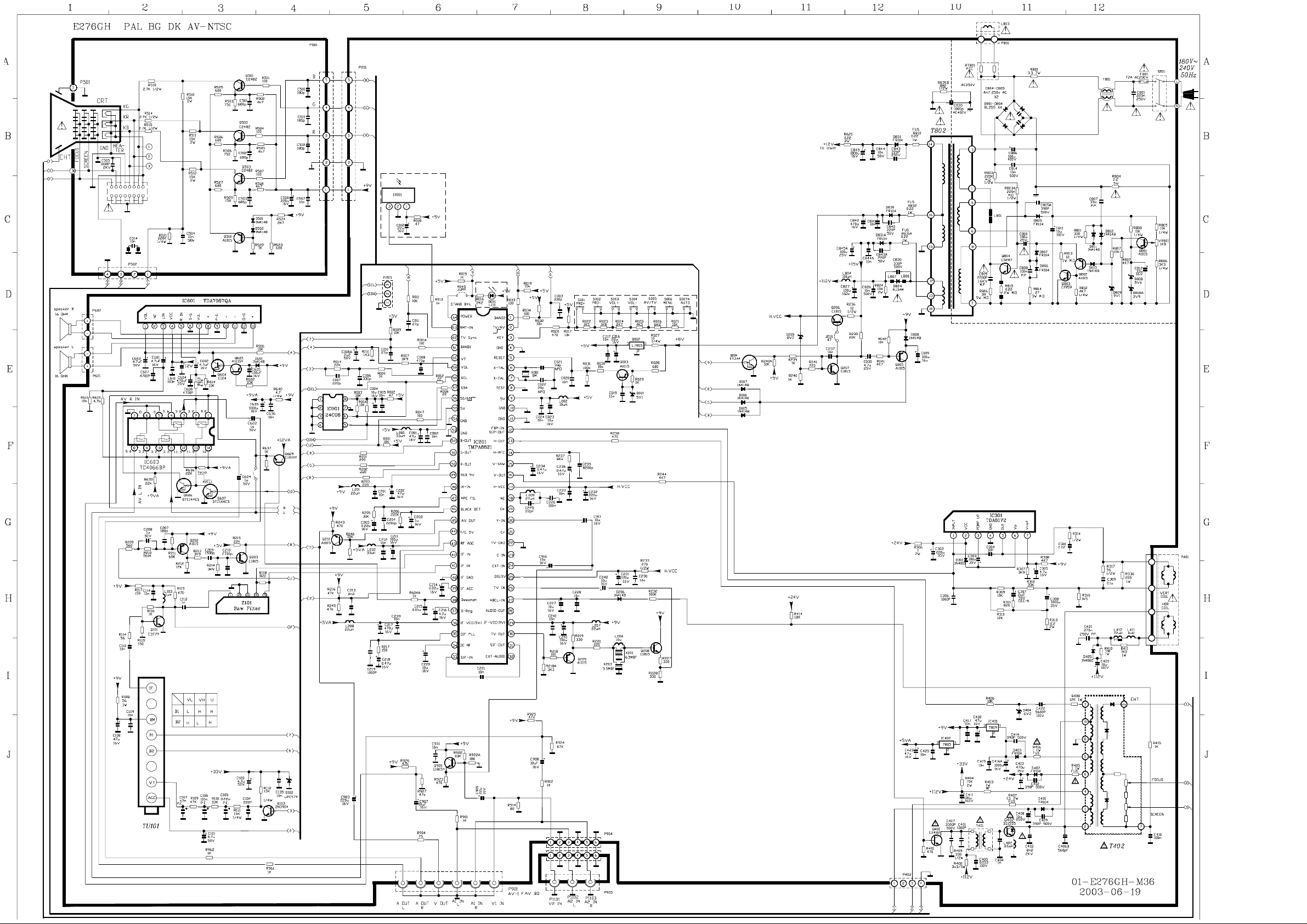
controller (MCU) and the other one is a signal processor (SP) for a color TV. The TV signal processor
contains PIF, SIF, Video, multi-standard chroma, Sync, RGB processors.
Page 4

РЧТТЧТЩ
НЗУЮСФРЧТЬЫНЭОЧРМЧСТНЗУЮСФРЧТЬЫНЭОЧРМЧСТ
BAND21Band selector SIF in 33
TV/AV2TV/AV switch DC NF 34
KEY3Panel key input PIF PLL 35
GND 4 GNDIFvcc(5V)36
RESET5System clock reset output S-reg37
X-TAL 6 Deepmph38
X’tal connecting pins
X-TAL 7
TEST 8
5V9Vdd Supply 5V IF in 41
GND10GND for Slicer circuit IF in 42
GND11GND terminal for Analog block.RF AGC 43
FBP in
/SCP out
H out 13
H-AFC 14
V saw 15
V out 16
H vcc 17
N.C.18N.C.Rout50
Cb19Input terminal for Cb signal. G out 51
Test pin for out-going test. Be tied to
low.
12Input terminal for FBP. Y/C 5V 44
Output terminal for Horizontal driving
pulse.
Terminal to be connectedcapacitor for
H AFC filter. This terminal voltage
controls H VCO frequency.
Terminalto be connected capacitor to
generate V saw signal. V saw
amplitude is kept constant by VAGC
function.
Output terminal for Vertical driving
pulse.
Vcc terminal for DEF circuit. Supply
9V. 9V.
IF AGC 39
IF GND 40GND terminal for IF circuit.
AV out 45
BLACK
DET
APC FIL 47
IK in 48
RGB 9V 49
Inputterminal for H correction and
2nd SIF.
Terminalto be connected capacitor
for DC Negative Feedback from SIF
Det output.
Terminal to beconnected withloop
filter for PIF PLL. This terminal
voltage is controlled PIF VCO
frequency.
Vcc terminal for IF circuit. Supply
5V.
Terminal to be
connectedcapacitor for stabilizing
internal bias.
Terminalto be connected capacitor
for SIF Det De-Emphasis.
Terminalto be connected with IF
AGC filter.
Input terminals for IF signals.Pin41
and Pin42 areboth input poles of
differential amplifier.
Output terminal for RF AGC control
level.
Vcc terminal for Y/C circuit. Supply
5V.
Output terminal for CVBS or Y signal
selected by BUS (Video SW).
Terminal to be connected with Black
46
Det filter for black stretch.
Terminal to beconnected withAPC
filter for Chroma demodulation. This
terminal voltagecontrols frequency of
VCXO
Input terminal to sense ACB cathode
current.
Vcc terminal for RGB circuit. Supply
Output terminals for R /G/B signal.
íï
Page 5

íî
Y in 20Input terminal for Y signal. B out 52
Cr 21 Input terminal for Cr signal. GND 53 GND terminal for Analog block.
TV-GND 22 GND terminal for Digital block. GND 54 scillator circuit GND for O
C in 23 Input terminal for Chroma signal. 5V 55 Vdd for Oscillator circuit Supply 5V
EXT in 24r Video signal. 50/60 Input terminal fo56PAL/NTSC selector
Vcc terminal for Digital block. This
DIG 5V 25
TV in 26 Input terminal for Video signal. SCL 58 I2C bus serial clock input /output
ABCL in 27 Input terminal for ABL/ACL control.VOL 59 trol signal output Volume con
Audioout terminal for Audio signal.28OutputVT60Tune voltage controller
IF vcc(9V) 29 Vcc terminal for IF circuit. Supply 9V.BAND1 61 selector Band
TV out 30
SIF out 31
EXT audio 32
terminal voltage is clipped about 3.3V
by regulator circuit.
Output terminal for detected PIF
signal.
Output terminal for detected SIF
signal.
Input terminal for E
signal.
xternal Audio
SDA 57 I2C bus serial data input /output
TV sync 62Sync signal input
RMT in 63
POWER 64
input
LED output
signal preprocessor Remote control
НЧЩТЯОСННСО ЬЫНЭОЧРМЧСТН
Ô ÐÝÛ
1. Tank-coil-less PIF VCO
PA8803 adopts a tank-coil-less PIF VCO circuith has nt
TM, whicadvaages of cost, performance of
IF inan layout. The PL systas
weak putd easy to design PCBIF PLem h
the micro controller needs only to order the PIF PLL system to start se the IIC
he seligc.
bus. Tlf-anment finishes within 50 mse
2. Built-in Soun
A sound
d Band Pass Filter
band pass filter is integrated on the chip for multi frequency SIF systems. The 1st SIF
demodulator multiplies PIF input signal and regenerated PIF carrier fro
self-alignment circuit, so that
lf-alignment through
m VCO with 90-degree angle,
and gets multi-frequency SIF signal as 6.5MHz, 6.0MHz, 5.5MHz and 4.5MHz according to the SIF
system. A frequez-SIF signal by
g thnv bus. The builsound BPF rejects undesired
frequency compol. A narrow-band 1 MHz PLL FM demodulator with no
external tank-coil achieves to output sound signal with better S/N ratio
ncy converter converts one of those four SIF signals into 1 MH
erting frequency through the IICselectine cot-in
nents of 1MHz-SIF signa
.
3. AFT
A recent IF systea digital AFT circuit. But analog DC voltage is used as interface between
an IF system andol loop. TMPA88
through IIC bus ss below.
m adopts
a micro controller in the AFT contr
hown a
03 adopts a digital interface
-stand Inals
4. NondarF sig
A8803 prepares ways for non-standard IF inputs. The OVEOD switch is available for
TMPR M
r-modulated PIF signals in the condition of more7.5%du
ove than 8 molation at 100 IRE, which is the
mum uld NTSC. ition, PA8803 has capability to
maximodation Standard of PAL anIn addTM
 Loading...