

Page 1

TCL
SERVICE MANUAL
1. Caution……………………………………………………………2
2. Specification………………………………………………………6
3. BOM List…………………………………………………………..9
4. Alignment Procedure………………………………………….…30
5. Block Diagram……………………………………………………39
6. Schematic Diagram………………………………………………40
7. PCB Layout………….……………………………………………41
8. Exploded View Diagram………………………..............................43
This manual is the latest at the time of printing, and does not
include the mo difi cat io n w hich may be made af ter the pri nti ng, by
the constant improvement of product.
AT2127
Page 2
WARNING: TO REDUCE RISK OF FIRE OR ELECTRIC SHOCK, DO NOT
EXPOSE THIS APPLIANCE TO RAIN OR MOISTURE.
CAUTION: TO REDUCE THE RISK OF
ELECTRICAL SHOCK, DO NOT REMOVE
COVER (OR BACK). NO USER SERVICEABLE
PARTS INSIDE. REFER SERVICING TO
QUALIFIED SERVICE PERSONNEL.
The lighting flash with arrowhead symbol, with an equilateral triangle is intended to
alert the user to the presence of uninsulated voltage within the products
enclosure that may be of sufficient magnitude to constitute a risk of electric shock to
the person.
The exclamation point within an equilateral triangle is intended to alert the user to the
presence of important operating and maintenance (servicing) instructions in the
literature accompanying the appliance.
CAUTION:
Use of controls, adjustments or procedures other than those specified herein may result in
hazardous radiation exposure.
CAUTION
RISK RISK OF OF ELECTRIELECTRICC
SHOCK SHOCK DO DO NOT NOT OPEN.OPEN.
2
dangerous
Page 3

3
FOR YOUR PERSONAL SAFETY
1. When the power cord or plug is damaged or frayed, unplug this television set from the wall outlet and refer servicing to
qualified service personnel.
2. Do not overload wall outlets and extension cords as this can result in fire or electric shock.
3. Do not allow anything to rest on or roll over the power cord, and do not place the TV where power cord is subject to
traffic or abuse. This may result in a shock or fire hazard.
4. Do not attempt to service this television set yourself as opening or removing covers may expose you to dangerous
voltage or other hazards. Refer all servicing to qualified service personnel.
5. Never push objects of any kind into this television set through cabinet slots as they may touch dangerous voltage
points or short out par ts that could result in a fire or electr ic shock. Never spill liquid of any kind on the television set.
6. If the television set has been dropped or the cabinet has been damaged, unplug this television set from the wall outlet
and refer servicing to qualified service personnel.
7. If liquid has been spilled into the television set, unplug this television set from the wall outlet and refer servicing to
qualified service personnel.
8. Do not subject your television set to impact of any kind. Be particularly careful not to damage the picture tube surface.
9. Unplug this television set from the wall outlet before cleaning. Do not use liquid cleaners or aerosol cleaners. Use a
damp cloth for cleaning.
10.1. Do not place this television set on an unstable cart, stand, or table. The television set may fall, causing serious injury
to a child or an adult, and serious damage to the appliance. Use only with a car t or stand recommended by the
manufacturer, or sold with the television set. Wall or shelf mounting should follow the manufacturer s instructions, and
should use a mounting kit approved by the manufacturer.
10.2. An appliance and car t combination should be moved with care. Quick stops, excessive force, and uneven surfaces
may cause the appliance and cart combination to overturn.
CAUTION:
Read all of these instructions. Save these instructions for later use. Follo w all Warnings and
Instructions marked on the audio equipment.
1. Read Instructions- All the safety and operating instructions should be read before the product is operated.
2. Retain Instructions- The safety and operating instructions should be retained for future reference.
3. Heed Warnings- All warnings on the product and in the operating instructions should be adhered to.
4. Follow Instructions- All operating and use instructions should be followed.
IMPORTANT SAFETY INSTRUCTIONS
Page 4
4
PROTECTION AND LOCATION OF YOUR SET
11. Do not use this television set near water ... for example, near a bathtub, washbowl, kitchen sink, or laundry tub, in a
wet basement, or near a swimming pool, etc.
Never expose the set to rain or water. If the set has been exposed to rain or water, unplug the set from the wall
outlet and refer servicing to qualified service personnel.
12. Choose a place where light (artificial or sunlight) does not shine directly on the screen.
13. Avoid dusty places, since piling up of dust inside TV chassis may cause failure of the set when high humidity persists.
14. The set has slots, or openings in the cabinet for ventilation purposes, to provide reliable operation of the receiver, to
protect it from overheating. These openings must not be blocked or covered.
Never cover the slots or openings with cloth or other material.
Never block the bottom ventilation slots of the set by placing it on a bed, sofa, rug, etc.
Never place the set near or over a radiator or heat register.
Never place the set in enclosure, unless proper ventilation is provided.
PROTECTION AND LOCATION OF YOUR SET
15.1. If an outside antenna is connected to the television set, be sure the antenna system is grounded so as to provide some
protection against voltage surges and built up static charges, Section 810 of the National Electrical Code, NFPA No.
70-1975, provides information with respect to proper grounding of the mast and supporting structure, grounding of the
lead-in wire to an antenna discharge unit, size of grounding conductors, location of antenna discharge unit, connection
to grounding electrode, and requirements for the grounding electrode.
15.2. Note to CATV system installer : (Only for the television set with CATV reception)
This reminder is provided to call the CATV system attention to Article 820-40 of the NEC that provides
guidelines for proper grounding and, in particular, specifies that the cable ground shall be connected to the grounding
system of the building, as close to the point of cable entry as practical.
16. An outside antenna system should not be located in the vicinity of overhead power lines or other electric lights or power
circuits, or where it can fall into such power lines or circuits. When installing an outside antenna system, extreme care
should be taken to keep from touching such power lines or circuits as contact with them might be fatal.
17. For added protection for this television set during a lightning storm, or when it is left unattended and unused for long
periods of time, unplug it from the wall outlet and disconnect the antenna. This will prevent damage due to lightning
and power-line surges.
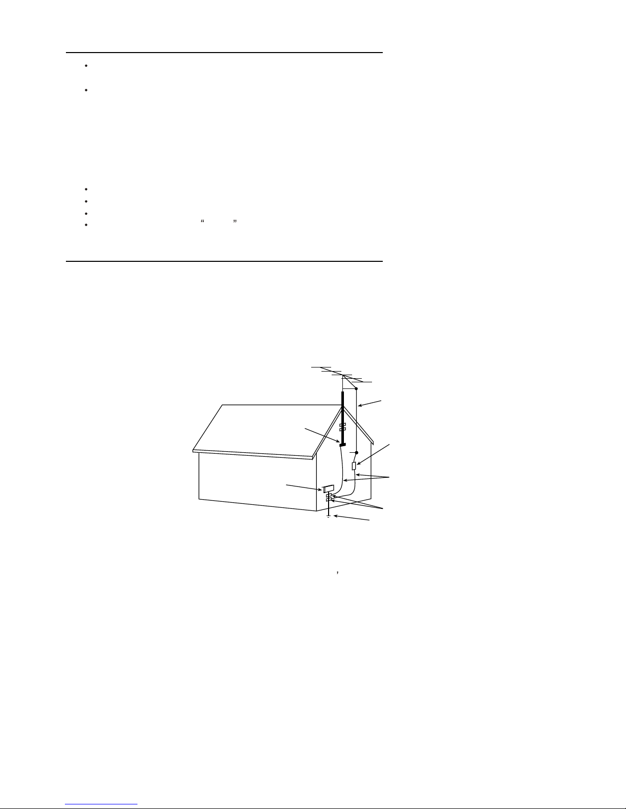
ANTENNA
LEAD- IN WIRE
ANTENNA DISCHARGE
UNIT (NEC SECTION
810-20)
GROUNDING
CONDUCTORS
(NEC SECTION810-21)
GROUND CLAMPS
POWER SERVICE GROUNDING
ELECTRODE SYSTEM
(NEC ART 250. PART H)
ELECTRIC SERVICE
EQUIPMENT
GROUND CLAMP
NEC-NATIONAL ELECTRICAL CODE
EXAMPLE OF ANTENNA GROUNDING AS PER
NATIONAL ELECTRICAL CODE
EXAMPLE OF ANTENNA GROUNDING AS PER NATIONAL ELECTRICAL CODE INSTRUCTIONS
a built-in
installer s
Page 5

OPERATION OF YOUR SET
18.
This television set should be operated only from the type of power source indicated on the marking label. If you are not
sure of the type of power supply at your home, consult your television dealer or local power company. For television
sets designed to operate from battery power, refer to the operating instructions.
19. If the television set does not operate normally by following the operating instructions, unplug this television set from the
wall outlet and refer servicing to qualified service personnel. Adjust only those controls that are covered in the operating
instructions as improper adjustment of other controls may result in damage and will often require extensive work by a
qualified technician to restore the television set to normal operation.
20. When going on a holiday : If your television set is to remain unused for a period of time, for instance, when you go on
a holiday, turn the television set and unplug the television set from the wall outlet.
IF THE SET DOES NOT OPERATE PROPERLY
21. If you are unable to restore normal operation by following the detailed procedure in your operating instructions,
do not attempt any further adjustment. Unplug the set and call your dealer or service technician.
22. Whenever the television set is damaged or fails, or a distinct change in performance indicates a need for
service, unplug the set and have it checked by a professional service technician.
23. It is normal for some TV sets to make occasional snapping or popping sounds, particularly when being
turned on or off. If the snapping or popping is continuous or frequent, unplug the set and consult your
dealer or service technician.
FOR SERVICE AND MODIFICATION
24. Do not use attachments not recommended by the television set manufacturer as they may cause hazards.
25. When replacement parts are required, be sure the service technician has used replacement parts specified
by the manufacturer that have the same characteristics as the original part. Unauthorized substitutions
may result in fire, electric shock, or other hazards.
26. Upon completion of any service or repairs to the television set, ask the service technician to perform
routine safety checks to determine that the television is in safe operating condition.
5
off
Page 6

PFS2 FORMAT-1 Report
Date:2004-11-16 15:19
ProductView......:
Report by............:
Specs / Products
MasterData
Customer Id
RADIO VICDTORIA
Version
1
Status
Locked
12NC
Brand
TCL
EAN
\
UPC
\
Rece
p
tion
+Tunin
g
- presets/channels
181, Full-Cable
+Tunin
g
- technolo
gy
PLL
+Tunin
g
- Indication
Full-Cable
+Fre
q
Bands
Freq
+Channels
+IF Fre
q
45.75M
+TV S
y
stems Off Air/Cable
NTSC-M, PAL MN
+Add S
y
stems Ext In
4.43 NTSC, 4.43PAL
+TV S
y
stems Multi
PAL NTSC
+Sound S
y
stems
AV STEREO
Picture - Processin
g
+Scan
Standard
+Scan Modes
4:03
+Wide Screen Switchin
g
+Combfilter
+Picture Control
Brightness, Color, Contrast, Tint, Sharpness
Con Var, Smart pict 4 modes
+Pict Enhancement
Blue Mute
+Pict Noise Reduction
Yes
Picture - Dis
play
+Display Type
+Screen Format
+Size
(
Visual)" - size/vis. cm
21"
+Deflection S
y
stem (CRT onl
y)
+Tube Technology (CRT onl
y)
+CRT Defl
+CRT Gun
+CRT Ma
g
n field
+Resolution
+Coatin
g (
only for D.V. sets
)
+White Point
Sound
+Leaflet Power
8W
+RMS Power Intern
2X4W(for 21")
+RMS Power Extern
+Surround Sound
' +Sound Features
Mute, Smart sound(4 modes)
+Sound Control
Balance, Bass, Treble, Volume
Sound - S
p
eakers
+S
p
eaker configuration
2 speakers
+S
p
eakers used
+S
p
eaker Size
User Interface
+Interface Name
2127
+Voice Control
+Menu
Cursor Control
+Menu Colours
+Menu Lan
guag
es
Spanish, English, Franch, Portuguese
+Special Features
V-chip with Child Lock, CCD, Favorite
channel, Notebook, Biological,Calendar
+O
p
erational Features
Alternate Channel/ recall
+PP Features
one PP for all channel
Product:
2127
2004-11-16 15:21 1465 PFS 1 of 3
Page 7
Date:2004-11-16 15:19
ProductView......:
Report by............:
Specs / Products
Product:
2127
+Tuning/Install Features
Auto Cable/ Auto select. Auto channel Prog,
Cable/Antenna select, Channnel Edit,
Factory Mode, Language Selection, Service
Mode
+Clock/Timer Functions
sleep timer
+Local Controls Front
Channel +/-, Volume+/-, Mains(Tact
Switch), Menu, TV/Video
+Local Controls To
p
+Indicators - screen
+Indicators - front
+Numb of Loc Cont
(
incl Mains
)
+Number of Ind. (incl Mains
)
+Local Controls (Old
)
Remote Control
+Remote Control - sco
p
e
TV
+Remote Control - t
yp
e
Standard
+Remote Control - t
yp
enr
F
+Remote Control - features
Connectors Rear
+Scart RGB+Y/C+CVBS
+Scart RGB+CVBS
+Scart CVBS+Y/C
+Com
p
onent In (Y/U/V) Cinch
+In Y/C+Cinch
(
CVBS+St
)
+In Y/C+Cinch(CVBS+Mo
)
+In Y/C+Cinch(St
)
+In BNC (CVBS
)
+In Cinch(CVBS+St
)
x
+In Cinch
(
CVBS+Mo
)
+Out Cinch(CVBS+St
)
x
+Out Cinch
(
CVBS+Mo
)
+Out Cinch Audio Stereo
+Out Cinch Audio Mono
+Out Cinch Dolb
y
Surround
+Di
g
Audio Out
+Louds
p
eakers
+Control Busses
+Feature Slot
+ITV Smart Port
+Terr. Antenna in
75 Ohms(F type)
Guide + IR Blaster Jack
Connectors Front
+In Cinch
(
CVBS + St
)
+In Cinch (CVBS+Mo
)
+Headphone Out
Connectors Side
+In Y/C + Cinch
(
CVBS+St
)
+In Y/C + Cinch Stereo
+In Cinch
(
CVBS + St
)
x
+IN Cinch
(
CVBS + Mo
)
+Headphone Out
Connectors To
p
Connectors Mechanical
St
y
lin
g
+Cabinet Name
2127
+Confi
g
uration
+Gra
p
hics/Logo's
TCL
+Cabinet Colour and Finish
+Mechanics
+S
p
eaker Visibilit
y
General
+Se
g
ment
+Chassis
M123A
+Software Deliver
y
Mode
+Software Version
+Mains Volta
g
e
110-240V
+Mains Fre
q
uenc
y
50Hz / 60 Hz
+T
yp
e Mains Cord
ARGENTINA
2004-11-16 15:21 1465 PFS 2 of 3
Page 8
Date:2004-11-16 15:19
ProductView......:
Report by............:
Specs / Products
Product:
2127
Power Consumption (P)TV in On
Power Consum
p
tion SB in Watts
less than 3W
Power Consum
p
tion Semi SB in W
+Power in "ON" for
+Power in Standb
y
for
+Power in "OFF" for
Wei
g
ht (P)TV (incl. Packagin
g)
Weight (P)TV (excl. Package
)
Weight AVUnit excl Packagin
g
+INDICATION on BACKCOVER
+Channel
Final E
quip
ment
+Packa
ging
- methods
+Documents and manuals
+Lan
guag
es DFU
+Cables Su
pp
lied
+Antenna Su
pp
lied
+Stand Su
pp
lied
+Aux E
quip
m Supplied
Packa
ging
- width cm
Packa
ging
- height cm
Packa
ging
- depth cm
Miscellaneous
+EAN Indication
+A
pp
robation
CB
+Tests
+Local Inte
g
ration
Various Perf. Param.
+Service Call-Rate
PIP/POP
+T
yp
e
+Features
Di
g
ital Reception
+Transmission
Built-in Data S
y
stem
+Text Standard
+
(
Tele)text Features
+Nbr bck
g
rnd page / Mem Size
+Text Technolo
gy
+Digital Data handlin
g
+Program Guide
Built-in Clock/Timer
+T
yp
e
+Features
Built-in Radio
+T
yp
e
Built-in PC dis
play
+PC Synch
+PC Control
Built-in DVD drive
+T
yp
e of Medium
+T
yp
e of Deck
Phased Out Items
+Tuner/Frontend
+Sensitivit
y
+CRT EHT
+Li
g
htning Protection
+Account
+XX
(
Radio Antenna in
)
+Non Volatile Memor
y
+In Y/C + Cinch(CVBS+Mo
)
Version of deck
2004-11-16 15:21 1465 PFS 3 of 3
Page 9

Item No. Description Quantity Req. Designator Remarks
08-002175-FRY ASS'Y - PACKING FOR F/R CAB. 1
74-100100-8CD POLYBAG (100CMX100CM) 2
74-344780-50C EPE BOARD (900mmx400mmx5mm) 0.75 FOR REAR CABINET
76-001497-0AF CARTON BOX LWH 640X460X360MM 0.0156 FOR OTHER PARTS
76-002111-0AR CARTON BOX LWH 765X605X480MM 0.25 FOR R.CAB.PACKING
76-002180-1AP CARTON BOX LWH 642X470X510MM 0.25 FOR F.CABINET
76-346740-01A CARTON SHEET LWH 440X620X3MM 0.0179 FOR OTHER PARTS
77-100100-6WC BUBBLE BAG (100cmX100cm) 0.5
74-360350-50C EPE BOARD (620mmX500mmX5mm) 0.5
74-279070-50C EPE BOARD (580mmX440mmX5mm) 0.25 FOR R.CAB
08-02127G-RCY ASS'Y - REAR CABINET 1
54-114000-00X FELT TAPE (150mmX19mmX0.3mm) 10 STICK ON REAR CAB.
55-356640-8CN REAR CABINET 1
58-2127MP-JKT PLATE MODEL NO. 1
58-347960-8UI INLAY REAR AV 1
59-130460-00X RUBBER PAD (25mmX7mm) 2 STICK ON R. CAB.(FOOTING)
62-314340-0UN FBT SUPPORTER HIPS-KINGFA 113 (VO) 1
62-345700-0UN ATTACHMENT RAIL PIPS-KINGFA 113 (VO) 1
63-B40250-AB2 S/T SCREW B 4 X 25 AB 4 MTG FRONT & REAR CAB.
63-F30100-BT3 S/T SCREW F 3 X 10 BT (BLACK) 2 MTG RCA JACK & RAER CAB.
63-W30100-AB4 S/T SCREW W 3 X 10 AB 2 MTG SUPPORTOR & REAR CAB
63-W30100-AB4 S/T SCREW W 3 X 10 AB 2 MTG M.BD TRACK & REAR CAB.
08-02175G-AVY 1
40-2175MU-SIC P.C.B. SIDE AV BD 1
46-35038H-05X HS 5P24 380 TJC3-5Y/SCN-5Y 1 P1104B P1 - P5 FOR M.BD P904
47-RCA020-XX1 RCA SOCKET Y/W/R 1 P1101
08-0A21SG-MAY 1
10-0FR104-FBX DIODE FR104 (FAST RECTIFIER) 1 D402
10-0FR104-FBX DIODE FR104 (FAST RECTIFIER) 1 D401
10-0FR104-FBX DIODE FR104 (FAST RECTIFIER) 1 D403
10-1N4001-EBX DIODE 1N4001 (RECTIFIER) 1 D301
10-1N4002-EBX DIODE 1N4002 (RECTIFIER) 1 D405
10-1N4148-ABX DIODE 1N4148 (SWITCHING) 1 D005
10-1N4148-ABX DIODE 1N4148 (SWITCHING) 1 D206
10-1N4148-ABX DIODE 1N4148 (SWITCHING) 1 D006
9
Page 10

Item No. Description Quantity Req. Designator Remarks
10-1N4148-ABX DIODE 1N4148 (SWITCHING) 1 D007
10-1N4148-ABX DIODE 1N4148 (SWITCHING) 1 D601
10-1N4148-ABX DIODE 1N4148 (SWITCHING) 1 D008
10-1N4148-ABX DIODE 1N4148 (SWITCHING) 1 D602
10-1N4148-ABX DIODE 1N4148 (SWITCHING) 1 D009
10-1N4148-ABX DIODE 1N4148 (SWITCHING) 1 D307
10-1N4148-ABX DIODE 1N4148 (SWITCHING) 1 D302
10-1N4148-ABX DIODE 1N4148 (SWITCHING) 1 D303
10-1N4148-ABX DIODE 1N4148 (SWITCHING) 1 D305
10-CW574C-DJX DIODE CW574CD 1 D101
10-79C3V9-DBX DIODE ZENER 3V9 1/2W 5% 1 D304
10-79C5V1-DBX DIODE ZENER 5V1 1/2W 5% 1 D001
11-A124ES-0BX TRANSISTOR PDTA124ES (PNP) 1 Q005
11-C124ES-0BX TRANSISTOR PDTC124ES (NPN) 1 Q604
11-C124ES-0BX TRANSISTOR PDTC124ES (NPN) 1 Q001
11-C124ES-0BX TRANSISTOR PDTC124ES (NPN) 1 Q004
11-C124ES-0BX TRANSISTOR PDTC124ES (NPN) 1 Q212
11-C144ES-0BX TRANSISTOR PDTC144ES (NPN) 1 Q211
11-DD1555-0AX TRANSISTOR 3DD1555 1 Q402
11-SA1015-YBX TRANSISTOR 2SA1015Y 1 Q003
11-SA1015-YBX TRANSISTOR 2SA1015Y 1 Q202
11-SA1015-YBX TRANSISTOR 2SA1015Y 1 Q605
11-SA1015-YBX TRANSISTOR 2SA1015Y 1 Q210
11-SC1815-YBX TRANSISTOR 2SC1815Y 1 Q203
11-SC1815-YBX TRANSISTOR 2SC1815Y 1 Q209
11-SC1815-YBX TRANSISTOR 2SC1815Y 1 Q002
11-SC1815-YBX TRANSISTOR 2SC1815Y 1 Q208
11-SC1815-YBX TRANSISTOR 2SC1815Y 1 Q905
11-SC2482-0BX TRANSISTOR 2SC2482 1 Q401
11-SC3779-DBX TRANSISTOR 2SC3779D (RF AMPL) 1 Q101
13-00M24C-08P IC EEPROM 8K M24C08 (WRITE) 1 IC001
13-0STV93-02S IC STV9302 1 IC301
13-L7809C-VAP IC L7809CV 1 IC401
13-TDA705-7AS IC TDA7057AQ (R/L AUDIO O/P) 1 IC601
18-CB0100-JNX RES. C.F. 10 OHM 1/6W +/-5% 1 J217
10
Page 11

Item No. Description Quantity Req. Designator Remarks
18-CB0101-JNX RES. C.F. 100 OHM 1/6W +/-5% 1 R218
18-CB0101-JNX RES. C.F. 100 OHM 1/6W +/-5% 1 R009
18-CB0101-JNX RES. C.F. 100 OHM 1/6W +/-5% 1 R228
18-CB0102-JNX RES. C.F. 1K OHM 1/6W +/-5% 1 R415
18-CB0102-JNX RES. C.F. 1K OHM 1/6W +/-5% 1 R013
18-CB0102-JNX RES. C.F. 1K OHM 1/6W +/-5% 1 R234
18-CB0102-JNX RES. C.F. 1K OHM 1/6W +/-5% 1 R029
18-CB0102-JNX RES. C.F. 1K OHM 1/6W +/-5% 1 R116
18-CB0102-JNX RES. C.F. 1K OHM 1/6W +/-5% 1 R051
18-CB0102-JNX RES. C.F. 1K OHM 1/6W +/-5% 1 R901
18-CB0102-JNX RES. C.F. 1K OHM 1/6W +/-5% 1 R922
18-CB0102-JNX RES. C.F. 1K OHM 1/6W +/-5% 1 R902
18-CB0102-JNX RES. C.F. 1K OHM 1/6W +/-5% 1 R920
18-CB0103-JNX RES. C.F. 10K OHM 1/6W +/-5% 1 R012
18-CB0103-JNX RES. C.F. 10K OHM 1/6W +/-5% 1 R011
18-CB0103-JNX RES. C.F. 10K OHM 1/6W +/-5% 1 R030
18-CB0103-JNX RES. C.F. 10K OHM 1/6W +/-5% 1 R050
18-CB0103-JNX RES. C.F. 10K OHM 1/6W +/-5% 1 R043
18-CB0103-JNX RES. C.F. 10K OHM 1/6W +/-5% 1 R042
18-CB0103-JNX RES. C.F. 10K OHM 1/6W +/-5% 1 R006
18-CB0102-JNX RES. C.F. 1K OHM 1/6W +/-5% 1 R924
18-CB0103-JNX RES. C.F. 10K OHM 1/6W +/-5% 1 R047
18-CB0103-JNX RES. C.F. 10K OHM 1/6W +/-5% 1 R052
18-CB0104-JNX RES. C.F. 100K OHM 1/6W +/-5% 1 R031
18-CB0121-JNX RES. C.F. 120 OHM 1/6W +/-5% 1 R227
18-CB0123-JNX RES. C.F. 12k OHM 1/6W +/-5% 1 R212
18-CB0151-JNX RES. C.F. 150 OHM 1/6W +/-5% 1 R115
18-CB0151-JNX RES. C.F. 150 OHM 1/6W +/-5% 1 R117
18-CB0122-JNX RES. C.F. 1.2k OHM 1/6W +/-5% 1 R007
18-CB0153-JNX RES. C.F. 15k OHM 1/6W +/-5% 1 R315
18-CB0221-JNX RES. C.F. 220 OHM 1/6W +/-5% 1 R201
18-CB0221-JNX RES. C.F. 220 OHM 1/6W +/-5% 1 R202
18-CB0221-JNX RES. C.F. 220 OHM 1/6W +/-5% 1 R203
18-CB0221-JNX RES. C.F. 220 OHM 1/6W +/-5% 1 R220
18-CB0221-JNX RES. C.F. 220 OHM 1/6W +/-5% 1 R238
11
Page 12

Item No. Description Quantity Req. Designator Remarks
18-CB0221-JNX RES. C.F. 220 OHM 1/6W +/-5% 1 R401
18-CB0222-JNX RES. C.F. 2.2k OHM 1/6W +/-5% 1 R055
18-CB0222-JNX RES. C.F. 2.2k OHM 1/6W +/-5% 1 R044
18-CB0223-JNX RES. C.F. 22k OHM 1/6W +/-5% 1 R215
18-CB0223-JNX RES. C.F. 22k OHM 1/6W +/-5% 1 R912
18-CB0223-JNX RES. C.F. 22k OHM 1/6W +/-5% 1 R913
18-CB0224-JNX RES. C.F. 220k OHM 1/6W +/-5% 1 R206
18-CB0271-JNX RES. C.F. 270 OHM 1/6W +/-5% 1 R217
18-CB0271-JNX RES. C.F. 270 OHM 1/6W +/-5% 1 R233
18-CB0303-JNX RES. C.F. 30K OHM 1/6W +/-5% 1 R205
18-CB0331-JNX RES. C.F. 330 OHM 1/6W +/-5% 1 R219
18-CB0332-JNX RES. C.F. 3.3k OHM 1/6W +/-5% 1 R218A
18-CB0332-JNX RES. C.F. 3.3k OHM 1/6W +/-5% 1 R046
18-CB0333-JNX RES. C.F. 33K OHM 1/6W +/-5% 1 R602
18-CB0334-JNX RES. C.F. 330K OHM 1/6W +/-5% 1 R232
18-CB0392-JNX RES. C.F. 3.9K OHM 1/6W +/-5% 1 R213
18-CB0392-JNX RES. C.F. 3.9K OHM 1/6W +/-5% 1 R214
18-CB0470-JNX RES. C.F. 47 OHM 1/6W +/-5% 1 R002
18-CB0471-JNX RES. C.F. 470 OHM 1/6W +/-5% 1 R119
18-CB0471-JNX RES. C.F. 470 OHM 1/6W +/-5% 1 R208
18-CB0472-JNX RES. C.F. 4.7k OHM 1/6W +/-5% 1 R015
18-CB0472-JNX RES. C.F. 4.7k OHM 1/6W +/-5% 1 R311
18-CB0473-JNX RES. C.F. 47K OHM 1/6W +/-5% 1 R216
18-CB0473-JNX RES. C.F. 47K OHM 1/6W +/-5% 1 R245
18-CB0560-JNX RES. C.F. 56 OHM 1/6W +/-5% 1 R114
18-CB0561-JNX RES. C.F. 560 OHM 1/6W +/-5% 1 R209
18-CB0564-JNX RES. C.F. 560K OHM 1/6W +/-5% 1 R210
18-CB0681-JNX RES. C.F. 680 OHM 1/6W +/-5% 1 R028
18-CB0683-JNX RES. C.F. 68K OHM 1/6W +/-5% 1 R211
18-CB0751-JNX RES. C.F. 750 OHM 1/6W +/-5% 1 R008
18-CB0820-JNX RES. C.F. 82 OHM 1/6W +/-5% 1 R903
18-CB0820-JNX RES. C.F. 82 OHM 1/6W +/-5% 1 R923
18-CB0821-JNX RES. C.F. 820 OHM 1/6W +/-5% 1 R118
18-CB0822-JNX RES. C.F. 8.2K OHM 1/6W +/-5% 1 R237
18-CB0822-JNX RES. C.F. 8.2K OHM 1/6W +/-5% 1 R606
12
Page 13

Item No. Description Quantity Req. Designator Remarks
18-CD0100-JNX RES. C.F. 10 OHM 1/4W +/-5% 1 R027
18-DB0103-FNX RES. M.F. 10K OHM 1/6W +/-1% 1 R302
18-DB0104-FNX RES. M.F. 100K OHM 1/6W +/-1% 1 R303
18-DB0153-FNX RES. M.F. 15K OHM 1/6W +/-1% 1 R244
18-DB0223-FNX RES. M.F. 22K OHM 1/6W +/-1% 1 R306
18-EF0109-JGX RES. FUS. 1 OHM 1W +/-5% (LS) 1 R403
18-EF0109-JGX RES. FUS. 1 OHM 1W +/-5% (LS) 1 R405
18-EF0109-JGX RES. FUS. 1 OHM 1W +/-5% (LS) 1 R418
18-EF0109-JGX RES. FUS. 1 OHM 1W +/-5% (LS) 1 R409
18-FF0103-JGX RES. M.O. 10k OHM 1W +/-5% 1 R410
18-FF0129-JGX RES. M.O. 1.2 OHM 1W +/-5% 1 R304
18-FF0221-JGX RES. M.O. 220 OHM 1W +/-5% 1 R336
18-FG0153-JHX RES. M.O. 15k OHM 2W +/-5% 1 R404
18-GJ0332-JUX1 RES.C.C.5W 3.3KOHM +/-5% 1 R402
18-RG0228-JHX RES. WIRE ROUND 0.22 OHM 2W +/-5% 1 R620
25-BCA102-M1X CAP. ELEC 1000 UF 16V +/-20% 1 C232
25-BCB100-M1X CAP. ELEC 10 UF 16V +/-20% 1 C004
25-BCB100-M1X CAP. ELEC 10 UF 16V +/-20% 1 C220
25-BCB100-M1X CAP. ELEC 10 UF 16V +/-20% 1 C023
25-BCB100-M1X CAP. ELEC 10 UF 16V +/-20% 1 C227
25-BCB100-M1X CAP. ELEC 10 UF 16V +/-20% 1 C231
25-BCB100-M1X CAP. ELEC 10 UF 16V +/-20% 1 C603
25-BCB100-M1X CAP. ELEC 10 UF 16V +/-20% 1 C901
25-BCB100-M1X CAP. ELEC 10 UF 16V +/-20% 1 C902
25-BCB100-M1X CAP. ELEC 10 UF 16V +/-20% 1 C907
25-BCB100-M1X CAP. ELEC 10 UF 16V +/-20% 1 C025
25-BCB100-M1X CAP. ELEC 10 UF 16V +/-20% 1 C311
25-BCB101-M1X CAP. ELEC 100 UF 16V +/-20% 1 C240
25-BCB101-M1X CAP. ELEC 100 UF 16V +/-20% 1 C605
25-BCB101-M1X CAP. ELEC 100 UF 16V +/-20% 1 C211
25-BCB101-M1X CAP. ELEC 100 UF 16V +/-20% 1 C101
25-BCB101-M1X CAP. ELEC 100 UF 16V +/-20% 1 C016
25-BCB101-M1X CAP. ELEC 100 UF 16V +/-20% 1 C903
25-BCB221-M1X CAP. ELEC 220 UF 16V +/-20% 1 C418
25-BCB221-M1X CAP. ELEC 220 UF 16V +/-20% 1 C906
13
Page 14

Item No. Description Quantity Req. Designator Remarks
25-BCB470-M1X CAP. ELEC 47 UF 16V +/-20% 1 C423
25-BCB470-M1X CAP. ELEC 47 UF 16V +/-20% 1 C202
25-BCB470-M1X CAP. ELEC 47 UF 16V +/-20% 1 C082
25-BDA471-M1X CAP. ELEC 470 UF 25V +/-20% 1 C217
25-BDA471-M1X CAP. ELEC 470 UF 25V +/-20% 1 C604
25-BDA471-M1X CAP. ELEC 470 UF 25V +/-20% 1 C415
25-BDB221-M1X CAP. ELEC 220 UF 25V +/-20% 1 C301
25-BEA102-M1X CAP. ELEC 1000 UF 35V +/-20% 1 C413
25-BEB101-M1X CAP. ELEC 100 UF 35V +/-20% 1 C302
25-BFB109-M1X CAP. ELEC 1 UF 50V +/-20% 1 C208
25-BFB109-M1X CAP. ELEC 1 UF 50V +/-20% 1 C915
25-BFB109-M1X CAP. ELEC 1 UF 50V +/-20% 1 C916
25-BFB109-M1X CAP. ELEC 1 UF 50V +/-20% 1 C203
25-BFB109-M1X CAP. ELEC 1 UF 50V +/-20% 1 C008A
25-BFB109-M1X CAP. ELEC 1 UF 50V +/-20% 1 C214
25-BFB220-M1X CAP. ELEC 22 UF 50V +/-20% 1 C106
25-BFB478-M1X CAP. ELEC 0.47 UF 50V +/-20% 1 C218
25-BFB479-M1X CAP. ELEC 4.7 UF 50V +/-20% 1 C304
25-BFB479-M1X CAP. ELEC 4.7 UF 50V +/-20% 1 C216
25-BFB479-M1X CAP. ELEC 4.7 UF 50V +/-20% 1 C104
25-BFB479-M1X CAP. ELEC 4.7 UF 50V +/-20% 1 C310
25-BHB100-M1X CAP. ELEC 10 UF 100V +/-20% 1 C420
25-BJA470-M1X CAP. ELEC 47 UF 160V +/-20% 1 C411
25-BLA100-M1X CAP. ELEC 10 UF 250V +/-20% 1 C408
25-GFB228-K1X CAP. ELEC 0.22 UF 50V +/-10% 1 C205
25-GFB478-K1X CAP. ELEC 0.47 UF 50V +/-10% 1 C234
25-GFB478-K1X CAP. ELEC 0.47 UF 50V +/-10% 1 C236
26-AIC102-KBX CAP. CER 1000 PF 500V +/-10% B 1 C401
26-AIC102-KBX CAP. CER 1000 PF 500V +/-10% B 1 C404
26-AIC391-KBX CAP. CER 390 PF 500V +/-10% B 1 C409
26-EBP102-KBX CAP. CER 1000 PF 50V +/-10% B 1 C112
26-EBP102-KBX CAP. CER 1000 PF 50V +/-10% B 1 C219
26-EBP103-ZFX CAP. CER 0.01UF 50V +80/-20% F 1 C212
26-EBP103-ZFX CAP. CER 0.01UF 50V +80/-20% F 1 C102
26-EBP103-ZFX CAP. CER 0.01UF 50V +80/-20% F 1 C019
14
Page 15

Item No. Description Quantity Req. Designator Remarks
26-EBP103-ZFX CAP. CER 0.01UF 50V +80/-20% F 1 C114
26-EBP103-ZFX CAP. CER 0.01UF 50V +80/-20% F 1 C024
26-EBP103-ZFX CAP. CER 0.01UF 50V +80/-20% F 1 C201
26-EBP103-ZFX CAP. CER 0.01UF 50V +80/-20% F 1 C241
26-EBP103-ZFX CAP. CER 0.01UF 50V +80/-20% F 1 C005
26-EBP103-ZFX CAP. CER 0.01UF 50V +80/-20% F 1 C228
26-EBP103-ZFX CAP. CER 0.01UF 50V +80/-20% F 1 C230
26-EBP103-ZFX CAP. CER 0.01UF 50V +80/-20% F 1 C233
26-EBP103-ZFX CAP. CER 0.01UF 50V +80/-20% F 1 C425
26-EBP103-ZFX CAP. CER 0.01UF 50V +80/-20% F 1 C417
26-EBP103-ZFX CAP. CER 0.01UF 50V +80/-20% F 1 C110
26-EBP103-ZFX CAP. CER 0.01UF 50V +80/-20% F 1 C239
26-EBP103-ZFX CAP. CER 0.01UF 50V +80/-20% F 1 C020
26-EBP103-ZFX CAP. CER 0.01UF 50V +80/-20% F 1 C017
26-EBP103-ZFX CAP. CER 0.01UF 50V +80/-20% F 1 C221
26-EBP103-ZFX CAP. CER 0.01UF 50V +80/-20% F 1 C081
26-EBP103-ZFX CAP. CER 0.01UF 50V +80/-20% F 1 C105
26-EBP152-KBX CAP. CER 1500pF 50V +/-10% B 1 C209
26-EBP181-JCX CAP. CER 180PF 50V +/-5% CH 1 C207
26-EBP270-JCX CAP. CER 27PF 50V +/-5% CH 1 C011
26-EBP272-KBX CAP. CER 2700pF 50V +/-10% B 1 C210
26-EBP331-JCX CAP. CER 330PF 50V +/-5% CH 1 C018
26-EBP391-JCX CAP. CER. 390PF 50V +/-5% CH 1 C403
26-EBP391-JCX CAP. CER. 390PF 50V +/-5% CH 1 C412
27-AGQ563-J0X CAP. M.PP 0.056 UF 250V +/-5% 1 C410
27-MBC104-J0X CAP. M.P.E 0.1 UF 63V +/-5% 1 C909
27-MBC104-J0X CAP. M.P.E 0.1 UF 63V +/-5% 1 C610
27-MBC104-J0X CAP. M.P.E 0.1 UF 63V +/-5% 1 C309
27-MBC104-J0X CAP. M.P.E 0.1 UF 63V +/-5% 1 C242
27-MBC224-J0X CAP. M.P.E 0.22UF 63V +/-5% 1 C305
27-MBC474-J0X CAP. M.P.E 0.47UF 63V +/-5% 1 C601
27-MBC474-J0X CAP. M.P.E 0.47UF 63V +/-5% 1 C602
27-PBC222-J0X CAP. P.E 0.0022UF 63V +/-5% 1 C213
27-PBC222-J0X CAP. P.E 0.0022UF 63V +/-5% 1 C204
27-PBC822-J0X CAP. P.E 0.0082UF 63V +/-5% 1 C235
15
Page 16

Item No. Description Quantity Req. Designator Remarks
34-A109K0-1IX COIL CHOKE 1 UH +/-10% 1 L103
34-A109K0-1IX COIL CHOKE 1 UH +/-10% 1 L102
34-R100J2-0EX COIL PL - 10 UH +/-5% 1 L002
34-R220J2-0EX COIL PL - 22 UH +/-5% 1 L208
34-R220J2-0EX COIL PL - 22 UH +/-5% 1 L207
34-R330J2-0EX COIL PL - 33 UH +/-5% 1 L080
34-R330J2-0EX COIL PL - 33 UH +/-5% 1 L202
34-R829J2-0EX COIL PL - 8.2 UH +/-5% 1 L204
36-HDR001-AX1 TRANSFOR HOR. DRIVE (MAGNETIC CORE) 1 T401
41-WJ0050-B00 WIRE BARE JUMPER 5MM 1 L101
41-WJ0060-B00 WIRE BARE JUMPER 6mm 1 J009A
41-WJ0060-B00 WIRE BARE JUMPER 6mm 1 J015
41-WJ0060-B00 WIRE BARE JUMPER 6mm 1 J101
41-WJ0060-B00 WIRE BARE JUMPER 6mm 1 J203
41-WJ0060-B00 WIRE BARE JUMPER 6mm 1 J210
41-WJ0060-B00 WIRE BARE JUMPER 6mm 1 J211
41-WJ0060-B00 WIRE BARE JUMPER 6mm 1 R204
41-WJ0060-B00 WIRE BARE JUMPER 6mm 1 R207
41-WJ0060-B00 WIRE BARE JUMPER 6mm 1 R249
41-WJ0060-B00 WIRE BARE JUMPER 6mm 1 J001
41-WJ0060-B00 WIRE BARE JUMPER 6mm 1 R200
41-WJ0060-B00 WIRE BARE JUMPER 6mm 1 J907
41-WJ0065-B00 WIRE BARE JUMPER 6.5MM 1 J010
41-WJ0065-B00 WIRE BARE JUMPER 6.5MM 1 J208
41-WJ0065-B00 WIRE BARE JUMPER 6.5MM 1 J301
41-WJ0070-B00 WIRE BARE JUMPER 7MM 1 J217A
41-WJ0070-B00 WIRE BARE JUMPER 7MM 1 J011
41-WJ0070-B00 WIRE BARE JUMPER 7MM 1 J012
41-WJ0075-B00 WIRE BARE JUMPER 7.5MM 1 J018
41-WJ0075-B00 WIRE BARE JUMPER 7.5MM 1 J218
41-WJ0075-B00 WIRE BARE JUMPER 7.5MM 1 J215
41-WJ0075-B00 WIRE BARE JUMPER 7.5MM 1 J602
41-WJ0075-B00 WIRE BARE JUMPER 7.5MM 1 J303
41-WJ0075-B00 WIRE BARE JUMPER 7.5MM 1 J022
41-WJ0075-B00 WIRE BARE JUMPER 7.5MM 1 J913
16
Page 17

Item No. Description Quantity Req. Designator Remarks
41-WJ0075-B00 WIRE BARE JUMPER 7.5MM 1 J225
41-WJ0075-B00 WIRE BARE JUMPER 7.5MM 1 J914
41-WJ0075-B00 WIRE BARE JUMPER 7.5MM 1 J901
41-WJ0080-B00 WIRE BARE JUMPER 8 MM 1 J108
41-WJ0080-B00 WIRE BARE JUMPER 8 MM 1 J903
41-WJ0080-B00 WIRE BARE JUMPER 8 MM 1 J919
41-WJ0085-B00 WIRE BARE JUMPER 8.5MM 1 J219
41-WJ0085-B00 WIRE BARE JUMPER 8.5MM 1 J209
41-WJ0085-B00 WIRE BARE JUMPER 8.5MM 1 J302
41-WJ0085-B00 WIRE BARE JUMPER 8.5MM 1 J306
41-WJ0085-B00 WIRE BARE JUMPER 8.5MM 1 J920
41-WJ0090-B00 WIRE BARE JUMPER 9MM 1 J212
41-WJ0090-B00 WIRE BARE JUMPER 9MM 1 J904
41-WJ0095-B00 WIRE BARE JUMPER 9.5MM 1 J230
41-WJ0095-B00 WIRE BARE JUMPER 9.5MM 1 J601
41-WJ0095-B00 WIRE BARE JUMPER 9.5MM 1 J231
41-WJ0095-B00 WIRE BARE JUMPER 9.5MM 1 J229
41-WJ0100-B00 WIRE BARE JUMPER 10MM 1 J102
41-WJ0100-B00 WIRE BARE JUMPER 10MM 1 J221
41-WJ0100-B00 WIRE BARE JUMPER 10MM 1 J002
41-WJ0100-B00 WIRE BARE JUMPER 10MM 1 J002A
41-WJ0100-B00 WIRE BARE JUMPER 10MM 1 J003
41-WJ0100-B00 WIRE BARE JUMPER 10MM 1 J402
41-WJ0100-B00 WIRE BARE JUMPER 10MM 1 J110
41-WJ0100-B00 WIRE BARE JUMPER 10MM 1 J917
41-WJ0100-B00 WIRE BARE JUMPER 10MM 1 J111
41-WJ0100-B00 WIRE BARE JUMPER 10MM 1 J017
41-WJ0100-B00 WIRE BARE JUMPER 10MM 1 J910
41-WJ0100-B00 WIRE BARE JUMPER 10MM 1 J911
41-WJ0105-B00 WIRE BARE JUMPER 10.5MM 1 J304
41-WJ0110-B00 WIRE BARE JUMPER 11MM 1 J016
41-WJ0110-B00 WIRE BARE JUMPER 11MM 1 J226
41-WJ0115-B00 WIRE BARE JUMPER 11.5MM 1 J604
41-WJ0125-B00 WIRE BARE JUMPER 12.5MM 1 J106
41-WJ0125-B00 WIRE BARE JUMPER 12.5MM 1 R317
17
Page 18

Item No. Description Quantity Req. Designator Remarks
41-WJ0125-B00 WIRE BARE JUMPER 12.5MM 1 J216
41-WJ0130-B00 WIRE BARE JUMPER 13MM 1 J204
41-WJ0130-B00 WIRE BARE JUMPER 13MM 1 J006
41-WJ0135-B00 WIRE BARE JUMPER 13.5MM 1 J014
41-WJ0140-B00 WIRE BARE JUMPER 14MM 1 J005
41-WJ0160-B00 WIRE BARE JUMPER 16MM 1 J105
41-WJ0165-B00 WIRE BARE JUMPER 16.5MM 1 J220
41-WJ0165-B00 WIRE BARE JUMPER 16.5MM 1 J013
41-WJ0170-B00 WIRE BARE JUMPER 17MM 1 J401
41-WJ0175-B00 WIRE BARE JUMPER 17.5MM 1 R045
41-WJ0195-B00 WIRE BARE JUMPER 19.5MM 1 J003A
41-WJ0200-B00 WIRE BARE JUMPER 20MM 1 J233
45-OSC8M0-0Y0 CRYSTAL 8.0MHZ 1 X001
45-TRA4M5-0Y0 CER TRAP TPS 4.5MHZ 1 X201
46-12866W-02X PIN BASE *2 S11-02Y 1 P601 FOR FRONT CAB.(SPK)
46-20598W-04X PIN BASE *4 TJC1-4A 1 P401 FOR DY CONNECTER
46-33079W-02X PIN BASE *2 TJC3-2A 1 P602 FOR FRONT CAB.(SPK)
46-33079W-05X PIN BASE *5 TJC3-5A 1 P201 FOR CRT BD P503
46-35179W-04X PIN BASE TJC3-4A 1 P402 FOR CRT BD P502
57-10654X-00F cable ties(2.5mmX95mm) 3
64-P30060-104 M/C SCREW 3 X 6 (ZINC) 2 FOR IC401 & IC402
64-P30100-104 M/C SCREW P 3 X 10 2 FOR IC601
64-P30100-104 M/C SCREW P 3 X 10 2 FOR Q402 & IC301
65-Z30050-23M NUT M 3 2 FOR Q402 & IC301
66-343730-0B0 HOLLOW RIVET 1.6X3.0XL3.2 2 FOR L411
66-343730-0B0 HOLLOW RIVET 1.6X3.0XL3.2 3 FOR Q402
66-343730-0B0 HOLLOW RIVET 1.6X3.0XL3.2 9 FOR T402
66-343730-0B0 HOLLOW RIVET 1.6X3.0XL3.2 2 FOR L412
66-343730-0B0 HOLLOW RIVET 1.6X3.0XL3.2 4 FOR C421,C406B
67-H24249-2M2 HEAT SINK 1 FOR IC402
67-H24249-3M2 HEAT SINK 1 FOR IC401
67-H30752-3A0 HEAT SINK 2 FOR IC301 & Q402
67-H34423-EA0 HEAT SINK 1 FOR IC601
18-CD0101-JNX RES. C.F. 100 OHM 1/4W +/-5% 1 R621
62-227680-0UA BRACKET ABS-KINGFA 606 (UO) 1
18
Page 19

Item No. Description Quantity Req. Designator Remarks
27-RCP333-J0X CAP. PP 0.033 UF 100V +/-5% 1 C405
13-L7805C-VAP IC L7805CV 1.5A (REGULATOR) 1 IC402
27-MBC103-J0X CAP. M.P.E 0.01UF 63V+/-5% 1 C215
27-PBC472-J0X CAP. P.E 0.0047UF 63V +/-5% 1 C607
27-PBC472-J0X CAP. P.E 0.0047UF 63V +/-5% 1 C608
18-CB0220-JNX RES. C.F. 22 OHM 1/6W +/-5% 1 R001
18-CB0220-JNX RES. C.F. 22 OHM 1/6W +/-5% 1 R005
18-CB0472-JNX RES. C.F. 4.7k OHM 1/6W +/-5% 1 R003
18-CB0472-JNX RES. C.F. 4.7k OHM 1/6W +/-5% 1 R004
34-A220K0-1IX COIL PL - 22UH +/-10% LGA0305-220K 1 L201
66-343740-0B0 HOLLOW RIVET (2.3mmx4.0mmx3.5mm) 2 FOR R402
41-WJ0055-B00 WIRE BARE JUMPER 5.5 MM 1 J922
46-33079W-03X PIN BASE *3 TJC3-3A 1 P001
18-FF0102-JGX RES. M.O. 1k OHM 1W +/-5% 1 R408
27-PBC472-J0X CAP. P.E 0.0047UF 63V +/-5% 1 C422
10-0FR104-FBX DIODE FR104 (FAST RECTIFIER) 1 D404
18-FF0123-JGX RES. M.O. 12k OHM 1W +/-5% 1 R406
18-CB0103-JNX RES. C.F. 10K OHM 1/6W +/-5% 1 J305
40-2111SG-MAI1X P.C.B. MAIN PCB BD 1
41-WJ0105-B00 WIRE BARE JUMPER 10.5MM 1 R406A
41-WJ0085-B00 WIRE BARE JUMPER 8.5MM 1 J205
41-WJ0085-B00 WIRE BARE JUMPER 8.5MM 1 J206
25-BCB101-M1X CAP. ELEC 100 UF 16V +/-20% 1 C900
10-79C8V2-DBX DIODE ZENER 8V2 1/2W 5% 1 D406
26-EBP470-JZX CAP. CER 47PF 50V +/-5% SL 1 C424
26-EBP222-KBX CAP. CER 2200PF 50V +/-10% B 1 C014
41-WJ0150-B00 WIRE BARE JUMPER 15MM 1 L402
41-WJ0070-B00 WIRE BARE JUMPER 7MM 1 J223
26-EBP101-JZX CAP. CER 100pF 50V +/-5% SL 1 C001
26-EBP101-JZX CAP. CER 100pF 50V +/-5% SL 1 C002
26-EBP390-JZX CAP. CER 39 pF 50V +/-5% 1 C021
26-EBP390-JZX CAP. CER 39 pF 50V +/-5% 1 C022
08-0A21SG-PWY 1
10-0FR104-FBX DIODE FR104 (FAST RECTIFIER) 1 D833
10-0FR104-FBX DIODE FR104 (FAST RECTIFIER) 1 D802
19
Page 20

Item No. Description Quantity Req. Designator Remarks
10-0RL255-EBX DIODE RL255 (POWER RECTIFIER) 1 D815
10-0RL255-EBX DIODE RL255 (POWER RECTIFIER) 1 D816
10-0RL255-EBX DIODE RL255 (POWER RECTIFIER) 1 D817
10-0RL255-EBX DIODE RL255 (POWER RECTIFIER) 1 D818
10-0RU3YX-F0X DIODE RU3YX (FAST RECTIFIER) 1 D830
10-1N4148-ABX DIODE 1N4148 (SWITCHING) 1 D805
10-1SS136-ABX DIODE 1SS136 1 D804
10-1SS136-ABX DIODE 1SS136 1 D835
10-79C8V2-DBX DIODE ZENER 8V2 1/2W 5% 1 D839
10-HER108-FBX DIODE HER108 1 D806
10-HS16VC-DBX DIODE 500mW 16HSC 1 D838
10-HS6V2B-DBX DIODE 6V2 500mW 1 D840
11-SC1815-YBX TRANSISTOR 2SC1815Y 1 Q832
11-SC1815-YBX TRANSISTOR 2SC1815Y 1 Q831
11-SC2688-LAX TRANSISTOR 2SC2688L (NPN) 1 Q830
11-SK2996-0AX TRANSISTOR 2SK2996 (MOS) 1 Q801
13-0HPC92-2CP PHOTO COUPLER HPC922-C 1 IC802
13-44608P-40P IC MC44608P40 1 IC801
18-CB0102-JNX RES. C.F. 1K OHM 1/6W +/-5% 1 R809
18-CB0183-JNX RES. C.F. 18k OHM 1/6W +/-5% 1 R838
18-CB0332-JNX RES. C.F. 3.3k OHM 1/6W +/-5% 1 R834
18-CB0392-JNX RES. C.F. 3.9K OHM 1/6W +/-5% 1 R807
18-CB0472-JNX RES. C.F. 4.7k OHM 1/6W +/-5% 1 R806
18-CB0682-JNX RES. C.F. 6.8K OHM 1/6W +/-5% 1 R850
18-CD0220-JNX RES. C.F. 22 OHM 1/4W +/-5% 1 R811A
18-CD0221-JNX RES. C.F. 220 OHM 1/4W +/-5% 1 R833
18-CD0392-JNX RES. C.F. 3.9K OHM 1/4W +/-5% 1 R835
18-CD0471-JNX RES. C.F. 470 OHM 1/4W +/-5% 1 R811
18-CE0479-JNX RES. C.F. 4.7 OHM 1/2W +/-5% 1 R832
18-CE0563-JNX RES. C.F. 56k OHM 1/2W +/-5% 1 R831
18-DD0104-FNX RES. M.F. 0.1M OHM 1/4W +/-1% 1 R804
18-DD0912-FNX RES. M.F. 9.1K OHM 1/4W +/-1% 1 R804A
18-FG0333-JHX RES. M.O. 33K OHM 2W +/-5% 1 R837
18-GJ0103-KUX1 RES.C.C.5W 10KOHM +/-10% 1 R836
18-GJ0223-KUX1 RES.C.C.5W 22KOHM +/-10 1 R808
20
Page 21

Item No. Description Quantity Req. Designator Remarks
18-KE0105-JN3 RES. H.VOLT. CC 1M OHM 1/2W +/-5% 1 R802
18-KF0825-JH3 RES. H.VOLT.CC 8.2M OHM 1W +/-5% 1 R812
18-RG0228-JHX RES. WIRE ROUND 0.22 OHM 2W +/-5% 1 R810
20-TR103H-5CX TRIMMER B10K HORIZ TYPE 1 VR830
22-NTC479-XX0 NTC 4.7 OHM +/-18% NTC4.7D2-14 1 RT802
22-PTC200-XX1 PTC 20 OHM +/-20% 1 RT801
25-343260-M1X CAR. ELEC 1 C832
25-BCA102-M1X CAP. ELEC 1000 UF 16V +/-20% 1 C849
25-BCB100-M1X CAP. ELEC 10 UF 16V +/-20% 1 C812
25-BCB470-M1X CAP. ELEC 47 UF 16V +/-20% 1 C845
25-BJG101-M1X CAP. ELEC 100 UF 160V +/-20% 1 C835
25-BMJ221-M1X CAP. ELEC 220 UF 400V +/-20% 1 C806
26-ABC101-JZX CAP. CER 100 PF 50V +/-5% SL 1 C814
26-ABC104-ZFX CAP. CER 0.1 UF 50V +80-20% F 1 C813
26-ABC104-ZFX CAP. CER 0.1 UF 50V +80-20% F 1 C831
26-ABC104-ZFX CAP. CER 0.1 UF 50V +80-20% F 1 C842
26-ABC221-JZX CAP. CER 220 PF 50V +/-5% SL 1 C841
26-ABC471-JZX CAP. CER 470 PF 50V +/-5% SL 1 C851
26-AGK221-KRX CAP. CER 220 PF 250V +/-10% 1 C830
26-AIM103-KBX CAP. CER 0.01UF 500V +/-10% B 1 C834
26-AIM103-KBX CAP. CER 0.01UF 500V +/-10% B 1 C805
26-AMK102-KRX CAP. CER 1000 pF 2KV +/-10% R 1 C815
26-APK222-ME4 CAP. CER 2200PF 400VAC+/-20% E 1 C816
26-APK471-KBX CAP. CER 470PF 400VAC +/-10% B 1 C803
26-APK471-KBX CAP. CER 470PF 400VAC +/-10% B 1 C804
26-AQK472-ZFX CAP. CER 4700PF 250VAC+80-20%F 1 C807
26-AQK472-ZFX CAP. CER 4700PF 250VAC+80-20%F 1 C808
26-EBP102-KBX CAP. CER 1000 PF 50V +/-10% B 1 C848
26-EBP102-KBX CAP. CER 1000 PF 50V +/-10% B 1 C804A
26-EBP103-ZFX CAP. CER 0.01UF 50V +80/-20% F 1 C844
27-AQT224-MVH CAP. M.PP 0.22 UF 275VAC 20% 1 C801
27-MBC104-J0X CAP. M.P.E 0.1 UF 63V +/-5% 1 C850
27-RJP472-J0X CAP. PP 4700 PF 630V +/-5% 1 C809
34-R100K2-1BX COIL CHOKE 10 UH +/-10% 1 L843
34-R101K2-1BX COIL CHOKE 100 UH +/-10% 1 L804
21
Page 22

Item No. Description Quantity Req. Designator Remarks
35-139730-00X FERR. BEAD BF60 2 FOR D830
35-139730-00X FERR. BEAD BF60 2 FOR D806
35-139730-00X FERR. BEAD BF60 2 FOR D831
35-139730-00X FERR. BEAD BF60 2 FOR D833
36-TRF110-XX0 TRANSFORMER 1 T803
41-WJ0075-B00 WIRE BARE JUMPER 7.5MM 1 J809
41-WJ0075-B00 WIRE BARE JUMPER 7.5MM 1 D838A
41-WJ0075-B00 WIRE BARE JUMPER 7.5MM 1 J821
41-WJ0085-B00 WIRE BARE JUMPER 8.5MM 1 J812
41-WJ0090-B00 WIRE BARE JUMPER 9MM 1 J805
41-WJ0100-B00 WIRE BARE JUMPER 10MM 1 J820
41-WJ0100-B00 WIRE BARE JUMPER 10MM 1 J822
41-WJ0100-B00 WIRE BARE JUMPER 10MM 1 R807A
41-WJ0105-B00 WIRE BARE JUMPER 10.5MM 1 J824
41-WJ0115-B00 WIRE BARE JUMPER 11.5MM 1 J832
41-WJ0120-B00 WIRE BARE JUMPER 12MM 1 J823
41-WJ0125-B00 WIRE BARE JUMPER 12.5MM 1 J804
41-WJ0135-B00 WIRE BARE JUMPER 13.5MM 1 J833
41-WJ0150-B00 WIRE BARE JUMPER 15MM 1 J826
41-WJ0150-B00 WIRE BARE JUMPER 15MM 1 J802
41-WJ0160-B00 WIRE BARE JUMPER 16MM 1 J825
41-WJ0165-B00 WIRE BARE JUMPER 16.5MM 1 J831
41-WJ0175-B00 WIRE BARE JUMPER 17.5MM 1 J807
41-WJ0190-B00 WIRE BARE JUMPER 19MM 1 J811
41-WJ0195-B00 WIRE BARE JUMPER 19.5MM 1 J828
41-WJ0195-B00 WIRE BARE JUMPER 19.5MM 1 J829
41-WJ0200-B00 WIRE BARE JUMPER 20MM 1 J830
46-10962W-02X PIN BASE *2 TJC2-2A 1 P801
64-B30100-104 M/C SCREW B 3 X 10 1 FOR Q801
66-20516X-0B0 FUSE HOLDER 2 FOR FUSE
66-343730-0B0 HOLLOW RIVET 1.6X3.0XL3.2 4 FOR T803
66-343730-0B0 HOLLOW RIVET 1.6X3.0XL3.2 4 FOR T801
66-343730-0B0 HOLLOW RIVET 1.6X3.0XL3.2 3 FOR RT801
66-343730-0B0 HOLLOW RIVET 1.6X3.0XL3.2 10 FOR C835,C801,L804,D831,D830
67-H35984-5A0 HEAT SINK 1 FOR Q801
22
Page 23

Item No. Description Quantity Req. Designator Remarks
71-DYP000-WX1 LABEL 1 STICK ON HEAT SINK
10-00RU3C-F0X DIODE RU3C (FAST RECTIFIER) 1 D831
36-LIF022-AX0 LINE FILTER 1 T801
41-WJ0050-B00 WIRE BARE JUMPER 5MM 1 R820
41-WJ0050-B00 WIRE BARE JUMPER 5MM 1 R821
41-WJ0050-B00 WIRE BARE JUMPER 5MM 1 R822
25-BDA102-M1X CAP. ELEC 1000 UF 25V +/-20% 1 C843
66-343740-0B0 HOLLOW RIVET (2.3mmx4.0mmx3.5mm) 8 FOR R808,R836,C806,P801
26-AKK221-KRX CAP. CER 220 PF 1KV +/-10% R 1 C833
27-MBC104-J0X CAP. M.P.E 0.1 UF 63V +/-5% 1 并在R838上
41-WJ0100-B00 WIRE BARE JUMPER 10MM 1 R851
18-CB0183-JNX RES. C.F. 18k OHM 1/6W +/-5% 1 R844
08-0D276G-CRY ASS'Y- CRT BD 1
10-1N4148-ABX DIODE 1N4148 (SWITCHING) 1 D502
10-1N4148-ABX DIODE 1N4148 (SWITCHING) 1 D501
11-SA1015-YBX TRANSISTOR 2SA1015Y 1 Q510
11-SC2482-0BX TRANSISTOR 2SC2482 1 Q501
11-SC2482-0BX TRANSISTOR 2SC2482 1 Q502
11-SC2482-0BX TRANSISTOR 2SC2482 1 Q503
18-CB0101-JNX RES. C.F. 100 OHM 1/6W +/-5% 1 R501
18-CB0101-JNX RES. C.F. 100 OHM 1/6W +/-5% 1 R504
18-CB0101-JNX RES. C.F. 100 OHM 1/6W +/-5% 1 R507
18-CB0102-JNX RES. C.F. 1K OHM 1/6W +/-5% 1 R522
18-CB0222-JNX RES. C.F. 2.2k OHM 1/6W +/-5% 1 R524
18-CB0471-JNX RES. C.F. 470 OHM 1/6W +/-5% 1 R525
18-CB0471-JNX RES. C.F. 470 OHM 1/6W +/-5% 1 R526
18-CB0471-JNX RES. C.F. 470 OHM 1/6W +/-5% 1 R527
18-CB0472-JNX RES. C.F. 4.7k OHM 1/6W +/-5% 1 R502
18-CB0472-JNX RES. C.F. 4.7k OHM 1/6W +/-5% 1 R505
18-CB0472-JNX RES. C.F. 4.7k OHM 1/6W +/-5% 1 R508
18-CB0681-JNX RES. C.F. 680 OHM 1/6W +/-5% 1 R523
18-CB0751-JNX RES. C.F. 750 OHM 1/6W +/-5% 1 R503
18-CB0751-JNX RES. C.F. 750 OHM 1/6W +/-5% 1 R506
18-CB0751-JNX RES. C.F. 750 OHM 1/6W +/-5% 1 R509
18-CD0104-JNX RES. C.F. 100K OHM 1/4W +/-5% 1 R521
23
Page 24

Item No. Description Quantity Req. Designator Remarks
18-FE0272-JNX RES. M.O. 2.7K OHM 1/2W +/-5% 1 R514
18-FE0272-JNX RES. M.O. 2.7K OHM 1/2W +/-5% 1 R515
18-FE0272-JNX RES. M.O. 2.7K OHM 1/2W +/-5% 1 R518
18-FG0183-JHX RES. M.O. 18K OHM 2W +/-5% 1 R510
18-FG0183-JHX RES. M.O. 18K OHM 2W +/-5% 1 R511
18-FG0183-JHX RES. M.O. 18K OHM 2W +/-5% 1 R512
25-BCB221-M1X CAP. ELEC 220 UF 16V +/-20% 1 C508
26-AIM103-KBX CAP. CER 0.01UF 500V +/-10% B 1 C504
26-AMK221-KBX CAP. CER 220PF 2KV +/-10% B 1 C505
26-EBP103-ZFX CAP. CER 0.01UF 50V +80/-20% F 1 C514
26-EBP103-ZFX CAP. CER 0.01UF 50V +80/-20% F 1 C507
26-EBP681-JCX CAP. CER 680 pF 50V +/-5% 1 C501
26-EBP681-JCX CAP. CER 680 pF 50V +/-5% 1 C502
26-EBP681-JCX CAP. CER 680 pF 50V +/-5% 1 C503
35-139730-00X FERR. BEAD BF60 2 FOR C514 (L505 & L506)
40-02135S-CRD P.C.B. CRT BD 1
41-WJ0050-B00 WIRE BARE JUMPER 5MM 1 FOR Q505 (B - E)
41-WJ0050-B00 WIRE BARE JUMPER 5MM 1 FOR Q509 (B - E)
41-WJ0050-B00 WIRE BARE JUMPER 5MM 1 FOR Q507 (B - E)
41-WJ0060-B00 WIRE BARE JUMPER 6mm 1 J505
41-WJ0075-B00 WIRE BARE JUMPER 7.5MM 1 J502
41-WJ0075-B00 WIRE BARE JUMPER 7.5MM 1 J503
41-WJ0100-B00 WIRE BARE JUMPER 10MM 1 J501
41-WJ0100-B00 WIRE BARE JUMPER 10MM 1 J504
46-10967W-01X PIN BASE *1 TJC1-1A 1 P503
46-28816H-05X HS 5P24 500 TJC3-5Y/SCN-5Y 1 P501 P2 -P6 FOR M.BD P201
46-30615H-04X HS 4P24 460 F/W TJC3-4Y/SCN-4 1 P502 FOR M. BD P402
47-CRT004-XX0 CRT SOCKET GZS10-2-AC2 1 S501
08-2127SG-AG0 ASS'Y - AG PACKING PARTS 1
75-2165LL-EC1 POLYFOAM 0
75-2165LR-EC1 POLYFOAM 0
75-2165UL-EC1 POLYFOAM 0
75-2165UR-EC1 POLYFOAM 0
76-AT2127-0AT CARTON BOX 0
08-2127SG-FCN ASS'Y - FRONT CABINET 1
24
Page 25

Item No. Description Quantity Req. Designator Remarks
02-GND021-XX0 ASS"Y - CRT GND WIRE&HOUSE 1
36-DEG210-BX3 DEGAUSSING COIL 2500mm 1
42-51216D-XX0 SPEAKER (50MMX120MM) 16 OHM 5W 1 W601
42-51216D-XX0 SPEAKER (50MMX120MM) 16 OHM 5W 1 W602
44-21OFLS-SG2A CRT A51JSY63X13(CR)ORG (AFSA) 1 CRT01
46-27250H-02X HS 2P24 450/5 F/W TJC3-02H 1 P602H FOR M. BD P602
46-27688H-04X HS 4P A/B 400/13 RBGW TJC1/4Y 1 P401H FOR D.Y COIL
46-37144H-02X HS 2P 2468#22 450mm S11-2Y/7mm 1 P601H FOR M. BD P601
54-113970-0U0 PVC TUBE #5 L=ROLL 0.32 FOR SPK HOUSING
54-114000-00X FELT TAPE (150mmX19mmX0.3mm) 4
54-205140-000 SPACER CRT MOUNTING T=2MM 4 MTG CRT & F.CAB
54-314740-0X0 CRT FIBRE SHEET (22mmX22mmX0.8mm) 8 MTG CRT & F.CAB
55-2127FC-1CN FRONT CABINET 1
56-2127FB-0HA PUSH BUTTON 1
56-2127LE-0HC LENS 1
56-2127PK-0HA POWER KNOB 1
56-379600-0HN DECORATIVE KNOB 1
57-10654X-00F cable ties(2.5mmX95mm) 10
58-2135SI-2UI INLAY SIDE AV 1
59-130460-00X RUBBER PAD (25mmX7mm) 2 FOR FRONT CAB.(FOOTING)
59-312160-000 SPEAKER RUBBER CUSHION 8 MTG SPK & F. CAB.
62-216340-0UN HOLDER POWER CORD HIPS-KINGFA 113(VO) 1
62-262660-0HN POWER SW.ADAPTER 1
62-345690-1UN ASSISTANT RAIL HIPS-KINGFA 113 (VO) 1 FOR M.BD TRACK(F.CAB.)
63-B30100-AB4 S/T SCREW B 3 X 10 AB 2 MTG SIDE AV BD & F. CAB.
63-W30060-AB4 S/T SCREW W 3 X 6 AB 1 MTG LENS & FRONT CAB.
63-W30100-AB4 S/T SCREW W 3 X 10 AB 2 MTG PUSH BUTTON & FRONT CAB.
63-W30100-AB4 S/T SCREW W 3 X 10 AB 2 MTG M.BD TRARK & F. CAB.
63-W30120-AB4 S/T SCREW W 3 X 12 AB 8 MTG SPK & FRONT CAB.
63-Z60300-AB4 S/T SCREW HA 6X30 4 MTG CRT & FRONT CAB.
67-X12668-0E0 SPRING CRT 6mmX40mmX0.5mm 1
67-X24283-0E0 SPING POWER KNOB 1
08-2127SG-OT2 ASS'Y - OTHER PARTS 1
02-IRR001-XX1 IR RECEIVER MODULE HRM380017 1 IR001
07-457FF5-NX8 TUNER TEDH9-251A 1 TU101
25
Page 26

Item No. Description Quantity Req. Designator Remarks
11-C124ES-0BX TRANSISTOR PDTC124ES (NPN) 1 Q006
11-C124ES-0BX TRANSISTOR PDTC124ES (NPN) 1 Q902
11-C124ES-0BX TRANSISTOR PDTC124ES (NPN) 1 Q904
11-SC1815-YBX TRANSISTOR 2SC1815Y 1 Q609
11-SC1815-YBX TRANSISTOR 2SC1815Y 1 Q603
11-SC1815-YBX TRANSISTOR 2SC1815Y 1 Q602
13-000040-53P IC 4053 (ANALOG SW) 1 IC901
13-000040-66P IC 4066 (ANALOG SW.) 1 IC902
13-A21V01-TOP MCU 8823KRNG(TCL-A21V01-TO) 1 IC201
14-LED05R-XX1 LED RED FB205 1 D051B
18-CB0102-JNX RES. C.F. 1K OHM 1/6W +/-5% 1 R637
18-CB0102-JNX RES. C.F. 1K OHM 1/6W +/-5% 1 R612A
18-CB0102-JNX RES. C.F. 1K OHM 1/6W +/-5% 1 R613A
18-CB0102-JNX RES. C.F. 1K OHM 1/6W +/-5% 1 R928
18-CB0102-JNX RES. C.F. 1K OHM 1/6W +/-5% 1 R927
18-CB0102-JNX RES. C.F. 1K OHM 1/6W +/-5% 1 R911
18-CB0102-JNX RES. C.F. 1K OHM 1/6W +/-5% 1 R925
18-CB0102-JNX RES. C.F. 1K OHM 1/6W +/-5% 1 R930
18-CB0102-JNX RES. C.F. 1K OHM 1/6W +/-5% 1 R931
18-CB0103-JNX RES. C.F. 10K OHM 1/6W +/-5% 1 R414
18-CB0103-JNX RES. C.F. 10K OHM 1/6W +/-5% 1 R010
18-CB0103-JNX RES. C.F. 10K OHM 1/6W +/-5% 1 R917
18-CB0103-JNX RES. C.F. 10K OHM 1/6W +/-5% 1 R919
18-CB0152-JNX RES. C.F. 1.5k OHM 1/6W +/-5% 1 R020
18-CB0182-JNX RES. C.F. 1.8K OHM 1/6W +/-5% 1 R021
18-CB0222-JNX RES. C.F. 2.2k OHM 1/6W +/-5% 1 R016
18-CB0223-JNX RES. C.F. 22k OHM 1/6W +/-5% 1 R910
18-CB0223-JNX RES. C.F. 22k OHM 1/6W +/-5% 1 R909
18-CB0223-JNX RES. C.F. 22k OHM 1/6W +/-5% 1 R907
18-CB0223-JNX RES. C.F. 22k OHM 1/6W +/-5% 1 R908
18-CB0223-JNX RES. C.F. 22k OHM 1/6W +/-5% 1 R612
18-CB0223-JNX RES. C.F. 22k OHM 1/6W +/-5% 1 R613
18-CB0272-JNX RES. C.F. 2.7k OHM 1/6W +/-5% 1 R022
18-CB0432-JNX RES. C.F. 4.3K OHM 1/6W +/-5% 1 R023
18-CB0470-JNX RES. C.F. 47 OHM 1/6W +/-5% 1 R018
26
Page 27

Item No. Description Quantity Req. Designator Remarks
18-CB0682-JNX RES. C.F. 6.8K OHM 1/6W +/-5% 1 R024
18-CB0820-JNX RES. C.F. 82 OHM 1/6W +/-5% 1 R929
18-CE0479-JNX RES. C.F. 4.7 OHM 1/2W +/-5% 1 R918
18-EG0129-JHX RES. FUS. 1.2 OHM 2W +/-5% 1 R420
18-FF0122-JGX RES. M.O. 1.2k OHM 1W +/-5% 1 R411
18-FG0229-JHX RES. M.O. 2.2 OHM 2W +/-5% 1 R309
25-BCB100-M1X CAP. ELEC 10 UF 16V +/-20% 1 C919
25-BCB100-M1X CAP. ELEC 10 UF 16V +/-20% 1 C920
25-BCB101-M1X CAP. ELEC 100 UF 16V +/-20% 1 C921
25-BCB101-M1X CAP. ELEC 100 UF 16V +/-20% 1 C904
25-BCB220-M1X CAP. ELEC 22 UF 16V +/-20% 1 C015
25-BCB221-M1X CAP. ELEC 220 UF 16V +/-20% 1 C009
25-BCB221-M1X CAP. ELEC 220 UF 16V +/-20% 1 C918
25-BCB470-M1X CAP. ELEC 47 UF 16V +/-20% 1 C926
25-BCB470-M1X CAP. ELEC 47 UF 16V +/-20% 1 C928
26-AMK681-KBX CAP. CER 680 PF 2KV +/-10% B 1 C402
26-EBP102-KBX CAP. CER 1000 PF 50V +/-10% B 1 C306
26-EBP103-ZFX CAP. CER 0.01UF 50V +80/-20% F 1 C905
26-EBP103-ZFX CAP. CER 0.01UF 50V +80/-20% F 1 C917
26-EBP103-ZFX CAP. CER 0.01UF 50V +80/-20% F 1 C925
26-EBP103-ZFX CAP. CER 0.01UF 50V +80/-20% F 1 C927
27-AGQ394-JSX CAP. M.PP 0.39UF 250VAC +/-5% 1 C421
27-ALR123-J0X CAP. M PP 0.012 UF 1.6KV +/-5% 1 C406B
36-LIN500-XX1 COIL LINEARITY 50 UH 1 L412
37-SC2502-78Q0X FBT BSC25-0278Q 1 T402
41-WJ0025-B00 WIRE BARE JUMPER 2.5mm 1 FOR Q903 (C - E)
41-WJ0050-B00 WIRE BARE JUMPER 5MM 1 J025
41-WJ0050-B00 WIRE BARE JUMPER 5MM 1 J201
41-WJ0050-B00 WIRE BARE JUMPER 5MM 1 J906
41-WJ0050-B00 WIRE BARE JUMPER 5MM 1 JP001
41-WJ0060-B00 WIRE BARE JUMPER 6mm 1 J905
41-WJ0065-B00 WIRE BARE JUMPER 6.5MM 1 J023
41-WJ0075-B00 WIRE BARE JUMPER 7.5MM 1 J603
41-WJ0075-B00 WIRE BARE JUMPER 7.5MM 1 J912
41-WJ0075-B00 WIRE BARE JUMPER 7.5MM 1 J916
27
Page 28

Item No. Description Quantity Req. Designator Remarks
41-WJ0075-B00 WIRE BARE JUMPER 7.5MM 1 J915
41-WJ0075-B00 WIRE BARE JUMPER 7.5MM 1 L411
41-WJ0080-B00 WIRE BARE JUMPER 8 MM 1 J908
41-WJ0090-B00 WIRE BARE JUMPER 9MM 1 J909
45-SAWF18-590 SAW FILTER F1859 1 Z101
46-28559W-02X PIN BASE *2 TJC1-2A 1 P802
46-33079W-05X PIN BASE *5 TJC3-5A 1 P904 P3 - P7 FOR SIDE AV BD
47-RCA035-XX0 RCA JACK AV-3.2-6W-K 1 P901
48-POW001-AX0 SWITCH POWER 1 SW801
48-TAC002-XX0 TACT SWITCH 1 S001
48-TAC002-XX0 TACT SWITCH 1 S002
48-TAC002-XX0 TACT SWITCH 1 S003
48-TAC002-XX0 TACT SWITCH 1 S004
48-TAC002-XX0 TACT SWITCH 1 S005
48-TAC002-XX0 TACT SWITCH 1 S006
50-03150D-1US7 FUSE 250V/3.15A 1 F801
51-DC0220-0QB01 POWER CORD 1
62-310430-0HA LED HOLDER (COMMON) 1
08-2127SG-PA1 ASS'Y - PACKING PARTS 1
49-382550-BAT BATTERY R06P AA 1.5V 5# 2
62-377580-0HD SAFEGUARDING COVER PP-H1500 (HB) 2
72-2127SG-E23 OPERATION MANUAL 1
74-010050-40C POLYBAG FOR POWER (10CMX50CM) 1
74-022032-6WE POLYBAG (23cmX34cmX0.06mm) 1 FOR OPERATION MANUAL
74-120120-80HAA POLYBAG W/SUFFOCATION WARNING 1
08-HS46F0-A123A 1
11-0BC337-0BX TRANSISTOR (NPN) BC337-40 1 Q1501
13-00AS12-13B IC AS1213B 1 IC1501
14-IRE05B-XX0 IR EMITTING DIODE TSAL6200 1 D1501
18-CB0221-JNX RES. C.F. 220 OHM 1/6W +/-5% 1 R1503
18-CB0229-JNX RES. C.F. 2.2 OHM 1/6W +/-5% 1 R1501
25-BCB101-M1X CAP. ELEC 100 UF 16V +/-20% 1 C1504
26-EBP101-JCX CAP. CER 100PF 50V +/-5% CH 1 C1501
26-EBP101-JCX CAP. CER 100PF 50V +/-5% CH 1 C1502
26-EBP104-ZFX CAP. CER 0.1UF 50V +80%/-20% 1 C1503
28
Page 29

Item No. Description Quantity Req. Designator Remarks
40-UOCASF-RMA P.C.B. REMOTE HANDSET BD 1
45-COS455-KY1 CERAMIC RESONATOR 455KHz 1 X1501
49-HS46F0-00X RUBBER PAD KEYS 1
55-HS46FB-0HA CASE LOWER - REMOTE HANDSET 1
55-HS46FD-0HA DOOR BATT. - REMOTE HANDSET 1
55-HS46FT-0HA CASE UPPER - REMOTE HANDSET 1
58-HS46F4-4UI INLAY REMOTE HANDSET 1
63-B26060-BT2 S/T SCREW B 2.6 X 6 BT 1
67-X26968-0E2 BATT. TERMINAL (+/-) 1
67-X31028-0E2 SPRING - BATTERY (-) 1
67-X31029-0E2 SPRING - BATTERY (+) 1
74-009022-60C POLYBAG HANDSET (9CMX22CM) 1
08-HS46F0-PAY ASS'Y - PACKING OF IR HANDSET 1
76-002091-0AT CARTON BOX LWH 624X384X556MM 0.0031
76-326350-01A CARTON SHEET 61X37X0.3CM 0.062
29
Page 30

Alignment Procedure of 2170SG Color TV
1. FLOWCHART OF ALIGNMENT PROCEDURE
2 Adjustment of B+ voltage
1) Apply 120VAC(±5V) to mains power input, and Philips standard testing pattern
to RF input.
2) Adjust VR830 in STANDARD mode until voltage at TP2 (B+) is 108V ±0.5V.
3. RF AGC adjustment
Observe monitor the collector waveform of Q101 with the probe of Oscilloscope as
illustration below. Select channel 2 (>70dB) from the antenna input. Enter D-mode,
select menu6 to adjust RFAGC item until the monitor peak value to 0.8V
p-p
.
IN60
3Pf
输出
输入
4. Screen & Focus voltage adjustment
Apply pattern signal in normal status, enter D① -mode, press “TV/AV” button to turn
off the vertical output.
Adjust the SCRREEN switch on the flyback transformer to make a horiz② ontal
shining line just visible on the screen.
Turn on the vertical output, adjust the “FOCUS” on the flyback transformer to ③
obtain the optimum focus.
5. White balance adjustment
1)Apply the black and white pattern in normal status;
2)Alignment of normal color temperature
① Change Color Temperature to normal status
② Use a color analyzer to measure the black side of the screen. By changing the
value of RC, GC and BC, set the reading of the color analyzer to X=285, Y=295.
B+
adjustment
AGC
Screen & Focus
adjustment
White balance
adjustment
Sub-brightness
adjustment
Pincushion correction &
Horizontal Amplitude
adjustment
Center & Amplitude an
d
OSD adjustment
INPUT OUTPUT
Page 31

③ Use a color analyzer to measure the white side of the screen. By changing the
value of GD, BD, set the reading of the color analyzer to X=285, Y=295.
④ Separately set the brightness and contrast from min. to max., repeat the step 2 and
3 until the reading of the color analyzer is correct.
3)Alignment of warm color temperature
①Change Color Temperature to warm status
②Use a color analyzer to measure the black side of the screen. By changing the value
of RC-W, GC-W and BC-W, set the reading of the color analyzer to X=294, Y=303.
③Use a color analyzer to measure the white side of the screen. By changing the value
of GD-W, BD-W set the reading of the color analyzer to X=294, Y=303.
④Separately set the brightness and contrast from min. to max., repeat the step 2 and 3
until the reading of the color analyzer is correct.
4)Alignment of cold color temperature
①Change Color Temperature to cold status
②Use a color analyzer to measure the black side of the screen. By changing the value
of RC-C, GC-C BC-C , set the reading of the color analyzer to X=279, Y=286.
③Use a color analyzer to measure the white side of the screen. By changing the value
of GD-C, BD-C, set the reading of the color analyzer to X=279, Y=286.
④Separately set the brightness and contrast from min. to max., repeat the step 2 and 3
until the reading of the color analyzer is correct
Note: Provided the production line is equipped with the self- White balance
adjusting equipment, white balance of M123A chassis can be adjusted automatically
as following: Press “I2C BUS” button under factory mode, the TV set will adjust
automatically.
6. Adjustment of Sub-brightness,
① Apply the Grey-scale/Color bar (NTSC signal) to the AV input, in normal status.
② Select BRTC to adjust the sub-brightness, until that the 2nd dark bar of 8 level
Grey scale just can be seen.
7. PAL picture geometric adjustment
menu 3
HPOS6/HPOS5(HZ horizontal center of 60/50 HZ Source)
Menu 2
HIGH6/HIGH5(vertical amplitude)
VCEN5/VCEN6(position of vertical center)
VP60/VP50(vertical position)
VLIN6/VLIN5(vertical linearity)
VSC6/VSC5(V-S Correction)
8 initialization
press sound-effect under factory mode, the set will initialize, until “OK” appears
on the screen which means the initialization is finished. After initialization, the set
will quit factory mode automatically.
Page 32

Factory settings
D-mode:
Enter D-Mode by pressing D-Mode ON/OFF key, and then you can enter the D-mode.
S-mode:
Enter S-Mode by pressing VOLUME DOWN key on the unit until the
volume decrease to minimum level, then press the DISPLAY key on the remote
handset (don’t release the volume key) and you can enter S- mode.
After enter D-mode or S-mode, press OK, then press program up/down to
select menu from menu 1 to menu 22, press OK to enter the menu, press program
up/down to select item, press volume up/down to adjust the setting. Press D-mode
again to quit factory mode.
You can also enter menu 1 to menu 19 directly by pressing digital button 1~9,
0, notebook, CAP, Display, Sleep, Calendar, System/INS, Favorite, Return, Picture.
Menu 1 (Remote key: “1”)
Item
Remark
RC
R cut-off setting
GC G cut-off setting
BC B cut-off setting
GD G drive setting
BD B drive setting
Menu 2 (Remote key: “2”))
Item
Remark
HIGH5
Height (50Hz)
VP50 Vertical position (50Hz)
VLIN5 Vertical linearity (50Hz)
VSC5 Vertical S correction (50Hz)
VBLK5 Vertical blanking start & stop [1C, bit 3 ~ 0]
VCEN5 Vertical center (50Hz)
Menu 2 (Remote key: “2”)
Item
Remark
HIGH6
60Hz height
VP60 Vertical position
VLIN6 60Hz Vertical linearity
VSC6 Vertical S correction (60Hz)
VBLK6 Vertical blanking start & stop [1CH, bit 3 ~ 0]
VCEN6 Vertical center (60Hz)
Menu 3 (Remote key: “3”)
Item
Remark
HPOS5
Horizontal position (50Hz)
Menu 3 (Remote key: “3” )
Item
Remark
HPOS6
Horizontal position (60Hz)
Page 33
Menu 4 (Remote key: “4”)
Item
Remark
CNTX Maximum contrast
CNTN Minimum contrast
BRTX Maximum brightness
BRTN Minimum brightness
COLX Maximum color
COLN Minimum color
TNTX Maximum tint level
TNTN Minimum tint level
Menu 5(Remote key: “5”)
Item
Remark
BRTC
50% brightness
COLC
50% color
COLP Color level for PAL
SCOL UV gain [06H, bit 6 ~ 4]
SCNT Sub-contrast [06H, bit 3 ~ 0]
CNTC 50% contrast
TNTCT 50% tint level (TV mode)
TNTCV 50% tint level (AV mode)
Menu 6(Remote key: “6” )
Item
Remark
ST3
50% Sharpness (TV mode, 3.58 system)
SV3 50% Sharpness (AV mode, 3.58 system)
SV4 50% Sharpness (AV mode, other system)
SVD 50% Sharpness (DVD mode)
ASSH Asymmetric sharpness [04H, bit 7 ~ 5]
SHPX Maximum sharpness
SHPN Minimum sharpness
Menu 7( Remote key: “7”)
Item
Remark
Bit 0,Bit 1
under factory mode : 00,11, STD 01:IRC
10:HRC
Bit 2
STD, IRC,HRC 1: user control 0: under factory mode
Bit 3
1: forbid CATV 95/96/97
Bit 4
Bit 5 1: have CCD
Bit 6 1:have V-CHIP
MOD1
Bit 7
1:as Monitor no TV mode
Bit 0,Bit 1
Speed of searching
Bit 2
High sensitivity ;1:yes 0:no
Bit 3
Volume control:1:PWM
Bit 4
AV1 :
1:yes 0:no
Bit 5
AV2 :
1:yes 0:no
Bit 6
YUV: 1:yes 0:no
MOD2
Bit 7
Bit 0
Bit 1
MOD3
Bit 2
Page 34
Bit 3
Bit 4
Bit 5
TV,MSP AVL: 1: yes
Bit 6
AV,MSP A VL:1:yes
Bit 7
MONO+SAP:1:yes 0:no
Bit 0 When blue background off (mute pin of CPU): 0: audio
mute on 1: audio mute off
Bit 1 When blue background off (external mute pin of CPU):
0: audio mute on 1: audio mute off
Bit 2 When change channel: 0: picture mute off 1: picture
mute on
Bit 3 Switch between TV and CATV or change channel in the
tune menu 1: picture mute on
Bit 4 AFT –MUTE 1: ON,
Bit 5 Polarity of Tint
Bit 6
OPT
Bit 7
Bit 0 TDA98500 0:no 1:yes
Bit 1 MSP34xx 0:no 1:yes
Can’t be set to 1 at
the same time
Bit 2 1: AV audio out mute when volume is zero or mute
Bit 3 1: decreasing contrast when menu on
Bit 4 1: OSD don’t disappear automatically
Bit 5 1:biological
Bit 6 0: CH LOCK W/O V-CHIP
OPTM1
Bit 7 When turn on 0:child lock off 1:child lock on
Bit 0
Bit 1
Bit 2
Power on mode: 00: standby 01:previous
10&11: force power on
Bit 3 Hotel mode 1:on 0: off
Bit 4
Bit 5
Power on under hotel mode:
00: TV | 01: Video1 | 02: TV2 | 03: Last
Bit 6 1: under factory mode turn off the set by the remote or
power off, then turn on or power on, the set enter
factory mode
OPTM2
Bit 7 1: D-MODE
HDCNT
HSTOP
Menu 8 (Remote key: “8” )
Item
Remark
RFAGC
RFAGC [12H, bit 5 ~ 0]
BRTS
Sub brightness for SECAM
OSD
Horizontal position of OSD
OSDF OSD PLL DATA
CCD OSD
Horizontal position of CCD OSD
CCD OSDF PLL DATA of CCD OSD
TXCX
OSD intensity when maximum contrast
RGCN
OSD intensity when minimum contrast
Page 35
Menu 9(Remote key: “9”)
Item
Remark
V01 Volume 1
V25 Volume 25
V50 Volume 50
V100 Volume 100
VOLMAX
Max volume under hotel mode
CURTCEN
Center of the curtain
VOLX
Output gain of PIN28 of TMPA8823 or MSP34x5
PWTM When use PWM to mute and no so und when changing
channel, this item should be minimum as posible
Menu 10(Remote key: “0”)
Item
Remark
Bit 0
TV Color system AUTO:1:yes 0:no
Bit 1
TV Color system NTSC358:1:yes 0:no
Bit 2
TV Color system PALM:1:yes 0:no
Bit 3
TV Color system PALN:1:yes 0:no
Bit 4
AV Color system AUTO:1:yes 0:no
Bit 5
AV Color system NTSC358:1:yes 0:no
Bit 6
AV Color system PALM:1:yes 0:no
MDOE4
Bit 7
AV Color system PALN:1:1:yes 0:no
Bit 0
English: 1:yes 0:no
Bit 1
French: 1:yes 0:no
Bit 2
Portuguese: 1:yes 0:no
Bit 3
Spanish : 1:yes 0:no
Bit 4
AV Color system PAL443:1:1:yes 0:no
Bit 5
AV Color system NTSC443:1:1:yes 0:no
Bit 6
AV AUTO : 1:AUTO1(PAL443 、 NTSC358 、
NTSC443) 0:AUTO2(NTSC358、PALM、PALN)
MDOE5
Bit 7
Bit 0
1:auto search function of the menu key on the front
panel
Bit 1 1: curtain when turn on the set
Bit 2 1: curtain when turn off the set
MDOE6
Bit3~ 7
V-mute timing when changing channel(01H = 8ms)
max :248ms
Bit 0
Bit 1
When sound mode change
11:change to the corresponding mode and ODS
display automatically
01: change to the corresponding mode and ODS
doesn’t display
00,10: change to MONO,ODS doesn’t display;
Bit 2
Bit 3
00, 10 : detect BTSC and Korea stereo
automatically
01:force BTSC 11:force Korea stereo
Bit 4
FINE, 1:yes 0:no
Bit 5
50Hz block 1:yes 0:no
MDOE7
Bit 6 1: contrast change when power on
Page 36
Bit 7
Bit 0
America V-CHIP standard 1:yes 0:no
Bit 1
Canadian V-CHIP 1:yes 0:no
Bit 2
UNRATED,1:yes 0:no
Bit 3
NO RATING,1:yes 0:no
MDOE8
Bit 4
~Bit 7
Time setting for curtain when turn on the set
Bit 0
~Bit 2
N/A
Bit 3
S-VIDEO ,0:parallel to AV1 1: parallel to AV2
Bit 4
1:sound effect w/o mpx (MSP3465)
MDOE9
Bit 5
~Bit 7
N/A
Menu 12(Remote key: “CAP”)
Item
Remark
OSD2 OSD Horizontal Position
OSDF2 OSD PLL DATA except
PYNX Normal H.SYNC max
PYNN Normal H.SYNC min
PYXS Search H.SYNC max
PYNS Search H.SYNC min
Menu 13 (Remote key: “Display” )
Item
Remark
CLTM
TV mode
CLVO Video mode
CLVS s-video mode
Bit 2 ~ 0 YDL [15H, bit 2 ~ 0] (-40ns~240ns)
Bit 4 ~ 3 NTSC matrix [03H, bit 7 ~ 6] (N1,N2,DVD)
Bit 5 C gamma [02H, bit 7] (color gamma on/off)
Bit 6 P/N ID [17H, bit 4] (PAL/NTSC killer sensit.)
Bit 7 FID [17H, bit 3] (Killer off)
Bit 1 ~ 0
ABL gain [16H, bit 5 ~ 4]
Bit 3 ~ 2 ABL start point [16H, bit 7 ~ 6]
Bit 4 WPS [00H, bit 7]
ABL
Bit 5 OSD ABCL [16H, bit 3]
Bit 1 ~ 0 Black stretch [15H, bit 4 ~ 3]
Bit 3 ~ 2 Y gamma [15H, bit 6 ~ 5]
Bit 5 ~ 4 OSD level [16H, bit 1 ~ 0]
DCBS
Bit 7 Blank switch [0CH, bit 7]
Bit 0
Over modulation [13H, bit 5]
Bit 1
Aft window size [13H, bit 6]
Bit 2
Buzz reducer [13H, bit 7]
Bit 3 Audio gain switch [14H, bit 7]
Bit 4
Bit 5
Bit 6
FLG0
Bit 7
1: VCO adjust automatically when changing
channel
Bit 0
CW SW [06H, bit 7], control PIN26,
Bit 1
Slice level [1EH, bit 6]
Bit 2
Mix gain [15H, bit 7]
FLG1
Bit 3
V ramp bias [1DH, bit 4]
Page 37
Bit 4
Bit 5
Bit 6
Bit 7
SLO f0 shift(test only)
Menu 14(Remote key: “sleep)
Item
Remark
HAFC
Bit 1 ~ 0 AFC gain (TV mode) [1CH, bit 5 ~ 4]
Bit 3 ~ 2 AFC gain (AV mode) [1CH, bit 5 ~ 4]
AGCC
NOIS
ONTM V-mute timing when power on (01H = 16ms)
NSHP Decreased level of sharpness when noise reduction is on
PVLVL X-ray protection start point (00H Æ 0V & FFH Æ 5V)
PLMT (01H = 8ms)
Menu 15 (Remote key: “Calendar”)
Item
Remark
RC-C
R cut-off setting (for cool color temperature)
GC-C G cut-off setting (for cool color temperature)
BC-C B cut-off setting (for cool color temperature)
GD-C G drive setting (for cool color temperature)
BD-C B drive setting (for cool color temperature)
Menu 16 (Remote key: “System/INS” )
Item
Remark
RC-W
R cut-off setting (for warm color temperature)
GC-W G cut-off setting (for warm color temperature)
BC-W B cut-off setting (for warm color temperature)
GD-W G drive setting (for warm color temperature)
BD-W B drive setting (for warm color temperature)
YUVGC YUV R cut-off
YUVBC YUV B cut-off
Menu 17 (Remote key: “FAV” )
Item
Remark
D-COL
Dynamic color
D-BRI
Dynamic brightess
D-CON
Dynamic contrast
D-SHP
Dynamic sharpness
Menu 18 (Remote key: “Return” )
Item
Remark
S-COL
Standard color
S-BRI
Standard brightess
S-CON
Standard contrast
S-SHP
Standard sharpness
Menu 19 (Remote key: “Picture” )
Page 38
Item
Remark
M-COL
Mild color
M-BRI
Mild brightess
M-CON
Mild contrast
M-SHP
Mild sharpness
Menu 20: no shortcut key
Item
Remark
SEG_POINT1
Highest frequency of VHFL
SEG_POINT2
Highest frequency of VHFH
DATA_VL
VHFL bandswitch(BB)
DATA_VH
VHFH bandswitch(BB)
DATA_UF
UHF bandswitch(BB)
SPE_POS1
The channel number treated specially
SPE_DATA1
Bandswitch in which the special channel (BB)
SENSI_ON
SENSI_OFF
Menu 21: no shortcut key
Item
Remark
THEATER-BAS
Theater bass
THEATER-TRE
Theater treble
CONCERT-BAS
Concert bass
CONCERT-TRE
Concert treble
BROCAST-BAS
Brocast bass
BROCAST-TRE
Brocast treble
Menu 22: no shortcut key
Item
Remark
VOL_MAI Volume Loudspeaker
GATE
Carrier-Mute
VOL-OUT
AV output gain
AV GAIN
AV input Gain
Note:
① Provided the production line is equipped with the self-adjusting equipment, The adjusted item
should be based on the result by such equipment.
② There’s difference between PAL geometric/OSD adjustment and NTSC geometric/OSD
adjustment. PAL adjustment must be done before NTSC adjustment.
Page 39

24V
B
R R
+9
V
U Y Y
SIF OUT
CVBS/Y
E2PROM
24C08
SDA SCL
AMP
TDA7057AQ
L
R
MCU+VCD
TMPA8823
CRT
Video
amplifie
Horizontal output
Vertical output
STV9302
TUNER
SAWF
+112V
+12
+9V
+5V
4052
AV1
(VIDEO)
AV2
(VIDEO)
MSP3425
AV1
(L,R)
AV2
(L,R)
Page 40

Page 41
Page 42

Page 43

 Loading...