

Page 1

TCL
SERVICE MANUAL
32E5300 MS82S-AP
1. Caution…………………………………………………………………………2
2. specification……………………………………………………………………6
3. Alignment Procedure…………………………………………………………7
4.Block diagram…………………………………………………………………27
5.Scheme Diagram ……………………………………………………………28
5. Troubleshooting………………………………………………………………35
6([SORGHGUDZLQJ8
7. BOM list..............................................................................................................39
This m anual i s t he l atest at t he t ime of pr inting, and doe s not
include the modification which may be made after the printing, by
the constant improvement of product
Page 2
RISK OF
ELECTRIC
SHOCK DO
NOT
OPEN.
SCHNEIDER ELECTRONICS GMBH-GERMANY
1. CAUTION
CAUTION:
Use of controls, adjustments or procedures other than those specified herein may result in
hazardous radiation exposure.
CA UT ION : TO RE DU CE THE RIS K OF
CA U T IO N
RISK
SHOCK
The lighting flash with arrowhead symbol, with an equilateral triangle is intended to
alert the user to the presence of uninsulated voltage within the products
enclosure that may be of sufficient magnitude to constitute a risk of electric shock to
the person.
The exclamation point within an equilateral triangle is intended to alert the user to the
presence of important operating and maintenance (servicing) instructions in the
literature accompanying the appliance.
ELECTRI
NOT
OPEN.
ELECTR ICAL SH OCK, DO NOT REMOVE
COVER (OR BACK). NO USER SERVIC EA BLE
PAR TS INS IDE . REFE R SER VIC ING TO
QUALIFIE D SERVICE PERS ONNEL.
dangerous
WARNING: TO REDUCE RISK OF FIRE OR ELECTRIC SHOCK, DO NOT
EXPOSE THIS APPLIANCE TO RAIN OR MOISTURE.
2
2
Page 3

SCHNEIDER ELECTRONICS GMBH-GERMANY
IMPORTANT SAFETY INSTRUCTIONS
CAUTION:
Read all of these instructions. Sa ve these instructions f or later use . Follo w all Warnings and
Instructions marked on the audio equipment.
1. Read Instructions-All the safety and operatinginstructionsshouldbe read before the productis operated.
2. Retain Instructions- The safety and operating instructions should be retained for future reference.
3. Heed Warnings- All warnings on the product and in the operating instructions should be adhered to.
4. Follow Instructions- All operating and use instructions should be followed.
FOR YOUR PERSONAL SAFETY
1. When the power cord or plug is damaged or frayed, unplug this television set from the wall outlet and refer servicing to
qualified service personnel.
2. Do not overload wall outlets and extension cords as this can result in fire or electric shock.
3. Do not allow anything to rest on or roll over the power cord, and do not place the TV where power cord is subject to
traffic or abuse. This may result in a shock or fire hazard.
4. Do not attempt to service this television set yourself as opening or removing covers may expose you to dangerous
voltage or other hazards. Refer all servicing to qualified service personnel.
5. Never push objects of any kind into this television set through cabinet slots as they may touch dangerous voltage
points or short out parts that could result in a fire or electric shock. Never spill liquid of any kind on the television set.
6. If the television set has been dropped or the cabinet has been damaged, unplug this television set from the wall outlet
and refer servicing to qualified service personnel.
7. If liquid has been spilled into the television set, unplug this television set from the wall outlet and refer servicing to
qualified service personnel.
8. Do not subject your television set to impact of any kind. Be particularly careful not to damage the picture tube surface.
9. Unplug this television set from the wall outlet before cleaning. Do not use liquid cleaners or aerosol cleaners. Use a
damp cloth for cleaning.
10.1. Do not place this television set on an unstable cart, stand, or table. The television set may fall, causing serious injury
to a child or an adult, and serious damage to the appliance. Use only with a cart or stand recommended by the
manufacturer, or sold with the television set. Wall or shelf mounting should follow the manufacturer s instructions, and
should use a mounting kit approved by the manufacturer.
10.2. An appliance and cart combination should be moved with care. Quick stops, excessive force, and uneven surfaces
may cause the appliance and cart combination to overturn.
3
3
Page 4
SCHNEIDER ELECTRONICS GMBH-GERMANY
PROTECTION AND LOCATION OF YOUR SET
11. Do not use this television set near water ... for example, near a bathtub, washbowl, kitchen sink, or laundry tub, in a
wet basement, or near a swimming pool, etc.
Never expose the set to rain or water. If the set has been exposed to rain or water, unplug the set from the wall
outlet and refer servicing to qualified service personnel.
12. Choose a place where light (artificial or sunlight) does not shine directly on the screen.
13. Avoid dusty places, since piling up of dust inside TV chassis may cause failure of the set when high humidity persists.
14. The set has slots, or openings in the cabinet for ventilation purposes, to provide reliable operation of the receiver, to
protect it from overheating. These openings must not be blocked or covered.
Never cover the slots or openings with cloth or other material.
Never block the bottom ventilation slots of the set by placing it on a bed, sofa, rug, etc.
Never place the set near or over a radiator or heat register.
Never place the set in enclosure, unless proper ventilation is provided.
a built-in
PROTECTION AND LOCATION OF YOUR SET
15.1. If an outside antenna is connected to the television set, be sure the antenna system is grounded so as to provide some
protection against voltage surges and built up static charges, Section 810 of the National Electrical Code, NFPA No.
70-1975, provides information with respect to proper grounding of the mast and supporting structure, grounding of the
lead-in wire to an antenna discharge unit, size of grounding conductors, location of antenna discharge unit, connection
to grounding electrode, and requirements for the grounding electrode.
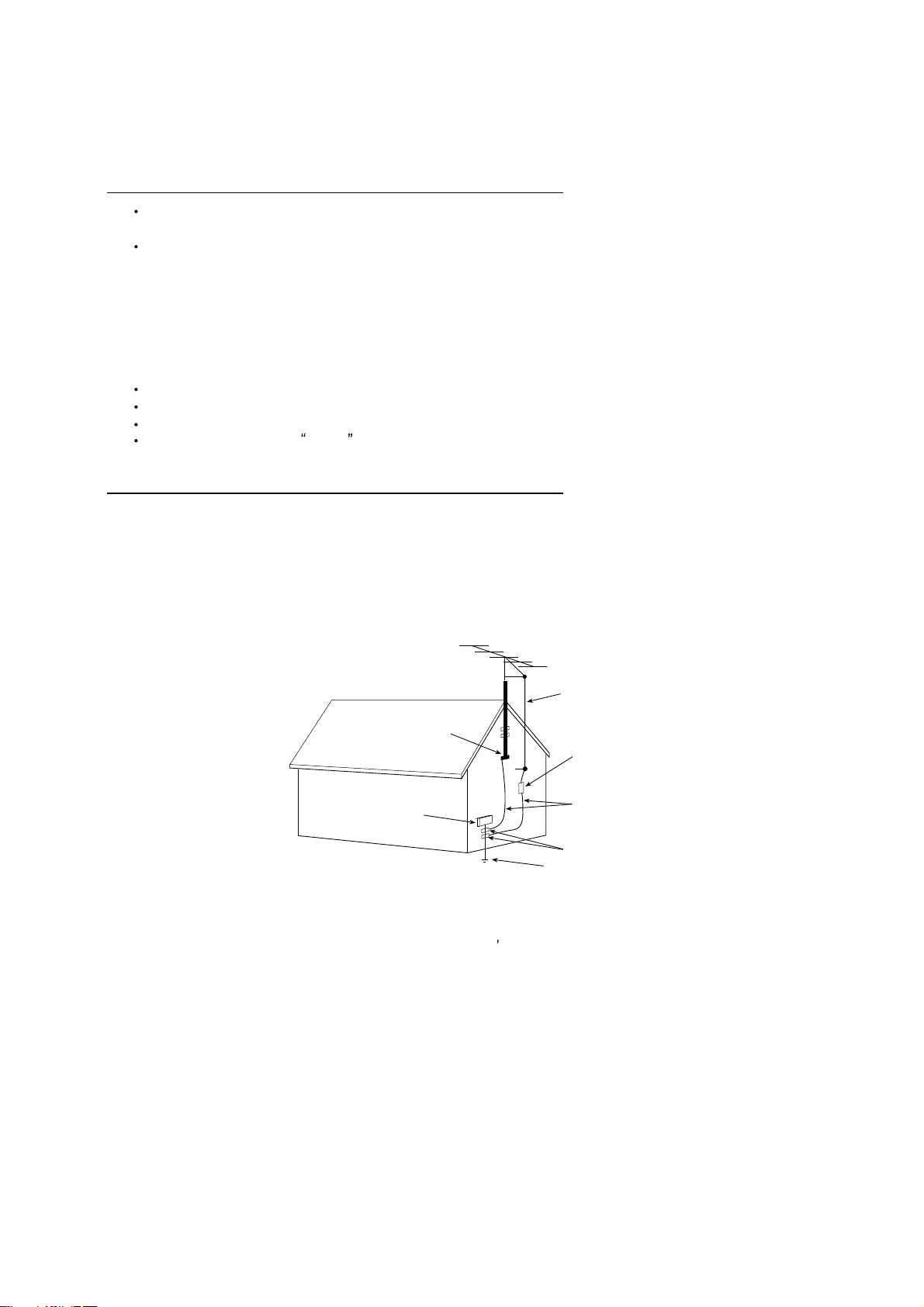
EXAMPLE OF ANTENNA GROUNDING AS PER NATIONAL ELECTRICAL CODE INSTR UCTIONS
EXAMPLE OF ANTENNA GROUNDING AS PER
NATIONAL ELECTRICAL CODE
ANTENNA
LEAD- IN WIRE
GROUND CLAMP
ELECTRIC SERVICE
EQUIPMENT
NEC-NATIONAL ELECTRICAL CODE
ANTENNA DISCHARGE
UNIT (NEC SECTION
810-20)
GROUNDING
CONDUCTORS
(NECSECTION 810-21)
GROUND CLAMPS
POWER SERVICE GROUNDING
ELECTRODE SYSTEM
(NEC ART 250. PART H)
15.2. Note to CATV system installer : (Only for the television set with CATV reception)
This reminder is provided to call the CATV system attention to Ar ticle 820-40 of the NEC that provides
installer s
guidelines for proper grounding and, in particular, specifies that the cable ground shall be connected to the grounding
system of the building, as close to the point of cable entry as practical.
16. An outside antenna system shouldnot be located in the vicinity of overhead power lines or other electric lights or power
circuits, or where it can fall into such power lines or circuits. When installing an outside antenna system, extreme care
should be taken to keep from touching such power lines or circuits as contact with them might be fatal.
17. For added protection for this television set during a lightning storm, or when it is left unattended and unused for long
periods of time, unplug it from the wall outlet and disconnect the antenna. This will prevent damage due to lightning
and power-line surges.
4
4
Page 5

SCHNEIDER ELECTRONICS GMBH-GERMANY
OPERATION OF YOUR SET
18.
This television set should be operated only from the type of power source indicated on the marking label.If you are not
sure of the type of power supply at your home, consult your television dealer or local power company. For television
sets designed to operate from battery power, refer to the operating instructions.
19. If the television set does not operate normally by following the operating instructions, unplug this television set from the
wall outlet and refer servicing to qualified service personnel. Adjust only those controls that are covered in the operating
instructions as improper adjustment of other controls may result in damage and will often require extensive work by a
qualified technician to restore the television set to normal operation.
20. When going on a holiday : If your television set is to remain unused for a period of time, for instance, when you go on
a holiday, turn the television set and unplug the television set from the wall outlet.
off
IF THE SET DOES NOT OPERATE PROPERLY
21. If youare unable to restorenormal operation by following the detailedprocedurein your operatinginstructions,
do not attempt any further adjustment. Unplug the set and call your dealer or service technician.
22. Whenever the television set is damaged or fails, or a distinct change in performance indicates a need for
service, unplug the set and have it checked by a professional service technician.
23. It is normal for some TV sets to make occasional snapping or popping sounds, particularly when being
turned on or off. If the snapping or popping is continuous or frequent, unplug the set and consult your
dealer or service technician.
FOR SERVICE AND MODIFICATION
24. Do not use attachments not recommendedby the television set manufacturer as they may cause hazards.
25. When replacementparts are required, be sure the service technician has used replacementparts specified
by the manufacturer that have the same characteristics as the original part. Unauthorized substitutions
may result in fire, electric shock, or other hazards.
26. Upon completion of any service or repairs to the television set, ask the service technician to perform
routine safety checks to determine that the television is in safe operating condition.
5
5
Page 6
EM BUSINESS CENTER
FTV PRODUCT MANAGEMENT DEPT.
SPECIFICATION RELEASE
Version: V1.0 Issued Date: 2012.02.22
Model: L32E5300/MS82S-AP/CSTM E3
PICTURE
Category
Naturalight Technology Yes (Natural Light Engine ‖)
Dynamic Contrast Yes
Color Temperature Warm / Normal / Cold
Backlight Adjustable Yes Component Video Format Y,PB/CB,PR/CR:up to 1080P
Scale Mode
Picture Effect Standard, Bright, Soft, Personal HDMI Video Format up to 1080P
Film Mode (3:2 pull down) AUTO PC Compatibility Up to SXGA
VGA Dot to Dot Display Yes (Natural)
Light Sensor
LCDTV
SIGNAL FORMAT CAPABILITY
Standard,Full, Subtitle, Wide Screen,
Zoom,Expand,Original,Natural DVI Video Format Up to XGA for HDMI-PC
TERMINALS
--
AV1 Input (Composite)
AV2 Input (Composite)
Audio/CVBS---R/L+ Video in side
Video Share with Y
and Audio share with YP
BPR Audio
Picture Enhancement YPBPR Input 1---Downward
Comb Filter 3D Audio Input for YP
Adaptive Deinterlacing 3D YC
Blue Stretch Yes Audio Input for YC
Black Stretch Yes VGA(PC) Input 1 (D-Sub,15 Pins)---Downward
Motion Compensation Yes Audio Input for VGA(PC) Share with Audio for "YP
DLTI Yes HDMI 3 (HDMI1,HDMI2,HDMI3) ---in side
DCTI Yes
Dynamic Skin Correction Yes
PANEL SPECIFICATION
Back light Unit
Panel supplier
Aspect Ratio 16:9
Panel Size (inch) 32" TV System PAL/SECAM B/G,D/K,I ;NTSC-M
Display Resolution 1366*768 AV System
Brightness (cd/m2)
Contrast Ratio 4000:1 Chassis
Response Time Tr/Tf
Viewing Angle (H/V) 178°/178° Power Supply
Life Time 30,000hrs Power Consumption-TV on
Color 16.7M Power Consumption-Standby
280 Channels
LED RF Input(Antenna) 1 (IEC Type)---Downward
CSOT Open cell+TCL BLU USB 1(Standard)---in side
6.5ms Certification
SOUND
Speakers Integrated speakers (Bottom side) Keyboard Position
Audio Power Output 2×8W Base Stand Detachable
Woofer Power Output --
Smart Volume Yes Unpackaged Dimension for Main Body (L*H*D) (mm)
Sound Effect Stereo, Music, Movie, News,Personal With Base Stand (mm) 730.5*491*183
Sound Control
Sound Features
Balance, Sound EQ Adjust; Without Base Stand (mm)
MTS(NICAM)
Scene Selecting(DeskTop mode and HangUp mode) Main Body (mm) 878*566*184
FUNCTION
OSD Language English/French/Thai/Vietnamese/Russian Base Stand
Portuguese/Arabic//Farsi/Hebrew/Mongolian Net Weight (Kg)
OSD Features Motion Bmp Style Gross Weight (Kg)
Source in OSD Source Bmp Icon Selecting,Source Jack Layout Display
Teletext Yes 20 feet
Clock/Sleep Timers Yes 40 feet
Wake up/Turn off time Yes 40 feet high
Wake up Source/Chanel Yes
Watch Time Limit Yes Operation Manual English(Default)
Startup Setting Yes(User can set a picture for turning on Logo display) Remote Control For TV control (with two batteries)
Smart Switch Yes(Signal Auto Detecting and Changing Source) Base Stand
Picture Freeze Yes Speaker Box
DNR(Dynamic Noise Reduction) Off、Low、Middle、High Wall Mount
Hotel Menu In factory mode Others AC Power cord, AV Adapter cable
USB Connection
Movie:Support H.264、RM/RMVB、XVID、FLV
DivX、MPEG2、MPEG2、MPEG4、VC1
Photo: Support JPEG、BMP、PNG;
Music: support MP3、WMA 、M4A;
Design and specifications are subject to change without notice!
BCR Input Share with "YPBPR"
CVBS Output (Composite)
SPDIF Output
Headphone Output 1 (Φ3.5mm )---Downward
BASIC INFO.
Default Color of Front Cabinet
PACKAGE INFO.
Packaged Dimension (L*H*D)
Speaker Box
Container Loading
ACCESSORIES
Drafted by:
Checked by:
Approved by:
BPR 1---Downward
BCR Share with Audio for "YPBPR"
BPR"
1 (Φ3.5mm,need a adapter cable) ---Downward
1 (coaxial digital audio output)---Downward
PAL,NTSC,SECAM
199(1~199)
MS82S-AP
CB
AC 100V-240V 50/60Hz
70W
≤1W
Black
Side
Yes
730.5*60.5*439.1
--
…
8.3kg(With Base Stand)
10kg
328
676
785
Integrated Packaging
Integrated
WMB231(Optional)
曾祥正 (HW)2012-02-22
Page 7

TCL Multimedia Technology Holdings Ltd.
R&D Center
Alignment Procedure
MS82S-AP/LA Chassis
Version: 1.0
Release Date: 2011-9-6
PREPARED BY: Wise Zhang
APPROVED BY:
DATE: 2011-9-6
DATE:
Page 8
MS82S-AP/LA Chassis Software Upgrade Guidance
Content
1. General Description 3
2. Factory Menu 3
2.1 Way of accessing 3
2.2 Factory Menu 4
2.3 ADC calibration menu 5
2.4 White Balance adjustment 6
3. Design Menu 7
3.1 way of accessing 7
3.2 SHOP Menu 8
3.3 Other Menu 9
3.4 Service Menu 10
3.5 PARAM SETTING MENU 11
3.6 Hotel Menu 12
4. Steps of debugging 13
4.1 Device 13
4.2 steps of debugging 13
4.3 ADC calibration 13
4.4 White Balance adjustment 14
4.5 White Balance adjustment (automatically) 16
5. Chip list of software programming before SMT 16
6. Appendix 17
6.1 Software upgrading through USB 17
6.2 Check software version, release date and Project ID 18
6.3 FAQ 20
History Description of major changes Release
Date
V1.0 2011-9-7
Chassis Model
FHD MS82S-AP/LA L40D3260F etc
HD MS82S-APLA L32D3260, L32D3270 etc
PRELIMINARY INFORMATION ----- SUBJECT TO CHANGE
2
Page 9

MS82S-AP/LA Chassis Software Upgrade Guidance
1. General Description
MS82S-AP/LA is our latest design especially for LCDTV products selling in Asia
Pacific (AP) and Latin America (LA) market. It features by its high integration,
easy debugging as well as convenience in terms of maintenance. Fast software
upgrade through USB disk facilitates both manufacture and after-sale service.
Meantime, a variety of functions involved in Factory Main Menu can not only
bring benefits for production, but also satisfy various demands of customer.
Note: Factory Main Menu (FMM) is divided into Factory Menu, Design Menu, Service
Menu and Hotel Menu. Factory Menu covers all indispensable functions during
manufacture such as White Balance Adjustment, ADC Calibration, USB Upgrading e.g.,
while the items under Design Menu is exclusively used by R&D engineer, anyone else
shouldn’t change the settings in the menu. When you wish to learn the product
information like project ID, model name, chassis name, software version, release date,
you can access to Service Menu. In addition, in Hotel Menu, we also provide a great
deal of useful functions for specific applications in hotel.
2. Factory Menu
2.1 Accessing way:
a. In the first place, press Menu button of
remote
control, then select Contrast item of Picture
submenu. Finally, press 9, 7, 3, 5 consecutively.
b. When the FAC HOTKEY item o f Factory Menu
is enabled (ON), press Return button of remote
control.
PRELIMINARY INFORMATION ----- SUBJECT TO CHANGE
3
Page 10

MS82S-AP/LA Chassis Software Upgrade Guidance
2.2 Factory Menu
Factory Menu
Name Default Description Status
FAC
HOTKEY
OFF Factory Menu shortcut button switch
The item must be disabled (OFF) after production
OK
WARM-
UP
ADC >> ADC calibration ( see details below) OK
WHITE
BALANCE
SHOP
NVM RESET DO Restore default value except WB and ADC data. OK
SET FAC CH DO Preset the channel table of factory. Option: HZ, WX, EGYPT-EL,
Power On
Mode
OFF OFF: Normal mode. Display blue screen when no signal. Turn to
automatically standby mode if keep the signal unavailable over
15 minutes.
ON: Aging mode. Display snow dot when no signal. The set will not
turn to standby even if the unavailability of signal
>> White Balance Adjustment ( see details below) OK
DO It is crucial that the function is executed after production aim to clear
information of production process, ensure user cannot access to
Factory Menu after executing the item.
ALGERIA e.g. To p reset th e ch an nel table of certain factory, firstly,
choose the corresponding factory name, then press OK button of
remote control and wait until the disappearance of Factory Menu,
LAST/STB ON: the set will power on after switching on power.
STB: the set will remain standby status after switching on power.
Last: the set will turn to the status in which it lies when last switching
off.
If without requirement from certain customer,
OK
OK
OK
OK
by default, the Setting should be Last for MS82S-AP and STB for
MS82S-LA
USB
UPDATE
SW NO. OFF Version information of Main Software OK
Project
Name
SIACP
Version
Date Release date and time of main software OK
Upgrade software. Please see details below. OK
Product model OK
Serial port remote control protocol OK
PRELIMINARY INFORMATION ----- SUBJECT TO CHANGE
4
Page 11
MS82S-AP/LA Chassis Software Upgrade Guidance
2.3 ADC calibration menu
ADC Menu
Press the button in remote control to select certain
item and
ADC calibration.
Notes:
1. Only YPBPR and RGB source should be calibrated.
to change the value of ADC data or start
ADC Calibration menu
Name Default Description Status
SOURCE Select the source you intend to ADC Calibrate.
R GAIN 4096 Gain of R channel ( cannot be changed after auto calibration) OK
G GAIN 4096 Gain of G channel ( cannot be changed after auto calibration) OK
B GAIN 4096 Gain of B channel ( cannot be changed after auto calibration) OK
R OFFSET 0 Offset of R channel ( cannot be changed after auto calibration) OK
Only YPBPR and RGB are available.
OK
B OFFSET 0 Offset of B channel ( cannot be changed after auto calibration) OK
G OFFSET 0 Offset of G channel ( cannot be changed after auto calibration) OK
AUTO ADC DO Select and execute the item, ADC Calibration starts. It indicates
ADC
STATUS
Show the ADC status of YPbPr/RGB Channel. SUCCESS will be
a successful calibration if prompt “OK” is displayed.
Otherwise, It is a failing calibration (“FAIL” is displayed).
display if YPbPr/RGB Channel has been correctly calibrated.
Otherwise FAIL will be displayed
OK
OK
PRELIMINARY INFORMATION ----- SUBJECT TO CHANGE
5
Page 12
MS82S-AP/LA Chassis Software Upgrade Guidance
2.4 White Balance Adjustment menu
White Balance menu
Press the button in remote control to select
certain item and
to adjust White Balance
White Balance Adjustment menu
Name Default Description Status
Source PC Select the source you intend to apply WB adjustment.
COLOR
TEMPERATURE
R GAIN
G GAIN
B GAIN
R OFFSET
Cool Select color temperature you intend to adjust Three groups of
-2
0
+9
+6
Only HDMI1, AV1, YPBPR, PC and should be adjusted.
color temperature: Normal, Warm, Cool are available for each
source.
Gain of R channel ( cannot be changed after auto calibration) OK
Gain of G channel ( cannot be changed after auto calibration) OK
Gain of B channel ( cannot be changed after auto calibration) OK
Offset of R channel ( cannot be changed after auto calibration) OK
OK
OK
G OFFSET
0
Offset of G channel ( cannot be changed after auto calibration) OK
B OFFSET
-2
Offset of B channel ( cannot be changed after auto calibration) OK
WB INIT
PRELIMINARY INFORMATION ----- SUBJECT TO CHANGE
White Balance Initalization. Before WB adjustment, this item should
be executed.
OK
6
Page 13
MS82S-AP/LA Chassis Software Upgrade Guidance
3 Factory Main Menu
3.1 Accessing way:
1. In the first place, press Menu button of
remote control, then select Contrast item
of Picture submenu. Finally, press 1, 9, 5, 0
consecutively.
2. When the DESIGN HOTKEY item of Design
Menu is enabled (ON), press Return button of
remote control.
Press the button in remote control to select
certain item and to toggle among or execute the
available options.
Main Menu
Name Default Description Status
DESIGN
HOTKEY
FACTORY
MENU
SHOP
INIT
OTHER
SERVICE
MENU
PARAM
SETTING
HOTEL
MENU
PRELIMINARY INFORMATION ----- SUBJECT TO CHANGE
OFF Design Menu shortcut button switch
The item must be disabled (OFF) after production
>>> Access to Factory Menu OK
>>> Contain many options which can be chosen according to the
requirements of customers as default settings when leave factory.
See details below.
>>> The item includes a number of functions offering convenience for
R&D engineer to solve problems. It is exclusively used by R&D.
>>> Provide many useful information for aftersale service
Please reference to SERVICE MENU submenu
>>> Include volume, brightness, contrast, saturation, hue, sharpness,
backlight, volume, overscan Adjustment etc. Please reference to
PARAM SETTING submenu.
>>> Include special functions which bring benefits to hotel management.
The item is accessible only when HOTEL ENABLE item is enabled
(ON).
OK
OK
OK
OK
OK
OK
7
Page 14
MS82S-AP/LA Chassis Software Upgrade Guidance
3.2 SHOP MENU
Contain many options which can be chosen according
to the requirements of customers as default settings
when leave factory. Press the
control to select certain item and
among the available options..
button in remote
to toggle
SHOP MENU
Name Default Description Status
VOLUME 30 Volume setting, 0~100 adjustable OK
PIC MODE STANDARD Picture mode. Options:
SOUND
MODE
STEREO Sound effects. Options:
BRIGHT, SOFT, PERSONAL,STANDARD
STAREO MISIC, MOVIE, NEWS
OK
OK
CH NUMBER 199 Maximum number of accessible channel NG
OSD
LANGUAGE
Preset CH 0 Preset channel. 0~199 optional OK
ENGLISH AP: English, French, Vietnamese, Russian, Arabic, Farsi, Hebrew,
Thai, Portuguese, Mongolian, LA: English, Portuguese, Spanish
OK
COLOR
TEMP
NORMAL Color temperature. Option: NORMAL, WARM, COOL OK
PRELIMINARY INFORMATION ----- SUBJECT TO CHANGE
8
Page 15

MS82S-AP/LA Chassis Software Upgrade Guidance
3.3 Other Menu
Press the
certain item and to toggle among the available
options..
button in remote control to select
Other Menu
Name Default Description Status
VIF1 Exclusively used by R&D. OK
VIF2 Exclusively used by R&D. OK
VIF3 Exclusively used by R&D. OK
QMAP
ADJUST
SSC Spectrum Spread Control.
DBC
ENABLE
BP Parameter of DBC
CP Parameter of DBC
DBC MODE DBC Mode. Exclusively used by R&D. OK
MU0 DQS0 Manually adjust DQS1 phase of DDR2
PRELIMINARY INFORMATION ----- SUBJECT TO CHANGE
Exclusively used by R&D. OK
OK
Exclusively used by R&D.
Dynamic Backlight Enable
Exclusively used by R&D.
Exclusively used by R&D.
Exclusively used by R&D.
Exclusively used by R&D
OK
OK
OK
OK
9
Page 16

MS82S-AP/LA Chassis Software Upgrade Guidance
MU1 DQS1 Manually adjust DQS1 phase of DDR1
Exclusively used by R&D
TTX ON ON: enable teletext OFF: Disable teletext OK
OK
3.4 SERVICE MENU
Press the
item and
button in remote control to select certain
to toggle among the available options..
SERVICE MENU (Product Info)
Name Default Description Status
SW NO. Software virtual code of Main Software OK
DATE Release date, time OK
Project Name Model of product OK
SIACP
Version
Chassis MS82S-AP/MS82S-LA Chassis name OK
Serial port remote control protocol
OK
P ANEL NAM E Panel code OK
PROJECT ID Select project parameters through project ID. OK
USB UPDATE USB upgrade. OK
HOTEL
ENABLE
Switch of Hotel Menu. OK
PRELIMINARY INFORMATION ----- SUBJECT TO CHANGE
10
Page 17

MS82S-AP/LA Chassis Software Upgrade Guidance
ERROR
CODE
TCL_LOGO Display TCL Logo or not. On : display,
LOGO_LIGHT OK
TCL_SHOW DEMO function ON/OFF OK
NG
OK
Off: not display
3.5 PARAM SETTING MENU
Press the
and
button in remote control to select certain item
to enter menu.
PARAM SETTING MENU (Setting menu)
Name Default Description Status
Brightness
Curve
Contrast
Curve
Saturation
Curve
>>> Brightness curve. Exclusively used by R&D. OK
>>> Contrast curve. Exclusively used by R&D. OK
>>> Saturation curves. Exclusively used by R&D. OK
Hue Curve >>> Hue Curve Exclusively used by R&D. OK
Volume
Curve
>>> Volume curve. Exclusively used by R&D. OK
Backlight
Curve
OverScan >>> Overscan adjustment. Exclusively used by R&D. OK
PRELIMINARY INFORMATION ----- SUBJECT TO CHANGE
>>> Backlight curve. Exclusively used by R&D. OK
11
Page 18

MS82S-AP/LA Chassis Software Upgrade Guidance
3.6 HOTEL MENU
Press the
certain item and
button in remote control to select
to enter submenu.
Name Default Description Status
POWER
LOGO
CH LOCK OFF Channel scan lock. OK
ON LOGO select OK
HOTEL MENU
MAX VOL 100 Max volume OK
AUTO SET OFF The switch of PIC, SOUND etc.
PIC MODE Standard Picture mode. OK
SOUND
MODE
POWER
VOL.
POWER
SIGNAL
POWER
CHANNEL
KEY LOCK OFF Lock the keys. OK
SA VE DATA
TO
WRITE
DATA TO
PRELIMINARY INFORMATION ----- SUBJECT TO CHANGE
STEREO Sound mode OK
50 Default volume when power on OK
ATV Default signal source when power on OK
0 Default channel no. when power on OK
DO Save the settings of Hotel M enu to USB OK
DO Copy the settings of Hotel Menu from USB OK
When it is ON, these items are selectable.
OK
12
Page 19

MS82S-AP/LA Chassis Software Upgrade Guidance
g
p
g
ging
4. The steps of debuggin
4.1 Device
Color Analyzer CA-210. Video Pattern Generator Chroma2329. Color TV Pattern
Generator PM5418, VGA cable, AV cable(RCA),YPBPR(RCA) cable.
。
Chroma2329
4.2 ste
s of debu
Fluke5418 CA-210
:
According to the requirement of order, we suggest take the below steps to finish
the appropriate settings.
A enter the Factory Menu, enable FAC HOTKEY
B Check the version of software, release date displayed at the bottom of Factory
Menu. If the information is correct, you can ignore step C and D.
C Enter Factory Main Menu, choose SERVICE MENU->PROJECT ID, choose
corresponding Project ID number of the product (Please refer to the description in
BOM about Project ID number).
D return to Factory Menu, check the Product model.
E choose Factory Menu-> NVM RESET and press and wait until prompt OK
appears.
F restart the set
G according to the requirement of order, set the items of Shop Menu and Hotel
Menu etc.
H After aging under normal temperature, calibrate ADC and adjust white balance.
I choose Factory Menu-> SHOP INIT and press button of remote control to
initialize the set.
Note: after step I (execute SHOP INIT), Hotel Menu will be disabled by default.
Therefore, if order requires hotel function, it is necessary to enable hotel function by
Factory Main Menu-> Service Menu->HOTEL ENABLE to ON.
set
4.3 ADC Calibration
Ⅰ.signal and generator
VGA: Chroma2329 Pattern42, Timing 14(1024x768@60Hz 5 MOSAIC)
YPBPR: Chroma2329 Pattern103, Timing 79(100% Color Bar, 720p)
5 MOSAIC 100% Color Bar
PRELIMINARY INFORMATION ----- SUBJECT TO CHANGE
13
Page 20

MS82S-AP/LA Chassis Software Upgrade Guidance
Ⅱ.steps of debug:
1) Access to the Factory menu->ADC
2) Select PC source
3) Select AUTO ADC,Press button in your remote control to calibrate the
ADC automatically.
4) Select YPBPR source
5) Repeat step 3.
6) When the OK appears the calibration has been finished successfully.
VGA calibration YPBPR calibration
4.4 White Balance adjustment (Manual)
Before adjustment, you must ensure Color Analyzer has been calibrated. Only AV1,
YPBPR, VGA , HDMI 1 need to be adjusted. It is necessary to adjustment HDMI 1
firstly.
a. signal and generator
The pattern of the signal should be used are White (Chroma2329 pattern113) and
Grey (pattern 114).The format of signal are respectively 720p for HDMI1
(Chroma2329 Timing 69), NTSC for AV1 (Chroma2329 Timing 37),1024×768@60Hz
(Chroma2329 Timing 14) for VGA and 720p (Chroma2329 Timing 79)for YPBPR
b. steps of adjustment
1) enter the factory menu->WHITE BALANCE, select source HDMI 1 and COLORTEMP
normal.
2) input grey signal in 720p format
3) change R OFFSET and B OFFSET to make sure the value of color coordination
equal to the value required by enterprise standard (x, y).
PRELIMINARY INFORMATION ----- SUBJECT TO CHANGE
14
Page 21

MS82S-AP/LA Chassis Software Upgrade Guidance
4) input white signal in 720p format
5) change R Gain and B Gain to make sure the value of color coordination equal to
(x, y).
6) repeat step 2~5 until both of the value of color coordination of white and grey
equal to (x, y).
In addition to select COLORTEMP COOL/WARM, the adjustment method of COOL
and WARM color temperature is same with that of NORMAL. The color coordination
we recommend is as follows:
Device:CA-210; Accuracy:±0.015
Color Temperature
x
LCD
y
x
LED
y
WARM NORMAL COOL
0.300 0.280 0.270
0.305 0.290 0.270
0.302 0.282 0.272
0.317 0.302 0.282
HDMI White Balance adjustment
PRELIMINARY INFORMATION ----- SUBJECT TO CHANGE
15
Page 22

MS82S-AP/LA Chassis Software Upgrade Guidance
4.5 ADC Calibration and White Balance Adjustment (automatic)
The process of adjusting ADC and White Balance automatically is out of the range
of this file. Please refer to the relevant technical file of HuiZhou factory of TCL
5. Chip list of software programming before SMT
Following chips must be programmed before SMT by ALL-11 or other tools.
Position Chip type Chip name Part number Software
description
1 U502 Flash
2 U503 E2PROM M24C64 13-M24C64-W6B HDCP KEY SO-8
Note:
1) The software for U502 and U503 can be program using ISP tool.
2) Every set has its unique HDCP key which is purchased from suppliers or HDCP
certification authority. Please check HDCP function in the process of production.
3) Once in a while, the software of main board may be upgraded. Please pay attention to
use the latest software before production.
EN25Q3 13-EN25Q3-2AB
main software SO-8
Decal
PRELIMINARY INFORMATION ----- SUBJECT TO CHANGE
16
Page 23

MS82S-AP/LA Chassis Software Upgrade Guidance
Appendix:
1. Software upgrade through USB disk
1) Please ensure the software you are using has a correct file name
TCL_MS82_UPDATE.bin, then copy it to the root directory of a USB disk.
2) Insert the USB disk to the USB socket of the set for which you are
going to upgrade program.
3) Enter the Factory Menu (you can choose either a or b way below)
a. In the first place, press Menu button of remote
control, then select Contrast item of Picture
submenu. Finally, press 9, 7, 3, 5 consecutively.
b. When the Factory hotkey ite m of Factory Menu
is enabled (ON), press Return button of remote
control.
4) select USB UPDATE, press buttonof remote control, a pop menu
will appear prompting whether start upgradeor not. Press Yes to start upgrade,
press No to canel. Please wait patiently until the set restart automatically after
upgrade. Do not cut off the power supply during the process.
Upgrade Main Software
PRELIMINARY INFORMATION ----- SUBJECT TO CHANGE
17
Page 24

MS82S-AP/LA Chassis Software Upgrade Guidance
2. Check software version, release date and Project ID
After upgrading, sometimes you may not certain whether the new software has
been successfully updated or not. In this case, you can check the software version
and release date in Factory Main Menu to make sure the success of upgrading.
In addition, for the convenience of software management, many models of same
chassis may share a same software, but are allocated with different Project ID.
In another words, every model has its unique Project ID. Obviously, Both software
version and Project ID are highly critical to ensure the set work properly. Therefore,
after upgrading software,we suggest you check these information by following
method.
1) Enter the Factory Main Menu(you can choose either a or b way below
a In the first place, press Menu button of remote control, then select Contrast item
of Picture submenu. Finally, press 1, 9 5, 0 consecutively.
b. When the DESIGN HOTKEY item of Factory Main Menu is enabled (ON), press
Return button of remote control.
2) Check the version of software, release date displayed at the bottom of Factory
Main Menu. If the information is correct, you can ignore step C and D.
3) choose SERVICE MENU->PROJECT ID, choose corresponding Project ID number of
the product (Please refer to the description in BOM about Project ID number).
4) choose Factory Menu and press OK button of the remote. Next, select NVM RESET
and press and wait until prompt OK appears.
5) choose SHOP INIT and press
button of remote control to initialize the set.
Note: after step I (execute SHOP INIT), Hotel Menu will be disabled by default.
Therefore, if order requires hotel function, it is necessary to enable hotel function by
set
Factory Main Menu-> Service Menu->HOTEL ENABLE to ON.
6) restart the set.
PRELIMINARY INFORMATION ----- SUBJECT TO CHANGE
18
Page 25

MS82S-AP/LA Chassis Software Upgrade Guidance
Product
Information
Check product information
Remote Control name
Power Supply name
Audio Channel number
Change project ID
PRELIMINARY INFORMATION ----- SUBJECT TO CHANGE
19
Page 26

MS82S-AP/LA Chassis Software Upgrade Guidance
3. FAQ
1) Why there is no picture after upgrading software or changing project ID?
It may be caused by fault of project ID. You can try below method to fix
the problem.
a. If the resolution of the panel of your set is 1366×768(HD panel), you can press
Menu, and 4976 of remote control in series after turning on.
b. If the resolution of the panel of your set is 1920×1080(FHD panel), you
can press Menu, and 4973 in series after turning on.
c. If you can see the picture at this time, please recheck the project ID again. If
the project ID is still wrong, correct it reference to above description.
PRELIMINARY INFORMATION ----- SUBJECT TO CHANGE
20
Page 27

TU1
TUNER
AP:07-380FI5-NK4G
LA:TBD
TU1_IFTU1_IF+
Tuner I2C BUS
Band Pass Filter
RF_AGC
TU1_IF- IN
TU1_IF+ IN
AMP L/R
Q601/Q602
Audio Amplifier
VIDEO OUTPUT
Q300/Q301
Video Amplifier
U602
Earphone AMP
13-DRV632-00B
U601
Audio Amplifier Power
13-TPA311-D2B
SPDIF OUTPUT
VIDEO OUTPUT V/ L/R
Earphone L/R
P603:47-EAR030-XX0
L Channel
R Channel
>32': 8W
<26': 5W
P305:47-RCA301-XB0G
P400:47-VGA021-XX0
P302:47-RCA303-XG0G
P301:47-RCA302-XR0G
P300:47-RCA303-XY0G
P401:47-HDI011-KS0
P402:47-HDI011-KS0
P403:47-HDI011-KS0
P303:47-USB002-XX0
PC/VGA/YPBPR/AV2 Audio INPUT
HDMI 1 INPUT
HDMI 2 INPUT
HDMI 3 INPUT
PC/VGA INPUT:R/G/B/HS/VS
YPBPR/AV2(Video) INPUT
AV1 INPUT
U400
HDMI SW
13-T6633E-00B
USB INPUT
TMDS/DDC/DET
U500
Main-chipset
AUDIO OUTPUT
LVDS Odd Signal
LVDS Even Signal
SPI BUS
I2C BUS
Q302/Q303
Audio Amplifier
U501
DDR2 SDRAM
13-K4T511-F7B
U502
FLASH MEMORY
13-EN25Q3-2AB
U503
EEPROM
13-M24C64-W6B
LCD Panel
BL_ON
DIM
P304:47-EAR032-XX0
12V or 5V
24V
3V3STB
Power
AC
Supply
DC 12V
Unit
DC 24V
Note:
Some PSU output DC 24V&3V3STB, some output
DC 12V&3V3STB.
PW_ON/OFF
EARPHONE_MUTE
DC 24V
DIM
AMP-MUTE
PANEL_ON/OFF
Power Supply Block Diagram
U100
DC/DC
13-RT8110-B0B
24/12V-SW
Q104
PW_ON/OFF
BL_ON
LED_OUT
HDMI_DET
Q100
MOSFET
12-04822A-0BX
U601
Audio Amplifier Power
13-TPA311-D2B
IR_IN
LIGHTSENSOR
HWRESET
DC 12V
12V
or 5V
KEY IN
RXD/TXD
3V3STB/1V28/1V8/2V5/3V3
12V 5V
U101
DC/DC
13-MP1482-DSB
Panel_Vcc -SW
Q106
PANEL_ON
Panel_Vcc
U105
LDO
13-AS1117-33B
U103
LDO
13-AS1117-25B
U106
LDO
13-AS1117-18B
U104
DC/DC
13-MP2127-DQB
Low Pass Filter
+3V3(225mA)
+2V5(210mA)
+1V8(200mA)
VDDC-1V28(680mA)
TUNER_5V(80mA)
MS82S (AP&LA) Chassis Block Diagram
First Issued V0.1
ZCX 2011-09-07
Page 28
7
D D
6
MODEL:
5 4 3 2 1
01-MS82S0-MAC2XG
DESCRIPITION:
C C
DRAWN:
B B
CHECK:
APPR:
A
THIS DRAWING CANNOT BE COMMUNICATED TO UNAUTHORIZED PERSONS COPIEDUNLESS PERMITTED IN WRITING
7
6
5 4 3 2 1
DATE:
DATE:
DATE:
TCL
WW R&D CENTER TCL MULTIMEDIA TECHNOLOGY HOLDING LTD.
5TH FLOOR.TCL BUILDING.SOUTH NANHAI ROAD
NANSHAN DISTRICT.SHENZHEN.GUANGDONG 518067 CHINA
TEL:+86 755 33312403
NOTE:
...........
PAGE: OF
FORMAT DIN A4
A
Page 29

12 11 10 9 8 7 6 5 4 3 2 1
H
24/12V_IN
BL_ON/OFF
C124
3_3V/5VSB
T
C101
0.1U
DIM
GND7
T
DGND
10P
R152
0R
DIM
DIM_PWM
3.3V/5VSB
DGND
DGND
24V/12V
T
DGND
P100
11
9
7
5
3
1 2
G
DGND
T
P_ON/OFF
T
12
10
8
DGND
6
4
BL_ON
POWER_ON
DIM_DC
24V/12V
24V/12V
C100
DGND
DGND
T
0.1U
DIM_DC
T
L108
33R
L109
33R
24/12V_IN
35-392170-00X
L112
33R
L114
33R
12V
12V
V_AUDIO
L107
R102
NC/0R
R103
NC/0R
1%
1%
12V
24/12V_IN
0.1U
C105
DGND
C106
0.1U
RT8110B
BOOTFBUGATE
5
VIN
7
8
LL4148
D102
GNDPHASE
LGATE
VCC
U100
A04822A
G2
4
36
2
1
DGND
C107
2U2
4
S2
3
G1
S1
2
1
Q100
D2B
D2A
D1B
D1A
5
6
7
8
R101
10R
C122
C104
R104
10R
1000P
0.1U
NC/
24V
T
C102
DGND
220U
35V
C110 0.1U
T
10U
C109
DGND
12V
C108
220U
16V
1U
C103
L104
10UH
VOUT=0.8X(1200+820+27)/(820+27)=12.13V
VOUT=12.13V
R106
12K
R107R108
820R
150P
C126
12V
12V
C114
DGND
0.1U
0.047U
C115
2K2
R109
DGND
C116
0.1U
H
12V
R110
100K
U101
8
SS
7
EN
5
FB
MP1484
VOUT=0.923X(51+11)/11=5.2V
BS
SWCOMP
GND
1
2
IN
36
4
DGND
0.1UC113
L100
15UH
0.1UC112
R111
R112
DGND
DGND
51K
11K
10U
C111
C117 0.1U
C120
16V
NC/
DGND
220U
10U
C118
5V
C119
16V
470U
5V
5V
T
G
C131
GND/ADJ
1
R192
10R
DGND
Need PCB Heatsink
T
2V5
2U2
0.1U
C132
Need PCB Heatsink
T
R193
NC
C168
0.1U
+1V8
C170
210mA
C133
16V
100U
+2V5
6M48:469mA
6M182:200mA??
C171
16V
10U
100U
+1V8
DGND
27R
5V
5V
C165
DGND
10U
C135
0.1U
3.3V/5VSB
3.3V/5VSB
4
5
PGOOD
6
MP2127
PVIN
VIN
3
IN OUT
0.1U
C123
NC/
SW
GND
FB
U104
R121
0R
U102
RT9166-33
GND
1
NC
F
VDDC-1V28
1_28V
10U
T
VOUT=1.285V
C140
6V3
470U
VDDC-1V28
680mA
L106
33K
R126
R127
3K3
4.7UH
DGND
22K
R128
0.1U
C141
DGND
VOUT=0.8X(22+33+3.3)/(33+3.3)=1.285V
C142
3
2
1
E
DGND
+3_3VSTB
+3_3VSTB2
2U2
NC/
C127
16V
100U
T
D
2
C125
0.1U
100mA
C177
24V/12V
Q104
1
S1
2
22K
R138
C148
DGND
B
0.1U
NC/
NC/
R168
C
E
R140
DGND
4K7
NC/
Q103
C124ET
1K
NC/
/NC
F
POWER_ON_OUT
(5)
R118
1K
B
+3V3
+3V3
C
E
DGND
Q101
BT3904
R113
10K
+3V3
+3V3
R114
4K7
10K R115
NC
E
BL_ON_OUT
R190
NC/10K
3.3V/5VSB
R136
R130
100R
10K
NC/
R137
NC/
BL_ON
C143
4K7
0.01U
R169
3K3
NC/
S2
3
S3
4
G
NC/
C149
NC/
D
R178
(5)
DIM_OUT
R179
10K
1K
R173
1K
DIM
2U2
C159
DIM_DC
PMK50XP
0.1U
8
D1
7
D2
6
D3
5
D4
1
C145
4
GND/ADJ
2
2U2
NC/
4
OUT
3
U105
AS1117-3.3
VIN
0.1U
C146
+3V3
T
C147
2U2
+3V3
+3V3
225mA
C172
16V
100U
Need PCB Heatsink
5V
5V
0.1U
C144
DGND
DGND
AS1117-2.5
5V3
T
5V
R191&R194 PCB overlap
5V
R191
NC/2W
3R3
R194
2R7
U103
C130
U106
AS1117-1.8
5V-DDR
T
VIN
3
0.1U
DGND
2U2
C167
NC/
4
4
OUT
2
VIN
3
C166
0.1U
GND/ADJ
1
10R
R123
4
4
OUT
2
SENSOR
T
R149
NC/
IR
100P
4K7
5V
C154
R151
NC/
R155
0R
0.1U
10R
0.1U
C150
NC/
DGND
5V2
T
LOGO
T
LED
T
T
GND2
F100
C151
DGND
0.1U
NC/
T
C153
LIGHTSENSOR_OUT
LOGO_OUT
+3_3VSTB
(5)
LED
IR
C155
DGND
R154
4K7
0.1U
NC/
+3_3VSTB
R153
4K7
R162
100R
R163
100R
DGND
IR_IN
LED_OUT
(5)
(5)
P102
4
3
2
1
GND3
T
5VOUT
DGND
F101
DGND
+3_3VSTB1
T
5V4
T
KEY_IN
DGND
DGND
+3_3VSTB
R167
NC/
R166
NC/
C157
DGND
10R
4K7
1000P
LOGO_OUT
KEY_IN
5V
(5)
R164
T
KEY
0.1U
C156
NC/
100K
+3_3VSTB
DGND
0.1U
NC/
R165
4K7
C152
C
R186
0.1U
B
DGND
22K
4K7
R189
C
E
R185
Q106
PMV65XP
S
Q107
BT3904
1K8
PANEL_VCC
PANEL_VCC
T
D
G
C163
0.1U
PANEL_VCC
P101
7
6
5
4
3
2
+3_3V-STB
1
+3_3VSTB3
DGND
IR
T
L_SENSOR
LOGO
5V
LED
DGND
DGND
5V
12V
C
P103
PANEL_ON
(5)
B
5V
3K3
R180
R188
NC/0R
R187
0R
1%
1%
C161
3
2
1
R183
4K7
1K
DGND
R120
100R
POWER_ON_OUT
(5)
DGND
+3_3VSTB
R116
A
THIS DRAWING CANNOT BE COMMUNICATED TO UNAUTHORIZED PERSONS COPIED UNLES S PERMITTED IN WRITING
POWER_ON
C164
DGND
0.1U
...
...
...
...
Index-Lab
Last saved :
DD-MM
DD-MM
DD-MM
DD-MM
...
...
...
...
...
...
SBU :
TCLNO:
TCL
ADDRESS1
...
...
...
.............
ADDRESS2
A
ADDRESS3
...
...
NAME Last modifDESCRIPTIONDATE
8-11-2011_18:06
...
DESIGNATION
...........
ON:
BY:
33312841
DRAWN
CHECKED
DD-MM-YY
ON:
BY:
......
PAGE:
OF :
123456789101112
Page 30

8 7 6 5 4 3 2 1
DGND
C216
0R
C213
33R
NC
F
E
TU1
NC1
1
+30V
T
NC2
2
AGC
T
TU1_VCC
NC3
RF-AGC
3
4
TU1_BT
TU1_RFAGC
T
B+
SDA
596
TU1_SDA
TUNER_5V
SCL
NC4
7
8
T
TU1_SCL
SDA1
T
NC5
SCL1
IF+
IF-
10
11
TU1_IF-
T
TU1_IF-
T
TU1_IF+
TU1_IF+
C204
56P
NC/
56P
C205
NC/
TU1_IF-
TU1_IF+
C203
0.1U
C206
0.1U
L201
L203
0R
0R
NC
L202
NC
C207
C210
L206
NC
0R
L204
NC
C220=220PF,BPF FOR 38.9MHz OR 38MHz,PAL
C220=120PF,BPF FOR 45.75MHz,NTSC
L208
C221
33R
L207
NC
NC
0.1UH
L209
C217C220
220P
NC
C224
DGND
C218
C219
51R
51R
D
C222
C223
0.1U
0.1U
L211
L210
0R
0R
TU1_IF-_IN
F
TU1_IF+_IN
E
D
DGND
Near Tuner
Near Tuner
R201
100R
TU1_RFAGC
C
0.1U
C201
DGND
B
RFAGC
TUNER_5V
TUNER_5V
0.1U
C202
DGND
C208
10U
C233
6V3
470U
L212
NC/100UH
R203
2R2
R202
2R2
5V
TU1_SCL
TU1_SDA
TUNER_5V
R213
4K7
22P
C214
R214
4K7
22P
C215
DGND
R215
100R
R216
100R
C
TUNER_SCL
TUNER_SDA
B
A
THIS DRAWING CANNOT BE COMMUNICATED TO UNAUTHORIZED PERSONS COPIED UNLES S PERMITTED IN WRITING
...
...
...
...
DD-MM
DD-MM
DD-MM
DD-MM
DATE DESCRIPTION Last modifNAMEIndex-Lab
Last saved :
...
...
...
...
...
...
...
...
4-14-2009_15:30
45678
...
...
...
...
TCL MULTIMEDIA TECHNOLOGY HOLDINGS LTD
SBU :
TCLNO:
.............
DESIGNATION
01-MS8200-MAA2XG
ADDRESS1
ADDRESS2
ADDRESS3
TELEPHONE
DRAWN
ON:
BY:
TCL
CHECKED
DD-MM-YY
ON:
BY:
......
A
PAGE:
OF :
123
FORMAT DIN A3
Page 31

8 7 6 5 4 3 2 1
YELLOW
F
WHITE
E
D
AVOUT1_V
C
AV IN 1
P300
RED
R340
75R
6
5
4
3
2
1
BT3906
Q300
GND6
T
F300
AV1_V
T
AV1_V
F301
E
C
AV1_L
T
AV1_L
T
AV1_R
F302
B
BT3904
R341
180R
AV1_R
R342
Q301
75R
R306
3K3
R343
150R
DGND
E
C
R301
10K
R302
10K
DGND
B
close to IC
R300
33R
12K
R307
33K
R345
68K
C325
12K
C300 470P
R344
0.047U
C326
C327
R308
0.1U
C315
DGND
2U2
2U2
C301
470P
R351
10R
AV1_V_IN
AV1_L_IN
AV1_R_IN
5V
C317
100U
16V
R359
NC/
15K
(5)
(5)
(5)
YPBPR_IN
RED
WHITE
P301
RED
BLUE
GREEN
CVBS_OUT
(5)
P302
1
2
3
4
1
2
3
4
5
6
GND9
T
DGND
HD_R
F303
HD_L
F304
HD_PR
F305
HD_PB
F306
HD_Y
F307
HD_R
T
HD_R
DGND
DGND
75R
R324
75R
R328
75R
R333
close to IC
T
HD_L
R303
10K
R304
10K
HD_YHD_L
T T
HD_Y
HD_PB
R318
12K
C302 470P
R322
12K
C303 470P
R305
33R
R309
33R
R310
33R
33R
R311
33R
R312
12V
HD_PRHD_PB
T
HD_PR
C328
C330
C331
C332
C333
C322
R346
470R
AVOUT1_L
2U2
C329
2U2
close to IC
0.047U
0.047U
0.047U
1000P
0.047U
DGND
HD1_R_IN
HD1_L_IN
HD1_PR_IN
HD1_PB_IN
HD1_Y_IN+
HD1_SOG_IN
AV2_V_IN
C319
16V
100U
Q302
BT3904
E
USB1_5V1
5V
T
P303
1
VCC-1
2
DNEG-1
3
DPOS-1
4
GND-1
5
6
MNT-HOLE1
MNT-HOLE2
F
(5)
(5)
(5)
USB1_D-_IN
(5)
USB1_D+_IN
(5)
USB
22P
C308
5V
DGND
22P
R338
2R2
2R2
R339
C309
USB1_DP
USB1_DUSB1_D+
GND5
DGND
USB1_DM
T
T
T
E
(5)
(5)
(5)
(5)
1K
R347
22K
R348
B
R352
7K5
6K8
R361
C
10K
R362
C306
16V
220U
DGND
AVOUT1_L_OUT
(5)
0.1U
C307
AVOUT1_R
Q303
BT3904
1K
R355
C
E
B
R357
7K5
6K8
R360
USB1_D-
F308
DGND
22K
USB1_D+
F309
R356
10K
R363
D
AVOUT1_R_OUT
(5)
C
(5)
SPDIF_OUT
C344
0.1U
F312
F313
AV_OUT1
T
AVOUT1_V
AV_L_OUT
T
AV_R_OUT
T
AVOUT1_L
AVOUT1_R
B
T
GND9
CVBS
GND
1
R
2
3
L
4
5
P304
220R
close to IC
SPDIF
R364
33P
C345
DGND
A
F314
DGND
THIS DRAWING CANNOT BE COMMUNICATED TO UNAUTHORIZED PERSONS COPIED UNLES S PERMITTED IN WRITING
R365
120R
GND10
T
SPDIF
F315
T
SPDIF
...
...
...
...
Last saved :
P305 and P307 compatible placement
DD-MM
DD-MM
DD-MM
DD-MM
DATE DESCRIPTION Last modifNAMEIndex-Lab
1
2
...
...
...
...
BLACK
P305
...
...
...
...
7-18-2011_20:33
45678
DGND
...
...
...
...
SBU :
TCLNO:
.............
DESIGNATION
...........
DGND
ADDRESS1
ADDRESS2
ADDRESS3
TELEPHONE
DRAWN
ON:
BY:
TCL
CHECKED
DD-MM-YY
ON:
BY:
......
PAGE:
OF :
B
A
10
3
123
FORMAT DIN A3
Page 32
8 7 6 5 4 3 2 1
H1_5VH1_5V
H1_5V
T
C404
ARC
0.047U
CEC
H1_RXC-_IN
H1_RXC+_IN
H1_RX0-_IN
H1_RX0+_IN
H1_RX1-_IN
H1_RX1+_IN
H1_RX2-_IN
H1_RX2+_IN
H2_5V
T
R417
H2_5VH2_5V
10K
H1_SDA
H1_SCL
33R
R419
10K
R418
H1_SDA
H1_SCL
H1_ARC_OUT
H2_HPD
NC/BT3904
R428
C
E
DGND
H1_5V
H2_5VH2_5V
NC/1K
B
Q401
R456
4K7
H2_5V
R429
NC/4K7
R457
DGND
H1_5V
R427
H1_DET
10K
R442
H2_5VH2_5V
NC/10K
HDMI_HPD
10K
R440
H2_5V
H2_SDA
H2_SCL
R443
DGND
10K
R458
4K7
H2_RXC-_IN
H2_RXC+_IN
H2_RX0-_IN
H2_RX0+_IN
22K
H2_RX1-_IN
H2_RX1+_IN
HDMI_3V3
H2_RX2-_IN
H2_RX2+_IN
R441
22K
DGND
17
H2_DET
10K
R459
DGND
H2_HPD
R421
R422 22R
R444
R472
H1_HPD
H:reset i2c register
HDMI_3V3
HDMI_3V3
GND400
T
VGA_TX
19
18
17
16
15
H1_ARC
14
13
12
11
10
9
8
7
6
5
4
3
2
1
GND401
T T
H1_HPD
H1_HPD
HPD
VCC
GND5
F
DDCDA
DDCCLK
NC2
NC1
RXC-
GND4
RXC+
RX0-
E
GND3
RX0+
RX1-
GND2
RX1+
RX2-
GND1
RX2+
P401
D
H2_HPD
DGND
GND402
T T
6
HPD
VCC
C
GND5
DDCDA
DDCCLK
NC2
NC1
RXC-
GND4
RXC+
B
RX0-
GND3
RX0+
RX1-
GND2
RX1+
RX2-
GND1
RX2+
A
P402
19
18
17
16
15
14
13
12
11
10
9
8
7
6
5
4
3
2
1
H2_HPD
H2_SDA
H2_SCL
H1_ARC
H2_RXC-_IN
H2_RXC+_IN
H2_RX0-_IN
H2_RX0+_IN
H2_RX1-_IN
H2_RX1+_IN
H2_RX2-_IN
H2_RX2+_IN
R431 10K
CEC
1
3 6
1
2 7
4 5
10K
R432
R425 NC/33R
HDMI_DDC_SDA
HDMI_DDC_SCL
R426 NC/33R
R423
NC/10R
R424
8
63
NC/10R
8
RXCRXC+
72
RX0+
54
RX1RX1+
RX2RX2+
RX0-
P400
11
1
7
12
2
8
13
3
9
14
4
10
15
5
16
VGA_SCL
T
VGA_SCL
VGA_BLU
DGND
DGND
THIS DRAWING CANNOT BE COMMUNICATED TO UNAUTHORIZED PERSONS COPIED UNLES S PERMITTED IN WRITING
0R
DGND
0
T
VGA_R
T
VGA_SDA
T
VGA_SDA
VGA_GRN
VGA_HS
75R
R400
U400
1
2
22R
3
4
5
6
7
8
9
10
11
12
13
14
15
16
C405
1U
R412
22K
VGA_TXD
VGA_HS
75R
R401
R402
H3_5V
R445
10K
DGND
C4182U2
H3_RX2-_IN
H3_RX2+_IN
63
62
64
61
A34
B34
CEXT
HPD2
SDA2
SCL2
B21
A21
POW2
B22
A22
GND1
B23
A23
VCC1
B24
A24
POW1
I2C_RST
HPD1
PS331
17
SDA1
SCL1
18
R413
22R
B11
19
R414
22R
DGND
H1_SCL
H1_SDA
VGA_RED
VGA_G
T
VGA_B
T
T
T
VGA_VS
VGA_VS
VGA_RXD
10K
75R
R403
10K
DGND
DATE DESCRIPTION Last modifNAMEIndex-Lab
Last saved :
H3_RX1-_IN
HDMI_3V3
H3_RX0+_IN
H3_RX1+_IN
DGND
57
60
59
58
A32
A33
B33
VCC4
GND4
13-PS3310-00B
VCC2
B12
A12
A11
21
24
20
23
22
HDMI_3V3
H1_RX0-_IN
H1_RXC-_IN
H1_RX0+_IN
H1_RXC+_IN
DGND
R433
33R
R434
R410
R409
R435
R405
T
VGA_RX
R404
R446 22K
R447
0R
H3_RX0-_IN
H3_RXC-_IN
H3_RXC+_IN
54
53
56
55
52
A31
B31
B32
POW3
GND2
NC1
B13
B14
A13
27
26
25
28
H1_RX1-_IN
H1_RX1+_IN
C400 0.047U
C401 0.047U
33R
C402 1000P
33R
68R
C403 0.047U
33R
68R
VGA_SDA
VGA_SCL
VGA_TXD
VGA_RXD
DGND
H3_SCL
H3_SDA
R438
R439
22R
51
SCL3
A14
30
29
HDMI_PWR
H3_HPD
22R
50
SDA3
HPD3
SDA_SINK
POW_SINK
SCL_SINK
HPD_SINK
I2C_ADDR
SCL_CTL
SDA_CTL
POWDN
REXT
324931
GND3
VCC3
Z1
Y1
Z2
Y2
Z3
Y3
Z4
Y4
R407
100K
48
47
46
45
44
43
42
41
40
39
38
37
36
35
34
33
DGND
47K
R448
SCL
SDA
H:power down
R411
510R
H1_RX2-_IN
H1_RX2+_IN
DGND
DGND
R416
27K
Place these capacitor close to IC
VGA_RED_INVGA_RED_IN
VGA_GRN_INVGA_GRN_IN
VGA_SOG_INVGA_SOG_IN
VGA_HS_INVGA_HS_IN
VGA_BLU_INVGA_BLU_IN
VGA_VS_INVGA_VS_IN
45678
5V
47K
I2C Address:0x94/96
EDID I2C Address:0x96/97
R449
R450
R451
HDMI_3V3
22R
22R
RXC-
RXC+
RX0-
RX0+
RX1-
DGND
RX1+
RX2-
RX2+
HDMI_DDC_SDA
HDMI_DDC_SCL
DGND
R452
UART_TX
100R
R453
100R
R454
100R
R455
100R
UART_RX
UART_TX
UART_RX
SBU :
TCLNO:
R460
H3_5V
4K7
HDMI_HPD
100K
DGND
VGA_TXD
VGA_RED
DGND
40-MS8200-MAA2XG
DESIGNATION
DESIGNATION
R461
DGND
R406
VGA_SDA
+3V3
H3_DET
10K
DDCCLK
VGA_HS
VGA_GRN
L401
220R
HPD
VCC
GND5
DDCDA
NC1
RXC-
GND4
RXC+
RX0-
GND3
RX0+
GND2
RX1+
RX2-
GND1
RX2+
P403
VGA_VS
VGA_BLU
VGA_RXD
F421F420F419F418
ON:
BY:
DGND
NC2
RX1-
VGA_SCL
F423F422F426F425F424
DRAWN
C4112U2
C412
0.1U
H3_HPD
19
C413
0.1U
C416
0.1U
GND403
T T
H3_HPD
C417
0.1U
H3_5V
T
18
17
16
15
14
13
12
11
10
9
8
7
CEC
H3_RXC-_IN
H3_RXC+_IN
H3_RX0-_IN
H3_RX0+_IN
H3_RX1-_IN
6
5
4
3
2
1
H3_RX1+_IN
H3_RX2-_IN
H3_RX2+_IN
DGND
H1_HPD
H3_HPD
H2_HPD
H1_SCL
H1_SDA
H2_SDA
DGND
F404F402F400 F406 F410
F401
F403 F405 F409
TCL Thomson Electronics Singapore Pte. Ltd.
8 Jurong Town Hall Road #28-01/06
The JTC Summit SINGAPORE 609434
Tel (65) 63092900 Fax (65) 63092999
CHECKED
ON:
BY:
HDMI_3V3
H3_5VH3_5V
10K
R436
H3_SCL
H2_SCL
H3_SDA
F407
PAGE:
OF :
H2_5V
F408
123
10K
R437
H1_5V
4
10
H3_SDAH3_SDA
H3_SCLH3_SCL
H3_5V
F411
F
E
D
C
H1_ARC
B
F412
A
FORMAT DIN A3
Page 33
12 11 10 9 8 7 6 5 4 3 2 1
T
0.1U
C504
+3_3VSTB
220R
L509
DGND
22P
C505
SPI_SCK
T
SPI_SDI
T
H
SPI_FLASH_SCK
SPI_FLASH_SDI
+3_3VSTB
R500
H
+3_3VSTB
0R
1M
R501
1U
C500
1
3
D500
0BAV99
R502
4K7
+3_3VSTB
NC
VCC_SPI
8
7
6
5
DI
4K7
2
MCU_RESET
T
E
BT3906
B
Q500
C
10U
C501
DGND
R503
1K
HWRESET
SPI_FLASH_SDI
SPI_FLASH_SDO
SPI_FLASH_CZ1
6 3
8
22R
RP500
SPI_FLASH_SCK
45
27
1
PM_SPI_SCK
PM_SPI_SDI
PM_SPI_SDO
PM_SPI_CZ1
SPI_WP0N
R504
1K
0.1U
C503
R505
SPI_SDO
T T
10K
SPI_FLASH_CZ1
NC/
T
10K
R506
WP
SPI_FLASH_SDO
SPI_CZ1
T
R507
EN25Q32A
1
2
3
4
GND_SPI
U502
CS
DO
WP
VSS
VCC
CLK
DGND
1000P
R552
100K
C502
DGND
DGND
DGND
DGND
G
G
+3_3VSTB
UART_TX UART_RX
P501
4
F
3
2
1
E
R531
68R
R532
68R
C515
DGND
DGND
0.1U
C573
0.047U
C510
0.047U
120R
L510
DGND
D
C
B
DGND
10U
C574
C506
33P
C507
(4)
(4)
(4)
(4)
(3)
X24M
33P
TT
R519
4K7
HWRESET
HDMI_HPD
RXC-
RXC+
RX0-
RX0+
AVDD_ADC
RX1-
RX1+
HDMI_DDC_SDA
RX2-
RX2+
HDMI_DDC_SCL
H1_ARC_OUT
VGA_BLU_IN
VGA_SOG_IN
VGA_GRN_IN
VGA_RED_IN
(3)
HD1_PB_IN
HD1_SOG_IN
HD1_Y_IN+
(3)
HD1_PR_IN
(3)
(3)
AV1_V_IN
(3)
AV2_V_IN
(3)
CVBS_OUT
(3)
HD1_L_IN
(3)
HD1_R_IN
AUVRM
AUVRP
AUVAG
10U
0.1U
C578
C575
CLOSE TO IC
24M
GND501
DGND
XTALO
R541
1M
XTALI
GIN0M
R518
4K7
UART_TX
UART_RX
T
VDDC-1V28
VGA_HS_IN
VGA_BLU_IN
VGA_SOG_IN
VGA_GRN_IN
VGA_RED_IN
VGA_VS_IN
VDDC-1V28
AVDD_25
HD1_PB_IN
HD1_SOG_IN
HD1_Y_IN+
GIN2M
HD1_PR_IN
AVDD_ADC
AV1_V_IN
AV2_V_IN
VCOM0
CVBS_OUT
HD1_L_IN
HD1_R_IN
AVDD_AU25
MST6M182VS
+3V3
1
2
3
4
5
6
7
8
9
10
11
12
13
14
15
16
17
18
19
20
21
22
23
24
25
26
27
28
29
30
31
32
33
34
35
36
37
38
39
40
41
42
43
44
45
46
47
48
49
50
51
52
53
54
DGND
HWRESET
HOTPLUGA
RXACKN
RXACKP
RXA0N
RXA0P
AVDD_33A
RXA1N
RXA1P
DDCDA_DA
RXA2N
RXA2P
DDCDA_CK
ARC
NC1
NC2
NC3
NC4
NC5
NC6
NC7
NC8
NC9
VDDC
HSYNC0
BIN0P
SOGIN0
GIN0P
GIN0M
RIN0P
VSYNC0
AVDD_126
AVDD_25
BIN1P
SOGIN1
GIN1P
GIN1M
RIN1P
AVDD_33B
CVBS4
CVBS3
CVBS2
CVBS1
CVBS0
VCOM
CVBSOUT0
AUL0
AUR0
AUL1
AUR1
GND1
AUVRP
AUVAG
AVDD_AU25
(6)
AMP_MUTE
(1)
DGND
UART_TX
(1)
UART_RX
(1)
C508
(1)
(1)
IR_IN
LED_OUT
SPI_WP0N
POWER_ON_OUT
R521
100R
LIGHTSENSOR_OUT
KEY_IN
R522
100R
PM_SPI_CZ1
HP_DET
PM_SPI_SDO
PM_SPI_SDI
PM_SPI_SCK
DGND
2U2
SCL
SDA
VDD33
AVDD_ADC
DVDD_NODIE_1.2V
USB1_D-_IN
USB1_D+_IN
A_MADR13
A_MADR11
A_MADR8
A_MADR6
VDDC-1V28
+1V8
A_MADR4
A_MADR2
A_MADR0
A_MCLKZ
A_MCASZ
A_MRASZ
A_MODT
+1V8
A_MCLK
A_MDATA5
+1V8
A_MDATA2
EARPHONE_MUTE
217
SDI
IRIN
CEC
E-PAD
HDMIB
HDMIA
GPIO6
GPIO7
GPIO8
GPIO9
DDCA_CK
DDCA_DA
PM UART SARx3 SPI I2CMUSB0 DDR2
SAR2
GPIO10
SAR0
SAR1
SCZ
SDO
SCK
GND3
BYPASS
USB0_DP
USB0_DM
AVDD_ALIVE
195
GND2
VDDP3
DDCR_DA
DDCR_CK
VDDC4
MADR[13]
MADR[6]
MADR[8]
MADR[11]
MADR[2]
MADR[4]
AVDD_DDR8
RASZ
CASZ
MADR[0]
ODT
MCLKZ
AVDD_DDR7
MCLK
MDATA[5]
AVDD_DDR6
Data & Addr
174
175
176
177
178
179
180
181
182
183
184
185
186
187
188
189
190
191
192
193
194
196
197
198
199
200
201
202
203
204
205
206
207
208
209
210
211
212
213
214
215
216
U500
RGBx2
CVBSx5
Audio-Inx5
Audio-Outx3 VIF & SIF I2S Out & GPIO
AUL2
AUR2
AUL3
AUR3
AUL4
AUR4
AVDD_AU33
AUOUTL1
AUOUTR1
AUOUTL0
AUOUTR0
NC10
NC11
NC12
XIN
XOUT
AVDD_DMPLL
AVDD_REF
PGA_COM
VIFM
VIFP
AVDD_PGA
SIFP
SIFM
TAGC
I2S_OUT_WS
I2S_OUT_SD
GPIO24
GPIO25
SPDIFI
SPDIFO
VDDC1
VDDP1
GPIO28
555657585960616263646566676869707172737475767778798081828384858687888990919293949596979899
VDD33
L_OUT
AV1_L_IN
MIC_L_IN
AV1_R_IN
MIC_R_IN
AV1_L_IN
(3)
AVOUT1_L_OUT
AV1_R_IN
(3)
R_OUT
AVOUT1_R_OUT
AVOUT1_L_OUT
AVOUT1_R_OUT
(3)
(3)
XTALO
XTALI
AVDD_REF_2V5
AVDD_DMPLL
ADC2P5
AVSS_PGA
TU1_IF-_IN
TU1_IF+_IN
(2)
(2)
TUNER_SDA
TUNER_SCL
RFAGC_OUT
EEPROM-WP
I2S_MCK
VDD33
VDDC-PIN86
SPDIF_OUT
PANEL_ON
(1)
USB2
I2S_OUT_MCK
I2S_OUT_BCK
GPIO36
GPIO37
GPIO38
H3_DET
I2S_BCK
HDMI_PWR
USB1_DM
USB1_DP
PWM2
DIM_OUT
NC13
TXE4+_OUT
A_MDATA13
A_MDATA7
A_MDATA0
170
171
172
173
MVREF
MDATA[7]
MDATA[0]
MDATA[2]
LVDSx2
10Bit
LVA4P
LVA4M
LVA3P
LVA3M
100
101
102
TXE3-_OUT
TXE4-_OUT
TXE3+_OUT
TXEC+_OUT
+1V8
A_MDATA10
A_MDATA8
A_MDATA15
A_MDQSUZ
166
167
168
169
MDATA[8]
MDATA[15]
MDATA[10]
MDATA[13]
AVDD_DDR5
LVACKP
LVACKM
LVA2P
LVA2M
LVA1P
103
104
105
106
TXE2-_OUT
TXE1+_OUT
TXEC-_OUT
TXE2+_OUT
VDD33
A_MDQSU
163
164
165
DQSU
DQSUZ
AVDD_MEMPLL
DVDD_DDR
AVDD_DDR4
AVDD_DDR3
AVDD_DDR2
AVDD_DDR1
I2S_OUT_MUTE
I2S_IN_BCK
AVDD_LPLL
AVDD_MOD2
LVA1M
AVDD_MOD1
107
108
ADC2P5
TXE1-_OUT
DQSLZ
DQSL
DQML
DQMU
MDATA[14]
MDATA[9]
MDATA[12]
MDATA[11]
MDATA[6]
MDATA[1]
MDATA[3]
MDATA[4]
WEZ
MCLKE
BADR[1]
BADR[0]
BADR[2]
MADR[1]
MADR[10]
MADR[3]
MADR[5]
MADR[7]
MADR[9]
MADR[12]
VDDC3
PWM1
PWM0
VDDP2
I2S_IN_SD
I2S_IN_WS
VDDC2
LVB0M
LVB0P
LVB1M
LVB1P
LVB2M
LVB2P
LVBCKM
LVBCKP
LVB3M
LVB3P
LVB4M
LVB4P
LVA0M
LVA0P
162
161
160
159
158
157
156
155
154
153
152
151
150
149
148
147
146
145
144
143
142
141
140
139
138
137
136
135
134
133
132
131
130
129
128
127
126
125
124
123
122
121
120
119
118
117
116
115
114
113
112
111
110
109
RFAGC
C516
0.022U
DGND
H1_DET
H2_DET
DVDD_DDR_1.2V
A_MDQSLZ
A_MDQSL
+1V8
A_MDQML
A_MDQMU
A_MDATA14
A_MDATA9
A_MDATA12
+1V8
A_MDATA11
A_MDATA6
A_MDATA1
A_MDATA3
+1V8
A_MDATA4
A_MWEZ
A_MCKE
A_MBADR1
A_MBADR0
+1V8
A_MBADR2
A_MADR1
A_MADR10
A_MADR3
A_MADR5
A_MADR7
A_MADR9
A_MADR12
VDDC-1V28
CFG-PWM1
CFG-PWM0
VDD33
BL_ON_OUT
LOGO_OUT
VDD33
ADC2P5
VDDC-1V28
TXO0-_OUT
TXO0+_OUT
TXO1-_OUT
TXO1+_OUT
TXO2-_OUT
TXO2+_OUT
TXOC-_OUT
TXOC+_OUT
TXO3-_OUT
TXO3+_OUT
TXO4-_OUT
TXO4+_OUT
TXE0-_OUT
TXE0+_OUT
TUNER_5V
R554
10K
Near IC PIN
Chip Config
(1)
(1)
R537
10K
RFAGC_OUT
0.01U
C511
DGND
100R
100R
R523
R524
1%
1%
DGND
A_MODT
A_MCLK
A_MCLKZ
A_MCKE
A_MRASZ
A_MCASZ
A_MWEZ
A_MBADR2
A_MBADR1
A_MBADR0
A_MADR13
A_MADR12
A_MADR11
A_MADR10
A_MADR9
A_MADR8
A_MADR7
A_MADR6
A_MADR5
A_MADR4
A_MADR3
A_MADR2
A_MADR1
A_MADR0
DGND
R7
R3
R8
M2
N7
N3
N8
N2
M7
M3
M8
D2
D8
H2
H8
N1
K9
J8
K8
K2
L8
K7
L7
L1
L3
L2
R2
P7
P3
P8
P2
B2
B8
E7
F2
F8
E3
J3
P9
J7
A2
U501
ODT
CKP
CKN
CKE
CSN
RASN
CASN
NC1
BA1
BA0
NC2
NC3
NC4
A12
A11
A10
A9
A8
A7
A6
A5
A4
A3
A2
A1
A0
VSSQ1
VSSQ2
VSSQ3
VSSQ4
VSSQ5
VSSQ6
VSSQ7
VSSQ8
VSSQ9
VSS1
VSS2
VSS3
VSS4
VSSDL
NC5
K4T51163QI
DQ15
DQ14
DQ13
DQ12
UDQSP
UDQSN
UDMWEN
DQ11
DQ10
DQ9
DQ8
DQ7
DQ6
DQ5
DQ4
LDQSP
LDQSN
LDM
DQ3
DQ2
DQ1
DQ0
VDDQVSSQ
VDDQ1
VDDQ2
VDDQ3
VDDQ4
VDDQ5
VDDQ6
VDDQ7
VDDQ8
VDDQ9
VDDVSS
VDD1
VDD2
VDD3
VDD4
VDDDL
VREF
NC6
+1V8
B9
B1
D9
D1
B7
A8
B3K3
D3
D7
C2
C8
F9
F1
H9
H1
F7
E8
F3
H3
H7
G2
G8
A9A7
C1
C3
C7
C9
E9
G1
G3
G7
G9
A1A3
E1
J9
M9
R1
J1
J2
E2
2U2
C520
DGND
+1V8
A_MDATA15
A_MDATA14
A_MDATA13
A_MDATA12
A_MDQSU
A_MDQSUZ
A_MDQMU
A_MDATA11
A_MDATA10
A_MDATA9
A_MDATA8
A_MDATA7
A_MDATA6
A_MDATA5
A_MDATA4
A_MDQSL
A_MDQSLZ
A_MDQML
A_MDATA3
A_MDATA2
A_MDATA1
A_MDATA0
A-MVREF
R534
0.1U
C512
DGND
DGND
C521 0.1U
2U2
C537
DGND
+1V8
R533
1K
1%
1K
1%
1V8-DDR2
0.1U
0.1U
C523
C522
AVDD_DDR_1V8
0.1UC538
0.1UC539
+1V8
T
CLOSE TO DDR POWER PIN
0.1U
C526 0.1U
0.1U
C527
0.1UC542
0.1U
C528
0.1U
C543
C529
0.1U
C544
0.1U
0.1U
C525
C524
T
CLOSE TO SOC POWER PIN
0.1U
C541 0.1U
C540
C530 0.1U
0.1UC545
0.1U
C531
0.1U
C532
0.1U
C533
0.1U
C534
+3V3
0.1U
C535
C536 0.1U
L504
120R
VDD33
2U2
C546
0.1UC547
+3_3VSTB
0.1U
0.1U
C549
C548
DGND
0.1U
C550
220R
220R
0.1U
C551
L500
L501
AVDD_ADC
10U
C552
AVDD_DMPLL
C556
0.1U
VDDC-1V28
DIM_OUT
SDA
SCL
0.1U
C554 0.1U
C553
DGND
T
AVDD_DMPLL
R525
R526
C555 0.1U
L505
DVDD_DDR_1.2V
220R
C568
2U2
NC/
NC/
NC/
DGND
SDA
SCL
T
100R
100R
100RR527
VDDC-1V28
2U2
C557
DGND
C569
0.1U
DIM_OUT
T
T
CORE POWER
0.1U
C558 0.1U
C559
0.1U
C560
+2V5
C561
TXO0+_OUT
TXO1+_OUT
TXO2+_OUT
TXOC+_OUT
TXO3+_OUT
TXO4+_OUT
SYNC
M_SDA
M_SCL
TXE0+_OUT
TXE1+_OUT
TXE2+_OUT
TXEC+_OUT
TXE3+_OUT
TXE4+_OUT
VDDC-1V28
0.1U
L506
120R
P500
39
37
35
33
31
29 30
27
25
23
21
19
17
15
13
11
9
7
5
3
1 2
L502
VDDC-PIN86
120R
0.1U
C562
DGND
AVDD_AU25
0.1U
C570
DGND
12V
40
TXO0-_OUT
38
TXO1-_OUT
36
TXO2-_OUT
34
TXOC-_OUT
32
0.1U
C576
DGND
+3V3
TXO3-_OUT
TXO4-_OUT
28
26
ROTATE
T
R508
1K
NC
24
T
FORMAT
GND13
T
PANEL_VCC
0.1U
R555
100R
DGND
DGND
R509
10K
NC
FORMAT
22
TXE0-_OUT
20
TXE1-_OUT
18
TXE2-_OUT
16
TXEC-_OUT
14
TXE3-_OUT
12
TXE4-_OUT
10
8
6
4
C509
DGND
ADC2P5
L503
+2V5
120R
2U2
C563
L507
+2V5 +2V5
AVDD_REF_2V5
120R
0.1U
C571
0.1U
C564
0.1U
C565
DGND
0.1U
C566
L508
120R
0.1U
C572
DGNDDGND
ADC2P5
0.1U
C567
AVSS_PGA
R530
0R
DGNDDGND
AVDD_25
F
E
D
C
E2P_VCC
T
U503
M24C64
1
E0/NC
2
E1/NC
3
A
E2/NC
4
VSS
VCC
WC
SCL
SDA
8
7
6
5
DGND
T
SDA2
DGND
C581
2U2
47P
C579
SCL2
T
47P
C580
4K7
R542
R545
100R
100R
R546
4K7
R543
4K7
R544
EEPROM-WP
T
100R
R547
SCL
SDA
EEPROM-WP
DGND
THIS DRAWING CANNOT BE COMMUNICATED TO UNAUTHORIZED PERSONS COPIED UNLES S PERMITTED IN WRITING
Near IC PIN
C582
0.047U
R553
68R
VCOM0
DGND
I2S_BCK
R548 4K7
DGND
I2S_MCK
CFG-PWM1
4K7
4K7
R550
R549
CFG-PWM0
4K7
R551
...
...
...
...
Index-Lab
Last saved :
DD-MM
DD-MM
DD-MM
DD-MM
...
...
...
...
...
...
SBU :
TCLNO:
TCL
ADDRESS1
...
...
...
.............
ADDRESS2
A
ADDRESS3
...
...
NAME Last modifDESCRIPTIONDATE
4-14-2009_15:30
...
DESIGNATION
...........
TELEPHONE
DRAWN
ON:
BY:
CHECKED
DD-MM-YY
ON:
BY:
......
PAGE:
OF :
123456789101112
FORMAT DIN A1
Page 34

12V
R601
470R
C601
100U
16V
DGND
R_OUT
L_OUT
C602
NC/2U2
R604
10K
R608
10K
OP_VCC
C603
NC/0.1U
22K
C620
NC/1000P
DGND
22K
C621
NC/1000P
DGND
R602
R603
OP_VCC
1K
R607
R611
1K
R605
6K8
R609
6K8
AMP_R
R606
DGND
AMP_L
R610
DGND
B
7K5
B
7K5
C
E
DGND
C
E
DGND
Q601
BT3904
Q602
BT3904
+3V3
DGND
V_AUDIO
R613 10K
R612
AMP_L
R620
DGND
AMP_R
0R
10R
R618
100R
C622
C623
C624
R621
100R
GAIN0
C606
1000P
DGND
C625
1000P
MUTE
1U
1U
DGND
R628
22U
50V
DGND
C604
C605
1U
1U
C617 1U
C607 1U
R647
4K7
15K
C637
R617
1K
R622
10K
1U
GAIN0
PLIMIT
DGND
PLIMIT
R645
15K
R636
Q604
BT3906
1
2
3
4
5
6
7
8
9
10
11
12
13
14
Q603
C
B
0R
R643
10K
R642
47K
DGND
FAULT
LINP
LINN
GAIN0
GAIN1
AVCC
AGND
GVDD
PLIMIT
RINN
RINP
NC
PBTL
TPA3113D2
R616
10K
E
BT3906
E
B
C
R619
100K
U601
R646
22K
PVCCL2SD
PVCCL1
BSPL
OUTPL
PGND2
OUTNL
BSNL
BSNR
OUTNR
PGND1
OUTPR
BSPR
PVCCR2
PVCCR1
R615
1K
R644
22K
28
27
26
25
24
23
22
21
20
19
18
17
16
15
C609
1000P
C612
C615
C608
1000P
DGND
C613
C614
4K7
R635
NC/
V_AUDIO
C610
0.1U
0.22U
DGND
0.22U
0.22U
DGND
0.22U
L611 22UH/NC
C616
0.1U
DGND
D601
DGND
(5)
AMP_MUTE
C618
220U
35V
R623 NC/10R
220R
L604
L605
22UH/NC
R624
NC/10R
L606 220R
L607 22UH/NC
NC/10R
R625
L608 220R
L609 22UH/NC
R626 NC/10R
220R
L610
V_AUDIO
C611
220U
35V
R633
NC/2K2
10VNC/
R627
2K2
C627
C630
C631
C633
R637
C626
NC/330P
0.1U
C628
NC/330P
NC/330P
0.1U
C632
NC/330P
0.1U
12V
10K
D602
DGND
C629
DGND
V_AUDIO
4K7
R639
DGND
LL4148
0.1U
R638
L+
L-
R-
R+
+3_3VSTB
4K7
R640
C
B
E
10K
Q605
BT3904
EARPHONE_MUTE
L+
T T
L+
L-
R+
R-
R- R+
T
R641
100R
10U
C638
NC/
T
L-
1
2
1
2
MUTE
R663
4K7
D603
LL4148
P602
P601
4K7
R664
R665
DGND
+3_3VSTB
R666
C
B
E
10K
4K7
Q606
BT3904
R667
100R
PHONE_MUTE
L_OUT
R_OUT
R648
1K
R649
C647
47P
1K
C648
47P
DGND
DGND
C634
2U2
C635
2U2
R650
33K
R651
33K
DGND
DGND
R652
33K
R653
C636
1500P
C639
1500P
1K
R654
1K
R655
33K
PHONE_MUTE
C640
150P
U602
DRV632
C646
150P
R656
1K
1
2
-INR
+INR
-INL
+INL
13
14
C645
NC/1000P
3
OUTR
OUTL
12
DGND
DGND
4
11
5
SGND
UVP
10
DGND
DGND
6
MUTE
PGND
9
R657
10K
C641
7
PVSS
PVDD
8
1U
CN
CP
5V
R658
3K3
R659
3K3
C644
1U
DGND
C642
0.1U
+3V3
DGND
C643
16V
100U
PHONE_R
T
PHONE_DET
T
T
PHONE_L
+3V3
F601 F602 F603
PHONE_L
PHONE_DET
PHONE_R
R660
10K
R661
NC/10K
DGND
DGND
T
C649
0.1U
DGND
(BLACK)
5
4
Y/AV
PR/L
3
PB/R
2
GND
1
HP_GND
R662
100R
P603
HeadPhone
HP_DET
DGND
Page 35

signal of main
1、 Can not switch on:
i
Check PW
Check reset
NO
Y
Check signal P—ON,
DIMBL—ON of main IC link
Trouble shooting
no switch on
Check 3.3V/12V/24V of power supply
Only 3.3V
to PW
N
Check the peripheral circuit
of mail IC,check solder of
main IC,check data fo NVM
and reset it
Check crystal frequence
yes
Check DC-DC
part,check
Y
Check IIC bus
Page 36

ndividual signal source
2、abnormal picture :
I
bad
Check the path with this
signal source
Abnormal picture
Check the peripheral circuit
of mail IC,updating SW,reset
NVM,replace main IC
Check crystal frequence?
All signal source bad
Check panel ID?
Check LVDS signal to main
IC?check LVDS cable?
Page 37

3、 Abnormal sound:
Individual sound
signal source
Check the sound signal
link to main IC
Check the peripheral
circuit of main IC,SW
Abnormal sound
N
Check the power of
Check the mute
sound IC
function
Check all sound
source
Check sound IC
N
Y
Check wave filter and
speaker?
Y
Page 38

Page 39

H3-32E53E3-SRNB0AA
L32E5300/MS82S-AP/CSTM E3 V1
parent child
description BOM text
H3-32E53E3-SRNB0AA 64-T20020-104G
SCREW M2MM 2MM ISO 53 R=Y
H3-32E53E3-SRNB0AA 64-T20020-104G
SCREW M2MM 2MM ISO 53 R=Y
H3-32E53E3-SRNB0AA 64-B40120-114G
SCREW 4MM 12MM ISO 53 R=Y
H3-32E53E3-SRNB0AA 64-B30080-105G
SCREW 3MM 8MM R=Y
H3-32E53E3-SRNB0AA 64-B30080-105G
SCREW 3MM 8MM R=Y
H3-32E53E3-SRNB0AA 63-W3012T-BF5G
SCREW-ST 3MM 12MM ISO 19 R=Y
H3-32E53E3-SRNB0AA 63-W3012T-BF5G
SCREW-ST 3MM 12MM ISO 19 R=Y
H3-32E53E3-SRNB0AA 63-S4015T-BT4G
SCREW-ST 4MM 15MM ISO R=Y
H3-32E53E3-SRNB0AA 63-S3010T-BF4G
SCREW-ST 3MM 10MM ISO R=Y
H3-32E53E3-SRNB0AA 63-B4012T-BF4G
SCREW-ST 4MM 12MM ISO R=Y
H3-32E53E3-SRNB0AA 63-B4012T-BF4G
SCREW-ST 4MM 12MM ISO R=Y
H3-32E53E3-SRNB0AA 63-B3008T-BF4G
SCREW-ST 3MM 8MM ISO R=Y
H3-32E53E3-SRNB0AA 63-B3008T-BF4G
SCREW-ST 3MM 8MM ISO R=Y
H3-32E53E3-SRNB0AA 63-B3008T-BF4G
SCREW-ST 3MM 8MM ISO R=Y
H3-32E53E3-SRNB0AA 63-B3008T-BF4G
SCREW-ST 3MM 8MM ISO R=Y
H3-32E53E3-SRNB0AA 63-B30080-AB3G
SCREW-ST 3MM 8MM JIS B 1122 68 0 0 R=Y
H3-32E53E3-SRNB0AA 63-B30060-BF4G
SCREW
H3-32E53E3-SRNB0AA 67-911310-0G001
PRI STAND CONNECTER -- 00 00 00 R=Y
H3-32E53E3-SRNB0AA V6-PROJECT-ID037
SOFTWARE PROJECT ID: 37
H3-32E53E3-SRNB0AA 89-BX8915-JZ0U
SUNDRIES-TAPE ADHESIVE 18MMX55M --
H3-32E53E3-SRNB0AA 76-940270-1AT
RAW CARTON-BOX LED32E5300-EM K=A 00 00 0
H3-32E53E3-SRNB0AA 75-940260-EC1
RAW POLYFOAM BOTTOM LED32E5300-EM 00 00
H3-32E53E3-SRNB0AA 75-940250-EC1
RAW POLYFOAM TOP LED32E5300-EM 00 00 R=Y
H3-32E53E3-SRNB0AA 74-110075-50HEM
DEC BAG -- R=N
H3-32E53E3-SRNB0AA 74-022032-5WEEM
DEC BAG -- R=Y
H3-32E53E3-SRNB0AA 74-008010-12C
RAW BAG PE 80MM×100MM (AUTO LOCK) -- 0
H3-32E53E3-SRNB0AA 72-MS82SA-EAP1B
PRI -- IB MS82S-AP TCL ENG R=Y
H3-32E53E3-SRNB0AA 71-BAR006-0A9
TV PRI LABEL E001 -- R=N
H3-32E53E3-SRNB0AA 70-STDE53-EEMAD
TV PRI ADDENDUM SHEET E5300F STAND ASSY
H3-32E53E3-SRNB0AA 67-M94735-1G0
RAW SUPPORT 32E5300 -- 00 00 00 R=Y
H3-32E53E3-SRNB0AA 67-M93401-0G0
RAW SUPPORT VESA -- 00 00 00 R=Y
H3-32E53E3-SRNB0AA 67-M93400-0G0
RAW SUPPORT METAL SHEET -- 00 00 00 R=Y
H3-32E53E3-SRNB0AA 67-M93398-0G0
RAW SUPPORT PSU-METAL-SHEET -- 00 00 00
H3-32E53E3-SRNB0AA 67-M93200-7G01A
DEC SUPPORT L32E5300/MS82S-LA -- 00 00 0
H3-32E53E3-SRNB0AA 62-947340-0HN
RAW SUPPORT 32E5300 -- 00 00 00 R=N
H3-32E53E3-SRNB0AA 46-MM012L-02PN1G
WIRE KEY BOARD TO SWITCH BOARD LINE 120M
H3-32E53E3-SRNB0AA 46-LL045L-12X01G
WIRE POWER SULLPY WIRE FOR MAIN BOARD 45
H3-32E53E3-SRNB0AA 46-FM060L-07P01G
IR WIRE 600MM 7 A200
H3-32E53E3-SRNB0AA 46-FM060L-04P01G
WIRE CABLE 600MM 4 A2008 A1250/1255 2.0
H3-32E53E3-SRNB0AA 46-FL020L-28WN1G
WIRE DRIVER LINE 200MM 12PIN PHD(LOCK) P
H3-32E53E3-SRNB0AA 46-CX040L-02J01G
WIRE NEW SPEAKER WIRE FOR LEFT 400MM 2PI
H3-32E53E3-SRNB0AA 46-BX040L-02J01G
WIRE SPEAKER WIRE 400MM 2PIN TJC3(LOCK)
H3-32E53E3-SRNB0AA 46-60HA50-AAB01G
WIRE LVDS 500MM 40-30PIN PHD PHD 2.0-1.0
H3-32E53E3-SRNB0AA 42-31816F-XX1G
SPEAKER 16OHM 8W 80 210HZ RECTANGLE 28.3
H3-32E53E3-SRNB0AA 41-UK0150-0KK02
WIRE 2.6MM 0D2.6/7.8(9/0.10BC+S25/0.10BC
H3-32E53E3-SRNB0AA 08-RT321C0-DR200AA
DRT3210
08-RT321C0-DR200AA 25-GJF220-M1X
CAP.ELE 5MM 22UF 160V 10*20 105 B43044S1 C603
08-RT321C0-DR200AA 19-CD0271-JTX
SMD. RES 270 OHM 1/4W +/-5% 1206 R623
Page 40

08-RT321C0-DR200AA 19-CD0271-JTX
SMD. RES 270 OHM 1/4W +/-5% 1206 R609
08-RT321C0-DR200AA 19-CD0271-JTX
SMD. RES 270 OHM 1/4W +/-5% 1206 R622
08-RT321C0-DR200AA 19-CD0228-JTX
R-SMD 0.22OHM 5% 1/4W 1206 WW12XR220JTL R608
08-RT321C0-DR200AA 19-CD0228-JTX
R-SMD 0.22OHM 5% 1/4W 1206 WW12XR220JTL R607
08-RT321C0-DR200AA 19-BC0474-FTX
SMD.RES 0805,1/8W,±1%,470KΩ R628
08-RT321C0-DR200AA 19-BC0472-JTX
SMD. RES 4.7K OHM 1/8W +/-5% R612
08-RT321C0-DR200AA 19-BC0472-JTX
SMD. RES 4.7K OHM 1/8W +/-5% R611
08-RT321C0-DR200AA 46-40336W-14XG
CONN PH 14 2.0MM FEMALE R P601
08-RT321C0-DR200AA 46-40336W-10XG
CONN PH 10 2.0MM FEMALE R P602
08-RT321C0-DR200AA 33-WLL330-MTX
SMD.COIL SLF12575T-330M3R2-PF L601
08-RT321C0-DR200AA 33-WLL330-MTX
SMD.COIL SLF12575T-330M3R2-PF L602
08-RT321C0-DR200AA 28-BC0105-KBX
CAP.CER,SMD 1UF 16V 0805 - C611
08-RT321C0-DR200AA 28-BB0473-KBX
CAP.CER,SMD 47N0F 50.0V 0805 - C606
08-RT321C0-DR200AA 28-BB0331-JCX
SMD. CAP 330 PF 50V C 0805 C610
08-RT321C0-DR200AA 28-BB0224-KBX
CAP.CER,SMD 220N0F 50V DCV 0805 - C612
08-RT321C0-DR200AA 28-BB0102-KBX
CAP.CER,SMD 1NF 50.0V 0805 - +/-10% R=Y C613
08-RT321C0-DR200AA 26-AIC102-KBX
CAP.CER 1N0F 500VV - C605
08-RT321C0-DR200AA 19-BC0109-JTX
SMD. RES 1 OHM 1/8W +/-5% R644
08-RT321C0-DR200AA 19-BC0109-JTX
SMD. RES 1 OHM 1/8W +/-5% R645
08-RT321C0-DR200AA 19-BC0109-JTX
SMD. RES 1 OHM 1/8W +/-5% R647
08-RT321C0-DR200AA 19-BC0109-JTX
SMD. RES 1 OHM 1/8W +/-5% R646
08-RT321C0-DR200AA 09-S4200H-STX
D-BR,SMD 200V 4A 0.82V 100A 1UA 25NSEC 2 D601
08-RT321C0-DR200AA 09-38C5V6-DTX
D-ZENER, SMD 5.6VV /A 0.3W BZX384-C5V6 D607
08-RT321C0-DR200AA 09-38C5V6-DTX
D-ZENER, SMD 5.6VV /A 0.3W BZX384-C5V6 D606
08-RT321C0-DR200AA 09-0BAV70-ATX
D,SMD 75VV 125MA_A 715MVV 4N 0.25W SOT23 D602
08-RT321C0-DR200AA 09-0BAS21-ATX
DIO SIG SM BAS21 D603
08-RT321C0-DR200AA 19-BC0471-JTX
SMD.RES 470 OHM 1/8W +/-5% R604
08-RT321C0-DR200AA 19-BC0334-FTX
SMD. RES 330K OHM 1/8W +/-1% R630
08-RT321C0-DR200AA 19-BC0225-JTX
SMD.RES 2.2M OHM 1/8W +/-5% R651
08-RT321C0-DR200AA 19-BC0225-JTX
SMD.RES 2.2M OHM 1/8W +/-5% R654
08-RT321C0-DR200AA 19-BC0225-JTX
SMD.RES 2.2M OHM 1/8W +/-5% R652
08-RT321C0-DR200AA 19-BC0225-JTX
SMD.RES 2.2M OHM 1/8W +/-5% R653
08-RT321C0-DR200AA 19-BC0223-JTX
SMD.RES 0805,1/8W,±5%,22KΩ R603
08-RT321C0-DR200AA 19-BC0220-JTX
SMD.RES 0805,1/8W,±5%,22Ω R636
08-RT321C0-DR200AA 19-BC0124-FTX
SMD.RES 0805,1/8W,±1%,120KΩ R629
08-RT321C0-DR200AA 19-BC0750-JTX
SMD.RES 75 OHM 1/8W +/-5% R601
08-RT321C0-DR200AA 19-BC0470-JTX
SMD.RES 0805,1/8W,±5%,47Ω R602
08-RT321C0-DR200AA 19-BC0000-JTX
SMD.RES 0 OHM 1/8W +/-5% R660
08-RT321C0-DR200AA 25-NEF331-M1X
CAP.ELE 105DEGREE C 0.00033F 20% 35V 103 C601
08-RT321C0-DR200AA 19-BC0333-FTX
SMD. RES 33K OHM 1/8W +/-1% R625
08-RT321C0-DR200AA 19-BC0333-FTX
SMD. RES 33K OHM 1/8W +/-1% R624
08-RT321C0-DR200AA 19-BC0122-FTX
SMD. RES 1.2K OHM 1/8W +/-1% R621
08-RT321C0-DR200AA 28-BB0104-KBX
CAP.CER,SMD 100N0F 50V DCV 0805 - C627
08-RT321C0-DR200AA 28-BB0102-KBX
CAP.CER,SMD 1NF 50.0V 0805 - +/-10% R=Y C625
08-RT321C0-DR200AA 33-NLL330-MTX
IND-SMD 0.15OHM 40 1.7A TAPE VLC6045T-33 L610
08-RT321C0-DR200AA 28-BB0102-KBX
CAP.CER,SMD 1NF 50.0V 0805 - +/-10% R=Y C626
08-RT321C0-DR200AA 19-BC0102-JTX
SMD.RES 1K OHM 1/8W +/-5% R631
08-RT321C0-DR200AA 25-KJF470-M1X
CAP.ELE 105DEGREE C 0.000047F +20% 160V C604
08-RT321C0-DR200AA 40-RT3210-DRF2XG
PCB DR 170 X180/ 42MM 42PC DOUBLESIDED 1 PCB
08-RT321C0-DR200AA 13-MP3204-TTB
IC LED DRIVER IC MAP3204T U601
08-RT321C0-DR200AA 12-AOD478-0BX
MOSFET-SMD N 100V 11A 2.8V 0.152OHM 2.1W Q601
H3-32E53E3-SRNB0AA 08-PE081M0-PW200AA
ASS'Y - 电源板 PE081C0(PE081M0)
08-PE081M0-PW200AA 08-PE081M0-PW300AA
LED PSU(PE081C0)
08-PE081M0-PW300AA 28-BB0104-KBX
CAP.CER,SMD 100N0F 50V DCV 0805 - C204
Page 41

08-PE081M0-PW300AA 28-BB0102-KBX
CAP.CER,SMD 1NF 50.0V 0805 - +/-10% R=Y C103
08-PE081M0-PW300AA 28-BB0102-KBX
CAP.CER,SMD 1NF 50.0V 0805 - +/-10% R=Y C104
08-PE081M0-PW300AA 27-MHB472-J0X
CAP.METAL PE. 0.0047UF +/-5% 400VDC C101
08-PE081M0-PW300AA 27-AQK474-KV6T
0.47UF 10% AC275V </=0.1% MPX-474K27L15L CX1
08-PE081M0-PW300AA 26-APK471-KB9A
CAP.CER 470PF 250V HJB471KB4B3.5W 10% B% CY2
08-PE081M0-PW300AA 26-APK471-KB9A
CAP.CER 470PF 250V HJB471KB4B3.5W 10% B% CY1
08-PE081M0-PW300AA 26-APK471-KB9A
CAP.CER 470PF 250V HJB471KB4B3.5W 10% B% CY4
08-PE081M0-PW300AA 26-APK102-ME9A
CAP.CER 1000PF 250V HJE102MB4B3.5W 20% B CY3
08-PE081M0-PW300AA 25-TFB220-M1X
CAP.ELE 5MM 22UF 50V 6.3 * 7 105 CD70H C203
08-PE081M0-PW300AA 28-BB0104-KBX
CAP.CER,SMD 100N0F 50V DCV 0805 - C211
08-PE081M0-PW300AA 28-BB0104-KBX
CAP.CER,SMD 100N0F 50V DCV 0805 - C208
08-PE081M0-PW300AA 28-BB0104-KBX
CAP.CER,SMD 100N0F 50V DCV 0805 - C110
08-PE081M0-PW300AA 28-BB0104-KBX
CAP.CER,SMD 100N0F 50V DCV 0805 - C212
08-PE081M0-PW300AA 28-BB0104-KBX
CAP.CER,SMD 100N0F 50V DCV 0805 - C210
08-PE081M0-PW300AA 28-BB0104-KBX
CAP.CER,SMD 100N0F 50V DCV 0805 - C102
08-PE081M0-PW300AA 28-BB0105-ZFX
CAP.CER,SMD 1U0F 50V DCV 0805 - C202
08-PE081M0-PW300AA 28-BB0105-ZFX
CAP.CER,SMD 1U0F 50V DCV 0805 - C216
08-PE081M0-PW300AA 28-BB0224-KBX
CAP.CER,SMD 220N0F 50V DCV 0805 - C213
08-PE081M0-PW300AA 28-BB0224-KBX
CAP.CER,SMD 220N0F 50V DCV 0805 - C214
08-PE081M0-PW300AA 28-BB0681-JCX
CAP.CER,SMD 680P0F 50V DCV 0805 - C105
08-PE081M0-PW300AA 19-CD0125-JTX
SMD. RES 1.2M OHM 1/4W +/-5% RD1
08-PE081M0-PW300AA 19-CD0125-JTX
SMD. RES 1.2M OHM 1/4W +/-5% RD2
08-PE081M0-PW300AA 19-CD0125-JTX
SMD. RES 1.2M OHM 1/4W +/-5% RD4
08-PE081M0-PW300AA 19-CD0150-JTX
SMD. RES 15 OHM 1/4W +/-5% 1206 R121
08-PE081M0-PW300AA 19-CD0150-JTX
SMD. RES 15 OHM 1/4W +/-5% 1206 R120
08-PE081M0-PW300AA 19-CD0150-JTX
SMD. RES 15 OHM 1/4W +/-5% 1206 R122
08-PE081M0-PW300AA 19-CD0150-JTX
SMD. RES 15 OHM 1/4W +/-5% 1206 R119
08-PE081M0-PW300AA 19-CD0279-JTX
SMD. RES 2.7 OHM 1/4W +/-5% 1206 R201
08-PE081M0-PW300AA 19-CD0279-JTX
SMD. RES 2.7 OHM 1/4W +/-5% 1206 R132
08-PE081M0-PW300AA 19-CD0279-JTX
SMD. RES 2.7 OHM 1/4W +/-5% 1206 R202
08-PE081M0-PW300AA 19-CD0471-JTX
SMD. RES 470 1/4W 5% R208
08-PE081M0-PW300AA 19-CD0563-JTX
SMD. RES 56K 0HM 1/4W +/-5% 1206 R101
08-PE081M0-PW300AA 22-NTC479-XX0
NTC 4.7D2-14 RN1
08-PE081M0-PW300AA 22-VDR681-KG0
VDR 680V 0.4W RV1
08-PE081M0-PW300AA 25-GCB471-M1X
CAP.ELE 5MM 470UF 16V 8X12 105 / C205
08-PE081M0-PW300AA 25-GCB471-M1X
CAP.ELE 5MM 470UF 16V 8X12 105 / C206
08-PE081M0-PW300AA 25-MFB479-K1X
CAP.ELE 5MM 4.7UF 50VV 5*11 105 \ C112
08-PE081M0-PW300AA 25-NEF102-M1S
CAP.ELE 105DEGREE C 1000UF 20% 35V 2560M C108
08-PE081M0-PW300AA 25-NEF102-M1S
CAP.ELE 105DEGREE C 1000UF 20% 35V 2560M C109
08-PE081M0-PW300AA 25-NEF331-M1X
CAP.ELE 105DEGREE C 0.00033F 20% 35V 103 C106
08-PE081M0-PW300AA 25-TFB220-M1X
CAP.ELE 5MM 22UF 50V 6.3 * 7 105 CD70H C209
08-PE081M0-PW300AA 41-WJ0125-B00
WIREBAREJUMPER12.5MM J8
08-PE081M0-PW300AA 41-WJ0125-B00
WIREBAREJUMPER12.5MM J2
08-PE081M0-PW300AA 41-WJ0150-B00
WIREBAREJUMPER15MM J3
08-PE081M0-PW300AA 41-WJ0150-B00
WIREBAREJUMPER15MM J7
08-PE081M0-PW300AA 41-WJ0150-B00
WIREBAREJUMPER15MM J10
08-PE081M0-PW300AA 41-WJ0150-B00
WIREBAREJUMPER15MM J26
08-PE081M0-PW300AA 41-WJ0175-B00
WIREBAREJUMPER17.5MM J17
08-PE081M0-PW300AA 46-39219W-03XG
PIN BASE VH-3AW CN1
08-PE081M0-PW300AA 46-40338W-12XG
CONN PHD 12 2.0MM FEMALE R P2
08-PE081M0-PW300AA 46-40338W-28XG
CONN PHD 28 2.0MM FEMALE R P1
08-PE081M0-PW300AA 50-03150D-6GS3G
FUSE 3.15A 250V F1
08-PE081M0-PW300AA 57-893390-0UG
RAW HOLDER SPACE -- 00 00 R=Y K4
08-PE081M0-PW300AA 64-Z30080-114G
Screws FOR DS1
Page 42

08-PE081M0-PW300AA 64-Z30080-114G
Screws FOR QW1
08-PE081M0-PW300AA 66-20516X-1B0
RAW HOLDER FUSE -- 01 00 R=Y FOR F1
08-PE081M0-PW300AA 66-343730-0B0
HOLLOW RIVET 1.6MMX3.0MMX3.2MM FOR CX1
08-PE081M0-PW300AA 66-343730-0B0
HOLLOW RIVET 1.6MMX3.0MMX3.2MM FOR TS1
08-PE081M0-PW300AA 66-343740-0B0
HOLLOW RIVET (2.3MMX4.0MMX3.5MM) FOR CN1
08-PE081M0-PW300AA 67-H88056-AA0
RAW HEATSINK PE3210 0A 00 R=Y H2
08-PE081M0-PW300AA 67-H88056-DA0
RAW HEATSINK POWER BOARD 00 00 R=Y H1
08-PE081M0-PW300AA 67-M60442-1E0
TV RAW SPRING GND-15 00 01 R=Y A17
08-PE081M0-PW300AA 28-CK0222-KBX
CAP.CER,SMD 0.0000000022F 1000V 1206 X7R C107
08-PE081M0-PW300AA 28-CK0222-KBX
CAP.CER,SMD 0.0000000022F 1000V 1206 X7R C201
08-PE081M0-PW300AA 35-LB1009-0IX
BEAD CORE INDUCTOR LB3.5X1X9 L101
08-PE081M0-PW300AA 35-LB1009-0IX
BEAD CORE INDUCTOR LB3.5X1X9 L202
08-PE081M0-PW300AA 36-LIF206-BX0
COILS AND INDUCTORS 0.012H 1500V FILTER LF2
08-PE081M0-PW300AA 36-LIF212-BX0
COILS AND INDUCTORS 200UH 1500V FILTER 1 LF1
08-PE081M0-PW300AA 36-LIF212-BX0
COILS AND INDUCTORS 200UH 1500V FILTER 1 L103
08-PE081M0-PW300AA 36-TRF360-BX0
TRANSFORMER STANDBY MODE TRANSFORMER 3.3 TS2
08-PE081M0-PW300AA 36-TRF381-BX0
TRANSFORMER 0.00031H 24V 22V 44*22. TS1
08-PE081M0-PW300AA 36-WID848-XX0
OTHER-CI 0.00000084H 7% 100000HZ 0.02OHM L102
08-PE081M0-PW300AA 36-WID848-XX0
OTHER-CI 0.00000084H 7% 100000HZ 0.02OHM L201
08-PE081M0-PW300AA 40-P081C0-PWD1XG
PCB LL DOUBLESIDED 1.6MM 1OUNCE 40-P081C PCB
08-PE081M0-PW300AA 41-WJ0060-B00
WIRE-BARE J14
08-PE081M0-PW300AA 41-WJ0060-B00
WIRE-BARE J15
08-PE081M0-PW300AA 41-WJ0065-B00
1 R=N J18
08-PE081M0-PW300AA 41-WJ0075-B00
WIREBAREJUMPER7.5MM J12
08-PE081M0-PW300AA 41-WJ0100-B00
WIREBAREJUMPER10MM J1
08-PE081M0-PW300AA 41-WJ0100-B00
WIREBAREJUMPER10MM J13
08-PE081M0-PW300AA 41-WJ0125-B00
WIREBAREJUMPER12.5MM J9
08-PE081M0-PW300AA 41-WJ0125-B00
WIREBAREJUMPER12.5MM J11
08-PE081M0-PW300AA 41-WJ0125-B00
WIREBAREJUMPER12.5MM J16
08-PE081M0-PW300AA 12-BT3904-0BX
TR-SMD NPN 40VV 200MA_A 300HZ 0.25W SOT2 Q202
08-PE081M0-PW300AA 12-BT3906-0BX
TR-SMD PNP 40V 200MI0_A 250MHZ 225MI0W S Q203
08-PE081M0-PW300AA 12-N7002P-0BX
MOSFET-SMD N 60V 0.3A 1.7V 1.6OHM 0.83W Q101
08-PE081M0-PW300AA 12-S5160T-0BX
TR-SMD PNP 60VV 1A_A 220MHZ 0.27W SOT23 Q201
08-PE081M0-PW300AA 13-PM6754-00B
IC PWM IC FAN6754A U101
08-PE081M0-PW300AA 13-TCP781-D4P
OPTICOUP 80V TLP781F PC2
08-PE081M0-PW300AA 13-TCP781-D4P
OPTICOUP 80V TLP781F PC1
08-PE081M0-PW300AA 13-TCP781-D4P
OPTICOUP 80V TLP781F PC3
08-PE081M0-PW300AA 13-TL431A-DTB
IC PE061C0 THREE-TERMINAL SHUNT REGULATO U202
08-PE081M0-PW300AA 13-TL431A-DTB
IC PE061C0 THREE-TERMINAL SHUNT REGULATO U102
08-PE081M0-PW300AA 13-VIPER1-7LP
IC-PS POWER IC VIPER17LN R=N U201
08-PE081M0-PW300AA 18-CH0683-JIXL
RESISTOR RESISTOR 68KOHM 5% 3W 69058 R113
08-PE081M0-PW300AA 18-RF0158-JGXL
RESISTOR 0.15OHM 5% 1W KN1W M8 3 R112
08-PE081M0-PW300AA 19-BC0000-JTX
SMD.RES 0 OHM 1/8W +/-5% R233
08-PE081M0-PW300AA 19-BC0100-FTX
SMD.RES 0805,1/8W,±1%,10Ω R107
08-PE081M0-PW300AA 19-BC0101-FTX
SMD.RES 0805,1/8W,±1%,100Ω R103
08-PE081M0-PW300AA 19-BC0102-JTX
SMD.RES 1K OHM 1/8W +/-5% R225
08-PE081M0-PW300AA 19-BC0102-JTX
SMD.RES 1K OHM 1/8W +/-5% R211
08-PE081M0-PW300AA 19-BC0102-JTX
SMD.RES 1K OHM 1/8W +/-5% R224
08-PE081M0-PW300AA 19-BC0102-JTX
SMD.RES 1K OHM 1/8W +/-5% R124
08-PE081M0-PW300AA 19-BC0102-JTX
SMD.RES 1K OHM 1/8W +/-5% R123
08-PE081M0-PW300AA 09-0BAS21-ATX
DIO SIG SM BAS21 D204
08-PE081M0-PW300AA 09-0BAS21-ATX
DIO SIG SM BAS21 D203
08-PE081M0-PW300AA 09-0BAS21-ATX
DIO SIG SM BAS21 D202
08-PE081M0-PW300AA 09-0BAV70-ATX
D,SMD 75VV 125MA_A 715MVV 4N 0.25W SOT23 D104
Page 43

08-PE081M0-PW300AA 09-0BAV70-ATX
D,SMD 75VV 125MA_A 715MVV 4N 0.25W SOT23 D208
08-PE081M0-PW300AA 09-0BAV99-ATX
D,SMD 70.0V 200MI0_A 855MI0V 4N 0.25W SO D107
08-PE081M0-PW300AA 09-52HC18-DTX
D-ZENER, SMD 18V /A 0.375W BZT52HC18 D206
08-PE081M0-PW300AA 09-52HC18-DTX
D-ZENER, SMD 18V /A 0.375W BZT52HC18 D102
08-PE081M0-PW300AA 09-52HC20-DTX
D-ZENER, SMD 20V /A 0.375W BZT52HC20 D103
08-PE081M0-PW300AA 09-52HC27-DTX
D-ZENER, SMD 27V /A 0.375W BZT52HC27 ZD1
08-PE081M0-PW300AA 09-55C18V-DTX
SMD.DIODE BZV55-C18 D205
08-PE081M0-PW300AA 10-0RL255-EBX
D-PIN 1.1V 2_A 800V / /W DO-15 RL255 BD3
08-PE081M0-PW300AA 10-0RL255-EBX
D-PIN 1.1V 2_A 800V / /W DO-15 RL255 BD2
08-PE081M0-PW300AA 10-0RL255-EBX
D-PIN 1.1V 2_A 800V / /W DO-15 RL255 BD1
08-PE081M0-PW300AA 10-0RL255-EBX
D-PIN 1.1V 2_A 800V / /W DO-15 RL255 BD4
08-PE081M0-PW300AA 10-0SR160-SBX
D-PIN 0.7VV 1_A 60VV / /W DO-41 SR160 DS2
08-PE081M0-PW300AA 10-1N4007-EBX
DIODE 1N4007 D101
08-PE081M0-PW300AA 10-HER108-FBX
DIODE HER108 D106
08-PE081M0-PW300AA 10-M20150-S7X
SCHOTTKY DIODE 20A 0.9V 150V 105A 20MA 2 DS1
08-PE081M0-PW300AA 11-MDF65B-0CX
MOSFET N 650V 13A 30V 0.46OHM 36.7W MDF1 QW1
08-PE081M0-PW300AA 12-BT3904-0BX
TR-SMD NPN 40VV 200MA_A 300HZ 0.25W SOT2 Q204
08-PE081M0-PW300AA 19-BC0472-JTX
SMD. RES 4.7K OHM 1/8W +/-5% R218
08-PE081M0-PW300AA 19-BC0472-JTX
SMD. RES 4.7K OHM 1/8W +/-5% R217
08-PE081M0-PW300AA 19-BC0473-FTX
SMD.RES 0805,1/8W,±1%,47KΩ R214
08-PE081M0-PW300AA 19-BC0473-JTX
SMD.RES 0805,1/8W,±5%,47KΩ R109
08-PE081M0-PW300AA 19-BC0474-FTX
SMD.RES 0805,1/8W,±1%,470KΩ R207
08-PE081M0-PW300AA 19-BC0681-FTX
SMD.RES 0805,1/8W,±1%,680Ω R111
08-PE081M0-PW300AA 19-BC0824-JTX
SMD.RES 0805,1/8W,±5%,820KΩ R232
08-PE081M0-PW300AA 19-CD0000-JTX
RES.SMD 0 OHM 1206 J25
08-PE081M0-PW300AA 19-CD0000-JTX
RES.SMD 0 OHM 1206 J24
08-PE081M0-PW300AA 19-CD0000-JTX
RES.SMD 0 OHM 1206 J21
08-PE081M0-PW300AA 19-CD0000-JTX
RES.SMD 0 OHM 1206 J20
08-PE081M0-PW300AA 19-CD0000-JTX
RES.SMD 0 OHM 1206 J19
08-PE081M0-PW300AA 19-CD0000-JTX
RES.SMD 0 OHM 1206 R204
08-PE081M0-PW300AA 19-CD0100-JTX
RES. MELF 10 OHM 1/4W +/-5% R203
08-PE081M0-PW300AA 19-CD0100-JTX
RES. MELF 10 OHM 1/4W +/-5% R205
08-PE081M0-PW300AA 19-CD0100-JTX
RES. MELF 10 OHM 1/4W +/-5% R131
08-PE081M0-PW300AA 19-CD0100-JTX
RES. MELF 10 OHM 1/4W +/-5% R130
08-PE081M0-PW300AA 19-CD0100-JTX
RES. MELF 10 OHM 1/4W +/-5% R115
08-PE081M0-PW300AA 19-CD0104-JTX
RES.SMD 100KOHM 1/4W +/-5% R102
08-PE081M0-PW300AA 19-CD0125-JTX
SMD. RES 1.2M OHM 1/4W +/-5% RD3
08-PE081M0-PW300AA 19-CD0125-JTX
SMD. RES 1.2M OHM 1/4W +/-5% R228
08-PE081M0-PW300AA 19-BC0103-JTX
SMD. RES 10K OHM 1/8W +/-5% R220
08-PE081M0-PW300AA 19-BC0103-JTX
SMD. RES 10K OHM 1/8W +/-5% R222
08-PE081M0-PW300AA 19-BC0104-JTX
SMD.RES 0805,1/8W,±5%,100KΩ R209
08-PE081M0-PW300AA 19-BC0104-JTX
SMD.RES 0805,1/8W,±5%,100KΩ R106
08-PE081M0-PW300AA 19-BC0152-FTX
SMD.RES 1.5K OHM 1/8W +/-1% C207
08-PE081M0-PW300AA 19-BC0152-FTX
SMD.RES 1.5K OHM 1/8W +/-1% R213
08-PE081M0-PW300AA 19-BC0183-FTX
SMD.RES 0805,1/8W,±1%,18KΩ R125
08-PE081M0-PW300AA 19-BC0202-JTX
SMD.RES 2K OHM 1/8W +/-5% R221
08-PE081M0-PW300AA 19-BC0203-JTX
R-CHIP 20K0OHM 5% 1/8W R=Y R231
08-PE081M0-PW300AA 19-BC0222-FTX
SMD. RES 2.2K OHM 1/8W +/-1% R128
08-PE081M0-PW300AA 19-BC0222-JTX
SMD.RES 0805,1/8W,±5%,2.2KΩ R223
08-PE081M0-PW300AA 19-BC0333-JTX
SMD.RES 0805,1/8W,±5%,33KΩ R230
08-PE081M0-PW300AA 19-BC0333-JTX
SMD.RES 0805,1/8W,±5%,33KΩ R129
08-PE081M0-PW300AA 19-BC0334-JTX
SMD.RES 0805,1/8W,±5%,330KΩ R229
08-PE081M0-PW300AA 19-BC0363-FTX
SMD. RES 36K OHM 1/8W +/-1% R127
08-PE081M0-PW300AA 19-BC0470-JTX
SMD.RES 0805,1/8W,±5%,47Ω R108
Page 44

08-PE081M0-PW300AA 19-BC0470-JTX
SMD.RES 0805,1/8W,±5%,47Ω R210
08-PE081M0-PW300AA 19-BC0471-JTX
SMD.RES 470 OHM 1/8W +/-5% R219
08-PE081M0-PW300AA 19-BC0472-FTX
SMD. RES 4.7K OHM 1/8W +/-1% R215
08-PE081M0-PW300AA 19-BC0472-JTX
SMD. RES 4.7K OHM 1/8W +/-5% R212
08-PE081M0-PW300AA 19-BC0472-JTX
SMD. RES 4.7K OHM 1/8W +/-5% R126
08-PE081M0-PW300AA 25-GRF560-M1X
CAP.ELE 105DEGREE C 56UF 20% 500V 0.6A 8 CE1
08-PE081M0-PW300AA 25-GRF560-M1X
CAP.ELE 105DEGREE C 56UF 20% 500V 0.6A 8 CE2
08-PE081M0-PW300AA 26-APK471-KB4A
CAP.CER 470PF 10% 400ACV 10%PPM 2.5% CD CY2
08-PE081M0-PW300AA 26-APK471-KB4A
CAP.CER 470PF 10% 400ACV 10%PPM 2.5% CD CY1
08-PE081M0-PW300AA 26-APK471-KB4A
CAP.CER 470PF 10% 400ACV 10%PPM 2.5% CD CY4
08-PE081M0-PW300AA 26-APK102-ME4A
CAP.CER 1000PF 20% 400ACV +20%-55%PPM 2. CY3
08-PE081M0-PW300AA 13-TV816M-DTP
IC LTV-816-DT PC1
08-PE081M0-PW300AA 13-TV816M-DTP
IC LTV-816-DT PC2
08-PE081M0-PW300AA 13-TV816M-DTP
IC LTV-816-DT PC3
08-PE081M0-PW200AA 71-PHIBAR-NUL1A
TV PRI LABEL BARCODE -- R=Y
H3-32E53E3-SRNB0AA 08-MS82S01-MA200AA
ASS'Y - MAIN BD
08-MS82S01-MA200AA 08-0MS8210-V800010
ASS'Y-软件组件
08-0MS8210-V800010 V8-0MS8201-LF1V001
SOFT CN MS182 FLASH
08-MS82S01-MA200AA 08-MS82S01-MA300AA
MS82S-AP/24V&3V3S/12V/TPA3113D2/3-HDMI
08-MS82S01-MA300AA 28-BB0105-KBX
CAP.CER,SMD 1UF 10% 50V 0.2 0805 CL21B10 C622
08-MS82S01-MA300AA 28-BB0224-KBX
CAP.CER,SMD 220N0F 50V DCV 0805 - C612
08-MS82S01-MA300AA 28-BB0224-KBX
CAP.CER,SMD 220N0F 50V DCV 0805 - C613
08-MS82S01-MA300AA 28-BB0105-KBX
CAP.CER,SMD 1UF 10% 50V 0.2 0805 CL21B10 C103
08-MS82S01-MA300AA 28-BA0106-KBX
CAP.CER,SMD 10U0F 10V DCV 0805 - C118
08-MS82S01-MA300AA 28-BA0106-KBX
CAP.CER,SMD 10U0F 10V DCV 0805 - C574
08-MS82S01-MA300AA 28-BA0106-KBX
CAP.CER,SMD 10U0F 10V DCV 0805 - C552
08-MS82S01-MA300AA 28-BB0224-KBX
CAP.CER,SMD 220N0F 50V DCV 0805 - C614
08-MS82S01-MA300AA 28-BB0224-KBX
CAP.CER,SMD 220N0F 50V DCV 0805 - C615
08-MS82S01-MA300AA 28-BC0106-KBX
CAP.CER,SMD 10UF 16V 0805 08053R106K160B C109
08-MS82S01-MA300AA 28-BC0106-KBX
CAP.CER,SMD 10UF 16V 0805 08053R106K160B C111
08-MS82S01-MA300AA 28-HB0101-JCX
CAP.CER,SMD 100P0F 50V DCV 0402 - C124
08-MS82S01-MA300AA 28-HB0101-JCX
CAP.CER,SMD 100P0F 50V DCV 0402 - C153
08-MS82S01-MA300AA 28-HB0102-KBX
CAP.CER,SMD 1N0F 50V DCV 0402 - C402
08-MS82S01-MA300AA 28-BA0106-KBX
CAP.CER,SMD 10U0F 10V DCV 0805 - C501
08-MS82S01-MA300AA 28-AB0104-KBX
CAP.CER,SMD 100NF 50.0V 0603 - +/-10% R= C633
08-MS82S01-MA300AA 28-AC0105-KBX
SMD.CAP 16V 1UF +/-10% C623
08-MS82S01-MA300AA 28-AC0105-KBX
SMD.CAP 16V 1UF +/-10% C624
08-MS82S01-MA300AA 28-AC0105-KBX
SMD.CAP 16V 1UF +/-10% C405
08-MS82S01-MA300AA 28-AC0105-KBX
SMD.CAP 16V 1UF +/-10% C500
08-MS82S01-MA300AA 28-AC0105-KBX
SMD.CAP 16V 1UF +/-10% C604
08-MS82S01-MA300AA 28-AC0105-KBX
SMD.CAP 16V 1UF +/-10% C617
08-MS82S01-MA300AA 28-AC0105-KBX
SMD.CAP 16V 1UF +/-10% C607
08-MS82S01-MA300AA 28-AC0105-KBX
SMD.CAP 16V 1UF +/-10% C605
08-MS82S01-MA300AA 28-BA0106-KBX
CAP.CER,SMD 10U0F 10V DCV 0805 - C575
08-MS82S01-MA300AA 28-BA0106-KBX
CAP.CER,SMD 10U0F 10V DCV 0805 - C142
08-MS82S01-MA300AA 28-BA0106-KBX
CAP.CER,SMD 10U0F 10V DCV 0805 - C165
08-MS82S01-MA300AA 28-BA0106-KBX
CAP.CER,SMD 10U0F 10V DCV 0805 - C170
08-MS82S01-MA300AA 28-BA0106-KBX
CAP.CER,SMD 10U0F 10V DCV 0805 - C208
08-MS82S01-MA300AA 28-HB0102-KBX
CAP.CER,SMD 1N0F 50V DCV 0402 - C502
08-MS82S01-MA300AA 28-HB0330-JCX
CAP.CER,SMD 33PF 50V DCV 0402 - C345
08-MS82S01-MA300AA 28-HB0470-JCX
CAP.CER,SMD 47PF 50V 0402 - C579
08-MS82S01-MA300AA 28-HB0470-JCX
CAP.CER,SMD 47PF 50V 0402 - C580
08-MS82S01-MA300AA 28-HB0471-KBX
CAP.CER,SMD 470P0F 50V DCV 0402 - C301
08-MS82S01-MA300AA 28-HB0471-KBX
CAP.CER,SMD 470P0F 50V DCV 0402 - C302
Page 45

08-MS82S01-MA300AA 28-HB0471-KBX
CAP.CER,SMD 470P0F 50V DCV 0402 - C303
08-MS82S01-MA300AA 28-HB0471-KBX
CAP.CER,SMD 470P0F 50V DCV 0402 - C300
08-MS82S01-MA300AA 28-HC0104-KBX
CAP.CER,SMD 100NF 16V 0402 - C144
08-MS82S01-MA300AA 28-HC0104-KBX
CAP.CER,SMD 100NF 16V 0402 - C143
08-MS82S01-MA300AA 28-HC0104-KBX
CAP.CER,SMD 100NF 16V 0402 - C135
08-MS82S01-MA300AA 28-HC0104-KBX
CAP.CER,SMD 100NF 16V 0402 - C131
08-MS82S01-MA300AA 28-HC0104-KBX
CAP.CER,SMD 100NF 16V 0402 - C130
08-MS82S01-MA300AA 28-HC0104-KBX
CAP.CER,SMD 100NF 16V 0402 - C125
08-MS82S01-MA300AA 28-HC0104-KBX
CAP.CER,SMD 100NF 16V 0402 - C101
08-MS82S01-MA300AA 28-HB0330-JCX
CAP.CER,SMD 33PF 50V DCV 0402 - C507
08-MS82S01-MA300AA 28-HB0102-KBX
CAP.CER,SMD 1N0F 50V DCV 0402 - C333
08-MS82S01-MA300AA 28-HB0102-KBX
CAP.CER,SMD 1N0F 50V DCV 0402 - C606
08-MS82S01-MA300AA 28-HB0102-KBX
CAP.CER,SMD 1N0F 50V DCV 0402 - C122
08-MS82S01-MA300AA 28-HB0102-KBX
CAP.CER,SMD 1N0F 50V DCV 0402 - C608
08-MS82S01-MA300AA 28-HB0102-KBX
CAP.CER,SMD 1N0F 50V DCV 0402 - C609
08-MS82S01-MA300AA 28-HB0102-KBX
CAP.CER,SMD 1N0F 50V DCV 0402 - C625
08-MS82S01-MA300AA 28-HB0103-KBX
CAP.CER,SMD 10N0F 50V DCV 0402 - C511
08-MS82S01-MA300AA 28-HB0151-JCX
CAPACITORS 0402 50V 150P ±5% C126
08-MS82S01-MA300AA 28-HB0220-JCX
CAP.CER,SMD 22P0F 50V DCV 0402 - C215
08-MS82S01-MA300AA 28-HB0220-JCX
CAP.CER,SMD 22P0F 50V DCV 0402 - C505
08-MS82S01-MA300AA 28-HB0220-JCX
CAP.CER,SMD 22P0F 50V DCV 0402 - C214
08-MS82S01-MA300AA 28-HB0221-JCX
CAP.CER,SMD 220P0F 50V DCV 0402 - C220
08-MS82S01-MA300AA 28-HB0330-JCX
CAP.CER,SMD 33PF 50V DCV 0402 - C506
08-MS82S01-MA300AA 28-AB0104-KBX
CAP.CER,SMD 100NF 50.0V 0603 - +/-10% R= C114
08-MS82S01-MA300AA 25-TCB101-M1X
CAP.ELE 5.0MM 100UF 16V 6.3*7 105 LELON C171
08-MS82S01-MA300AA 25-TCB101-M1X
CAP.ELE 5.0MM 100UF 16V 6.3*7 105 LELON C317
08-MS82S01-MA300AA 25-TCB101-M1X
CAP.ELE 5.0MM 100UF 16V 6.3*7 105 LELON C319
08-MS82S01-MA300AA 25-TCB101-M1X
CAP.ELE 5.0MM 100UF 16V 6.3*7 105 LELON C601
08-MS82S01-MA300AA 25-TCB101-M1X
CAP.ELE 5.0MM 100UF 16V 6.3*7 105 LELON C172
08-MS82S01-MA300AA 25-TCB101-M1X
CAP.ELE 5.0MM 100UF 16V 6.3*7 105 LELON C127
08-MS82S01-MA300AA 25-TCS221-M1X
CAP.ELE 3.5MM 220UF 16V 8*7 105 LELON C306
08-MS82S01-MA300AA 25-TCS221-M1X
CAP.ELE 3.5MM 220UF 16V 8*7 105 LELON C120
08-MS82S01-MA300AA 28-AA0225-KBX
CAP.CER,SMD 2U2F 10V DCV 0603 - C411
08-MS82S01-MA300AA 28-AA0225-KBX
CAP.CER,SMD 2U2F 10V DCV 0603 - C329
08-MS82S01-MA300AA 28-AA0225-KBX
CAP.CER,SMD 2U2F 10V DCV 0603 - C328
08-MS82S01-MA300AA 28-AA0225-KBX
CAP.CER,SMD 2U2F 10V DCV 0603 - C327
08-MS82S01-MA300AA 28-AA0225-KBX
CAP.CER,SMD 2U2F 10V DCV 0603 - C326
08-MS82S01-MA300AA 25-TCB101-M1X
CAP.ELE 5.0MM 100UF 16V 6.3*7 105 LELON C133
08-MS82S01-MA300AA 19-GA0683-JTX
SMD.RES 68K OHM 1/16W +/-5% R344
08-MS82S01-MA300AA 19-GA0752-JTX
R-SMD 7.5KOHM +/-5% 1/16W 0402 - R610
08-MS82S01-MA300AA 19-GA0752-JTX
R-SMD 7.5KOHM +/-5% 1/16W 0402 - R606
08-MS82S01-MA300AA 19-GA0752-JTX
R-SMD 7.5KOHM +/-5% 1/16W 0402 - R357
08-MS82S01-MA300AA 19-GA0752-JTX
R-SMD 7.5KOHM +/-5% 1/16W 0402 - R352
08-MS82S01-MA300AA 23-D08220-JBX
NETWORK RES. 22 OHM 1/16W +/-5% RP500
08-MS82S01-MA300AA 25-BAS471-M1X9
CAP.ELE 3.5MM 470UF 6.3V 8*9 85 LELON C140
08-MS82S01-MA300AA 25-BAS471-M1X9
CAP.ELE 3.5MM 470UF 6.3V 8*9 85 LELON C233
08-MS82S01-MA300AA 25-BCB471-M1X9
CAP.ELE 5.00MM 470UF 16V 10*9 85 LELON C119
08-MS82S01-MA300AA 25-BEB221-M1L
CAP.ELE 5.0MM 220UF 35V 10 85 REA221M1VS C102
08-MS82S01-MA300AA 25-BEB221-M1L
CAP.ELE 5.0MM 220UF 35V 10 85 REA221M1VS C611
08-MS82S01-MA300AA 25-BEB221-M1L
CAP.ELE 5.0MM 220UF 35V 10 85 REA221M1VS C618
08-MS82S01-MA300AA 28-AA0225-KBX
CAP.CER,SMD 2U2F 10V DCV 0603 - C159
08-MS82S01-MA300AA 28-AB0104-KBX
CAP.CER,SMD 100NF 50.0V 0603 - +/-10% R= C106
08-MS82S01-MA300AA 28-AB0104-KBX
CAP.CER,SMD 100NF 50.0V 0603 - +/-10% R= C110
08-MS82S01-MA300AA 28-AB0104-KBX
CAP.CER,SMD 100NF 50.0V 0603 - +/-10% R= C112
Page 46

08-MS82S01-MA300AA 28-AB0104-KBX
CAP.CER,SMD 100NF 50.0V 0603 - +/-10% R= C629
08-MS82S01-MA300AA 28-AB0104-KBX
CAP.CER,SMD 100NF 50.0V 0603 - +/-10% R= C627
08-MS82S01-MA300AA 28-AB0104-KBX
CAP.CER,SMD 100NF 50.0V 0603 - +/-10% R= C616
08-MS82S01-MA300AA 28-AB0104-KBX
CAP.CER,SMD 100NF 50.0V 0603 - +/-10% R= C610
08-MS82S01-MA300AA 28-AB0104-KBX
CAP.CER,SMD 100NF 50.0V 0603 - +/-10% R= C504
08-MS82S01-MA300AA 28-AB0104-KBX
CAP.CER,SMD 100NF 50.0V 0603 - +/-10% R= C315
08-MS82S01-MA300AA 28-AB0104-KBX
CAP.CER,SMD 100NF 50.0V 0603 - +/-10% R= C163
08-MS82S01-MA300AA 28-AB0104-KBX
CAP.CER,SMD 100NF 50.0V 0603 - +/-10% R= C161
08-MS82S01-MA300AA 28-AB0104-KBX
CAP.CER,SMD 100NF 50.0V 0603 - +/-10% R= C141
08-MS82S01-MA300AA 28-AB0104-KBX
CAP.CER,SMD 100NF 50.0V 0603 - +/-10% R= C117
08-MS82S01-MA300AA 28-AB0104-KBX
CAP.CER,SMD 100NF 50.0V 0603 - +/-10% R= C116
08-MS82S01-MA300AA 28-AB0104-KBX
CAP.CER,SMD 100NF 50.0V 0603 - +/-10% R= C105
08-MS82S01-MA300AA 28-AA0225-KBX
CAP.CER,SMD 2U2F 10V DCV 0603 - C147
08-MS82S01-MA300AA 28-AA0225-KBX
CAP.CER,SMD 2U2F 10V DCV 0603 - C132
08-MS82S01-MA300AA 28-AA0225-KBX
CAP.CER,SMD 2U2F 10V DCV 0603 - C581
08-MS82S01-MA300AA 28-AA0225-KBX
CAP.CER,SMD 2U2F 10V DCV 0603 - C107
08-MS82S01-MA300AA 28-AA0225-KBX
CAP.CER,SMD 2U2F 10V DCV 0603 - C568
08-MS82S01-MA300AA 28-AA0225-KBX
CAP.CER,SMD 2U2F 10V DCV 0603 - C563
08-MS82S01-MA300AA 28-AA0225-KBX
CAP.CER,SMD 2U2F 10V DCV 0603 - C557
08-MS82S01-MA300AA 28-AA0225-KBX
CAP.CER,SMD 2U2F 10V DCV 0603 - C546
08-MS82S01-MA300AA 28-AA0225-KBX
CAP.CER,SMD 2U2F 10V DCV 0603 - C537
08-MS82S01-MA300AA 28-AA0225-KBX
CAP.CER,SMD 2U2F 10V DCV 0603 - C520
08-MS82S01-MA300AA 28-AA0225-KBX
CAP.CER,SMD 2U2F 10V DCV 0603 - C508
08-MS82S01-MA300AA 28-AB0104-KBX
CAP.CER,SMD 100NF 50.0V 0603 - +/-10% R= C631
08-MS82S01-MA300AA 28-AB0104-KBX
CAP.CER,SMD 100NF 50.0V 0603 - +/-10% R= C113
08-MS82S01-MA300AA 28-AB0104-KBX
CAP.CER,SMD 100NF 50.0V 0603 - +/-10% R= C100
08-MS82S01-MA300AA 28-HC0104-KBX
CAP.CER,SMD 100NF 16V 0402 - C532
08-MS82S01-MA300AA 28-HC0473-KBX
CAP.CER,SMD 47NF 16V 0402 - C582
08-MS82S01-MA300AA 33-KLN121-NTX
CHIP BEAD 120 OHM +/-25% L507
08-MS82S01-MA300AA 33-KLN121-NTX
CHIP BEAD 120 OHM +/-25% L502
08-MS82S01-MA300AA 33-KLN121-NTX
CHIP BEAD 120 OHM +/-25% L503
08-MS82S01-MA300AA 33-KLN121-NTX
CHIP BEAD 120 OHM +/-25% L504
08-MS82S01-MA300AA 33-KLN121-NTX
CHIP BEAD 120 OHM +/-25% L506
08-MS82S01-MA300AA 33-KLN121-NTX
CHIP BEAD 120 OHM +/-25% L510
08-MS82S01-MA300AA 33-KLN121-NTX
CHIP BEAD 120 OHM +/-25% L508
08-MS82S01-MA300AA 28-HC0473-KBX
CAP.CER,SMD 47NF 16V 0402 - C400
08-MS82S01-MA300AA 28-HC0104-KBX
CAP.CER,SMD 100NF 16V 0402 - C533
08-MS82S01-MA300AA 28-HC0104-KBX
CAP.CER,SMD 100NF 16V 0402 - C146
08-MS82S01-MA300AA 28-HC0473-KBX
CAP.CER,SMD 47NF 16V 0402 - C330
08-MS82S01-MA300AA 28-HC0473-KBX
CAP.CER,SMD 47NF 16V 0402 - C325
08-MS82S01-MA300AA 28-HC0473-KBX
CAP.CER,SMD 47NF 16V 0402 - C322
08-MS82S01-MA300AA 28-HC0473-KBX
CAP.CER,SMD 47NF 16V 0402 - C115
08-MS82S01-MA300AA 28-HC0473-KBX
CAP.CER,SMD 47NF 16V 0402 - C332
08-MS82S01-MA300AA 28-HC0473-KBX
CAP.CER,SMD 47NF 16V 0402 - C331
08-MS82S01-MA300AA 28-HC0473-KBX
CAP.CER,SMD 47NF 16V 0402 - C510
08-MS82S01-MA300AA 28-HC0473-KBX
CAP.CER,SMD 47NF 16V 0402 - C404
08-MS82S01-MA300AA 28-HC0473-KBX
CAP.CER,SMD 47NF 16V 0402 - C403
08-MS82S01-MA300AA 28-HC0473-KBX
CAP.CER,SMD 47NF 16V 0402 - C401
08-MS82S01-MA300AA 33-KLN221-NTX
CHIP BEAD 0603 220 OHM L509
08-MS82S01-MA300AA 46-40337W-02XG
CONN TJC3 2PIN 2.5MM MALE ST XHK-2AW-DK P602
08-MS82S01-MA300AA 46-40338W-12XG
CONN PHD 12 2.0MM FEMALE R P100
08-MS82S01-MA300AA 46-40338W-40XG
CONN PHD 40 2.0MM FEMALE R P500
08-MS82S01-MA300AA 47-EAR032-XX0
AV SOCKET R NO MSJ-1637-Y-AG-PBT(B22 P304
08-MS82S01-MA300AA 47-HDI011-KS0
SOCKET HDMI ST N A111989-F-15-R P402
Page 47

08-MS82S01-MA300AA 47-HDI011-KS0
SOCKET HDMI ST N A111989-F-15-R P403
08-MS82S01-MA300AA 47-HDI011-KS0
SOCKET HDMI ST N A111989-F-15-R P401
08-MS82S01-MA300AA 47-RCA301-XB0G
SOCKET-RCA N BK 1PIN R N AV-3.2-1W89 P305
08-MS82S01-MA300AA 47-RCA302-XR0G
SOCKET-RCA N RD-WH 2PIN R N AV-3.2-2W72 P301
08-MS82S01-MA300AA 47-RCA303-XG0G
SOCKET-RCA N RD-BU-GN 3PIN R N AV-3.2-3W P302
08-MS82S01-MA300AA 47-RCA303-XY0G
SOCKET-RCA N RD-WH-YE 3PIN R N AV-3.2-3W P300
08-MS82S01-MA300AA 47-USB002-XX0
USB SOCKET USB-1W-B P303
08-MS82S01-MA300AA 47-VGA021-XX0
SOCKET VGA R NO LK-VGA021500-0003 P400
08-MS82S01-MA300AA 46-40337W-02X01G
CONN R XH-2AW-DK-1(RED) P601
08-MS82S01-MA300AA 33-KLN221-NTX
CHIP BEAD 0603 220 OHM L500
08-MS82S01-MA300AA 33-KLN221-NTX
CHIP BEAD 0603 220 OHM L501
08-MS82S01-MA300AA 33-KLN221-NTX
CHIP BEAD 0603 220 OHM L505
08-MS82S01-MA300AA 33-MLL150-MTA
IND-SMD 15UH 20% 2.8A L100
08-MS82S01-MA300AA 33-NLL479-MTX
IND-SMD 0.023OHM 40 3.8A TAPE VLC6045-4R L106
08-MS82S01-MA300AA 33-WLL100-MTX
IND-SMD 0.0187OHM / 5.4A / SLF12575T-100 L104
08-MS82S01-MA300AA 35-392170-00X
FERR.COIL BF-I35050C-683 L107
08-MS82S01-MA300AA 45-OSC24M-0Y2
CRYSTAL 24MHZ X24M
08-MS82S01-MA300AA 46-40336W-04XG
CONN PH 4 2.0MM FEMALE R P102
08-MS82S01-MA300AA 46-40336W-07XG
CONN PH 7 2.0MM FEMALE R P101
08-MS82S01-MA300AA 28-HC0104-KBX
CAP.CER,SMD 100NF 16V 0402 - C154
08-MS82S01-MA300AA 28-HC0104-KBX
CAP.CER,SMD 100NF 16V 0402 - C565
08-MS82S01-MA300AA 28-HC0104-KBX
CAP.CER,SMD 100NF 16V 0402 - C564
08-MS82S01-MA300AA 28-HC0104-KBX
CAP.CER,SMD 100NF 16V 0402 - C562
08-MS82S01-MA300AA 28-HC0104-KBX
CAP.CER,SMD 100NF 16V 0402 - C561
08-MS82S01-MA300AA 28-HC0104-KBX
CAP.CER,SMD 100NF 16V 0402 - C560
08-MS82S01-MA300AA 28-HC0104-KBX
CAP.CER,SMD 100NF 16V 0402 - C559
08-MS82S01-MA300AA 28-HC0104-KBX
CAP.CER,SMD 100NF 16V 0402 - C558
08-MS82S01-MA300AA 28-HC0104-KBX
CAP.CER,SMD 100NF 16V 0402 - C522
08-MS82S01-MA300AA 28-HC0104-KBX
CAP.CER,SMD 100NF 16V 0402 - C556
08-MS82S01-MA300AA 28-HC0104-KBX
CAP.CER,SMD 100NF 16V 0402 - C521
08-MS82S01-MA300AA 28-HC0104-KBX
CAP.CER,SMD 100NF 16V 0402 - C512
08-MS82S01-MA300AA 28-HC0104-KBX
CAP.CER,SMD 100NF 16V 0402 - C509
08-MS82S01-MA300AA 28-HC0104-KBX
CAP.CER,SMD 100NF 16V 0402 - C503
08-MS82S01-MA300AA 28-HC0104-KBX
CAP.CER,SMD 100NF 16V 0402 - C417
08-MS82S01-MA300AA 28-HC0104-KBX
CAP.CER,SMD 100NF 16V 0402 - C566
08-MS82S01-MA300AA 28-HC0104-KBX
CAP.CER,SMD 100NF 16V 0402 - C529
08-MS82S01-MA300AA 28-HC0104-KBX
CAP.CER,SMD 100NF 16V 0402 - C528
08-MS82S01-MA300AA 28-HC0104-KBX
CAP.CER,SMD 100NF 16V 0402 - C527
08-MS82S01-MA300AA 28-HC0104-KBX
CAP.CER,SMD 100NF 16V 0402 - C526
08-MS82S01-MA300AA 28-HC0104-KBX
CAP.CER,SMD 100NF 16V 0402 - C524
08-MS82S01-MA300AA 28-HC0104-KBX
CAP.CER,SMD 100NF 16V 0402 - C523
08-MS82S01-MA300AA 28-HC0104-KBX
CAP.CER,SMD 100NF 16V 0402 - C578
08-MS82S01-MA300AA 28-HC0104-KBX
CAP.CER,SMD 100NF 16V 0402 - C576
08-MS82S01-MA300AA 28-HC0104-KBX
CAP.CER,SMD 100NF 16V 0402 - C573
08-MS82S01-MA300AA 28-HC0104-KBX
CAP.CER,SMD 100NF 16V 0402 - C572
08-MS82S01-MA300AA 28-HC0104-KBX
CAP.CER,SMD 100NF 16V 0402 - C571
08-MS82S01-MA300AA 28-HC0104-KBX
CAP.CER,SMD 100NF 16V 0402 - C570
08-MS82S01-MA300AA 28-HC0104-KBX
CAP.CER,SMD 100NF 16V 0402 - C569
08-MS82S01-MA300AA 28-HC0104-KBX
CAP.CER,SMD 100NF 16V 0402 - C567
08-MS82S01-MA300AA 28-HC0104-KBX
CAP.CER,SMD 100NF 16V 0402 - C416
08-MS82S01-MA300AA 28-HC0104-KBX
CAP.CER,SMD 100NF 16V 0402 - C222
08-MS82S01-MA300AA 28-HC0104-KBX
CAP.CER,SMD 100NF 16V 0402 - C206
08-MS82S01-MA300AA 28-HC0104-KBX
CAP.CER,SMD 100NF 16V 0402 - C203
08-MS82S01-MA300AA 28-HC0104-KBX
CAP.CER,SMD 100NF 16V 0402 - C202
Page 48

08-MS82S01-MA300AA 28-HC0104-KBX
CAP.CER,SMD 100NF 16V 0402 - C201
08-MS82S01-MA300AA 28-HC0104-KBX
CAP.CER,SMD 100NF 16V 0402 - C168
08-MS82S01-MA300AA 28-HC0104-KBX
CAP.CER,SMD 100NF 16V 0402 - C166
08-MS82S01-MA300AA 28-HC0104-KBX
CAP.CER,SMD 100NF 16V 0402 - C164
08-MS82S01-MA300AA 28-HC0104-KBX
CAP.CER,SMD 100NF 16V 0402 - C543
08-MS82S01-MA300AA 28-HC0104-KBX
CAP.CER,SMD 100NF 16V 0402 - C542
08-MS82S01-MA300AA 28-HC0104-KBX
CAP.CER,SMD 100NF 16V 0402 - C541
08-MS82S01-MA300AA 28-HC0104-KBX
CAP.CER,SMD 100NF 16V 0402 - C540
08-MS82S01-MA300AA 28-HC0104-KBX
CAP.CER,SMD 100NF 16V 0402 - C539
08-MS82S01-MA300AA 28-HC0104-KBX
CAP.CER,SMD 100NF 16V 0402 - C538
08-MS82S01-MA300AA 28-HC0104-KBX
CAP.CER,SMD 100NF 16V 0402 - C223
08-MS82S01-MA300AA 28-HC0104-KBX
CAP.CER,SMD 100NF 16V 0402 - C413
08-MS82S01-MA300AA 28-HC0104-KBX
CAP.CER,SMD 100NF 16V 0402 - C412
08-MS82S01-MA300AA 28-HC0104-KBX
CAP.CER,SMD 100NF 16V 0402 - C344
08-MS82S01-MA300AA 28-HC0104-KBX
CAP.CER,SMD 100NF 16V 0402 - C555
08-MS82S01-MA300AA 28-HC0104-KBX
CAP.CER,SMD 100NF 16V 0402 - C554
08-MS82S01-MA300AA 28-HC0104-KBX
CAP.CER,SMD 100NF 16V 0402 - C553
08-MS82S01-MA300AA 28-HC0104-KBX
CAP.CER,SMD 100NF 16V 0402 - C551
08-MS82S01-MA300AA 28-HC0104-KBX
CAP.CER,SMD 100NF 16V 0402 - C550
08-MS82S01-MA300AA 28-HC0104-KBX
CAP.CER,SMD 100NF 16V 0402 - C549
08-MS82S01-MA300AA 28-HC0104-KBX
CAP.CER,SMD 100NF 16V 0402 - C548
08-MS82S01-MA300AA 28-HC0104-KBX
CAP.CER,SMD 100NF 16V 0402 - C547
08-MS82S01-MA300AA 28-HC0104-KBX
CAP.CER,SMD 100NF 16V 0402 - C545
08-MS82S01-MA300AA 28-HC0104-KBX
CAP.CER,SMD 100NF 16V 0402 - C307
08-MS82S01-MA300AA 28-HC0104-KBX
CAP.CER,SMD 100NF 16V 0402 - C544
08-MS82S01-MA300AA 19-GA0100-JTX
SMD. RES 10 OHM 1/16W +/-5% R123
08-MS82S01-MA300AA 19-GA0101-FTX
SMD.RES 100 OHM 1/16W +/-1% R524
08-MS82S01-MA300AA 19-GA0101-FTX
SMD.RES 100 OHM 1/16W +/-1% R523
08-MS82S01-MA300AA 19-GA0101-JTX
SMD. RES 100 OHM 1/16W +/-5% R454
08-MS82S01-MA300AA 19-GA0101-JTX
SMD. RES 100 OHM 1/16W +/-5% R120
08-MS82S01-MA300AA 19-GA0101-JTX
SMD. RES 100 OHM 1/16W +/-5% R130
08-MS82S01-MA300AA 19-GA0101-JTX
SMD. RES 100 OHM 1/16W +/-5% R162
08-MS82S01-MA300AA 19-GA0101-JTX
SMD. RES 100 OHM 1/16W +/-5% R163
08-MS82S01-MA300AA 19-GA0101-JTX
SMD. RES 100 OHM 1/16W +/-5% R201
08-MS82S01-MA300AA 19-GA0101-JTX
SMD. RES 100 OHM 1/16W +/-5% R215
08-MS82S01-MA300AA 19-GA0101-JTX
SMD. RES 100 OHM 1/16W +/-5% R216
08-MS82S01-MA300AA 19-GA0101-JTX
SMD. RES 100 OHM 1/16W +/-5% R452
08-MS82S01-MA300AA 19-GA0101-JTX
SMD. RES 100 OHM 1/16W +/-5% R453
08-MS82S01-MA300AA 19-GA0101-JTX
SMD. RES 100 OHM 1/16W +/-5% R455
08-MS82S01-MA300AA 19-GA0100-JTX
SMD. RES 10 OHM 1/16W +/-5% R192
08-MS82S01-MA300AA 19-AB0750-JTX
SMD. RES 75 OHM 1/10W 0603 R324
08-MS82S01-MA300AA 19-AB0750-JTX
SMD. RES 75 OHM 1/10W 0603 R306
08-MS82S01-MA300AA 19-AB0821-FTX
SMD. RES 820 OHM 1/10W +/-1% 0603 R107
08-MS82S01-MA300AA 19-CD0279-JTX
SMD. RES 2.7 OHM 1/4W +/-5% 1206 R194
08-MS82S01-MA300AA 19-GA0000-JTX
SMD. RES 0 OHM 1/16W +/-5% R155
08-MS82S01-MA300AA 19-GA0000-JTX
SMD. RES 0 OHM 1/16W +/-5% R447
08-MS82S01-MA300AA 19-GA0000-JTX
SMD. RES 0 OHM 1/16W +/-5% R472
08-MS82S01-MA300AA 19-GA0000-JTX
SMD. RES 0 OHM 1/16W +/-5% R500
08-MS82S01-MA300AA 19-GA0000-JTX
SMD. RES 0 OHM 1/16W +/-5% R530
08-MS82S01-MA300AA 19-GA0000-JTX
SMD. RES 0 OHM 1/16W +/-5% R636
08-MS82S01-MA300AA 19-GA0000-JTX
SMD. RES 0 OHM 1/16W +/-5% C210
08-MS82S01-MA300AA 19-GA0000-JTX
SMD. RES 0 OHM 1/16W +/-5% C216
08-MS82S01-MA300AA 19-GA0000-JTX
SMD. RES 0 OHM 1/16W +/-5% R152
08-MS82S01-MA300AA 19-GA0000-JTX
SMD. RES 0 OHM 1/16W +/-5% R444
Page 49

08-MS82S01-MA300AA 19-GA0102-JTX
SMD. RES 1K OHM 1/16W +/-5% R503
08-MS82S01-MA300AA 19-GA0102-JTX
SMD. RES 1K OHM 1/16W +/-5% R116
08-MS82S01-MA300AA 19-GA0102-JTX
SMD. RES 1K OHM 1/16W +/-5% R617
08-MS82S01-MA300AA 19-GA0102-JTX
SMD. RES 1K OHM 1/16W +/-5% R347
08-MS82S01-MA300AA 19-GA0102-JTX
SMD. RES 1K OHM 1/16W +/-5% R118
08-MS82S01-MA300AA 19-GA0102-JTX
SMD. RES 1K OHM 1/16W +/-5% R173
08-MS82S01-MA300AA 19-GA0102-JTX
SMD. RES 1K OHM 1/16W +/-5% R355
08-MS82S01-MA300AA 19-GA0103-JTX
SMD. RES 10K OHM 1/16W +/-5% R179
08-MS82S01-MA300AA 19-GA0103-JTX
SMD. RES 10K OHM 1/16W +/-5% R113
08-MS82S01-MA300AA 19-GA0103-JTX
SMD. RES 10K OHM 1/16W +/-5% R643
08-MS82S01-MA300AA 19-GA0103-JTX
SMD. RES 10K OHM 1/16W +/-5% R638
08-MS82S01-MA300AA 19-GA0103-JTX
SMD. RES 10K OHM 1/16W +/-5% R637
08-MS82S01-MA300AA 19-GA0103-JTX
SMD. RES 10K OHM 1/16W +/-5% R622
08-MS82S01-MA300AA 19-GA0102-JTX
SMD. RES 1K OHM 1/16W +/-5% R504
08-MS82S01-MA300AA 19-GA0101-JTX
SMD. RES 100 OHM 1/16W +/-5% R521
08-MS82S01-MA300AA 19-GA0101-JTX
SMD. RES 100 OHM 1/16W +/-5% R641
08-MS82S01-MA300AA 19-GA0101-JTX
SMD. RES 100 OHM 1/16W +/-5% R621
08-MS82S01-MA300AA 19-GA0101-JTX
SMD. RES 100 OHM 1/16W +/-5% R618
08-MS82S01-MA300AA 19-GA0101-JTX
SMD. RES 100 OHM 1/16W +/-5% R555
08-MS82S01-MA300AA 19-GA0101-JTX
SMD. RES 100 OHM 1/16W +/-5% R547
08-MS82S01-MA300AA 19-GA0101-JTX
SMD. RES 100 OHM 1/16W +/-5% R546
08-MS82S01-MA300AA 19-GA0101-JTX
SMD. RES 100 OHM 1/16W +/-5% R545
08-MS82S01-MA300AA 19-GA0101-JTX
SMD. RES 100 OHM 1/16W +/-5% R522
08-MS82S01-MA300AA 19-GA0102-FTX
SMD.RES 1K OHM 1/16W +/-1% R534
08-MS82S01-MA300AA 19-GA0102-FTX
SMD.RES 1K OHM 1/16W +/-1% R533
08-MS82S01-MA300AA 19-GA0102-JTX
SMD. RES 1K OHM 1/16W +/-5% R607
08-MS82S01-MA300AA 19-GA0102-JTX
SMD. RES 1K OHM 1/16W +/-5% R602
08-MS82S01-MA300AA 19-AB0750-JTX
SMD. RES 75 OHM 1/10W 0603 R328
08-MS82S01-MA300AA 12-BT3906-0BX
TR-SMD PNP 40V 200MI0_A 250MHZ 225MI0W S Q604
08-MS82S01-MA300AA 12-MV65XP-0BX
MOSFET-SMD P 20V 3.9A 1.92W SOT23 PMV65X Q106
08-MS82S01-MA300AA 13-AS1117-18B
ICSOT-223 AS1117-18CX U106
08-MS82S01-MA300AA 13-AS1117-25B
IC SOT-223 AS1117-25 CX U103
08-MS82S01-MA300AA 13-AS1117-33B
IC 3.3V SOT-223 AS1117-33 CX U105
08-MS82S01-MA300AA 13-EN25Q3-2AB
IC MS48 FLASH tube SOP8 EN25Q32A-100HIP U502(CPP)
08-MS82S01-MA300AA 13-K4T511-F7B
IC DDR K4T51163QI-HCF7 U501
08-MS82S01-MA300AA 13-M24C64-W6B
IC-EEPROM M24C64-WMN6T R=Y U503(CPP)
08-MS82S01-MA300AA 13-MP1482-DSB
IC DC RECTIFIED STEP-DOWN CONVERTER U101
08-MS82S01-MA300AA 13-MP2127-DQB
IC RT26 DC-DC QFN6-3X3 QFN6-3X3 MP2127 U104
08-MS82S01-MA300AA 13-RT8110-B0B
IC MS58 DC/DC convert IC SMT tape TSOT R U100
08-MS82S01-MA300AA 19-AB0000-FTX
SMD.RES 0 OHM 1/10W +/-1% 0603 R187
08-MS82S01-MA300AA 12-BT3906-0BX
TR-SMD PNP 40V 200MI0_A 250MHZ 225MI0W S Q603
08-MS82S01-MA300AA 09-0BAV99-ATX
D,SMD 70.0V 200MI0_A 855MI0V 4N 0.25W SO D500
08-MS82S01-MA300AA 09-LL4148-ATX
SMD. SWITCHING DIODE LL4148 D602
08-MS82S01-MA300AA 09-LL4148-ATX
SMD. SWITCHING DIODE LL4148 D102
08-MS82S01-MA300AA 12-04822A-0BX
MOSFET-SMD N 30V 8A 1.8V 0.018OHM 2W AO4 Q100
08-MS82S01-MA300AA 12-BT3904-0BX
TR-SMD NPN 40VV 200MA_A 300HZ 0.25W SOT2 Q302
08-MS82S01-MA300AA 12-BT3904-0BX
TR-SMD NPN 40VV 200MA_A 300HZ 0.25W SOT2 Q301
08-MS82S01-MA300AA 12-BT3904-0BX
TR-SMD NPN 40VV 200MA_A 300HZ 0.25W SOT2 Q107
08-MS82S01-MA300AA 12-BT3904-0BX
TR-SMD NPN 40VV 200MA_A 300HZ 0.25W SOT2 Q101
08-MS82S01-MA300AA 12-BT3904-0BX
TR-SMD NPN 40VV 200MA_A 300HZ 0.25W SOT2 Q602
08-MS82S01-MA300AA 12-BT3904-0BX
TR-SMD NPN 40VV 200MA_A 300HZ 0.25W SOT2 Q303
08-MS82S01-MA300AA 12-BT3904-0BX
TR-SMD NPN 40VV 200MA_A 300HZ 0.25W SOT2 Q601
08-MS82S01-MA300AA 12-BT3904-0BX
TR-SMD NPN 40VV 200MA_A 300HZ 0.25W SOT2 Q605
08-MS82S01-MA300AA 12-BT3906-0BX
TR-SMD PNP 40V 200MI0_A 250MHZ 225MI0W S Q500
Page 50

08-MS82S01-MA300AA 12-BT3906-0BX
TR-SMD PNP 40V 200MI0_A 250MHZ 225MI0W S Q300
08-MS82S01-MA300AA 19-AB0000-JTX
RES SMD 0 OHM 1/10W +/-5% 0603 L201
08-MS82S01-MA300AA 19-AB0222-JTX
RES SMD 2.2K OHM 1/10W 0603 R109
08-MS82S01-MA300AA 19-AB0223-FTX
SMD. RES 22K OHM 1/10W +/-1% R128
08-MS82S01-MA300AA 19-AB0270-JTX
R-SMD 27R0OHM 5% 1/10W 0603 - R108
08-MS82S01-MA300AA 19-AB0332-FTX
SMD.RES 3.3K OHM 1/10W +/-1% 0603 R127
08-MS82S01-MA300AA 19-AB0333-FTX
SMD. RES 33K OHM 1/10W +/-1% 0603 R126
08-MS82S01-MA300AA 19-AB0471-JTX
SMD. RES 470 OHM 1/10W +/-5% R346
08-MS82S01-MA300AA 19-AB0471-JTX
SMD. RES 470 OHM 1/10W +/-5% R601
08-MS82S01-MA300AA 19-AB0513-FTX
SMD.RES 51K OHM 1/10W +/-1% R111
08-MS82S01-MA300AA 19-AB0750-JTX
SMD. RES 75 OHM 1/10W 0603 R402
08-MS82S01-MA300AA 19-AB0750-JTX
SMD. RES 75 OHM 1/10W 0603 R401
08-MS82S01-MA300AA 19-AB0750-JTX
SMD. RES 75 OHM 1/10W 0603 R400
08-MS82S01-MA300AA 19-AB0750-JTX
SMD. RES 75 OHM 1/10W 0603 R340
08-MS82S01-MA300AA 19-AB0750-JTX
SMD. RES 75 OHM 1/10W 0603 R333
08-MS82S01-MA300AA 19-AB0123-FTX
SMD. RES 12K OHM 1/10W +/-1% 0603 R106
08-MS82S01-MA300AA 19-AB0000-JTX
RES SMD 0 OHM 1/10W +/-5% 0603 L203
08-MS82S01-MA300AA 19-AB0000-JTX
RES SMD 0 OHM 1/10W +/-5% 0603 L210
08-MS82S01-MA300AA 19-AB0000-JTX
RES SMD 0 OHM 1/10W +/-5% 0603 L211
08-MS82S01-MA300AA 19-AB0000-JTX
RES SMD 0 OHM 1/10W +/-5% 0603 R121
08-MS82S01-MA300AA 19-AB0100-JTX
RES SMD 10 OHM 1/10W +/-5% R101
08-MS82S01-MA300AA 19-AB0100-JTX
RES SMD 10 OHM 1/10W +/-5% R104
08-MS82S01-MA300AA 19-AB0100-JTX
RES SMD 10 OHM 1/10W +/-5% R620
08-MS82S01-MA300AA 19-AB0100-JTX
RES SMD 10 OHM 1/10W +/-5% R351
08-MS82S01-MA300AA 19-AB0104-JTX
SMD. RES 100K OHM 1/10W 0603 R110
08-MS82S01-MA300AA 19-AB0105-JTX
RES SMD 1M OHM 1/10W 0603 R501
08-MS82S01-MA300AA 19-AB0105-JTX
RES SMD 1M OHM 1/10W 0603 R541
08-MS82S01-MA300AA 19-AB0109-JTX
RES SMD 1 OHM 1/10W +/-5% R203
08-MS82S01-MA300AA 19-AB0109-JTX
RES SMD 1 OHM 1/10W +/-5% R202
08-MS82S01-MA300AA 19-AB0113-FTX
SMD.RES 1/10W 11KOHM +/-1% R112
08-MS82S01-MA300AA 19-GA0103-JTX
SMD. RES 10K OHM 1/16W +/-5% R616
08-MS82S01-MA300AA 19-GA0332-JTX
SMD. RES 3.3K OHM 1/16W +/-5% R180
08-MS82S01-MA300AA 19-GA0332-JTX
SMD. RES 3.3K OHM 1/16W +/-5% R342
08-MS82S01-MA300AA 19-GA0333-JTX
SMD. RES 33K OHM 1/16W +/-5% R345
08-MS82S01-MA300AA 19-GA0472-JTX
SMD. RES 4.7K OHM 1/16W +/-5% R114
08-MS82S01-MA300AA 19-GA0472-JTX
SMD. RES 4.7K OHM 1/16W +/-5% R519
08-MS82S01-MA300AA 19-GA0472-JTX
SMD. RES 4.7K OHM 1/16W +/-5% R153
08-MS82S01-MA300AA 19-GA0472-JTX
SMD. RES 4.7K OHM 1/16W +/-5% R154
08-MS82S01-MA300AA 19-GA0472-JTX
SMD. RES 4.7K OHM 1/16W +/-5% R647
08-MS82S01-MA300AA 19-GA0472-JTX
SMD. RES 4.7K OHM 1/16W +/-5% R640
08-MS82S01-MA300AA 19-GA0472-JTX
SMD. RES 4.7K OHM 1/16W +/-5% R639
08-MS82S01-MA300AA 19-GA0472-JTX
SMD. RES 4.7K OHM 1/16W +/-5% R551
08-MS82S01-MA300AA 19-GA0472-JTX
SMD. RES 4.7K OHM 1/16W +/-5% R550
08-MS82S01-MA300AA 19-GA0472-JTX
SMD. RES 4.7K OHM 1/16W +/-5% R549
08-MS82S01-MA300AA 19-GA0472-JTX
SMD. RES 4.7K OHM 1/16W +/-5% R548
08-MS82S01-MA300AA 19-GA0330-JTX
SMD. RES 33 OHM 1/16W +/-5% R305
08-MS82S01-MA300AA 19-GA0229-JTX
SMD.RES 1/16W 2.2 OHM ±5% R339
08-MS82S01-MA300AA 19-GA0330-JTX
SMD. RES 33 OHM 1/16W +/-5% R410
08-MS82S01-MA300AA 19-GA0330-JTX
SMD. RES 33 OHM 1/16W +/-5% C221
08-MS82S01-MA300AA 19-GA0330-JTX
SMD. RES 33 OHM 1/16W +/-5% R435
08-MS82S01-MA300AA 19-GA0330-JTX
SMD. RES 33 OHM 1/16W +/-5% R434
08-MS82S01-MA300AA 19-GA0330-JTX
SMD. RES 33 OHM 1/16W +/-5% R433
08-MS82S01-MA300AA 19-GA0330-JTX
SMD. RES 33 OHM 1/16W +/-5% R419
08-MS82S01-MA300AA 19-GA0330-JTX
SMD. RES 33 OHM 1/16W +/-5% C213
Page 51

08-MS82S01-MA300AA 19-GA0330-JTX
SMD. RES 33 OHM 1/16W +/-5% R311
08-MS82S01-MA300AA 19-GA0330-JTX
SMD. RES 33 OHM 1/16W +/-5% R310
08-MS82S01-MA300AA 19-GA0330-JTX
SMD. RES 33 OHM 1/16W +/-5% R309
08-MS82S01-MA300AA 19-GA0472-JTX
SMD. RES 4.7K OHM 1/16W +/-5% R544
08-MS82S01-MA300AA 19-GA0473-JTX
SMD.RES 47K OHM 1/16W +/-5% R449
08-MS82S01-MA300AA 19-GA0473-JTX
SMD.RES 47K OHM 1/16W +/-5% R642
08-MS82S01-MA300AA 19-GA0510-JTX
R-SMD 51OHM +/-5% 1/16W 0402 - C219
08-MS82S01-MA300AA 19-GA0510-JTX
R-SMD 51OHM +/-5% 1/16W 0402 - C218
08-MS82S01-MA300AA 19-GA0511-JTX
SMD.RES 0402 1/16W 510 OHM +/-5% R411
08-MS82S01-MA300AA 19-GA0680-JTX
SMD.RES 68 OHM 1/16W +/-5% R531
08-MS82S01-MA300AA 19-GA0680-JTX
SMD.RES 68 OHM 1/16W +/-5% R532
08-MS82S01-MA300AA 19-GA0680-JTX
SMD.RES 68 OHM 1/16W +/-5% R553
08-MS82S01-MA300AA 19-GA0680-JTX
SMD.RES 68 OHM 1/16W +/-5% R409
08-MS82S01-MA300AA 19-GA0680-JTX
SMD.RES 68 OHM 1/16W +/-5% R405
08-MS82S01-MA300AA 19-GA0682-JTX
SMD.RES 6800 OHM 1/16W +/-5% R361
08-MS82S01-MA300AA 19-GA0682-JTX
SMD.RES 6800 OHM 1/16W +/-5% R605
08-MS82S01-MA300AA 19-GA0682-JTX
SMD.RES 6800 OHM 1/16W +/-5% R609
08-MS82S01-MA300AA 19-GA0682-JTX
SMD.RES 6800 OHM 1/16W +/-5% R360
08-MS82S01-MA300AA 19-GA0473-JTX
SMD.RES 47K OHM 1/16W +/-5% R448
08-MS82S01-MA300AA 19-GA0472-JTX
SMD. RES 4.7K OHM 1/16W +/-5% R543
08-MS82S01-MA300AA 19-GA0472-JTX
SMD. RES 4.7K OHM 1/16W +/-5% R542
08-MS82S01-MA300AA 19-GA0472-JTX
SMD. RES 4.7K OHM 1/16W +/-5% R518
08-MS82S01-MA300AA 19-GA0472-JTX
SMD. RES 4.7K OHM 1/16W +/-5% R507
08-MS82S01-MA300AA 19-GA0472-JTX
SMD. RES 4.7K OHM 1/16W +/-5% R502
08-MS82S01-MA300AA 19-GA0472-JTX
SMD. RES 4.7K OHM 1/16W +/-5% R460
08-MS82S01-MA300AA 19-GA0472-JTX
SMD. RES 4.7K OHM 1/16W +/-5% R458
08-MS82S01-MA300AA 19-GA0472-JTX
SMD. RES 4.7K OHM 1/16W +/-5% R456
08-MS82S01-MA300AA 19-GA0472-JTX
SMD. RES 4.7K OHM 1/16W +/-5% R214
08-MS82S01-MA300AA 19-GA0472-JTX
SMD. RES 4.7K OHM 1/16W +/-5% R213
08-MS82S01-MA300AA 19-GA0472-JTX
SMD. RES 4.7K OHM 1/16W +/-5% R189
08-MS82S01-MA300AA 19-GA0472-JTX
SMD. RES 4.7K OHM 1/16W +/-5% R183
08-MS82S01-MA300AA 19-GA0229-JTX
SMD.RES 1/16W 2.2 OHM ±5% R338
08-MS82S01-MA300AA 19-GA0103-JTX
SMD. RES 10K OHM 1/16W +/-5% R418
08-MS82S01-MA300AA 19-GA0103-JTX
SMD. RES 10K OHM 1/16W +/-5% R417
08-MS82S01-MA300AA 19-GA0103-JTX
SMD. RES 10K OHM 1/16W +/-5% R404
08-MS82S01-MA300AA 19-GA0103-JTX
SMD. RES 10K OHM 1/16W +/-5% R403
08-MS82S01-MA300AA 19-GA0103-JTX
SMD. RES 10K OHM 1/16W +/-5% R363
08-MS82S01-MA300AA 19-GA0103-JTX
SMD. RES 10K OHM 1/16W +/-5% R362
08-MS82S01-MA300AA 19-GA0103-JTX
SMD. RES 10K OHM 1/16W +/-5% R304
08-MS82S01-MA300AA 19-GA0103-JTX
SMD. RES 10K OHM 1/16W +/-5% R303
08-MS82S01-MA300AA 19-GA0103-JTX
SMD. RES 10K OHM 1/16W +/-5% R302
08-MS82S01-MA300AA 19-GA0103-JTX
SMD. RES 10K OHM 1/16W +/-5% R301
08-MS82S01-MA300AA 19-GA0104-JTX
SMD. RES 100K OHM 1/16W +/-5% R552
08-MS82S01-MA300AA 19-GA0104-JTX
SMD. RES 100K OHM 1/16W +/-5% R164
08-MS82S01-MA300AA 19-GA0104-JTX
SMD. RES 100K OHM 1/16W +/-5% R619
08-MS82S01-MA300AA 19-GA0104-JTX
SMD. RES 100K OHM 1/16W +/-5% R406
08-MS82S01-MA300AA 19-GA0103-JTX
SMD. RES 10K OHM 1/16W +/-5% R431
08-MS82S01-MA300AA 19-GA0103-JTX
SMD. RES 10K OHM 1/16W +/-5% R554
08-MS82S01-MA300AA 19-GA0103-JTX
SMD. RES 10K OHM 1/16W +/-5% R537
08-MS82S01-MA300AA 19-GA0103-JTX
SMD. RES 10K OHM 1/16W +/-5% R506
08-MS82S01-MA300AA 19-GA0103-JTX
SMD. RES 10K OHM 1/16W +/-5% R461
08-MS82S01-MA300AA 19-GA0103-JTX
SMD. RES 10K OHM 1/16W +/-5% R459
08-MS82S01-MA300AA 19-GA0103-JTX
SMD. RES 10K OHM 1/16W +/-5% R457
08-MS82S01-MA300AA 19-GA0103-JTX
SMD. RES 10K OHM 1/16W +/-5% R445
Page 52

08-MS82S01-MA300AA 19-GA0103-JTX
SMD. RES 10K OHM 1/16W +/-5% R442
08-MS82S01-MA300AA 19-GA0103-JTX
SMD. RES 10K OHM 1/16W +/-5% R440
08-MS82S01-MA300AA 19-GA0103-JTX
SMD. RES 10K OHM 1/16W +/-5% R437
08-MS82S01-MA300AA 19-GA0103-JTX
SMD. RES 10K OHM 1/16W +/-5% R436
08-MS82S01-MA300AA 19-GA0103-JTX
SMD. RES 10K OHM 1/16W +/-5% R432
08-MS82S01-MA300AA 19-GA0104-JTX
SMD. RES 100K OHM 1/16W +/-5% R407
08-MS82S01-MA300AA 19-GA0220-JTX
SMD. RES 22 OHM 1/16W +/-5% R413
08-MS82S01-MA300AA 19-GA0220-JTX
SMD. RES 22 OHM 1/16W +/-5% R451
08-MS82S01-MA300AA 19-GA0221-JTX
SMD. RES 220 OHM 1/16W +/-5% R364
08-MS82S01-MA300AA 19-GA0223-JTX
SMD. RES 22K OHM 1/16W +/-5% R446
08-MS82S01-MA300AA 19-GA0223-JTX
SMD. RES 22K OHM 1/16W +/-5% R186
08-MS82S01-MA300AA 19-GA0223-JTX
SMD. RES 22K OHM 1/16W +/-5% R348
08-MS82S01-MA300AA 19-GA0223-JTX
SMD. RES 22K OHM 1/16W +/-5% R646
08-MS82S01-MA300AA 19-GA0223-JTX
SMD. RES 22K OHM 1/16W +/-5% R644
08-MS82S01-MA300AA 19-GA0223-JTX
SMD. RES 22K OHM 1/16W +/-5% R611
08-MS82S01-MA300AA 19-GA0223-JTX
SMD. RES 22K OHM 1/16W +/-5% R603
08-MS82S01-MA300AA 19-GA0223-JTX
SMD. RES 22K OHM 1/16W +/-5% R443
08-MS82S01-MA300AA 19-GA0223-JTX
SMD. RES 22K OHM 1/16W +/-5% R441
08-MS82S01-MA300AA 19-GA0223-JTX
SMD. RES 22K OHM 1/16W +/-5% R412
08-MS82S01-MA300AA 19-GA0223-JTX
SMD. RES 22K OHM 1/16W +/-5% R356
08-MS82S01-MA300AA 19-GA0220-JTX
SMD. RES 22 OHM 1/16W +/-5% R414
08-MS82S01-MA300AA 19-GA0121-JTX
SMD.RES 120 OHM 1/16W +/-5% R365
08-MS82S01-MA300AA 19-GA0123-JTX
SMD. RES 12K OHM 1/16W +/-5% R307
08-MS82S01-MA300AA 19-GA0123-JTX
SMD. RES 12K OHM 1/16W +/-5% R318
08-MS82S01-MA300AA 19-GA0123-JTX
SMD. RES 12K OHM 1/16W +/-5% R322
08-MS82S01-MA300AA 19-GA0123-JTX
SMD. RES 12K OHM 1/16W +/-5% R308
08-MS82S01-MA300AA 19-GA0151-JTX
R-SMD 150R0OHM 5% 1/16W 0402 - R343
08-MS82S01-MA300AA 19-GA0153-JTX
R-SMD 15K0OHM 5% 1/16W 0402 - R645
08-MS82S01-MA300AA 19-GA0181-JTX
SMD. RES 180 OHM 1/16W +/-5% R341
08-MS82S01-MA300AA 19-GA0182-JTX
SMD.RES 1800 OHM 1/16W +/-5% R185
08-MS82S01-MA300AA 19-GA0220-JTX
SMD. RES 22 OHM 1/16W +/-5% R450
08-MS82S01-MA300AA 19-GA0220-JTX
SMD. RES 22 OHM 1/16W +/-5% R439
08-MS82S01-MA300AA 19-GA0220-JTX
SMD. RES 22 OHM 1/16W +/-5% R438
08-MS82S01-MA300AA 19-GA0220-JTX
SMD. RES 22 OHM 1/16W +/-5% R422
08-MS82S01-MA300AA 19-GA0220-JTX
SMD. RES 22 OHM 1/16W +/-5% R421
08-MS82S01-MA300AA 19-GA0102-JTX
SMD. RES 1K OHM 1/16W +/-5% R649
08-MS82S01-MA300AA 19-GA0103-JTX
SMD. RES 10K OHM 1/16W +/-5% R660
08-MS82S01-MA300AA 19-GA0102-JTX
SMD. RES 1K OHM 1/16W +/-5% R653
08-MS82S01-MA300AA 19-GA0102-JTX
SMD. RES 1K OHM 1/16W +/-5% R654
08-MS82S01-MA300AA 19-GA0103-JTX
SMD. RES 10K OHM 1/16W +/-5% R656
08-MS82S01-MA300AA 19-GA0103-JTX
SMD. RES 10K OHM 1/16W +/-5% R657
08-MS82S01-MA300AA 19-GA0332-JTX
SMD. RES 3.3K OHM 1/16W +/-5% R658
08-MS82S01-MA300AA 19-GA0332-JTX
SMD. RES 3.3K OHM 1/16W +/-5% R659
08-MS82S01-MA300AA 19-GA0333-JTX
SMD. RES 33K OHM 1/16W +/-5% R650
08-MS82S01-MA300AA 19-GA0333-JTX
SMD. RES 33K OHM 1/16W +/-5% R651
08-MS82S01-MA300AA 19-GA0333-JTX
SMD. RES 33K OHM 1/16W +/-5% R652
08-MS82S01-MA300AA 19-GA0333-JTX
SMD. RES 33K OHM 1/16W +/-5% R655
08-MS82S01-MA300AA 25-TCB101-M1X
CAP.ELE 5.0MM 100UF 16V 6.3*7 105 LELON C643
08-MS82S01-MA300AA 28-AA0105-KBX
CAP.CER,SMD 1UF 10V 0603 -- +/-10% R=Y C641
08-MS82S01-MA300AA 28-AA0105-KBX
CAP.CER,SMD 1UF 10V 0603 -- +/-10% R=Y C644
08-MS82S01-MA300AA 28-AA0225-KBX
CAP.CER,SMD 2U2F 10V DCV 0603 - C634
08-MS82S01-MA300AA 28-AA0225-KBX
CAP.CER,SMD 2U2F 10V DCV 0603 - C635
08-MS82S01-MA300AA 28-HC0104-KBX
CAP.CER,SMD 100NF 16V 0402 - C649
08-MS82S01-MA300AA 28-HB0102-KBX
CAP.CER,SMD 1N0F 50V DCV 0402 - C645
Page 53

08-MS82S01-MA300AA 28-HB0151-JCX
CAPACITORS 0402 50V 150P ±5% C640
08-MS82S01-MA300AA 28-HB0151-JCX
CAPACITORS 0402 50V 150P ±5% C646
08-MS82S01-MA300AA 28-HB0152-KBX
0402 CHIP CAPACITORS 50VDC 1500PF +/-10% C636
08-MS82S01-MA300AA 28-HB0152-KBX
0402 CHIP CAPACITORS 50VDC 1500PF +/-10% C639
08-MS82S01-MA300AA 28-HC0104-KBX
CAP.CER,SMD 100NF 16V 0402 - C642
08-MS82S01-MA300AA 47-EAR030-XX0
AV SOCKET R NO MSJ-1637-AG-PBT(B225) P603
08-MS82S01-MA300AA 28-HC0473-KBX
CAP.CER,SMD 47NF 16V 0402 - C515
08-MS82S01-MA300AA 28-HC0223-KBX
CAP.CER,SMD 22N0F 16V DCV 0402 - C516
08-MS82S01-MA300AA 19-GA0000-JTX
SMD. RES 0 OHM 1/16W +/-5% R612
08-MS82S01-MA300AA 28-HB0470-JCX
CAP.CER,SMD 47PF 50V 0402 - C647
08-MS82S01-MA300AA 19-GA0102-JTX
SMD. RES 1K OHM 1/16W +/-5% R648
08-MS82S01-MA300AA 19-GA0101-JTX
SMD. RES 100 OHM 1/16W +/-5% R662
08-MS82S01-MA300AA 13-DRV632-00B
IC 2-VRMS AUDIO LINE DRIVER DRV632 U602
08-MS82S01-MA300AA 19-GA0153-JTX
R-SMD 15K0OHM 5% 1/16W 0402 - R628
08-MS82S01-MA300AA 19-AB0222-JTX
RES SMD 2.2K OHM 1/10W 0603 R627
08-MS82S01-MA300AA 33-NLL220-MTX
IND-SMD 0.1OHM 40 1.7A SMD VLC6045T L611
08-MS82S01-MA300AA 33-NLL220-MTX
IND-SMD 0.1OHM 40 1.7A SMD VLC6045T L609
08-MS82S01-MA300AA 33-NLL220-MTX
IND-SMD 0.1OHM 40 1.7A SMD VLC6045T L607
08-MS82S01-MA300AA 33-NLL220-MTX
IND-SMD 0.1OHM 40 1.7A SMD VLC6045T L605
08-MS82S01-MA300AA 13-TPA311-D2B
IC MT23H AUDIO POWER AMPLIFIER BULK 28 P U601
08-MS82S01-MA300AA 19-GA0101-JTX
SMD. RES 100 OHM 1/16W +/-5% R149
08-MS82S01-MA300AA 28-HB0470-JCX
CAP.CER,SMD 47PF 50V 0402 - C648
08-MS82S01-MA300AA 25-TFB220-M1X
CAP.ELE 5MM 22UF 50V 6.3 * 7 105 CD70H C637
08-MS82S01-MA300AA 13-MN6E18-2VB
IC LCD TV MS82S CHASSIS SOC/MST6E182VS M U500
08-MS82S01-MA300AA 13-T6633E-00B
IC 3 TO 1 HDMI SWITCH IT6633E-P U400
08-MS82S01-MA300AA 07-380FI5-NK4G
TUNER A PAL 45MHZ-870MHZHZ IEC SIDE TAF1 TU1
08-MS82S01-MA300AA 09-LL4148-ATX
SMD. SWITCHING DIODE LL4148 D603
08-MS82S01-MA300AA 12-BT3904-0BX
TR-SMD NPN 40VV 200MA_A 300HZ 0.25W SOT2 Q606
08-MS82S01-MA300AA 19-BC0100-JTX
SMD. RES 10 OHM 1/8W +/-5% R623
08-MS82S01-MA300AA 19-BC0100-JTX
SMD. RES 10 OHM 1/8W +/-5% R624
08-MS82S01-MA300AA 19-BC0100-JTX
SMD. RES 10 OHM 1/8W +/-5% R625
08-MS82S01-MA300AA 19-BC0100-JTX
SMD. RES 10 OHM 1/8W +/-5% R626
08-MS82S01-MA300AA 28-HB0331-KBX
SMD. CAP 330 PF 50V +/-10% 0402 C626
08-MS82S01-MA300AA 28-HB0331-KBX
SMD. CAP 330 PF 50V +/-10% 0402 C628
08-MS82S01-MA300AA 28-HB0331-KBX
SMD. CAP 330 PF 50V +/-10% 0402 C630
08-MS82S01-MA300AA 28-HB0331-KBX
SMD. CAP 330 PF 50V +/-10% 0402 C632
08-MS82S01-MA300AA 19-GA0103-JTX
SMD. RES 10K OHM 1/16W +/-5% R665
08-MS82S01-MA300AA 19-GA0682-JTX
SMD.RES 6800 OHM 1/16W +/-5% R608
08-MS82S01-MA300AA 19-GA0101-JTX
SMD. RES 100 OHM 1/16W +/-5% R312
08-MS82S01-MA300AA 19-GA0101-JTX
SMD. RES 100 OHM 1/16W +/-5% R300
08-MS82S01-MA300AA 19-GA0472-JTX
SMD. RES 4.7K OHM 1/16W +/-5% R664
08-MS82S01-MA300AA 19-GA0472-JTX
SMD. RES 4.7K OHM 1/16W +/-5% R663
08-MS82S01-MA300AA 19-GA0472-JTX
SMD. RES 4.7K OHM 1/16W +/-5% R666
08-MS82S01-MA300AA 19-GA0101-JTX
SMD. RES 100 OHM 1/16W +/-5% R667
08-MS82S01-MA300AA 19-GA0102-JTX
SMD. RES 1K OHM 1/16W +/-5% R615
08-MS82S01-MA300AA 19-GA0682-JTX
SMD.RES 6800 OHM 1/16W +/-5% R604
08-MS82S01-MA300AA 33-KLN121-NTX
CHIP BEAD 120 OHM +/-25% L401
08-MS82S01-MA300AA 25-TCS221-M1X
CAP.ELE 3.5MM 220UF 16V 8*7 105 LELON C108
08-MS82S01-MA300AA 19-GA0472-JTX
SMD. RES 4.7K OHM 1/16W +/-5% R166
08-MS82S01-MA300AA 19-GA0221-JTX
SMD. RES 220 OHM 1/16W +/-5% R178
08-MS82S01-MA300AA 19-GA0103-JTX
SMD. RES 10K OHM 1/16W +/-5% R165
08-MS82S01-MA300AA 28-HC0104-KBX
CAP.CER,SMD 100NF 16V 0402 - C157
08-MS82S01-MA300AA 33-KLL108-MTA
IND-SMD 0.1UH 10% 0.05A 15 1608(0603) 0. L209
08-MS82S01-MA300AA 13-DRK4T5-JBB
IC DDR2 SDRAM K4T51163QJ-BCF7 U501
Page 54

08-MS82S01-MA300AA 13-EN25Q3-2BBEO
IC 32M BIT SERIAL FLASH EN25Q32B U502(CPP)
08-MS82S01-MA300AA 40-MS82S0-MAD2XG
PCB MA 161.5X246.5MM 2PC DOUBLESIDED 1.6
08-MS82S01-MA300AA 33-KLN330-NJX
FB-SMD -OHM -% -A -OHM 1608(0603) - L109
08-MS82S01-MA300AA 33-KLN330-NJX
FB-SMD -OHM -% -A -OHM 1608(0603) - L108
08-MS82S01-MA300AA 33-KLN330-NJX
FB-SMD -OHM -% -A -OHM 1608(0603) - L112
08-MS82S01-MA300AA 33-KLN330-NJX
FB-SMD -OHM -% -A -OHM 1608(0603) - L114
08-MS82S01-MA300AA 46-40336W-06XG
CONN PH 6 2.0MM FEMALE R P502
08-MS82S01-MA300AA 19-GA0101-JTX
SMD. RES 100 OHM 1/16W +/-5% R512
08-MS82S01-MA300AA 19-GA0101-JTX
SMD. RES 100 OHM 1/16W +/-5% R511
08-MS82S01-MA300AA 19-GA0101-JTX
SMD. RES 100 OHM 1/16W +/-5% R510
08-MS82S01-MA300AA 13-W9751G-6JB
IC DDR2 SDRAM W9751G6JB-25 U501
08-MS82S01-MA200AA 71-LC0913-001
LABEL
08-MS82S01-MA200AA 71-PHIBAR-NUL01
PRI LABEL BARCODE -- R=Y
H3-32E53E3-SRNB0AA 08-42E5300-KE300AA
ASS'Y - KEY BD
08-42E5300-KE300AA 48-TAC001-DX0
TACT SWITCH KQS-902 K4
08-42E5300-KE300AA 48-TAC001-DX0
TACT SWITCH KQS-902 K5
08-42E5300-KE300AA 48-TAC001-DX0
TACT SWITCH KQS-902 K2
08-42E5300-KE300AA 48-TAC001-DX0
TACT SWITCH KQS-902 K3
08-42E5300-KE300AA 48-TAC001-DX0
TACT SWITCH KQS-902 K1
08-42E5300-KE300AA 48-TAC001-DX0
TACT SWITCH KQS-902 K6
08-42E5300-KE300AA 46-GHSS02-04SG
CONN SMT 4 1.25MM FEMALE WHITE R P1
08-42E5300-KE300AA 19-AB0471-FTX
RES SMD 470 OHM 1/10W +/-1% 0603 R2
08-42E5300-KE300AA 19-AB0471-FTX
RES SMD 470 OHM 1/10W +/-1% 0603 R1
08-42E5300-KE300AA 19-AB0471-FTX
RES SMD 470 OHM 1/10W +/-1% 0603 R7
08-42E5300-KE300AA 19-AB0471-FTX
RES SMD 470 OHM 1/10W +/-1% 0603 R3
08-42E5300-KE300AA 19-AB0471-FTX
RES SMD 470 OHM 1/10W +/-1% 0603 R4
08-42E5300-KE300AA 19-AB0471-FTX
RES SMD 470 OHM 1/10W +/-1% 0603 R6
08-42E5300-KE300AA 19-AB0471-FTX
RES SMD 470 OHM 1/10W +/-1% 0603 R5
08-42E5300-KE300AA 46-GHSS02-02SG
CONN SMT 2 1.25MM FEMALE WH R P2
08-42E5300-KE300AA 19-AB0472-JTX
RES SMD 4.7K OHM 1/10W 0603 R9
08-42E5300-KE300AA 19-AB0221-JTX
RES SMD 220 OHM 1/10W 0603 R8
08-42E5300-KE300AA 12-BT3906-0BX
TR-SMD PNP 40V 200MI0_A 250MHZ 225MI0W S Q1
08-42E5300-KE300AA 46-GHSS02-02SG
CONN SMT 2 1.25MM FEMALE WH R P3
08-42E5300-KE300AA 40-E5300A-KEC2XG
PCB UL 141.5 X 121.5 MM 11PC DOUBLESIDED
H3-32E53E3-SRNB0AA 08-42E5300-IR300AA
ASS'Y - INFRARED RECEIVE BD
08-42E5300-IR300AA 28-BA0106-KBX
CAP.CER,SMD 10U0F 10V DCV 0805 - C3
08-42E5300-IR300AA 46-GHSS02-07SG
CONN SMT 7 1.25MM FEMALE WH R P1
08-42E5300-IR300AA 19-AB0220-JTX
SMD RES 22 OHM 1/10W 0603 R1
08-42E5300-IR300AA 19-AB0101-JTX
RES SMD 100 OHM 1/10W 0603 R3
08-42E5300-IR300AA 28-AB0104-KBX
CAP.CER,SMD 100NF 50.0V 0603 - +/-10% R= C2
08-42E5300-IR300AA 02-IRR012-XX2
IR RECEIVER 38KHZ 2.7V HS0038S4 G1
08-42E5300-IR300AA 40-E5300A-IRC2XG
PCB UL 134.5X135MM 40PC DOUBLESIDED 1.6M
H3-32E53E3-SRNB0AA 08-32E5300-LPC001A
LVW320CSTM E3 V1
08-32E5300-LPC001A 08-32E5301-RC200AA
ASSY - REAR CABINET
08-32E5301-RC200AA 55-933480-1HL6R
DEC BACKCOVER 32E5300 -- 00 00 00 R=N
08-32E5300-LPC001A 08-32E5301-SW300AA
开关板组件
08-32E5301-SW300AA 40-E5300A-SWA2XG
PCB UL 124.8X127MM 32PC DOUBLESIDED 1.6M
08-32E5301-SW300AA 46-GHSR01-02SG
CONN SMT 2 1.25MM FEMALE WH ST P1
08-32E5300-LPC001A 08-32E5308-FC200AA
ASS'Y - FRONT CABINET
08-32E5308-FC200AA 63-B2004T-BF4G
SCREW-ST 2MM 4MM ISO R=Y
08-32E5308-FC200AA 57-463420-00001
DEC DECOR BAR -- 00 00 00 R=Y
08-32E5308-FC200AA 48-MTD010-XX0
SWITCH DOME FOR KEYS 939010
08-32E5308-FC200AA 55-933470-6UK01
DEC FRONTPANEL 32E5300 -- 00 00 00 R=N
08-32E5308-FC200AA 67-L71621-4N002
DEC LOGO TCL 8.9MM 04 00 00 R=Y
Page 55

08-32E5308-FC200AA 54-935410-300
SPONGE STRIPE -- R=Y
08-32E5308-FC200AA 54-935420-300
SPONGE STRIPE -- R=Y
08-32E5308-FC200AA 89-0AS003-PF006
SUNDRIES-TAPE ADHESIVE 6MM*0.05MM*100MMM
08-32E5308-FC200AA 59-960650-000
RAW BUFFER 32E5300 0 0 R=Y
08-32E5308-FC200AA 59-935450-000
RAW BUFFER 32E5300 0 0 R=Y
08-32E5300-LPC001A 08-CS32TML-LC202AA
LVW320CSTM E3 --32E5300二选 配华星
ST3151A04-1
08-CS32TML-LC202AA 08-32E5302-MC200AA
ASS'Y - MIDDLE CABINET
08-32E5302-MC200AA 62-933530-2UF
RAW SUPPORT PLASTICS-DOWN -- 00 00 00 R=
08-32E5302-MC200AA 62-933510-1UF
RAW SUPPORT PLASTIC-R -- 00 00 00 R=N
08-32E5302-MC200AA 62-933500-1UF
RAW SUPPORT PLASTIC-L -- 00 00 00 R=N
08-32E5302-MC200AA 59-935450-000
RAW BUFFER 32E5300 0 0 R=Y
08-32E5302-MC200AA 59-935440-000
RAW BUFFER 32E5300 0 0 R=Y
08-32E5302-MC200AA 59-935430-000
RAW BUFFER 32E5300 0 0 R=Y
08-32E5302-MC200AA 54-939050-000
SPONGE STRIPE BK 710MM 5MM 0.5MM R=Y
08-32E5302-MC200AA 62-933520-1UF
RAW SUPPORT PLASTIC-UP -- 00 00 00 R=N
08-CS32TML-LC202AA 4A-LCD32O-CS1
32INCH 60HZ HD ST3151A04-1 OPENCELL
08-CS32TML-LC202AA 71-BAR011-0A9
TV PRI LABEL -- WHITE & BLACK R=Y
08-CS32TML-LC202AA 08-32LDBTM-BL4CSAA
E5300 32寸华星A04屏背光组件
08-32LDBTM-BL4CSAA 67-H93402-0A0
RAW HEATSINK 32E5300 00 00 R=Y
08-32LDBTM-BL4CSAA 64-B30060-104G
M/C SCREW B 3 X 6
08-32LDBTM-BL4CSAA 63-V3008T-BF5G
SCREW-ST 3MM 12MM ISO 19 R=Y
08-32LDBTM-BL4CSAA 63-A3012T-BF5G
SCREW-ST 3MM 8MM ISO R=Y
08-32LDBTM-BL4CSAA 54-936190-000
RAW ADHESIVE TAPE 3M8805 R=Y
08-32LDBTM-BL4CSAA 4C-RF320T-SH4
FILM REFLECTOR 32INCH 0.33MM 404.2MM 705
08-32LDBTM-BL4CSAA 4C-PF320T-SH1
FILM PRISM 0.28MM 402.3MM 702.76MM
08-32LDBTM-BL4CSAA 4C-MF320T-KW1
FILM MOF 0.230MM 702MM 402MM
08-32LDBTM-BL4CSAA 4C-LP320P-DT1
LGP PRINT 3MM X_404.2MM 705.7MM
08-32LDBTM-BL4CSAA 4C-LB3236-UN2
LIGHTBAR SIDE IN 32INCH 13.8W 36LEDS R=Y
08-32LDBTM-BL4CSAA 4C-KF320T-TX2
FILM DIFFUSER 32INCH 0.215MM 702.76MM 40
08-32LDBTM-BL4CSAA 46-DF120L-10X01G
WIRE CABLE 1200+500MM 6PIN A2004 A1002
08-32LDBTM-BL4CSAA 08-RT321C0-DR200AA
DRT3210
08-RT321C0-DR200AA 25-GJF220-M1X
CAP.ELE 5MM 22UF 160V 10*20 105 B43044S1 C603
08-RT321C0-DR200AA 19-CD0271-JTX
SMD. RES 270 OHM 1/4W +/-5% 1206 R623
08-RT321C0-DR200AA 19-CD0271-JTX
SMD. RES 270 OHM 1/4W +/-5% 1206 R609
08-RT321C0-DR200AA 19-CD0271-JTX
SMD. RES 270 OHM 1/4W +/-5% 1206 R622
08-RT321C0-DR200AA 19-CD0228-JTX
R-SMD 0.22OHM 5% 1/4W 1206 WW12XR220JTL R608
08-RT321C0-DR200AA 19-CD0228-JTX
R-SMD 0.22OHM 5% 1/4W 1206 WW12XR220JTL R607
08-RT321C0-DR200AA 19-BC0474-FTX
SMD.RES 0805,1/8W,±1%,470KΩ R628
08-RT321C0-DR200AA 19-BC0472-JTX
SMD. RES 4.7K OHM 1/8W +/-5% R612
08-RT321C0-DR200AA 19-BC0472-JTX
SMD. RES 4.7K OHM 1/8W +/-5% R611
08-RT321C0-DR200AA 46-40336W-14XG
CONN PH 14 2.0MM FEMALE R P601
08-RT321C0-DR200AA 46-40336W-10XG
CONN PH 10 2.0MM FEMALE R P602
08-RT321C0-DR200AA 33-WLL330-MTX
SMD.COIL SLF12575T-330M3R2-PF L601
08-RT321C0-DR200AA 33-WLL330-MTX
SMD.COIL SLF12575T-330M3R2-PF L602
08-RT321C0-DR200AA 28-BC0105-KBX
CAP.CER,SMD 1UF 16V 0805 - C611
08-RT321C0-DR200AA 28-BB0473-KBX
CAP.CER,SMD 47N0F 50.0V 0805 - C606
08-RT321C0-DR200AA 28-BB0331-JCX
SMD. CAP 330 PF 50V C 0805 C610
08-RT321C0-DR200AA 28-BB0224-KBX
CAP.CER,SMD 220N0F 50V DCV 0805 - C612
08-RT321C0-DR200AA 28-BB0102-KBX
CAP.CER,SMD 1NF 50.0V 0805 - +/-10% R=Y C613
08-RT321C0-DR200AA 26-AIC102-KBX
CAP.CER 1N0F 500VV - C605
08-RT321C0-DR200AA 19-BC0109-JTX
SMD. RES 1 OHM 1/8W +/-5% R644
08-RT321C0-DR200AA 19-BC0109-JTX
SMD. RES 1 OHM 1/8W +/-5% R645
08-RT321C0-DR200AA 19-BC0109-JTX
SMD. RES 1 OHM 1/8W +/-5% R647
Page 56

08-RT321C0-DR200AA 19-BC0109-JTX
SMD. RES 1 OHM 1/8W +/-5% R646
08-RT321C0-DR200AA 09-S4200H-STX
D-BR,SMD 200V 4A 0.82V 100A 1UA 25NSEC 2 D601
08-RT321C0-DR200AA 09-38C5V6-DTX
D-ZENER, SMD 5.6VV /A 0.3W BZX384-C5V6 D607
08-RT321C0-DR200AA 09-38C5V6-DTX
D-ZENER, SMD 5.6VV /A 0.3W BZX384-C5V6 D606
08-RT321C0-DR200AA 09-0BAV70-ATX
D,SMD 75VV 125MA_A 715MVV 4N 0.25W SOT23 D602
08-RT321C0-DR200AA 09-0BAS21-ATX
DIO SIG SM BAS21 D603
08-RT321C0-DR200AA 19-BC0471-JTX
SMD.RES 470 OHM 1/8W +/-5% R604
08-RT321C0-DR200AA 19-BC0334-FTX
SMD. RES 330K OHM 1/8W +/-1% R630
08-RT321C0-DR200AA 19-BC0225-JTX
SMD.RES 2.2M OHM 1/8W +/-5% R651
08-RT321C0-DR200AA 19-BC0225-JTX
SMD.RES 2.2M OHM 1/8W +/-5% R654
08-RT321C0-DR200AA 19-BC0225-JTX
SMD.RES 2.2M OHM 1/8W +/-5% R652
08-RT321C0-DR200AA 19-BC0225-JTX
SMD.RES 2.2M OHM 1/8W +/-5% R653
08-RT321C0-DR200AA 19-BC0223-JTX
SMD.RES 0805,1/8W,±5%,22KΩ R603
08-RT321C0-DR200AA 19-BC0220-JTX
SMD.RES 0805,1/8W,±5%,22Ω R636
08-RT321C0-DR200AA 19-BC0124-FTX
SMD.RES 0805,1/8W,±1%,120KΩ R629
08-RT321C0-DR200AA 19-BC0750-JTX
SMD.RES 75 OHM 1/8W +/-5% R601
08-RT321C0-DR200AA 19-BC0470-JTX
SMD.RES 0805,1/8W,±5%,47Ω R602
08-RT321C0-DR200AA 19-BC0000-JTX
SMD.RES 0 OHM 1/8W +/-5% R660
08-RT321C0-DR200AA 25-NEF331-M1X
CAP.ELE 105DEGREE C 0.00033F 20% 35V 103 C601
08-RT321C0-DR200AA 19-BC0333-FTX
SMD. RES 33K OHM 1/8W +/-1% R625
08-RT321C0-DR200AA 19-BC0333-FTX
SMD. RES 33K OHM 1/8W +/-1% R624
08-RT321C0-DR200AA 19-BC0122-FTX
SMD. RES 1.2K OHM 1/8W +/-1% R621
08-RT321C0-DR200AA 28-BB0104-KBX
CAP.CER,SMD 100N0F 50V DCV 0805 - C627
08-RT321C0-DR200AA 28-BB0102-KBX
CAP.CER,SMD 1NF 50.0V 0805 - +/-10% R=Y C625
08-RT321C0-DR200AA 33-NLL330-MTX
IND-SMD 0.15OHM 40 1.7A TAPE VLC6045T-33 L610
08-RT321C0-DR200AA 28-BB0102-KBX
CAP.CER,SMD 1NF 50.0V 0805 - +/-10% R=Y C626
08-RT321C0-DR200AA 19-BC0102-JTX
SMD.RES 1K OHM 1/8W +/-5% R631
08-RT321C0-DR200AA 25-KJF470-M1X
CAP.ELE 105DEGREE C 0.000047F +20% 160V C604
08-RT321C0-DR200AA 40-RT3210-DRF2XG
PCB DR 170 X180/ 42MM 42PC DOUBLESIDED 1 PCB
08-RT321C0-DR200AA 13-MP3204-TTB
IC LED DRIVER IC MAP3204T U601
08-RT321C0-DR200AA 12-AOD478-0BX
MOSFET-SMD N 100V 11A 2.8V 0.152OHM 2.1W Q601
08-32LDBTM-BL4CSAA 4C-LP320P-DT2
LGP PRINT 3 X_404.2MM 705.7MM R=Y
08-32LDBTM-BL4CSAA 67-M93409-0E0
TV RAW SPRING CLUTCH R=Y
08-32LDBTM-BL4CSAA 54-939050-000
SPONGE STRIPE BK 710MM 5MM 0.5MM R=Y
08-32LDBTM-BL4CSAA 4C-LP320P-YC1
LGP PRINT 3 X_404.2MM 705.7MM R=Y
08-32LDBTM-BL4CSAA 4C-LP320P-BL1
LGP PRINT 3 X_404.2MM 705.7MM R=Y
08-32E5300-LPC001A 71-L32E53-P03
PRI LABEL LABEL L32E5300 -- R=Y
H3-32E53E3-SRNB0AA 47-PWS041-LX7
SOCKET AC SOCKET ST N ACT1DF-02BT3P010
H3-32E53E3-SRNB0AA 62-946010-0UL
RAW SUPPORT AC-SUP-COVER -- 00 00 00 R=Y
H3-32E53E3-SRNB0AA 62-946000-0UL6R
DEC SUPPORT AC-SUP -- 00 00 00 R=Y
H3-32E53E3-SRNB0AA 58-HE53MP-JKL1J
PRI OVERLAY RATING LABLE L32E5300/MT10B-
H3-32E53E3-SRNB0AA 58-906090-JKL1R
RAW OVERLAY SIDE AV (RIGHT) -- 00 00 00
H3-32E53E3-SRNB0AA 58-906080-JKL1T
RAW OVERLAY SIDE AV (DOWN) -- 00 00 00 R
H3-32E53E3-SRNB0AA 56-934290-0VH01
PRI LENS IR -- 00 00 00 R=N
H3-32E53E3-SRNB0AA 56-911300-0HQL1
PRI COVER STAND -- 00 00 00 R=N
H3-32E53E3-SRNB0AA 56-911290-0HH02
RAW SUPPORT STAND NECK -- 00 00 00 R=N
H3-32E53E3-SRNB0AA 56-898140-1HA1C
DEC SUPPORT KEY CLUSTER -- 00 00 00 R=N
H3-32E53E3-SRNB0AA 56-898130-1HA6R
RAW KEY CLUSTER L19P31 R=N
H3-32E53E3-SRNB0AA 56-895200-0HG6R
PRI FASTENER CABLE TIE -- 00 0HG R=N
H3-32E53E3-SRNB0AA 55-933490-1HZ6R
DEC BACKCOVER 32E5300 -- 00 00 00 R=N
H3-32E53E3-SRNB0AA 54-903400-000
RAW CLOTH FLOCKED FABRIC -- 00 00 00 R=Y
H3-32E53E3-SRNB0AA 54-717920-0X0
FELT TAPE
H3-32E53E3-SRNB0AA 51-DCN180-0AR0FG
POWER CORD BS 8字尾 2 1800MM H03VVH2-F
0.7
Page 57

H3-32E53E3-SRNB0AA 49-R03P80-BAT
BATTERY 1.5V
H3-32E53E3-SRNB0AA 49-911320-1001A
RAW STAND 32E5300 -- 00 00 00 R=Y
H3-32E53E3-SRNB0AA 67-M93399-3G0
RAW SUPPORT CHISSIS-METAL-SHEET -- 00 00
H3-32E53E3-SRNB0AA 06-RC3000M-RM2FCAA
RCT OR BLACK 3VV 小于50MAA 小于3UAA 0
H3-32E53E3-SRNB0AA 47-PWS041-DX7
SOCKET 150MM R N SA-2S-453-14-GP
 Loading...