

Page 1

TCI® 322200
Turbo Hydramatic 350 Manual/Automatic Valve
Body
Installation Instructions
TCI®’s Manual/Automatic Valve Body gives you that hi-performance street/strip feeling. It
provides firm positive shifts for full performance street use. Automatic shift features are retained
in drive position. This valve body also works well with heavy-duty vehicle applications. It will
improve the transmission life of campers, motor homes, police, taxi and vehicles used for towing.
By carefully following these instructions anyone with a minimum of mechanical experience can
install this Manual/Automatic Valve Body.
NOTE: This Manual/Automatic Valve Body was not intended for installation in transmissions
that are in poor general condition. It will not correct the condition of malfunctioning or slippage in
transmissions.
This manual/automatic valve body can be installed in a few hours by carefully following directions.
Read all instructions first to familiarize yourself with the parts and procedures. Work slowly and
do not force any parts. Transmission components and valves are precision fit parts. Burrs and dirt
are the number one enemies of an automatic transmission. Cleanliness is very importa nt so a
clean work area or bench is necessary. We suggest a clean work bench top from which oil can
easily be cleaned or a large piece of cardboard.
MANUAL/AUTOMATIC VALVE BODY
INTRODUCTION
Automatic transmissions operate at temperatures between 150ºF and 250ºF. It is suggested that
the vehicle be allowed to cool for a few hours to avoid bums from hot oil and parts. The vehicle
should be off the ground for ease of installation. Jack stands, wheel ramps, or a hoist will work
fine. Make sure the vehicle is firmly supported! Try to raise it 1-2 feet so you have plenty of room
to work easily. Have a box or pan handy to put small parts in so they won’t be lost. Also use a
drain pan to catch the transmission fluid.
DISASSEMBLY
STEP 1 Some Turbo 350 transmissions do not have drain plugs. You may want to install a TCI®
8058000 Drain Plug Kit before you reinstall your transmission pan. Drain the oil by removing the
back oil pan bolts and work towards the front slowly. (Note: Some vehicles will require removal of
the crossmember to remove the pan. Make sure you support the back of the transmission so you
don’t damage the distributor.) Do not remove the front two (2) pan bolts yet. If the pan sticks to
the gasket, insert a screwdriver between the pan and case and pry the pan down slightly to break
it loose. Allow the fluid to drain. Now remove the two (2) front bolts slowly. This will lower the pan
to allow the rest of the fluid to drain. Lower the pan and set aside. Put the pan bolts in your tray.
Page 2
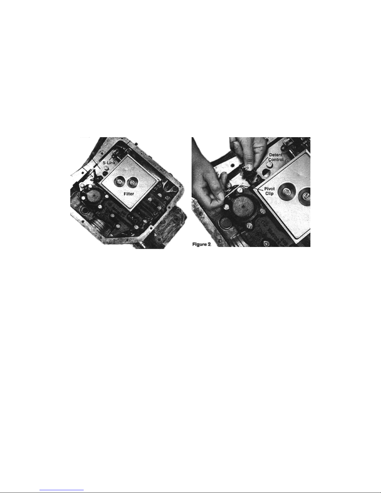
STEP 2 Use a screwdriver to remove two (2) screws and remove the oil filter and filter gasket.
Put them in the oil pan. (See Figure 1)
STEP 3 Observe the location of the following: (See Figure 1) Manual linkage, detent spring and
roller, s-link or offset link, detent control valve link and lever, and support plate.
STEP 4 Remove pivot clip holding detent control valve lever in place. (See Figure 2) Remove
lever also and set them in the tray. Remove eighteen (18) valve body attaching bolts. (See
Figure 3) Remove valve body by pulling straight down and disengaging manual valve and link
from manual lever. (Do not let manual valve fall out of valve body.) Put the valve body in the oil
pan and replace with new TCI
®
manual/automatic valve body.
Figure 1
STEP 5 Remove support plate bolts and support plate. (See Figure 3) Remove separator plate,
gasket and four (4) check balls. Check balls are located between the plate and the case.
STEP 6 Vacuum Modulator: No modification is necessary for this application. Part throttle shift
points can be lowered 5-6 mph by installing the gold spring in back of the modulator valve.
Remove modulator and valve. (See Figure 7) Insert spring on end of valve and install valve and
modulator as removed. Reconnect vacuum line. Adjustable modulator should be used with this
valve body kit. You can purchase this from TCI
®
or any GM dealer.
Figure 2
Page 3
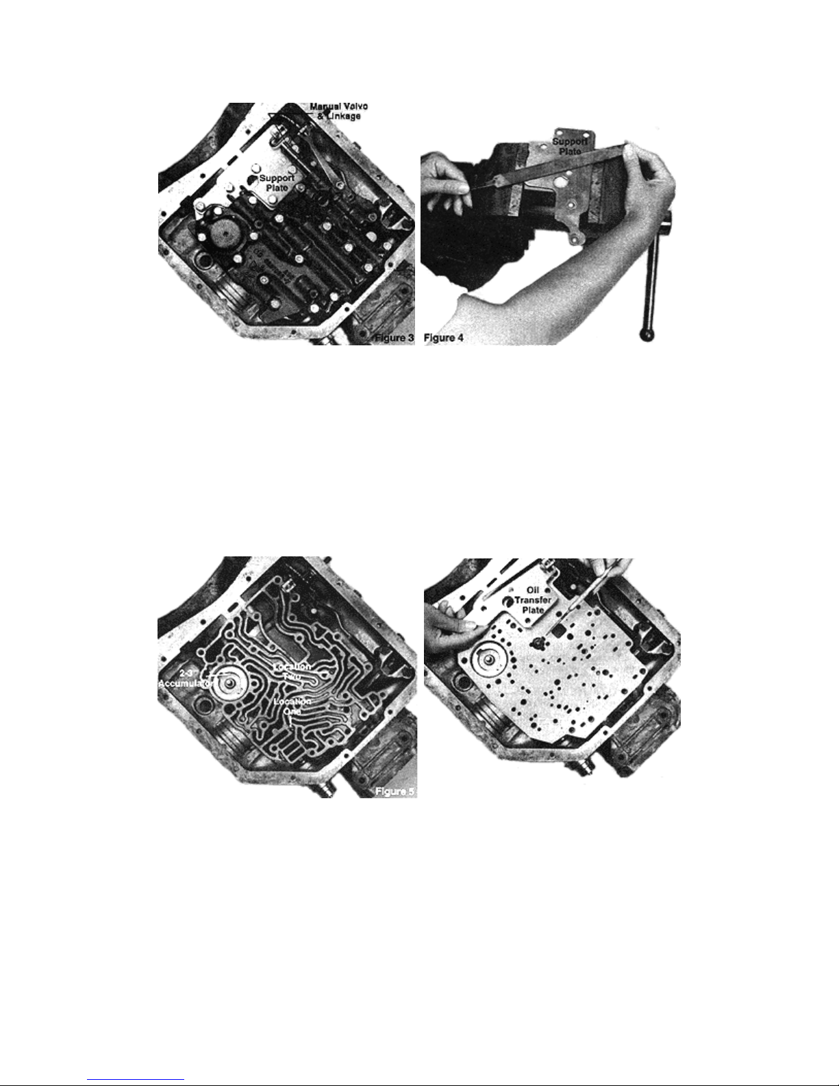
STEP 7 Clamp the support plate in a vise and run a file across the surface that will contact the
separator plate. (See Figure 4) You want the support to be flat. If your stiffener plate is bent or
excessively warped, it should be replaced.
STEP 8 Scrape any excess gasket material that may be stuck to the case surface. Thi s is very
important as stray gasket can cause leaks.
STEP 9 Lay separator plate-to-case gasket (the large one) in position on the separator plate.
Check Ball positioning: Two (2) check balls. One (1) in location 1 and one (1) in location 2. (See
Figure 5) Check balls may be held in place with grease or Vaseline.
Figue 5
STEP 10 Install special oil transfer plate and stock support plate (See Figure 6) Note: Slot in
transfer plate lines up with two holes in the separator plate and creates an new oil circuit.) Install
support plate bolts finger tight. Remove center pan bolt. Make sure plate does not drop far
enough to lose check balls.
Figure 6
Page 4
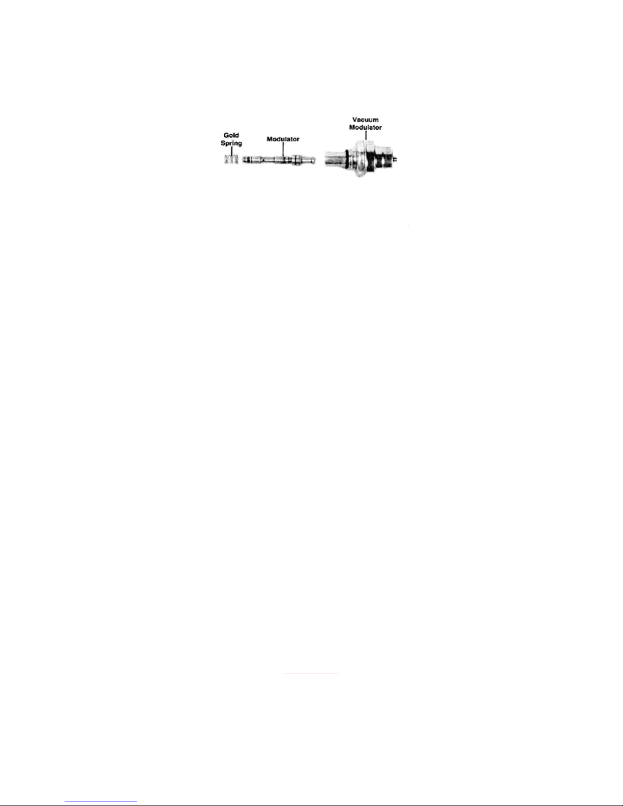
Figure 7
STEP 11 Lay valve body gasket (the small one) on the valve body. Guide valve body into
position. Engage manual valve linkage in selector lever. S-link can only install one way. Offset
linkage must be installed with the link in the forward position. Install valve body bolts finger tight.
Install detent roller spring so it engages selector lever. Tighten valve body bolts to 13-ft.Ibs.
Tighten stiffener plate bolts to 13-ft.lbs. Make sure shifter operates freely at this point.
STEP 12 Install new oil filter and gasket supplied. Tighten screws securely.
STEP 13 Clean pan in solvent and scrape any excess gasket material off of the pan and case
surface. Install pan with new gasket. Install pan bolts and tighten 13ft.-lbs. Tighten drain plug, if
so equipped. (Remember TCI
STEP 14 Check shifter adjustment. Place selector lever in each gear position making sure
detents in transmission correspond exactly with selector lever detents. Adjustments can be made
by loosening pinch bolt on rod or cable.
STEP 15 Detent cable: Depress accelerator pedal fully and check that throttle is opening fully.
Adjust if necessary. Adjust detent cable so that full throttle coincides with maximum cable
position. Detent cable must be connected to prevent transmission damage.
STEP 16 Lower vehicle. Keep the rear wheels of the ground if possible. Add four (4) quarts of
type "F’ ATF (GM Dexron3) or use TCl
friction, increase performance, and reduce heat. Place transmission in neutral, start engine and
fill to the "Add" marks. Place selector lever in all gear positions. If the wheels are off the ground,
allow the transmission to shift through all gears. Check fluid level and make sure it is between
"Add" and "Full".
STEP 17 Lower vehicle and drive 1-2 miles to warm fluid. Check level again. Do not overfill. This
can cause foaming and overheating.
®
805800 drain plug kit for easy fluid changes.)
®
’s RTF Part No. 950600 specially formulated to reduce
Back to Top
02/2000
 Loading...