

Page 1
Warnings and Cautions
OUTPUT
Warning
Warning
!
General Safety Instructions
Warning
Dangerous Voltage Warning: warns of
situations in which a high voltage can
cause injury and/or equipment damage.
e text next to this symbol describes
ways to avoid danger.
General Warning: warns of situations
that can cause physical injury and/
or equipment damage by means other
than electrical. e text next to this
symbol describes ways to avoid the
danger.
Be sure to read, understand, and follow
all safety instructions.
!
Warning
Only qualied electricians should
carry out all electrical installation and
!
Warning
!
Warning
Warning
maintenance work on reactors.
All wiring must be in accordance with
the National Electrical Code (NEC)
and/or any other codes that apply to
the installation site.
Disconnect all power before working
on the equipment. Do not attempt any
work on a powered reactor.
e reactor, VFD, motor, and other
connected equipment must be properly
grounded.
When installing the KLR/KDR Reactors
on the OUTPUT side of the Variable
Frequency Drive (VFD), please use the
following guidelines:
TCI recommends 1.5% impedance
reactors to be used on the output of the
VFD. In case of the KDR line, use only the
KDR OUTPUT reactors
Reactors should be mounted as
close to the output terminals of the VFD as
possible
TCI suggests that the reactor be
used in applications where the motor lead
length is less than 100 feet. For applications
with motor lead lengths greater than 100
feet, TCI oers V1k/KLC Output Filters
and KMG MotorGuard High Performance
Sinewave Filters.
Reactors are sized by the Full Load
Amps located on the motor nameplate.
Please contact TCI Technical Support
or your TCI distributor for application
information regarding the use of these
reactors on the load or output side of the
VFD or in applications where inductors are
used.
Reactor
Installation
Guide
Warning
All electrical connections must be re-torqued
annually.
e VFD terminals and connected
cables are at a dangerously high voltage
when power is applied to the VFD,
regardless of motor operation.
TCI, LLC
W132 N10611 Grant Drive
Germantown, WI 53022
Ph: 800-TCI-8282
www.transcoil.com
TCI, LLC
W132 N10611 Grant Drive
Germantown, WI 53022
Ph: 800-TCI-8282
www.transcoil.com
Revision 3.4 Part # 24774 Mar. 29, 2011
Page 2
KLR/KDR Line Reactor
Installation Instruction
INPUT
TCI recommends that these reactors
be wired and located as close to the front
end of the VFD as possible to have the
greatest success in both protecting the VFD
as well as mitigating line harmonics.
Field Wiring Information
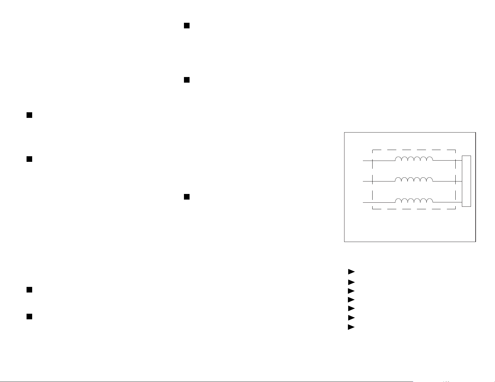
Below is the typical wiring diagram for the
3-phase reactor applied to the front end of
the Variable Frequency Drive (VFD).
When installing the KLR/KDR Line Reactors
on the INPUT side of the Variable Frequency
Drive (VFD), please use the following
guidelines when wiring the unit:
e KLR/KDR Line Reactor is a
3-phase device and should be wired in a
series and positioned on the input side of the
VFD.
All Terminal Block connectors will
be marked. A1, B1, and C1 are the input
terminals where the 3 phases of incoming
power are to be wired. As a result, A2, B2,
and C2 are the output terminals. Units with
copper bus or ring lug terminals are not
marked. In these cases, either the upper
terminals or lower terminals can be used as
the input terminals as long as the selection is
consistent. For example, if an upper terminal
is selected as the input, all upper terminals
must be input terminals. Wiring from the
output terminals should connect to the input
of the VFD.
Refer to NEC wiring practices for
appropriate wire sizes for your application.
Power Wiring: Only use 75°C copper
conductors unless the wire connector is
marked for Al/Cu, then the use of aluminum
wire is permitted.
In standard 40°C ambient or less
installations, a clearance of 3 inches on
all sides of the reactors and its enclosure
is recommended for assisting in heat
dissipation and ample wire bending space.
is is a general guideline for typical
applications. If the reactor is being installed
next to a heat sensitive instrument or
control device, we recommend reviewing
specic requirements or heat limitations.
Line reactor heat loss information is
available on the web at www.transcoil.com.
ese reactors are designed to be
oor-mounted or wall-mounted. Large
open-style devices should be panel
mounted by incorporating a bracket that
would act as a shelf to support the reactor
and/or enclosure. When installing an open
style device in an existing control cabinet,
drive cabinet, motor control center, or
other large enclosure, the reactor should be
mounted in the lower half of the cabinet to
prevent hot spots or pockets of heat (this
typically allows better thermal dissipation
and heat convection). Reactors with ducts
must be mounted in such a way that
maximizes air ow. Reactors with ducts
are designed to be mounted vertically for
proper cooling.
Single-phase applications are acceptable,
however, it is important to size the unit
based on the single phase Full Load
Amperage of the VFD. e input and
output connections should be on terminals
A and C to ensure proper performance.
Wiring Diagram
A1
L1
LINE
B1*
L2
C1
L3
LINE REACTOR
* For single-phase applications, use coils A and C.
Isolate terminals B1 and B2.
A2
LOAD
B2*
C2
Product Specications
3-Phase, 600 Volt Class
UL Recognized; File E-116124
CE Marked
CSA Certied
Current-rated device
200% rated current for 3 minutes
Ambient Temperature: 40°C
 Loading...