

Page 1

MotorGuard
KMG High Performance
Output Sine Wave Filter
Installation, Operation, and Maintenance Manual
Page 2

MotorGuard
™
KMG High Performance Output Sinewave Filter
Installation, Operation, and Maintenance Manual
TCI, LLC
W132 N10611 Grant Drive
Germantown, Wisconsin 53022
Phone: 414-357-4480
Fax: 414-357-4484
Helpline: 800-TCI-8282
Web Site: http://www.transcoi l. c om
© 2014
iv
Page 3

T able of Contents
Safety Instructions ........................................................................................ 5
Overview ................................................................................................................................................. 5
Warnings and Cautions ......................................................................................................................... 5
General Safety Instructions .................................................................................................................. 6
Introduction .................................................................................................... 7
Intended Audience ................................................................................................................................. 7
Additional Information ......................................................................................................................... 7
Installation Checklist ............................................................................................................................. 7
Receiving Inspection and Storage ............................................................... 8
Receiving Inspection .............................................................................................................................. 8
Warranty Information .......................................................................................................................... 8
Storage Instructions ............................................................................................................................... 8
Product Description ...................................................................................... 9
MotorGuard Sine Wave Filter .............................................................................................................. 9
Nameplate Data .................................................................................................................................... 10
Model Number Encoding .................................................................................................................... 11
Standard Product Ratings and Dimension Tables ............................................................................ 12
Product Technical Specifications........................................................................................................ 17
Pre-installation Planning ............................................................................. 19
Verify the Application ......................................................................................................................... 19
Select a Suitable Location ................................................................................................................... 19
Power Wiring ....................................................................................................................................... 20
Control Wiring (for units with boards).............................................................................................. 20
Optional Features ................................................................................................................................ 20
Installation Guidelines ................................................................................ 21
Mounting .............................................................................................................................................. 21
Wiring ................................................................................................................................................... 21
MotorGuard Operation ................................................................................ 24
Adjustments ......................................................................................................................................... 24
3
Page 4

Start Up (Commissioning) ................................................................................................................... 24
Operation .............................................................................................................................................. 24
Maintenance and Service ........................................................................... 25
MotorGuard Reliability and Service Life .......................................................................................... 25
Periodic Maintenance........................................................................................................................... 25
For Units with Boards:......................................................................................................................... 25
Troubleshooting .................................................................................................................................... 26
Replacement Parts ................................................................................................................................ 29
Factory Contacts and Tech Support ................................................................................................... 29
Drawings ...................................................................................................... 30
Typical Isometr i c Drawings and Schematic Diagrams ..................................................................... 30
4
Page 5
Safety Instructions
!
Overview
This section provides the safet y instructions which must b e followed when installing, operating and
servicing t he KMG MotorGuard Filter. If neglected, physical injury or death may follow, or damage
may occur to the MotorGuard or equipment connected to the MotorGuard. The material in this chapter
must be read and understood before attempting any work on, or with, the product.
The MotorGuard is intended to be connected to the output terminals of a variable frequency drive
(VFD). An AC motor is connected to the output terminals of the MotorGuard and receives power from
the VFD through the MotorGuard. The instructions, and particularly the safet y instructions, for the
VFD, motor and any other related equipment must be read, understood and followed when working on
any of the equipment.
Warnings and Cautions
This manual provides two types of safety instructions.
Warnings caution readers about conditions, which can, if proper steps are not taken, lead to a serious
fault condition, physical injury, or death.
Cautions are used to draw attention to instructions. Failure to properly follow such instr uctions may
lead to a malfunction and possible equipment damage.
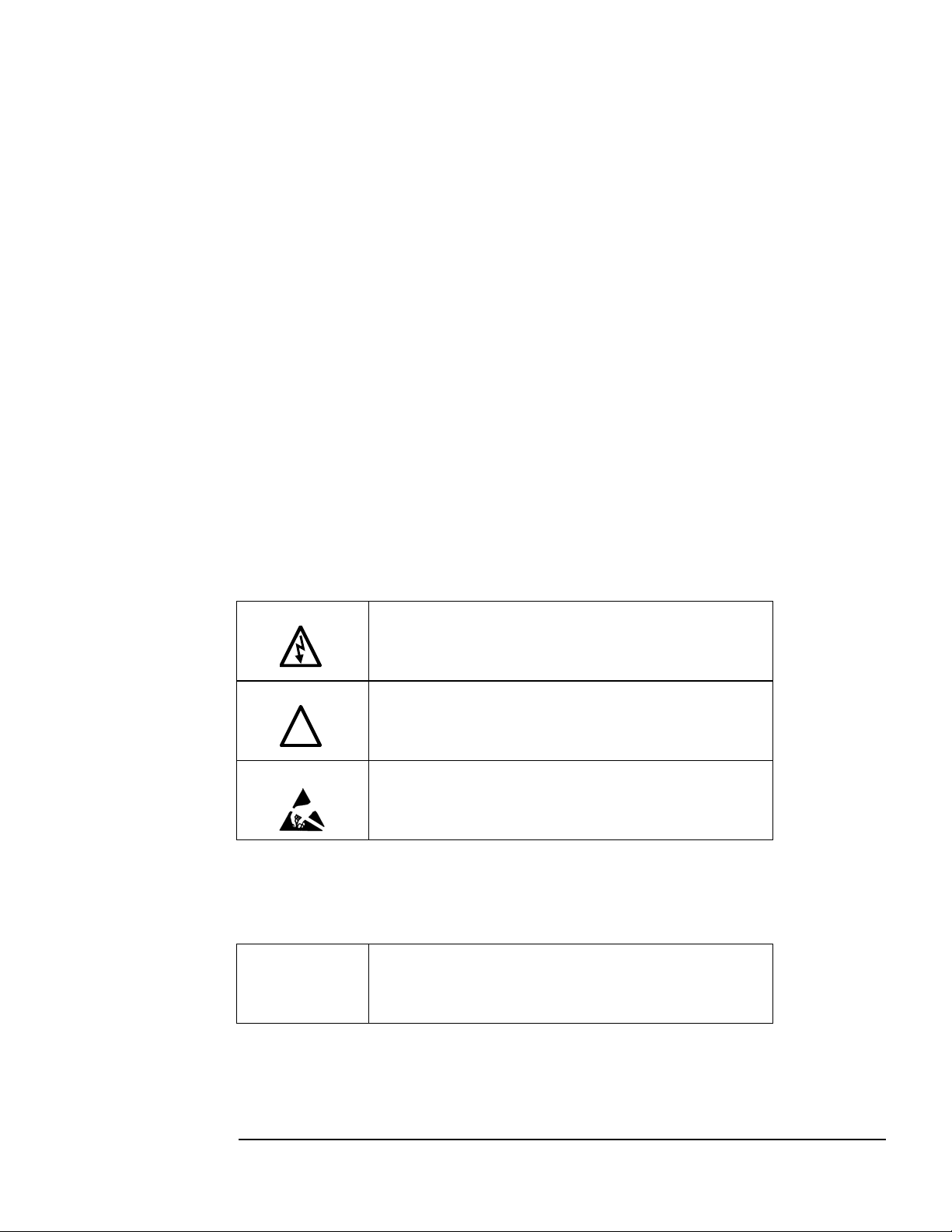
Warnings
Readers are informed of situations that can result in serious physical injury and/or serious damage to
equipment wit h war ni n g stat e men t s mar ked wit h the fo ll o wi ng s ymb o ls:
Warning
Warning
Warning
Dangerous Voltage Wa rning: warns of situations in which a
high voltage can cause physical injury and/or equipment
damage. The text next to this symbo l describes ways to avoid
the danger.
General Warning: warns of situations that can cause physical
injury and/ or equipment damage by means other than
electrical. The text next to this symbol describes ways to avoid
the danger.
Electrostatic Discharge Warning: warns of situations i n which
an electrostatic discharge may damage equipment. The text
next to this symbol desc ribes ways to avoid the d anger.
Cautions
Readers are informed of situations that can lead to a malfunction and possible equipment damage with
caution statements:
Caution
General Caution: identifies situatio ns that can lead to a
malfunction and possible equipment damage. The text
describes ways to avoid the situatio n.
5
Page 6
General S afety Ins truct ions
torGuard for the cooling
urces of power have been disconnected
!
!
!
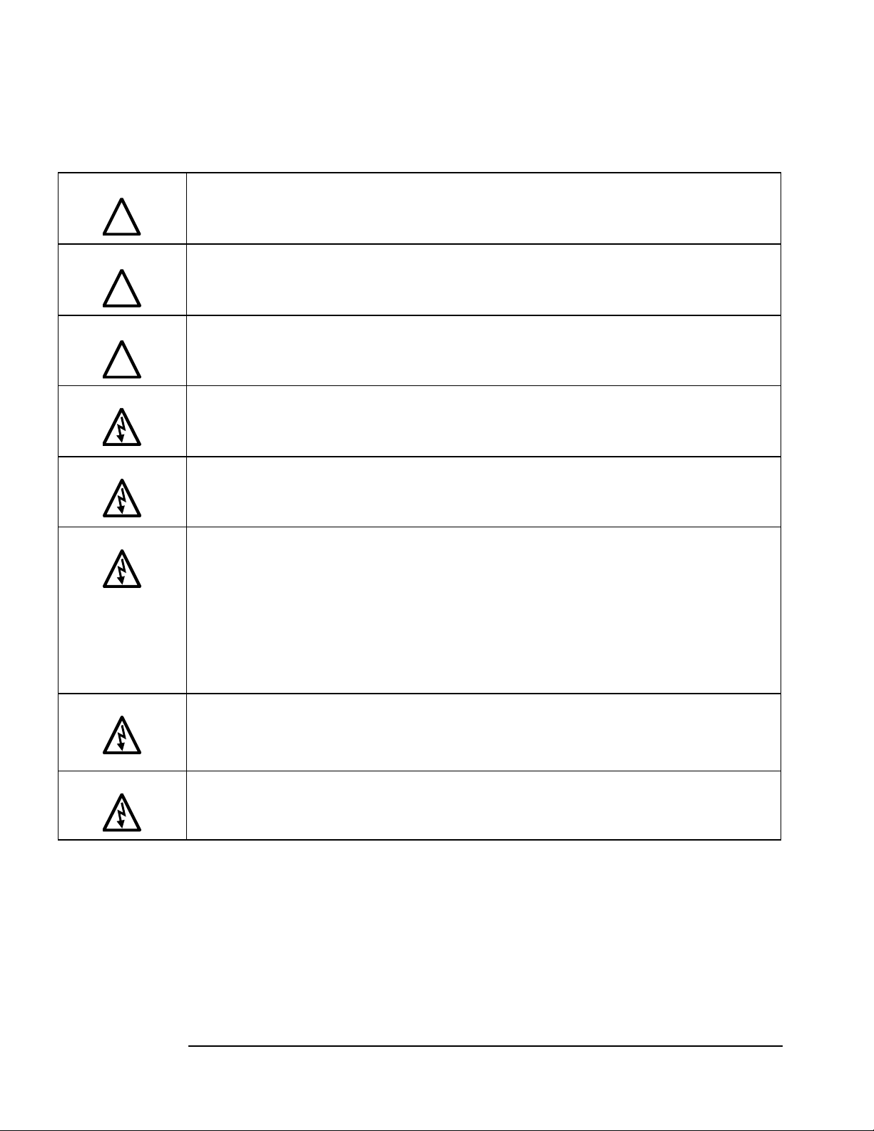
These safety instructions are intended for all work on the MotorGuard. Additional safety instructions
are provided at appropriate points o n other sec tions of this manual.
Warning
Warning
Warning
Warning
Warning
Warning
Be sure to read, understand, and follow all safety instructions.
Only qualified electricians should carry out all electrical installation and maintenance work on the
MotorGuard.
All wiring must be in accordance with the National Electrical Code (NEC) and/or any other codes that
apply to the installation site.
Disconnect all power before working on the equipment.
Do not attempt any work on a powered MotorGuard.
The MotorGuard, VFD, motor, and other connected equipment must be properly grounded.
The MotorGuard receives power from two or more sources.
Three-phase power from the output terminals of the VFD is c onnected to the main input terminals of
the MotorGuard.
Power from a single-phase 120, 240 or 480 volt supply is connected to the Mo
fan and monitor board.
The monitor board alarm contacts may be connected to a circuit that receives power from another
source.
All of these sources of power must be disconnected before working on the MotorGuard.
Warning
Warning
After switching off the power, always allow 5 minutes for the capacitors in the MotorGuard and in the
VFD to discharge before working on the MotorGuard, the VFD, the motor, or connecting wiring. It is
good practice to check with a voltmeter to make sure that all so
and that all capacitors have discharged before beginning work.
The VFD output terminals and the motor cables are at a dangerously high voltage when power is
applied to the VFD regardless of motor operation.
6
Page 7

Introduction
Caution
Select a mounting area that will allow adequate cooling air and maintenance access.
Make sure that all wiring conforms to the requirements of the National Electric Code (NEC)
Connect the MotorGuard equipment grounding lug to the system ground of the premises wiring
Wire the output power terminals, of the MotorGuard, T1, T2, & T3 to the motor.
Connect control power to the MotorGuard.
For monitor board option: Connect the MotorGuard fault relay contact to the appropriate fault
Make sure that the VFD is set for operating modes and ranges that are compatible with the
Thank you for se lec ti n g t he KMG MotorGuard High Performa nce O utput Filter. TCI has p rod uced this
filter for use in many PWM variable frequency drive (VF D) applications that require low distortion
sine wave o utput po wer. This manual de scribes how to i nstall, operate, and maintain the MotorGuard
filter.
Intended Audience
This manual is intended for use by all personnel responsible for the installation, operation, and
maintenance of the MotorGuard. Such personnel are expected to have knowledge of electrical wiring
practices, electronic components, and electrical schematic symbols.
Additiona l Infor mation
This manual provides general information describing your MotorGuard filter. More specific
information is provided by the drawings shipped with the unit. Be s ure to carefully review t he
information provided by these drawings. Information provided by the drawings shipped with the unit
takes precedence over the information provided in this manual.
Installation Checklist
The following are the key points to be followed for a successful installation. These points are
explained in detail in the following sections of this manual.
Make sure that the installation lo c a tion will not be exposed to direc t sunlight, c orrosive or
combustible airborne contaminants, excessive dirt, or liquids.
and/or other applicable electrical codes.
system. Use a properly sized grounding conductor.
Wire the output power termina ls o f the V FD, T1(U), T2(V), & T3(W) to the input terminals of
the MotorGuard, U, V, & W.
monitoring c ircuit.
Check the MotorGuard configuration settings to ensure proper voltage is selected.
MotorGuard.
Check ever ything thor oughly be fore operating the equipment.
7
Page 8

Receivi ng Inspection and Storage
Receiving Inspection
The MotorGuard has been thoroughly inspected and functionally tested at the factory and carefully
packaged for shipment.
When you receive the unit, you should immediately inspect the shipping container and report any
damage to the carrier that delivered the unit.
Verify that the part number of the unit you received is the same as the part number listed on your
purchase order.
Warranty Info rmatio n
TCI, LLC (“TCI”) warrants to the original purchaser only that MotorGuard products will be free from
defects in materials and workmanship under normal use and service for a period originating on the date
of shipment from TCI and expiring at the end of One (1) year of useful service, not to exceed 18
months from the date of shipment. The foregoing limited warranty is TCI’s sole warranty with respect
to its products and TCI makes no other warranty, representation or promise as to the quality or
performance of TCI’s products. THIS EXPRESS LIMITED WARRANTY IS GIVEN IN LIEU OF
AND EXCLUDES ANY AND ALL EXPRESS OR IMPLIED WARRANTIES INCLUDING,
WITHOUT LIMITATION, ANY IMPLIED WARRANTY OF MERCHANTABILITY OR FIT NESS
FOR A PARTICULAR PURPOSE.
This warranty shall not apply if the product was:
a) altered or repaired by anyone other than TCI;
b) applied or used for situations other than those originally specified; or
c) subjected to negligence, accident, or damage by circumstances beyond TCI’s control, including
but not limited to, improper stor a ge, installation, operation or maintenance.
If, within the warranty period, any product shall be found in TCI’s reasonable judgment to be
defective, TCI’s liability and the Buyer’s exclusive remedy under this warranty is expressly limited, at
TCI’s option, to (i) repair or replace ment of that product, or (ii) return of the product and refund of the
purchase price.
Such remedy shall be Buyer’s sole and exclusive remedy. TCI SHALL NOT, IN ANY EVENT, BE
LIABLE FOR INCIDENTAL DAMAGES OR FOR CONSEQUENT IAL DAMAGES INCLUDING,
BUT NOT LIMITED TO, LOSS OF INCOME, LOSS OF TIME, LOST SALES, INJURY TO
PERSONAL PROPERTY, LIABILITY BUYER INCURS WITH RESPECT TO ANY OTHER
PERSON, LOSS OF USE OF THE PRODUCT OR FOR ANY OTHER TYPE OR FORM OF
CONSEQUENTIAL DAMAGE OR ECONOMIC LOSS.
The foregoing warranties do not cover reimbursement for removal, transportation, reinstallation, or any
other expenses that may be incurred in connection with the repair or replacement of the TCI product.
The employees and sales agents of TCI are not authorized to make additional warranties about TCI ’s
products. TCI’s employees and sales agents oral statements do not c onstitute warranties, shall not be
relied upon by the Buyer and are not part of any contract for sale. All warranties of TCI embodied in
this writing and no other warranties are given beyond those set forth here in.
TCI will not accept the return of any product witho ut its prior written approval. Please consult TCI
Customer Service for instructions on the Ret urn Authori zation Pr ocedure.
Storage Instructions
If the MotorGuard is to be stored before use, be sure that it is stored in a location that conforms to
published storage humidit y and temperature specifications stated in this manual. Store the unit i n its
original packaging.
8
Page 9

Product Descript ion
MotorGuard Sine Wave Filter
The MotorGuard is a low-pass sine wave filter designed and developed by TCI to deliver conditioned
power to motor loads driven by PWM drives at a variety of lead lengths. The MotorGuard is available
for 460/480 volt and 575/600 volt systems.
The MotorGuard is a passive filter connected in series with the output terminals of the variable
frequency drive. It is designed to remove the carrier frequency distortion from the output voltage
waveform. The use of this low-pass, L-R-C device will result in a nearly pure sine wave voltage
profile. This design will reduce the effects of the reflected wave phenomenon, (dv/dt), such as
insulation damage or premature failure in motors, transformers and VFD output cables. The
MotorGuard will also reduce the effects of stray high fre quency harmo nic current s, thereby red ucing
VFD ground fault prob l ems and noise interference in transducer signals.
The MotorGuard is available in t wo package configuration s: Industrial and GP. The Industrial filter is
a stand-alone device that can be furnis hed in it s o wn enclo sure a nd mo unted a dja cent to the VFD, and
is also avai lable on an op en panel for mo unting withi n an enclosure p rovided with t he VFD or othe r
equipment. The GP filter is furnished in its own enclosure and mounted adja c e nt to the VFD.
The MotorGuard is suitable for all lead lengths extending as far as 15,000 feet.
The MotorGuard consists of the following standard features and components:
♦ An R-L-C power filter circuit with:
A TCI 3-phase reactor specifically designed for the MotorGuard
Power resistors
High-endurance, harmonic-rated capacitors
♦ Bleeder resistors to ensure safe capacitor discharge upon filter shutdown.
♦ Compression terminals for ease and integrity of all power wiring.
♦ Cooling fans to ensure adequate cooling and safe operating temperatures.
Optional Monitor Board is available:
♦ A filter performance monitor and alarm circuit with:
Monitor board with relay and status indica ting lights
Control transformer for control voltage power
Compression terminal blocks for all control wiring
9
Page 10
Nameplate Data
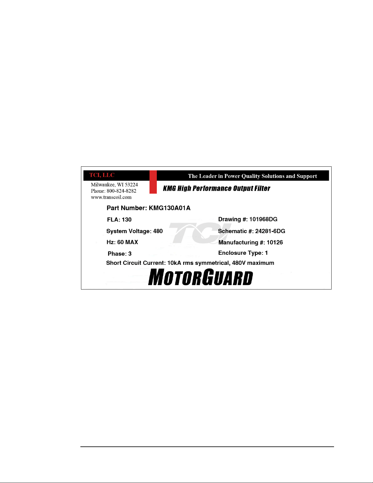
Figure 1 sho ws an example of a MotorGuard na meplate. The following i nformation is marked on the
nameplate:
♦ Part number: encoded model number explained on the following page
♦ FLA: the rated continuous ope rating current (RMS amps)
♦ System Voltage: the maximum VFD output voltage (fundamental)
♦ Hz: the maximum VFD output frequency (fundamental)
♦ Phase: 3 – The MotorGuard is designed for use only with 3 phase motors.
♦ Drawing #: outline and mounting dimension of filter
♦ Schematic #: schematic diagram of filter
♦ Manufacturing #: for TCI internal use
♦ Enclosure Type: Industrial filters are open panel construction or NEMA 1 enclosed. GP filters
are NEMA 1 or NEMA 3R enclosed.
Figure 1 – Example of MotorGuard Nameplate
10
Page 11
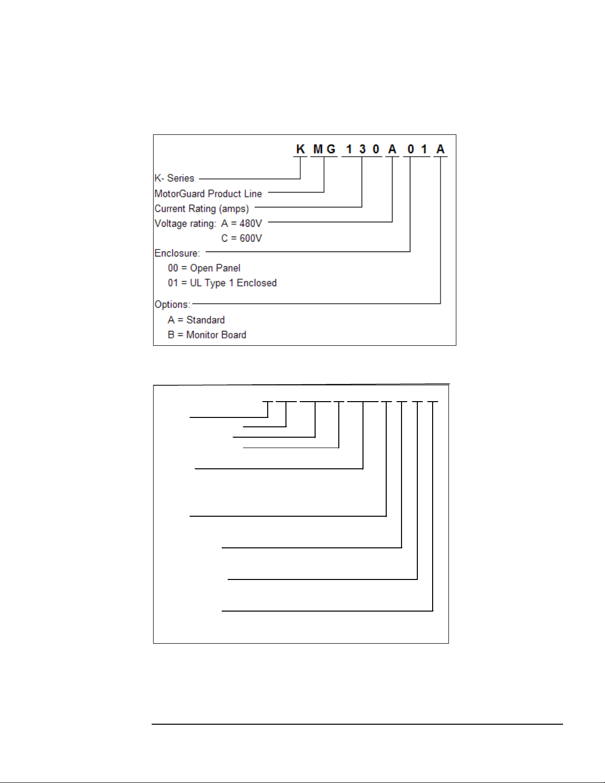
Model Number Enc oding
H = Space Heater
0 = No Thermal Switch
Monitor Board
B = Monitor Board
0 = No Monitor Board
Thermal Switch
L = Lugs
C = 600V
Voltage rating:
K
0 = No Space Heater
Space Heater
0 = No Lugs
S = Thermal Switch
Lugs
0
0
Options:
Enclosure:
Current Rating (amps)
A = 480V
K- Series
MotorGuard Product Line
0100A0G
G01 = General Purpose Indoor (gray)
G3R = General Purpose NEMA 3R (white)
MG3
1
Figures 2a and 2b identify the significance of each character in the MotorGuard model number. The
example model number, KMG130A01A designate s an Industrial MotorGuard that is rated 130 amps,
480 volts, and is furnished in a NEMA 1 enclosure.
Figure 2a – MotorGuard Model Number Encodi ng – Industrial V ersion
Figure 2b – MotorGuard Model Number Encoding – General Purpose Version
The MotorGuard has a current rating rather than a horsepower rating. The rating and dimension tables
in the following section list the nominal horsepo wer ratings corr esponding to the current ratings of the
standard models.
11
Page 12

Standard Product Ratings and Dimension Tables
The following tables list the ratings and dimensions of the standard MotorGuard models:
♦ Table 1 lists 480 Volt models on open panels.
♦ Table 2 lists 480 Volt models in NEMA 1 enclosures.
♦ Table 3 lists 600 Volt models on open panels.
♦ Table 4 lists 600 Volt models in NEMA 1 enclosures.
♦ Table 5 lists 480 Volt models in NEMA 1 enclosures.
♦ Table 6 lists 480 Volt models in NEMA 3R enclosures.
♦ Table 7 lists 600 Volt models in NEMA 1 enclosures.
♦ Table 8 lists 600 Vo lt models in NEMA 3R enclosures.
12
Page 13
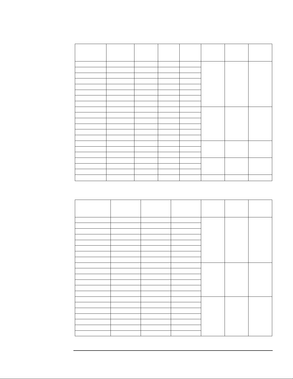
Table 1 – Industrial 4 80 Volt Models on Ope n Pane ls
KMG8A00A
5 8 300
60
KMG12A00A
7.5
12
350
60
KMG16A00A
10
16
400
70
KMG23A00A
15
23
550
75
KMG30A00A
20
30
650
85
KMG35A00A
25
35
750
85
KMG45A00A
30
45
850
100
KMG55A00A
40
55
1000
115
KMG65A00A
50
65
1100
160
KMG80A00A
60
80
1550
175
KMG110A00A
75
110
1700
195
KMG130A00A
100
130
2050
200
KMG160A00A
125
160
2450
250
KMG200A00A
150
200
3300
255
KMG250A00A
200
250
3700
445
KMG305A00A
250
305
4700
460
KMG362A00A
300
362
4650
475
KMG420A00A
350
420
5400
580
KMG480A00A
400
480
6050
635
KMG600A00A
500
600
7350
645
KMG750A00A
600
750
8800
760
60.00
32.00
17.75
(amps)
KMG8A01A
5 8 110
KMG12A01A
7.5
12
110
KMG16A01A
10
16
120
KMG23A01A
15
23
125
KMG30A01A
20
30
140
KMG35A01A
25
35
140
KMG45A01A
30
45
155
KMG55A01A
40
55
170
KMG65A01A
50
65
245
KMG80A01A
60
80
260
KMG110A01A
75
110
280
KMG130A01A
100
130
300
KMG160A01A
125
160
340
KMG200A01A
150
200
345
KMG250A01A
200
250
770
KMG305A01A
250
305
790
KMG362A01A
300
362
800
KMG420A01A
350
420
915
KMG480A01A
400
480
970
KMG600A01A
500
600
975
KMG750A01A
600
750
1085
Model
Number
Nominal
Horspower
Current
Rating
(amps)
Heat
Loss
(Watts)
Weight
(lbs.)
Height
(in.)
30.75 17.00 11.75
56.00 17.00 11.75
60.00 32.00 14.75
60.00 32.00 16.38
Width
(in.)
Depth
(in.)
Table 2 – Industrial 480 Volt Models in NEMA 1 Enclosures
Model
Number
Nominal
Horspower
Current
Rating
Weight
(lbs.)
Height
(in.)
31.38
Wall
Mounted
56.00
Wall
Mounted
76.50
Free
Standing
Width
(in.)
17.50 12.14
17.52 16.40
36.00 24.00
Depth
(in.)
13
Page 14
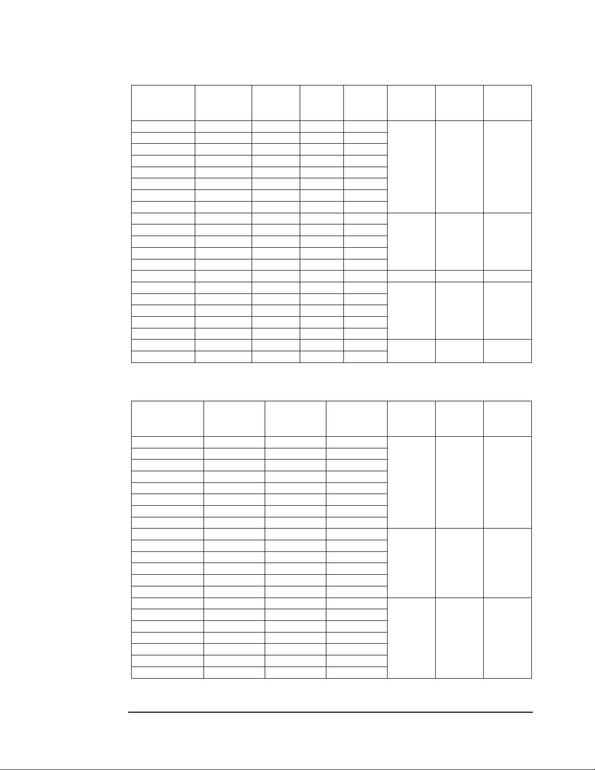
Table 3 – Industrial 6 00 Volt Models on Ope n Pane ls
KMG8C00A
5 8 400
60
KMG10C00A
7.5
10
400
65
KMG12C00A
10
12
400
70
KMG20C00A
15
20
550
75
KMG25C00A
20
25
700
85
KMG28C00A
25
28
750
90
KMG35C00A
30
35
800
100
KMG45C00A
40
45
950
115
KMG55C00A
50
55
1200
160
KMG65C00A
60
65
1600
175
KMG80C00A
75
80
1650
195
KMG110C00A
100
110
2250
225
KMG130C00A
125
130
2300
250
KMG160C00A
150
160
2500
260
56.00
17.00
14.78
KMG200C00A
200
200
3500
450
KMG250C00A
250
250
4500
460
KMG305C00A
300
305
5100
475
KMG362C00A
350
362
6100
580
KMG420C00A
400
420
6900
635
KMG500C00A
500
500
7900
645
KMG600C00A
600
600
9000
750
KMG8C01A
5 8 115
KMG10C01A
7.5
10
115
KMG12C01A
10
12
120
KMG20C01A
15
20
135
KMG25C01A
20
25
140
KMG28C01A
25
28
145
KMG35C01A
30
35
155
KMG45C01A
40
45
175
KMG55C01A
50
55
260
KMG65C01A
60
65
265
KMG80C01A
75
80
265
KMG110C01A
100
110
290
KMG130C01A
125
130
295
KMG160C01A
150
160
340
KMG200C01A
200
200
770
KMG250C01A
250
250
775
KMG305C01A
300
305
790
KMG362C01A
350
362
975
KMG420C01A
400
420
975
KMG500C01A
500
500
1015
KMG600C01A
600
600
1015
Model
Number
Nominal
Horspower
Current
Rating
(Amps)
Heat
Loss
(Watts)
Weight
(lbs.)
Height
(in.)
30.75 17.00 11.75
56.00 17.00 11.75
60.00 32.00 14.75
60.00 32.00 16.00
Width
(in.)
Depth
(in.)
Table 4 – Industrial 600 Volt Models in NEMA 1 Enclosures
Model
Number
Nominal
Horspower
Current
Rating
(Amps)
Weight
(lbs.)
Height
(in.)
31.38
Wall
Mounted
56.00
Wall
Mounted
76.50
Free
Standing
Width
(in.)
17.50 12.14
17.52 16.40
36.00 24.00
Depth
(in.)
14
Page 15
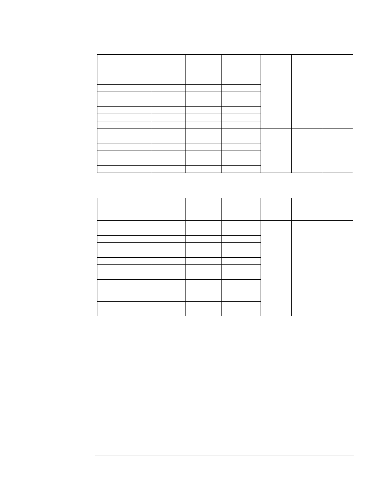
Table 5 – General Purpose 480 Volt Models in NEMA 1 Enclosures
KMG55AG010000
40
55
209
KMG65AG010000
50
65
215
KMG80AG010000
60
80
235
KMG110AG010000
75
110
220
KMG130AG010000
100
130
225
KMG160AG010000
125
160
250
KMG200AG010000
150
200
260
KMG250AG010000
200
250
595
KMG305AG010000
250
305
625
KMG362AG010000
300
362
630
KMG420AG010000
350
420
635
KMG480AG010000
400
480
635
KMG600AG010000
500
600
755
KMG55AG3R0000
40
55
209
KMG65AG3R0000
50
65
215
KMG80AG3R0000
60
80
235
KMG110AG3R0000
75
110
220
KMG130AG3R0000
100
130
225
KMG160AG3R0000
125
160
250
KMG200AG3R0000
150
200
260
KMG250AG3R0000
200
250
595
KMG305AG3R0000
250
305
625
KMG362AG3R0000
300
362
630
KMG420AG3R0000
350
420
635
KMG480AG3R0000
400
480
635
KMG600AG3R0000
500
600
755
Model
Number
Nominal
Horspower
Current
Rating
(Amps)
Weight
(lbs.)
Height
(in.)
36.50 18.67 29.50
64.00
Table 6 – General Purpose 480 Volt Models in NEMA 3R Enclosures
Model
Number
Nominal
Horspower
Current
Rating
(Amps)
Weight
(lbs.)
Height
(in.)
Width
(in.)
24.17
Width
(in.)
Depth
(in.)
42.00
Depth
(in.)
Hotel
36.50 18.67 29.50
64.00
24.17
42.00
15
Page 16

Table 7 – General Purpose 600 Volt Models in NEMA 1 Enclosures
KMG45CG010000
40
45
209
KMG55CG010000
50
55
235
KMG65CG010000
60
65
235
KMG80CG010000
75
80
266
KMG110CG010000
100
110
275
KMG130CG010000
125
130
280
KMG160CG010000
150
160
290
KMG200CG010000
200
200
570
KMG250CG010000
250
250
615
KMG305CG010000
300
305
620
KMG362CG010000
350
362
650
KMG420CG010000
400
420
675
KMG500CG010000
500
500
810
KMG600CG010000
600
600
(Amps)
KMG45CG3R0000
40
45
209
KMG55CG3R0000
50
55
235
KMG65CG3R0000
60
65
235
KMG80CG3R0000
75
80
266
KMG110CG3R0000
100
110
275
KMG130CG3R0000
125
130
280
KMG160CG3R0000
150
160
290
KMG200CG3R0000
200
200
570
KMG250CG3R0000
250
250
615
KMG305CG3R0000
300
305
620
KMG362CG3R0000
350
362
650
KMG420CG3R0000
400
420
675
KMG500CG3R0000
500
500
810
KMG600CG3R0000
600
600
Model
Number
Nominal
Horspower
Current
Rating
(Amps)
Weight
(lbs.)
Height
(in.)
36.50 18.67 29.50
64.00
Width
(in.)
24.17
Depth
(in.)
42.00
Table 8 – General Purpose 600 Volt Models in NEMA 3R Enclosures
Model
Number
Nominal
Horspower
Current
Rating
Weight
(lbs.)
Height
(in.)
Width
(in.)
Depth
(in.)
36.50 18.67 29.50
64.00
24.17
42.00
16
Page 17

Product Technical Specifications
Tables 9a, 9b, 10a, and 10b list the major technical specifications for the MotorGuard product line.
Table 9a – MotorGuar d Technical Spec ifications – Industrial
Current ratings Continuous current: 8 to 750 amps. See Rating and Dimension tables
Intermittent current: 150% for 1 minute out of every 60 minutes
VFD Drive output voltage 460/480 and 575/600 V, 3 ph, at fundamental base frequency
VFD Drive output
frequency
VFD Drive carrier
frequency
Control power input For fan operation.
Filter performance Maximum peak voltage of output waveform – 480 V models: 1000 V
Maximum elevation 3,000 feet (1,000 meters) as standard. Product must be equipped with
Maximum ambient
operating temperature
Maximum ambient storage
temperature
Maximum humi d it y,
operating or storage
Enclosure options Open panel for mounting in an enclosure furnished by others
Enclosure fi nis h Free standing enclosures: ANSI 61 gray
Agency approvals or
certifications
0 to 80 Hz
2 kHz and 12 kHz, ideally 4 kHz to 8 kHz
– 600 V models: 1500 V
Maximum dv/dt of output waveform – 480 V models: 500 V/μs
– 600 V models: 1500 V/μs
special cooling provisions for operation above this level
40 °C (104 °F) as standard. Product must be equipped with special
cooling provisions for operation above this temperature.
50 °C (122 °F)
95%, non-condensing.
NEMA 1 enclosure
Wall mount enclosures: White M a tte (beige) Munsel 5.8Y7.83/1
UL and cUL Listed to UL508A and CSA-C22.2 No. 14
Insertion impedance Approximately 6.5% at 60 Hz & full load current
Fusing and protection: Unit has internal fuse protection and a performance monitoring
circuit.
Capacitors Oil filled high endurance design (no PCBs)
Table 9b – Only with Board Option
Status indication LEDs Green LED indicates: "Control Power ON"
Yellow LED indicates: "Normal Operation" (not faulted)
Fault relay De-energized when a fault is detected.
Form C contact for customer use.
Rated 0.6 A at 125 VAC and 110 VDC, 2 A at 30 VDC.
17
Page 18

Table 10a – MotorGuard Technical Specifications – General Purpose
Current ratings Continuous current: 55 to 600 amps. See Rating and Dimension tables
Intermittent current: 150% for 1 minute out of every 60 minutes
VFD Drive output voltage 460/480 and 575/600 V, 3 ph, at fundamental base frequency
VFD Drive output
frequency
VFD Drive carrier
frequency
Control power input For fan operation.
Filter performance Maximum p eak voltage of output waveform – 480 V models: 1000 V
Maximum elevation 3,000 feet (1,000 meters) as standard. Product must be equipped with
Maximum ambient
operating temperature
Maximum ambient storage
temperature
Maximum humi d it y,
operating or storage
Enclosure options
Insertion impedance Approximately 6.5% at 60 Hz & full load current
Capacitors Oil filled high endurance desi gn (no PCBs)
0 to 80 Hz
2 kHz and 12 kHz, Ideally 4 kHz to 8 kHz
– 600 V models: 1500 V
Maximum dv/dt of output waveform – 480 V models: 500 V/μs
– 600 V models: 1500 V/μs
special cooling provisions for operation above this level
40 °C (104 °F) as standard. Product must be equipped with special
cooling provisions for operation above this temperature.
50 °C (122 °F)
95%, non-condensing.
General Purpose 3R enclosure
Table 10b – Only with Board Option
Status indication LEDs Green LED indicates: "Control Power ON"
Yellow LED indicates: "Normal Operation" (not faulted)
Fault relay De-energized when a fault is detected.
Form C contact for customer use.
Rated 0.6 A at 125 VAC and 110 VDC, 2 A at 30 VDC.
18
Page 19

Pre-installation Planning
!
Verify th e A pplicat ion
MotorGuard Ratings
Make sure that the MotorGuard is correct for the application. The voltage and current ratings of the
MotorGuar d must match the output voltage and current ratings of the connected variable frequency
drive as it is configured for use with the connected motor.
Variable Frequency Drive Settings
Make sure that the variable frequency drive will be set for operation modes and ranges that are
compatible with the MotorGuard:
♦ Maximum output frequency: 80 Hz
♦ PWM switching frequency between 2 kHz and 12 kHz, ideally 4 kHz to 8 kHz
♦ Mode of operation: "scalar" or "V/Hz" without DC brak ing unless the drive application has
been confirmed by TCI Technical Support
Select a Suitable Location
Environment
Locating the MotorGuard in a suitable environment will help ensure proper performance and a normal
operating life.
Warning
Unless specifically labeled as approved for such use, this equipment is not suitable for use in an
explosive atmosphere or in a "Hazardous (Classified) Location" as defined in article 500 of the
National Electrical Code.
The unit must be installed in a n ar e a where it will not be exposed to:
♦ Corrosi ve l i quids or gasses
♦ Explosive or combustible gases or dust
♦ Excessive airborne dirt and dust
♦ Excessive vibration
In addition to the above, products that are not in a 3R enclosure should not be exposed to:
♦ Direct sunlight
♦ Rain or excessive dripping liquids
Mounting Area
Select a mounting area that will allow sufficien t cooling air to flow through the unit. Adeq uate space
should be provided to allow access for maintenance.
Mounting an open panel unit
If you are mounting an open panel uni t in your own encl osure, you must p rovide a n enclo sure that is
adequately sized and ventilated sufficiently to pr e vent overheating. The rating and dimension tables for
open panel units list the watts of heat loss that is dissipated by the MotorGuard. The maximum
temperature of the air around the MotorGuard's capacitors and monitor board should not exceed 50 °C
(104 °F).
19
Page 20

Power Wiring
The conduit and wiring fr om the o utput o f the variab le freq uency d rive to the mo tor must be route d to
the MotorGuard and then to the motor. When selecting a mounting location for the MotorGuard, plan
for the routing of the power wiring.
Control Wiring (for u nits with boards)
Control Power
The MotorGuard requires 120 VAC single-phase power for the monitor board and cooling fan. The
control power source must be ensured to be energized whenever the variable frequency drive is
operating. A control power transformer is provided in the MotorGuard to allow control power to be
obtained from the three-phase source that provides input power to the VFD. Fuses are provided on the
control transformer, but the wires connecting control power to the MotorGuard will need to be
appropriately protected at the power source.
Control Power VA Requirement
Refer to the drawings furnished with your MotorGuard to determine the control power VA required.
Fault Alarm Contact
The fault alarm relay is energized when control power is applied to the MotorGuar d and the output
waveform dv/dt and peak voltage are within specified limits. If the dv/dt or peak voltage limits are
exceeded, the fault relay is de-energized. A set of form C contacts are provided for customer use.
Determine how the MotorGuard's performance alarm contact will be used. It may be connected to the
VFD external fault input or to some supervisory control or alarm annunciation equipment. A
MotorGuard fault alarm indicates that the MotorGuard is not providing adequate dv/dt and peak
voltage protection. If the drive operation continues during a fault condition, the motor or other
equipment may be damaged. To guard against damage, consider connecting the MotorGuard to
automatically shut down the drive if a fault occurs. The best alternative to shuttin g d own the drive is to
provide an alarm to personnel who will promptly investigate the problem.
Optional Features
Additional wiring require ments may appl y to M otor Guard units tha t ar e equip ped with cer tain op tional
features such as a space heater or 120 VAC control power supplied directly rather than through a
control power transformer. For instructions covering these additional requirements, refer to drawings
and/or other suppleme ntal information furnished with t he unit.
20
Page 21
Installa tion Guidelines
Mounting
The MotorGuard must be mounted vertically on a smooth, solid surface, free from heat, dampness, and
condensation.
Wiring
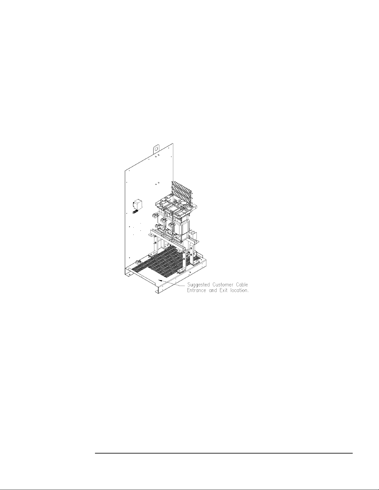
Cable Entry Locations
(Lifting eye is option al)
↓
Figure 3 – Cable Entry Location for Gener al Pur pose units
Field Wiring Connection Terminals
Compression type terminals may be provided for all field wiring connections. The control circuit
terminals will accommodate 18 AWG to 10 AWG wire and should be tightened to 18 in.-lbs. tor que.
The wire size capacity ranges and ti ght e nin g to r q ue fo r t he g r o undi ng a nd p o wer t erminals ar e list ed in
Tables 11a and 11b.
21
Page 22

Table 11 – Motor Power Terminal Wir e Size Cap acity Range and Tightenin g Tor que (Cu or
1 AWG (7 & 19 strand only)
KMG55C to KMG130C
KMG160C to KMG200C
KMG250A to KMG305A
KMG250C to KMG305C
4 AWG - 600 MCM or
(2) 1/0 AWG - 250 MCM
500
4 AWG - 600 MCM or
(2) 1/0 AWG - 250 MCM
500
KMG362A
KMG362C to KMG420C
(2) 4 AWG - 350 MCM
275
(2) 4 AWG - 350 MCM
275
KMG420A to KMG600A
KMG500C to KMG600C
(2) 2 AWG - 600 MCM
500
(2) 2 AWG - 600 MCM
500
KMG750A
(3) 2 AWG - 600 MCM
375
(3) 2 AWG - 600 MCM
375
KMG55A
14 - 1/0 AWG
200
22 - 16 AWG
1 AWG (7 & 19 strand only)
25
KMG65A to KMG130A
KMG55C to KMG130C
6 - 2/0 AW G
120
6 - 2/0 AW G
120
KMG160A to KMG200A
KMG160C to KMG200C
6 AWG - 250 MCM
275
6 AWG - 250 MCM
275
KMG250C to KMG305C
(2) 1/0 AWG - 250 MCM
(2) 1/0 AWG - 250 MCM
KMG362C to KMG420C
KMG420A to KMG600A
KMG500C to KMG600C
(2) 2 AWG - 600 MCM
500
(2) 2 AWG - 600 MCM
500
Al) - Industrial
KMG IND
Model Numbers
KMG8A to KMG55A
KMG8C to KMG45C
KMG65A to KMG130A
KMG160A to KMG200A
6 AWG - 250 MCM 275 6 AWG - 250 MCM 275
Ground Lug
Wire Size
14 - 1/0 AWG 200 22 - 16 AWG
6 - 2/0 AWG 120 6 - 2/0 AWG 120
Torque
(in.-lb.)
Input and Output
Motor Power
Wire Size
14 - 6 AWG
4 - 2 AWG and
Torque
(in.-lb.)
25
30
35
Table 11b – Motor Power Terminal Wire Size Capacity Range and Tightening Torque (Cu or
Al) – General Purpose
KMG GP
Model Numbers
KMG45C
KMG250A to KMG305A
KMG362A
4 AWG - 600 MCM or
(2) 4 AWG - 350 MCM 275 (2) 4 AWG - 350 MCM 275
Ground Lug
Wire Size
Input and Output
Motor Power
Torque
(in.-lb.)
500 4 AWG - 600 MCM or
Wire Size
14 - 6 AWG
4 - 2 AWG and
Torque
(in.-lb.)
30
35
500
Connection Diagram
Figure 4 shows the typical wiring connections between the MotorGuard and the VFD and motor. Note
that separate conduits may be required for the control power and fault contact wiring. Refer to the
instructions for the VFD or other eq uipment to which the fault contact is connecte d.
22
Page 23

Figure 4 – Typical Connection Diagram
Caution
For units rated less than 100 amps, use copper or aluminum wire with an insulation temperature rating
T1
T2
T3
G
Motor
U
V
W
G
T1
T2
T3
MotorGuard
6
7 8
Fault
Output
L1 L2
Control
Power
L1(R)
L2(S)
L3(T)
G
(U)T1
(V)T2
(W)T3
G
Ext Fault
Input
Variable
Frequency
Drive
Grounding
The MotorGuard panel equipment grounding lug must be connected to the ground of the premises
wiring syste m. T he eq ui p me nt gro und i n g c on ne ct io n mu st c o nform to the req uir e ments of the Na tional
Electric Code (NEC) and/or any other codes that apply to the installation site. The ground connectio n
must be made using a wire conductor. Metallic conduit is not a suitable grounding conductor. The
integrity of all ground connections should be periodically checked.
Power Wiring
Connect the o utput of the V FD, terminals T1(U), T2( V), & T3(W), to the input of the MotorGuard,
terminals U, V, & W. Connect the motor to the output of the MotorGuard, terminals T1, T2, & T3.
Use wire that is appropriate for the voltage and current rating of the motor.
of 60 °C or higher.
For units rated 100 amps or more, use copper or aluminum wire with an insulation temperature rating
of 75 °C or higher.
The wire size and the voltage rating s must conform to the requirements of the National Electrical
Code and/or other applicable electrical codes.
Be sure to also follow the moto r wirin g instructions provided in the instruction manual for the VFD.
Control Wiring (for units with boards)
Connect control power to the MotorGuard. Be sure to provide fuses or other appropriate protection for
the control power wiring. Make sure that the voltage and VA capacity of the control power source
matches the MotorGuard's control power input ratings. Refer to the drawings shipped with the unit.
Connect the MotorGuard faul t output relay contacts to the appropr iate fault monitoring cir cuit. It may
be connected to the VFD or to some supervisory control or alarm annunciation equipment.
23
Page 24

MotorGuard Operation
Caution
Adjustments
Monitor Board Settings (for units with boards)
The monitor board configuration switches are factory set and should not be changed. The monitor
board component layout is shown in Figure 5 in the Maint enance and Service sec tion on a follo wing
page. Make sure that the configuration switches are set as follows:
♦ For 480 volt models: Set all sections of S1 to ON.
Alarm level dv/dt = 1000 V/μs.
Alarm level peak voltage = 1000 V
♦ For 600 volt models: Set all sections of S1 to OFF.
Alarm level dv/dt = 1500 V/μs.
Alarm level peak voltage = 1500 V
Variable Frequency Drive Settings
Make sure that the variable frequency drive is set for operation modes and ranges that are compatible
with the Mot orGuard:
♦ Maximum output frequency: 80 Hz
♦ PWM switching fre quency between 2 kHz and 12 kHz, ideally 4 kHz to 8 kHz. Since the
MotorGuard removes most of the harmonic content from the output waveform, quiet
motor operation should be achieved with a swit ching frequency setting within this range.
♦ Mode of operation: "scalar" or "V/Hz" without DC brak ing unless the drive applications has
been confirmed by TCI Technical Support
Caution
Start Up (Commissioning)
Thoroughly check the i nstallation before applying power and operating the equ ipment for the
first time.
Never Operate the MotorGuard without a load connected to its output terminals.
Before Applying Power for the Fir st Time
Inspect the installation to make sure that all equipment has been completely and correctly installed in
accordance with the Installation Guidelines section of this manual.
Before Operating the VFD for the First Ti me
♦ Make sure that the MotorGuard monitor board configuration switches are properly set as
described above.
♦ Make sure that the variable frequency drive is set for operation modes and ranges that are
compatible with the MotorGuard as described above.
Operation
Since the MotorGuard is a passive filter, it is always operating whenever the variable frequency drive
is operating. Whenever the VFD is operating, control power should be applied to the MotorGuard so
that the MotorGuard's cooling fan will opera te and prevent it from overheating. Control p ower is also
required for the performance mo nito r i ng a nd fa ult wa r nin g c ir cui t.
24
Page 25

Maintenance a nd Service
MotorGuard Reliability and Service Life
The MotorGuard has been designed to provide a service life that equals or exceeds the life of the
variable frequency drive. It has been thoroughly tested at the factory to ensure that it will perform
reliably from the moment it is put into service. T he follo wing per iod ic maintenance is recommended to
ensure that the MotorGuard will always perform reliably and provide the expected service life.
Periodic Maintenance
Warning
Only qualified electricians should carry out all electrical installation and maintenance work on
the MotorGuard.
Disconnect all sources of power to the VFD and MotorGuard before working on the equipment.
Do not attempt any work on a powered MotorGuard.
Check to see that the installation environment remains free from exposure to excessive dirt and
contamina nts. Refer to the Pre-installatio n P lanning section of this manual.
Check to make sure that the enclos ure ventilation openings are clean and unobstructed.
Clean the air filter in units that have filtered a ir inlets. Clean as o ften as necessary to preve nt dirt build-
up from impeding air flow.
Inspect the interior of the enclosure for signs of overheated components. Clean the interior of the
enclosure whenever excess dirt has accumulated.
Check the integrity of al l power, ground, and co ntr ol wiri n g co nnec ti o ns.
All electrical connections must be re-torqued annually.
For Units with Boards:
Check the status indica ting lights on the monitor board.
Check the o peration of t he cooling fan.
25
Page 26

Troubleshooting
fore working on the equipment.
J1 J2
J3 J4 J5
J6
(T1)J7(T2)J8(T3)
1 2 3 4
O
N
D1
S1
D9
Fault
Relay
K1
120 VAC
Motor Voltage
(480/600 VAC)
Fault LED
(yellow)
Control
Power
LED
(red)
Configuration
Switch
1 2 3
4
O
N
4 3
2 1
ON
Warning
Only qualified electricians should carry out all electrical installation and maintenance work on
the MotorGuard.
Disconnect all sources of power to the VFD and MotorGuard be
Do not attempt any work on a powered MotorGuard.
Monitor Board (for units with boards)
Figure 5 shows the component layout of the monitor board. The monitor board contains the fault alarm
relay and the status lights which are d escribed b elow.
Figure 5 – Monitor Board Component Lay out
Fault Alarm Relay
The fault alarm relay is energized when control power is applied to the MotorGuard and the output
waveform dv/dt and peak voltage are within specified limits. If the dv/dt or peak voltage limits are
exceeded, the fault relay is de-energized. A set of form C contacts are provided for customer use.
The fault relay contact may be connected to the VFD external fault input or other supervisory control
or alarm annunciation equipment. A MotorGuard fault alarm indicates that the MotorGuard is not
providing adequate dv/dt and peak voltage protection. If the drive operation continues during a fault
condition, the motor or other equipment may be damaged.
26
Page 27

Status Lights (for units with LED s)
During normal operation, both the green LED and the yellow LED are illuminated. The green LED
indicates that control po wer is applied to the monitor board. The yellow LED indicates that the fault
relay is energized.
If the green LED is not illuminated, p ossible causes include:
♦ The source of control power is shut off.
♦ A fuse or other protective device external to the MotorGuard has interrupted control
power. There may be a short circuit, ground fault, or overload condition in the
MotorGuard or in some other wiring or equipment connected to the same source of
control power.
♦ A primary or secondary control power transformer fuse has blown in the MotorGuard.
There is probably a short circuit, ground fault, or overload condition in the MotorGuard.
Check for evidence of damaged, burned, or overheated wiring or components.
♦ Check the followi ng items:
Control circuit wiring
Control circuit transformer
Cooling fan
Monitor board
If the yellow LED is not illuminated, the monitor board has detected o ne or more of the following
MotorGuard output fault conditions:
♦ The output waveform dv/dt exceeds the rated maximum (1,000 V/μs for 480 V units and
1500 V/μs for 600 V units).
♦ The output waveform peak voltage exceeds the selected maximum (1000 V for 480 V units
and 1500 V for 600 V units).
The following conditions can cause MotorGuard output faults:
♦ Bl own R -C power circuit fuses
If fuses are blown, check for damaged components or wiring in the R-C power circuit.
Check for discolored or burned components and deformed or leaking capacitors.
Damaged components can be caused by overheating – check fan. Components can also
be damaged if the VFD has been operating improperly or out of range for proper
MotorGuard performance.
♦ Damaged R-L-C power circuit components
Components can be damaged without blowing f us es. See above.
♦ VFD operating improperly or out of range for proper MotorGuard performance
♦ Problem with VFD or motor
♦ Loose power circuit wiring connections
27
Page 28
Fuses
8
2
8
2
12
2.5
10 2 16 4 12
2.5
23 6 20 5 30 8 25
6
35 9 28
7
45
12
35 9 55
15
45
12
65
20
55
15
80
20
65
20
110
30
80
25
130
35
110
30
160
40
130
35
200
50
160
40
250
70
200
50
305
80
250
70
362
90
305
80
420
110
362
90
480
125
420
110
600
150
500
125
750
200
600
150
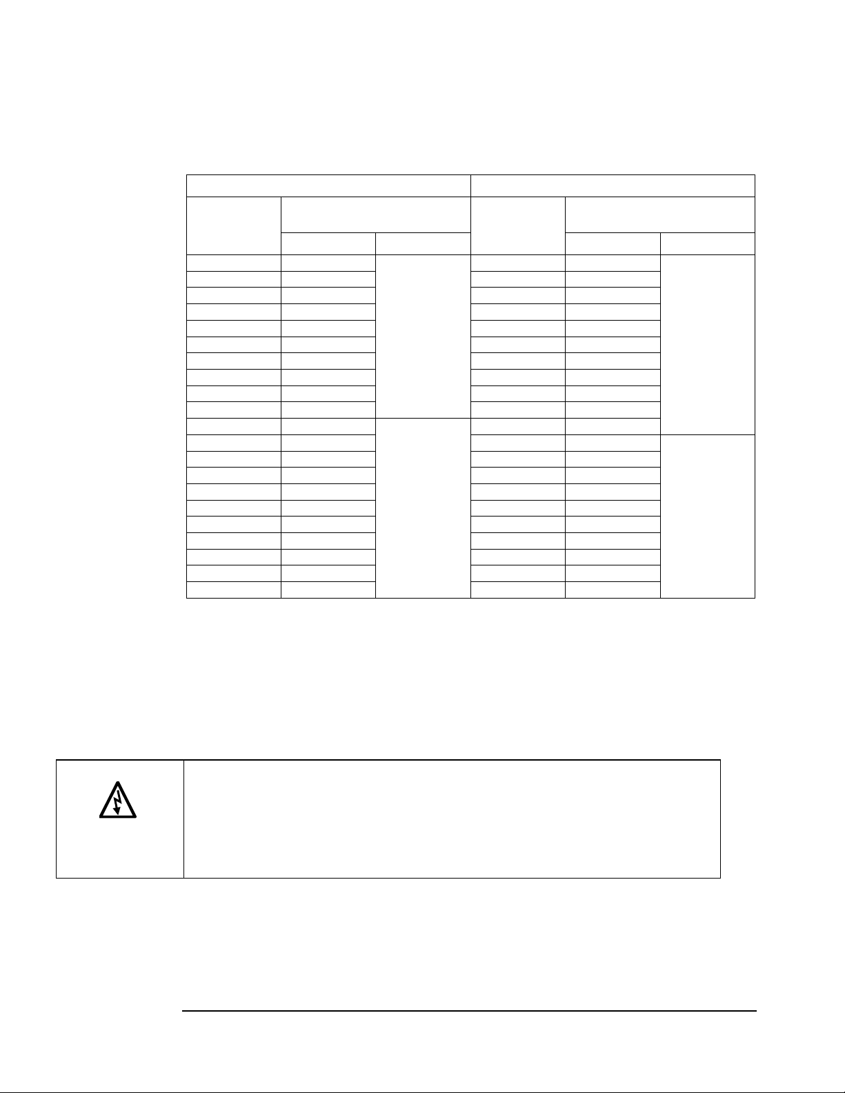
Table 12 lists the specifications for the RC po wer circuit fuses in the MotorGuard.
Table 12 – RC Power Circuit Fuses for Industrial Model
480 V Models 600 V Models
MotorGuard
Rating
(Amps)
Power Circuit
Fuse Rating
Amps Type Amps Type
MotorGuard
Rating
(Amps)
Power Circuit
Fuse Rating
Control Circuit Fuses
Refer to the drawings furnished with your MotorGuard for control circuit fuse specifications.
Evaluating MotorGuard Performance
The MotorGuard performance can be evaluated by checking the output voltage waveform with an
oscilloscope.
Class CC
Bussmann
type KLD-R
or equivalent
Class T
Bussmann
type JJS
or equivalent
Class CC
Bussmann
type KLD-R
or equivalent
Class T
Bussmann
type JJS
or equivalent
Warning
Only qualified electricians should carry out all electrical installation and maintenance work on
the MotorGuard.
Exercise ca ution when checking waveforms with an oscilloscope.
Use a dual probe, differential input set-up, or other means of isolating the scope chassis from
the motor voltage.
Disconnect power when attaching and removing the probes.
Typical VFD Waveforms without Filtering
Figure 6 shows two examples of output voltage waveforms for a typical PWM variable frequency
drive. The example labeled "VFD Output Voltage Waveform" is a "clean" waveform as it would
appear with no thing connec ted to the VFD output terminal s. The voltage peaks of this waveform are
about 650 volts for a 480 volt drive. The example labeled "Motor Voltage Waveform" shows the
28
Page 29

typical waveform at the terminals of a motor located a distance away from the VFD. This waveform
has voltage peaks of 1500 volts or higher due to the voltage spikes caused by the reflected wave
phenomenon.
Figure 6 VFD Output Voltage Waveform Motor Voltage Waveform
With Reflected Voltage Spikes
Filter Output Performance
Figure 7 s hows the voltage waveform at the output of the MotorGuard or at the terminals of a motor
connected to the MotorGuard.
Figure 7 Motor Voltage Waveform
Filter ed by the MotorGuard
Replacement Parts
If replacement parts are needed, please contact your TCI representative. To ensure that the
MotorGuard continues to perform to its original specifications, replacement parts should conform to
TCI specifications.
Factory Contacts and Tech Suppor t
For technical support, contact your lo c a l TCI distributor or sales representative.
You can contact TCI directly at 800-824-8282. Select "Customer Service" or "Technical Suppor t" and
have your MotorGuard nameplate information available.
29
Page 30

Drawings
Typical Isometric Drawings and Schematic Diagrams
Typical MotorGuard drawings are provided on the following pages. These drawings provide general
information describing your MotorGuard filter. More specific information is provided by the drawings
shipped wit h the unit. Be sure to ca refully review the information provided by these drawings. This
information takes precedence over the information provided in this manual.
Isometric Drawings
The isometric drawings provide three-dimensional representations of the MotorGuard units. Three
drawings are provided to cover units that are constructed on small, medium, and large size panels. The
rating and dimension tables list the dimensions for the various models. Two additional drawings are
provided to show the power wiring co nnection detail.
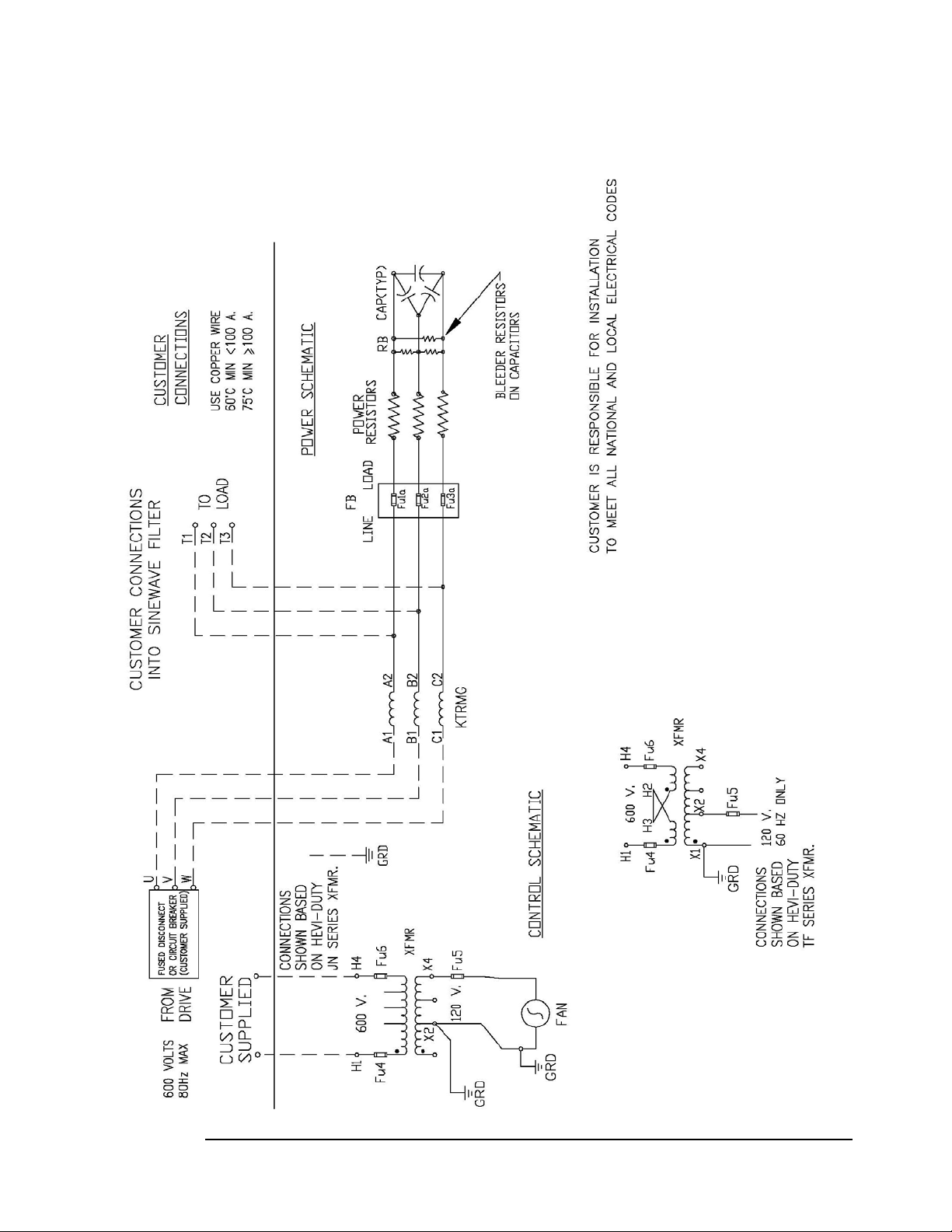
Schematic Diagrams
The schematic diagrams show the details of the MotorGuard circuitry. Two diagrams are provided.
The diagram for the smal l s iz e uni ts s hows the power block that is provided for input and output motor
power wirin g connections. The diagra m for the mediu m and large size units shows i nput and outp ut
motor power wiring connected to terminals on the 3-phase reactor.
30
Page 31

KMG – Capacitor connection may be WYE, consult factory
31
Page 32
KMG
32
Page 33

KMG with Board Option
33
Page 34

KMG with Board Option
34
Page 35

KMG GP NEMA 3R – Small enclosure
KMG GP NEMA 3R – Large enclosure
35
Page 36

KMG Industrial Filter Open – Small enclosure
36
Page 37

KMG Industrial Filter Open – Medium enclosure
37
Page 38

KMG Industrial Filter Open – Large enclosure
38
Page 39

KMG Industrial Filter Type 1 enclosure – Small enclosure
39
Page 40

KMG Industrial Filter Type 1 enclosure – Medium enclosure
40
Page 41

KMG Industrial Filter Type 1 enclosure – Large enclosure
41
Page 42

KMG Industrial Filter with Monitor Board Option (Shown in a small enclosure)
42
Page 43

43
Page 44

Publication No. 24362 Version 1.1 Effective 5/17/14
Printed in USA
TCI, LLC
W132 N10611 Grant Drive
Germantown, WI 53022
Phone: 414-357-4480
Fax: 414-357-4484
Helpline: 800-TCI-8282
Web Site: http://www.transcoi l. c om
44
 Loading...