

Page 1
KLR™ Series
Three Phase Reactors
Applications
PRODUCTSPECIFICATIONS
• Lifetime Warranty
• Performance Guarantee
• K-Rated, UL/ULC-Recognized; CSA-Certified
• 3 Phase, 600V Class
• Gapped Iron Core Inductor
• All Copper Windings
• 40° C Ambient Temp.
• Available with Terminal Options and in NEMA 1
• High quality Bobbin Construction, units 80A and below
• Distributed Gap™ Technology, units 110A and above
• Can tolerate 200% rated l, for at least 3 minutes
• Universal Footprint
TCI KLR™ series three phase AC reactors are intended for use as input filters for
adjustable speed DC drives and as input or output filters for AC-PWM variable
frequency drives. Drive performance is significantly improved, the drives input
rectifier is protected from failure or damage, and drive harmonic demands are tamed
with the addition of a K-rated reactor. KLR reactors act as interface buffers between
solid state power circuits and the line or the motor. (Not unlike the surge protector for
your desk-top PC). All drives, in any application, will benefit when applied with
KLR series reactors.
Before KLR
After KLR
Drives are susceptible to problems caused at their interface to the line or motor.
Some of these issues include AC voltage waveform line notching or cross-talk, DC
bus overvoltage trips, inverter overcurrent and overvoltage, and poor total power
factor. Since all drives demand nonlinear current and voltage, drives demand currents
rich in harmonics.
KLR reactors provide additional circuit inductance which slows rapid changes in
current that are the heart of the problems listed above.
1.) Voltage line notching, or
commutation notching, is caused by
SCR phase-controlled rectifiers. KLR
reactors provide a voltage-dividing
impedance which reduces the depth and
rounds the edges of the notches, thereby
eliminating drive cross-talk, interference,
and equipment damage.
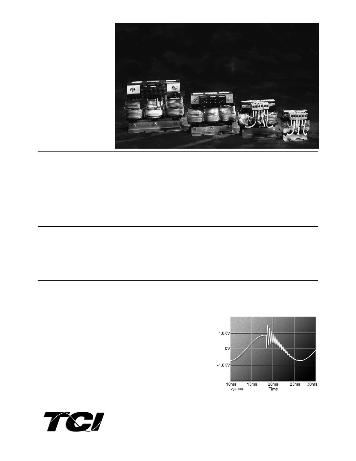
2.) Transient voltages (See Figure 1)
on the AC power lines can cause inrush
currents to an AC-PWM drive, resulting in
an overvoltage condition of the DC bus.
Figure 1
These transient voltage conditions are often caused by utility capacitor switching and
will cause VFDs to shut down without warning. The addition of a KLR reactor will
limit the magnitude of inrush current, preventing trips and component failures. (See
Figure 2.)
Page 2
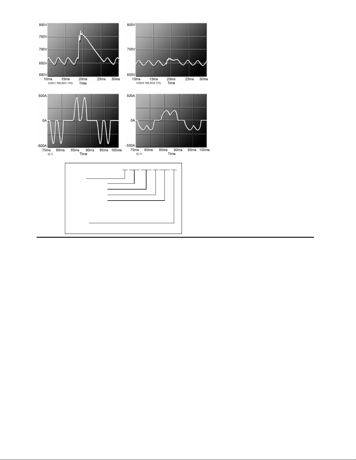
Figure 2
3.) When used as output filters, KLR
reactors prevent inverter instantaneous
overcurrent trips because they provide
needed inductance when the load on an
inverter has an abnormally high
capacitance. For example, if a single
inverter is powering multiple motors, the
load may look capacitive, causing inverter
shutdown.
4.) The addition of a KLR reactor limits
inrush current to the rectifier, rounding the
waveform, reducing peak currents, and
lowering harmonic current distortion.
High peak currents may cause “flattopping” of the voltage waveform.
Reducing those peak currents also reduces
total harmonic voltage distortion. (See
Figure 3.)
KLR
K- Series
Three Phase Reactors
Current Rating (amps)
Impedance Rating
Terminations:
TB: Terminal Block
CB: Copper Bus
PT: Pressure Terminal
Enclosure:
NEMA 1 Sizes: 1-5, 7
Application Instructions
Line reactors are current-rated devices. Therefore, in
order to apply one, you simply need to know the full
load AMPs of the drive with which it will be used and
the amount of impedance that is necessary in the
application. (See NEC Table 430.250 for HP Full Load
Currents.)
Recommendedimpedance levels:
• 2.4 to 3% eliminates bus overvoltage tripping.
• 5 to 6% protects against physical damage to most drive
components and offers harmonic reduction without
added capacitance.
• 1.5% is the recommended input minimum to protect the
drive and is the recommended maximum impedance
when the filter is used as an output device.
Figure 3
48 A B0 T
5.) The addition of a KLR reactor reduces
total RMS current without affecting the
work being done. Therefore, total power
factor is improved.
Universal Footprint/Termination Options
KLR reactors are available with a universal mounting
design. This makes installation much easier for large
distributors, systems integrators, and drive manufacturers
who have pre-drilled back panels or customers with predrilled back panels. Termination options make handling
and connection easier.
Drawings/Specifications
AutoCad compatible *.dxf drawings and Sample Bidding
Specifications of all KLR units are available at
www.transcoil.com or by calling (800) 824-8282.
Manufacturer’s Warranty
KLR reactors are warranted against manufacturer's defect
for the life of the drive they are installed with.
Distributed Gap™ Technology
As reactors and their required air-gaps get bigger, flux
fringing and eddy currents can cause heating and
insulation breakdown. TCI has addressed this issue in
larger KLR reactors by utilizing Distributed Gap™
technology - a construction technique that subdivides a
large gap into two or more smaller gaps. A KLR reactor
built with this technique will run cooler and last longer
than the competitions cheaper single gap products.
Performance Guarantee
Properly sized for the application, a KLR reactor is
guaranteed to end an AC Drive overvoltage tripping
problem. If you install a KLR reactor and a tripping
problem remains, TCI will take back the reactor and pay
shipping both ways. (Offer valid for 60 days from date of
purchase.)
The information contained in this brochure is subject to
update without notice.
 Loading...