

Page 1
TCI’s New KDR Optimized Drive Reactors Deliver Superior Design
And Performance
Customers demand quality and performance at a price that translates to “optimum value”. TCI,
the drive industry’s leading provider of value added technology, is proud to introduce the KDR
Series of Optimized Drive Reactors. This is the latest addition to a family of reactor products with
a reputation for increasing the value and improving the system performance of power inverters.
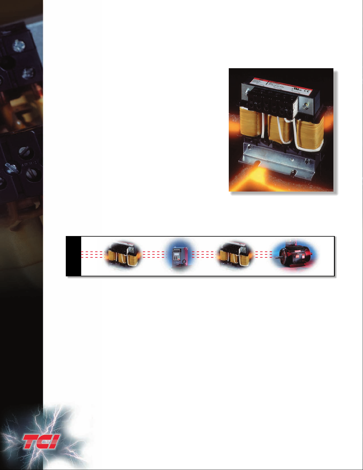
This KDR product has been designed to provide the same
rugged reliability you’ve come to expect from TCI products
in the smallest, lightest product package currently available
in the market. Product models, covering the complete
range of impedance needs, are available for either the line
or load side of a PWM drive. Providing the optimum
selection for your application, TCI’s KDR Optimized Driv e
Reactors are your “Superior Design and Performance”
solution.
KDR Optimized Drive Reactors are warranted against
manufacturer’s defect for the life of the drive with which
they are installed.
Performance Guarantee
Properly sized for the application, a KDR reactor is
guaranteed to eliminate any AC drive o v ervoltage tripping
problems. If a KDR reactor is installed and the tripping
problem remains, TCI will take back the reactor and pay
shipping both ways . (Offer valid for 60 da ys from date of shipment.)
Drawings/Specifications
Autocad® compatible*.dxf drawings and Acrobat Reader® compatible*.pdf drawings of all KDR
Optimized Drive Reactors are available at www.transcoil.com or by contacting
TCI at (800) 824-8282.
UTILITY
KDR DRIVE MOTORKDR
KDR At The Input Of The Drive
KDR Optimized Drive Reactors applied to the line side of a PWM drive will greatly improve the
overall performance of the drive. The additional circuit inductance will reduce AC voltage
waveform line notching, DC bus overvoltage trips, inverter overvoltage, poor total power factor,
and cross-talk.
Typical Problems, Superior Solutions With KDR Reactors:
KDR On The Input to DC Drives
• V oltage line notching, also kno wn as commutation notching, originates in SCR phase-controlled
rectifiers. As the transfer of current takes place, there is a brief period of time where two SCRs
connect during the switching process, causing a short between two of the AC lines. Additional
impedance will reduce the depth and rounds the edges of the notches. This will eliminate drive
cross-talk, interference, and equipment damage.
KDR On The Input to AC Drives
• Transient voltages, commonly caused by capacitor switching, or the switching of large load
blocks, can result in an overvoltage condition of the DC bus. This overvoltage condition will
cause the drive to shut down in order to protect its components. These transients can sometimes
be very severe and too quick for the drive to shut do wn. The addition of a KDR Optimized Drive
Reactor can prevent drive shutdown and even protect components from possible damage.
2
Page 2
• Input line distortion is caused by the non-linear characteristics of drives. The addition of a KDR Optimized
Drive Reactor will limit the inrush current to the rectifier, rounding the waveform, reducing the peak currents and
lowering the harmonic current distortion. High peak currents may cause distortion of the v oltage w a v eform. KDR’ s
reduction of those peak currents also reduces total harmonic voltage distortion at the point of common coupling.
• Drive input currents rich in harmonics result in a decrease in total input power factor to the drive. The addition
of a KDR Optimized Drive Reactor will reduce the RMS current through the reduction in harmonic content,
thereby improving the total power factor.
• Input voltage unbalance may prevent the drive from performing due to subsequent overcurrent conditions
which cause the drive to cease operating. Tests have prov en that the addition of a KDR Drive Reactor to the input
of every drive will help balance the drive input line currents.
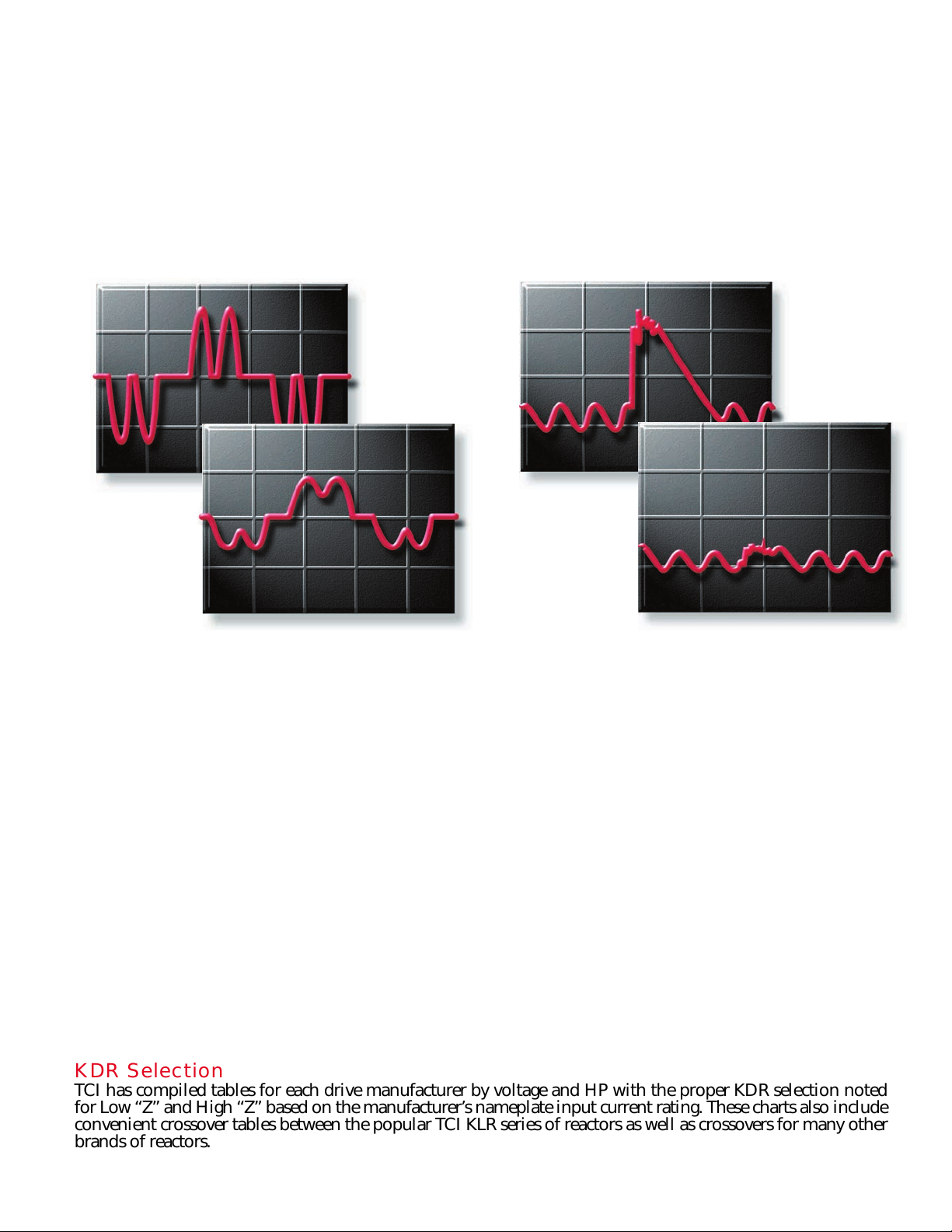
500A
0A
-500A
80ms
75ms
Line
Current
0A
-500A
WITHOUT KDR
85ms
80ms
75ms
85ms 90ms 95ms 100ms
800V
750V
700V
WITH KDR
650V
600V
10ms 15ms
DC Bus
Voltage
WITHOUT KDR
WITH KDR
700V
650V
600V
10ms 15ms 20ms 25ms 30ms
Two Rating Levels, Two Choices, One “Optimized” Answer...the new KDR
Choose TCI’s new KDR Optimized Drive Reactors in two ratings versions, Low “Z” (low impedance) and High
“Z” (high impedance). Input impedance can significantly improve drive performance; however, it should be
noted that as impedance increases, the DC voltage on the VFD’s capacitors actually decreases. This decrease can
become significant enough to cause either an undervoltage trip or excessive motor current in the VFD. The KDR
Optimized Drive Reactors have been designed to provide the best protection for both your drive and your
application.
Use KDR Low “Z” Units For:
These units can be used in any applications where
traditionally either a 1.5% or 3% reactor would be
applied.
Reduction of nuisance tripping caused by:
• Transient voltages caused by capacitor switching
• Line notching
• DC bus overvoltage tripping
• Inverter overcurrent and overvoltage
Additional benefits include:
• Lowering injected percentage of harmonic current
• Improving true power factor
Use KDR High “Z” Units For:
These units can be used in any rugged application
where traditionally a 5% reactor would be applied.
KDR High “Z” offers the same superior benefits as
Low “Z” plus additional benefits which include:
• Helping prevent drive component damage
• Providing maximum harmonic mitigation without
adding capacitance
• Further improving true power factor
• Adding impedance to drives with or without DC
link chokes/reactors when more impedance is desired
due to a relatively stiff source.
• Reducing cross-talk between drives
KDR Selection
TCI has compiled tables for each drive manufacturer by voltage and HP with the proper KDR selection noted
for Low “Z” and High “Z” based on the manufacturer’s nameplate input current rating. These charts also include
convenient crossover tables between the popular TCI KLR series of reactors as well as crossovers for many other
brands of reactors.
3
 Loading...