

Page 1
Harmonics & Power Quality
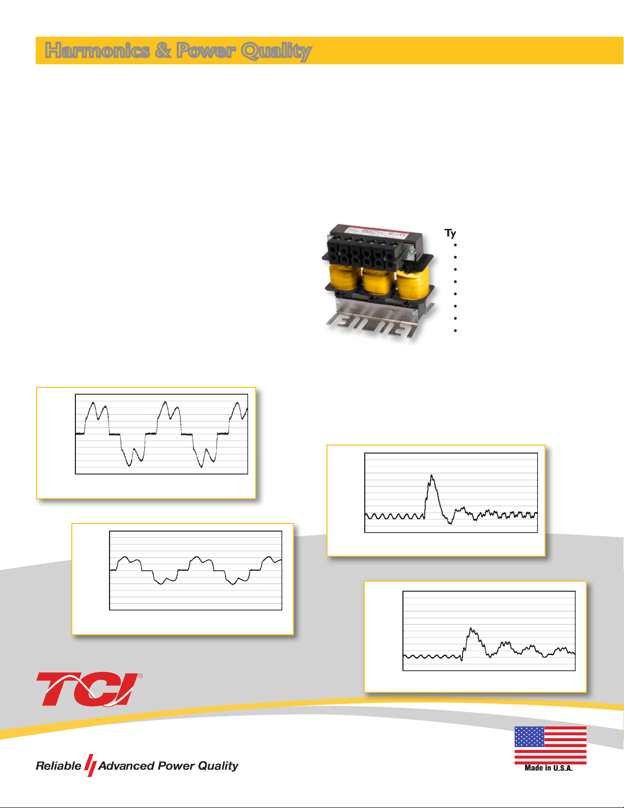
KDR Line Reactor
Variable frequency drives (VFD) are benecial to a wide
range of applications, but contain a power conversion
process that creates current and voltage distortion,
known as harmonics.
Issues caused by harmonics may include:
• Transformer and distribution equipment overheating
• Random breaker tripping
• Sensitive equipment failure
• Poor power factor
KDR Line Reactor
The KDR Line Reactor offers impedance against the ow
of harmonics and other high frequencies that can cause
tripping and equipment failure.
Drives and other sensitive devices are protected by the
KDR from electrical distortion on the line including
harmonics.
Advantages of the KDR Line Reactor
• Extend the life of the motor on the output of the VFD
• Protect other equipment on the line from
operational issues caused by voltage distortion
• Dramatically increase drive uptime by reducing the
likelihood of the drive tripping
• Improve power factor
• Reduce motor heating and audible noise
• Increase system productivity
• Meet IEEE 519-2014
Typical Applications
• Pulp & Paper
• Machining
• Wastewater Treatment Plants
• Oil & Gas
• HVAC Systems
• Irrigation Fields, Farms
• Extruders
• Steel Industry
Harmonic Current Distortion Without KDR
300
200
100
0
Amps
-100
-200
-300
0 403530252015105
Time (ms)
Harmonic Current Distortion With KDR
300
200
100
0
Amps
-100
-200
-300
0 403530252015105
Time (ms)
Warranty
Every TCI line reactor is manufactured in Wisconsin
with high quality materials and is backed by a lifetime
warranty.*
Transient Voltage Without KDR
800
750
700
650
Bus Volts
600
0.48 0.49 0.50 0.51 0.52 0.53 0.54
Time (ms)
Transient Voltage With KDR
800
750
700
650
Bus Volts
600
0.48 0.49 0.50 0.51 0.52 0.53 0.54
Time (ms)
Manufactured in
Germantown, Wisconsin
Page 2
Technical Specications
Environmental Conditions
Operating Temperature
Operating Altitude 2,000 m (6,000 ft) Derating necessary above 2,000 m
Reference Technical Standards
Agency Approvals cUL, UL; UL Recognized, CE Marked
Fundamental Frequency 50/60 Hz
Impedance Protetion Low “Z” and High “Z”
System Voltage 208/240 VAC, 480 VAC, 575/600 VAC, 690 VAC
Short Term Overload Rating Tolerate 200% rated I for a minimum of 3 minutes
Inductance Characteristics
Input and Output Available for either the line or load side of a VFD
Protection (enclosure) Open, UL Type 1, UL Type 3R
DIN Rail version available See website for details
Impedance Options
KDR Line Reactors have been designed to provide the best protection for both your drive and your application.
KDR Optimized Drive Reactors are available in two ratings versions, Low “Z” (low impedance) and High “Z” (high
impedance). Input impedance can signicantly improve drive performance. Select impedance based on the guidelines
below:
Open: 50° C (122° F)
Enclosed: 40° C (104° F)
Minimum 95% L at 110% Load
Minimum 80% L at 150% Load
Use KDR Low “Z” Units For:
Any application where either a 1.5% or 3% reactor
would be applied.
Reduction of nuisance tripping caused by:
• Transient voltages caused by capacitor switching
• Line notching
• DC bus overvoltage tripping
• Inverter overcurrent and overvoltage
Additional benets include:
• Lowering injected percentage of harmonic current
• Improving true power factor
• Reducing cross-talk between drives
• Adding impedance to drives with DC link chokes/
reactors when more impedance is desired due
to a relatively stiff source
Performance Guarantee
Properly sized for the application, a KDR reactor is
guaranteed to eliminate any AC drive overvoltage
tripping problems. If a KDR reactor is installed and the
tripping problem remains, TCI will take back the reactor
and pay shipping both ways. (Offer valid for 60 days
from date of shipment.)
Use KDR High “Z” Units For:
Any application where a 5% reactor would be applied.
KDR High “Z” offers the same superior benets
as Low “Z” plus additional benets which include:
• Helping prevent drive component damage
• Providing maximum harmonic mitigation without
adding capacitance
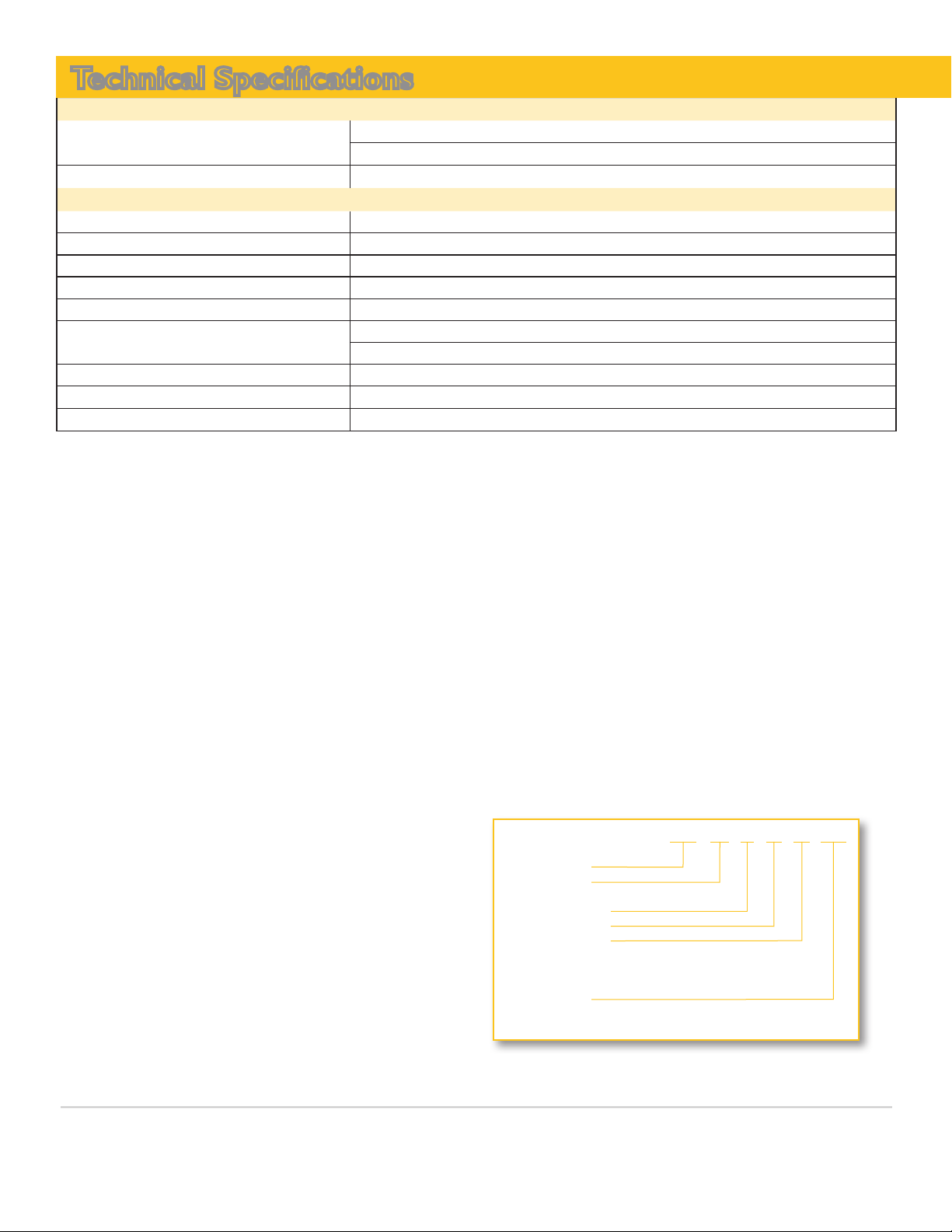
Part Numbering System
KDR UL A 55 H E3R
KDR Series
UL Listed
(Blank if UL Recognized)
Design Frame
Sequence Code
Impedance Rating
L = Low Impedance
H = High Impedance
P = Output Reactor
Enclosure
E01 = UL Type 1
E3R = UL Type 3R
*For the life of the drive
 Loading...