

Page 1
HarmonicGuard
®
Series Drive-Applied Harmonic Filter
Installation, Operation, and Maintenance Manual
TCI, LLC W132 N10611 Grant Drive Germantown, Wisconsin 53022
Phone: 414-357-4480
Fax: 414-357-4484
Helpline: 800-TCI-8282
Web Site: http://www.transcoi l. c om
© 2014 TCI, LLC All rights reserved
Page 2

No part of this publication may be reproduced, stored in a retrieval system, or transmitted in any form or
by any means, mechanical, electr onic, photocopying, recording, or otherwise, without the prior written
permissio n of TCI, LLC. The information in this manual is sub ject to change without no tice. Every
precaution has been taken in the preparation of this manual. TCI, LLC assumes no responsibility for errors
or omissions. Neither is any liab ility assumed for damages resulting from the use of the information
contained in this publication.
Page 3

i HGP I, O, & M Manual
T able of Contents
Introduction .............................................................................................................................. 4
Receiving Inspection and Storage ............................................................................................ 6
Pre-installation Planning .......................................................................................................... 7
Installation Guidelines ............................................................................................................. 8
HGP Filter Operation ............................................................................................................... 9
Installation ............................................................................................................................. 10
Maintenance and Service ....................................................................................................... 11
Product Description ............................................................................................................... 13
Standard Option (S) ............................................................................................................... 16
Contactor Option (C) ............................................................................................................. 17
Fuse Monitor with Contactor Option (F).............................................................................. 18
Fuse Monitor without Contactor Option (G) ....................................................................... 19
Filter and Fuse Monitor Operation ....................................................................................... 20
CP Kit Enclosure (8) with Option (0) .................................................................................... 22
Line Reactor Installation ........................................................................................................ 23
Typical Voltage Distortion Option (0) .................................................................................. 25
High Voltage Distortion Option (1) ....................................................................................... 26
Page 4
STANDARD OPTION (S)
4
Dangerous Voltage Warning: warns o f situation s where high
General Warning: warns of situations that can cause physical
Electrostatic Dischar ge Warning: warns of sit uations in which
General Caution: identifies situatio ns that can lead to a
!
Introduction
Safety Instruc tions Over vie w
This section provides the safety instructions which must b e followed when installing, oper ating, and
servicing t he HarmonicGuard Passive (HGP) filter. If neglected, physical injury or death may follow,
or damage may occur to the filter or equipment connected to the HGP filter. The material in this
chapter must be read and understood before attempting any work on, or with, the product.
The HGP filter is intended to be connected to the input terminals of one or more VFDs. Three -phase
power is connected to the input terminals of the HGP and power is supplied to the VFD or VFDs
through the HGP. T he instr uctio ns, and particu larly t he saf ety inst ructio ns, for t he VFDs, motors, and
any other related equipment must be read, understood, and followed when working on any of the
equipment.
Warnings and Cautions
This manual provides two types of safety instructions. Warnings are used to call attention to
instructions that describe step s that must be taken to avoid conditions that can lead to a serious fault
condition, physical injury, or death.
Cautions are used to call attention to instructions that describe steps that must be taken to avoid
conditions that can lead to a malfunction and possible equipment damage.
Warnings
Readers are informed of situations that can result in serious physical injury and/or serious damage to
equipment with warning statements highlighted by the following s ymbo ls:
Warning
Warning
Warning
voltage can cause physical injury and/or damage equipment.
The text next to this symbol describe s ways to avoid the
danger.
injury and/ or damage equipment by means other than
electrical. The text next to this symbol describes ways to avoid
the danger.
an electrostatic discharge can damage equipment. The text next
to this symbol describes ways to avoid the danger.
Cautions
Readers are informed of situations that can lead to a malfunction and possible equipment damage with
caution statements:
Caution
malfunction and possible equipment damage. The text
describes ways to avoid the situation.
Standard Option (S) HGP IOM Manual
Page 5
STANDARD OPTION (S)
5
Be sure to read, understand, and follow all safety instructions.
Only qualified electricians should carry out all electrical
All wiring must be in accordance with the National Electrical
Disconnect all power before working on the equipment.
The HGP filter, drive, motor, a nd other connected equipment
After switching off the power, always allow 5 minutes for the
capacitors have discharged before beginning work.
!
!
!
General S afety Ins truct ions
These safety instructions are intended for all work on the HGP. Additional safety instructions are
provided at appropriate points on other sections of this manual.
Warning
Warning
Warning
Warning
Warning
Warning
installation and maintenance work on the HGP filter.
Code (NEC) and/or any other codes that apply to the
installation site.
Do not attempt any work on a powered HGP filter.
must be properly grounded.
capacitors in the HGP filter and in the drive to discharge before
working on the HGP, the drive, the motor, or the connecting
wiring. It is a good idea to check with a voltmeter to make sure
that all sources of power have been disconnected and that all
Standard Option (S) HGP IOM Manual
Page 6
STANDARD OPTION (S)
6
Product Family
Warranty Period
KLR, KDR
For the life of the drive with which they are installed.
One (1) year of useful service,
HGP, HG7, KH, 3H, KRF
Three (3) years from the d ate of shipment.
KCAP, KTR, KMP
Five (5) years from the date of shipment.
One (1) year of useful service,
not to exceed 18 months from the date of shipment.
Receivi ng Inspection and Storage
Thank you fo r select ing the H armonicGuard Passive (HGP) filter. TCI has produced this filter for use
in many variable frequency drive (VFD) applic ations that require input power line harmonic current
reduction. This manual describes how to install, operate and maintain the HGP filter.
Receiving Inspection
The HGP filter has been thoroughly inspected and functionally tested at the factory and carefully
packaged for shipment. When you receive the unit, you should immediately inspect the shipping
container and report any damage to the carrier that de livered the unit. Verify that the part number o f
the unit you received is the same as the part number listed on your purchase order.
TCI Limited Warranty Policy
TCI, LLC (“TCI”) warrants to the original purchaser only that its products will be free from defects in materials
and workmanship under normal use and service for a period originating on the date of shipment from TCI and
expiring at the end of the period described below:
KLC, KLCUL, KMG,
V1k
All Other Products
The foregoing limited warranty is TCI’s sole warranty with respect to its products and TCI makes no other
warranty, representation, or promise as to the quality or performance of TCI’s products. THIS EXPRESS
LIMITED WARRANTY IS GIVEN IN LIEU OF AND EXC LUDES ANY AND ALL EXPRESS OR IMP LIED
WARRANTIES INCLUDING, WITHOUT LIMITATION, ANY IMPLIED WARRANTY OF
MERCHANTABILITY OR FITNESS FOR A PARTICULAR PURPOSE.
This warranty shall not apply if the product was:
a) Altered or repaired by anyone other than TCI;
b) Applied or used for situations other than those originally specified; or
c) Subjected to negligence, accident, or damage by circumstances beyond TCI’s control, including but not
limited to, improper storage, installation, operation, or maintenance.
If, within the warranty period, any product shall be found in TCI’s reasonable judgment to be defective, TCI’s
liability and the Buyer’s exclusive remedy under this warranty is expressly limited, at TCI’s option, to (i) repair or
replacement of that product, or (ii) return of the product and refund of the purchase price. Such remedy shall be
Buyer’s sole and exclusive remedy. TCI SHALL NOT, IN ANY EVENT, BE LIABLE FOR INCIDENTAL
DAMAGES OR FOR CONSEQUENTIAL DAMAGES INCLUDING, BUT NOT LIMITED TO, LOSS OF
INCOME, LOSS OF TIME, LOST SALES, INJURY TO PERSONAL PROPERTY, LIABILITY BUYER
INCURS WITH RESPECT TO ANY OTHER PERSON, LOSS OF USE OF THE PRODUCT OR FOR ANY
OTHER TYPE OR FORM OF CONSEQUENTIAL DAMAGE OR ECONOMIC LOSS .
The foregoing warranties do not cover reimbursement for removal, transportation, reinstallation, or any other
expenses that may be incurred in connection with the repair or replacement of the TCI product.
The employees and sales agents of TCI are not authorized to make additional warranties about TCI’s products.
TCI’s employees and sales agent’s oral statements do not constitute warranties; these shall not be relied upon by
the Buyer, and are not part of any contract for sale. All warranties of TCI embodied in this writing and no other
warranties are given beyond those set forth herein.
TCI will not accept the return of any product without its prior written approval. Please consult TCI Custo mer
Service for instructions on the Return Authorization Procedure.
not to exceed 18 months from the date of shipment.
Storage Instructions
If the HGP filter is to be stored before use, be sure that it is stored in a location that conforms to
published storage humidity and temperature specifications stated in Table 1 (HarmonicGuard Passive
Filter Technical Specifications). Store the unit in its original packaging.
Standard Option (S) HGP IOM Manual
Page 7
STANDARD OPTION (S)
7
Unless specifically labeled as approved for such use, this equipment is not
!
Pre-installation Planning
Verify th e A pplicat ion
HGP Ratings
Make sure that the HGP filter is correct for the application. The volta ge ratings o f the filter must match
the input voltage rating of the connected drive. The horsepower and current ratings of the filter must be
appropriate for the connected load.
Select a Suitable Location
Environment
Locating the HGP in a suitable environment will help ensure proper performance and a normal
operating life. Refer to the environmental sp ecifica tions li sted in Table marke d on t he u ni t' s na me p late,
and/or noted on the drawings furni s hed with the unit.
Warning
The unit must be installed in an area where it will not be exposed to:
♦ Direct sunlight
♦ Rain or dripping liquids (unless filter is in a Type 3R enclosure)
♦ Corrosive liquids or gasses
♦ Explosive or combustible gases or dust
♦ Excessive airborne dirt and dust
♦ Excessive vibration
suitable for use in an explosive atmosphere or in a "Hazardous (Classified)
Location" as defined in article 500 of the National Electrical code.
Working Space
Provide sufficient access and working space around the unit to permit ready and safe installation,
operation and maintenance. Make sure that the installation conforms to all working space and
clearance requirements of the National Electrical Code (NEC) and/or any other applicable codes.
Provide sufficient unobstructed space to allow cooling air to flow through the unit.
Mounting an Open Panel Unit
If you are moun ting an open p anel unit in your own encl osure, you must p rovide an enclo sure that is
adequately sized and ventilated sufficiently to pre vent overheating. The ratin g and dimension tables for
open panel units list the watts of heat loss dissipated by the HGP filter. The maximum temperature of
the air around the HGP filter capacitors, line reactor, and tuning reactor should not exceed 50°C
(122°F).
Power Wiring
When selecting a mounting location for the HGP filte r, plan for the routing of the power wiring.
Route the conduit and wir ing from the power source to the filter and then to the VFD.
The HGP is provided with internal fuses.
Standard Option (S) HGP IOM Manual
Page 8

STANDARD OPTION (S)
8
Use copper wire that is appropriate for the voltage and current rating of the
rating of 75°C or higher.
Installa tion Guidelines
Mounting
The HGP must be mounted vertically on a smooth, solid surface, free from heat, dampness, and
condensation.
Wiring
Cable Entry Locations
The enclosed HGP filters are not provided with enclosure wir ing kno c ko ut s. A loc at io n can be select ed
at the time of installation. Typical or recommended cable entry locations are shown in the drawings
section of this manua l .
Field Wiring Connection Terminals
Compression type terminals are provided for all field wiring connections. The wire size capacity
ranges and tightening torques for all field wiring connections are listed in the drawings and other
information shipped with the uni t .
Grounding
The HGP pane l equipme nt-groundi ng lug mu st be conne cted to the ground of the wir ing s ystem. The
equipment-grounding connection must conform to the requirements of the National Electric Code
(NEC) and/or any other codes that apply to the installation site. The ground con nection must be made
using a wire conductor . Metallic conduit is not a suitable ground ing conductor. T he integrity of all
ground connections should be periodically checked.
Power Wiring
Caution
Connect three-phase power of the appropriate voltage and current capacity to the circuit protective
device to the HGP input power terminals.
Note: in large units, the input power conductors are connected directly to the input terminals on the
line reactors.
Connect the output terminals o f the HGP to the input power terminals of the VFD.
Note: in la rge unit s, the o utput power conductors are connected directly to the output terminals on the
line reactors. Refer to the VFD installation instructions for additional information.
equipment. The wire selection must conform to the requirements of the
National Electrical Code and/or other applicable electrical codes.
For units rated less than 100 amps, use wire with an insulation temperature
rating of 60°C or higher.
For units rated 100 amps or more, use wire with an insulation temperature
Standard Option (S) HGP IOM Manual
Page 9

STANDARD OPTION (S)
9
Thoroughly check the installation before applying power and operating
HGP Filter Operation
Caution
the equipment for the first time.
Before Applying Power for the Fir st Time
Inspect the installation to make sure that all equipment has been completely and correctly installed in
accordance with the Installation Guidelines section of this manual.
♦ Check to see that the cooling fan(s) a re operating in units so equipped .
♦ Check to make sure power connections are torqued to recommended torque value.
Operation
Since the HGP is a passive filter, it is always operating whenever the drive is operating.
Standard Option (S) HGP IOM Manual
Page 10

10
Installation
This manual pro vid es gene ra l in fo r mati o n desc ri b i ng your HGP filter. Be sure to
notice.
Make sure that the installation lo c a tion will not be exposed to direct sunlight, corrosive or
Select a mounting area that will allow adequate cooling air and maintenance access.
Make sure that all wiring conforms to the requirements of the National Electric Code (NEC)
Connect the HGP equipment-grounding lug to the system ground of the premises wiring syst em.
Connect three-phase power to the input te rminals of the HGP, L1 , L2 & L3.
Connect the output power terminals, of the HGP, T1, T2 & T3, to the input power terminals of
≤ 40 HP
Use appropriately rated Class J, T, CC, or L fuse less than or equal to 60 A
≥ 50 HP
Use Class J, T, CC, or L fuses appropriate for rating of conductor used to connect to source
STANDARD OPTION (S)
Intended Audience
This manual is intended for use by all personnel responsible for the installation, operation and
maintenance of the HGP filters. Such personnel are expected to have knowledge of electrical wiring
practices, electronic components and electrical schematic symbols.
Additiona l Infor mation
Caution
carefully review the more specific information that is provided by the drawings
shipped with the unit. Information provided by the drawings takes precedence
over the information provided in this manual.
The ratings, dimensions and weights given in this manual ar e approximate and
should not be used for any purpose requiring exact data. Contact the factory in
situations where certified data is r e quired. All data is subject to change wit hout
Installation Checklist
The following are the key points to be followed for a successful installation. These points are
explained in detail in the following sections of this manual.
combustible airborne contaminants, excessive dirt or li quids.
and/or other applicable electrical codes.
Use a properly sized grounding conductor.
the VFD.
100 kA SCCR Fusing Requirements
Below is a table of line fusing requirements that must be supplied to comply with the 100kA SCCR
rating.
Size Required Action(s)
Standard Option (S) HGP IOM Manual
Page 11

STANDARD OPTION (S)
11
Only qualified electricians should carry out all electrical installatio n and
Only qualified electricians should carry out all electrical installatio n and
may result in death or ser ious injur y.
Maintenance a nd Service
HGP Filter Reliabil ity and Servic e Lif e
The HGP has been designed to provide a service life that equals or exceeds the life of the VFD. It has
been thoroughly tested at the factor y to assure that it will perform reliabl y from the time it is put into
service. It is recommended that the following maintenanc e be done once a year to ensure that the
HGP filter will always perform reliably and provide the expected service life.
Periodic Maintenance
Warning
Check to see that the installation environment remains free from exposure to excessive dirt and
contamina nts. Refe r to the Pre-installation Planning section of this manual.
Check to make sure that the enclosure ventilation openings are clean and unobstructed.
Clean the air filter in units that have filtered a ir inlets. Clean as ofte n as necessary to prevent dirt build-
up from impeding air flow.
Check the o peration of the cooling fan.
Inspect the interior of the enclosure for signs of overheated components. Clean the interior of the
enclosure whenever excess dirt has accumulated.
Torque all power wire connections, loose connections can overheat and damage the filter.
All electrical connections must be re-torqued annually.
maintenance work on the HGP filter.
Disconnect all sources of power to the drive and HGP before working on the
equipment. Do not attempt any work on a powered HGP.
Troubleshooting
Warning
maintenance work on the HGP filter.
Disconnect all sources of power to the drive and HGP before working on the
equipment. Do not attempt any work on a powered HGP filter.
The harmonic filter contains high voltages and capacitors. Wait at least five
minutes after disconnecting p ower from the filter before you attempt to
service the harmonic filter. Check for zero voltage between all terminals on
the capacitors. Also, check for zero voltage between all phases of the line side
of the fuses, Fu1(a)–Fu2(a)–Fu3(a), and all input terminals L1, L2 and L3 of
the line reactor (KDR). All set up, maintenance, and tro ubleshooti ng must be
done by a qualified electrician. Failure to follow standard safety procedures
Note: when disconnecting wires from components and terminations, mark the wires to correspond to
their component and terminal connection.
Replacement Parts
If replacement parts are needed, please contact your TCI representative. To ensure that the HGP filter
continues to perform to its original specifications, replacement parts should conform to TCI
specifications.
Standard Option (S) HGP IOM Manual
Page 12

STANDARD OPTION (S)
12
5
1.3
20
30
7.5 3 20
30
10 3 20
30
15 5 30
30
20 6 30
60
25 8 30
60
30
10
30
60
40
15
30
60
50
15
30
80
60
20
50
100
75
25
50
125
100
30
60
150
125
40
80
200
150
45
100
225
200
60
125
300
250
75
150
375
300
90
175
450
350
105
200
500
Fuse Specifications
Table 1a lists the specifications for the fuses in the HGP. Refer also to the drawings and other
information shipped with the unit.
Table 1a – Fuse S peci fications for HGP 48 0 Volt Models
HG7 Rating
(HP)
kVar
Max Branch Circuit
Fuse
(J or T) (J, T or L)
Max Line Fusing
NOTE: Customers must provide line fusing to complete SCCR 100KA rating.
Factory Contacts and Tech Suppor t
For technical support, contact your local TCI distributor or sales representative. You can contact TCI
directly at 800-TCI-8282. Select "Customer Service" or "Tech Support" and have your HGP filter
nameplate information available.
Standard Option (S) HGP IOM Manual
Page 13

STANDARD OPTION (S)
13
Product Descript ion
HGP Drive-Applied Filter
The HGP is a drive-applied harmonic filter designed and developed by TCI to reduce the harmonic
currents drawn from the power source by VFDs. It is suitable for use with 3-phase diode bridge
rectifier loads such as PWM AC drives. SCR or thyristor loads such as DC drives would require a
different filter configuration outside the scope of this product offering. Please contact TCI Technical
Support for additional information.
The HGP is a passive filter connected in series with the input terminals of a VFD or several VFDs that
operate as a group. It is designed to provide a low impedance path for t he major harmonic currents
demanded by the drive. The filter is a stand-alone device that can be furnished in its own enclosure and
mounted adjacent to the drive. It is also available o n an ope n panel fo r mountin g within an enclo sure
with the dri ve or other equipment.
The HGP filters consi st minimally of the following features and components:
♦ A KDR tuned series reactor to prevent system interaction and improve filter performance
♦ An L-C-L filter circuit with:
A TCI 3-phase tuning reactor specifically designed for the HGP filter
High-endurance, harmonic-rated capacitors
♦ Multiple tuned circuits on 700 HP to 900 HP
♦ Bleeder resistors to ensure safe capacitor discharge upon filter shu t down
♦ Cooling fans (on select models) to ensure adequate cooling and safe operating
temperatures
♦ Compression terminals for ease and integrity of all power and control wiring
♦ Fuses, sized to protect the capacitor wiring
Nameplate Data
The following information is marked on the nameplate:
• Part number : encoding is explained on the following page
• FLA: the rate d continuous operating current (RMS amps)
• System Voltage: the rated 3-phase line voltage (RMS vol ts)
• Hz: the rated frequency (60 Hz)
• Phase: 3 – The HGP filter is designed for use onl y with 3-phase power.
• Drawing #: outline and mounting dimension drawing number
• Schematic #: schematic diagram drawing number
• Manufacturing #: for TCI internal use
• Enclosure Type: UL designation or "Open" panel construction
Standard Option (S) HGP IOM Manual
Page 14

STANDARD OPTION (S)
14
FGOption:
0
- St andard
0
- St andard
Option:
0
- Typic al V ol tage Dis tort i on
Option:
1
- High Vol t age Di st ort i on
0
0
Option:
0
- St andard
Option:
- Fus e M oni t or with Cont act or
- Fus e M oni t or without Cont act or
W
- 60 Hz
Enclosure:
0
- Open
Frequency:
Horse P ower:
Vol t age Rat i ng:
A - 480 V
000
Series:
AW1SP150G
H
1
- Type 1
C
- Contac tor
S
- St andard
3
- Type 3R
Part Number Encoding
Figure identifies the significance of each character in the HGP part number. The example part number,
HGP0150AW1S0000 designates an HGP filter that is rated 150 HP, 480 volts, 6 0 Hz . It includ e s a line
reactor, tuni ng reac tor, and capacitors in a UL Type 1 enclosure. It is designed for use with a 150 HP
drive.
Figure 1 – HGP Part N umber Encod ing
Standard Option (S) HGP IOM Manual
Page 15
STANDARD OPTION (S)
15
Voltage ratings
480V, 3 phase, 60 Hz
kVar ratings
1.3 to 270 kVar depending on voltage.
Load types
3-phase diode bridge rectifier loads such as PWM AC drives
Load power range
5 -900 HP
The included series reactors can tolerate 200% of rated current for at
least 3 minutes.
SCCR (short circuit current
rating)
Maximum elevation
3,000 feet (1,000 meters) as standard.
operation above this temperature.
Maximum ambient storage
temperature
Maximum humi d it y,
operating or storage
UL Type 1 enclosure
UL Type 3R enclosure
Insertion Impedance
+/- 10% at full load curre nt
Fusing and protection:
All units have internal fuse prote c tion for the harmonic filter circuit.
50
550 700
2900
60
675 800
3000
75
650 900
3300
100
750 200
1600
125
1000
250
1800
150
1200
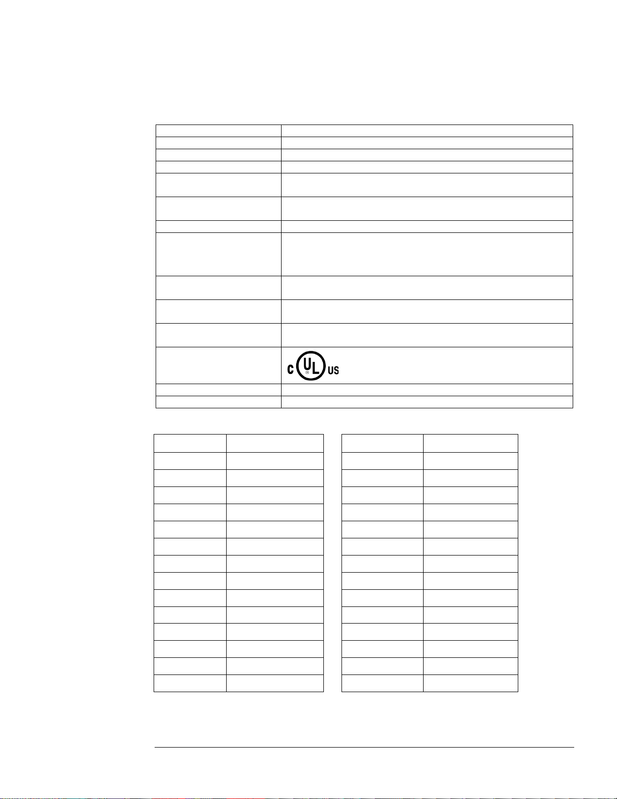
Product Technical Specifications
Tables 1 & 2 list the major technical specifications for the HGP Filter.
Table 1 – HGP Technical Specifications
Current ratings
Standard rating is 100kA.
Maximum ambient operating
temperature
Enclosure options
Agency approvals or
certifications
Table 2 – HGP Watts loss
HP Heat Loss (w atts) HP Heat Loss (w atts)
5 140 200 1600
7.5 150 250 1800
10 175 300 2100
15 250 350 2200
20 275 400 2600
25 250 450 2800
50°C (122°F) – Open Panel; 40°C (104°F) – Enclosed Panel.
Product must be equipped with special cooling provisions for
60°C (140°F)
95%, non-condensing.
UL and cUL Listed to UL508A
30 300 500 3100
40 500 600 2700
Standard Option (S) HGP IOM Manual
Page 16

STANDARD OPTION (S)
16
Standard Option (S)
The Standard Option includes hi gh q ualit y ha r monic-grade capacitors and line reactors. This filter will
meet the majority of application requirements found today. This cost effective product is available as
an open panel version, in a UL Type 1 enclosure, or in an UL Type 3R enclosure. The open panel is
perfect for inclusion in a MCC section or easy installation into industry standard enclosures. The UL
Type 1 enclosed units maintain the same vertical profile as the open panel design. This design is
perfect for applications where floor space is at a premium. The UL Type 3R enclosure protects the
filter from harsh conditions.
Product Description
HGP S Option Filter
The HGP harmonic filter is a drive-applied harmonic filter designed and developed by TCI to reduce
the harmonic curr ents dra wn fr om the po wer sour ce b y VFDs. T he HGP har monic filter is for 480 volt
systems (60 Hz). It is suitable for use with 3-phase diode bridge rectifier loads such as PWM AC
VFDs.
The HGP harmonic filter is a passive filter connecte d in series with the input ter minals of a VFD or
several VFDs that operate as a group. It is designed to provide a low impedance path for the major
harmonic currents demanded by the VFD. The filter is a stand-alone device that can be furnished in its
own enclosure and mounted adjacent to the VFD. It is also available on an open panel for mounting
within an enclosure with the VFD or other equipment.
The HGP Standard Option consists of the following standard features and components:
♦ A KDR tuned series reactor.
♦ A TCI 3-phase tuning reactor specifically designed for the HGP filter.
♦ High-endurance, harmonic-rated capacitors.
♦ Bleeder resistors to ensure safe capacitor discharge upon filter shutdown, located on
capacitors.
♦ Cooling fans (on select models) to ensure adequate cooling and safe operating
temperatures.
♦ Control Power transformer on enclosed units requiring auxiliary cooling fans.
♦ Compression terminals for eas e a nd integrity of all power and control wiring.
♦ Fuses
Standard Option (S) HGP IOM Manual
Page 17

CONTACTOR OPTION (C)
17
Contactor Opti on (C)
The Contactor Option includes a contactor, control power transformer and connection terminals in the
filter circuit which allows the VFD user to control the insertion of this circuit t hrough the use of a relay
contact in the VFD. It is recommended that t he VFD contact be programmed to op en the contactor
below 33% motor power. For variable torque (fan) loads this will be approximately below 70% speed,
so the at-speed contact may be used. This reduces the possibility of leading power factor interacting
with other devices on the power system. Contactor logic should also maintain the contactor closed in
cases where the VFD is bypassed and the filter is not bypassed.
Product Description
HGP C Option Filter
The HGP harmonic filter is a drive-applied harmonic filter designed and developed by TCI to reduc e
the harmonic curr ents dra wn fr om the po wer sour ce b y VFDs. T he HGP har monic filter is for 480 volt
systems (60 Hz). It is suitable for use with 3-phase diode bridge rectifier loads such as PWM AC
VFDs.
The HGP harmonic filter is a passive filter connected in series with the input termi nals of a VFD or
several VFDs that operate as a group. It is designed to provide a low impedance path for the major
harmonic currents demanded by the VFD. The filter is a stand-alone device that can be furnished in its
own enclosure and mounted adjacent to the VFD. It is also available on an open panel for mounting
within an enclosure with the VFD or other equipment.
The HGP Contactor Option consists of the following standard features and components:
♦ A KDR tuned series reactor.
♦ A TCI 3-phase tuning reactor specifically designed for the HGP filter.
♦ High-endurance, harmonic-rated capacitors.
♦ Bleeder resistors to ensure safe capacitor discharge upon filter shutdown, located on
capacitors.
♦ Filter enable/disable contactor with protection and drive interlock provisions.
♦ Cooling fans (on select models) to ensure adequate cooling and safe operating
temperatures.
♦ Control power transformer
♦ Compression terminals for ease a nd integrity of all power and control wiring.
♦ Fuses
♦ Contactor
Contactor Option (C) HGP IOM Manual
Page 18

FUSE MONITOR WITH CONTACTOR OPTION (F)
18
Fuse Monitor with Contactor Option (F)
The Fuse Monitor with Contactor Option includes a voltage monitor module and relay that can be
connected to a VFD or other device. The fuse monitor will indicate a fuse failure and communicate this
condition through the relay to a connected device.
This option includes a contactor, control power transformer, and connection terminals in the filter
circuit which allows the VF D user to control the insertion of t his circuit throu gh the use of a rel ay
contact in the VFD. It is recommended that the drive contact be programmed to open the contactor
below 33% motor power. For variable torque (fan) loads this will be approximately below 70% speed,
so the at-speed contact may be used. This reduces the possibility of leading power factor interacting
with other devices on the power syste m. Contactor logic should also mainta in the contactor closed in
cases where the VFD is bypassed and the f ilte r is not bypassed.
Product Description
HGP F Option Filter
The HGP harmonic filter is a drive-applied harmonic filter designed and developed by TCI to reduce
the harmonic curr ents dra wn fr om the po wer sour ce b y VFDs. T he HGP har monic filter is for 480 volt
systems (60 Hz). It is suitable for use with 3-phase diode bridge rectifier loads such as PWM AC
drives.
The HGP harmonic filter is a passive filter connecte d in series with the input ter minals of a VFD or
several VFDs that operate as a group. It is designed to provide a low impedance path for the major
harmonic currents demanded by the VFD. The filter is a stand-alone device that can be furnished in its
own enclosure and mounted adjacent to the VFD. It is also available on an open panel for mounting
within an enclosure with the VFD or other equipment.
The HGP F Option consists of the follo wi ng standard features and compone nts:
♦ A KDR tuned series reactor.
♦ A TCI 3-phase tuning reactor specifically designed for the HGP filter.
♦ High-endurance, harmonic-rated capacitors.
♦ Bleeder resistors to ensure safe capacitor discharge upon filter shutdown, located on
capacitors.
♦ Filter enable/disable contactor with protection and drive interlock provisions.
♦ Cooling fans (on select models) to ensure adequate cooling and safe operating
temperatures.
♦ Control power transformer
♦ Compression terminals for ease a nd integrity of all power and control wiring.
♦ Fuses
♦ Contactor
♦ Voltage monitor module to report status of fuses to control
Fuse Monitor with Contactor Option (F) HGP IOM Manual
Page 19

FUSE MONITOR WITHOUT CONTACTOR OPTION (G)
19
Fuse Monitor wi thout Contactor Option ( G)
The Fuse Monitor without Contactor Option includes a voltage monitor module and relay that can be
connected to a VFD or other device. The fuse monitor will indicate a fuse failure and communicate this
condition through the relay to a connected device.
Product Description
HGP G Option Filter
The HGP harmonic filter is a drive-applied harmonic filter designed and developed by TCI to reduce
the harmonic curr ents dra wn fr om the po wer sour ce b y VFDs. T he HGP har monic filter is for 480 volt
systems (60 Hz). It is suitable for use with 3-phase diode bridge rectifier loads such as PWM AC
VFDs.
The HGP harmonic filter is a passive filter connecte d in series with the input ter minals of a VFD or
several VFDs that operate as a group. It is designed to provide a low impedance path for the major
harmonic currents demanded by the VFD. The filter is a stand-alone device that can be furnished in its
own enclosure and mounted adjacent to the VFD. It is als o available on an open panel for mounting
within an enclosure with the VFD or other equipment.
The HGP G Option consists of the following s t andard features and components:
♦ A KDR tuned series reactor.
♦ A TCI 3-phase tuning reactor specifically designed for the HGP filter.
♦ High-endurance, harmonic-rated capacitors.
♦ Bleeder resistors to ensure safe capacitor discharge upon filter shutdown, located on
capacitors.
♦ Cooling fans (on select models) to ensure adequate cooling and safe operating
temperatures.
♦ Control Power transformer on enclosed units requiring auxiliary cooling fans.
♦ Compression terminals for ease a nd integrity of all power and control wiring.
♦ Fuses
♦ Voltage monitor module to report status of fuses to control
Fuse Monitor without Contactor Option (G) HGP IOM Manual
Page 20

FITLER AND FUSE MONITOR OPERATION
20
Filter and Fuse Monitor Operation
HGP Filter Overview
The Harmonic Guard Passive (HGP) Filter provides a low impedance path for the major harmonic
currents demanded by Variable Frequency Drives (VFDs). This greatly reduces the amount of
harmonic c urrents flowi ng through the e lectrical po wer distributi on system, bri nging those ha rmonic
currents i n li ne wi th the I E EE -519 standard for harmonic distortion mandated by an increasing number
of utilities.
The HGP Filter includes branch fuses on the harmonic trap circuit capacitors. These fuses are included
in the desi gn to pre ve nt da ma ge to the c apa cito rs i n t he e vent of e xce ssi ve ha rmo nic tra p cur rent if the
filter is misapplied.
HGP Fuse Monitor Overview
The HGP Fuse Monitor Optio n is used in conj unction with the HGP filter to mo nitor the status o f the
HGP branch circuit capacitor fuses and optional contactor. If a blown fuse condition is detected the
HGP Fuse Monitor Option will ener gize a SPDT relay contact. Additionally, the Fuse Monitor Option
is used to indicate the state of the op tional contactor that allows users to re move the capacitors from
the circuit, eliminating the possibility of leading power factor. Finally, the Fuse Monitor Option
provides the additional benefit of detecting drive input voltage phase reversal and loss of phase.
The HGP Fuse Monitor can be connected to a programmable digital input available on most modern
VFDs and/or Programmable Logic Controllers (PLCs). Once the status of the HGP Fuse Monitor is
routed to a programmable digital input the status of the Fuse Monitor can be relayed on the VFDs or
PLCs integrated communications field bus or Industrial Ethernet network interface.
Figure 2 – HGP Filter and Fuse Monitor Option Block Diagram
Filter and Fuse Monitor Operation HGP IOM Manual
Page 21

FITLER AND FUSE MONITOR OPERATION
21
No Input Line Voltage
Not Present
X*
Closed
Open
Input Line Volta ge has
Missing Phase
Input Line Volta ge has
Phase Reversal
Phase
Reversal
HGP Filter has Blown
Trap Fu se
Blown
Trap Fu se
Blown
Fuse
HGP Filter Contactor is
Open
Contactor
Open
Contactor
Closed
Relay Contact
Location
Contact Rating
10A Resistive @ 240V AC
1/3HP @ 120/240V AC
10A Resistive @ 240V AC
1/6HP @ 120/240V AC
Fuse Monitor Operation and Relay Specifications
The fuse monitor relay contac t is a s ingle p ole, doub le thro w (SPD T ) dr y type contact. T er minal Blo ck
connection TBa-7 is the common connection, TBa-6 is the Normally Closed (NC) connection, and
TBa-8 is the Normally Open (NO) Connection.
Table 2 – Fuse Monitor Operation Modes and Output Table
Operating State
HGP Fuse Monitor has
Blown Fuse
Nominal Nominal
*X = don’t care condition
Table 3 – HGP Fi lter Fus e Monitor Rela y Con tact Speci fication s
Normally Open Contact (TBa-7 TBa-8)
Normally Closed Contact (TBa-6 TBa-7)
Input
Voltage
Phase Loss X* Closed Open
Nominal
Nominal
Nominal
HGP
Filter
X* Closed Open
Monitor
N.C. Relay Contact
(TBa-6 TBa-7)
Closed Open
Closed Open
Closed Open
Open Closed
N.O. Relay Contact
(TBa-7 TBa-8)
Figure 3 – HGP Filter Fuse Monitor Typic al Conne ction Cir cuit Di agram
Filter and Fuse Monitor Operation HGP IOM Manual
Page 22

CP KIT OPTION (0)
22
CP Kit Encl osure (8) with Option (0)
The HGP CP Kit Option is a harmonic filter component package designed and developed by TCI to
allow qualified customers to build harmonic filters to reduce the harmonic currents drawn from the
power source by VFDs. The HGP CP Option is available for 480 volt systems (60 Hz). When prop e rl y
designed, assembled, and installed, the completed product is intended to be suitable for use with
3-phase diode bridge rectifier loads such as PWM AC VFDs. SCR or thyristor lo ad s suc h a s DC d rive s
would require a different filter configuration outside the scope of this product offering. Please contact
TCI Technical Support for additional information.
Product Description
HGP CP Kit Option Filter
The HGP CP Kit Op tion is a package of the primary passive filter components needed to build and
install a harmonic filter on a VFD or VFD system. The filter components are tuned to pro vide a low
impedance path for the major harmonic currents demanded by the VFD when fol lowi ng the sc hemat ic
connections used by TCI in the HGP filter.
The HGP CP Option filter component package consists of the following components:
♦ A KDR tuned serie s reactor.
♦ A TCI 3-phase tuning reactor specifically designed for the HGP filter.
♦ High-endurance, harmonic-rated capacitors.
♦ Bleeder resistors to ensure safe capacitor discharge upon filter shutdown, located on
capacitors.
♦ Fasten terminals for wirin g si ngle-phase capacitors (select models
CP KIT OPTION (0) HGP IOM Manual
Page 23

CP KIT OPTION (0)
23
Line Rea ctor Installation
Review all Pre-Installation and Installation instructions at the beginning of this manual.
If you are assembling a CP unit i n your own enc losure, you must provide a n enclosure tha t is adequate ly
sized and ventilated sufficiently to prevent overheating. The maximum temperature of the air around the
HGP filter capacitors should not exceed 50°C (122°F).
KDR Line Re actor In stalla tion Ins tructio n
Recommendations and Considerations:
When instal ling t he KD R Li ne Reactors on the INPUT side of the VFD, please use the follo wing guidelines
when wiring the unit:
The KDR Line Reactor is a 3-phase device and should be wired in series and positioned on the input side of
the VFD.
All Terminal Block connectors will be marked. A1, B1, and C1 are the input terminals where the 3 phases of
incoming power are to be wired. The tap for the filter connection will be marked AT, BT, and CT. Output
terminals will be marked A2, B2, and C2. Do not swap input and output terminals. Units with copper bus or
ring lug terminals are not marked. Wiring from the output te rminals shoul d connect to the input of the VFD.
Refer to NEC wiring practices for appropriate wire sizes for your application.
TCI recommends that these reactors be wired and located as close to the front end of the VFD as possible to
have the greatest success in both protecting the VFD as well as mitigating line harmonics. We reco mmend
this be 10 feet of cable or less.
Reactors generate a lot of heat in normal operations, and their surfaces get very hot. In standard 40°C
ambient or less installations, a clearance of 3 inches on all sides of the reactors and its enclosure is
recommended for assisting in heat dissipation. This is a general guideline for typical applications. If the
reactor is being installed ne xt to a heat sensitive instrument or control device, we recommend reviewing
specific requirements or heat li mitations. Line reactor heat l oss information is availab le in the standard T CI
product literature or on the web at www.transcoil.com.
These reactors are designed to be floor-mounted, or wall-mounted. Large open-style devices should be panel
mounted by incorporating a bracket that would act as a shelf to support the reactor and/or enclosure. When
installing a n open style device in an existing control cabinet, drive cabinet, motor control center, or other
large enclosure, the reactor should be mounted in the lower half of the cabinet to prevent hot spots or
pockets of heat. Locating the reactor in the lower half of the cabinet typically allows better thermal
dissipation and heat convection. Reactors with ducts should be mounted vertically for proper cooling.
Recommendations for CP Kit Usage to Achiev e 100kA SCCR
Panel design using a TCI HGP kit should be performed with appropriate engineering supervision so the
design meets the requirements based on materials you utilize in the construction of your panel, the wiring
practices your shop utilizes, and the actual ambient conditions the components will see in your application.
Wire Sizing
Appropriate wire sizing can be calculated using the information in the fuse specification table
(repeated from Pg. 12 for convenience). Wires need to be sized based on current to be carried, wire
insulation temperature rating, panel temperature rating, bundling of wires, and appropriate codes and
standards. Wire size between the power source and the filter line reactor as well as the line reactor and
the drive input are based rated filter line current. Wire size in the trap circuit is based on rated trap
current. If the capacitor wiring is split into separate capacitor branches, the current each branch carries
is proportional to the value of capacitance in each branch.
CP KIT OPTION (0) HGP IOM Manual
Page 24

CP KIT OPTION (0)
24
5
1.3
20
30
7.5 3 20
30
10 3 20
30
15 5 30
30
20 6 30
60
25 8 30
60
30
10
30
60
40
15
30
60
50
15
30
80
60
20
50
100
75
25
50
125
100
30
60
150
125
40
80
200
150
45
100
225
200
60
125
300
250
75
150
375
300
90
175
450
350
105
200
500
Table 1a – Fuse Specifications for HGP 48 0 Volt Models
HG7 Rating
(HP)
kVar
Max Branch Circuit
Fuse
(J or T) (J, T or L)
Max Line Fusing
NOTE: Customers must provide line fusing to complete SCCR 100KA rating.
Selection of Contactors
As an option, you can incl ude contactors to remove the tra p circuit from the filter under no load o r
light load conditions. Review the impedance of t he line reactor, this isolates the trap cir cuit capacitors
from line transients, removing the need for special capacitor rated contactors in this application.
Contactors in the trap circuit can be selected based on the rated trap circuit current using the UL
general purpose rating of your intended contactors.
Options
TCI fuses the trap circuit to isolate the trap circuit in the case of component damage. Some failures
could leave an unbalanced load on the trap, which can damage additional parts. A fuse in the trap
circuit can be selected based on trap circuit rated current.
SCCR Issues
If you need a n SCCR rating gre ater than the default values of compo nents: For example 1 0 kA for
terminal blocks or 5 kA for contactors, pay attention to component selection and circuit fusing.
Contactors need to be protected by line or trap fusing based on their published SCCR ratings. For trap
circuits less than or equal to 40 HP , the inco ming line cir cuit p rote ction of Class J or Class T r ated less
than or equal to 60 A will result in 10 kA being supplied to the panel, allowing any type of filter
capacitors to be used. Larger filter kits are provided with dry capacitors, which are exempt f rom S C CR
calculations.
CP KIT OPTION (0) HGP IOM Manual
Page 25

VOLTAGE DISTORTION OPTION (0)
25
Typical V oltage Distortion Option (0 )
The Typical Voltage Disto rtion Option, intended for applications with levels of background voltage
distortion less than 2%, i s a co nfiguratio n that e nable s the H GP filter to a chieve lower levels of current
harmonic distortion in applications with lo w backgro und volta ge distor tion. T his per formance op tion is
available in all of the package options.
Typical Voltage Distortion Option (0) HGP IOM Manual
Page 26

HIGH VOLTAGE DISTORTION OPTION (1)
26
High V oltage Distortion Option (1)
The High Voltage Distortion Option, intended for applications with levels of background voltage
distortion of 2% or higher, is a configuration that e nables the HGP filter to achieve lower levels of
current harmonic distortion in ap plications with high background voltage d istortion.
This performance option is availa ble in all of the package options.
High Voltage Distortion Option (1) HGP IOM Manual
Page 27

Page 28

TCI, LLC
W132 N10611 Grant Drive
Germantown, Wisconsin 53022
Phone: 414-357-4480
Fax: 414-357-4484
Helpline: 800-TCI-8282
Web Site: http://www.transcoil.com
© 2014 TCI, LLC All rights reserved
©2014 TCI, LLC Publication No: 28557 Effective: 2/3/2014 Version: B
Printed in USA
 Loading...