

Page 1

Active Harmonic Filter
Installation, Operation, and Maintenance Manual
TCI, LLC
W132 N10611 Grant Drive
Germantown, Wisconsin 53022
Phone: 414-357-4480
Fax: 414-357-4484
Helpline: 800-TCI-8282
Web Site: http://www.transcoi l. c om
© 2014
Page 2

No part of this publication may be re produced, stored in a retrieval system, or transmitted in any form
or by any means, mechanical, electronic, photocopying, recording, or otherwise, without the prior
written permission of TCI, LLC. The information in this manual is subject to change without notice.
Every precaution has been taken in the preparation of this manual. TCI, LLC assumes no
responsibility for errors or omissions. Neither is any liability assumed for damages resulting from the
use of the information contained in thi s p ub lic a tion.
Page 3

T able of Contents
■ Section 1
HGA Quick Start Unit Software Setup.......................................................... 6
■ Section 2
Safety Instructions ...................................................................................... 11
Overview ............................................................................................................................................... 11
Warnings and Caution s ....................................................................................................................... 11
General Safety Instructions ................................................................................................................ 12
General Terminology ................................................................................... 13
■ Section 3
Introduction .................................................................................................. 14
Intended Audience ............................................................................................................................... 14
Additional Information ....................................................................................................................... 14
Installation Checklist ........................................................................................................................... 14
Receiving Inspection and Storage ............................................................. 15
Receiving Inspection ............................................................................................................................ 15
TCI Limited Warranty Policy ............................................................................................................ 15
Storage Instructions ............................................................................................................................. 15
Product Description .................................................................................... 16
Nameplate Data .................................................................................................................................... 18
Part Number Encoding ....................................................................................................................... 19
■ Section 4
Pre-installation Planning ............................................................................. 26
Verify the Application ......................................................................................................................... 26
Select a Suitable Location ................................................................................................................... 26
Mounting an Open Chassis Unit ......................................................................................................... 26
Cooling Diagrams ................................................................................................................................ 26
Page 4

Installation Guidelines ................................................................................ 29
Mounting .............................................................................................................................................. 29
Wiring ................................................................................................................................................... 29
Current Transformer Installation ...................................................................................................... 31
HGA Filter Operation ......................................................................................................................... 45
Adjustments ......................................................................................................................................... 45
Start Up (Commissioning) ................................................................................................................... 45
General Operation ............................................................................................................................... 45
■ Section 5
Maintenance and Service ............................................................................ 46
HGA Reliability and Serv ic e Lif e ....................................................................................................... 46
Periodic Maintenance .......................................................................................................................... 46
Troubleshooting ................................................................................................................................... 51
■ Section 6
HMI Introduction .......................................................................................... 67
Overview ............................................................................................................................................... 67
Additional Information ....................................................................................................................... 68
Receiving Inspection ............................................................................................................................ 68
Installation Guidelines ................................................................................ 69
Checklist ............................................................................................................................................... 69
Location ................................................................................................................................................ 69
Mounting .............................................................................................................................................. 69
Wiring ................................................................................................................................................... 70
■ Section 7
Operation ...................................................................................................... 74
HMI Screen Elements .......................................................................................................................... 75
Initialization ......................................................................................................................................... 76
HMI Screens ......................................................................................................................................... 76
Network Interface ................................................................................................................................ 94
Page 5

■ Section 8
Maintenance ................................................................................................. 96
Clock Battery Replacement ................................................................................................................ 97
Software Field Upgrades ..................................................................................................................... 97
Troubleshooting .......................................................................................... 97
HGA Filter Fault .................................................................................................................................. 98
Interface Module Problem .................................................................................................................. 98
Troubleshooting Notes ......................................................................................................................... 99
Troubleshooting Flow Chart ............................................................................................................... 99
■ Section 9
Appendix – Installation Diagram ................................................................ 99
Appendix – Part Numbering ..................................................................... 101
Appendix – Ethernet/IP Gateway Option ................................................. 101
Introduction ....................................................................................................................................... 101
Wiring ................................................................................................................................................. 101
Configuration ..................................................................................................................................... 102
Register Map ...................................................................................................................................... 103
Operation ............................................................................................................................................ 103
Page 6
!
!
!
■ Section 1
HGA Quick Start Unit Software Setup
Warning
Be sure to read, understand, and follow all safety instructions.
Warning
Warning
Warning
Warning
Warning
Warning
Only qualified electricians should carry out all electrical installation and maintenance work on the
HarmonicGuard Active (HGA) filter.
All wiring must be in accordance with the National Electrical Code (NEC) and/or any other codes that
apply to the installation site.
Disconnect all power before working on the equipment.
Do not attempt any work on a powered HGA filter.
The HGA filter, drive, motor, and other connected equipment must be properly grounded.
The HGA filter may receive power from two or more sources.
Three-phase power is connected to the main input terminals of the HGA filter.
All of these sources of power must be disconnected before working on the HGA filter.
After switching off the power, always allow 5 minutes for the capacitors in the HGA filter and in the
drive to di s charge before working on the HGA filter, the drive, the motor, or the connecting wiring. It
is good practice to check with a voltmeter to make sure that all sources of power have been
disconnected and that all capacitors have discharged before beginning work.
6
Page 7
Select language setting from the language setup
!
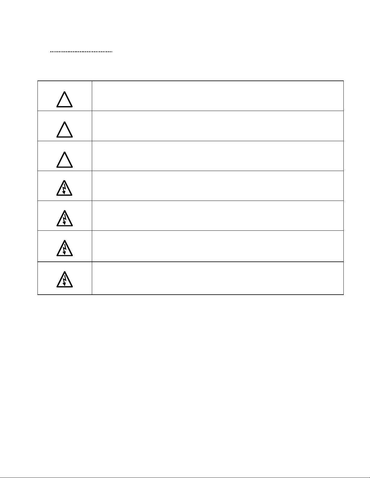
1) Verify unit external connections
• Phase A, B, C power connection,
with positive A-B-C phase rotation expected
• CT H1 Terminal is pointing toward the source
• CT feedback on phases A & C to TB-1
• Leave CT shorting bars in place o n TB-1
• With the HGA circuit breaker open,
energize the source to the HGA
• Close the HGA circuit breaker
• Fans and HMI should come on in < 5 seconds
• HMI will start on Home screen
• Load(s) have an integral 5% line reactance or
equivalent dc bus choke
Warning
Hazardous voltages are present when
unit is ener gi zed
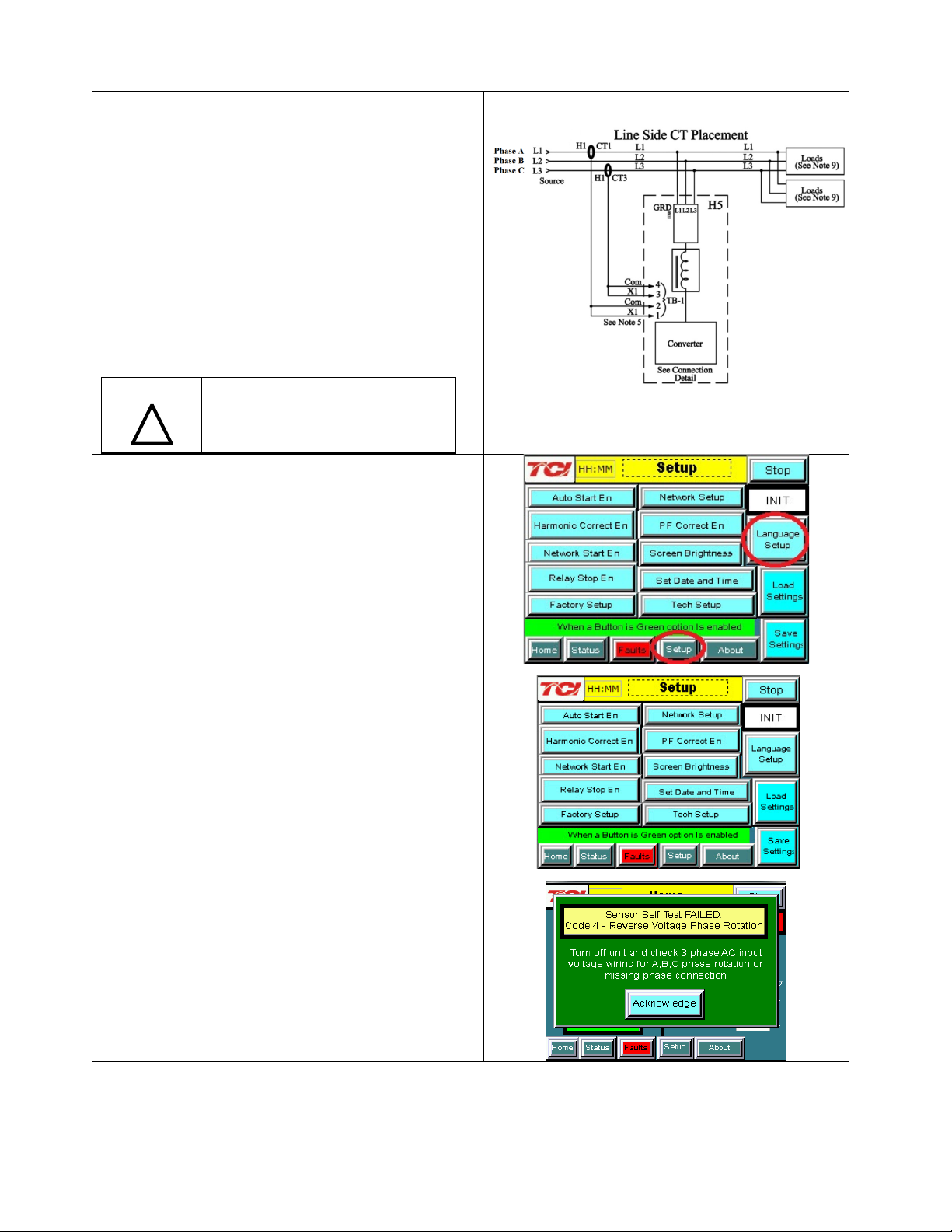
NOTE: Language Selection
• The active filter supports several languages
including English, French and S panish
• Press “Setup” to navigate to Setup screen and
press the “Language Setup” button.
•
pop-up screen.
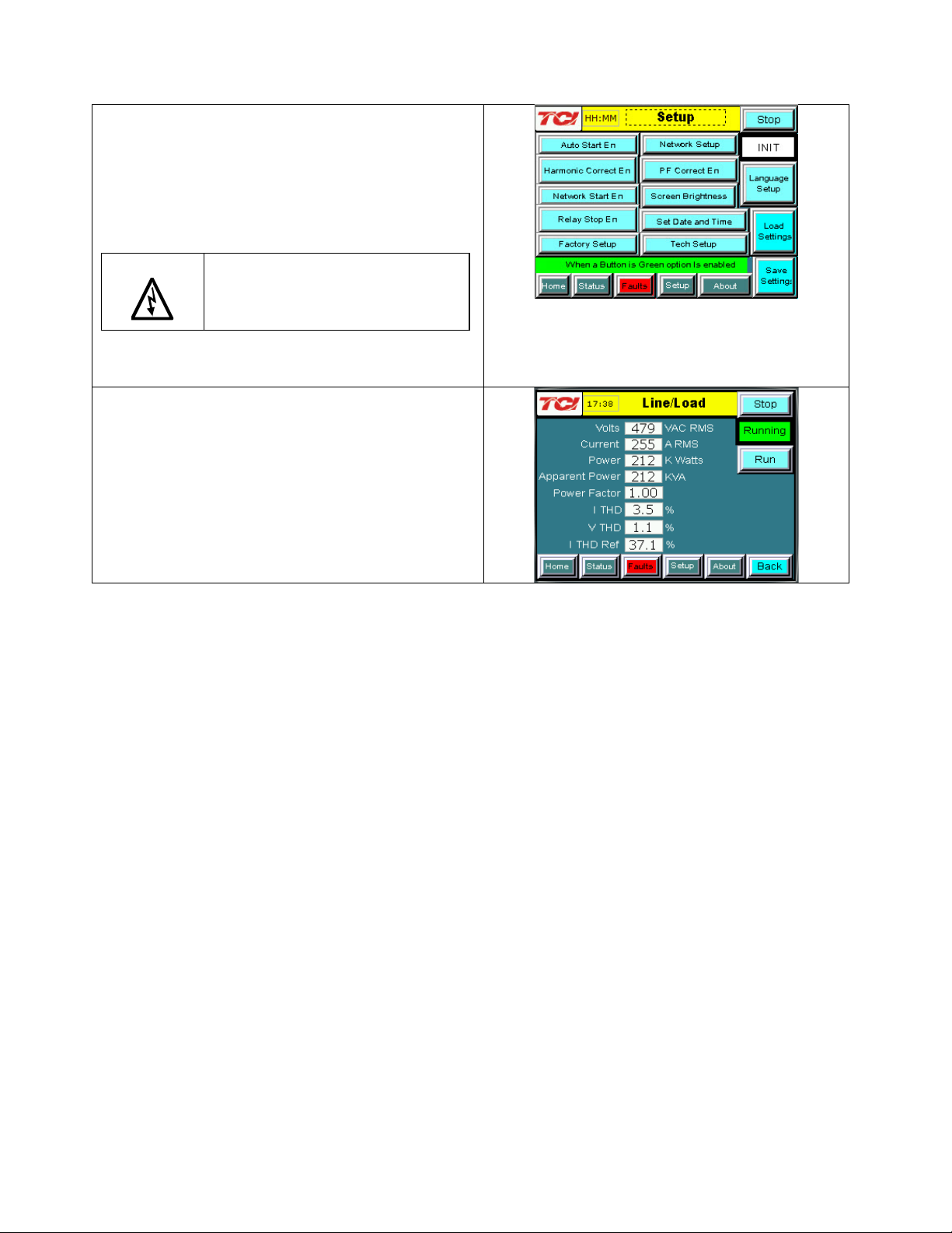
2) Converter check - 1
• Press “Setup” to navigate to Setup screen
• Ensure that “Auto Start En,” “Harmonic
Correct En,” and “PWR Fact Correct En”
buttons are off (blue color)
• If they are ON (green) press them to toggle to OFF
(blue)
• Press “Save Settings”
• Press “Status” to navigate to Status screen
• Press “Home” to navigate to Home screen
NOTE: Built In Sensor Wiring Error De tection
• The active filter has an automatic sensor wiring
error detection algorithm built in to the controls.
• If a sensor wiring error is detected please reference
the Sensor Error Auto Detection sectio n on page
93.
7
Page 8
Warning
3) Home screen check
• Compare “Freq” to expected line frequency
• Compare “Supply Voltage” to expected
line voltage
• “Current” expected to be zero because unit is not
running and CT inputs ar e shorted
• If status indicates a Fault, press “Stop” button to
reset condition
4) Status screen check
• Press “Status” to navigate to Status screen
• Compare “Volts” to expected line voltage
• Compare “Freq” to expected line frequency
• “Current” expected to be zero if unit is not running
and CT inputs are shorted
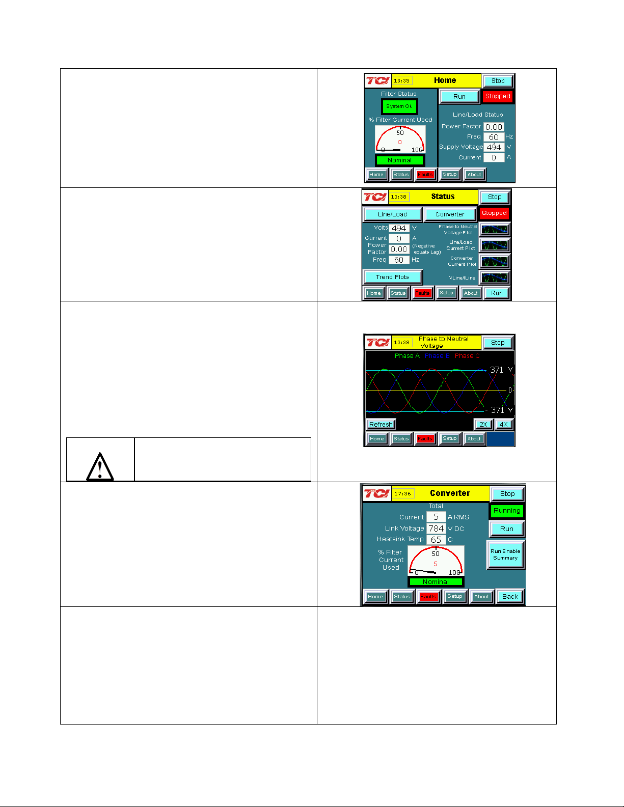
5) Phase rotation check
• Press “Phase to Neutral Voltage Plot”
• Check that the current p eaks follow the follo wing
sequence from left to right: Phase A (green), Phase
B (blue), Phase C (red)
• Equipment is phase rotation sensit ive, if phase
rotation is incorrect, power down unit and rewire
to adjust pha s e rotation by swapping two inco ming
phase connections
Improper operation will occur when input
voltage phase rotation is incorrec t.
6) Converter check - 2
• Press “Setup” to navigate to Setup screen
• Ensure that “Auto Start En,” “Harmonic
Correct En,” and “PWR Fact Correct En”
buttons are off (blue color)
• Press “Status” to navigate to Status screen
• Press “Run” to start unit operation
8
Page 9
from CTs connected to TB-1
Warning
7) Remove CT shorting bars
• Press “Stop” to turn off unit
• Disconnect power from cabinet
o Turn off the built in door breaker A ND
o Turn off the upstream feeder breaker
Lethal voltages may be present. Wait 5
minutes for DC bus voltage to drop to
safe levels.
Warning
Check for vol t age in cabinet with a
DMM before working inside cabinet.
• Open the cabinet door and remove shorting bars
8) Current polarity - 1
• Power up unit
• From Home screen press “Run” to turn on unit
• Press “Status” to navigate to Status screen
• Select “Vline/Iline” screen
• Note: Lightly loaded conditions (less than 20% CT
rating) wil l not have enough current to
show up on Iline plot
• Check that Phase A to Neutral voltage peak lines
up with Phas e A current (use zoom if necessary)
• Check that Phase C to Neutral voltage peak lines
up with Phas e C current
• Power system down and check CT inst allation
location and orientation if Phase A plots differ
significantly from Phase C plots
Warning
Improper operation and damage may
occur if CTs are installed incor r e c tly.
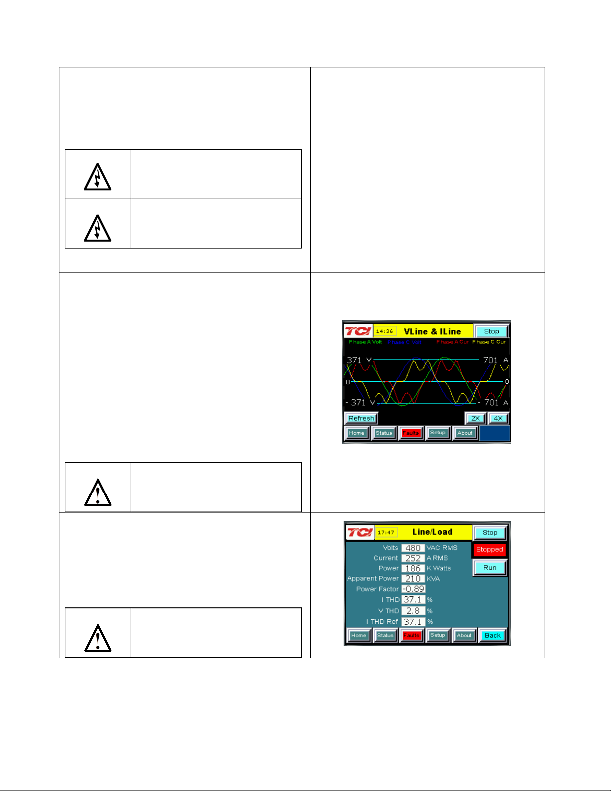
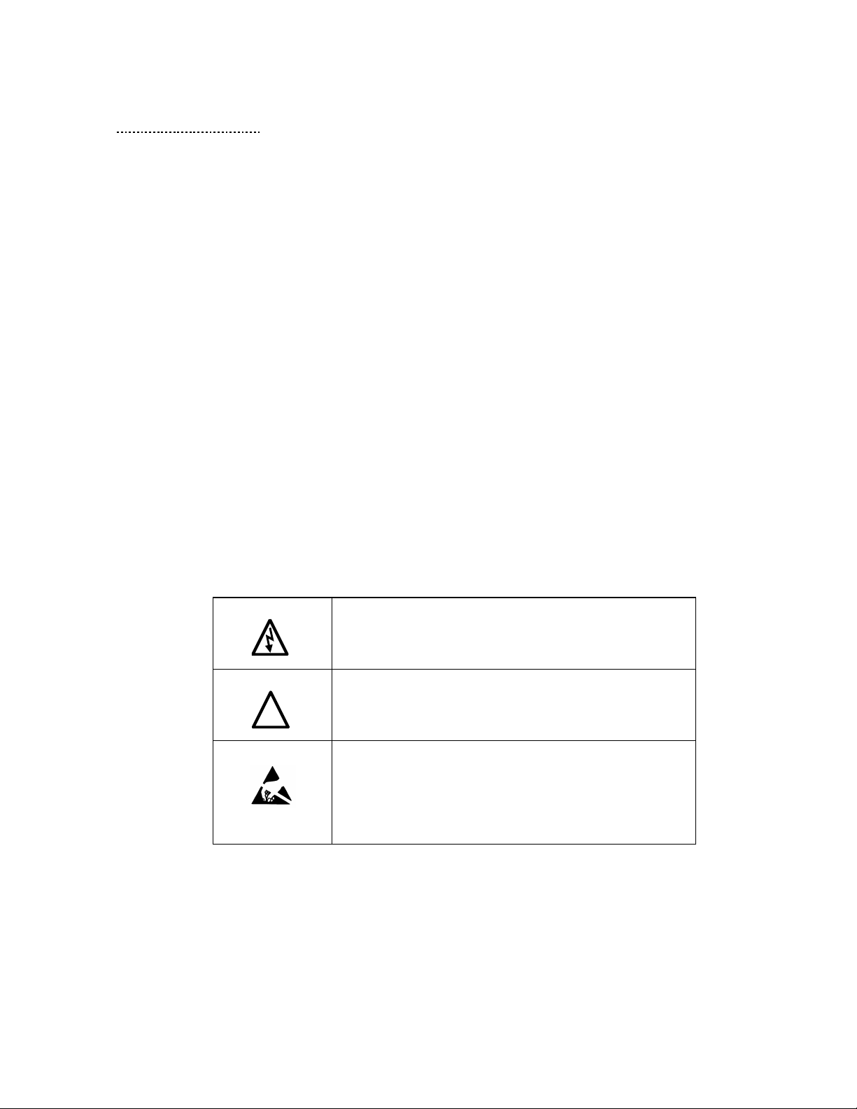
9) Current Polarity – 2
• Navigate to Status screen
• Navigate to Line/Load status
• Verify that “Volts,” “Current,” “Power,” “I THD,"
and “V THD” match expected values for the
power system
• If they do not, verify CTs are corr e c tly insta lle d
Warning
Improper operation and damage may
occur if CTs are installed incor r e c tly.
9
Page 10
Warning
• Let the unit come on automatically (about 30 s)
10) Final setup
• Press “Setup” to navigate to Setup screen
• Press “Harmonic Correct En” to enable
harmonic correction
• If unit is sized with sufficient cap a c ity to provide
power factor correction, press “PF Correct En”
• Press “Auto Start En” to enable Autostart
When Auto Start is enable d unit may
operate without operator input.
• Press “Save Settings” to save settings
and restart converter
11) Final check
• Navigate to Status screen
• Navigate to Line/Load status
• Note the corrected voltage, current, power
and THD
10
Page 11
!
■ Section 2
Safety Instructions
Overview
This section provides the safety instructions which must b e followed when installing, oper ating, and
servicing t he HarmonicGuard Active (HGA) filter. If negle cted, phys ical injur y or death ma y follow,
or damage may occur to the HGA filter or equipment connected to the HGA filter. The material in this
chapter must be read and understood before attempting any work on or with the product.
The HGA filter is intended to be connected to the bus or power cables where one or more loads are
connected. Three-phase power is connected to the input terminals of the unit and corrective current is
supplied to the system through the HGA filter in respo nse to the i nput signal being received from the
CTs connect ed to the moni tored bus. T he instructio ns, and pa rticularly t he safety ins tructions, fo r the
drives, motors, and any other related equipment must be read, understood, and followed when working
on any of the equipment.
Warnings and Cautions
This manual provides two types of safety instructions. Warnings are used to call attention to
instructions, which describe steps, which must be taken to avoid conditions, which can lead to a
serious fault condition, physical injury, or death.
Cautions are used to call attention to instructions that describe steps that must be taken to avoid
conditions that can lead to a malfunction and possible equipment damage.
Warnings
Readers are informed of situations that can result in serious physical injury and/or serious damage to
equipment wit h war ni n g stat e men t s mar ked wit h the fo ll o wi ng s ymb o ls:
Warning
Warning
Warning
Dangerous Voltage Wa rning: warns of situations in whic h a
high voltage can cause physical injury and/or damage
equipment. The text ne xt to this symbol describes ways to
avoid the danger.
General Warning: warns of situations that can cause physical
injury and/ or damage equipment by means othe r than
electrical. The text next to this symbol describes ways to avoid
the danger.
Many electronic components located within the filter are
sensitive to static electricity. Voltages imperceptible to human
touch can reduce the life, and affect performance, or
completely destroy sensitive electronic devices. Use proper
electrostatic discharge (ESD) procedur es when servic ing the
filter and its circuit boards.
11
Page 12
Warning
Warning
!
!
!
!
Cautions
Readers are informed of situations that can lead to a malfunction and possible equipment damage with
caution statements:
Caution
Warning
Warning
Warning
General Caution: Identifies situations that can lead to a malfunction and possible equipment damage.
The text describes ways to avo id the situation.
General S afety Ins truct ions
These safety instructions are intended for all work on the HGA filter. Additional safety instructions are
provided at appropriate points on other sections of this manual.
Be sure to read, understand, and follow all safety instructions.
Only qualified electricians should carry out all electrical installation and maintenance work on the
HGA filter.
All wiring must be in accordance with the National Electrical Code (NEC) and/or any other codes that
apply to the installation site.
Disconnect all power before working on the equipment.
Do not attempt any work on a powered HGA filter.
Warning
Warning
The HGA filter drive, motor, and other connected equipment must be properly grounded.
The HGA filter may receive power from two or more sources.
Three-phase power is connected to the main input terminals of the HGA filter.
All of these sources of power must be disconnected before working on the HGA filter.
After switching off the power, always allow 5 minutes for the capacitors in the HGA filter and in the
drive to di s charge before working on the HGA filter, the drive, the motor, or the connecting wiring. It
is good practice to check with a voltmeter to make sure that all sources of power have been
disconnected and that all capacitors have discharged before begin ni ng wor k.
12
Page 13

General T erminology
Throughou t this manual, many d ifferent terms are used. A list of so me typical terms ca n be found
below. These are provided in order to assist with the overall understanding of the manual. Please feel
free to contact TCI directly if there are any questions regarding any portion of this manual.
HarmonicGuard Active Filter - TCI’s brand name for a real ti me filter that mitigates harmonic s while
also maintaining near unity power factor. An Active Har monic Filter is any piece of equipment that
actively moni to rs and chan ges the incoming AC line current.
HGA – The term commonly used in place of the entire brand name of HarmonicGuard Active filter.
Active Harmonic Filter - An active harmonic filter is a piece of equipment that reads the incoming
voltage and curre nt and i nje cts curr ent wavefor ms tha t canc el di storti on. T his ter m is co mmonl y used
in place of the entire brand name of HarmonicGuard Active filter.
Bus-Applied Filter – A shunt device connected in parallel to the load. This is an active filter designed
to mitigate the harmonics associa ted with multiple load s. The filter is dir ectly co nnected to a main bus
as can be found in a typical Motor Control Center. The filter is sized for the amount of corrective
current needed to be injected to cancel the offending harmonics. A Digital Signal Processor (DSP)
pulse width modulated controller is used for switching Insulated Gate Bip olar Transistor (IGBT) in
order to cancel the harmonic s .
Power Converter - The power converter is the digital filter module of the HarmonicGuard Active filter.
Non-Linear Load Input Line Inductor – The three phase line reactor connected at the input of an
adjustable frequency drive or other non-linear load.
Converter Inductor – The three phase inductor maintains a unifor m air gap to give high ly consistent
and predictable inductance. These inductors are connected to the inverter which buffers the inverter
output from the analog portion o f the filter , the source, and connected drives.
Current Transfor mer (CT) – The device that monitors t he incoming AC curre nt waveform typicall y
sized to handle the total connected load.
13
Page 14
o
o
o
o
o
o
o
o
!
■ Section 3
Introduction
Thank you fo r selecting TCI’s HarmonicGuard Active filter. TCI has produced this filter for use in
variable speed drive and non-linear load applications that require input power line harmonic current
reduction and power factor correction. This manual describes how to install, operate, and maintain the
HarmonicGuard Active filter.
Intended Audience
This manual is intended for use by all personnel responsible for the installation, operation, and
maintenance of the HarmonicGuard Active filter . Such personnel are expected to have knowledge of
electrical wiring practices, electronic components, and electrical schematic symbols.
Additiona l Infor mation
Caution
This manual pro vid es gene ra l i nfo r mati o n desc ri b i ng yo ur H GA filter. Be sure to carefully review the
more specific information that is provided by the drawings shipped with the unit. Information
provided by the drawings takes precedence over the information provided in this manual.
The ratings, dimensions, and weights given in this manual are approximate and s hould not be used for
any purpose requiring exact data. Contact the factory in situations where certified data is required. All
data is subject to change without notice.
Installation Checklist
The following are the key points to be followed for a successful installation. These points are
explained in detail in the following sections of this manual.
Make sure that the installation location will not be exposed to direct sunlight, excessive
vibration, corrosive or combus tible airborne contaminants, excessive d ir t, or liquids.
Select a mounting area that will allow adequate cooling air and maintenance access.
Make sure that all wiring conforms to the requirements of the National Electric Code
(NEC) and/or other applicable electrical codes.
Connect the HGA filter equipment-grounding lug to the system ground of t he premises
wiring system. Use a properly sized grounding conductor.
Connect three-phase power to the input terminals o f the HGA filter, L1, L2, & L3.
Ensure that the CTs are properly installed and connected to the proper terminals inside
the HGA filter (see CT Installation section of IOM Manual).
Check ever ything thor oughly before appl yi ng power to t he equipment.
Check the panel and the inside of the enclosure for any foreign objects, dirt, or
loose hardware.
14
Page 15

Receivi ng Inspection and Storage
Receiving Inspection
The HarmonicGuard Active filter ha s been thoro ughly i nspecte d and fu nctiona lly te sted at the fac tory
and carefully packaged for shipment. When you receive the unit, you should immediately inspect the
shipping container and report any damage to the carrier that delivered the unit. Verify that the part
number of the unit you received is the same as the part number listed on your purchase order.
TCI Limited Warranty Policy
TCI, LLC (“TCI”) warrants to the original purchaser only that its products will be free from defects in
materials and workmanship under normal use and service for a period originating on the date of
shipment from TCI and expiring after one (1) year of useful service, not to exceed eighteen (18)
months from the date of shipment.
The foregoing limited warranty is TCI’s sole warranty with respect to its products and TCI makes no
other warranty, representation or promise as to the quality or performance of TCI’s products. THIS
EXPRESS LIMITED WARRANTY IS GIVEN IN LIEU OF AND EXCLUDES ANY AND ALL
EXPRESSED OR IMPLIED WARRANTIES INCLUDING, WITHOUT LIMITATION, ANY
IMPLIED WARRANTY OF MERCHANTABILITY OR FITNESS FOR A PARTICULAR
PURPOSE.
This warranty shall not apply if the product wa s :
a) Altered or repaired by anyone other than TCI;
b) Applied or used for situations other than those originally specified; or
c) Subjected to negligence, accident, or damage by circumstances beyond TCI’s control,
including but not limited to, imprope r storage, installation, operation or maintenance.
If, within the warranty period, any product shall be found in TCI’s reasonable judgment to be
defective, TCI’s liability and the Buyer’s exclusive remedy under this warranty is expressly limited, at
TCI’s option, to (i) repair or replacement of that product, or (ii) return of the product and refund of the
purchase price. Such remedy shall be Buyer’s sole and exclusive remedy. TCI SHALL NOT, IN ANY
EVENT, BE LIABLE FOR INCIDENTAL DAMAGES OR FOR CONSEQUENTIAL DAMAGES
INCLUDING, BUT NOT LIMITED TO, LOSS OF INCOME, LOSS OF TIME, LOST SALES,
INJURY TO PERSONAL PROPERTY, LIABILITY BUYER INCURS WIT H RESPECT TO ANY
OTHER PERSON, LOSS OF USE OF THE PRODUCT OR FOR ANY OTHER TYPE OR FORM
OF CONSEQUENTIAL DAMAGE OR ECONOMIC LOSS.
The foregoing warranties do not cover reimbursement for removal, transportation, reinstallation, or any
other expenses that may be incurred in connection with the repair or replacement of the TCI product.
The employees and sales agents of TCI are not authorized to make additional warranties about TCI’s
products. TCI’s employees and sales agents oral statements do not c onstitute warranties, shall not be
relied upon by the Buyer and are not part of any contract for sale. All warranties of TCI embodied in
this writing and no other warranties are given beyond those set fo rth herein.
TCI will not accept the return of any prod uct without its prior written approval. Please co nsult TCI
Customer Service for instructions on the Return Authorization Procedure.
Storage Instructions
If the HarmonicGuar d Active filter is to be stored before use , be sure that it is stored in a location that
conforms to published s torage h umidity a nd temperat ure sp ecificatio ns stated in this manual. Sto re the
unit in its original pac kaging.
Long-Term Storage
In the case of long-term storage, defined as any period greater than eighteen (18) months, TCI
Technical Support must be contacted prior to applying power.
15
Page 16

Product Descript ion
HarmonicGuard Active filter
The HarmonicGuard Active filter is an active harmonic filter designed and developed by TCI to relieve
the power distribution system o f the issues associated with harmonic currents that flow within the
power distribution network caused by non-linear loads. The typical configuration can be found in
Figure 3.1.
The topology of the bus-applied (three phase, three wire) HGA consists of major components or
modules:
Component 1 is mad e up of two current transformers (CTs) installed on phases A and C of the AC bus
that is to be acted upon by the filter. The purpose of the CTs are to supply information to the HGA
regarding t he integrity of the composite AC bus c urrent with rega rd to the distor tion (non-sinusoidal
waveform) and displacement power factor relative to the AC bus voltage. These signals will result in
the HGA inje cting currents th at will return the AC line current to near sinusoidal s hape and at unit y
power factor. Note that the CTs are located outside the HGA enclosure.
Component 2 is the HGA input circuit breaker (optional) . This is provided to protect the HGA for
destructi ve ove r cur rent c ond itio ns if a malfu nctio n oc curs withi n the HGA circ uitry. It also p rovides a
convenient disconnect means and field wiring point for the installer of the filter equipment.
Components 3 and 4 are the high freq uency co nverter i nductors . These i nductors provid e the prop er
inductance to the power converter.
Component 5 is the power electronic converter module. The Power converter module (PCM) is the
heart of the HarmonicGuard Active filter and is what differentiates the HGA from other types of
harmonic mitigation. The PCM provides several highly complex electronic functions controlled by the
on board DSP controller. The PCM continuously senses the AC bus line voltage and currents,
processes the information at “nearly real time” by means of the instructions resident within the DSP
program code, properly controls the six IGBT’s to operate in a safe manner that injects current into the
AC bus grid that ensures the AC bus current is sinusoidal and near unity power factor. Power converter
contains a pre-charge circuit which consists of two SCRS and two pre-charging resistances which
control the inrush current.
16
Page 17
Filter Configuration
Figure 3.1 – Typi cal Configur ation of the HarmonicGuard Active filter
*This drawing is for gene ral reference only. Us e the drawings supplied with the unit for inst allation.
17
Page 18
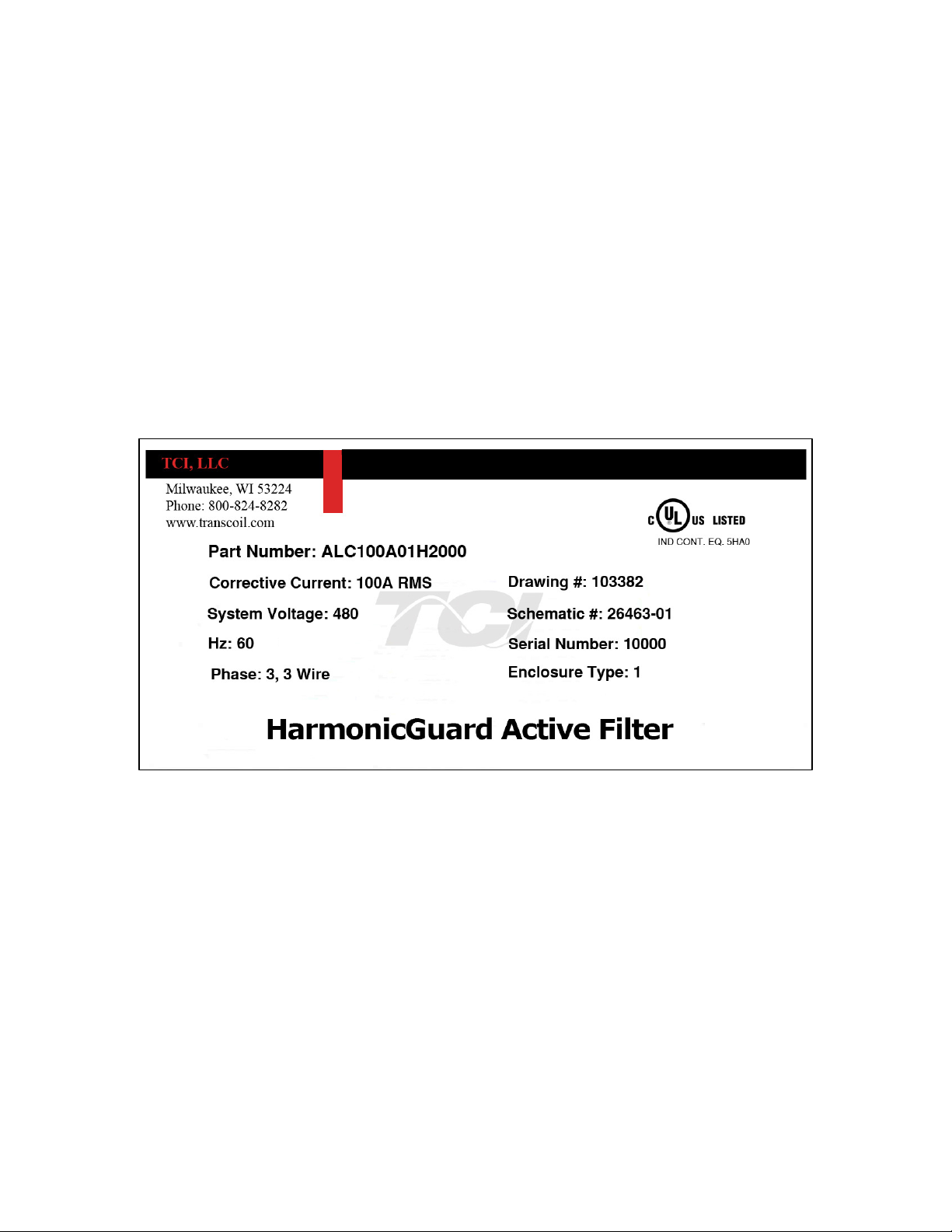
Nameplate Data
Figure 3.2 shows a typical HarmonicGuard Active filter nameplate. The following information is
marked on the nameplate:
Part number : encoding is explaine d on the following page
Corrective Current: The maximum amount of RMS Corrective Current the unit can deliver.
System Voltage: the rated 3-phase line voltage (RMS volts)
Hz: the rated frequency (60 Hz)
Phase: 3, 3 Wire – The HGA is designed for use with only 3 wire systems with balanced 3-
phase voltage sour ce.
Drawing #: outline and mounting dimension drawing number
Schematic #: schematic diagra m drawing number
Serial #: fo r unit tracking purposes
Enclosure Type: Open, UL Type 1, UL Type 3R
Figure 3.2 – Typical HarmonicGuar d Ac tive filter Nameplate
18
Page 19
ALC 100 A 01
H 00
00
ALC
Prefix
Current Rating
Voltage Rating
A= 480
Filter Enclosure
00 = Open Chassis
01 = UL Type 1
Package Option
Circuit Breaker
H = Interface Module
10=ABB 22kA
2
0=ABB 100kA
30=A-B 25kA 40=A-B 65kA
60=Eaton 65kA 7
0=Eaton 100kA
80=Square D 18kA 90=Square D 65kA
00=No breaker 01=ABB 65kA
Reserved for custom options to be
defined as needed, each position can
use 0 thru 9.
Default option is 00.
50, 100, 200
Part Number Encoding
Figure 3.3 identifies the significance of each character in the HarmonicGuard Active filter part
number. An example of a completed part number would be ALC100A01H2000. This designates an
enclosed HarmonicGuard Active filter that i s rated for 100 amps, 480 volts, and has an HMI Interface
Module Package.
HGA Part Numbering System – 480V Open and T ype 1
Temperature: 40° C
Current: 50, 100, 200
Voltage: 480
Enclosure: Open Chass is or UL Type 1
Figure 3.3 – Harmoni cGuard A ctive filte r par t number encoding
19
Page 20
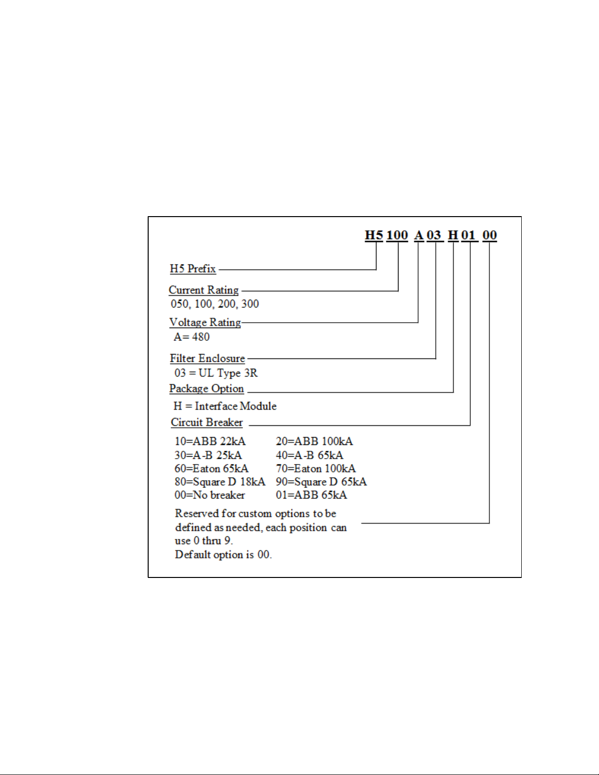
Figure 3.4 identifies the significance of each character in the HarmonicGuard Active filter part
number. An example of a completed part number would be H5100A03H4000. This designates an
enclosed HarmonicGuard Active filter that is rated for 100 amps, 480 volts, and has an HMI Interface
Module Package.
HGA Part Numbering System – 480V 3R
Temperature: 40° C Current: 50, 100, 200, 300 Voltage: 480 Enclosure: UL Type 3R
Figure 3.4 – Harmoni cGuard A ctive filte r Part number Encoding
20
Page 21
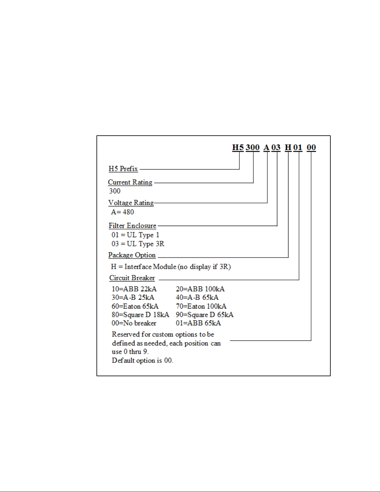
Figure 3.5 identifies the significance of each character in the HarmonicGuard Active filter part
number. An example of a completed part number would be H5300A00H1000. This designates an
enclosed HarmonicGuard Active filter that i s rated for 300 amps, 480 volts, and has an HMI Interface
Module Package.
HGA Part Numbering System – 480V 300A
Temperature: 40° C
Current: 300
Voltage: 480
Enclosure: U L Type 1 or UL Type 3R
Figure 3.5 – Harmoni cGuard A ctive filte r Part number Encoding
21
Page 22
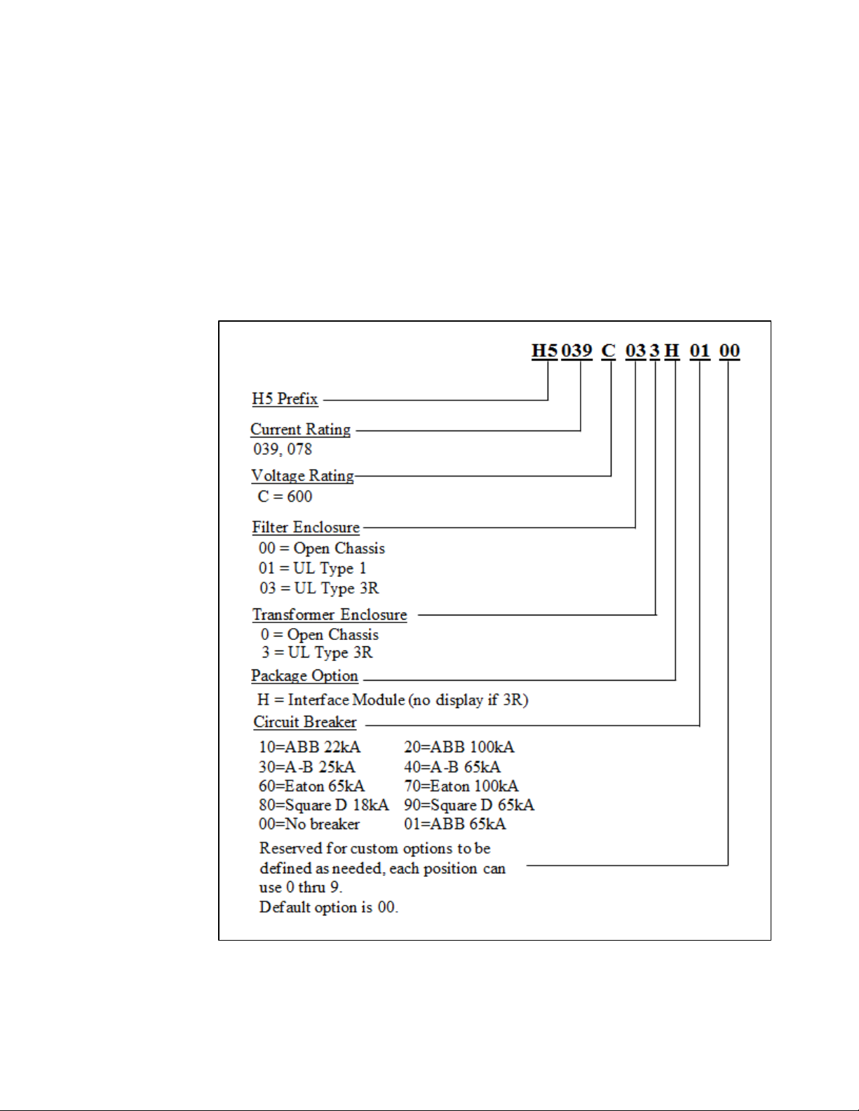
Figure 3.6 identifies the significance of each character in the HarmonicGuard Active filter part
number. An example of a completed part number would be H5039C033H0100. This desig nates an
enclosed Har monicGuard Active filter that is rated for 39 amps, 600 volts, and has an H MI Interface
Module Package.
HGA Part Numbering System – 600V
Temperature: 40° C
Current: 39, 78
Voltage: 600
Enclosure: Open Chassis, UL Type 1 or UL Type 3R
Figure 3.6 – Harmoni cGua rd Active Part number Encoding
22
Page 23
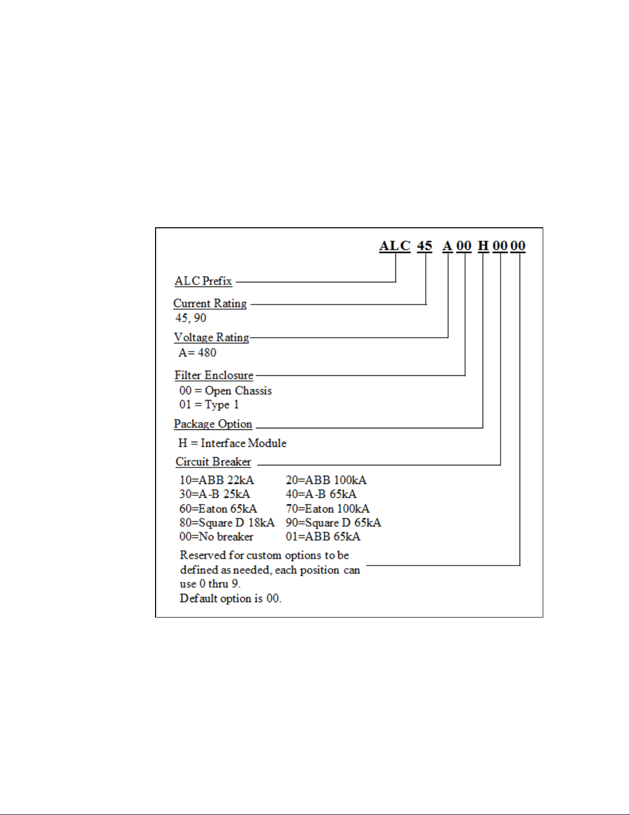
Figure 3.7 identifies the significance of each character in the HarmonicGuard Active filter part
number. An example of a completed part number would be ALC45A01H10. This designates an
enclosed HarmonicGuard Active filter that is rated for 45 amps, 480 volts, and has an HMI Interface
Module Package.
HGA Part Numbering System – 480V Open & Type 1 (50° C)
Temperature: 50° C Current: 45, 90 Voltage: 480 Enclosure: Open Chass is or UL Type 1
Figure 3.7 – Harmoni cGuard A ctive filte r Part number Encoding
23
Page 24
CM
Communications
39, 45, 50, 78, 90, 100,
200, 300
A
Voltage rating of 480V
C
Voltage rating of 600V
00
Modbus RTU over RS485
01
Ethernet/IP
Dimensions Inch (cm)
39
2676
167 (75.8)
56 (142.2)
17 (43.2)
14.18 (36.6)
45 & 50
2676
167 (75.8)
56 (142.2)
17 (43.2)
14.18 (36.6)
78
3500
167 (75.8)
56 (142.2)
17 (43.2)
14.18 (36.6)
90 & 100
3500
167 (75.8)
56 (142.2)
17 (43.2)
14.18 (36.6)
200
7000
340 (154.22)
57.97 (147.25)
32 (81.28)
14.18 (36.6)
Dimensions Inch (cm)
39
2676
254 (115.2)
60.15 (152.8)
17.57 (44.5)
*16.4 (41.7)
50
2676
254 (115.2)
60.15 (152.8)
17.57 (44.5)
*16.4 (41.7)
78
3500
254 (115.2)
60.15 (152.8)
17.57 (44.5)
*16.4 (41.7)
100
3500
254 (115.2)
60.15 (152.8)
17.57 (44.5)
*16.4 (41.7)
200
7000
480 (217.72)
64.17 (163)
32.62 (82.86)
*17.2 (43.7)
300
10500
1042.4 (472.9)
84.20 (213.9)
63.3 (160.8)
*23.9 (60.7)
*Add Two Inches for Disconnect/Circuit Breaker Handle,
Communications Part Numbering
Table 3.1 bel ow shows the HGA part numbering with the communications part numbers. The base
communications unit is CM100A00 which has both the HMI and Modbus.
Table 3.1 – Communcation Part Numbering
Options Descriptions
Amp rating
A, C
00, 01
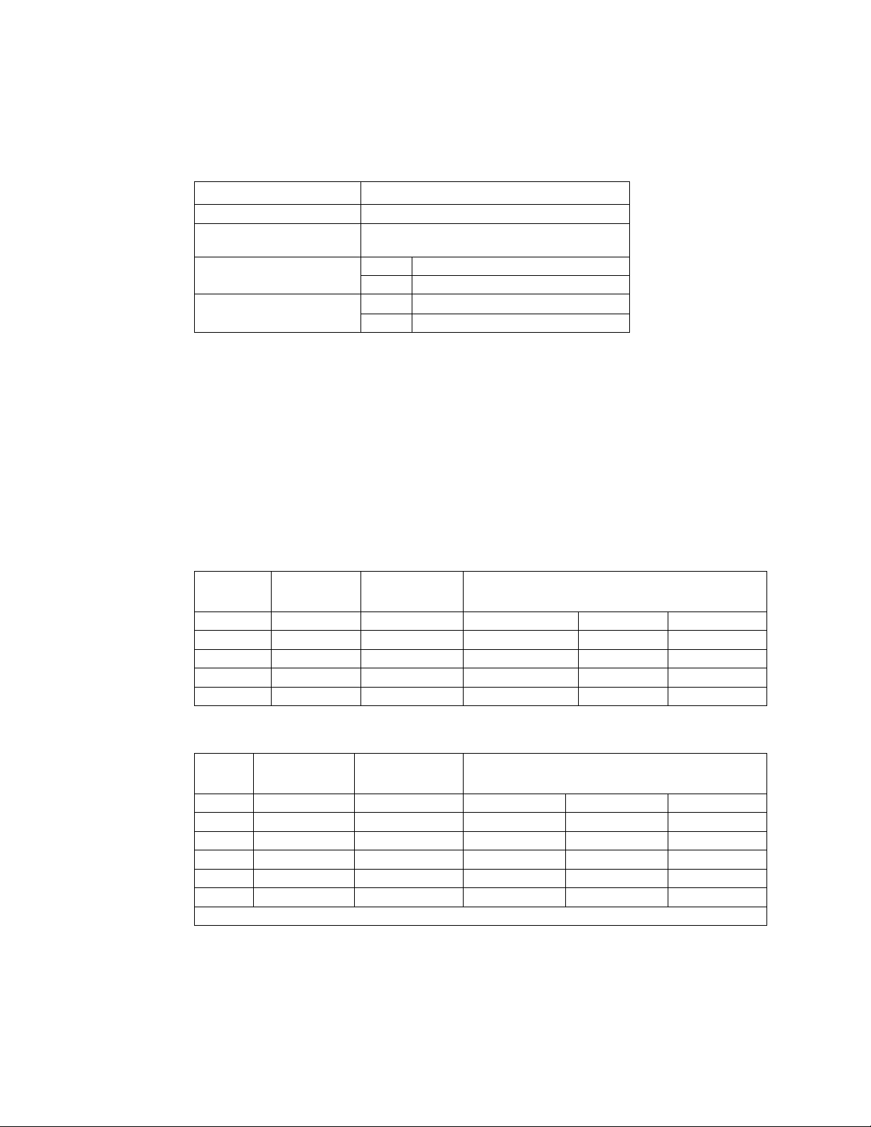
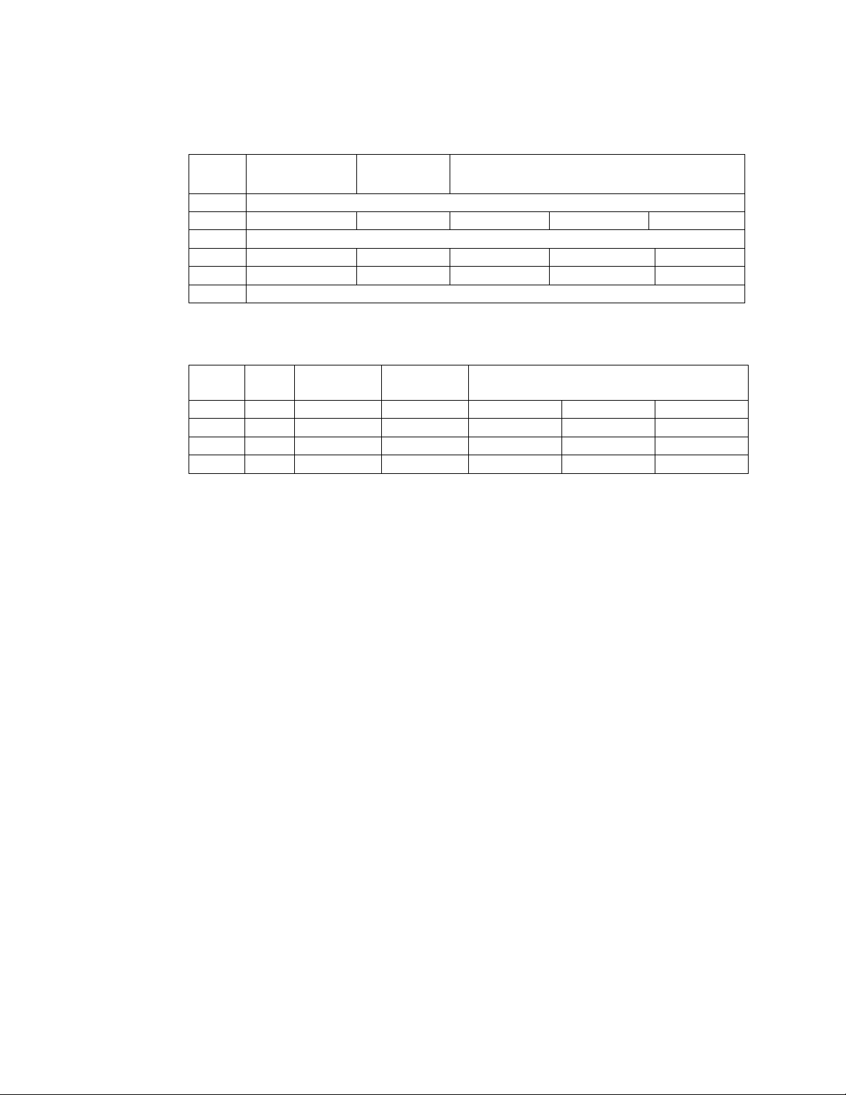
Standard Product Ratings and Dimension Tables
The following tables list the ratings and dimensions of the standard HarmonicGuard Active filter
models. See drawing at the end of this manual.
• Table 3.2 – Open Chassis
• Table 3.3 – UL Type 1 Enclosed
• Table 3.4 – UL Type 3R Enclosed
• Table 3.5 – 600V Open and Type 3R
Table 3.2 – Open Chassis
Amps
Heat Loss
(watts)
Weight lbs.
(kg)
H x W x D
Table 3.3 – UL Type 1 Enclosed
Amps
24
Heat Loss
(watts)
Weight lbs.
(kg)
H x W x D
Page 25
Dimensions Inch (cm)
39
Consult Factory
50
3176
371 (168.3)
80.00 (203.2)
32.00 (81.3)
25.00 (63.5)
78
Consult Factory
100
3500
371 (168.3)
80.00 (203.2)
32.00 (81.3)
25.00 (63.5)
200
7000
1040 (472)
80.00 (203.2)
57.00 (144.78)
25.00 (63.5)
300
Consult Factory
Heat Loss
(watts)
Weight
lbs. (kg)
Dimensions Inch (cm)
H x W x D
39
Open
345
180 (81.7)
16.00 (40.7)
19.50 (49.6)
12.20 (31)
78
Open
740
180 (81.7)
16.00 (40.7)
19.50 (49.6)
12.20 (31)
39
3R
345
270 (122.5)
24.90 (63.3)
24.40 (62)
20.80 (52.9)
78
3R
740
270 (122.5)
24.90 (63.3)
24.40 (62)
20.80 (52.9)
Table 3.4 – UL Type 3R Enclosed
Amps
HeatLoss
(watts)
Weight lbs.
(kg)
H x W x D
Table 3.5 – Transformer for 600V units – Open and Type 3 R
Amps Encl.
25
Page 26
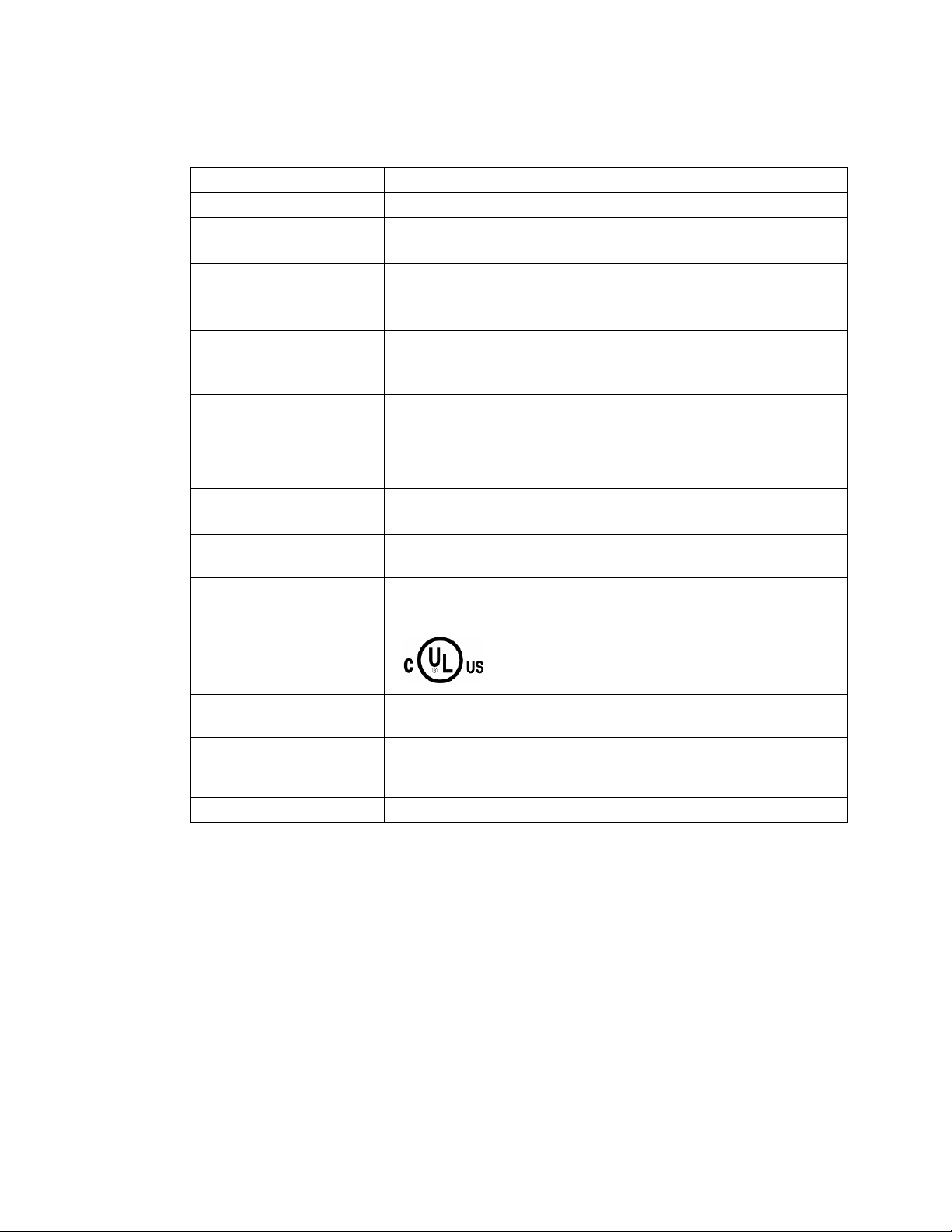
Table 3.6 – HarmonicGuard Ac tive filter Technical Specifications
Voltage ratings 480V, 3 phase, 60 Hz, three wire systems
Phase Sequence Positive phase rotation: A-B-C (or L1-L2-L3)
Load types
Current ratings See Ratings in Standard Product Rating and Dimensi ons tables.
Maximum elevation
Maximum Amb ient
operating temperature
Minimum Amb ie n t
operating temperature
Ambient storage temperature
Maximum humi d it y,
operating or storage
Enclosure options
Agency approvals or
certifications
3-phase diode bridge rectifier loads such as PWM AC drives
*3-phase controlled rectifier (SCR or thyristor) loads such as DC drives
1,000 meters (3,280 feet) For every 100 meters (328 feet) over 1,000,
de-rate by 1%. Maximum elevation is 2,000 meters (6,560 feet).
All units 40°C (104°F) except 45 & 90 amp open chassis units rated for
50°C (122°F) surrounding air. Product must be equipped with special
cooling provisions for operation above this temperature.
0°C (32°F) for open chassis and Type 1 enclosures.
-20°C (-4°F) for Type 3R enclosures.
Product must be equipped with special heating provisions for operation
below this temperature.
-20°C to 60°C for Open Chassis and UL Type 1
-40°C to 60°Cfor UL Type 3R
95%, non-condensing
Standard: Open Chassis and UL Type 1 enclosed, UL Type 3R enclosed
Contact TCI Technical Support for other enclosure options.
UL and cUL Listed
Electronic overload / over
current protection
Over current protection:
*
Status indication LEDs Numerous LED indicators on converter unit
P
*Please consult TCI regarding optimum filter performance when applied to DC drives.
Factory calibrated processor controlled electronic over current fault, and
over load.
All units have internal circuit bre a ker for protection of the converter
section of the HGA. The customer must supply branch circuit
protection.
26
Page 27
!
■ Section 4
Pre-installation Planning
Verify th e A pplicat ion
HGA Ratings
Make sure that the HarmonicGuard Active filter is correct for the application and sized for load. The
voltage ratings of the HGA m us t match the input voltage rating of t he connected AC bus.
Select a Suitable Location
Environment
Locating the HarmonicGuard Active filter in a suitable environment will help assure proper
performance and a normal op erating life. Re fer to t he enviro nmental spec ifications listed in Table 3.6,
marked on the unit's nameplate and/or noted on the drawings furnished with the unit.
Warning
Unless specifically labeled as approved for such use, this equipment is not suitable for use in an
explosive atmosphere or in a "Hazardous (Classified) Location" as defined in article 500 of the
National Electrical Code (NEC).
UL Type 1 and open chassis units must be installed in an area where it will not be exposed:
• Direct sunlight
• Rain or dripping liquids
• Corrosive liquids or gasses
• Explosive or combustible gases or dust
• Excessive airborne dirt and dust (Pollution Degree 2, according to EN50178 and UL508)
• Excessive vibration [0.152 mm (0.006 in.) displacement, 1G peak]
Please note that custom enclosure options may vary available installation areas.
Working Space
Provide sufficient access and working space around the unit to permit ready and safe installation,
operation and maintenance. Make sure that the installation conforms to all working space and
clearance requirements of the National Electrical Code (NEC) and/or any other applicable codes.
Provide sufficient uno bstructed space to allow cooling air to flow through the unit.
Mounting an Open Chassis Unit
If you are mount in g an o pe n c has sis unit in your o wn enc los ure , yo u mu st p rovi de a n e ncl osur e tha t i s
adequately sized and ventilated sufficiently to p revent o verheati ng. Re fer to Table 3.2 for dimensions
and heat loss that is dissipated b y the HGA. The maximum ambient temperature should not exceed 40°
C (104° F). The 45 and 90 amp open chassis units have an ambient surrounding air temperature of
50ºC (122ºF).
Cooling Diagrams
Please see Figures 4.1 and 4.2 for cooling diagrams of the HGA.
27
Page 28
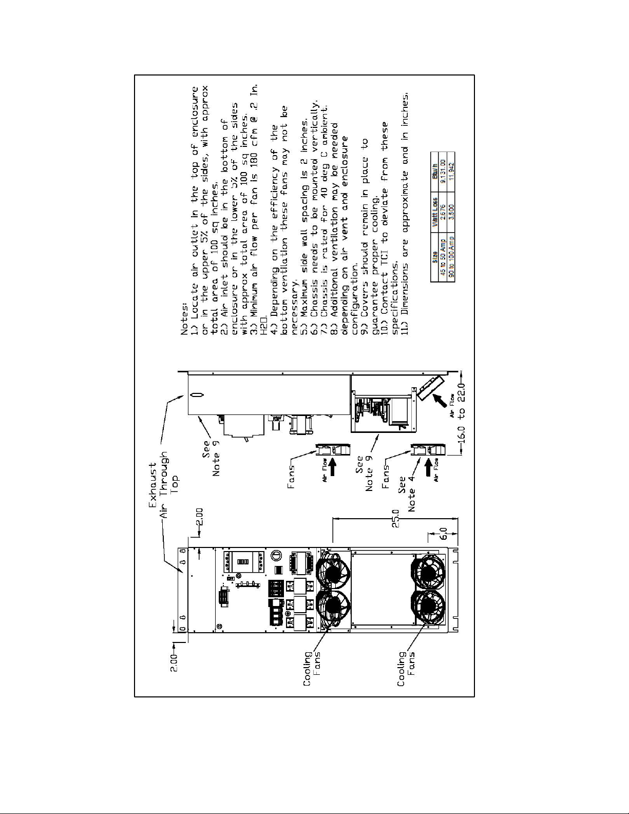
Figure 4.1 – Cooling Diagram for 39, 45, 78, 90 and 100 amp uni ts
28
Page 29
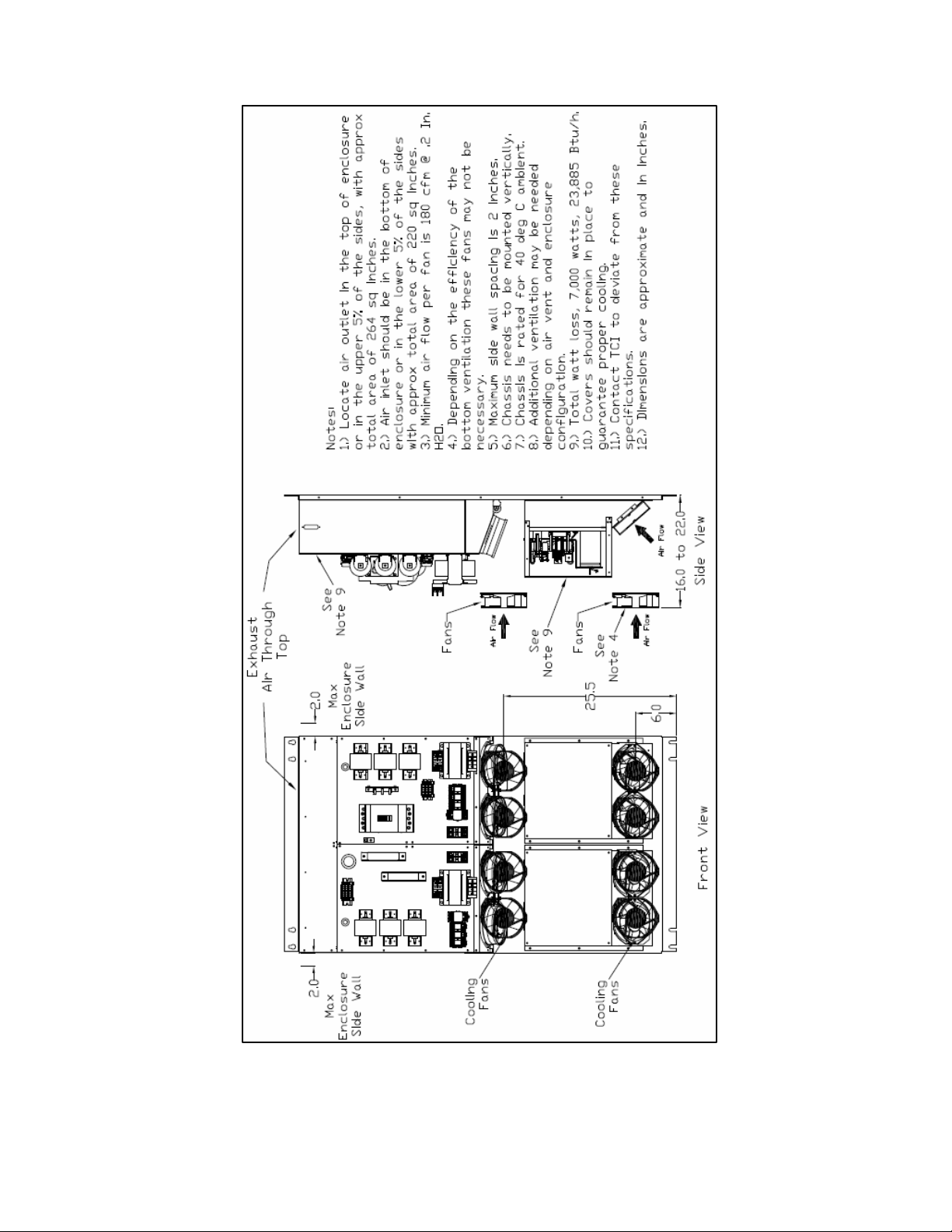
Figure 4.2 – Co oling Dia gram for 200 amp units
29
Page 30
Ground Lug
Power Terminals
(Nm)
IC
(Nm)
39 & 78 Amp
14 AWG - 2/0
120 (13.6)
22 kA
14 - 1/0 AWG
70 (7.9)
39 & 78 Amp
14 AWG - 2/0
120 (13.6)
65 kA
4 AWG – 350 MCM
250 (28.2)
70 (7.9)
274 (31)
274 (31)
25 to
100 kA
Two 3/0 AWG – 250
MCM
274 (31)
45, 50, 100, 200
Amp
!
Installa tion Guidelines
Mounting
The HGA must be mounted vertically on a smooth, solid surface, free from heat, dampness, and
condensation.
Wiring
Cable Entry Locations
The enclosed HarmonicGuard Active filters are not provided with enclosure wiring knockouts,
however, a removable wire entry plate is provided. A selection can be made at the time of installation.
Typical or recommended cable entry locations are shown in the drawings shipped with the unit.
Caution
Refer to circuit breaker section on page 50.
Field Wiring Connection Terminals
Compression type terminals are provided for all field wiring connections. The wire size (75° C copper)
capacity ranges and tightening torque for the grounding and power terminals are listed in Table 4.1a
and 4.1b. Refer also to the drawings and other information shipped with the unit. A disconnecting
means is the responsibility of the customer.
Table 4.1a – Exa mple Power Termi nal Wire Size Ca pacity Ra nge and Tightenin g Torque for ABB Circuit Breakers
Filter Size
45 & 50 Amp 14 AWG - 2/0 120 (13.6) 22 kA 14 - 1/0 AWG 70 (7.9)
39 & 78 Amp 14 AWG - 2/0 120 (13.6) 25 kA 2 - 4/0 AWG 250 (28.2)
100 Amp 14 AWG - 2/0 120 (13.6) 25 kA 4 AWG – 300 MCM 200 (22.6)
Wire Size
Torque In-lbs
Breaker
Wire Size
Torque In-lbs
45 & 50 Amp 14 AWG - 2/0 120 (13.6) 65 kA 14 - 1/0 AWG
100 Amp 14 AWG – 2/0 120 (13.6) 65 kA 6 AWG – 350 MCM
39 to 100 Amp 14 AWG – 2/0 120 (13.6) 100 kA 6 AWG – 350 MCM
200 Amp Two 6 AWG – 250 MCM 275 (31.1)
300 Amp Consult Factory
39 & 78 Amp Control Terminals Wire Size 30 to 12 AW G Torque 4.4 in-lb. (.5 Nm)
Note: The values in this table are representative of ABB switch gear. For other manufacturer’s switch gear please contact
TCI.
Control Terminals Wire Size 28 to 14 AWG Torque 4.4 in-lb. (.5 Nm)
30
Page 31

Ground Lug
Power Terminals
Wire Size
Torque In-lbs (Nm)
Breaker IC
Wire Size
Torque In-lbs (Nm)
39 to 100 Amp
14 AWG – 2/0
120 (13.6)
25 to 100 kA
14 – 2/0 AWG
180 (20.3)
25 to 100 kA
None
Control Terminals Wire Size 28 to 14 AWG Torque 4.4 in-lb (0.5 Nm)
!
Table 4.1b – Power Termi nal Wire Size (wi thout brea ker) Ca pacity Range and Tightenin g Torque
Chassis Size
150 to 200 Amp 14 AWG – 2/0 120 (13.6)
150 to 200 Amp 14 AWG – 2/0 120 (13.6)
Caution
Use copper wire that is appropriate for the voltage and current rating of the equipment. The wire
selection must conform to the requirements of the National Electrical Code and/or other applicable
electrical codes.
Use wire with an insulation temper ature rati ng of 75°C or higher.
Connection Diagram
Figure 4.3 sho ws the typical wiring connections between the models of the HGA and the load. Refer
to the drawings furnished with the unit for more specific information.
• The input 3-p hase AC voltage source must be connected in a positive ABC phase rotation
from L1-L2-L3 for correct unit operation.
6 AWG – 350 MCM 274 (31)
6 AWG – 350 MCM 274 (31)
Figure 4.3 – Typical Load Connection Di agram
Notes:
1.) Wiring should be 75°C or higher insulated copper, with the appropriate voltage and current rating.
2.) Chassis ground must be connected to the ground of the premises wiring system, in accordance
with NEC and local codes. Connection must be made using a wire conductor.
3.) Terminal TB-I & J25 wire range is 30-12 AWG, tightening torque is 4.4 IN-LB (0.5 NM).
4.) Operating current transformers with the secondary winding open can result in a high voltage
across the secondary terminals which may be dangerous to personnel or equipment.
31
Page 32

39
250:5
3000:5
50
250:5
3000:5
79
250:5
3000:5
100
250:5
3000:5
200
750:5
3000:5
300
750:5
5000:5
!
Current Transformer Installation
For accurate sensing of the load it is important that the load sensing current transformers are properly
installed.
Warning
Only qualified electricians should carry out all electrical installation and maintenance work on the HGA.
Failure to follow standard safety procedures may result in death or serious inj ury.
Disconnect all sources of power to the drive and HGA before working on the equipment. Do not attempt
any work on a powered HGA. Also, check for zero voltage between all phases of the input and output
lines.
Operating current transformers with the secondary winding open can r esult in a high volta ge
across the secondary terminals which may be dangerous to personnel or equipment.
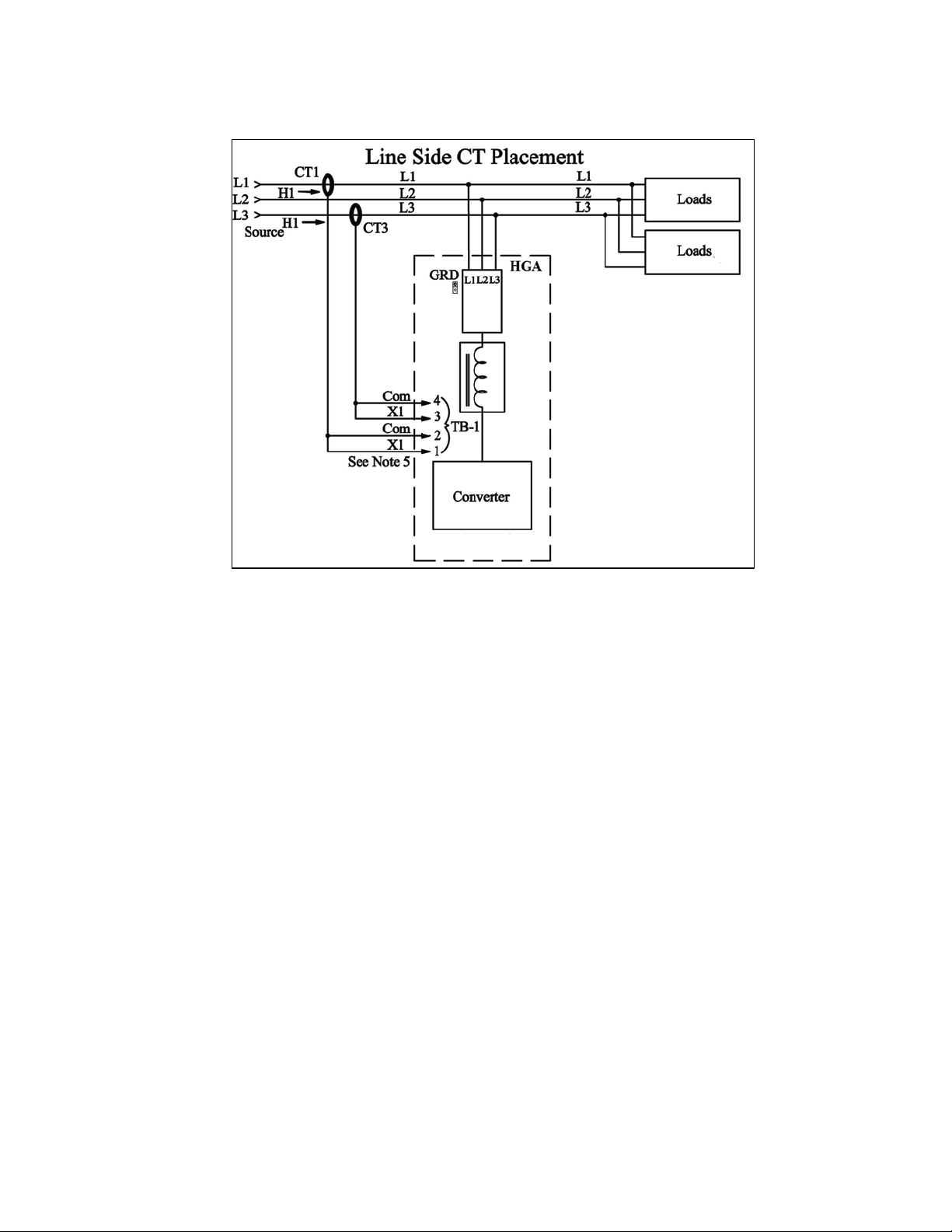
It is necessary for the HGA to moni tor the cur rent in P ha se “ A” ( L1) a nd P hase “C” ( L3). Stand-alone
HGA filters are designed for Line Side current transformer (CT) placement as shown in Figure 4.4a. It
is important that both CTs are on the same side of the HGA. The CTs sho uld be cente red around the
conductor. Optional Load Side CT placement is available for sin gle units as shown in Figure 4.4a.
The polarity of the CT is important; the “H1” marking on the CT must face the source. The secondary
windings o f the CT around conductor L1 should connect to TB-1 terminals 1 & 2 and the CT around
conductor L3 should connect to TB-1 terminals 3 & 4. The secondary wire of the CT identified as
“X1” must connect to the “X1” terminal of TB-1 for both CTs. Failure to maintain the correct polarity
and phasing wi l l cause an over-current fa ult . If this shoul d happen refer to the troubleshoo ting section.
The exact CT placement is dependent on the HGA’s configuration and size. Please refer to Figures
4.4a through 4.4i for the installation that applies.
Note: Units with black “TB-1” terminal blocks are shipped with two position shorting jumpers
installed between positions 1 & 2 and 3 & 4. This is done for your safety and to prevent equipment
damage. The jumpers are installed in the center of the block and can be identi fied by the gray to p.
After the load CTs are installed and wired, these jumpers must be removed for correct unit operation.
They can be removed with a standard flat blade screw driver (See Figure 5.3).
Note: CT operation can be verified via the HMI touchscreen feedback waveform plot screens.
Reference the HMI VLine & ILine Waveform Plot Sub Screen in Section 6 for details.
Table 4.2 – CT Range by Model Size
Amps CT Min Ratio
CT Max
Ratio
Notes
Factory technician start up required to
use CTs outside of the published range
32
Page 33

Current Transformer Diagrams
The following pages contain de ta ile d diagrams on the placement of CTs in relation to the HGA.
Figure 4.4a Line Side or Load Side CT Placement for stand-alone HGA filters rated at 45 to 100
amps, 480V.
Figure 4.4b Line Side or Load Side CT Placement for stand-alone HGA filters rated at 39 to 78 amps,
600V.
Figure 4.4c Line Side or Load Side CT Placement for stand-alone HGA filters rated at 200 amps,
Open or Type 1, 480V.
Figure 4.4d Line Side CT Placement for stand-alone HGA filters rated at 200 amps, Type 3R, 480V.
Figure 4.4e Line Side CT Placement for stand-alone HGA filters rated at 300 amps 480V.
Figure 4.4f Master and M ultiple Slave Para llel Units CT Plac ement for HGA filters rated at 45 to 100
amps, 480V.
Figure 4.4g Master and Multiple Slave Parallel Un its CT Placement for HGA filters rated at 3 9 to 78
amps, 600V.
Figure 4.4h optional Multiple Slave Parallel Units CT P lacement for HGA filter s rated at 39 to 100
amps.
Figure 4.4i Master and Multiple Slave Parallel Units CT Placement for HGA filters rated at 200 amps.
The pages after the CT Placement diagrams contain detailed diagrams on the current ratios and
dimensions of TCI Current Transformers. Contact TCI for CTs not found in figures 4.5, 4.6, or 4.7.
Figure 4.5 is the diagr am for Round Current Transformers.
Figure 4.6 is the diagram for Rectangular Current Transformers.
Figure 4.7 is the diagram for Solid Core Current Transformers.
33
Page 34

Figure 4.4a – Line Side or Load Side CT Placement – 45, 50, 90 and 100 am p, 480 volt
34
Page 35

Figure 4.4b – Line Side or Load Side CT Pl aceme nt – 39 and 78 amp, 600 volt
35
Page 36

Figure 4.4c – Line Side or Load Side CT Place ment – 200 amp, Open or Type 1, 480 volt
36
Page 37

Figure 4.4d – Line Side CT Placement – 200 amp, Type 3R, 480 volt
37
Page 38

Figure 4.4e – Line Side CT Placement – 300 amp, 480 volt
38
Page 39

Figure 4.4f – Master and Multiple Parallel Units CT Placement – 45, 50, 90 and 100 amp, 480 volt
39
Page 40

Figure 4.4g – Master and Multiple Slave Parallel Units CT Placement – 39 and 78 amp, 600 volt
40
Page 41

Figure 4.4h – Optional Multipl e Sla ve Parallel Units CT Placement – 39, 45, 78, 90 and 100 amp, 480 volt
41
Page 42

Figure 4.4i – Master/Slave CT Placement – 200 amp, 480 volt
42
Page 43

43
Page 44

Figure 4.5 – Current Transformer Diagram – Round
Figure 4.6 – Current Transformer Diagram – Rectangular
44
Page 45

Figure 4.7 – Current Transformer Diagram – Solid Core
45
Page 46

is not receiving power from an
!
Grounding
The HarmonicGuard Active filter p anel equip ment-grounding lug must be connected to the ground of
the premises wiring system. The equipment grounding connection must conform to the requirements of
the National Electric Code (NEC) and/or any other codes that ap ply to the installation site . T he gro und
connection must be made using a wire conductor. Metallic conduit is not a suitable grounding
conductor . The integrity of all ground connec tions should be periodically checked.
HarmonicGuard Active Filter Operation
Adjustments
• The HGA has been factory calibrated and thoroughly tested. There is no need to make
any adjustments.
Start Up (Commissioning)
Caution
Warning
Thoroughly check the i nstallation before applying power and operating the equipment for the
first time.
Before Applying Power for the First Time
Inspect the installation to make sure that all equipment has been completely and correctly
installed on accordance with the Installation Guidelines section of this manual.
• If it is a floor mount unit, check to see that it is securely anchored to the floor.
• Check the panel and the inside of the enclosure for any foreign objects, dirt, metal filings,
wire whiskers, and loose hardware.
• Verify that any covers or guards that were removed during installation were reinstalled.
• Ensure that the unit is properly grounded.
• Check for properly tightened co nnections.
General Operation
Please reference the Quick Start Guide in Section 1 for the first time power up procedure.
Since the HGA is an active filter, it is always operating whenever the power is applied.
Warning
Only qualified electricians should carry out all electrical installation and maintenance work on the
HarmonicGuard Active filter.
Disconnect all sources of power to the drive and HGA before working on the equipment . Do not
attempt any work on a powered unit.
Warning
Be aware everything ahead of the circuit breaker will still be energized. It is important to note
that the lack of lit LEDs does not necessarily mean that the HGA
external source.
46
Page 47

Warning
Only qualified electricians should carry out all electrical installation and maintenance work on the
■ Section 5
Maintenance and Service
HGA Reliability and Service L ife
The HGA has been designed and thoroughly tested at the facto ry to ensure tha t it will per form reliabl y
from the time it is put into service. The following periodic maintenance is recommended to ensure that
the HarmonicGuard Active filter will always perform reliably and provide the expected service life.
Periodic Maintenance
The following checks should be conducted monthly or more frequently when installed in harsh or
dusty environments.
• Check to see that the installation environment remains free from excessive vibration, exposure
to excessive dirt, moisture, and contaminants. Refer to the Pre-installation Planning section
of this manual.
• Check to make sure that the enclosure ventilation openings are clean and unobstructed.
• Clean the air filter in units that have filter ed air inlets. Clean as often as necessary to prevent
dirt build-up from impeding air flow.
• Check for any dust or dirt build-up on the fans and heat s ink fins.
• Check the o peration o f t he cooling fan.
• Inspect the interior of the enclosure for signs of overheated components. Clean the interior of
the enclosure whenever excess dirt has accumulated.
• Check the integrity of all power , ground, and control wiring connec t ions.
• All electrical connections must be re-torqued annually.
Many electronic components located within the filter are sensitive to static electricity. Voltages
imperceptible to human touch can reduce the life, and affect performance, or destroy sensitive
electronic devices. Use proper electrostatic discharge (ESD) procedures when se rvicing the filter
and its circuit boards.
Warning
HGA.
Disconnect all sources of power to the drive and HGA before working on the e quipment. Do not
attempt any work on a powered HGA.
This HGA unit contains high voltages and c a pacitors. Wait at least five minutes after
disconnecting power from the filter before you attempt to service the conditioner. Check for zero
voltage between all terminals on the capacitors. Also, check for zero voltage between all phases
of the input and output lines. All maintenance and troubleshooting must be done by a qualified
electrician. Failure to follow standard safety procedures may result in death or serious injury.
Unless an external disconnect means has been provided everything ahead of the filter circuit
breaker will still be energized.
47
Page 48

Reference Drawings
Typical HGA configurations are illustrated in Figures 5.1a, 5.1b, and 5.1c. There could be slight
differences between your unit and the configurations shown below. It is recommended that you refer to the
drawings provided with your specific equipment when conducting troubleshooting operations.
Figure 5.1a – General Schematic Bus Applied 39, 45, 78, 90 and 100 amp
*This drawing is for general reference only. Use the drawings supplied with the unit for installat ion.
48
Page 49

Figure 5.1b – General Schematic Bus Applied 200 Amp, Open and Type 1, Master/Master
*This drawing is for gene ral reference only. Us e the drawings supplied with the unit for inst allation.
49
Page 50

Figure 5.1c – General Schematic Bus Applied 200 Amp, Type 3R, Parallel
*This drawing is for general reference only. Use the drawings supplied with the unit for installatio n.
50
Page 51
!
Overload / Over Current Protected
The filter has factory set built-in electronic overload and over current protection. If the converter
current exceeds the preset instantaneous peak, the converter will shut do wn to prevent p ermanent
damage to the converter, and at which time it will indicate a fault. Faults that do not automaticall y
reset can be cleared by pressing the stop button on the HMI display.
An indicati on that the filter is going into overload will be observed by a gradual worsening of the
total harmonic distortion (THD), o r power factor, as the load increases. The HGA filter units can
be paralleled to increase total corrective current capability if a unit is undersized for a particular
application. Call TCI sales support for options to expand the installe d system current capabilit y.
Circuit Breaker Protection
Each converter section is protected by a thermo magnetic circuit breaker; in the event the HGA
experiences a catastrophic failure, or a destructive over current condition should occur. It also
provides a convenient disconnect means to isolate the converter from the power source. The size
and type of circuit breaker must not be altered without consulting TCI engineering since the circuit
breaker is an integral part of the UL file.
Notes:
• Open chassis units can be provided without circuit breakers. The end user must protect the
HGA with the following UL listed thermal magnetic common trip molded case circuit
breaker.
Warning
• 39, 45, 78 & 50 Amp: A max peak let-through current of 26 kA in correspondence with a
short circuit of 100 kA at 480 volt, and a trip current of 100 amps.
• 90 to 100 Amp: A max peak let-through current of 26 kA in correspondence with a short
circuit of 100 kA at 480 volt, and a trip current of 125 amps .
• 200 Amp: A max peak let-t hro ugh c urr ent o f 35 kA in correspondence with a short circuit
of 100 kA at 480 volt, and a trip current of 225 amps.
If the system breaker has been tripped, do not attempt to re-energize the HGA unit. Until the
cause of the trip has been determined.
Pre-Charge Circuit Over Current Protec tion
SCR’s are used to limit the converter power up in-rush current to a safe level once the converter
DC voltage has reached the threshold, SCRS will be turne d on and the charging resisto r will
be cut off from the unit. If fo r so me reas on thi s circ uitr y shoul d mal func tion, c lass CC f uses ar e
in the circuit to limit the max current as not to exceed the ratin gs of the components. Note: on the
50 to 100 amp units the fuses are located on the chassis; on the 175 and 225 amp unit s the fuses
are located on the interface/mother printed circuit board.
Over Temperature Protection
The converter has a thermal fold back mechanism that will automatically reduce unit output
current as the converter temperature approaches its shutdown threshold. Additionally, the
converter ha s an i nt er nal he a t sin k o ver temperatur e p r ot ec tio n whic h will sh ut d o wn t he c o nver te r
if the threshold is exceeded. The fans will continue to run and o nce the hea t sink co ols do wn the
converter will automatically restart.
There are secondary over temperature circuits which monitor the temperature of the power
resistors and inductors locate d on the chassis of the HGA. The sensors are snap action switches
activated when the threshold is reached. This over temp would be an indication that cooling fans
51
Page 52

have failed or something more serious with the operation of the converter. For this reason this
fault will latch and will remain latched until po wer is cycled. The indicator light located on relay
CR-2 will not be lit with this type of over temp fault.
Troubleshooting
Current Transformer Orientation Troubleshoo ting
Failure to maintain the correct p olarity and phasing of the current trans formers (CTs) will cause an
over current fault on power up. The converter will never attempt to run; it will stay in a stopped
condition. Possibly the CTs are installed backwards or the secondary wiring is incorrect, if this is
suspected refer to the steps below to isolate the error.
Note: CT operation can be verified via the HMI touchscreen feedback waveform plot screens.
Reference the HMI VLine & ILine Waveform Plot Sub Screen in Section 6 for details.
Warning
Only qualified electricians should carry out all electrical installation and maintenance work on the
HGA. Failure to follow standard safety procedures may result in death or serious injury.
Disconnect all sources of power to the drive and HGA befo re working on the equipment. Do not
attempt any work on a powered HGA. Also, check for zero voltage between all phases of the input and
output lines .
Operating current transformers with the secondary winding open can r esult in a high voltage
across the secondary terminals which may be dangerous to personnel or equipment.
1.) If the CTs and wiring is easily accessible double check the CT orientation for proper direction, and
trace the secondary wiring against Figure 4.3 for polarity, phasing and connection to terminal TB-
1. Correct any errors and apply power for proper power-up, if it doesn’t clear the fault or if
accessibility is too difficult pro c e e d to step #2.
2.) There is a possibility that the CTs markings are different from Figure 4.3. This could a ffect the
polarity, to verify this try reversing the two leads on TB-1 positions 1 &2, do the same with wires
in positions 3 & 4. Apply power for proper power-up; if it doesn’t proceed to #3.
3.) Reverse just one set of CT leads at a time, first # 1 & 2; verify power-up. If it doesn’t work put
wires 1 & 2 back and now try the same with wires 3 & 4. Apply power for proper power-up; if it
doesn’t replace all wiring to its original positions, and proceed to #4.
4.) There is a possibility that the phasi ng of the CT L1 and L3 are incorrect. To test this theory swap
the two wires o n TB-1 positions 1 & 2 with the two wires in positions 3 & 4. Apply power for
proper power-up; if it doesn’t repeat steps 2 and 3.
5.) If the HGA doesn’t indicate a run status after completion of steps 1 through 4 contact TCI
technical support for further assistance.
Warning
System Failure
The Digital Signal Processor is continually mo nitoring the perfor mance and fault statu s of the filter. It
will shut do wn the converte r section if the p rocessor should sense a fault. The filter is also equipped
with a circuit breaker providing a second layer of over current protecting for the converter section. The
circuit breaker can also serve as a means of electrical isolation from the system power grid. It is
recommended by TCI that all power to the HarmonicGuard Ac tive filter be disconnected. If you elect
to service the HGA by using the circuit breaker to isolate the converter section, please take special note
of the following warnings:
Many electronic components located within the filter are sensitive to static electricity. Voltages
imperceptible to human touch can reduce the life, and affect performance, or destroy sensitive
electronic devices. Use proper electrostatic discharge (ESD) procedures when se rvicing the filter and its
circuit boards.
52
Page 53
Warning
Only qualified electricians should carry out all electrical installation and maintenance work on the
HGA.
Disconnect all sources of power to the drive and HGA before working on the e quipment. Do not
attempt any work on a powered HGA.
This HGA unit contains high voltages and c a pacitors. Wait at least five minutes after disconnecting
power from the filter before you attempt to service the conditioner. Check for zero voltage between all
terminals on the capacitors. Also, check for zero voltage between all phases of the input and output
lines. All maintenance and troubleshooting must be done by a qualified ele c trician. Failure to follow
standard safety procedures may result in death or serious injury. Unless an external disconnect means
has been provided everything ahead of the filter circuit breaker, including the reactors, will still
be energized.
Required Equipment
• AC voltmeter and ammeter or multimeter designed for true RMS measurements in a
harmonic rich circuit and suitab le for the r a te d current and voltage marked on the
nameplate. The meter should have 1000 volt minimum isolation.
• Clamp-on current probe suitable for the rated current and voltage marked on the
nameplate.
• Clip-on voltage probes suitable for the rated voltage marked on the nameplate Select
probes that can be securely clipped on to the test points without shorting between
points or falling off.
Note: when disconnecting wires from components and terminations, mark the wires to
correspond to their component and terminal connection. Extr eme Care should be ta ken when
removing the fast-on terminals from the circuit board. Excessive force will result in damaging
the interface board and require the converter to be repaired by TCI authorized personnel only.
53
Page 54

Converter Inspection
• Verify that power has been removed from converter, and 5 minutes has passed before
inspection.
• Remove plastic cover from over converter section.
• Visually check the circuit boards for debris; contamination; overheated traces; burnt
circuit board; overheated, cracked, or broken components; corrosion; and poor solder
joints.
• Check all wires and terminals connected to the circuit boards.
• Check the four electrolytic cap acitors for bulges, ruptures, pop ped vent plugs,
discoloration, or leakage.
• Check the p ower semiconductors mounted to heat-sink for cracked cases, ruptures,
debris, arcing, and burning.
• Check for any loose connections if no apparent damage is found to the power
semiconductors.
• Measure resistance of power semiconductors using a multimeter set on the diode check
setting, see Figure 5.2. Look for opens, ∞,
your meter connected to the far right negative terminal of the capacitor bank, measure
with the black lead of the meter to each of the three output terminals (bus bars), the
reading should be approximately 0.35Ω. Reverse the meter leads and repeat measuring to
each terminal. This time a low reading will be present which will continue to increase;
this is an indication of a capacitor charging. Next connect the black meter lead to the
“positive capacitor terminal” and again measure to each of the output terminals with the
other lead; the reading should be approximately 0.35Ω
repeat measuring to each terminal. Again it will be a low reading which will continue to
increase. If the readings are as described, in all likelihood the power semiconductors are
good. If any readings are opens or dead shorts it will be an indication that something is
bad in the power section. Do not reapply power if you are not sure the IGBT’s are good.
or dead short readings. With the red lead of
. Reverse the meter leads and
Figure 5.2 – 39, 45, 78, 90, 100, and 200 Amp Power Component Layout
54
Page 55

Warning
Figure 5.3 – TB-1 Terminal Block
Only qualified personnel should operate the HarmonicGuard Active filter with the door open. Failure
to follow standard safety procedures may result in death or serious injury. Do not attempt any work
on a powered filter converter.
The HGA contains high voltages and capacitors. Wait a t le ast five min utes after disconnecting po wer
from the converter before you attempt servicing. Check for zero voltage between all terminals to the
converter. Be aware everything ahead of the circuit breaker will still be energized.
55
Page 56

Figure 5.4 – Troubleshooting Flow Chart
56
Page 57

Replacement Parts
If replacement parts are needed, please contact your TCI representative. To ensure that the
HarmonicGuard Active filter continues to perform to its original specifica tions, replacement parts
should conform to TCI specifications. Use of non-TCI approved components will void all
warranties.
Factory Contacts and Techni cal S upport
For technical suppor t, contact your local T CI distributor or sales representative. You can contact
TCI directly at 1-800-824-8282. Select "Customer Service" or "Technical Support" and have your
HarmonicGuard Active filter nameplate information available and any drawings.
Outline and Mounting Dimension Drawings
Outline and mounting dimension drawings show the overall enclosure dimensions, the conduit access areas
and the wiring connection points. The major internal components are shown pictorially.
57
Page 58

Figure 5.5 – 39 and 78 amp Open Chassis Filter, Open Transformer
58
Page 59

Figure 5.6
59
– 39 and 78 amp Open Chassis Filter, Type 3R Transformer
Page 60

Figure 5.7
60
– 39 and 78 amp Type 1 Filter, Type 3R Transformer
Page 61

61
Figure 5.8 – 45, 50, 90 and 100 amp Open Chassis
Page 62

62
Figure 5.9 – 45, 50, 90 and 100 amp Type 1 Enclosed
Page 63

63
Figure 5.10 – 200 amp Open Chassis
Page 64

Figure 5.11 – 200 Amp Type 1 Enclosed
64
Page 65

Figure 5.12 – 200 Amp Type 3R Enclosed
65
Page 66

Figure 5.13 – 300 amp Type 1 Enclosed
66
Page 67

Figure 5.14 – 300 amp Type 3R Enclosed
67
Page 68

■ Section 6
HMI Introduction
The Interface Module provides the user with a convenient way to monitor the operation of TCI’s
HarmonicGuard Active filter and allows for the ability to adjust run-time set-points under password control.
This section describes how to insta ll, operate, and maintain the Interface Module.
Overview
The Interface Module has three major components; the Interface PCB, the HMI Display and an option
network Communications Gateway (see Figure 6.1).
The interface PCB contains a Chassis Communications Port that connects to the power converter of the
HarmonicGuard Active filter. The interface PCB translates status and commands data between the power
converter controls and the HMI Display. The interface PCB also contains the 24V Relay I/O for basic status
monitoring and run/stop control of the HarmonicGuard Active filter.
The HMI Display is a 6” color Touchscreen display containing a series of status screens that provide the user
with a convenient way to monitor the operation of the HarmonicGuard Active filter. The HMI display also
contains an integrated ModbusRTU network connection for remote monitoring of the HarmonicGuard Active
filter.
The optional network Communications Gateway can be connected to the integrated ModbusRTU network
connection in the HMI Di s play to translate the ModbusRTU protocol to an alternate Field bus or Industrial
Ethernet protocol such as Ethernet/I P.
Figure 6.1 – Interface Module Components
68
Page 69

Caution
review the more specific information provided by the drawings shipped with the module. Information
!
Additiona l Infor mation
This section provides general information describing the Interface Module. Be sure to carefully
from by the drawings takes precedence over the information provided in this section.
The information and rat ings given in this manual are approximate and should not be used for any
purpose requiring exact data. Contact the factory in situations where certified data is required. All
data is subject to change without notice.
Receiving Inspection
The Interface Module has been thoroughly inspected and functionally tested at the factory and carefully
packaged for shipment. After receiving the unit, immediately inspect the shipping container and report any
damage to the carrier that delivered the unit. Verify that the part number of the unit received is the same as
the part number listed on the purchase order. See appendix for part numbering details.
69
Page 70

o Make sure the installation location will not be exposed to direct sunli ght, excessive
o Select a mounting area that will allow adequate cooling air.
o Make sure that all wiring conforms to the requirements of the National Electric Code
o Ground the HM I display by using the grounding terminal. Not only does this act as a
o Check all connections and components thoroughly before applying power to the
o Check the panel and the inside of the enclosure for any foreign objects, dirt
!
Installa tion Guidelines
Checklist
The following are the key points to be followed for a successful installation. These points are explained in
detail in the following sections.
vibration, corrosive or combus tible airborne contaminants, excessive d ir t or liquids.
(NEC) and/or other applicable electrical codes.
safety, but it also filters out electrical noise.
equipment.
and/or loose hardware.
Location
Environment
The location of the Interface Module should be a suitable environment to assure proper performance and a
normal operating life. Refer to the environmental speci fi cations furnished i n this manual, and noted on the
drawings with the Interface Module.
Warning
Unless specifically labeled as approved for such use, this equipment is not suitable for use in an
explosive atmosphere or in a "Hazardous (Classified) Location" as defined in article 500 of the National
Electrical Code (NEC).
• Display front rated Type 1 & 4X
• Avoid direct sunlight
• Avoid corrosive liquids or gasses
• Avoid explosive or combustible gases or dust
• Avoid excessive airborne dirt and dust (Pollution Degree 2, according to EN50178 and UL508C)
• Avoid excessive vibration (0.152 mm (0.006 in.) displacement, 1G peak)
Mounting
Mounting requires at least a depth of 4” (102 mm). The Interface Module will mount in a panel with a
thickness of 0.02 to 0.35 inch (0.5-9.0 mm) with an opening 6.79” by 5.21” (173 by 133 mm). Fit the
Interface Module assembly into the opening carefully pressing on all four corners. Use the mounting
hardware (4 sets) to secure the assembly on the corners.
Warning: to avoid damaging the case, do not exceed a tightening torque of 3.47 to 4.34 lbs-in (0.39-0.49
Nm). Care s hould be taken not to mount the Interface Module too close to a heat source (such as power
resistors) which could be located behind the Interface Module.
70
Page 71

Caution
The display panel is waterproof. But care should be taken to prevent grease, corrosive liquids and sharp
!
objects from contacting the front panel.
Warning
Many electronic components located within the Interface Module and HMI are sensitive to static
electricity. Voltages imperceptible to human touch can reduce the life, and affect performance, or
completely destroy sensitive electronic devices. Use proper electrostatic discharge (ESD) procedures
when servicing the Interface Module and HMI.
Wiring
Note: Some of the following sectio ns only apply if the Interface Module is not factory installed.
A wiring block diagram of the Interface Module components is available in Figure 6.2.
When selecting a mounting loca tion for the unit, plan for the routing of commutation and power cable. Kee p
the wiring away from power wire s where electrical noise could be ind uced. All wiring should conform to the
requirements of the National Electric Code (NEC) and/or other applicable electrical codes. The length of the
communication cable between the Interface module chassis communication port and the HarmonicGuard
Active filter power converter module should not exceed 25 feet (7.6 meters).
Figure 6.2 – Interface Module Connections
71
Page 72

Terminal
Pin
Description
Label
Rating
J1 1 HMI Display
For factory use
N/A
1
Not Connected
2 B 3
Ground
4
A
5
Not connected
1
Neutral
2
Line
J4
1
Micro Programming
For factory use
N/A
1
24 VDC
2
Common
3
Not Connected
1
24 VDC
2
Start
Interface PCB Connections
Most customer connections to the Interface module will be made on the Interface PCB. Refer to connection
diagrams in Figure 6.3. The details of the power and communications terminals are shown in Table 6.1, form
C relays are available on the Interface PCB. These connections are shown in Table 6.2. Four outputs a re
available on the Interface PCB.
The relay start command input connection on J22 of the interface PCB allows a contact closure to send a r un
command to the HarmonicGuard Active filter. The relay start command input will only be acknowledge if the
Relay Run/Stop Enable is set to Enabled on the HMI Display setup screen. See Figure 7.14 for details.
Pressing stop locally via the HMI D isp lay will set the enable for the rela y start command to DISABLED.
Figure 6.3 – Interface PCB connections
Table 6.1 – Power & Communications Terminals
J2
J3
RS485
Input Power
N/A
120 VAC
J19
J22
Note: The power terminal on the back of the HMI display accepts 28 to 14 AWG stranded wire, with a
tightening torque of 4.4 in-lb (0.5 Nm).
72
HMI Power Supply
Start Command
24 VDC
Contact Closure
Page 73

Tightening
Torque
Wire
Range
1
Normally Closed
2
Common
3
Normally Open
1
Normally Closed
2
Common
3
Normally Open
1
Normally Closed
2
Common
3
Normally Open
1
Normally Closed
2
Common
3
Normally Open
Table 6.2 – Form C Relay Contacts
Terminal Pin Description Label
J5
J6
J7
J12
Note: Form-C relay contacts are gold plated with a load rating of 0.6A @ 125VAC general use; 0.2A @
250VAC, 0.6A @ 125VAC, 2A @ 30VDC resistive. The minimum permissible load rating is 10uA, 10mVDC.
Run
Power On
Fault
Current
Limit
4.4 lbs-in (0.5 Nm) 28-14 Awg
4.4 lbs-in (0.5 Nm) 28-14 Awg
4.4 lbs-in (0.5 Nm) 28-14 Awg
4.4 lbs-in (0.5 Nm) 28-14 Awg
HMI Display Connections
Note: The following section describes the d e fault ModbusRTU network connection available on the base
model. If an optional advanced network Communications Gateway is included in the Interface Module see
the appendix for the specific Communications Gateway configuration.
The HMI display implements a ModbusRTU slave device over RS-485. This network connection is available
on the COM2/3 DB9 connector on the back of the HMI Display (see Figure 6.4).
The output r egisters fro m the HarmonicGuard Active filter are mapped to Modbus register address 40500.
The input re gisters to the Har monicGuard Active filter are mapped to Modbus register address 40564. For
definitions of the input and output data available via the network connection see the Network Interface
section below.
If the optional network Communications Gateway is present the integrated ModbusRTU interface on the HMI
Display will not be available. When configured, the Communications Gateway will occupy t he ModbusR TU
COM2/3 DB9 connector on the back of the HMI Display.
73
Page 74

COM2/3
DB9 Pin
1
no connect
-
2
no connect
-
3
no connect
-
4
D+
RS-485 B (non-inverting)
5
GND
RS-485 SC/G
6
no connect
-
7
no connect
-
8
no connect
-
9
D-
RS-485 A (inverting)
Parameter
Default Value
Units
Baud Rate
19200
bps
Data Bits 8 bits
Stop Bits 1 bits
Parity
Even
-
Slave ID
113
-
ModbusRTU
Connection
Figure 6.4 – HMI ModbusRTU Connection
Table 6.4 – Modbus Connector Pin Definitions
Signal Name Signal Type
Table 6.5 – ModbusRTU Protocol Settings
Communications Gateway Connections ( Optional)
If an optional advanced network Communications Gateway is included in the Interface Module see the
appendix for the specific Communications Gateway wiring details.
If the optional network Communications Gateway is present, the integra te d ModbusRTU interface on the
HMI Display will not be available. When configured, the Communications Gateway will occupy the
ModbusRTU COM2/3 DB9 connector on the back of the HMI Display.
74
Page 75

HMI Graphic Element
Example
Description
Buttons will appear raised or
and command conditions.
Indicator status fields will appear
Display fields will appear flat.
Numerical Entry fields appear
The Navigation Bar allows for easy
The Title Bar contains the current
■ Section 7
Operation
HMI Screen Elements
This section focuses on the operation of the HMI Display. The HMI Display contains several screens that
allow the user to monitor the status of the line/load and the HarmonicGuard Active filter. Additionally the
HMI display can be used for local run/stop control and basic setup of the HarmonicGuard Active filter.
Table 7.1 – General HMI Screen Elements
Buttons
Indicators
Numerical Displays
Numerical Entry Fields
Navigation Bar
Title Bar
depressed, depending on set point
flat and are read only.
Numerical displays are read only.
indented. Selecting them will open
a keypad for numerical entry.
navigation between the five major
HMI screens. The Navigation Bar
appears on all HMI screens.
system time, screen selection, and
a stop button to turn off the system.
The Navigation Bar appears on all
HMI screens.
75
Page 76

Indicator
Navigation
HMI Display
Power LED
Title Bar
Button
Numerical
Display
Figure 7.1 – HMI Display
Bar
Initialization
When first powered, the green LED (Power) on the HMI Display will light (see Figure 7.1).
After a five second boot up sequence the Home Screen will be displayed. If the home screen is not displayed
and power is available to the HMI Display see the troubleshooting section at the end of this user manual for
diagnosing common problems.
HMI Screens
Home screen
The Home screen displays a dashboard of overall filter status information and allows the user to run and stop
the HarmonicGuard Active filter. Figure 7.2 illustrates the func ti o ns.
Figure 7.2 – Home Screen
76
Page 77

Screen Element
Description
Indicates if a converter fault is active and preventing the
This gauge displays the current filter capacity as a percentage
Run/Stop Button
Runs and stops the HarmonicGuard Active filter.
When the HarmonicGuard Active filter is in a stop mode the
Displays current line/load power factor. 1.00 indicates unity
Line Frequency
Displays the supply voltage coming into the HarmonicGuard
Displays the current line/load phase current in Amps RMS.
Filter Status Display
% Filter Current Used
Display
System State
Indicator (located
immediately below
stop button)
Table 7.2 – Home Screen Elem ent s
HarmonicGuard Active filter from running. If a fault occurs the
indicator will flash red and display “Fault”. Specific Fault codes
can be viewed on the “Fault” Screen.
of total available capacity. In normal operation the display will
read “Nominal”. If the unit output corrective current is above
95% of maximum capacity the indicator light will turn red and
display “At Capacity”. When the converter is at capacity the
Relay K4 (J12 Connector), and J11 Contacts used for a remote
indicator will also be energized. If the monitor continually
displays “At Capacity” a second filter may be required to handle
the load. Please contact TCI for assistance.
“Status” light will turn red and display “Stopped”. When the
converter is running the status light will be green and will
display “Running”. The status light will also show if the
HarmonicGuard Active filter is in Input line Sync mode, Reset
mode, Precharge mode, Calibrate mode, Power Save mode or
Faulted. When the HarmonicGuard Active filter is fault ed it wil l
shut down automatically
Power Factor Display
Display
Supply Voltage
Line/Load Current
Display
power factor. A negative power factor indicates lagging power
factor.
Displays the current utility line frequency in Hz.
Active filter.
NOTE: the displayed current is affected by the CT Ratio
configuration on the “Setup” page.
77
Page 78

Screen Element
Description
Use this button to get to the “Line/Load Status”
Displays the current utility phase to phase line
Displays the current line/load phase current in
Displays current line/load power factor. A value of
Frequency Display
Displays the current utility line frequency in Hz.
Run/Stop Button
Runs and stops the HarmonicGuard Active filter.
This button will take the user to the “Converter
Phase to Neutral voltage,
The “Waveform” screen buttons will take the user
When the user presses the “Trend” button the
“Historical Trend screen menu is displayed
Status Screen
The Status screen shows more specific information on the performance of the system such as current and
voltage waveforms, Power Factor and information specific to the Line/Load screen and Converter screen.
Figure 7.3 explains the main “Status” Screen.
Figure 7.3 – Status Screen
Table 7.3 – Status Screen Elements
Line/Load Button
Volts Display
Current Display
Power Factor Display
Converter Button
Line Voltage, Line/Load
Current, and Converter
Current, and Vline/Iline
Waveform Screens
Sub Screen (see Figure 7.6).
voltage in Volts RMS.
Amps RMS.
1.00 indicates unity power factor. A negative power
factor indicates lagging power factor.
Status” Sub Screen (see Figure 7.4).
to one of the four real-time waveform capture
screens: Phase to Neutral voltage, Line Voltage,
Line Current, Converter current, or VLine/ILine plot
(see Figures 7.7 and 7.8).
Trend Menu Screen
78
(see Figure 7.9).
Page 79

Screen Element
Description
Run/Stop Button
Runs and stops the HarmonicGuard Active filter.
Displays the present HarmonicGuard Active filter
Displays the internal DC Link Bus voltage of the
Displays the present HarmonicGuard Active filter
This gauge displays the current filter capacity as a
Displays the current state of all enables that affect the
Back Button
Returns to the main status screen.
Converter Status Sub Screen
The converter status sub screen shows the present status of the HarmonicGuard Active filter power converter
module.
Figure 7.4 – Converter Status Sub Screen
Table 7.4 – Converter Status Sub Screen Elements
Current Display
Link Voltage Display
Heatsink Temp
Display
% Filter Current Used
Display
Run Enable Summary
output corrective current in Amps RMS.
HarmonicGuard Active filter in Volts DC.
power converter heat sink temperature in Degrees
Celsius.
percentage of total available capacity. In normal
operation the display will read “Nominal”. If the unit
output corrective current is above 95% of maximum
capacity the indicator light will turn red and display “At
Capacity”. When the converter is at capacity the
Relay K4 (J12 Connector), and J11 Contacts used for
a remote indicator will also be energized. If the
monitor continually displays “At Capacity” a second
filter may be required to handle the load. Please
contact TCI for assistance.
running of the HarmonicGuard Active filter. If a button
is red that option is disabled and if it is green that
option is enabled. If the “Auto Start” is enabled a
countdown timer will run to the right of the button,
when the count reaches 0 the converter will start (See
Figure 7.5).
79
Page 80

Screen Element
Description
Run/Stop Button
Runs and stops the HarmonicGuard Active filter.
Shows if the start or stop button is enabled.
Changes to blue if enabled or the left button is pressed,
will start.
Changes to blue if enabled or the left button is pressed, if
green and read “RUN”.
Changes to blue if enabled or the left button is pressed, if
This button will take you back to the converter status
Run Enable Summary Sub Screen
The Run Enable Summary sub screen shows state of all the enables that affect the running of the
HarmonicGuard Active filter.
Figure 7.5 – Run Enable Summary Sub Screen
Table 7.5 – Run Enable Summary Sub Screen Elements
Auto Start
Remote Relay
Remote Network
Back
and the countdown timer (to the right of the button) will
start. When it reaches 0 the HarmonicGuard Active filter
enabled the HarmonicGuard Active filter can be
remotely stopped with a contact closure. When enabled
and the option is active the field to the right will be
enabled the HarmonicGuard Active filter can be remotely
stopped/started with a contact closure. When the contact
is closed the unit will run and when opened the uni t will
stop. When enabled and the option is active the field to
the right will be green and read “RUN”.
screen.
80
Page 81

Volts Display
Displays the current utility phase to phase line voltage in Volts
RMS.
Displays the current line/load phase current in Amps RMS.
Power Display
The three phase real power (P) of the line/load in kW.
Apparent Power
The three phase apparent power (S) of the line/load in kVA.
Power Factor
Displays current line/load power factor. 1.00 indicates unity power
Displays the Total Harmonic Distortion of the utility Line/Load
current as a percentage.
Displays the Total Harmonic Distortion of the utility line Voltage as
a percentage.
Displays the reference Total Harmonic Distortion of the utility
Run/Stop Button
Runs and stops the HarmonicGuard Active filter.
Back Button
Returns to the main Status Screen
Line/Load Status Sub Screen
The Line/Load Status Sub Screen shows more specific information regarding the source and load voltage,
current, power, power factor and THD measurements.
Figure 7.6 – Line/Load Status Sub Screen
Table 7.6 – Line/Load Status Sub Screen Elements
Screen Element Description
Current Display
Display
I THD Display
V THD Display
I THD Ref Display
NOTE: the displayed current is affected by the CT Ratio
configuration on the “Setup” page.
factor. A negative power factor indicates lagging power factor.
Line/Load current in percent. This THD display is the uncorrected
THD of the Line/Load taken when the HarmonicGuard Active filter
was not running.
81
Page 82

Screen Element
Description
The “Refresh” button will reload the data from the HarmonicGuard
1X, 2X and 4X
Waveform zoom buttons will redraw the present data at a different
Waveform Plot Sub Screens
The HMI display supports capture and display of real time system voltage and current data. Three phase
waveform data can be viewed for Line Voltage, Line/Load Current, and Converter Corrective Current.
The waveform screens contain a zoom feature which supports three magnitude scales: 1 X, 2 X and 4X (see
Figure 7.7). The Refresh button on the waveform screens will update the plot with new data from the
HarmonicGuard Active filter converter.
Figure 7.7 – Example Waveform Plot Sub Screens (Converter Corrective Current)
Table 7.7 – Waveform Plot Sub Screen Elements
Refresh Button
Buttons
Active filter power converter controller and redraw the waveform
plot.
scale.
VLine & ILine Waveform Plot Sub Screen
The VLine & ILine Wavefor m Plot Sub Screen is a vailable to verify the proper installation of the
HarmonicGuard Active filter power connections and system current CT feedbacks. The waveform plot shows
voltage and current feedback for both Phase A and C o n the same pl ot. When the HarmonicGuard Active
filter is powered, but in the stopped state this plot can be used to check for the following:
• Proper Line Voltage phase rotation
• Proper Line/Load Current phase rotation
• Proper Line Voltage and Line/Load Current relative polarity and phase.
• Missing/Open Circuit System Current CT Feedback
In the event that the HarmonicGuard Active filter performance is degraded the VLine & ILine waveform plot
should be examined as a means to determine if any system connection errors are present. Prior to examining
the VLine & ILine waveform plot, the HarmonicGuard Active filter should be put in the stopped state by
pressing the stop button in the upper left corner of the HMI screen. Figure 7.8 shows the VLine & ILine
waveform plot sub screen for a properly connected, but non-running HarmonicGuard Active filter when
connected to a typical non-linear, rectifier load. Note the following characteristics:
• Phase C voltage (Blue) leads Phase A voltage (Green).
• Phase C current (Yellow) leads Phase A current (Red).
• Phase A voltage (Green) and Phase A current (Red) are in phase and the same polarity.
• Phase C voltage (Blue) and Phase C current (Yellow) are in phase and the same polarity
82
Page 83

Figure 7.8 – VLine & ILine Waveform Plot of a Properly Connected
VLine & ILine Waveform Plot Sub Screen with
Connection
Connection Error
Phase rotation is
To correct swap
HarmonicGuard Active filter (unit in stopped state)
Note: The example VLine & ILine Waveform Plot screens apply to rectif ie r loads only. For low power factor
loads the VLine & ILine wa veform screen will appear different.
Table 7.8 sho ws what the VLine & ILine Waveform Plot Sub Sc reen would look like with various
connection errors present in the system.
Rectifier Load
Table 7.8 – VLine & ILine Waveform Plot Screen Examples when
Typical Connections Errors Present in System
Error
Description
Incorrect:
Phase A leads
Phase C instead
of Phase C
leading Phase A.
Resolution
Phase A and Phase
C HarmonicGuard
Active filter power
connections AND
swap Phase A and
Phase C system CT
current feedback
then recheck plot.
83
Page 84

Phase C system
Check Phase C CT
Phase A and
To correct swap
Phase A current
To correct, re-install
CT current
feedback missing:
Phase C current
is zero while
Phase A current
is present.
Phase C CT
current feedback
swapped:
Phase A current
(red) in phase
with Phase C
voltage (blue)
instead of Phase
A voltage (green).
for open circuit or
loose connection.
Phase A and Phase
C system CT
current feedback
and recheck plot.
(red) is opposite
polarity of Phase
A voltage (green)
and Phase C
current (yellow) is
opposite polarity
of Phase C
voltage (blue).
both Phase A and
Phase C system
CTs with polarity
arrow in opposite
direction OR swap
positive and
negative
connections of
each CT at HGA
filter terminal block
then recheck plot.
84
Page 85
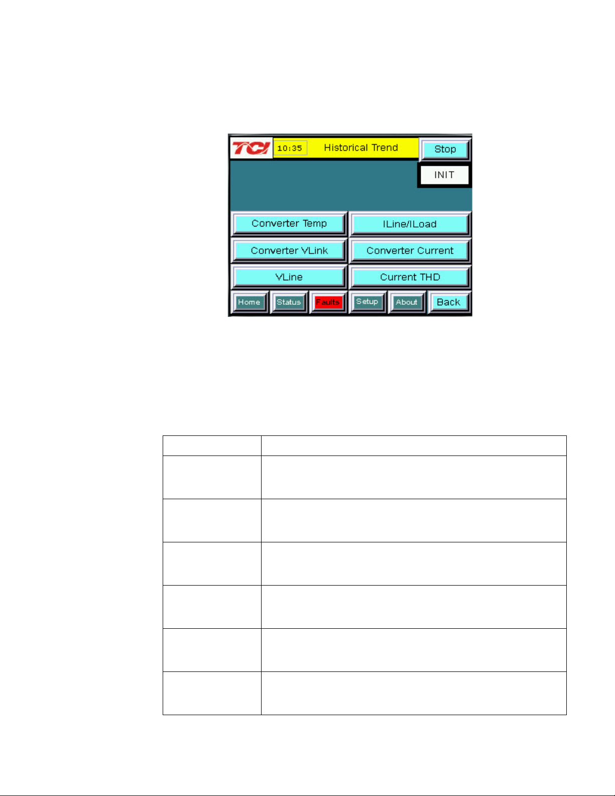
Screen Element
Description
Opens the HarmonicGuard Active filter heatsink temperature
Opens the HarmonicGuard Active filter DC Link Voltage historical
Opens the utility input RMS voltage historical trend graph screen.
Opens the line/load RMS current historical trend graph screen.
Opens the HarmonicGuard Active filter RMS current historical
Opens the line/load Total Harmonic Distortion historical trend
Historical Trend Plot Menu Sub S creen
From the historical trend plot menu sub scree n you can view trend gr aphs of various HarmonicGuard Active
filter system signals (see Figure 7.10).
Figure 7.9 – Historical Trend Plot Menu Sub Screen
Table 7.9 – Historical Trend Plot Menu Sub Screen Elements
Converter Temp
Button
Converter VLink
Button
VLine Button
ILine/ILoad Button
Converter Current
Button
historical trend graph screen. This signal is sampled every 15
seconds and historical data is maintained for 10 hours.
trend graph screen. This signal is sampled every 3 seconds and 2
hours of historical data is maintained.
This signal is sampled every 3 seconds and 2 hours of historical
data is maintained.
This signal is sampled every 3 seconds and historical data is
maintained for 2 hours.
trend graph screen. This signal is sampled every 3 seconds and 2
hours of historical data is maintained.
Current THD
Button
85
graph screen. This signal is sampled every 3 seconds and 2
hours of historical data is maintained.
Page 86

Screen Element
Description
Run/Stop Button
Runs and stops the H armonicGuard Active filter.
Plot Scale Display
Indicates the date and time the left-most sample displayed on the
Allows the user to scroll through all sample points available in the
Trend Plot Display
The historical graph of the value being sampled over time.
Historical Trend Plot Sub Screens
The historical trend plot screens gra ph time-stamped feedback data over an extended period of time. Once the
trend plot display data buffer is full the o ldest data is overwritten. Historical data can be viewed using the
integrated scroll bars of the tre nd plot. All trend plot data is maintained between power on/off cycles of the
HarmonicGuard Active filter. See Figure 7.10 for an example of a typical trend graph (trend plot example is
for the HarmonicGuard Active filter power converter heatsink temperature measurement). For data buffer
sample times and size see Figure 7.10.
(located on the left side
of the graph)
Right Timestamp
Left Timestamp
Scroll Bar
Figure 7.10 – Example Historical Trend Plot Sub Screen
Table 7.10 – Trend Plot Screen Elements
Indicates the magnitude of the samples of the trend plot. The scale
varies with each of the trend plots.
Indicates the date and time the right-most sample displayed on the
screen was taken.
screen was taken.
trend plot data buffer.
86
Page 87

Screen Element
Description
This button will remove all faults from the list if the fault conditions
fault history log.
When a fault occurs the fault screen will display information about
• Fault description
This button will take the user to the “Fault History” sub screen
where previous faults can be reviewed.
Fault Screen
This button takes the user to the “Active Fault” screen (see Figure 7.11) which lists all of the active faults.
The faults will stay in this list until the “ Rese t” , or “Stop” button is pressed or the fault self clears. From here
the user can also go to the “Fault History” screen.
Figure 7.11 – Fault Screen
Table 7.11 – Fault Screen Elements
Stop Button Turns off the HarmonicGuard Active filter.
Reset Button
Fault Trip Entry
Display
History Button
have cleared. Once cleared, a fault will still be viewable in the
the fault including the (from left to right across the screen):
• Fault bit mask number
• Fault timestamp
• Fault code (see Table 7.12)
87
Page 88

Fault
Critical or
Auto or Manual
Critical
Manual*
Desat (IGBT Gate Driver) Fault
Phase A
Critical
Manual*
Desat (IGBT Gate Driver) Fault
Phase B
Critical
Manual*
Desat (IGBT Gate Driver) Fault
Phase C
1000
Non-critical
Auto
DC Bus Overvoltage
1250
Non-critical
Auto
DC Bus Undervoltage
3000
Non-critical
Auto
Overcurrent on Phase A
3010
Non-critical
Auto
Overcurrent on Phase B
3020
Non-critical
Auto
Overcurrent on Phase C
4000
Critical
Power Cycle**
Overtemperature
4250
Non-critical
Auto
Undertemperature
7000
Non-critical
Auto
Calibration Fault
7010
Non-critical
Auto
Communications Fault
Non-critical
Auto
Fault location indication. Fault
unit in the system.
Table 7.12 – Fault Codes
Code
10
20
30
Unit N
Faulted
Non-critical Fault
Reset Fault Description
originated in Unit N where N is in
the range 1 to 8. For factory
configured parallel systems the
unit numbers are sequential
ordered from left to right when
looking at the front of the
system. Unit 1 is the left most
*Critical faults flagged with a manual r e set r e quire a HMI stop button or run/stop switch stop command at the
unit to clear.
**Critical faults flagged with a power cycle reset require a manual on/off power cycle of the unit to clear.
Fault History Sub Screen
The “Fault History” sub screen (See Figure 7.12) contains up to 120 entries that mark the onset and clearing
of system faults. At the onset of a fault condition an entry will be generated in the fault history marked with
an “O” on the left side of the fault entry. When a fault clears an entry will be gener a te d in the fault history
marked with an “X” on the left side o f the fau lt e ntry.
The Fault History persists through power on/off cycle s. In the event the fault history log exceeds the max
number of 120 entries the oldest entry will be overwritten by new entries.
88
Page 89

Column
Onset/Clear Marker
O = Fault Onset
X = Fault Cleared
Marks the start and end of a fault in the
fault history.
Timestamp
HH:MM MM/DD/YYYY
Time and date the fault entry was
logged.
Fault Code
Four digit code
Fault code (see Table 7.12)
Fault Description
Text
A short text description of the fault
Figure 7.12 – Fault History Sub Screen
Table 7.13 – Fault History Log Entry Format
(from left to right)
Format Description
Setup Screen
Note: Some set-up screens are password protected to prevent changes that could damage the filter.
When the user presses the “Setup” button a splash screen will appear saying “The Filter is about to stop” (see
Figure 7.13). Choosing “Next” will stop the filter and take the user to the “Setup” screen (see Figure 7.14).
Pressing the “Back” button returns the user to the “Home” screen and does not turn off the filter. If the filter
is off this splash screen will not appear.
The Setup Screen (see Figure 7.14) allows basic configuration of the HarmonicGuard Active filter operation.
When a feature is enabled via a butt on, press the corresponding button will be hi ghlighted in GREEN. When
a feature is disabled the corresponding button will turn BLUE.
Note: It is recommended that the new settings are saved when changes are made. See the description of the
“Save Setti ngs” button in Table 7.14.
89
Figure 7.13 – Setup Transition Sub Screen
Page 90

Screen Element
Description
This option will set the converter to start automatically after a
This option is on by default.
This option turns the Automatic Harmonic Correction on or off.
back to allow the system to continue correcting harmonics.
This option allows the Active Line Condition to be remotely turned
manually via the HMI display.
This option allows the Active Line Condition to be remotely turned
display.
Factory Setup
Button
This button is password protected and used dur i ng the f ac tory and
technician setup only.
Presents a sub screen which allows the user to change the date
used for time stamps in the fault history and historical trend plots.
This option turns the Automatic Power Correction on or off. This
This option allows the user to change the brightness and gamma
Figure 7.14 – Setup Screen
Table 7.14 – Setup Screen Elements
Auto Start Enable
Button
Harmonic
Correction Enable
Button
Network Start
Enable Button
Relay Start Enable
Button
Set Date and Time
Button
programmed delay after power is applied or after a fault occurs.
This option is on by default.
If both harmonic correction and power factor correction are
enabled and the HarmonicGuard Active filter is at its maximum
capacity the power factor correction will automatically be phased
on or off across a network connection. If the stop button is
pressed locally on the HMI Displa y the Netw ork Start Enable is
automatically set to DISABLED and has to be re-enabled
on or off via an external relay. J2 on the interface requires a
switch closure to stop the converter. If the stop button is pressed
locally on the HMI Display the Relay Start Enable is automatically
set to DISABLED and has to be re-enabled manually via the HMI
and time displayed on the screen. The date and time are also
option is on by default.
Power Factor
Correction Enable
Button
Screen Brightness
Button
90
If both harmonic correction and power factor correction are
enabled and the HarmonicGuard Active filter is at its maximum
capacity, the power factor correction will automatically be phased
back to allow the system to continue correcting harmonics.
of the display. The contrast control is not enabled in this display
model.
Page 91

This option lets the user view the status of and configure the
This button is password protected and used during technician
built in Auto Calibration Procedure.
This button will restore the user saved settings from non-volatile
This button will save the current working settings to non-volatile
Contrast (disabled)
Brightness
Gamma
Close screen
Network Setup
Button
Technician Setup
Button
Language Setup Sets display language of HMI text
Load Settings
Button
integrated ModbusRTU network connection in the HMI display
setup and commissioning only.
The Technician Setup Screen is used by TCI qualified personnel
to configure the System CT Ratio, Autostart/AutoReset Delay
Time, Unit Power Save Threshold, System Metering Voltage,
Sensor Wiring Error Auto Detection Parameters and to initiate the
persistent memory. A confirmation screen will pop up asking “Are
you sure you want to load saved settings”. If “Yes” is chosen any
temporary changes made to the working set point parameters will
be lost and the user saved settings will be restored. If “No” is
pressed the user will be sent back at the “Basic Setup” screen.
memory that persist when power is removed from the unit. To
save the current settings choose “Yes” on the confirmation
screen, or choose “No” to cancel and go back to the “Basic
Setup”. The settings will not be saved if “No” is chosen.
Save Settings
Button
91
Page 92

Screen Element
Description
Run/Stop Buttons
Turns on or off the HarmonicGuard Active filter.
This button will take the user into the HMI display settings which
Stop Button
Turns off the HarmonicGuard Active filter.
Protocol Settings
Displays the Modbus RTU protocol settings.
This option allows the HGA to be remotely turned on or off across
Displays the current network Run/Stop command being received
!
Network Setup Sub Screen
The network setup sub screen (see Figure 7.15) allows the user to view and configure the network interface
options available internally to the HM I Display. For details on the integra te d Modbus RTU interface
connections see the HMI Displa y Connections section. If an optional advanced network Communications
Gateway is configured please reference the appropriate Gateway section in the Appendix. This screen also
displays the default Modbus network protocol settings and the current state of the network run/stop enable
and network run/stop command.
Table 7.15 – Network Setup Sub Screen Elements
HMI Settings
Buttons
Display
Network Start
Enable Button
Remote Start
Display
Figure 7.15 – Network Setup Sub Screen
allow the protocol settings of the Modbus RTU slave device to be
changed (baud rate, parity, slave ID, etc…). A password is
required to enter this screen. Call TCI at 1-800-824-8282 to
receive a password and configuration document if needed.
a network connection. If the stop button is pressed locally on the
HMI Display, the Network Start Enable is automatically set to
DISABLED and has to be re-enabled manually via the HMI
display.
by the HMI Display. Note: the HarmonicGuard Active filter will only
acknowledge the network run command if the Network Start
Enable is set to ENABLED and there is no active fault.
Warning: If the values of the “HMI Settings” are changed from what the
network administrator has set for the filter, the ability to connect to the filter
92
Page 93

Screen Element
Description
Turns off the HarmonicGuard Active filter.
Displays the pre-programmed factory serial number of the
Displays the total corrective current capacity in Amps RMS of
Displays the line voltage the HarmonicGuard Active filter is set
Displays the Digital Signal Processor type used in the
Displays the software revision of the installed Digital Signal
Displays the software revision of the installed microcontroller in
Displays the software revision of the HMI Display application
remotely will be lost. TCI will not be responsible for the loss of communication
due to this change.
About Screen
The About Screen (see Figure 7.16) displays model number, serial number, and software/firmware version
information regarding the filter.
Stop Button
Serial # Display
Total Output Current
Display
System Voltage
DSP Type Display
DSP Revision
Display
Figure 7.16 – About Screen
Table 7.16 – About Screen Elements
HarmonicGuard Active filter.
the HarmonicGuard Ac t i ve filter.
to work on.
HarmonicGuard Active filter power converter controller.
Processor used in the HarmonicGuard Active filter power
converter controller.
AVR Revision
Display
HMI Revision
Display
93
the Interface PCB.
code.
Page 94

Screen Element
Description
Self Test Result
Displays the current Pass/Fail/In-Progress State of the Sensor Wiring Error Auto
Self Test Result
When a sensor wiring error is detected one or more corrective actions will be
Acknowledge
Pressing the Acknowledge Button will hide the Sensor Wiring Error Self Test Sub
Self Test Result Indication
Self Test Result Indication
Sensor Wiring Error Auto Detection Sub Screen
Some HarmonicGuard Active filter models are equipped with voltage and current feedback sensor wiring error detection
algorithms. The detection algorithms run briefly on unit p ower up and check the unit sensors fo r signature s of common
wiring errors, such as incorrect ACB phase rotation (instead of the required ABC rotation) and inverted system CT polarity.
The Sensor Wiring Error Sub Screen is a pop up screen which is not accessible from any of the main navigation screens. The
screen is only displayed if a wiring error is detected. If no sensor wiring errors are detected the pop up screen will remain
hidden.
If a Sensor Wiring Error is detected the HGA will be in hib ited from running until system power is removed from the unit and
the error is corrected.
The Sensor Wiring Error Detection feature is comprised of several independent detection algorithms. The two main
categories of algorithms are voltage based detections and current based detections. The voltage based detection algorithms
monitor the three phase line voltage input for proper ABC phase rotation, polarity, balance and nominal magnitude. The
current based detection algorithms monitor the system Current Transformer (CT) sensor feedback for proper phase rotation,
polarity, balance, and CT open or shorted conditions. The current base detections are only engaged if a minimum level of
load current is present during power up. Both the voltage and current detection algorithms can be globally or individually
configured by TCI qualified personnel via the password protected Technician level Setup Screen.
Table 7.17 – Sensor Wiring Error Self Test Sub Screen Elements
Indication
Description
Figure 7.17 – Sensor Wiring Error Self Test Sub Screen
Detection feature. When a sensor wiring error is detected the specific fault code will
be shown. See Table 7.19 for a description of specific fault codes.
displayed here. See Table 7.19 for a list of suggeste d r es olutions .
Button
94
Screen so other the screens can be examined in order to trouble shoot the wiring
error.
If a user attempts to operate the unit while a sensor wiring error is still present by
pressing the Run or Stop buttons the screen will reappear.
Page 95

Error Code
Error
Suggested Corrective Action
0
No Error
No corrective action required.
No correction action required. Typically the self test will
Turn off unit and check 3 phase AC input voltage wiring for
Turn off unit and check 3 phase AC input voltage wiring for
Reverse Voltage Phase
Turn off unit and check 3 phase AC input voltage wiring for
Turn off unit and check 3 phase AC input voltage wiring for
Turn off unit and check 3 phase AC input voltage wiring for
Turn off unit and check 3 phase AC input voltage wiring for
Turn off unit and check system CT feedback for A,B,C
Turn off unit and check system CT feedback for no
Turn off unit and check system CT feedback for no
Turn off unit and check system CT feedback for no
Turn off unit and check system CT phase A feedback for
Turn off unit and check system CT phase A and C
Turn off unit and check system CT feedback phase C for
Turn off unit and check CT feedback and 3 phase AC
Table 7.18 – Sensor Wiring Error Code Table
1 Self Test In Progress
2 Line Voltage Synch
3 Input Over Voltage
4
5 Phase A Input Under Voltage
6 Phase B Input Under Voltage
7 Phase C Input Under Voltage
8 Reverse CT Current Rotation
9 Phase A CT Under Current
Rotation
complete and auto clear in less than 10 seconds after
power up.
missing phase connection or low line voltage
high line voltage
A,B,C phase rotation or missing phase connection
missing phase or low line voltage
missing phase or low line voltage
missing phase or low line voltage
phase rotation, inverted CT polarity, or CT short/open
feedback (CT short or open)
10 CT Under Current
11 Phase C CT Under Current
12 Phase A CT Polarity
13 CT Polarity
14 Phase C CT Polarity
15 Phase Power Imbalance
95
feedback (CT short or open)
feedback (CT short or open)
incorrect polarity or reverse phase rotation
feedback for incorrect polarity or reverse phase rotation
incorrect polarity or reverse phase rotation
input voltage for incorrect polarity or reverse phase
rotation
Page 96

I/O Reg
Offset
0 = Running
1 = Idle
Indicates if the HGA filter is currently
running or in the idle state
0 = Power Off
1 = Power On
Indicates if the HGA filter has input
power available
0 = Not faulted
1 = Faulted
0 = Nominal
1 = At Capacity
Indicates if the HGA filter is running at
its maximum capacity
Source Utility Line Phase to Phase
Voltage
I_LINE_RMS
5
Output
Amps RMS
Line/Load Phase Current
1000 = 1.0 Unity PF
950 = Leading PF
0 = Network Run
Enabled
I/O Reg
SYS_NW_START_I
N
0
Input
0 = Network Command Stop
1 = Network Command Run
Remote Network Run/Stop
command to the HGA
unused
1
Input
- - unused
2
Input
- - unused
3
Input
- - unused
4
Input
- - unused
5
Input
- - unused
6
Input
- - unused
7
Input
-
-
Network Inte rface
The network interface on the Interface Module allows basic Run/Stop commands and internal status data and
can be communicated to and from the HarmonicGuard Active filter. The HMI display implements an
integrated ModbusRTU slave device for the network interface (see the HMI Display Connection section) or
an optional network communications gateway can be used such as Ether net/I P to implement other protoco ls
(see Appendix).
The input/output register maps of the data available from the network interface are available in Table 7.18
and Table 7.19. All input and output registers are two bytes in size. For the base address of the input and
output data sections please reference the connection sections in this manual specific to the configured
protocol. For the integrated ModbusRTU network interface reference the HMI Display Connection section. If
an option Communications Gateway is configured reference the appendix.
Table 7.19 – Network Interface OUTPUT Register Map
Parameter Name
SYS_RUNNING 0 Output
SYS_POWER_ON 1 Output
SYS_FAULTED 2 Output
SYS_IN_I_LIMIT 3 Output
V_LINE_LL_RMS 4 Output Volts RMS
I_LINE_PF 6 Output
SYS_NW_START_E
N
Address
7 Output
Direction Format Description
-950 = 0.95 Lagging PF
Disabled
1 = Network Run
Table 7.20 – Network Interface INPUT Register Map
Parameter Name
Address
Offset
Direction Format Description
Indicates if the HGA filter is faulted
Line/Load Power Factor - Negative
values indicate lagging power factor
Network Run/Stop command enable
setpoint
The network Run/Stop command allows a remote network t o send a run command to the HarmonicGuard
Active filter. The network command input will only be acknowledged if the Relay Run/Stop Enable is set to
ENABLED on the HMI Display setup screen. Pressing stop locally via the HMI Display will set the enable
for the Relay Run/Stop Enable to D I SABLED.
96
Page 97
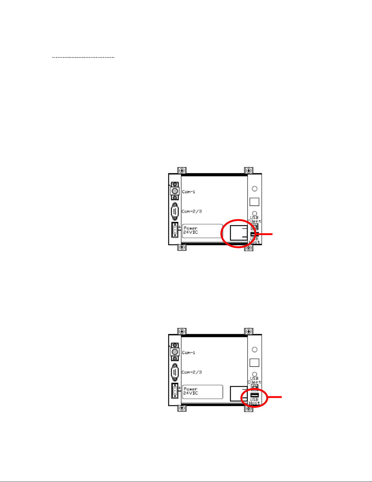
Back View of HMI Display
Battery
Back View of HMI Display
USB Host
■ Section 8
Maintenance
Clock Battery Replacement
The HMI Display Real Time Clock is maintained by a non-rechargeable battery internal to the HMI Display.
Change the battery every ten years or as needed. The system will continue to function as an active filter with
a dead battery but HMI information (fault logs and trend plots) will not be maintained between power cycles.
To replace the battery, open the battery cover on the back of the HMI Display (see Figure 8.1) and remove
the old battery. Dispose or recycle the old battery in accordance with any applicable national, state/provincial,
and local requirements. Install new battery and close battery cover.
Replacement Battery Type: 3V Lithium CR2032 x Quantity 1
Cover
Figure 8.1 – HMI Display Battery L o cation
Software Field Upgrades
In the event the HMI Display application software needs to be upgraded, the USB host port on the back panel
of the HMI Display (see Figure 8.2ftware updates provided by TCI.) can be used for field upgrades. Software
upgrade instructions will be sent with any software updates provided by TCI.
Port for
Software
Upgrades
Figure 8.2 – HMI Display USB Host Location
97
Page 98

LED
LED Color
Description (LED Color)
D1
Green
AUX 1
D3
Green
AUX 2
D4
Green
Running Relay Energized
D5
Green
Power-On Relay Energized
D6
Green
Fault Relay Energized
D7
Green
Current Limit Relay Energized
D12
Green
RS485 Communication is active from converter
D13
Orange
RS485 Communication is active to converter
D14
Green
Input Run Command Present
Troubleshooting
HarmonicGuard A ctive Filter Fault
If the display indicates a fault has occurred proceed to the fault screen by choosing the “Fault” menu screen
button. To see if this is a recurring fault hit the “History” button from inside the “Fault” screen. To clear a
fault press the “Reset” button from inside the “Fault” Screen or the “Stop” button from any screen.
Warning
Only qualified electricians should carry out all electrical installation & maintenance work on t he HGA.
Disconnect all sources of power to the drive and HGA before working on the e quipment. Do not
attempt any work on a powered HGA.
This HGA unit contains high voltages and c a pacitors. Wait at least five minutes after disconnecting
power from the filter before attempting to service the conditioner. Check for zero voltage between all
terminals on the capacitors. Also, check for zero voltage between all phases of the input and output
lines. All maintenance and troubleshooting must be done by a qualified ele c trician. Failure to follow
standard safety procedures may result in death or serious injury. Unless an external disconnect
means has been provided everything ahead of the filter circuit breaker, including the reactors,
will still be energized.
Interface Module Problem
The Interface Module is comprised of four major components; the HMI display, the Interface PCB, the
cabling and an optional Gateway. The Interface PCB contains diagnostic LEDs. The locations of the LEDs
are shown in Figure 8.3, and their functions are listed in Table 8.1.
Figure 8.3 – Communications Board LED placement
Table 8.1 – LED Functions
98
Page 99

Warning
Many electronic components located within the filter are sensitive to static electricity. Voltages
imperceptible to human touch can reduce the life, affect performance and/or destroy sensitive
electronic devices. Use proper electrostatic discharge (ESD) procedures when se rvicing the filter and
its circuit boards.
Troubleshooting Notes
• To reboot the system, remove power to the filter and Interface Module, wait a few minutes then
reapply. If this does not work check all the cable and connections, and try again. If the problem is
still not resolved replace the Interface Module assembly.
• If no buttons are pressed for 5 minutes the screen will turn off. To reactivate touch anywhere on the
screen.
• If the HMI Display shows a “COM 1 Station 1: Communication Error” across the bottom of the
screen check the serial cable between HMI Display COM1 and Interface PCB J1.
• If the HMI Display sho ws a “NO COM” indication on the system state indicator or a 7010
Communications Fault in the fault screen check the serial cable between Interface PCB J2 and the
HarmonicGuard Active filter power converter module J25 (100A/50A units) or J7 (200A units).
• For technical support contact TCI directly at 1-800-824-8282. Select "Customer Service" or
"Technical Support".
Troubleshooting Flow Chart
Figure 8.4 – Troubleshooting Flow Chart
99
Page 100

■ Section 9
Appendix – Installation Diagram
Figure 9.1 – Installation Diagram
100
 Loading...