

Page 1

®
HarmonicGuard
Series Drive-Applied Harmonic Filter
Installation, Operation, and Maintenance Manual
TCI, LLC W132 N10611 Grant Drive Germantown, Wisconsin 53022
Phone: 414-357-4480
Fax: 414-357-4484
Helpline: 800-TCI-8282
Web Site: http://www.transcoi l. c om
© 2014
Page 2

Page 3

i
T able of Contents
Introduction .............................................................................................................................. 2
Receiving Inspection and Storage ............................................................................................ 4
Pre-installation Planning .......................................................................................................... 5
Installation Guidelines ............................................................................................................. 6
HG7 Harmonic Filter Operation .............................................................................................. 7
Installation ............................................................................................................................... 8
Maintenance and Service ......................................................................................................... 9
Product Description ............................................................................................................... 13
Drawings ................................................................................................................................ 16
Standard Filter (ST) ............................................................................................................... 21
Contactor Option (STC)......................................................................................................... 22
Power Monitor Package Option (XM) ................................................................................... 23
HG7 “XM” Option Operation................................................................................................ 27
The HG2TM Protection Monitor ............................................................................................. 28
Kit Package Option (KP) ....................................................................................................... 45
Installation ............................................................................................................................. 47
Component Package Option (CP) ........................................................................................ 49
Installation ............................................................................................................................. 51
HG7 I, O, & M Manual
Page 4

INTRODUCTION
2
!
Introduction
Safety Instruc tions Over vie w
This section provides the safety instructions which must b e followed when installing, oper ating, and
servicing the HG7 harmonic filter. If neglected, physical injury or death may follow, or damage may
occur to the filter or equipment connected to the HG7 harmonic filter. The material in this chapter must
be read and understood before attempting any work on, or with, the product.
The HG7 harmonic filter is intended to be connected to the input terminals of one or more adjustable
speed drives. Three-phase power is connected to the input terminals of the HG7 and po wer is supplied
to the dri ve or drives t hrough the HG7 . The instruct ions, and p articularly the safety instruc t io ns, for the
drives, motors and any other related equipment must be read, understood and followed when working
on any of the equipment.
Warnings and Cautions
This manual provides two types of safety instructions. Warnings are used to call attention to
instructions, which describe steps, which must be taken to avoid conditions, which can lead to a
serious fault condition, physical injury or death.
Cautions are used to call attention to instructions that describe steps that must be taken to avoid
conditions that can lead to a malfunction and possible equipment damage.
Warnings
Readers are informed of situations that can result in serious physical injury and/or serious damage to
equipment with warning statements highlighted by the following symbols:
Warning
Warning
Warning
Dangerous Voltage Warning: warns of situations in which a
high voltage can cause physi cal injury and/or damage
equipment. The text next to this symbol d e scribes ways to
avoid the danger.
General Warning: warns of situatio ns that can cause physical
injury and/ or damage equipment by means other than
electrical. The text next to this symbol describes ways to avoid
the danger.
Electrostatic Discharge W arning: warns of situations in which
an electrostatic discharge can damage equipment. The text next
to this symbol describes ways to avoid the danger.
Cautions
Readers are informed of situations that can lead to a malfunction and possible equipment damage with
caution statements:
Caution
General Caution: identifies situatio ns that can lead to a
malfunction and possible equipment damage. The text
describes ways to avoid the situation.
INTRODUCTION HG7 I, O, & M Manual
Page 5

INTRODUCTION
3
!
!
!
General S afety Ins truct ions
These safety instructions are intended for all work on the HG7. Additional safety instructions are
provided at appropriate points on other sections of this manual.
Warning
Warning
Warning
Warning
Warning
Warning
Be sure to read, understand and follow all safety instructions.
Only qualified electricians should carry out all electrical
installation and maintenance work on the HG 7 harmonic fil ter.
All wiring must be in accordance with the National Electrical
Code (NEC) and/or any other codes that apply to the
installation site.
Disconnect all power before working on the equipment.
Do not attempt any work on a powered HG7 filter.
The HG7 harmonic filter, drive, motor, and other connected
equipment must be properly grounded.
After switching off the power, always allow 5 minutes for the
capacitors in the HG7 filter and in the drive to discharge before
working on the HG7, the d rive, the motor, or the connecting
wiring. It is a good idea to check with a voltmeter to make sure
that all sources of power have been disconnected and that all
capacitors have discharged before beginning work.
INTRODUCTION HG7 I, O, & M Manual
Page 6

INTRODUCTION
4
Product Family
Warranty Period
KLR, KDR
For the life of the drive with which they are installed.
One (1) year of useful service,
HG7, KH, 3H, KRF
Three (3) years from the d ate of shipment.
KCAP, KTR, KMP
Five (5) years from the date of shipment.
One (1) year of useful service,
not to exceed 18 months from the date of shipment.
Receiving Inspection and St orage
Thank you for selectin g the HG7 Drive-Applied Ha rmonic Filter. TCI has pr oduced this filter for use
in many variable speed drive applications that require input power line harmonic current reduction.
This manual describes how to install, operate and maintain the HG7 harmonic filter.
Receiving Inspection
The HG7 harmonic filter has been thoroughly inspected and functionally tested at the factory and
carefully packaged for shipment. When you receive the unit, you should immediately inspect the
shipping container and report any damage to the carrier that delivered the unit. Verify that the part
number of the unit you received is the same as the part number listed on your purchase order.
TCI Limited Warranty Policy
TCI, LLC (“TCI”) warrants to the original purchaser only that its products will be free from defects in materials
and workmanship under normal use and service for a period originating on the date of shipment from TCI and
expiring at the end of the period described below:
KLC, KLCUL, KMG,
V1k
All Other Products
The foregoing limited warranty is TCI’s sole warranty with respect to its products and TCI makes no other
warranty, representation, or promise as to the quality or performance of TCI’s products. THIS EXPRESS
LIMITED WARRANTY IS GIVEN IN LIEU OF AND EXC LUDES ANY AND ALL EXPRESS OR IMP LIED
WARRANTIES INCLUDING, WITHOUT LIMITATION, ANY IMPLIED WARRANTY OF
MERCHANTABILITY OR FITNESS FOR A PARTICULAR PURPOSE.
This warranty shall not apply if the product was:
a) altered or repaired b y anyone other than TCI;
b) applied or used for situations other than those originally specified; or
c) subjected to negligence, accident, or damage by circumstances beyond TCI’s control, including but not
limited to, improper storage, installation, operation, or maintenance.
If, within the warranty period, any product shall be found in TCI’s reasonable judgment to be defecti ve, TCI’s
liability and the Buyer’s exclusive remedy under this warranty is expressly limited, at TCI’s option, to (i) repair or
replacement of that product, or (ii) return of the product and refund of the purchase price. Such remedy shall be
Buyer’s sole and exclusive remedy. TCI SHALL NOT, IN ANY EVENT, BE LIABLE FOR INCIDENTAL
DAMAGES OR FOR CONSEQUENTIAL DAMAGES INCLUDING, BUT NOT LIMITED TO, LOSS OF
INCOME, LOSS OF TIME, LOST SALES, INJURY TO PERSONAL PROPERTY, LIABILITY BUYER
INCURS WITH RESPECT TO ANY OTHER PERSON, LOSS OF USE OF THE PRODUCT OR FOR ANY
OTHER TYPE OR FORM OF CONSEQUENTIAL DAMAGE OR ECONOMIC LOSS .
The foregoing warranties do not cover reimbursement for removal, transportation, reinstallation, or any other
expenses that may be incurred in connection with the repair or replacement of the TCI product.
The employees and sales agents of TCI are not authorized to make additional warranties about TCI’s products.
TCI’s employees and sales agen ts oral statements do not constitute warranties, shall not be relied upon by the
Buyer, and are not part of any contract for sale. All warranties of TCI embodied in this writing and no other
warranties are given beyond those set forth herein.
TCI will not accept the return of any product without its prior written approval. Please consult TCI Customer
Service for instructions on the Return Authorization Procedure.
not to exceed 18 months from the date of shipment.
Storage Instructions
If the HG7 harmonic filter is to be stored before use, be sure that it is stored in a location that conforms
to published storage humidity and temperature specifications stated in Table 2 (HG7 Harmonic Filter
Technical Specifications). Store the unit in its original packaging.
INTRODUCTION HG7 I, O, & M Manual
Page 7

INTRODUCTION
5
Pre-installation Planning
Verify th e A pplicat ion
HG7 Ratings
Make sure that the HG7 harmonic filter is correct for the a pplication. The voltage ra tings of the filter
must match t he input voltage rating o f the conne cted dr ive. T he horse power and current r atings of the
filter must be adequate for the connected load.
Select a Suitable Locat ion
Environment
Locating the HG7 in a suitable environment will help ensure proper performance and a normal
operating life. Refer to the environmental specifications listed in Table 2, marked on the unit's
nameplate and/or noted on the drawings furnished with the unit.
Warning
The unit must be installed in an area where it will not be exposed to:
♦ Direct sunlight
♦ Rain or dripping liquids (unless filter is in a 3R enclosure)
♦ Corrosive liquids or gasses
♦ Explosive or combustible gases or dust
♦ Excessive airborne dirt and dust
♦ Excessive vibration
Unless specifically labeled as approved for such use, this equipment is not
suitable for use in an explosive atmosphere or in a "Hazardous (Classified)
Location" as defined in article 500 of the National Electrical code.
Working Space
Provide sufficient access and working space around the unit to permit ready and safe installation,
operation and maintenance. Make sure that the installation conforms to all working space and
clearance requirements of the National Electrical Code (NEC) and/or any other applicable codes.
Provide sufficient unobstructed space to allow cooling air to flow through the unit.
Mounting an Open Panel Unit
If you are mounting an open panel uni t in your own encl osure, you must p rovide a n enclo sure that is
adequately sized and ventilated sufficiently to prevent overheating. The rating and dimension tables for
open panel units list the watts o f heat los s t hat is dissipated by the HG7 harmonic filter. The maximum
temperature of the air around the HG7 filter capacitors and Protection Monitor should not exceed 50°C
(122°F).
Power Wiring
When selecting a mounting loca tion for the HG7 filter, plan for the routing of the power wiring.
Route the conduit and wiring from the power source to the filter and then to the variable speed drive.
The HG7 is provided with internal fuses. Additional fuses may be required at the connecting point to
protect the tap conductors. Refer to the National Electrical Code (NEC) and/or any other applicable
codes.
INTRODUCTION HG7 I, O, & M Manual
Page 8

INTRODUCTION
6
Installa tion Guidelines
Mounting
The HG7 must be mounted vertically on a smooth, solid surface, free from heat, dampness, and
condensation.
Wiring
Cable Entry Locations
The enclosed HG7 harmonic filters are not provided with enclosure wiring knockouts. A selection can
be made at the time of installation. Typical or recommended cable entry locations are shown in the
drawings section of this manual.
Field Wiring Connection Terminals
Compression type terminals a re pr ovided for a ll field wirin g connection s. The co ntrol cir cuit terminals
will accommodate 18 AWG to 10 AWG wire and should be tightened to 7 lbs. - in. torque . The wire
size capacity ranges and tightening torque for the grounding and power terminals are listed in the
drawings and other information shipped with the unit.
Grounding
The HG7 panel equipment-grounding lug must be connec ted to the ground of the wiri ng system. T he
equipment grounding connection must conform to the requirements of the National Electric Code
(NEC) and/or any other codes that apply to the installation site. The ground connection must be made
using a wire conductor. Metallic condui t is not a suitable grounding conductor . The integrity of al l
ground connections should be periodically checked.
Power Wiring
Caution
Connect three-phase power of the appropriate voltage and current capacity to the branch circuit
protective device to the HG7 input power terminals. Note: i n large units, the input p ower cond uctors
are connected directly to the input terminals on the line reactors.
Connect the output terminals of the HG7 to the input power ter minals of the adjustable speed drive.
Note: in large units, the output po wer conductors are co nnected dir ectly to the output ter minals on the
line reactors. Refer to the adjustable speed drive installation instructions for additional information.
Use copper wire that is appropriate for the voltage and current rating of the
equipment. The wire selection must conform to the requirements of the
National Electrical Code and/or other applicable electrical codes.
For units rated less than 100 amps, use wire with an insulation temperature
rating of 60°C or higher.
For units rated 100 amps or more, use wire with an insulation temperature
rating of 75°C or higher.
INTRODUCTION HG7 I, O, & M Manual
Page 9

INTRODUCTION
7
HG7 Harmonic Filter Operation
Caution
Thoroughly check the installation befor e applying po wer and operating
the equipment for the first time.
Before Applying Power for the Fir st Time
Inspect the installation to make sure that all equipment has been completely and correctly installed in
accordance with the Installation Guidelines section of this manual.
♦ Check to see that the cooling fan(s) a re operating in units so equipped.
Operation
Since the HG7 is a passive filter, it is always operating whenever the drive is operating.
INTRODUCTION HG7 I, O, & M Manual
Page 10

8
Installation
Make sure that the installation lo c a tion will not be exposed to direct sunlight, corr osive or
Select a mounting area that will allow adequate cooling air and maintenance access.
Make sure that all wiring conforms to the requirements of the National Electric Code (NEC)
Connect the HG7 equipment-grounding lug to the system ground of the premises wiring system.
Connect three-phase power to the input terminals of the HG7, L1, L2 & L3.
Connect the output power terminals, of the HG7, T1, T2 & T3, to the input power terminals of
INTRODUCTION
Intended Audience
This manual is intended for use by all personnel responsible for the installation, operation and
maintenance of the HG7 har mo nic filt ers. Such personnel are expected to have knowledge of electrical
wiring practices, electronic components and electrical schematic symbols.
Additional Information
Caution
Installation Checklist
The following are the key points to be followed for a successful installation. These points are
explained in detail in the following sections of this manual.
This manual pro vid es gene ra l in fo r mati o n desc ri b i ng your H G7 har monic filt er .
Be sure to carefully review the more specific information that is provided by the
drawings shipped with the unit. Information provided by the drawings takes
precedence over the information provided in this manual.
The ratings, dimensions and weights given in this manual are approximate and
should not be used for any purpose requiring exact data. Contact the factory in
situations where certified data is r e quired. All data is subject to change without
notice.
combustible airborne contaminants, excessive dirt or liquids.
and/or other applicable electrical codes.
Use a properly sized grounding conductor.
the variable frequency drive.
INTRODUCTION HG7 I, O, & M Manual
Page 11

INTRODUCTION
9
Maintenance a nd Service
HG7 Harmonic Filter Reliability and Service Life
The HG7 has been designed to provide a service life that equals or exceeds the life of the variable
speed drive. It has been thoroughly tested at the factory to assure that it will perform reliably from the
time it is put into service. The following periodic maintenance is recommended to assure that the HG7
filter will always perform reliably and provide the expected service life.
Periodic Maintenance
Warning
Check to see that the installation environment remains free from exposure to excessive dirt and
contamina nts. Refer to the Pre-installation Planning section of this manual.
Check to make sure that the enclosure ventilation openings are clean and unobstructed.
Clean the air filter in units that have filtered air inlets. Clean as often as necessar y to prevent dirt build-
up from impeding air flow.
Only qualified electricians should carry out all electrical installation and
maintenance work on the HG7 filter.
Disconnect all sources of power to the drive and HG7 before working on the
equipment. Do not attempt any work on a powered HG7.
Check the o peration of the cooling fan.
Inspect the interior of the enclosure for signs of overheated components. Clean the interior of the
enclosure whenever excess dirt has accumulated.
Check the integrity of all power and ground wiring connect ions.
All electrical connectio ns must be re-torqued annually.
Troubleshooting
Warning
Note: when disconnecting wires from components and terminations, mark the wires to correspond to
their compone nt and terminal c onnection.
Only qualified electricians should carry out all electrical installation and
maintenance work on the HG7 harmonic filter.
Disconnect all sources of power to the drive and HG7 before working on the
equipment. Do not attempt any work o n a powered HG7 harmonic filter.
The harmonic filter contains high voltages and capacitors. Wait at least five
minutes after disconnecting p ower from the filter before you attempt to
service the harmonic filter. Check for zero voltage between all terminals on
the capacitors. Also, check for zero voltage between all phases of the line side
of the fuses, Fu1(a)–Fu2(a)–Fu3(a), and all input terminals L1, L2 and L3 of
the line reactor (KDR). All setup, maintenance, and troubleshooting must be
done by a qualified electrician. Failure to follow standard safety procedures
may result in death or serious injury.
Reference Drawings
When troubleshooting, refer to the drawings provided for the specific equipment. Typical drawings are
provided in this manual.
INTRODUCTION HG7 I, O, & M Manual
Page 12

INTRODUCTION
10
7.5
3
15
10
3
15
15
5
25
20
6
25
25
8
35
30
10
45
40
15
60
50
15
60
60
20
80
75
25
100
100
30
125
4
1.57
1.74
1.87
5.5
2.62
2.90
3.12
7.5
3.14
3.48
3.75
9.3
4.19
4.64
5.00
11
4.72
5.22
5.62
15
6.29
6.97
7.50
18.5
7.86
8.71
9.37
22
9.43
10.45
11.25
30
13.10
14.51
15.62
37
15.72
17.41
18.75
45
18.34
20.32
21.87
55
23.58
26.12
28.12
75
31.43
34.83
37.49
90
36.67
40.63
43.74
110
44.53
49.34
53.11
132
55.01
60.95
65.61
160
65.49
72.56
78.11
200
81.20
89.98
96.85
250
99.54
110.3
118.7
315
128.4
142.2
153.1
355
141.5
156.7
168.7
400
162.4
180.0
193.7
450
178.1
197.4
212.4
500
199.1
220.6
237.4
560
222.7
246.7
265.6
630
251.5
278.6
299.9
710
262
290
312
Fuse Specifications
Table 1a through 1d list the specifications for the LC filter power circuit fuses in the HG 7. Refer also
to the drawings and other information shipped with the unit.
Table 1a – Fuse S peci fications for HG7 240 Volt Models
HG7 Rating
(HP)
kVar
Amps Type
Table 1b – Fuse Specifications for HG7 380 – 415 Volt Models
HG7
Rating
(kW)
380V
kVar
400V
kVar
415V
kVar
Power Circuit
Fuse Ratings
Class CC Bussmann
type KTK-R
or equivalent
Class T
Bussmann
type JJS
or equivalent
Power Circuit
Fuse Ratings
Type
Class CC Bussmann
type KTK-R
or equivalent
Class T
Bussmann
type JJS
or equivalent
INTRODUCTION HG7 I, O, & M Manual
Page 13

INTRODUCTION
11
10
3
10
15
5
15
20
6
15
30
10
30
40
15
30
60
20
40
75
25
50
100
30
60
125
40
80
150
45
100
200
60
125
250
75
175
300
90
200
350
105
225
400
120
250
450
135
300
600
180
400
700
210
450
800
240
500
900
270
600
15
5
10
30
10
25
50
15
30
60
20
35
75
25
40
100
30
50
125
40
70
150
45
80
200
60
100
250
75
125
300
90
150
350
105
175
400
120
200
450
135
250
500
150
250
600
180
300
700
210
350
800
240
400
900
270
450
Table 1c – Fuse Spec ifications fo r HG7 48 0 Volt Mode ls
HG7 Rating
(HP)
kVar
Amps Type
Power Circuit
Fuse Ratings
Class CC Bussmann
type KTK-R
or equivalent
Class T
Bussmann
type JJS
or equivalent
Table 1d – Fuse S pecific ations for HG7 600 V olt Models
HG7 Rating
(HP)
kVar
Amps Type
Power Circuit
Fuse Ratings
Class CC Bussmann
type KTK-R
or equivalent
Class T
Bussmann
type JJS
or equivalent
INTRODUCTION HG7 I, O, & M Manual
Page 14

INTRODUCTION
12
Replacement Parts
If replacement parts are needed, please contact your TCI representative. To ensure that the HG7
harmonic filter continues to p erfor m to its original spec ificatio ns, replace ment parts s hould c onform to
TCI specifications.
Factory Contacts and Tech Suppor t
For technical support, contact your local TCI distributor or sales representative.
You can contact TCI directly at 800-TCI-8282. Select "Customer Service" or "Tech Support" and have
your HG7 harmonic filter namepla te information available.
INTRODUCTION HG7 I, O, & M Manual
Page 15

INTRODUCTION
13
Product Description
HG7 Drive-A pp lied Ha rmon ic F ilter
The HG7 is a drive-applied harmonic filter designed and developed by TCI to reduce the harmonic
currents drawn from the power source by variable speed drives. The HG7 is available for 240, 480, 600
(60 Hz) and 380 – 415 (50 Hz) volt systems. It is suitable for use with 3-phase diode bridge rectifier
loads such as PWM AC drives.
The HG7 is a passive f ilter connected in series with t he input terminals of a variable sp eed drive or
several drives that operate as a group. It is designed to provide a low impedance path for the major
harmonic currents demanded by the drive. The filter is a stand-alone device that can be furnished in its
own enclosure and mounted adjacent to the drive. It is also available on an open panel for mounting
within an enclosure with the drive or other equipment.
The HG7 filters consist minimally of the following features and components:
♦ A KDR input series reactor to prevent system interaction and improve filter performance.
♦ An L-C harmonic filter circuit with:
A TCI 3-phase tuning reactor specifically designed for the HG7 filter
High-endurance, harmonic-rated capacitors
♦ Bleeder resistors to ensure safe capacitor discharge upon filter shutdown.
♦ Cooling fans (on select models) to ensure adequate cooling and safe operating
temperatures.
♦ Compression terminals for ease a nd integrity of all power and control wiring.
♦ Fuses.
Nameplate Data
Figure 1 sho ws a typical HG7 harmonic filter na meplate. The follo wing information is marked on the
nameplate:
♦ Part number : encoding is explained on the following page
♦ FLA: the rate d continuous operating current (RMS amps)
♦ System Voltage: the rated 3-phase line voltage (RMS volts)
♦ Hz: the rated frequency (60 Hz/50 Hz)
♦ Phase: 3 – The HG7 filter is designed for use o nly with 3-phase power.
♦ Drawing #: outline and mounting dimension drawing number
♦ Schematic #: schematic diagram drawing number
♦ Manufacturing #: for TCI i nt ernal use
♦ Enclosure Type: UL designation or "Open" panel construction
Figure 1 – Typical HG7 Harmonic Filter Nameplate
INTRODUCTION HG7 I, O, & M Manual
Page 16

INTRODUCTION
14
Part Number Encoding
Figure 2 identifies the significance of each character in the HG7 part number. The example part
number, HG250AW00ST designates a HG7 filter that is rated 75 kVar, 480 volts, 60 Hz. It includes a
standard 10% reacto r, is t u ned to the 5th har monic, i s an open panel and is designed for use with a 250
HP drive.
Figure 2 – HG7 Part Number Encoding
INTRODUCTION HG7 I, O, & M Manual
Page 17

INTRODUCTION
15
Product Technical Specifications
Table 2 lists the major technical specifications for the HG7 Harmonic Filter.
Table 2 – HG7 ST and STC Opti on Harmo nic Filte r Tec hnical S peci fications
Voltage ratings 240, 480 and 600 V, 3 ph, 60 Hz
380 – 415 V, 3 ph, 50 Hz
kVar ratings 3 to 270 kVar depending on voltage.
Load types 3-phase diode bridge rectifier loads such as PWM AC drives
Load power range 7.5 -900 Hp depending on voltage, 4–710kW
See Rating and Dimension tables.
Current ratings The include d series reactors can tolerate 200% of rated current for at
least 3 minutes.
SCCR (short circuit current
rating)
Maximum elevation 3,000 feet (1,000 meters) as standard.
Maximum ambient operating
temperature
Maximum ambient storage
temperature
Maximum humi d it y,
operating or storage
Enclosure options UL Type 1 enclosure
Agency approvals or
certifications
Standard r ating is 10kA.
50°C (122°F) – Open Panel; 40°C (104°F) – Enclosed Panel.
Product must be equipped with special cooling provisions for
operation above this temperature.
60°C (140°F)
95%, non-condensing.
UL Type 3R enclosure
UL and cUL Listed to UL508A
Insertion Impedance +/- 10% at full load current
Fusing and protection: All units have internal fuse prote c tion for the harmonic filter circuit.
Capacitors Oil filled high endurance design (no PCBs)
INTRODUCTION HG7 I, O, & M Manual
Page 18

16
Drawings
INTRODUCTION
Typical Schematic Diagrams and Outline and Mounting Dimension Drawings
Typical HG7 drawings are provided on the following pages. These drawings provide general
information describing your HG7 harmonic filter. More specific information is provided by the
drawings shipped with the unit. Be sure to carefully review the information on the provided drawings.
The information on the drawings provided with the filter takes precedence over the information
provided in this manual.
Schematic Diagrams
The schematic diagram shows the details of the HG7 circuitry. The power circuit schematic shows the
variations in input and output power connections.
Outline and Mounting Dimension Drawings
Outline and mountin g dimens ion drawin gs show the overal l enclos ure dimen sions, the c onduit ac cess
areas and the wiring connection points. The major internal components are shown pictorially.
Additional Typical Drawings
Some additional typical drawings are available for downloading at http://www.transcoil.com.
INTRODUCTION HG7 I, O, & M Manual
Page 19

INTRODUCTION
17
Typical Drawings continued
INTRODUCTION HG7 I, O, & M Manual
Page 20

INTRODUCTION
18
HG7 ST Typical Schematic based on 480V
HG7 STC Typical Schematic based on 480V
When possible, the “Up to Speed” Auxiliary Contacts should be used instead of the “Run-Stop” Auxiliary
Contacts on the VFD. Det ail ed note below.
INTRODUCTION HG7 I, O, & M Manual
Page 21

INTRODUCTION
19
HG7 XM Schematic: 7.5 – 60 HP based on 480V
When possible, the “Up to Speed” Auxiliary Contacts should be used instead of the “Run-Stop” Auxiliary
Contacts on the VFD. Det ail ed note below.
HG7 XM Schematic: 200 – 400 HP based on 480V
When possible, the “Up to Speed” Auxiliary Contacts should be used instead of the “Run-Stop” Auxiliary
Contacts on the VFD. Det ail ed note below.
INTRODUCTION HG7 I, O, & M Manual
Page 22

INTRODUCTION
20
HG7 XM Schematic: 450 – 600 HP based on 480V
When possible, the “Up to Speed” Auxiliary Contacts should be used instead of the “Run-Stop” Auxiliary
Contacts on the VFD. Det ail ed note below.
NOTE 1 Detail:
When possible, t he “Up t o Speed” Aux iliar y Contac ts s hould be use d inste ad of the “R un-S top” Aux iliar y Contac ts
on the VFD.
Benefits of this setup:
1. Most electrical systems have generator back-up systems today. The filters will start-up with no
capacitance in the circuit. On generator applications this allows the voltage regulator and the load to
stabilize before the capaci tors are brought int o the circuit elim inating spiking and potent ial leading power
factor condition.
2. This will potentially prevent a leading power f ac tor c on dit ion on the B us , es pecially when many VFDs with
filters are on the sam e Bus. For ex ample, if the VFD at speed refer ence is programmed f or 45 hertz, the
contactor is open at speeds less than 45Hz. The capacitors will be off-line when the frequency drops
below this reference. The capacitors will be closed above the 45Hz programmed contact closure for
normal harmonic mitigation.
On variable torque fan and pump loads the current drops dramatically below a 60 hertz operation and as
a result there will be too many vars of capacitance in the system for the load applied. The result will lead
to a high voltage condition at the input terminals of the VFD, potentially causing an “overvoltage” trip.
INTRODUCTION HG7 I, O, & M Manual
Page 23

CONTACTOR & CPT OPTION
21
Standard Filter (ST)
The Standard Package has the suffix of “ST” in the part number and includes very high quality
harmonic-grade capacitors and line reactors. This filter will meet the majority of application
requirements found today. This cost effective product is available as an open panel version, in a UL
Type 1 enclosure, or in an U L Type 3 R enclos ure. The open panel is perfect for inclusion in a MCC
section or easy installation into industry standard enclosures. The UL Type 1 enclosed units maintai n
the same vertical profile as the open panel design. This design is perfect for applications where floor
space is at a premium. The UL Type 3R enclosure protects the filter from harsh conditions.
Product Description
HG7 Standard Harmonic Filter
The HG7 harmonic filter is a d rive-applied harmonic filter designed and developed by TCI to reduce
the harmonic currents drawn from the power source by variable speed drives. The HG7 Standard
harmonic filter is for 200/208, 230/240, 460/480 volt or 575/600 volt systems (60 Hz) or 380 – 415
Volt systems (50 Hz). It is suitable for use with 3-phase diode bridge rectifier loads such as PWM AC
drives.
The HG7 harmonic filter is a passive filter connected in series with the input terminals of a variable
speed drive or several drives that operate as a group. It is designed to provide a low impedance path for
the major harmonic currents demanded by the drive. The filter is a stand-alone device that can be
furnished i n its o wn enc losur e and moun ted ad jac ent to the drive. It is also available on an open panel
for mounting within an enclosure with the drive or other equipment.
The HG7 Standard consists of the followin g standard featur es and components.
♦ A KDR input series reactor to prevent s ystem interaction and improve filter
performance.
♦ An L-C harmonic filter circuit with:
A TCI 3-phase tuning reactor specifically designed for the HG7
High-endurance, harmonic-rated capacitors
♦ Bleeder resistors to ensure safe capacitor discharge upon filter shutdown, located on
capacitors.
♦ Cooling fans (on select models) to ensure adequate cooling and safe operating
temperatures.
♦ Control Power transformer on enclosed units requiring auxiliary cooling fans.
♦ Compression terminals for ease and integrity of all power and control wiring.
♦ Fuses
CONTACTOR & CPT OPTION HG7 I, O, & M Manual
Page 24

CONTACTOR & CPT OPTION
22
Contactor Option (STC)
STC Option Models
This model is identified by the suffix “STC” in the part number. The STC version provides a contactor,
control power transformer and connection terminals in the filter trap circuit which allows the VFD user
to control the insertion of the HG7 filter’s trap circuit through the use of a relay contact in the drive. It
is recommended that the drive contact be programmed to open the contactor below 33% motor power.
For variable torque (fan) loads this will be approximately below 70% speed, so the at-speed contact
may be used. This reduces the possibility of leading power factor interacting with other devices on the
power system and enables the user to perform trap circuit maintenance wi thout shutting down the
entire drive system.
Product Description
HG7 STC Option Harmonic Filter
The HG7 harmonic filter is a d rive-applied harmonic filter designed and developed by TCI to reduce
the harmonic currents drawn from the power source by variable speed drives. The HG7 STC option
harmonic filter is for 200/208, 230/240, 460/480 volt or 575/600 volt systems (60 Hz) or 380 –
415Volt systems (50 Hz). It i s suitable for use with 3-phase diode br idge rectifier loads such as PWM
AC drives.
The HG7 harmonic filter i s a passive filter connected in series with the input terminals of a variable
speed drive or several drives that operate as a group. It is designed to provide a low impedance path for
the major harmonic currents demanded by the drive. The filter is a stand-alone device that can be
furnished i n its o wn enc losur e and mounted adjacent to the drive. It is also available on an open panel
for mounting within an enclosure with the drive or other equipment.
The HG7 STC Option consists of the following standard features and components.
♦ A KDR input series reactor to prevent system interaction and improve filter performance.
♦ An L-C harmonic filter circuit with:
A TCI 3-phase tuning reactor specifically designed for the HG7
High-endurance, harmonic-rated capacitors
♦ Bleeder resistors to ensure safe capacitor discharge upon filter shutdown, located on
capacitors.
♦ Filter enable/disable contactor with protection and drive interlock provisions.
♦ Cooling fans (on select models) to ensure adequate cooling and safe operating
temperatures.
♦ Control transformer for fan and control voltage power.
♦ Compression terminals for ease a nd integrity of all power and control wiring.
♦ STCH Option has heater.
CONTACTOR & CPT OPTION HG7 I, O, & M Manual
Page 25

POWER MONITOR PACKAGE ONLY
23
Po wer Monitor Pac kage Option (XM)
This model is identified by the suffix “XM” in the part number. The "XM" Option HG7 filters are
similar to the standard series HG7, but they have features and characteristics that are beyond the scope
of the “Standard” series HG7. In the rating and dimension tables we list the sizes of the “XM” option
units only to avoid confusion. T his manual is inte nded to b e used as a genera l guide to the installatio n,
operation, and maintenance of “XM” Option filters.
Product Description
HG7 “XM” Option Harmonic Filter
The HG7 harmonic filter is a d rive-applied harmonic filter designed and developed by TCI to reduce
the harmonic currents drawn from the power source by variable speed drives. The HG7 “XM” option
harmonic filter is for 200/208, 230/240, 460/480 volt, 575/600 volt systems (60 Hz) and 380 – 415
volt systems (50 Hz). It is suitable for use with 3-p hase diode bridge rectifier loads such as PWM AC
drives and 3-phase controlled rectifier (SCR or thyristor) loads such as DC drives.
The HG7 har monic filte r is a passi ve filter connected in series with the input terminal s of a variable
speed drive or several drives that operate as a group. It is designed to provide a low impedance path for
the major harmonic currents demanded by the drive. The filter is a stand-alone device that can be
furnished in its own enclosure and mounted adjacent to the drive. It is also available on an open panel
for mounting within an enclosure with the drive or other equipment.
The HG7 “XM” Option consists of the following standard features and components.
♦ A KDR input series reactor to prevent system interaction and improve filter performance.
♦ An L-C harmonic filter circuit with:
A TCI 3-phase tuning reactor specifically designed for the HG7
High-endurance, harmonic-rated capacitors
♦ Bleeder resistors to ensure safe capacitor discharge upon filter shutdown, located on
capacitors.
♦ Filter enable/disable contactor with protection and drive interlock provisions.
TM
♦ The HG2
standard in H G7 “XM” option filters rated over 20kVar to 120 kVar in capacitance. It
includes:
♦ Filter Enabled and Blown Fuse indicating lights are included as standard in filters rated
20 kVar and under, or over 120 kVA in filter capacitance rating.
♦ Cooling fans (on select models) to ensure adequate cooling and safe operating
temperatures.
♦ Control transformer for fan and control voltage power
♦ Compression terminals for ease a nd integrity of all power and control wiring.
Protection Monitor and Harmonic Power Factor Meter is included as
Three-character LCD display
Filter Disabled and Filter Enabled status indic ating LEDs
UP, DOWN, and SELECT keys
Fault Alarm Relay with form C contact for customer use
POWER MONITOR OPTION HG7 I, O, & M Manual
Page 26

POWER MONITOR PACKAGE ONLY
24
Product Technical Specifications
Table 3 lists the major technical specifications for the HG7 “XM” Option filter product:
Table 3 – HG7 “XM” Opti on Ha rmonic Fi lter Tech nical Spe cifica tions
Voltage ratings 240, 480 and 600 V, 3 ph, 60 Hz
380 – 415 V, 3 ph, 50 Hz
kVar ratings 3 to 120 kVar, 140 to 270 kVar depending on voltage.
Load types 3-phase diode bridge rectifier loads such as PWM AC drives
Load power range 7.5 - 400 HP, 500 - 900 Hp depending on voltage. See Rating and
Dimension tables.
Current ratings The included series reactors can tolerate 200% of rated current for at
least 3 minutes.
SCCR (short circuit current
rating)
Maximum elevation 3,000 feet (1,000 meters) as standard. Product must be equipped with
Maximum ambient operating
temperature
Maximum ambient storage
temperature
Maximum humi d it y,
operating or storage
Enclosure options Standard: UL Type 1 enclosure
Agency approvals or
certifications
Standard rating is 10kA.
special cooling provisions for o peration above this altitude.
50°C (122°F) – Open Panel; 40°C (104°F) – Enclosed Panel.
Product must be equipped with special cooling provisions for
operation above this temperature.
60°C (140°F)
95%, non-condensing.
UL and cUL Listed to UL508A and CSA-C2.2 No. 14
Insertion Impedance +/- 10% at full load current
Fusing and protection: All units have internal fuse prote c tion for the harmonic filter.
HG2 Protection Monitor is standard in units rated over 20 kVar.
LCD display
(units with HG2 Monitor)
Status indication LEDs
(units with HG2 Monitor)
Fault relay
(units with HG2 Monitor)
Pilot lights
(Units w/o HG2 monitor)
Capacitors Oil filled high endurance design (no PCBs)
POWER MONITOR OPTION HG7 I, O, & M Manual
Operating Parameter values: kW, kVA, power factor, voltage,
current, harmonic voltage, current, and total harmonic distortion
Faults: low current trip, high curre nt trip, time delay over-current trip,
door interlock, over-temperature, multi-unit e xternal, and interlock
faults.
Setup Parameters: filter nameplate ratings, fault & re set delays, and
trip levels.
Green LED indicates: Filter Enabled
Red LED indicates: Filter Disabled
De-energized when a fault is detected.
Form C contact for customer use; rated 5 A at 120 VAC & 5 VDC.
Blown Fuse indica ting lights for 3-phase filter fuses
Filter Enabled pilot light
Page 27

POWER MONITOR PACKAGE ONLY
25
Control Wiring
Control Power
An internal control power transformer is provided to supply 120 VAC single-phase power for the
contactor, Protection Monitor, and cooling fan(s). Fuses are provided on both the primary and
secondary sides of the control transformer.
Filter Enable Input
An auxiliary N.O. run contact from the drive should be connected to the Filter Enable input to enable
the HG7 “XM” Option only when the drive is r unning.
Fault Alarm Relay
A Fault Alarm relay is included in the HG2 Protection Monitor which is furnished as standard in
“XM” Option units rated over 20 kVar. The Fault Alarm relay is energized when control power is
applied to the HG7 and the HG7 is operating properly. A set of form C contacts is provided for
customer use.
Determine how the Fault Alarm contact will be used. It may be connected to the drive external fault
input or to some supervisory control or alarm annunciation equipment. A HG7 fault alarm i ndicates
that the HG7 filter has been disabled by the HG2 Protection Monitor. If the drive operates while the
HG7 is disabled, increased harmonic distortion of the power source may have adverse effects on the
power distribution system components and other equipment. To guard against the effects of increased
harmonic distortion, consider connecting the HG7 to automatically shut down the drive if a fault
occurs. T he best alternat ive to shuttin g down the dr ive is to provide an alarm to personnel who will
promptly investigate the problem.
POWER MONITOR OPTION HG7 I, O, & M Manual
Page 28

POWER MONITOR PACKAGE ONLY
26
Connection Diagram
Figure 3 shows the typical wiring connections between the HG7 and the drive. Refer to the drawings
furnished with the HG7 for mor e sp e c ific in formation. Refer also to the instructions for the drive and
other equipment to which t he Enable Input and the Fault Al arm contact are connected.
Figure 3
–
Typical Connection Dia gram
For HG7 Harmonic Filters with the “XM” Option:
When connecting input power conductors directly to the input line reactors in the HG7 “XM”
Option units, the cond uc tor s must be passe d thr oug h the c urrent tra nsfo r mers t hat are prov ided
for use by the HG2 Protection Monitor. Units below 75 kVar and above 120 kVar do not have
current transformers.
Control Wiring
Connect the HG7 “XM” Option Filter Enable input (terminals 1 and 2) to an auxiliary N.O. Run
contact in the adjustable speed drive. Connecting a Drive Aux Run contact will automatically connect
the HG7 whe never t he drive is running. If a jumper is connected between terminals 1 and 2, the HG7
will be connected whenever the drive branch circuit power disconnect device is closed. Connect the
HG7 Fault Ala rm relay contacts to the app ropriate fault monitorin g circuit. It may be con nected to the
drive or to some supervisory control or alarm annuncia tion equipment. T he fault contact is par t of the
HG2 Protection Monitor, which is provided as standard in HG7 “XM” Option units lar ger than 20
kVar.
POWER MONITOR OPTION HG7 I, O, & M Manual
Page 29

POWER MONITOR PACKAGE ONLY
27
HG7 “XM” Option Op erat ion
Adjustments
Protection Monitor Settings
♦ The Protection Monitor Setup Parameters and calibration adjustments are factory set and
should not be changed except as directed in the troubleshooting procedures.
♦ The protection monitor is described in detail in the following section of this manual.
Start Up (Commissioning)
Caution
Before Applying Power for the Fir st Time
Inspect the installation to make sure that all equipment has been completely and correctly installed on
accordance with the Installation Guidelines section of this manual.
Before Operating the Drive for the First Time
♦ For units equipped with the HG2 Protection Monitor, check to see that the HG2 operates
as described in the HG2 Power Up Sequence
♦ For units equipped with pilot lights, the Blown Fuse lights should be off. The Filter
Enabled light should be off unless the Enable Input has been jumpered rather than
connected to a Drive Aux Run contact.
♦ Check to see that the cooling fan(s) a re operating in units so equipped.
Thoroughly check the installation befor e applying po wer and operating
the equipment for the first time.
POWER MONITOR OPTION HG7 I, O, & M Manual
Page 30

POWER MONITOR PACKAGE ONLY
28
The HG2TM Protection Monitor
Introduction
Product Description
The HG2TM Protection Monito r is included as standard in HG7 “XM” Option models rated over 20
kVar. The HG2 monitors the HG7 operation, electronically protects the power circuits, displays
performance information, and provides a control interface with the drive and/or supervisory control
system. A three-character display is provided with UP, DOWN, and SELECT keys and two status-
indicating LEDs.
The HG2 includes analog inputs for monitoring the line voltage and current and the current in the
harmonic filter. Current transformers are included in HG7, “XM” Option harmonic filter units to
provide the line current inp uts. Sense wind ings from in the t uning reactor p rovide the sour ce for the
current measurements. Voltage is measured through direct input to the HG2.
The HG2 Protection Monitor provides a local display for power monitoring at the point where the HG7
filter is connected to the power distrib ution system. The power monitoring displa y selections include
line voltage, current, real power (kW), apparent power (kVA), power factor, and harmonic distortion
parameters. The harmonic distortion parameters include total harmonic distortion (%THD) of the line
voltage and current as well as indivi dual values of low ord er harmonics. Filter curr ent and harmo nic
values are also available. Three-phase average parameter values, totals, and individual phase values are
available. The HG2 calculates parameter values from the signals available at the analog inputs.
The HG2 inc ludes co ntact clo sure inp uts for F ilter Enable control and for optional Over-temperature
and Door Interlock prote ction functions. A serial interlo ck connection is pr ovided for coo rdinating the
protection functions of multiple HG2 Protection Monitors.
The HG2 Protection Monitor provides fault protection for the filter by disconnecting the capacitor
banks when a fault is detected. Protection functions include filter over and under-current, door
interlock, o ver-temperature, and others. Note that the doo r interlock switch a nd the over-temperature
thermostatic switch are optional. Fault Codes are generated on the display for ease of troubleshooting.
POWER MONITOR OPTION HG7 I, O, & M Manual
Page 31

POWER MONITOR PACKAGE ONLY
29
No.
1
Display
LCD
Displays “OFF” when filter is off.
Displays Fault Code (Fnn) when a fault condition exists.
2
Filter Disabled
Red LED
Illuminated when filter is disabled by fault trip.
3
Filter Enabled
Green LED
Illuminated when filter is operating.
UP
(Scroll)
scroll to desired parameter selection.
(Scroll)
6
SELECT
Key
Press and release quickly to display L #, L A, or L r, phase,
desired selection.
Figure 4 – HG2 Protection Monitor Displ ay a nd Keypad
Display and Keypad
Figure 4 shows the HG2 Protection Monitor display and keypad. Table 4 lists the vario us component
items and describes their functions.
Table 4 – HG2 Protec tion Monitor Displ ay and Key pad Features
Item
4
5
Name Description Function
Displays the value of the selected Operating Parameter.
Key Press and release quickly to display the name of the
selected parameter. Display automatically reverts to
DOWN
Key
parameter value display after 1 second. Press and hold to
average, or total value selection. Press and hold to scroll to
POWER MONITOR OPTION HG7 I, O, & M Manual
Page 32

POWER MONITOR PACKAGE ONLY
30
General Operation
Power Up Sequence
♦ For the first 3 seconds after power is applied the display will show “888.”
♦ After the first 3 seconds and until the reset lockout time (parameter 1A, 30 sec. Default)
has expired, the display will show “OFF.”
♦ When the reset lockout time has expired:
If the Enable input is open and no fault exists:
The red Filter Disabled LED will be off.
The green Filter Enabled LED will b e off.
The display will show “OFF.”
If the Enable input is open and there is an external, over-temperature, or serial data fault:
The red Filter Disabled LED will be on.
The Fault Alarm r elay will be energized.
The green Filter Enabled LED will b e off.
The display will show "F01," "F03," or "F04" for the respective faults.
If the Enable input is closed and no fault exists:
The red Filter Disabled LED will be off.
The green Filter Enabled LED will be on.
The contactor will pull in connecting t he filter.
The display will show the value of the selected Operating Parameter.
If the Enable input is closed and a fault exists:
Initially, t he green Filter Enabled LED will be on and the contactor will pull in
connecting the filter until the fault is dete c te d.
Once the fault is detected:
The red Filter Disabled LED will be on.
The Fault Alarm r elay will be energized.
The green Filter Enabled LED will b e off.
The display will show a Fault Code, F01 to F31.
Normal Operation
The filter should operate whenever the drive operates. When the drive starts, a Drive Aux Run contact
should close the HG7’s Filter Enable input . After the reset lockout time has expired, the green Filter
Enabled LED will turn on and the contactor in the HG7, “XM” Option will connect the filter. The
display will show the value of the selected Operating Parameter.
When the d rive stops, a Drive Aux Run contact should open the filter’s Enable input. The gre en Filter
Enabled LED will turn off and t he contactor in the HG7 will disco nnect the filter. The display will
show "OFF."
Changing the Displayed Parameter
During operation, the HG2 displays the value of the selected Operating Parameter. The Operating
Parameters are listed in Table 5. When the UP or DOWN key is pressed and immediately released, the
display shows the parameter name for approximately 1 second and then reverts to displaying the
parameter value. To change to the next or previous parameter, press the UP or DOWN key and release
the key as soon as the parameter name changes. Holding down the UP or DOWN keys will scroll
through parameters forward or backward, respectively.
When the SELECT key is pressed and immediately released, the display shows "L 1," "L 2," "L 3,"
“L A,” or " L r," for approximately 1 second and then reverts to displaying the parameter value. "L A,"
POWER MONITOR OPTION HG7 I, O, & M Manual
Page 33

POWER MONITOR PACKAGE ONLY
31
OFF
Not in run and no faults
A
Line Current (total RMS amps)
C
Filter current (total RMS amps)
A H
Line harmonic current distortio n
(% THD)
C H
Filter harmonic current distor tion
(% THD)
A 1
Line 1st harmonic current
(fundamental RMS amps)
C 1
Filter 1st harmonic current
(fundamental RMS amps)
A 5
Line 5th harmonic current
(RMS amps)
C 5
Filter 5th harmonic current
(RMS amps)
A 7
Line 7th harmonic current
(RMS amps)
(RMS amps)
(RMS amps)
C11
Filter 11th harmonic current
(RMS amps)
A13
Line 13th harmonic current
(RMS amps)
C13
Filter 13th harmonic curre nt
(RMS amps)
P
Real Power (kW)
U
Line voltage L-N (total RMS volts)
volt system
U A
Apparent Power (kVA)
U H
Line harmonic voltage distortio n
(% THD)
PF
Power Factor (%)
U 1
Line 1st harmonic voltage
(fundamental RMS volts)
*L A
Average value
(RMS volts)
(RMS volts)
U11
Line 11th harmonic voltage
(RMS volts)
*L 2
Line 2 value
U13
Line 13th harmonic voltage
(RMS volts)
*L 3
Line 3 value
indicates that the displayed value is the average of the individ ual phase val ues. "L 1," "L 2," & "L 3"
indicate the display of individual phase values. "L r," indicates that the displa yed value is the total of
the phase values. To change the "L *" selection, press and hold the SELECT key to scroll to the desired
selection. The "L 1," "L 2," & "L 3" selections are available for all of the parameters. The “L A”
selection is available for Filter Current “C,” Line Voltage “U,” Line Current “A” and Power Factor
“PF.” The "L r” selection is available for Real Power “P” and Apparent Power “UA.”
Table 5 – Operating Parameter Display
Parameter
Name
Parameter Value
Parameter
ID
Parameter Value
C 7 Filter 7th harmonic current
L-N approx. 277 for a 480 volt
system and approx. 139 for a 240
U 5 Line 5th harmonic voltage
U 7 Line 7th harmonic voltage
A11 Line 11th harmonic current
*L r Total value
*L 1 Line 1 value
* These functions are accessible by pressing the SELECT key.
Fault Detection
If a fault condition is d etected by the HG2, the red Filter Disabled LED will t urn on and the Fault
Alarm relay will be energized. T he green Filter Enabled LED wil l turn off and t he contactor i n the
HG7 will disconnect the filter . The display will show a Fault Code, F001 to F31 as listed in Table 6. In
order to minimize nuisance trips, time delays are applied to some fault conditions as indicated in the
table.
When the fault condition has been corrected, press the UP and SELECT keys simu ltaneously t o clear
the fault. When the fault reset clear time has expired, the red Filter Disabled LED will tur n off a nd t he
Fault Alarm relay will be de-energized. The green Filter Enabled LED will turn on, the contacto r will
connect the filter and the display to the selected Operating Parameter.
In a system wit h mul tip l e uni t s, an y u nit ma y d ete c t a fa ult a nd s hut d o wn the whole system. The other
units in the system will displa y “F01,” External F ault, and turn off. The faul t may onl y be clea red by
POWER MONITOR OPTION HG7 I, O, & M Manual
Page 34

POWER MONITOR PACKAGE ONLY
32
F01
External Fault (multiple boards in a series line)
F02
Door Open In Run Mode (no delay)
F03
Overtemp (6 sec. delay)
F04
Serial Data Fault (8 sec delay)
F11
Filter Current Low Trip Line 1 (20 sec. delay)
F12
Filter Current Low Trip Line 2 (20 sec. delay)
F13
Filter Current Low Trip Line 3 (20 sec. delay )
F21
Filter Overcurrent Fast Trip Line 1
F22
Filter Overcurrent Fast Trip Line 2
F23
Filter Overcurrent Fast Trip Line 3
F31
Filter Overcurrent Delayed Trip Line 1 (delay set by parameter 1A)
F32
Filter Overcurrent Delayed Trip Line 2 (delay set by para met er 1A)
F33
Filter Overcurrent Delayed Trip Line 3 (delay set by parameter 1A)
resetting the unit that detected the fault condition. The other units in the system will be clear
automatically when the faulted unit i s r e set.
Table 6 – Fault Code Dis play
Fault Code Fault Description
Setup Parameters
Introduction
The Setup Parameters are used to enter the nameplate data required for matching the HG2 to the HG7
harmonic filter ratings. Fault trip levels and delay times are also adjustable. A security code can be
entered to prevent unauthorized access to the Setup Menu. The Calibration Mode is accessible through
the Setup Menu (See HG2 Protection Monitor Calibration). Table 7 describes the Setup Parameters,
indicates the adjustment ranges, and lists the factory default settings The Protection Monitor Setup
Parameters a nd calibration adjustments are factory set and should not be changed except as directed in
the troubleshooting procedures.
Setup Procedure
1. With the power off and no over-temperature fault condition, hold down all thre e keys (UP,
DOWN, and SELECT) while applying power. Hold for 5 seconds after power is applied.
2. Release all three keys. The display will show “000”.
3. If the security code has not been changed from the Factory Default of “000” go to step 5.
4. If the security code is not "000," press the DOWN key to enter the security code for digit one.
Press the UP key once to select digit two. Press the DOWN key to enter the code for digit two.
Press the UP key once to select digit three. Press the DOWN key to enter the code for digit three.
5. P ress and release the SELECT key. The display will show “---” if the code is correct, or “OFF” if
the code is not correct. If the incorrect code has been entered, start over at step 1.
6. P ress and release the UP key. “1A” will be displayed.
7. P ress and release the SELECT key to display the parameter setting.
8. When the setting of a selected parameter is displayed, pressing the UP and DOWN keys will
increase and decrease the setting.
9. P ress and release the SELECT key to store the setting and return to the menu.
10. Press and release the UP key to display the next parameter on the Set up Menu.
11. To exit setup, use the UP key to ste p through the menu past paramete r "11A" to “---”, then press
the SELECT key.
POWER MONITOR OPTION HG7 I, O, & M Manual
Page 35

POWER MONITOR PACKAGE ONLY
33
---
Enter/Exit Factory Setup Mode
1 A
Fault Delay Time
1-60 SEC
30
2 A
Restart Lockout Time
1-60 SEC
30
3 A
Filter KVAR Rating (Nameplate)
3.0-120 KVAR
(Nameplate)
4 A
Operating Frequency (Nameplate)
50 or 60 Hz
(Nameplate)
5 A
Fast Trip Overcurrent % Set
100%-199%
180
6 A
Slow Trip Overcurrent % Set
100%-199%
160
7 A
Low Trip Undercurrent % Set
1%-100%
80
8 A
Nominal Line to Line Voltage (Nameplate)
200 - 600 VOLTS
(Nameplate)
9 A
Line Current Rating (Nameplate)
0 or 5 - 480 AMPS
(Nameplate)
10A
Security Code
000 – 999
000
1 = Calibration Mode
NOTE:
If the code is changed and the new code is lost, you will no longer have
12. You can step thro ugh the menu only in the "UP" di rection. If you wish to return to a n item once
you have stepped past it, step past "---" without pressing the SELECT key to retur n to "1A."
Table 7 – Setup Menu
Parameter
Name
Description Range
Factory
Default
Setting
11A
Calibration Mode
0 = Normal Operation
0
Changing the Security Code
The factory default security code is “000.” To change this code, enter the Setup Menu and proceed as
follows:
13. Use the UP key to step to parameter “10A.”
14. P ress and release the SELECT key. The present security code will be displayed.
15. Use the DOWN key to change digit one to the first digit of t he new code.
16. Press the UP key once to select digit two.
17. Press the DOWN key to change digit two to the second digit of the new code.
18. Press the UP key once to select digit three.
19. Press the DOWN key to enter digit three to the third digit of the new code.
20. Press the UP key once and the original code will be disp layed.
21. Repeat the steps 3 to 7 to enter the new code a second time.
22. After completing step 7, press the SELECT key.
23. If the new code has been properly entered twice, the display will show “10A” and the new code
will be saved.
24. If the two entries of the new code did not agree, "err" will be displayed. Press any key and the
display will show “10A.” If you press and release the SELECT key, you can see that the code
remains unchanged. You can start over at step 3.
access to the Setup Menu. The unit will have to be returned to the factory to
be reprogrammed to the default security code.
POWER MONITOR OPTION HG7 I, O, & M Manual
Page 36

POWER MONITOR PACKAGE ONLY
34
Troubleshooting Units Equipped with the HG2TM Protection M onitor
The HG2TM Protection Monitor and Harmonic Power Factor Meter is included as standard in HG7
“XM” option filters rated over 20 kVar. Units rated 20 kVar and less have Blown Fuse and Filter
Enabled pilot lights to indicate their operating status and ar e not equipped with the HG2 as sta ndard.
Troubleshooting information for pilot light equipped units is provided in the following section under
the heading Troubleshooting Units Equipped with Pilot Lights.
Normal Operation
The normal operation of the HG2 protection monitor is described in detail in the HG2 Protection
Monitor section of this manual. Refer also to HG2 Protection Monitor Calibration including figure s 5,
6 and 7.
Protection Monitor Display and Status L ights
During Normal Operation, the green Filter Enabled LED should be on, the red Filter Disabled LED
should be off and the display should show the selected Operating Parameter.
If the HG2 display is blank and no LEDs are illuminated, the possible causes include:
♦ If the drive is also inoperable and lacking any "Power On" indications:
Three-phase power has probably been disconnected either manually or by the operation
of a protective device. Check the main disconnect and fuses or circuit breaker. If fuses
have blown or a breaker has tripped, a short circuit or severe overload condition has
probably occurred in the HG7 filter, drive, motor, or power wiring. Check for evidence of
damaged, b urned, or overheated wiring or components.
♦ If the drive appears to be receiving power:
Check the primary and secondary control power transformer fuses in the HG7 filter.
If a fuse has blown, there is probably a short circuit, ground fault, or overload
condition in the HG7. Check for evidence of damaged, burned, or overheated wiring
or components.
Check the following items:
Control circuit wiring
Control circuit transformer
Cooling fan
HG2 Protection Monitor
If the fuses are good, the HG2 may be defective
If drive is operating but the HG2 display shows OFF, the red Filter Disabled LED is on and the
green Filter Enabled LED is off:
♦ Check the Filter Enable input to the HG2.
If the Filter Enable input is open, the Drive Aux Run contact may be open or
disconnected.
If the Filter Enable input is closed, the HG2 may be defective.
POWER MONITOR OPTION HG7 I, O, & M Manual
Page 37

POWER MONITOR PACKAGE ONLY
35
F01
External Fault
J1-10.
F02
Door Interlock Fault
Troubleshoot by verifying conti nuity betw een J6-1 & J6-8.
F03
Over-temperature Fault
Troubleshoot by verifying continuity at the Protection Monitor between J6-1 & J6-6.
F04
Serial Interlock Fault
Protection Monitor between J1-8 & J1-10.
Protection Monitor Display Fault Codes
If the Protection Monitor display shows a Fault Code (F01 to F33), follow the troubleshooting
procedure provided in Table 8. If a Fault Code is displayed, the Filter Disabled LED will be
illuminated and the Fault Alarm R e lay will be de-energized.
Table 8 – Fault Code Trou bles hooting Pr ocedur es
FAULT
Code
This Fault Code indicates a fault in an HG7unit other than the one displaying the "F01"
Fault Code.
In a system that has multiple sections, each monitored with an HG2, any HG2 may detect
a fault and in turn disconnect all the harmonic filters linked via the serial connection. The
unit detecting the fault will display the appropriate Fault Code while all others in the series
will display “F01.” The fault may only be cleared from the harmonic filter section
experiencing the fault. Once the fault is cleared the other units will revert to Normal
Operation. In single board configurations, there is a jumper wire installed in connector J18 & J1-10. Troubleshoot by verifying continuity at the Protection Monitor between J1-8 &
This Fault Code indicates the optional door interlock switch is open.
When this option is not supplied there is a jumper wire installed between TB2-7 &TB2-8.
Troubleshooting Procedure
This Fault Code indicates the optional over temperature swit ch open.
When this option is not supplied there is a jumper wire installed between TB2-5 & TB2-6.
This fault indicates the serial link between multiple boards is open or wired incorrectly.
Verify that from board number one J1-8 is connected to board two J1-10 and board two
J1-8 to board “N” J1-10 and board “N” J1-8 is connected to boar d one J1-10 thus
completing the daisy chain serial loop. In single board configurations, there is a jumper
wire installed in connector J1-8 & J1-10. Trouble shoot by verifying continuity at the
POWER MONITOR OPTION HG7 I, O, & M Manual
Page 38

POWER MONITOR PACKAGE ONLY
36
F11-F13
Filter Current Low Trip
changed without consulting the technical support department at the factory.
FAULT
Code
Fault
on
initial
startup
Troubleshooting Procedure
If the F11, F12 or F13 fault occurred upon initial startup (commissioning), use this
procedure. If the unit had been operating normally for some time after initial startup
(commissioning), refer to the next section.
This fault indicates the filter current is lower than normal. Fault F11 indicates low current
through fuse Fu1(a), F12 indicates low curren t through f us e Fu2(a) and F 13 indi cat es low
current through fuse Fu3(a).
First check for any shipping damage. Look for loose connections, especially those
associated with the HG2 board and fuses Fu1(a), Fu2(a) and Fu3(a). Make sure that
Fu1(a), Fu2(a), and Fu3(a) are properly installed. Check for proper balanced line-to-line
voltages on L1, L2, and L3.
If there are no obvious errors in the wiring and installation of the filter go to the Setup
Procedure page 32. Verify that all the parameters are correct for this installation. At this
point leave the parameter 11A set to (0), exit the setup mode, and allow the filter to
reenergize.
If the F11 fault still appears, return to the Setup Procedure and set parameter 11A to (1).
Upon exiting this time, the filter will re-energize in the Calibration Mode. Caution! When
in the Calibration Mode, the HG2 board will not de-energize the filter under fault
conditions. Follow the Calibration Procedure on page 39.
The factory default setting for the Filter Current Low Trip (parameter 7A) is 80% of the
filter's nominal fundamental current rating as determined by the filter’s kVar, frequency,
and voltage ratings (parameters 3A, 4a & 8A). If the trip level is set below 80%, the HG2
may not trip when a partial loss of capacitance has occurred. If the trip level is set above
80%, the HG2 may trip unnecessarily. It is recommended t hat the setting not be
POWER MONITOR OPTION HG7 I, O, & M Manual
Page 39

POWER MONITOR PACKAGE ONLY
37
F11-F13
Filter Current Low Trip
factory.
F21-23
Filter Over-current Fast Trip
not be changed without consulting the technical support department at the factory.
FAULT
Code
Fault
after
initial
normal
service
Troubleshooting Procedure
If the F11, F12, or F13, fault occurred after the unit had been operating normally for some
time after initial startup (commissioning), u se thi s proced ure. If the fault occurred upon
initial startup (commissioning), refer to the previous section.
If the unit operated nor mal ly after setup and cal ibra tion, the fault usually indicates a fuse
cleared or a loss of capacitance occurred, thus lowering the normal current. Fault F11 is
associated with fuse Fu1(a), F12 is associated with fuse Fu1(a), and F13 is associated
with fuse Fu3(a). Check the fuses and replace any that have cleared with known good
fuses of the same type and rating. Check for signs of a short circuit.
Restart the filter and verify that the filter currents are at the proper levels. Caution!
Troubleshooting with the filter energized means there are hazardous voltages
present. Only qualified personnel should do this service work.
If the fuses are good, verify the integrity of the contactor. The electrical contacts are
consumable wear parts and may need service.
If the contactor is deemed in serviceable condition go to the Setup Procedure on page 32.
Step through the parameters and set parameter 11A to (1), exit the setup mode, and
allow the filter to reenergize in the Calibration Mode. Caution! When in the Calibration
Mode, the filter will not automatically disconnect upon recognizing a fault
condition. Measure currents; i f lower than the perc enta ge of nomi nal am ount set in 7A,
an F11 fault will result. It is usually an indication of loss of capacitance. To locate the
faulty capacitor(s), first verify the proper line-to-line voltage is present at the terminals of
each capacitor. If the voltage is correct, then measure the current into each individual
capacitor. If any of the currents are lower than nameplate by greater than 10%, replace
the defective capacitor(s), and verify proper operat io n.
The factory default setting for the Filter Current Low Trip (parameter 7A) is 80% of the
filter’s nominal fundament al cu rr ent rat ing the as deter min ed by the filter’s kVar,
frequency, and voltage ratings (parameters 3A, 4a & 8A). If the trip level is set below
80%, the HG2 may not trip when a partial loss of capacitance has occurred. If the trip
level is set above 80%, the HG2 may trip unnecessarily. It is recommended that the
setting not be changed without consulting the technical support department at the
The usual causes for this fault are:
Oversized drive for the capability of the filter.
Excessive harmonics present on the distribution system from other sources.
Partial loss of capacitance (thus causing the filter circuit tuning point to shift at or
above the designed frequency).
Line voltage is greater than 125% of the nomina l rating.
Interaction with power factor capacitors on the distribution system resulting in system
resonance conditions.
If F21-F23 faults occur repeatedly in the apparent absence of any of the above problems,
verify the actual filter current with a current probe suited for true RMS meas urements in a
harmonic rich circuit. Note: It may be necessary to inhibit the board from de-energizing
the filter by operating in the calibrate mode. However, be aware that if excessive currents
are indeed present, the technician must be able to rapidly remove power from the filter to
minimize damaging components or blow ing the filter fuses.
The factory default setting for the Filter Over-current Fast Trip (parameter 5A) is 180% of
the filter’s nominal fundamental current rating as determined by the HG7’s kVar,
frequency, and voltage ratings (parameters 3A, 4a & 8A). If the trip level is set above
180%, the life of the capacitors may be reduced or the fuses may blow. If the trip level is
set below 180%, the filter may trip unnecessarily. It is recommended that the setting
POWER MONITOR OPTION HG7 I, O, & M Manual
Page 40

POWER MONITOR PACKAGE ONLY
38
F31-F33
Filter Over-current Delayed Trip
the technical support department at the factory if this becomes necessary.
FAULT
Code
Troubleshooting Procedure
The usual causes for a F31 displayed fault are:
Short-term operation above rated line current during acceleration of the load or other
normal utilization of the drive's short-term overload capacity.
Operation above rated line current due to abnormal drive overload condition.
Excessive harmonics present on the distribution system from other sources.
Partial loss of capacitance (thus causing the filter circuit tuning point to shift to or
above the designed frequency).
Line voltages greater than 125% of the nominal rating.
Interaction with power factor capacitors on the distribution system resulting in system
resonance conditions; however, not to the level that would cause a fast trip as
indicated by the display of F2x fault.
If the problem is caused by short-term (<60 seconds) operation above rated line current
due to normal utilization of the drive's short-term overload capacity, increasing the time to
fault setup parameter (1A) may alleviate the problem.
If F31-F33 faults occur repeatedly in the apparent absence of any of the above problems,
verify the actual filter current with a current probe suited for true RMS meas urements in a
harmonic rich circuit. Note: It may be necessary to inhibit the board from de-energizing
the HG7 by operating in the calibrate mode. However, be aware that if excessive currents
are indeed present, the technician must be able to rapidly remove power from the filter to
minimize damaging components or opera tin g the filter fuses.
If the actual measured currents are within the acceptable levels for the rating of the filter,
but there are short periods (<60 seconds) that exceed the trip threshold, increasing the
time to fault setup parameter (1A) may alleviate the problem.
The factory default setting for the Filter Over-current Delayed Trip (parameter 6A) is 160%
of the filter’s nominal fundamental current rating as determined by the filter’s kVar,
frequency, and voltage ratings (parameters 3A, 4a & 8A). It may be acceptable to
increase the slow trip parameter setup 6A. However, it is recommended that you consult
Troubleshooting Units Equipped with Pilot L ights
Units rated 20 kVar and less, or over 120 kVar, have Blown Fuse and Filter Enable d pilot light s to
indicate their operating status and are not equipped with the HG2 Protection Monitor as standard.
Troubleshooting information for units equipped with the HG2 Protection Monitor is provided in the
previous sec tion under the heading Troubleshooting Units Equipped with the HG2 Protection Monitor.
Filter Enabled Pilot Light
The Filter Enabled pilot light indicates that the Filter Enable input is clo sed.
Blown Fuse Indicating Pilot Lights
If a Blown Fuse Indicating pilot light is illuminated, the corresponding fuse, Fu1(a), Fu2(a), or Fu3(a)
has blown. These fuses protect the three-phase HG7 filter power circuitry. Check for damaged
components or wiring in the filter power circuit. Check for discolored or burned components and
deformed or leaking capacitors. Damaged components can be caused by overheating. Check to see that
the ambient temperature is not excessive and make sure that the unit is receiving an adequate flow of
cooling air. Check the fan i f the unit has one.
POWER MONITOR OPTION HG7 I, O, & M Manual
Page 41

POWER MONITOR PACKAGE ONLY
39
only when power is disconnected from the equipment. Capacitors in the HG7
HG2 Prote ction Mon itor Cal ibrat ion
Introduction
The HG2 has calibration adjustments, which can be used to calibrate the unit's filter current, line
voltage, and line current Operating Parameter displays. The HG2 should not be re-calibrated unless
re-calibration is indicated by the troubleshooting procedure or the installation of replacement parts
makes re -calibration necessary. The Calibration Mode is the same as t he nor mal run ning mod e exc ept
that the HG2 does not trip in response to fault conditions.
HG2 Protection Monitor Calibration Procedure
Warning
Only qualified electricians should carry out all electrical installation and
maintenance work on the HG7 Harmonic filter.
Personnel performing the calibration procedure must be capable of
safely working on pow e red equipment. To calibrate the HG2, it is
necessary to operate the drive and HG7 filter while measuring actual
operating currents and voltages in sid e the unit.
When in calibrate mode, the filter will not automatically disconnect upon
recognizing a fault condition. If a fault occurs during calibration, the
technician must be able to rapidly remove power from the filter to minimize
damaging components or blowing the filter fuses.
Required Equipment
♦ AC voltmeter and ammeter or multi-meter designed for true RMS measurements in a
harmonic rich circuit and suitable for the rated current and voltage marked on the
nameplate of the HG7 filter.
♦ Clamp-on current probe suitable for the rated current and voltage marked on the
nameplate of the HG7 filter.
♦ Clip-on voltage probes suitable for the rated voltage marked on the nameplate of the HG7
filter. Select probes that can be secure ly clipped on to the test points without shorting be tween
points or falling off.
Measuring Voltages and Currents
To locate the line current, filter current, and line voltage measurement points, refer to the schematic
diagram and outline and mounting dimension drawing for the specific unit that will be calibrated.
Some typical drawings are included at the end of this manual.
Warning
The safest procedure is to attach and remove the voltage and current probes
harmonic filter are equipped with bleeder resistors to automatically discharge
them to 50 volts or less within 1 minute afte r power is disconnected, but the
equipment should be considered to be "live" for at least 5 minutes.
Calibration Potentiometer Locations
The calibration potentiometers are located behind the right edge of the HG2 board as viewed from the
keypad side of the HG2. Refer to Figure 5 – HG2 Keypad View. When vie win g the co mpo nent sid e o f
the HG2 board, the calibration potentiometers are on the left edge of the board. Refer to Figure 6 –
HG2 Board Component View.
POWER MONITOR OPTION HG7 I, O, & M Manual
Page 42

POWER MONITOR PACKAGE ONLY
40
Warning
Line voltage is connected to terminals J2, J3, and J4 at the top edge of
the HG2 board.
The board circuitry is also connected to 120 volts.
Calibration Procedure
Perform the Setup Procedure on pa ge 32 and verify that all settings are correct for the application. Set
parameter 11A to 1, Calibration Mode. When you exit the Setup Mode, the HG2 will be in the
Calibration Mode. The unit may then be ca librated using the following procedure.
1. P ress the UP key to select parameter “C”, Filter Current.
2. The Filter Current calibrations can be performed without the drive operating to avoid the
difficulty of making adjustments with rapidly changing currents.
3. P ress the SELECT key to select “L 1.” With an ammeter current probe on filter line, L1, adjust
potentiometer R43 to match the ammeter reading.
4. Press the SELECT key to sel ect "L 2.” With an ammeter current probe on filter line, L2, adjust
potentiometer R44 to match the ammeter reading.
5. Press the SELECT key to sel ect "L 3.” With an ammeter current probe on filter line, L3, adjust
potentiometer R45 to match the ammeter reading.
6. P ress the UP key to select parameter “U,” Line Voltage.
7. Press the SELECT key to sel ect "L 1.” With a voltmeter connected between L1 and neutral, adjust
potentiometer R68 to match the voltmeter reading. If the neutral is not accessible, then connect
between L1 and L2 and calculate the line to neutral voltage.
8. Press the SELECT key to sel ect "L 3.” With a voltmeter connected between L3 and neutral, adjust
potentiometer R94 to match the voltmeter reading. If the neutral is not accessible, then connect
between L1 and L3 and calculate the line to neutral voltage.
9. Press the SELECT key to sel ect "L 1.” Recheck the "L 1” setting and readjust if necessary.
Recheck the "L 3” setting, readjust if necessary since there is some interaction between R68 and
R94. There is no adjustment for "L 2”.
10. P ress the UP key to select parameter “A,” Line Cu rrent.
11. T he drive should be running while performing the Line Current calibrations. For optimum
accuracy, the actual current as measured with an ammeter, shoul d be more than half the unit's
rated current. Due to the low resolution of the A/D converters, the display readings are not
intended to be used for certification purposes.
12. Press the SELECT key to sel ect "L 1.” With an ammeter current probe on source line, L1, adjust
potentiometer R52 to match the ammeter reading.
13. Press the SELECT key to sel ect "L 2.” With an ammeter current probe on source line, L2, adjust
potentiometer R53 to match the ammeter reading.
14. Press the SELECT key to select "L 3.” W ith an ammeter current probe on source line, L3, adjust
potentiometer R54 to match the ammeter reading.
15. Remove power to the unit to exit the Calibration Mode.
16. Restart the filter in the normal operating mode, and verify proper operation.
POWER MONITOR OPTION HG7 I, O, & M Manual
Page 43

POWER MONITOR PACKAGE ONLY
41
Troubleshooting Calibration Problems
If, during the Calibration Procedure, a parameter is missing or non-responsive, check for proper analog
voltage levels at the points indicated in Figure 7 – HG2 C onne ct ion De tail s – Board Component View. Care
must be taken not to short circuit between the board test points. Warning! Line voltage potentia ls ar e
present on the board.
If the analog voltage levels are normal and the board cannot be calibrated, the board is probably
defective. Replace the board and perform the Setup and Calibration procedures.
POWER MONITOR OPTION HG7 I, O, & M Manual
Page 44

POWER MONITOR PACKAGE ONLY
42
R68
R94
R43
R44
R45
R52
R53
R54
J1J5
J6
J4 J3 J2
R68
R94
R43
R44
R45
R52
R53
R54
K2 K1
T1
F1
J1 J5
J6
J2
J3 J4
1
10
1
10
1
10
Figure 5 – HG2 Keypad View
Figure 6 – HG2 Board Component View
POWER MONITOR OPTION HG7 I, O, & M Manual
Page 45

POWER MONITOR PACKAGE ONLY
43
Figure 7 – HG2 Connection Details – Board Component View
Replacement Parts
If replacement parts are needed, please contact your TCI representative. To ensure that the HG7
harmonic filter continues to p erfor m to its original spec ificatio ns, replace ment parts s hould c onform to
TCI specifications.
Factory Contacts and Tech Support
For technical support, contact your local TCI distributor or sales representative.
You can contact TCI directly at 800-TCI-8282. Select "Customer Service" or "Tech Support" and have
your HG7 harmonic filter namepla te information available.
POWER MONITOR OPTION HG7 I, O, & M Manual
Page 46

Page 47

KIT PACKAGE OPTION (KP)
45
Kit Package Option (KP)
“KP” Option Models
The HG7 “KP” Option is a harmonic filter component package designed and developed by TCI to
allow qualified customers to build harmonic filters to reduce the harmonic currents drawn from the
power source by variable speed drives. The HG7 “KP” Option is available for 200/208, 230/240,
460/480 volt, 575/600 volt systems (60 Hz) and 380 – 415 volt systems (50 Hz). When properly
designed, assembled, and installed, the completed product is intended to be suitable for use with
3-phase diode bridge rectifier loads such as PWM AC drives. SCR or thyristor loads such as DC drives
would require a different filte r configuration outside the scope of this product offering. Please contact
TCI Technical Support for additional information.
Product Description
HG7 KP Option Harmonic Filter
The HG7 “KP” Option filter components is a package of the primary passive filter components needed
to build a harmonic filter and installe d on the inp ut ter minal s of a varia ble sp eed drive o r dr ive syste m.
The filter components are tuned to provide a low impedance path for the major harmonic currents
demanded by the drive when following the schematic connections used by TCI in the HG7
HarmonicGuard filter.
The HG7 “KP” Option filter component package consists of the following components:
♦ A KDR input series reactor.
♦ A TCI 3-phase tuning reactor specifically designed for the HG7 filter.
♦ KPC panelized, high-endurance, harmonic-rated capacitors.
♦ Bleeder resistors to ensure safe capacitor discharge upon filter shutdown, located on
capacitors.
KIT PACKAGE OPTION HG7 I, O, & M Manual
Page 48

KIT PACKAGE OPTION (KP)
46
Product Technical Specifications
Table 9 lists the major technical sp e c ifications and intended environments for the HG7 Harmonic Filter
components.
Table 9 – HG7 “KP” Option Ha rmonic Fi lter C omponents Technica l Spec ifica tions
Voltage ratings 240, 480 and 600 V, 3 ph, 60 Hz
380 – 415 V, 3 ph, 50 Hz
kVar ratings 3 to 270 kVar depending on voltage.
Load types 3-phase diode bridge rectifier loads such as PWM AC drives
Load power range 7.5 -900 Hp depending on voltage, 4–710kW
Series Reactor Current
ratings
Maximum elevation for all
components
Maximum ambient operating
temperature
Maximum ambient storage
temperature
Maximum humi d it y,
operating or storage
Agency approvals or
certifications on components
Insertion Impedance of the
series line reactor
The included series reactors can tolerate 200% of rated current for at
least 3 minutes.
3,000 feet (1,000 meters) as standard. Product must be equipped with
special cooling provisions for o peration above this altitude.
50°C (122°F) – Open Panel; 40°C (104°F) – Enclosed Panel.
Product must be equipped with special cooling provisions for
operation above this temperature.
60°C (140°F)
95%, non-condensing.
All components are UL component recognized and can be used to
develop a cUL Listed to UL508A system when designed and built by
a qualified UL certified facility. Components can also be developed
for CSA-C2.2 No. 14 when authorized by CSA.
+/- 10% at full load current
Table 10 lists the major technical specifications and intended environments for the KPC Panelized
Capacitors. Please see separate KPC IOM Manual (27908) for more detail.
Table 10 – KPC Panelized Capacitors Technical Specifications
Voltage ratings 3-phase; 240, 380-415, 480, 600 Volt
kVar ratings 3 to 270 kVar depending on voltage.
Agency app rovals UL Listed ; File E -116124
Capacitors Oil filled high endurance design (no PCBs)
KIT PACKAGE OPTION HG7 I, O, & M Manual
Page 49

47
Installation
Review all Pre-Installation and Installation instructions at the beginning of thi s manual.
If you are assembling a KP unit in your own enclosure, you must provide an enclosure that is adequately
sized and ventilated sufficien tly to prevent overheating. The maximum temperature of the air around the
HG7 filter capacitors and Protection Monitor should not exceed 50°C (122°F).
KLR/KDR Lin e React or Ins tallat ion Inst ruction
Recommendations and Considerations:
When installing the KLR/KDR Line Reactors on the INPUT side of the VFD, please use the following
guideline s when wiring the unit:
The KLR/KDR Line Reactor is a 3-phase device and should be wired in series and positioned on the input
side of the VFD.
All Terminal Block connectors will be marked. A1, B1, and C1 are the input terminals where the 3 phases of
incoming power are to be wired. As a result, A2, B2, and C2 are the output terminals. Units with copper bus
or ring lug terminals are not marked. In these cases, either the upper terminals or the lower ter minals can be
used as the input terminals, as long as the selection is consistent. For example, if an upper terminal is
selected as the input, all up per terminals must be input ter minals. Wiring from the outp ut terminals should
connect to the input of the VFD.
KIT PACKAGE OPTION (KP)
Refer to NEC wiring practices for appropriate wire sizes for your application.
TCI recommends that these reactors be wired and located as close to the front end of the VFD as possible to
have the greatest success in both protecting the VFD as well as mitigating line harmonics. We reco mmend
this be 10 feet of cable or less.
In standard 40°C ambient or less installations, a clearance of 3 inches on all sides of the reactors and its
enclosure is recommended for assisting in heat dissipation. This is a general guideline for typical
applications. If the reactor is being installed next to a heat sensitive instrument or control device, we
recommend reviewing specific requirements or heat limitations. Line reactor heat loss information is
available in the standard TCI product literature o r on the web at www.transcoil.com.
These reactors are designed to be floor-mounted, or wall-mounted. Large open-style devices should be panel
mounted b y incor porati ng a bra cket that would a ct as a shelf to sup port the reactor and/or enclosure. When
installing an open style device in an existing contro l cabinet, drive cabinet, motor control center, or other
large enclosure, the reactor should be mounted in the lower half of the cabinet to prevent hot spots or
pockets of heat. Locating the reactor in the lower half of the cabinet typically allows better thermal
dissipation and heat convection. Reactors with ducts should be mounted vertically for proper cooling.
KIT PACKAGE OPTION HG7 I, O, & M Manual
Page 50

KIT PACKAGE OPTION (KP)
48
Field Wirin g Infor mation
Below is the typical wiring diagram for the 3-phase reactor applied to the front end of the Variable
Frequency D rive (VFD). Si ngle-phase applications are acceptable, however, it is important to size the unit
based on the single pha se Full Load Ampe rage o f the VFD. The inp ut and outp ut connections should be on
terminals A and C to ensure proper performance.
KIT PACKAGE OPTION HG7 I, O, & M Manual
Page 51

COMPONENT PACKAGE OPTION (CP)
49
Component P ackage Option (CP)
“CP” Option Models
The HG7 “CP” Option is a harmonic filter component package designed and developed by TCI to
allow qualified customers to build harmonic filters to reduce the harmonic currents drawn from the
power source by variable speed drives. The HG7 “CP” Option is available for 200/208, 230/240,
460/480 volt, 575/600 volt systems (60 Hz) and 380 – 415 volt systems (50 Hz). When properly
designed, assembled, and installed, the completed product is intended to be suitable for use with
3-phase diode bridge rectifier loads such as PWM AC drives. SCR or thyristor loads such as DC drives
would require a different filter configuration outside the scope of this product offering. Please contact
TCI Technical Support for additional information.
Product Description
HG7 CP Option Harmonic Filter
The HG7 “CP” Option filter components is a package of the p r i mary passive filter components needed
to build a harmonic filter and installe d on the inp ut ter minal s of a varia ble sp eed drive o r d ri ve s ys te m.
The filter components are tuned to provide a low impedance path for the major harmonic currents
demanded by the drive when following the schematic connections used by TCI in the HG7
HarmonicGuard filter.
The HG7 “CP” Option filter component package consists of the following components.
♦ A KDR input series reactor.
♦ A TCI 3-phase tuning reactor specifically designed for the HG7 filter.
♦ High-endurance, harmonic-rated capacitors.
♦ Bleeder resistors to ensure safe capacitor discharge upon filter shutdown, located on
capacitors.
♦ Capacitor mounting brackets that allow for a neat and orderly mounting and connection
of the cylindrical power capacitors.
COMPONENT PACKAGE OPTION HG7 I, O, & M Manual
Page 52

COMPONENT PACKAGE OPTION (CP)
50
Product Technical Specifications
Table 11 lists the major technical specifications and intended environments for the HG7 Harmonic
Filter components.
Table 11 – HG7 “CP” Option Harmonic Filter Components Technical Speci ficati ons
Voltage ratings 240, 480 and 600 V, 3 ph, 60 Hz
380 – 415 V, 3 ph, 50 Hz
kVar ratings 3 to 270 kVar depending on voltage.
Load types 3-phase diode bridge rectifier loads such as PWM AC drives
Load power range 7.5 -900 Hp depending on voltage, 4–710kW
Series Reactor Current
ratings
Maximum elevation for all
components
Maximum ambient operating
temperature
Maximum ambient storage
temperature
Maximum humi d it y,
operating or storage
Agency approvals or
certifications on components
Insertion Impedance of the
series line reactor
Capacitors Oil filled high endurance design (no PCBs)
The included series reactors can tolerate 200% of rated current for at
least 3 minutes.
3,000 feet (1,000 meters) as standard. Product must be equipped with
special cooling provisions for o peration above this altitude.
50°C (122°F) – Open Panel; 40°C (104°F) – Enclosed Panel.
Product must be equipped with special cooling provisions for
operation above this temperature.
60°C (140°F)
95%, non-condensing.
All components are UL component recognized and can be used to
develop a cUL Listed to UL508A system when designed and built by
a qualified UL certified facility. Components can also be developed
for CSA-C2.2 No. 14 when authorized by CSA.
+/- 10% at full load current
COMPONENT PACKAGE OPTION HG7 I, O, & M Manual
Page 53

51
Installation
Review all Pre-Installation and Installation instructions at the beginning of this manual.
If you are assembling a CP unit in your own enclosure , you must p rovide an enclo sure that is ad equately
sized and ventilated sufficiently to prevent overheating. The maximum temperature of the air around the
HG7 filter capacitors and Protection Monitor should not exceed 50°C (122°F).
KLR/KDR Lin e React or Ins tallat ion Inst ruction
Recommendations and Considerations:
When installing the KLR/KDR Line Reactors on the INPUT side of the VFD, please use the following
guideline s when wiring the unit:
The KLR/KDR Line Reactor is a 3-phase device and should be wired in series and positioned on the input
side of the VFD.
All Terminal Block connectors will be marked. A1, B1, and C1 are the input terminals where the 3 phases of
incoming power are to be wired. As a result, A2, B2, and C2 are the output terminals. Units with copper bus
or ring lug t er mina ls a re not mar ked. In these cases, either the upper terminals or the lower ter minals can be
used as the input terminals, as long as the selection is consistent. For example, if an upper terminal is
selected as the input, all up per terminals must be input ter minals. Wiring from t he output te rminals sho uld
connect to the input of the VFD.
COMPONENT PACKAGE OPTION (CP)
Refer to NEC wiring practices for appropriate wire sizes for your application.
TCI recommends that these reactors be wired and located as close to the front end of the VFD as possible to
have the greatest success in both protecting the VFD as well as mitigating line harmonics. We reco mmend
this be 10 feet of cable or less.
In standard 40°C ambient or less installations, a clearance of 3 inches on all sides of the reactors and its
enclosure is recommended for assisting in heat dissipation. This is a general guideline for typical
applications. If the reactor is being installed next to a heat sensitive instrument or control device, we
recommend reviewing specific requirements or heat limitations. Line reactor heat loss information is
available in the standard TCI product literature or on the web at www.transcoil.com.
These reactors are designed to be floor-mounted, or wall-mounted. Large open-style devices should be panel
mounted b y incor porati ng a bracket that would act as a shelf to support the reactor and/or enclosure. When
installing an open style device in an existing contro l cabinet, drive cabinet, motor control center, or other
large enclosure, the reactor should be mounted in the lower half of the cabinet to prevent hot spots or
pockets of heat. Locating the reactor in the lower half of the cabinet typically allows better thermal
dissipation and heat convectio n. Reactors with ducts should be mounted vertically for proper cooling.
COMPONENT PACKAGE OPTION HG7 I, O, & M Manual
Page 54
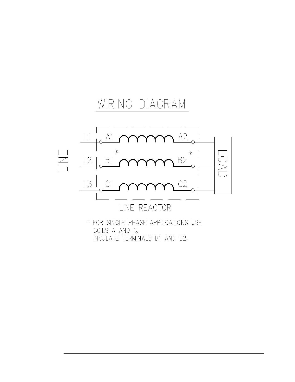
COMPONENT PACKAGE OPTION (CP)
52
Field Wiring In format ion
Below is the typical wiring diagram for the 3-phase reactor applied to the front end of the Variable
Frequency D rive (VFD). Si ngle-phase applications are acceptable, however, it is important to size the unit
based on the single pha se Full Load Amperage of the VFD. The input and output connections should be on
terminals A and C to ensure proper performance.
COMPONENT PACKAGE OPTION HG7 I, O, & M Manual
Page 55

Page 56

TCI, LLC
W132 N10611 Grant Drive
Germantown, Wisconsin 53022
Phone: 800-824-8282
Fax: 414-357-4484
Web Site: http://www.transcoil.com
©2014 TCI, LLC Publication No: 25165 Effective: 05/17/2014 Version: 2.6
Printed in USA
 Loading...