

Page 1
TRIPLE•C
MULTI-BAND COMPRESSOR & ENVELOPE
SINGLE CHANNEL/STEREO CHANNEL VERSION
USER’S MANUAL
Page 2

Page 3

3
TABLE OF CONTENTS
INTRODUCTION
Table of Contents . . . . . . . . . . . . . . . . .3
Introduction . . . . . . . . . . . . . . . . . . . . . .5
Front Panel . . . . . . . . . . . . . . . . . . . . . .6
Rear Panel . . . . . . . . . . . . . . . . . . . . . .8
Signal Flow Diagram . . . . . . . . . . . . . . .9
TRIPLE•C Setups . . . . . . . . . . . . . . . .10
BASIC OPERATION
The TRIPLE•C Display . . . . . . . . . . . . .12
I/O Setup . . . . . . . . . . . . . . . . . . . . . .13
Recall . . . . . . . . . . . . . . . . . . . . . . . . .15
Edit . . . . . . . . . . . . . . . . . . . . . . . . . . .15
Store . . . . . . . . . . . . . . . . . . . . . . . . . .15
COMPRESSION MODES
Full-range Mode . . . . . . . . . . . . . . . . .16
Multi-band Mode . . . . . . . . . . . . . . . . .18
Envelope Mode . . . . . . . . . . . . . . . . . .20
Sidechain Operation . . . . . . . . . . . . . .22
Using Compression - A Guide . . . . . . .23
APPENDIX
Important Safety Instructions . . . . . . . .26
MIDI Implementation . . . . . . . . . . . . . .28
MIDI Control Changes . . . . . . . . . . . . .29
Technical Specifications . . . . . . . . . . .30
Preset List . . . . . . . . . . . . . . . . . . . . . .31
TC Electronic, Sindalsvej 34, DK-8240 Risskov - tcdk@tcelectronic.com English version Rev 1.02 - SW - V 1.01
Prod. No: E60500421
Page 4

Page 5
5
INTRODUCTION
Congratulations on the purchase of your new TC Electronic TRIPLE•C Compressor
The TRIPLE•C is a highly flexible Compressor especially designed for single source processing but with a great
variety of applications. Whether your main tasks are live production or in the recording studios we are confident the
TRIPLE•C will cover your needs when it comes to compression. Three compression modes will comply the
flexibility needed when working with different program material such as vocals, drums, bass, guitar etc.
• The Multi-band mode allows compression and spectral balancing of three independent bands on any single
source without getting into the usual problems of pumping and breathing.
• The Full-range mode, offers standard compression utilizing the feed forward principle known from
various analog Compressors. The TRIPLE•C simulates the best from analog Compressors and provides
top quality Full-band compression instantaneously.
• The Envelope mode allows changing the dynamic content of the incoming source material in its entire
duration. This can be used for various kinds of dynamic shaping e.g. for extending the sustain source or
adding more “click” to percussive material such as a bass drum. The Envelope mode will also apply
in many Dance/DJ and more experimental types of music as a powerful tool of expression.
• The Sidechain function allows an external source to either fully control or contribute to the control of the
compression performed by the TRIPLE•C.
• The TRIPLE•C Stereo version can perform either as a two stereo Compressor or as a TRIPLE•C Single
version with Sidechain option.
Additionally the TRIPLE•C features all the best from the digital world such as factory and user presets,
remote controllability via MIDI and Digital I/O.
This manual covers both the TRIPLE•C Single Channel version as well as the TRIPLE•C Stereo Channel version.
Page 6
6
FRONT PANEL
POWER key
On/Off switch for the unit.
INPUT LEVEL knob
Adjusts the Input level.
Range is -6dB to +18dB.
INPUT/OUTPUT meters
Peak meter showing Input and
Output level. The meter range is:
0, -3, -6 ,-12, -18, -24, -40dB.
For the Stereo version this meter
is common for both channels.
INPUT OVERLOAD LED
The OVERLOAD LED indicates
one of two situations: The Input
level is too hot and therefore overloading or there is an internal DSP
overflow. The OVERLOAD LED is
lit when 1 sample is @ 0dBFS.
OUTPUT OVERLOAD LED
Indicates that the Output is too
hot. This will occur if e.g. too
much gain has been added
through the TRIPLE•C.
The OVERLOAD LED is lit when
1 sample is @ 0dBFS.
INPUT - Analog/Digital
Indicates whether the TRIPLE•C is
set to analog or digital Input.
When set to digital Input, the
Sample Rate automatically
switches to DI. In case of no or
unacceptable clock the "Digital"
and "DI" icon will be blinking.
SYNC
Indicates the current clock of
the TRIPLE•C. When locked to
an external clock, the "DI" icon
is lit and the incoming Sample
Rate is displayed by either the
44.1 or 48 icon.
If no or unacceptable clock is
available, the "Digital" and "DI"
icons will be blinking.
LINK indicator
Indicates that the unit is linked
to a second TRIPLE•C.
MIDI
When MIDI information is
received the MIDI icon will
blink.
Gain Metering
The Gain meter indicates the
total gain through the TRIPLE•C
and simultaneously shows the
gain reduction.
Envelope Section
Indicates the setting of the
Envelope Mode. Please see
Envelope chapter in the
manual for further information.
TRIG
Indicates when the Envelope
function is processing the
incoming signal.
LIMIT
When the LIMIT LED is lit the
Envelope Softclipper is active.
MULTI-BAND OFF key
Turns the Multi-band mode
on/off i.e. activates the full
band mode. When the LED is lit
the Multi-band algo is inactive.
PEAK SENSITIVE key
The TRIPLE•C is basically an
RMS based Compressor, meaning that it responds to average
level of the incoming source
material. This key turns the
TRIPLE•C into a Peak based
Compressor. When the LED is
lit the TRIPLE•C is in Peak
mode. This feature is only
available in Multi-band mode.
SOFTLIM key
Activates/deactivates the SoftLimiter in the Output section
When the LED is lit, the SoftLimiter is active.
Page 7
7
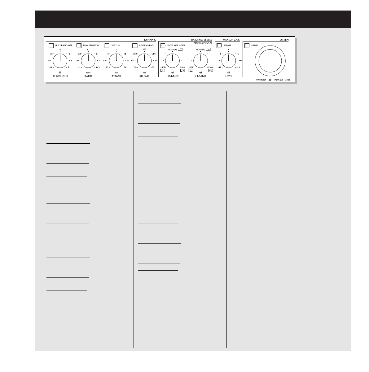
FRONT PANEL
LOOK AHEAD key
When in Multi-band mode the
Look Ahead delay (3ms) can be
activated allowing even more precise processing.
THRESHOLD knob
Multi-band mode:
Sets the Mid
band Threshold value. The Lo/Hi
bands are slaved accordingly.
Full-range mode:
Sets the
Threshold value.
Envelope mode: Sets the
Threshold of the Envelope.
RATIO knob
Multi-band mode:
Sets the Mid
band Ratio value. The Lo/Hi
bands are slaved accordingly.
Full-range mode:
Sets the
compression Ratio.
Envelope mode:
No function.
ATTACK knob
Multi-band mode: Sets the Mid
band Attack value. The Lo/Hi
bands are slaved accordingly.
Full-range mode:
Sets the Attack
time.
Envelope mode:
Sets the Attack
time of the gain added to the
start-up of the source.
BYPASS key
Bypasses all processing parameters
but not the System settings found in
the I/O menu. When the key LED is
lit the TRIPLE•C is bypassed.
LEVEL knob
Sets the overall Make Up gain
through the TRIPLE•C. This is used
to compensate for gain loss in the
Compressor. The absolute gain
through the TRIPLE•C is displayed
in the LCD by the fixed LED in the
gain meter. Range: +/- 18dB.
MENU key
Push MENU and use the VALUE
SET wheel to select menu.
PARAMETER wheel
Scrolls between parameters.
VALUE SET/ENTER wheel
Is used to change values.
When pushed, actions such as
Recall, Store etc. are approved.
RELEASE knob
Multi-band mode:
Sets the Mid
band Release time. The Lo/Hi
bands are slaved accordingly.
Full-range mode:
Sets the
Release time.
Envelope mode:
Sets the
Release time of the gain added to
the ring-out of the source.
ENVELOPE MODE key
Activates/deactivates the
Envelope mode.
LO-BAND knob
Multi-band mode:
Adjusts the Output level of the
processed Lo-Frequency band.
Full-range mode:
No function
Envelope mode: Attack Gain.
HI-BAND knob
Multi-band mode:
Adjusts the Output level of the
processed Hi-Frequency band.
Full-range mode:
No function
Envelope mode: Release Gain.
Page 8
8
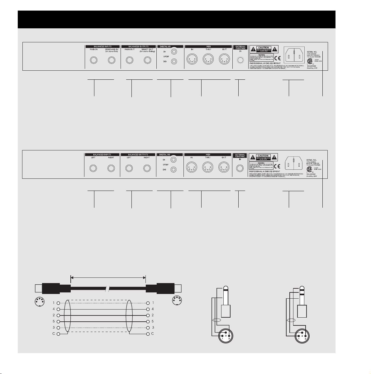
REAR PANEL
Balanced
Jack
Analog
Inputs
Balanced
Jack
Analog
Outputs
Pedal Input
for Bypass
MIDI
In, Out, Thru
Digital
S/PDIF
Input/
Output
Sleeve - Pin 1 (Ground)
Tip - Pin 2 (Hot)
Ring - Pin 3 (Cold)
Sleeve - Pin 1 (Ground)
Tip - Pin 2 (Hot)
Sleeve - Pin 3 (Cold)
Jack (unbalanced) - XLR
Jack (balanced) - XLR
TIP
RING
GND
TIP
GND
MIDI Cable
DIN CONNECTOR
5POLE - MALE
45 degrees
DIN CONNECTOR
5POLE - MALE
45 degrees
max. 10m
SHIELDED CABLE (3 or 5 wires + screen)
Serial no.Power
Input
Balanced
Jack
Analog
Inputs
Balanced
Jack
Analog
Outputs
Pedal Input
for Bypass
MIDI
In, Out, Thru
Digital
S/PDIF
Input/
Output
Serial no.Power
Input
Single Version
Stereo Version
Page 9
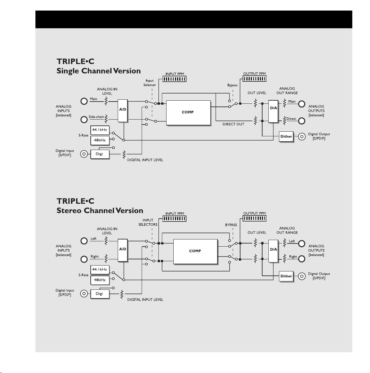
9
SIGNAL FLOW
Page 10
10
TRIPLE•C - SETUPS
Setting up the TRIPLE•C
The TRIPLE•C is a very flexible unit and may be used in numerous different setups. Here are illustrations
and explanations of some of the most common setups.
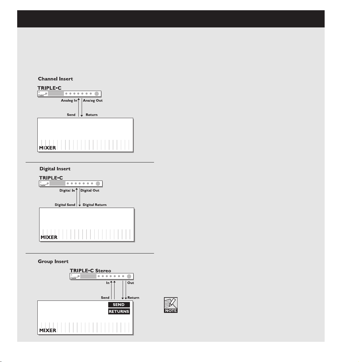
TRIPLE•C in a Single Channel Insert
• Use the send/return connections on a single channel
on your analog mixer.
• Use the analog Input/Outputs on the TRIPLE•C.
• Set the TRIPLE•C Inputs to analog.
TRIPLE•C Stereo version in a Group Insert
• Connect the TRIPLE•C Stereo in a group-insert on your
mixer.
• With this setup you are able to use compression on e.g.
an entire drum-set or on backing vocals.
Please note that if you route one or more channels
on your mixer to both the Master Out and to a
subgroup where a digital Compressor is inserted, you
can experience an unwanted comb-filtering effect.
TRIPLE•C in a Digital Insert
• Connect the TRIPLE•C’s digital In/Out to a digital
Send/Return on your mixer.
• Use the TRIPLE•C as master clock by setting the
Clock parameter in the I/O menu to 44.1kHz or 48kHz
and the connected device/mixer to External.
Page 11

11
TRIPLE•C - SETUPS
Setting up the TRIPLE•C
EQ Insert in the TRIPLE•C Sidechain
• Connect the TRIPLE•C Direct Out to the Input of the
EQ and the EQ Output to the TRIPLE•C Input.
• Set Sidechain to “On”.
• The source signal passing the TRIPLE•C will not be
directly influenced by the connected EQ unit, however
the EQ will allow you to pinpoint the key frequencies
that you want the Compressor to respond to.
Side Chain “On”
• Use the send/return connections on a single channel
on your mixer.
• Connect the Output of the channel you wish to
contribute to(Add) or control(On) the compression.
• Press MENU, select Ext Side using the PARAMETER
wheel and select “Add” or “On” using the VALUE SET
wheel.
In the illustrated example the Bass drum channel will
either contribute to, or control the compression applied
on the Bass channel.
Stereo Setup Using two TRIPLE•C Single Channels
• Connect two TRIPLE•C Single Channel units as illustrated.
• On both units:
Press MENU, select “I/O Menu” using the VALUE SET
wheel. Press ENTER, select “Link” using the
PARAMETER wheel and set the Link parameter to “On.”
• Connect MIDI Out from the unit you wish to be “master”
to MIDI In on unit you want to operate as “slave”.
• The units now operate as one stereo unit.
All parameter adjustments performed on the “master”
are now instantaneously copied to the “slave” unit.
Page 12

12
THE TRIPLE•C DISPLAY
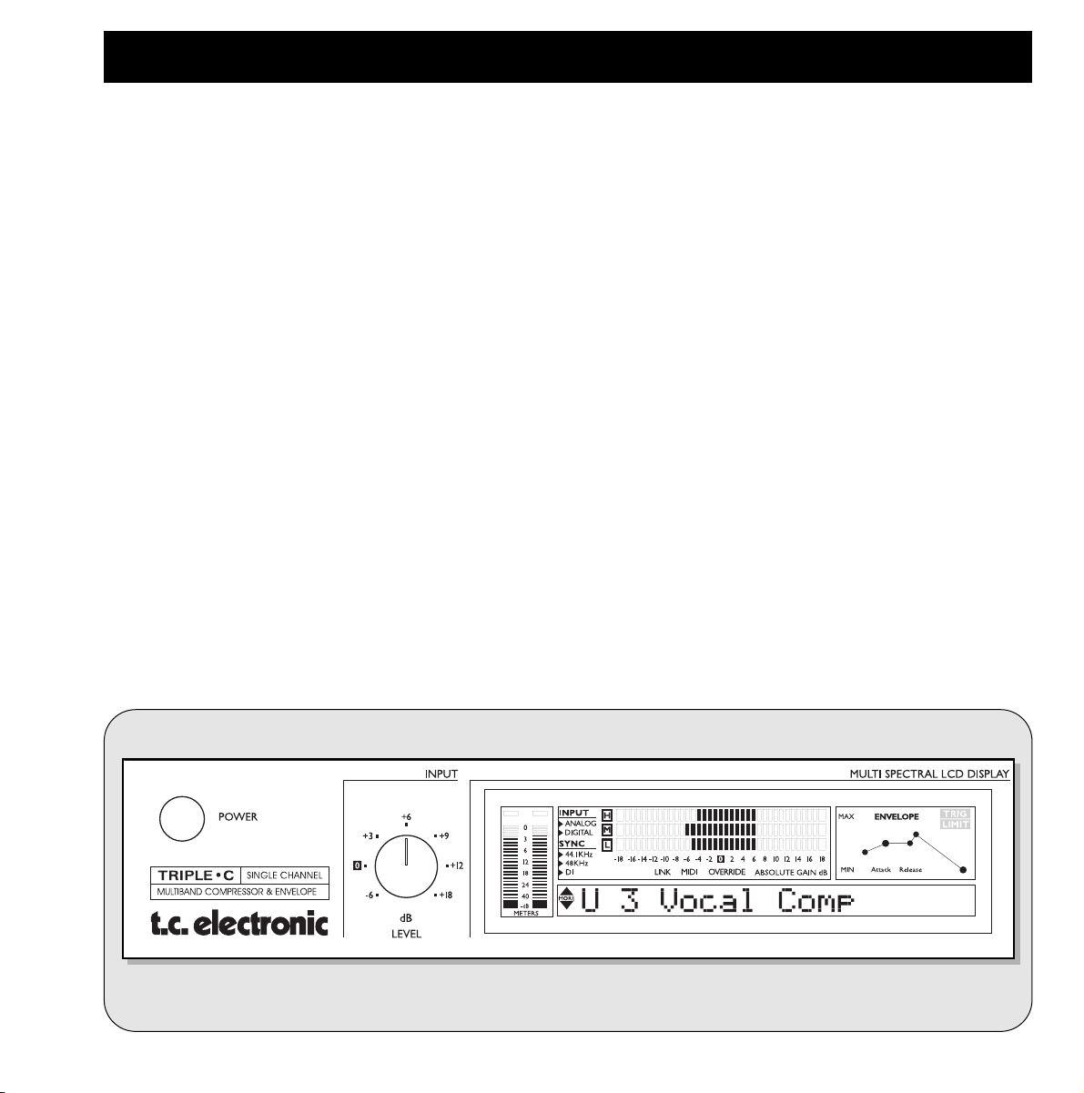
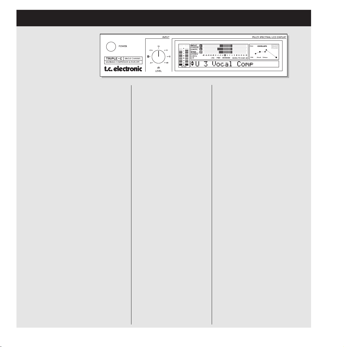
Input Meter Output Meter
Overload LEDs Input Type
Indicator
Sync
Indicator
Gain
Metering
Envelope
Processing
Limiter
Indicator
Envelope
Setting
Link Mode
MIDI
Override
Absolute Gain
Alpha/Numeric DisplayCurrent Clock Status
Input/Output meters
Peak meter showing Input and Output level. The Meter
range is: 0, -3, -6 ,-12, -18, -24, -40dB.
Input Overload LED
The OVERLOAD LED indicates one of two situations: The
Input level is too hot and therefore overloading or there is
an internal DSP overflow. The Overload LED is lit when
1 sample is @ 0dBFS.
Output Overload LED
Indicates when the Output is too hot. This will occur if e.g.
too much gain has been added through the TRIPLE•C.
The Overload LED is lit when 1 sample is @ 0dBFS.
Input - Analog/Digital
Indicates whether the TRIPLE•C is set to analog or digital
Input. When set to digital Input, the Sample Rate automatically switches to DI. In case of no or unacceptable clock
the "Digital" and "DI" icon will be blinking.
Sync
Indicates the current clock of the TRIPLE•C. When locked
to an external clock, the "DI" icon is lit and the incoming
Sample Rate is displayed by either the 44.1 or 48 icon.
If no or unacceptable clock is available, the "Digital" and
"DI" icons will be blinking.
Link indicator
Indicates that the unit is linked to a second TRIPLE•C.
MIDI
When MIDI information is received the MIDI icon will blink.
Gain Metering
The Gain meter indicates the total gain through the
TRIPLE•C and simultaneously shows the applied gain
reduction.
Envelope Setting
Indicates the setting of the Envelope Mode. Please see
Envelope chapter for further information.
Trig
Indicates when the Envelope function is processing the
incoming signal.
Limit
When the LIMIT LED is lit the Softclipper is active.
Override
When recalling a preset it is most likely that eg. Threshold,
Ratio, Attack and Release settings do not match the
positions of the corresponding knobs on the front. When
turning one of these knobs the current value is displayed in
the display and the OVERRIDE LED will blink until you
pass the “knob-position” that matches the actual parameter
setting. When this “match-point” is passed the parameter
can be adjusted.
Page 13

13
I/O SETUP
Please note that when using internal clock with
external digital audio, the incoming digital audio
must be in sync with the TRIPLE•C internal clock in
order to avoid slip-samples.
"***Rate Mismatch****"
This Error message will occur in the display if the TRIPLE•C
detects slip-samples. Typically this problem only occurs in
special clock setups e.g. if the TRIPLE•C is running via
internal clock, while processing audio from the Digital Input.
If the incoming clock and the internal clock does not match
the TRIPLE•C will display the above written error message.
Out Range
Range: 2dBu, 8dBu, 14dBu and 20dBu.
Sets the maximum gain range of the analog Output stage.
Analog Out Level
Adjusts the analog Output level. Range: 0 to -100dB
Digital In Gain
Adjusts the Digital In level. This parameter is only active
when Digital In is selected.
Dither
Going from one type of bit resolution to a lower, e.g. from
24 bit to 16 bit, you actually loose 8 bits of information.
The process of cutting off bits is called truncation and it
introduces digital distortion of low level signals, due to the
lack of complete signal information. To compensate for this,
dither must be applied. Dither is a small amount of filtered
noise that generates randomization at the noise floor,
thereby ensuring a less distorted low level signal.
Dithering is relevant only on digital Outputs and it is always
the receiving device that determines the number of bits you
must dither to. A CDR or a DAT recorder should normally
be dithered to 16 bit.
Status Bits
Sets whether the TRIPLE•C is sending out AES/EBU
(professional standard) or S/PDIF (consumer standard)
status bits.
MIDI Channel
Range: Off/1-16/Omni.
Sets the responding MIDI channel of the TRIPLE•C.
I/O Setup
In the I/O menu you will find all system related parameters
such as Input/Output settings, analog/digital, Status Bit,
Dither and various MIDI settings. For successful operation
of the TRIPLE•C these parameters must be correctly set !
To access the I/O menu
• Press MENU.
• Select I/O Menu using the VALUE SET wheel.
• Press ENTER to enter I/O Menu.
In the I/O Menu you select parameters using the
PARAMETER wheel and you change values using the
VALUE SET wheel.
Input
Select between Analog or Digital.
Analog Input
When "Analog" is selected the TRIPLE•C automatically
defaults to the internal 44.1kHz clock as Sample Rate.
Digital Input
When "Digital" is selected the TRIPLE•C attempts to lock to
the S/PDIF Input. During the lock-up period the "DI" display
icon blinks indicating none or unacceptable clock, and the
Outputs are muted. When lock is achieved the "DI" icon
turns solid, and the Outputs are un-muted.
Clock
Analog Input
When Input source is analog the following Sample Rates
are available:
Internal 44.1kHz - The TRIPLE•C runs at internal 44.1kHz.
Internal 48kHz - The TRIPLE•C runs at internal 48kHz.
Digital - The TRIPLE•C locks to the incoming digital clock.
Digital Input
When Input Source is digital the following Sample Rates
are available:
Internal 44.1kHz - The TRIPLE•C runs at internal 44.1kHz.
Internal 48kHz - The TRIPLE•C runs at internal 48kHz.
Digital - The TRIPLE•C locks to the incoming digital clock.
Page 14

14
MIDI CC
Range: On/Off.
Determines whether the TRIPLE•C should respond to MIDI
Continuous Controllers or not. On page 29 you will find a
list of the TRIPLE•C Continuous Controllers.
Program bank
Determines which bank an external MIDI device will
address in the TRIPLE•C when sending a program change.
The options are: Factory, User or External.
When External is selected controller #32 can be used to
address either the Factory or the User bank.
Factory bank: Controller #32=0
User bank: Controller #32=1
Bulk Dump
Press ENTER to perform a total Bulk dump of all presets to
an external MIDI device such as a MIDI sequencer.
The TRIPLE•C is always ready to receive MIDI Bulk dump
information.
SysEx ID
Determines the Sys-Ex ID number of the unit. All effects
parameters; algo changes and routings can be changed
through MIDI Sys-Ex via an external MIDI device. In order
to define which unit the sent MIDI Sys-Ex information
should reach, the appropriate ID number must be set.
Link
Range:On/Off
Will link parameters between two Single Channel units
when connected and used either in a Stereo Setup or in a
Dual Mono setup.
Please see page 22 for further explanation.
View Angle
Adjusts the LCD display backlight for better viewing
comfort.
I/O SETUP
Page 15

15
RECALL - EDIT - STORE
Presets in general
The TRIPLE•C holds 50 factory presets (ROM bank) and
you are able store 100 additional user presets in the RAM
bank. When scrolling through the presets you will locate
the user presets after the 50 factory presets.
Recall
To recall a preset:
• Press MENU.
• Dial the VALUE SET wheel until the display reads
“Recall”.
• Press ENTER.
• Use any wheel to scroll through the 50 Factory and 100
User presets. Until you have actually recalled a preset
you are previewing. While previewing the preset name
and number is blinking.
• Press ENTER to recall a preset.
The TRIPLE•C prompts "Recalled" for approximately
one second and returns preset-name display.
Edit
To edit preset parameters:
• Press MENU.
• Select “Edit Menu” using the VALUE SET wheel.
• Press ENTER.
• Select parameter using the PARAMETER wheel and
change values using the VALUE wheel.
Store
To store a preset with the same name:
• Press MENU.
• Turn the VALUE SET wheel until the display reads
“Store”.
• Press ENTER.
• The TRIPLE•C suggests the first available RAM space
as storing location but you can select any of the 100
locations using the VALUE SET wheel.
• Press ENTER twice to store.
To rename a preset while storing:
• Press MENU.
• Dial the VALUE SET wheel to until the display reads
“Store”.
• Press ENTER.
• Select storing space using the VALUE SET wheel.
• For altering the preset name; use the PARAMETER
wheel to move cursor and the VALUE SET wheel to
select character.
• Press ENTER twice to store the preset with the new
name.
Page 16

16
FULL-RANGE MODE
Full-range mode is the mode typically found in standard
Compressors. Threshold, Ratio, Attack and Release
settings apply for the entire frequency area.
To select the Full-range Mode
• ENVELOPE MODE key LED must be off/unlit.
• MULTI-BAND OFF LED must be lit.
Input Section
Input Level
Adjusts the Input level of the TRIPLE•C. Play your source
material through the TRIPLE•C and observe the Input
meters in the display. Correct operation level is approx -6
to -3dBs with an occasional peak at 0dB. If the Input signal
at any time overloads, - reduce the Input level.
Dynamic Section
Threshold
When the signal is above the set Threshold point the
Compressor is activated and the gain of any signal above
the Threshold point is processed according to the Ratio,
Attack and Release settings.
Ratio
The Ratio setting determines how hard the signal is
compressed. (see illustration above).
Example:
With a Ratio setting of 2:1 an Input signal at 4dB
above Threshold is reduced to only 2dB on the Output-side.
Attack
The Attack time is the response time of the Compressor.
The shorter Attack time the sooner the Compressor will
reach the specified Ratio after the signal rises above the
Threshold point.
Release
The Release time is the time it takes for the Compressor to
release the gain reduction of the signal after the signal
drops below the Threshold point again.
Softlim
Softlimiter on/off switch. Where the Compressor mostly is
used to gradually reduce the dynamic content above the
set Threshold point a limiter is used to directly avoid hitting
the upper limit of 0dBFS. Compressors and limiters are
often used in conjunction. - The Compressor as the musical/gentle way of reducing the level and the limiter as a
hard abrupt control to avoid distortion. See illustration.
In Full-range mode the controls in the Spectral
adjust section have no effect.
Look Ahead
The Look Ahead delay function is not available in the
Full-range mode
Makeup Gain Section
Bypass
Press to bypass the TRIPLE•C. All processing parameters
are bypassed. Input Level control and all System settings
found in the I/O menu are not bypassed.
Level
When a signal is compressed, the maximum Output level
of the signal is reduced. Since it is a reduction in dynamic
content and not a gain-reduction that is the object of
applying compression a make-up gain is necessary to lift
the signal to appropriate level. Observe the gain reduction
via the meters and lift the processed signal to approximately
0dB using the Level knob in the Make Up Gain section.
For detailed information please read the section on make
up gain in the section called “Using Compression”.
Page 17
17
FULL-RANGE MODE
Edit Menu
To enter the Edit menu
• Press MENU.
• Use the VALUE SET wheel to select the Edit menu
and press ENTER.
DRG - Digital Radiance Generator
Range: 1-10
With this parameter you can add second harmonic
distortion. This is a commonly used tube-simulation that will
add warmth to the signal.
External Sidechain
Range: Off, On, Add
Determines how the TRIPLE•C should respond to the
signal present on the External Sidechain.
Off : This is the ”Normal” setting. The TRIPLE•C will
only respond to the Input signal and not to any
signal present on the Sidechain.
On : The compression will be controlled only by the
signal present on the Sidechain Input.
Add : In this mode the TRIPLE•C will respond both to
the Input signal and to the signal present on the
Sidechain. The Input signal and the Sidechain
signal are added for compression control.
Please note that the signal present on the
Sidechain Input under no circumstances is
passed to the Outputs. The Sidechain Input is
only for compression control.
Hi X-Over, Lo X-Over and Comp Style parameters
are ineffective in the Full Range mode.
Page 18

18
MULTI-BAND MODE
Multi-band mode - is a 3 band compression mode. By
dividing the source material into 3 frequency areas you can
avoid that peaks at certain frequencies controls the
compression of the entire signal. By setting the Lo and Hi
Cross-over frequencies you determine the range of the
Frequency areas.
To select Multi-band mode
• ENVELOPE MODE key LED must be off/unlit.
• MULTI-BAND OFF LED must be unlit.
Input Section
Input Level
Adjusts the Input level of the TRIPLE•C. Play your source
material through the TRIPLE•C and observe the Input
meters in the display. Correct operation level is approx
-6 to -3dB with an occasional peak at 0dB. If the the Input
signal at any time overloads - reduce the Input level.
Dynamic Section
Threshold
When the signal is above the set Threshold point the
Compressor is activated and the gain of any signal above
the Threshold point is processed according to the Ratio,
Attack and Release settings.
Ratio
The Ratio setting determines how hard the signal is
compressed. (see illustration above).
Attack
The Attack time is the response time of the Compressor.
The shorter Attack time the sooner the Compressor will
reach the specified Ratio after the signal rises above the
Threshold point.
Release
The Release time is the time it takes for the Compressor to
release the gain reduction of the signal after the signal
drops below the Threshold point again.
Peak Type
The TRIPLE•C is basically an RMS based Compressor,
meaning that it responds to the average level of the incoming source material. This key turns the TRIPLE•C into a
Peak based Compressor. When the key LED is lit the
TRIPLE•C is in Peak mode. Peak mode is the general
choice when processing percussive material. This feature is
only available in Multi-band mode.
Softlim
Softlimiter on/off switch. Where the Compressor mostly is
used to gradually reduce the dynamic content above the
set Threshold point a limiter is used to directly avoid hitting
an upper limit. Compressors and limiters are often used in
conjunction. - The Compressor as the musical/gentle way
of reducing the level and the limiter as a hard abrupt control to avoid distortion. See illustration.
Look Ahead
Press to activate the 3ms Look-ahead delay. This gives an
even better and more precise compression performance of
the TRIPLE•C. - 3ms is approx the time it takes for sound
to travel 1 meter.
Spectral Adjust
Lo-Freq & Hi-Freq Controls
Applying the same Ratio, Attack and Release settings for
both Lo, Mid and Hi bands will often result in an un-even
Output frequency balance. With the Lo-Freq and Hi-Freq
controls you can adjust the Output level of the Lo and
Hi-Frequency bands.
Page 19

19
MULTI-BAND MODE
Makeup Gain
Bypass
Press to bypass the TRIPLE•C. All processing parameters
are bypassed. Input level control and all system settings
found in the I/O menu are not bypassed.
Level
When a signal is compressed the max Output level of the
signal is reduced. Since it is a reduction in dynamic
content and not a gain-reduction that is the object of
applying compression a make-up gain is necessary to lift
the signal to appropriate level. Observe the gain reduction
via the meters and lift the processed signal to approx. 0dB
using the Level knob in the Make Up Gain section.
For detailed information please read the section on make
up gain in the section called “Using Compression”.
Edit Menu
To enter the Edit menu.
• Press MENU.
• Use the VALUE SET wheel to select the Edit menu
and press ENTER.
Comp Style
Various predefined Compression Styles can be selected.
Evaluate the Source material and choose appropriate style.
DRG - Digital Radiance Generator
Range: 0 -10
With this parameter you can add second harmonic
distortion. This is a commonly used tube-simulation that will
add warmth to the signal.
Hi X-Over
Range: 20Hz to 20kHz
Sets the Hi Frequency Cross-over point.
Lo X-Over
Range: 20Hz to 20kHz
Sets the Lo Frequency Cross-over point.
External Sidechain
Range: Off, On, Add
Determines how the TRIPLE•C should respond to the
signal present on the External Sidechain.
Off : This is the ”Normal” setting. The TRIPLE•C will
only respond to the Input signal and not to any
signal present on the Sidechain.
On : The compression will be controlled only by the
signal present on the Sidechain Input.
Add : In this mode the TRIPLE•C will respond both to
the Input signal and to the signal present on the
Sidechain. The Input signal and the Sidechain
signal are added for compression control.
Please note that the signal present on the
Sidechain Input under no circumstances is
passed to the Outputs. The Sidechain Input is
only for compression control.
Meters
In Multi-band mode the meters indicates the applied
compression in both the Lo, Mid, and Hi bands.
Cross-over Freq - illustration.
Page 20

20
ENVELOPE MODE
To select the Envelope mode
• Press the ENVELOPE MODE key in the Spectral Adjust
section.
Input Section
Input Level
Adjusts the Input level of the TRIPLE•C. Play your source
material through the TRIPLE•C and observe the Input
meters in the display. Correct operation level is approx -6
to -3dBs with an occasional peak at 0dB. If the the Input
signal at any time overloads, - reduce the Input level.
Dynamic Section
Threshold (1)
When the signal is above the set Threshold point the
Compressor is activated and the gain of any signal above
the Threshold point is processed according to the Attack
and Release settings.
Envelope Attack Gain (2)
This is the level the signal will be boosted/attenuated to in
0.1ms (fixed response time) when the signal exceeds the
Threshold.
Attack (3)
The Attack time is the time it takes for the Compressor to
reach Threshold level again.
Sustain Period (4)
This is not an adjustable parameter. The signal is sustained
at the Threshold level until the Input signal drops below the
Threshold point (5).
Release (6)
The Release time Defines the time the Compressor
continues to process the signal after the Input signal has
dropped below Threshold.
Envelope Release Gain
This is the gain applied to the signal after the signal has
dropped below the Threshold point. This can be used e.g.
to manipulate the sustain of the signal.
Peak Type
Peak Type is not available in the Envelope mode.
Envelope mode is a special feature of the TRIPLE•C that lets you control the entire compression process in detail allowing full
control from the point where the Compressor starts modifying the signal until it releases its grip again.
Page 21

21
ENVELOPE MODE
Softlim
Softlimiter on/off switch. Where a Compressor mostly is
used to gradually reduce the dynamic content above the
set Threshold point a limiter is used to directly avoid hitting
an upper limit. Compressors and limiters are often used in
conjunction. - The Compressor as the musical/gentle way
of reducing the level and the Limiter as a hard abrupt
control to avoid distortion. See illustration.
Makeup Gain
Bypass
Press to bypass the TRIPLE•C. All processing parameters
are bypassed. Input Level control and all System settings
found in the I/O menu are not bypassed.
Level
When a signal is compressed the max Output level of the
signal is reduced. Since it is a reduction in dynamic
content and not a gain-reduction that is the object of
applying compression a make-up gain is necessary to lift
the signal to appropriate level. Observe the gain reduction
via the meters and lift the processed signal to approx. 0dB
using the Level knob in the Make Up Gain section.
For detailed information please read the section on make
up gain in the section called “Using Compression”.
Edit Menu
To enter the Edit menu
• Press MENU.
• Use the VALUE SET wheel to select the Edit menu
and press ENTER.
DRG - Digital Radiance Generator
Range: 1-10
With this parameter you can add second harmonic
distortion. This is a commonly used tube-simulation that will
add warmth to the signal.
External Sidechain
Range: Off, On, Add
Determines whether the TRIPLE•C should respond to the
signal present on the External Sidechain.
Off : This is the ”Normal” setting. The TRIPLE•C will
only respond to the Input signal and not to any
signal present on the Sidechain.
On : The compression will be controlled only by the
signal present on the Sidechain Input.
Add : In this mode the TRIPLE•C will respond both to
the Input signal and to the signal present on the
Sidechain. The Input signal and the Sidechain
signal are added for compression control.
Please note that the signal present on the
Sidechain Input under no circumstances is
passed to the Outputs. The Sidechain Input is
only for compression control.
Hi X-Over, Lo X-Over and Comp Style are
ineffective in the Envelope mode.
Page 22

The TRIPLE•C can be set up to use an external source as
Sidechain Input to either control or contribute to the
compression of the source material. The Sidechain modes
allows the TRIPLE•C to react on either:
• The Sidechain Input only. (ON - mode)
• A mix between the original Input and the Input present
on the Sidechain. (ADD - mode)
T
o select the Sidechain mode:
• Press MENU.
• Select the “Edit menu” using the VALUE SET wheel and
press ENTER.
• Use the PARAMETER wheel to select “Ext Side” and the
VALUE SET wheel to select Sidechain mode.
Ext. Sidechain set to “ON”
Over-writes the original source and takes full control of the
responds of the Compressor. This can be used in various
applications e.g. for inputting a spectrally shaped version of
the original source, and thereby force the Compressor to
respond to a certain frequency area.
Ext. Sidechain set to “ADD”
Mixes the signal present on the external Sidechain In with
the original source material present on the Main Input.
22
SIDECHAIN OPERATION
Stereo Link
Stereo Setup
It is possible to use two TRIPLE•C Single Channel units as
one stereo compressor where all parameters are linked.
T
o acheive this:
• Connect Direct Out of the “Master” TRIPLE•C to the
Sidechain In of the “Slave” TRIPLE•C and vice versa
(see illustration below).
• Connect MIDI Out from the “Master” to MIDI In on the
“Slave”.
• Go to the I/O menu on both units and select Link “On”.
The “Master” TRIPLE•C is now controlling all parameters of
the “Slave” TRIPLE•C. With this setup the two units will
operate as one stereo Compressor. Both units/channels
will respond and compress the source material according
to the signal present on both Input channels.
Dual Mono Setup
To use two TRIPLE•C units in a dual-mono setup, no
Sidechain connections should be made - only MIDI Out
from the “Master” unit to MIDI In on the “Slave” unit.
Select Link “On” in the I/O menu on both units and all
parameters on the “Master” unit are now automatically
copied to the “Slave” unit. The two units will respond only
to their own Input.
External EQ
TRIPLE•C Stereo Channel
When using the TRIPLE•C Stereo Channel version as a
Single Channel Compressor with Sidechain use:
• Left Input and left Output for source material processing.
• Right Input for Sidechain Input.
• Right Output for Direct Out.
Page 23

23
USING COMPRESSION - INTRODUCTION
Compression in general
If you are an experienced user of audio Compressors you
may want to skip this section, which is a general
explanation of what Compressors do and how they are
applied in audio production.
Compression is generally used to reduce the dynamic
content of an audio signal. Now, why is this necessary?
Compared to the human ear any electronic reproduction of
audio is limited by the available technology. Whereas the
human ear has an incredible flexibility/dynamic range, letting you hear a pin dropping one moment, and an airplane
taking off the moment after, - various physical limitations of
the electronic components makes this type of flexibility
impossible to achieve in audio reproduction.
Electronic reproduction of sound has two limitations. In the
low end, the signal level must be well above the base
noise, also referred to as the “noisefloor” introduced by the
electronic components. The upper limit is determined by
the internal operating voltages. If exceeded, distortion will
be the result. As a certain amount of headroom needs to
be reserved for peaks in the audio material even less
dynamic range is available. So, on one hand you would like
to have as much headroom as possible, but at the same
time avoid having the average level too close to the noise
floor. This is where compression is applied. With the
Compressor you control/reduce the peaks in the audio
signal and the average level of the audio signal can be
increased.
The first type of Compressors (in the 1930's) were very
simple constructions with two controllable parameters. With
one of the two controls the user had to find a setting based
upon an presumed average audio level of the material
about to be processed. The other control (Ratio) specified
the reduction of dynamic content in the entire signal that
passed through the unit. This way the signal was compressed from both sides, low levels were increased by the
same amount as the high levels were decreased.
Modern Compressors uses a Threshold point. When the
signal increases above the specified Threshold point the
Compressor begins to reduce the Output signal by an
amount set by the Ratio parameter. Once the signal drops
below the Threshold point the Compressor stops interfering.
Compressors vs Limiters
Where the Compressor mostly is is used to gradually
reduce the dynamic content above the set Threshold point
a limiter is used to directly avoid hitting an upper limit.
Compressors and limiters are often used in conjunction. The Compressor as the musical/gentle way of reducing the
level and the limiter as a hard abrupt control to avoid
distortion/clipping.
Multi-band Compression
With multi-band Compressors such as the TRIPLE•C you are
able to differentiate the compression on different frequency
areas in the audio signal. The audio signal is split in to
several frequency areas and you can obtain considerably
better results when working with a complex signal with a
wide frequency area. When working with an non-multi-band
Compressor on e.g. a bass drum will invoke the Compressor
to reduce the dynamic content of the entire signal when
activated. This gives what it often referred to as the "pumping/breathing" effect. By splitting up the signal in to e.g. 3
bands; low, mid and high and use different Threshold/Ratio
settings on these bands a much better result can be
achieved.
However, there are times to use multi-band compression
and times to use traditional full-range compression. The
TRIPLE•C gives you both.
Page 24

24
USING COMPRESSION
Though you can say that using a Compressor in general is
about reducing the dynamic content of a signal thereby
having better control, there are many different angles on
how to use compression. Depending on the specific
application you may have different starting points and goals
when you apply compression. As personal style also is a
major consideration it is hard to give specific answers on
how to use compression. However, here are some guidelines.
First a short description of the basic parameters.
Illustration
Dynamic Section
Threshold
When the signal rises above the set Threshold point the
Compressor is activated.
Ratio
The Ratio setting determines how hard the signal is
compressed.
Attack
The Attack time is the response time of the Compressor.
The shorter Attack time the sooner the Compressor will
start to work after the signal rises above the set Threshold.
Release
The Release time is the time it takes for the Compressor to
release the gain reduction of the signal after the signal
drops below the Threshold point again.
Example:
Threshold is set to -6dB
Ratio is set to 2:1
Attack is set to 10ms
Release is set to 300ms
A relatively loud musical phrase reaches -2dB on the Input.
As the Threshold is set to -6dB, 4dB of the signal will be
processed. The Ratio of 2:1 means that each of the 4dBs
above Threshold will be reduced to 0.5dB. So, the 4dB above
Threshold on the Input side will be reduced to only 2dB on
the Output. This gain-reduction is reached in 10ms which is
specified by the Attack time. When the Input signal drops
below the Threshold (-6dB) again, the Compressor ceases
to process/reduce the Output signal. The Release time
specifies how long it will take until no processing is taking
place.
Spectral Adjust Section
Selecting Full-range or Multi-band mode
Evaluate the frequency range of the source material. If your
source material has a wide frequency range with peaks in
specific frequency areas, the Multi-band mode should
probably be your choice. If on the other hand you are
working on e.g a repeating back-up vocal harmony within a
relatively small frequency area the Full range mode would
apply perfectly.
Better Definition of Vocal material
If the object is to define the Source material e.g a voice a
gentle compression would be appropriate. By delicately
controlling the peaks of the signal you are able increase
the overall level of the signal and the low level content of
the signal will be increased. Try using a high Threshold
setting to keep the dynamic content of the signal and to
avoid processing the entire signal all the time. A low to
medium Ratio and Attack setting will give you the soft and
often desired compression used when working with vocals.
Guideline Settings
Ratio: 2:1
Attack: 10ms
Release: 200ms
Page 25

25
USING COMPRESSION
The meters on the TRIPLE•C are excellent tools to achieve
this. Lets have a closer look at the meters.
When no signal passes through the unit the gain is
illustrated like this:
Try turning the Make-up Level knob to change the level.
If no compression is applied you are now actually changing
the Output level.
When the signal is processed/compressed the Output level
is reduced. The amount of gain reduction/compression
applied is illustrated via the via the meters like this:
(example in Multi-band mode)
To achieve the same Output level on the processed signal
as on the unprocessed signal simply turn up the Makeup
Gain level knob until the max gain reduction is at the 0dB
marker.
This will look approximately like this :
This is how easy it is to apply Make-up gain using the
TRIPLE•C.
Hard Compression of Vocal Tracks.
By compressing vocal source material hard a very distinct
and precise but less dynamic track will be the result. For
this purpose we need the Compressor to work practically
all the time. Therefore the Threshold must be set rather
low, the Ratio rather high and the Attack time short. The
release time setting again depends on what it is you would
like to achieve. If you with this “hard compression scenario”
wishes to hear e.g. the singer taking the next breath in
between his/hers actual singing a short Release time
should be your choice. A long release time on the other
hand would compensate for this
Guideline Settings
Ratio: 5-6:1
Attack: 5ms
Release: 100ms
Controlling Percussive Material
When using compression on e.g. a snare drum entirely
different aspects are to be taken in consideration compared
to vocal processing. A drum has a sharp attack but almost
no durance. For the Compressor to take effect at all a
really short Attack time is essential. The Threshold can be
set relatively low as you probably want to process all snaredrum hits. The Ratio setting for this application is really
where you can add different characteristics on the signal.
The higher a Ratio setting the more flat but distinct a sound
you can create. Too high a Ratio setting allows only a small
amount of the source materials original characteristics to
be maintained.
Guideline Settings
Ratio: 4:1
Attack: 1.0 ms
Release: 100ms
Makeup Gain
When a signal is compressed the max Output level of the
signal is reduced. Since it is a reduction in dynamic
content and not a gain-reduction that is the object of
applying compression a make-up gain is necessary to lift
the signal to appropriate level.
Also when using the bypass function for comparing the
unprocessed signal with the processed signal equal level
for these modes is essential.
Page 26

26
IMPORTANT SAFETY INSTRUCTIONS
Please read, keep, and follow these instructions before connecting this unit. Heed all warnings and instructions.
Retain this notice and the owner´s manual for future reference.
The lightning flash with an arrowhead symbol within an equilateral triangle, is intended to alert the user to the presence of
uninsulated “dangerous voltage” within the product’s enclosure that may be of sufficient magnitude to constitute a risk of
electric shock to persons.
The exclamation point within an equilateral triangle is intended to alert the user to the presence of important operating and
maintenance (servicing) instructions in the literature accompanying the product.
Warning!
• To reduce the risk of fire or electric shock, do not expose this unit to rain or moisture.
• Do not open the unit - risk of electric shock inside.
• This apparatus must be earthed.
• Use a three wire grounding type line chord like the one supplied with the product.
• Be advised that different operating voltages require the use of different types of line cord and attachment plugs.
If in doubt please contact your TC distributor.
• Check the voltage in your area and use the correct type. See table below:
• Mount in a well ventilated rack with a little space above and below.
• This equipment should be installed near the socket outlet and disconnection of the device should be easily accessible.
• Do not install near heat source, such as radiators, heat registers, stoves or other apparatus.
(including amplifiers) that produce heat.
• Do not rely solely on the front screws when mounted in touring rack. Support the back as well.
• Clean only with a damp cloth.
• Do not defeat the safety purpose of a polarized or grounding type plug. A polarized plug has two blades
with one wider than the other. A grounding type plug has two blades/prongs and a third grounding prong. The wide
blade or the third prong are provided for your safety. When the provided plug does not fit into your outlet,
consult an electrician for replacement of the obsolete outlet.
• Protect the power cord from being walked on or pinched particularly at plugs convenience receptacles, and the
point where they exit from the apparatus.
• Only use attachments/accessories specified by the manufacturer.
• Unplug this apparatus during lightning storms or when unused for long periods of time.
Voltage Line plug according to standard.
110-125V UL817 and CSA C22.2 no 42.
220-230V CEE 7 page VII, SR section 107-2-D1/IEC 83 page C4.
240V BS 1363 of 1984. Specification for 13A fused plugs and switched and un-switched socket outlets.
Page 27

27
IMPORTANT SAFETY INSTRUCTIONS
Service
There are no user-serviceable parts inside. All service must be performed by qualified personnel. Servicing is required when:
• the unit has been damaged in any way, such as when the power-supply cord or plug is damaged.
• the unit has been exposed to rain or moisture, or liquid has been spilled into the unit.
• objects have fallen into the unit.
• the unit does not work properly.
• the unit has been dropped.
For the customers in Canada:
This Class B Digital apparatus meets all requirements of
the Canadian Interference-Causing Equipment Regulations.
Cet appareil numérique de la classe B respecte toutes les
exigences du Réglement sur le matériel brouilleur du
Canada.
This equipment has been tested and found to comply with
the limits for a Class B Digital device, pursuant to part 15
of the FCC rules.
These limits are designed to provide reasonable protection
against harmful interference in a residential installations.
This equipment generates, uses and can radiate radio frequency energy and, if not installed and used in accordance
with the instructions, may cause harmful interference to
radio communications. However, there is no guarantee that
interference will not occur in a particular installation.
If this equipment does cause harmful interference to radio
or television reception, which can be determined by turning
the equipment off and on, the user is encouraged to try to
correct the interference by one or more of the following
measures:
• Reorient or relocate the receiving antenna.
• Increase the separation between the equipment and
receiver.
• Connect the equipment into an outlet on a circuit different
from that to which the receiver is connected.
• Consult the dealer or an experienced radio/TV technician
for help.
The user may find the following booklet, prepared by the
Federal Communications Commission, helpful:
"How to identify and Resolve Radio/TV interference
Problems."
This booklet is available from the US. Government Printing
Office, Washington, DC 20402, Stock No. 004-000-0034-4.
Caution:
You are cautioned that any change or modifications not
expressly approved in this manual could void your authority
to operate this equipment.
Certificate Of Conformity
TC Electronic A/S, Sindalsvej 34, 8240 Risskov,
Denmark, hereby declares on own responsibility that
following product:
TRIPLE•C
MULTI-BAND COMPRESSOR & ENVELOPE
- that is covered by this certificate and marked with CElabel conforms with following standards:
EN 60065 Safety requirements for mains
(IEC 60065) operated electronic and related
apparatus for household and similar
general use
EN 55103-1 Product family standard for audio,
video, audio-visual and entertainment
lighting control apparatus for
professional use. Part 1: Emission.
EN 55103-2 Product family standard for audio,
video, audio-visual and entertainment
lighting control apparatus for
professional use. Part 2: Immunity.
With reference to regulations in following directives:
73/23/EEC, 89/336/EEC
Issued in Risskov, September 2000
Anders Fauerskov
Chief Executive Officer
Page 28

MULTI-BAND COMPRESSOR & ENVELOPE
SINGLE CHANNEL/STEREO CHANNEL VERSION
Function Transmitted Recognized
Basic Channel Default 1 1
Changed 1-16 1-16
Mode Default
Messages X X
Altered
Note Number XX
True Voice X X
Velocity Note ON X X
Note OFF X X
After Touch Key’s X X
Ch’s X X
Pitch Bend XX
Control Change X O X O
Prog Change OO
System Excl. OO
Common Song Pos X X
Song Sel X X
Tune X X
System real time Clock X X
Commands X X
Aux Messages Local ON/OFF X X
All Notes OFF X X
Active Sense X X
Reset X X
Clock Not recognized
O: YES Mode 1: OMNI ON, POLY Mode 2: OMNI ON, MONO
X: NO Mode 3: OMNI OFF, POLY Mode 4: OMNI OFF, MONO
28
APPENDIX - MIDI IMPLEMENTATION CHART
Page 29

29
APPENDIX - MIDI CONTROL CHANGES
Parameter Names MIDI CC
In Level 16
Out Level 17
Digital In Gain 18
Bypass 20
Threshold 48
Ratio 49
Attack 50
release 51
L-Freq Level 52
Hi-Freq Level 53
Level 54
Style 55
DRG 56
Hi X-Over 57
Lo X-Over 58
Ext. Sidechain 59
Multi-band 60
Peak Type 61
Soft Limiter 62
Look Ahead Delay 63
Envelope 64
Using any standard MIDI device to transmit Continuous Controllers you are able to control various parameters in the
TRIPLE•C. Please refer to the manual of the sending device on how to set up the Controller numbers.
Page 30

30
Digital Inputs and Outputs
Connectors:
Formats:
Output Dither:
Sample Rates:
Processing Delay:
Frequency Response DIO:
Analog Inputs
Connectors:
Impedance, Bal / Unbal:
Max. Input Level:
Min. Input Level for 0 dBFS:
Sensitivity:
A to D Conversion:
A to D Delay:
Dynamic Range:
THD:
Frequency Response:
Crosstalk:
Analog Outputs
Connectors:
Impedance Balanced/
Unbalanced:
Max. Output Level:
Output Ranges:
D to A Conversion:
D to A Delay:
Dynamic Range:
THD:
Frequency Response:
Crosstalk:
EMC
Complies with:
Safety
Certified to:
Environment
Operating Temperature:
Storage Temperature:
Humidity:
Control Interface
MIDI:
Pedal:
RCA Phono (S/PDIF)
S/PDIF (24 bit), EIAJ CP-340, IEC 958
HPF/TPDF dither 24/20/16/8 bit
44.1 kHz, 48 kHz
0.1 ms @ 48 kHz
(excl. optional look-ahead delay)
DC to 23.9 kHz ± 0.01 dB @ 48 kHz
1/4" phone jack, balanced
21 kOhm / 13 kOhm
+24 dBu
0 dBu
@ 12 dB headroom: -12 dBu to +12 dBu
24 bit, 128 x oversampling bitstream
0.65 ms / 0.70 ms @ 48 kHz / 44.1 kHz
100 dB typ, 20 Hz - 20 kHz
typ < 92 dB (0,0025 %) @ 1 kHz
+0/-0.1 dB @ 48 kHz, 20 Hz to 20 kHz
<-95 dB, 20 Hz to 20 kHz
1/4" phone jack, balanced
40 Ohm
+20 dBu (balanced)
Balanced: 20/14/8/2 dBu
Unbalanced: 14/8/2 dBu
24 bit, 128 x oversampling bitstream
0.63 ms / 0.68 ms @ 48 kHz / 44.1 kHz
104 dB typ, 20 Hz to 20 kHz
typ <-94 dB (0.002 %) @ 1 kHz,
+20 dBu Output
+0/-0.5 dB @ 48 kHz, 20 Hz to 20 kHz
<-100 dB, 20 Hz to 20 kHz
EN 55103-1 and EN 55103-2
FCC part 15, Class B, CISPR 22, Class B
IEC 65, EN 60065, UL6500 and CSA E65
32° F to 122° F (0° C to 50° C)
-22° F to 167° F (-30° C to 70° C)
Max. 90 % non-condensing
In/Out/Thru: 5 Pin DIN
1/4" phone jack
General
Finish:
Display
Dimensions:
Weight:
Mains Voltage:
Power Consumption:
Warranty Parts and labor:
Anodized aluminum front
Plated and painted steel chassis
23 character / 280 icon STN-LCD display
19" x 1.75" x 8.2" (483 x 44 x 195 mm)
4.1 lb. (1.85 kg)
100 to 240 VAC, 50 to 60 Hz (auto-select)
<15 W
1 year
APPENDIX - TECHNICAL SPECIFICATIONS
Technical Specifications are subject to change without notice !
Page 31

31
PRESET LIST
Triple-C Comp
Light Female Voc
Medium Female
Heavy Female Voc
Light Male Voc
Medium Male Voc
Heavy Male Voc
De-Essed Female
De-Essed Male
Subtle Vocal Com
Bright Vocal
Bass Compressor
Tube Bass Comp
Fast Bass Comp
Light GTR Comp
Rhythm GTR Comp
Natural GTR Comp
Snare Comp
Bright Snare
Bassdrum Comp
Slow BD Comp
Drumkit Comp
Heavy Drum Comp
Saxophone Comp
Horns Hit Me !!
Background Voc’s
BG’s Heavy Comp
Light Speak Comp
Tube Speak Comp
Tube Vocal Comp
FB Vocal Comp
FB Subtle Comp
FB Vintage Comp
FB Breath Comp
FB Rapin’ Comp
FB Speak Comp
FB Bass Comp
FB Funky GTR
FB Snare Comp
FB Drum Comp
ENV Snappy Snare
ENV No Attack
ENV Short Gated
ENV Sustainer
ENV Inverse SN
ENV Broken Comp
ENV Click Kick
ENV Slapback SN
ENV Slap & Snap
Break That Beat
1
2
3
4
5
6
7
8
9
10
11
12
13
14
15
16
17
18
19
20
21
22
23
24
25
26
27
28
29
30
31
32
33
34
35
36
37
38
39
40
41
42
43
44
45
46
47
48
49
50
The Tripple•C holds 50 factory presets. The preset names and locations are listed below.
In addition you can store up to 100 of your own presets in the User bank.
 Loading...