

Page 1
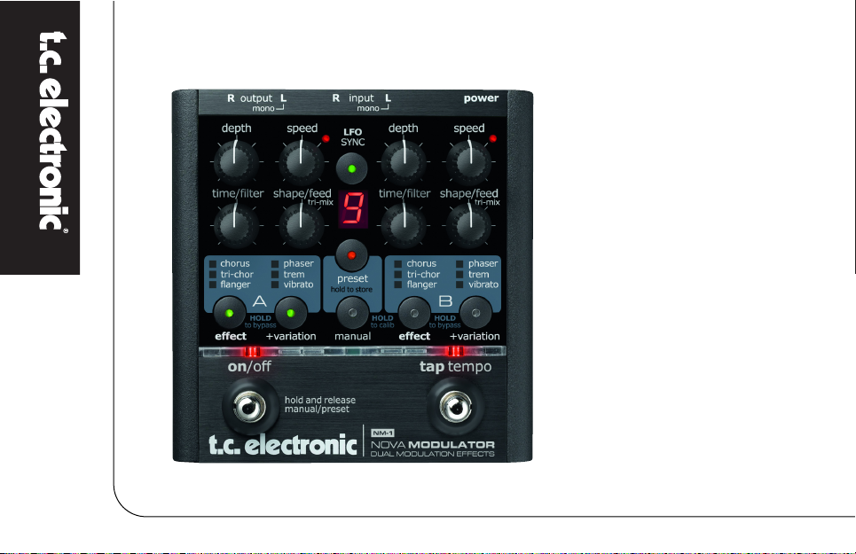
NM-1
NOVA Modulator
USER’S MANUAL
Page 2

Page 3
INTRODUCTION
Table of Contents . . . . . . . . . . . . . . . . . . . . . . . . . . . .3
Introduction . . . . . . . . . . . . . . . . . . . . . . . . . . . . . . . .4
SETUP EXAMPLES
Mono . . . . . . . . . . . . . . . . . . . . . . . . . . . . . . . . . . . . .5
Stereo . . . . . . . . . . . . . . . . . . . . . . . . . . . . . . . . . . . . .6
Modulator in Loop . . . . . . . . . . . . . . . . . . . . . . . . . . .7
Stereo Loop Setup . . . . . . . . . . . . . . . . . . . . . . . . . . .8
OVERVIEW
Overview . . . . . . . . . . . . . . . . . . . . . . . . . . . . . . . . . .9
Connections . . . . . . . . . . . . . . . . . . . . . . . . . . . . . . .10
Controls . . . . . . . . . . . . . . . . . . . . . . . . . . . . . . . . . .10
EFFECT TYPES
Chorus . . . . . . . . . . . . . . . . . . . . . . . . . . . . . . . . . . .14
Tri-Chorus . . . . . . . . . . . . . . . . . . . . . . . . . . . . . . . .15
Flanger . . . . . . . . . . . . . . . . . . . . . . . . . . . . . . . . . . .16
Through Zero Flanger . . . . . . . . . . . . . . . . . . . . . . .16
Phaser . . . . . . . . . . . . . . . . . . . . . . . . . . . . . . . . . . .19
Tremolo . . . . . . . . . . . . . . . . . . . . . . . . . . . . . . . . . .21
Vibrato . . . . . . . . . . . . . . . . . . . . . . . . . . . . . . . . . . .24
TABLE OF CONTENTS
3
ADDITIONAL FEATURES
Two Engines . . . . . . . . . . . . . . . . . . . . . . . . . . . . . . .25
LFO Sync . . . . . . . . . . . . . . . . . . . . . . . . . . . . . . . . .25
LFO Trigger . . . . . . . . . . . . . . . . . . . . . . . . . . . . . . .27
PRESETS
Preset modes . . . . . . . . . . . . . . . . . . . . . . . . . . . . . .28
Preset mode . . . . . . . . . . . . . . . . . . . . . . . . . . . . . . .28
Bank mode . . . . . . . . . . . . . . . . . . . . . . . . . . . . . . . .29
Limiting the Number of Presets . . . . . . . . . . . . . . . .30
Store . . . . . . . . . . . . . . . . . . . . . . . . . . . . . . . . . . . . .31
APPENDIX
Calibrating Input Sensitivity . . . . . . . . . . . . . . . . . . .32
Technical Specifications . . . . . . . . . . . . . . . . . . . . . .33
TC Electronic, Sindalsvej 34, DK-8240 Risskov – info@tcelectronic.com
Manual revision 1.0 – SW – V 1.0
Prod. No: E60508311
English Version
Page 4
4
Nova Modulator – Creativity Enhanced
Never before have all of TC’s acclaimed modulation effects been packed into a single stompbox. With seven stellar
effects including the brand new Tri-Chorus and Through-Zero-Flanger, Nova Modulator gives you all the modulation
effects you’ll ever need – and then some. This is an effects pedal for the guitarist who has come to terms with the
basics of guitar effects and is now on the lookout for the icing on the cake. With its Dual Engine design, Nova
Modulator allows you to combine Chorus, Flanger, Phaser, Tremolo and Vibrato effects, sync the tempo between
them and even trigger the LFO to start right on the beat. Nova Modulator gives you unlimited sound shaping
possibilities. And with nine presets, there is plenty of room to store your favorite settings.
Destined to spark new inspiration for your music
Nova Modulator Features
• Seven studio-quality modulation effects
• Dual Engine design
• 9/18 user-programmable presets
• LFO synchronization
• LFO trigger
• Tap tempo
• Auto input gain adjustment
• Stereo in/out
INTRODUCTION
Page 5
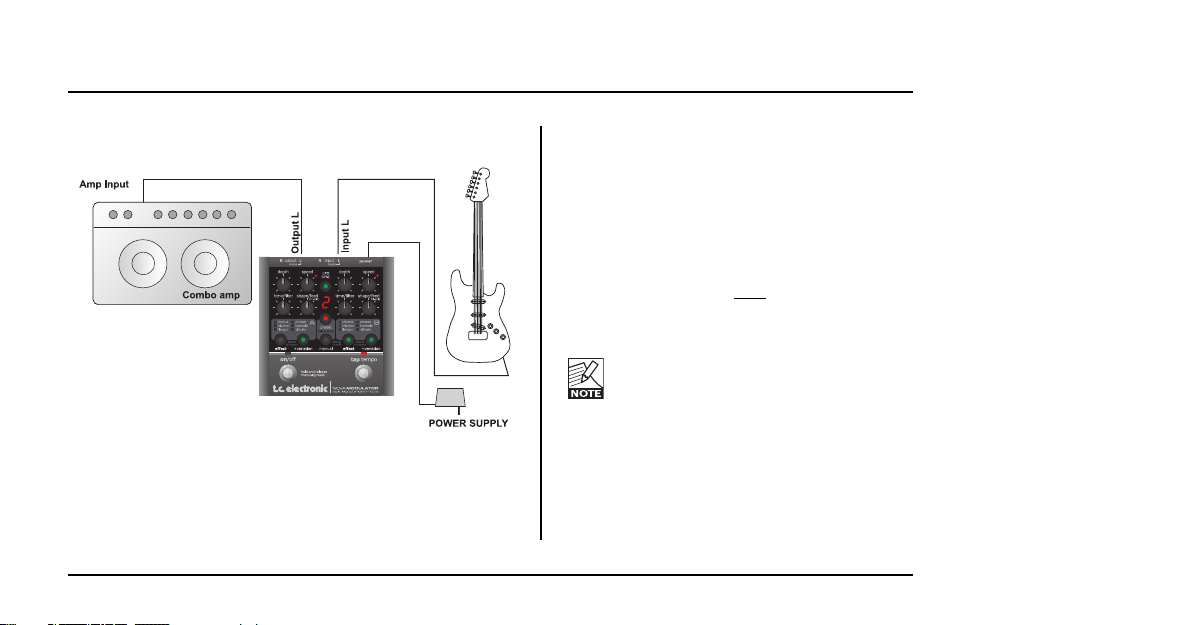
SETUP EXAMPLE: MONO
5
This is a standard mono setup consisting only of
your guitar, your amp and the NOVA Modulator.
• Connect your guitar to the left input (L) of the
NOVA Modulator.
• Connect the left output (L) of the NOVA
Modulator to the input of your amp.
We recommend placing the NOVA Modulator
pedal in the signal path af
ter distortion/overdrive
pedals.
For best signal to noise ratio, calibrate
the pedal according to the level of the
input signal. For further information, refer
to this manual’s “Calibration” section.
Page 6
6
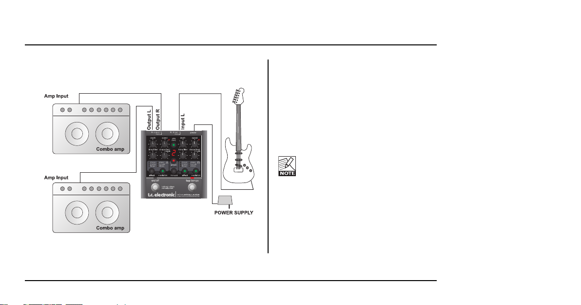
SETUP EXAMPLE: STEREO
This is a classic stereo setup, giving you all
the benefits of the NOVA Modulator’s stereo
effects.
• Connect your guitar to the left input (L) of
the NOVA Modulator.
• Connect the left output (L) of the NOVA
Modulator to the input of one amp, and
the right output (R) to another amp.
For best signal to noise ratio, calibrate
the pedal according to the level of the
input signal. For further information,
refer to this manual’s “Calibration”
section.
Page 7
7
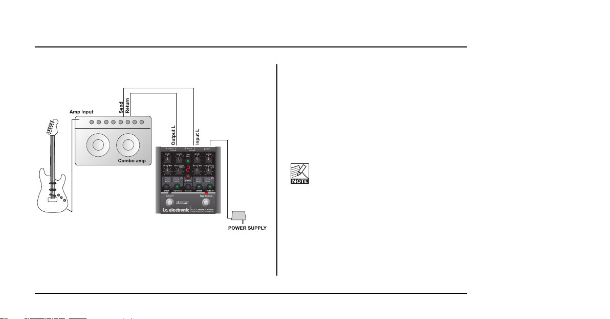
SETUP EXAMPLE: MODULATOR IN LOOP
In this setup, we operate the NOVA Modulator in
the effects loop of a combo amp (i.e., after the
preamp section, before the power amp).
• Connect your guitar to the amp’s input.
• Connect the amp’s effect send to the left
input of the NOVA Modulator.
• Connect the left output of the NOVA
Modulator to the amp’s effect return.
For best signal to noise ratio, calibrate
the pedal according to the level of the
input signal. For further information, refer
to this manual’s “Calibration” section.
Page 8
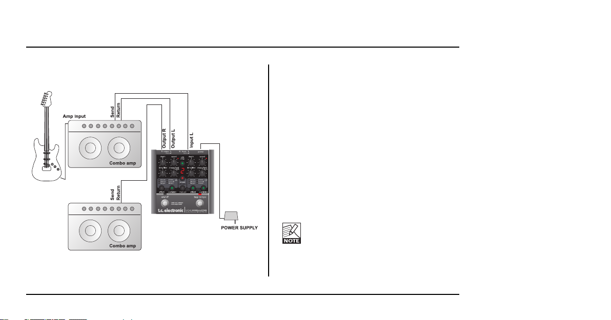
SETUP EXAMPLE: STEREO LOOP SETUP
8
In this setup, we use the pre-amp from one of
the combo amps to generate the basic sound
and the NOVA Modulator to split the signal into
stereo. Please note that by connecting one of
the Modulator’s outputs to the return jack of amp
B, we only use the power amp section of that
second amp.
• Connect your guitar to the input of amp A.
• Connect amp A’s effect send to the left input
of the NOVA Modulator.
• Connect the left output of the NOVA
Modulator to amp A’s effect return.
• Connect the left output of the NOVA
Modulator to amp B’s effect return.
For best signal to noise ratio, calibrate
the pedal according to the level of the
input signal. For further information, refer
to this manual’s “Calibration” section.
Page 9
OVERVIEW
9
NOVA MODULATOR
DUAL MODULATION EFFECTS
inputoutputRRLL
power
mono mono
hold and release
manual/preset
on/off
tap tempo
speed
LFO
SYNC
speed
shape/feed shape/feed
tri-mix tri-mix
effect effect
depth depth
time/filter time/filter
flanger flangervibrato vibrato
HOLD
to bypass
HOLD
to calib
HOLD
to bypass
tri-chor tri-chortremolo tremolo
chorus chorusphaser phaser
+variation +variation
AB
manual
preset
hold to store
Page 10

10
OVERVIEW
This section describes in short the functions of the
knobs and buttons on the NOVA Modulator. For
detailed explanations of the various parameters, please
refer to the manual section describing the effects.
Connections
1 – Power
The NOVA Modulator requires 12V DC 300 mA. Use
the power supply provided in the product box or a
power supply with similar specifications.
2 – Inputs
These are ¼" mono jack connectors for signal input.
NOVA Modulator will sense if a signal source is
connected to both inputs and treat these signals as
one stereo source. If you connect a mono source only
,
ALWAYS use the left input!
3 – Outputs
These are ¼" mono jack connectors which carry the
signals from channels A and B.
Controls
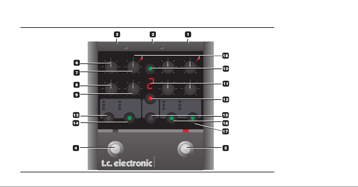
4 – ON/OFF Switch
The ON/OFF switch has several functions.
• Press the ON/OFF switch once to bypass or
activate the pedal.
• Press and hold the ON/OFF switch for
approximately 0.5 seconds to alternate between
Manual mode and Preset mode.
5 – TAP TEMPO Switch
Tap this switch rhythmically to enter the global tempo.
Typically, you will tap quarter notes.
Example:
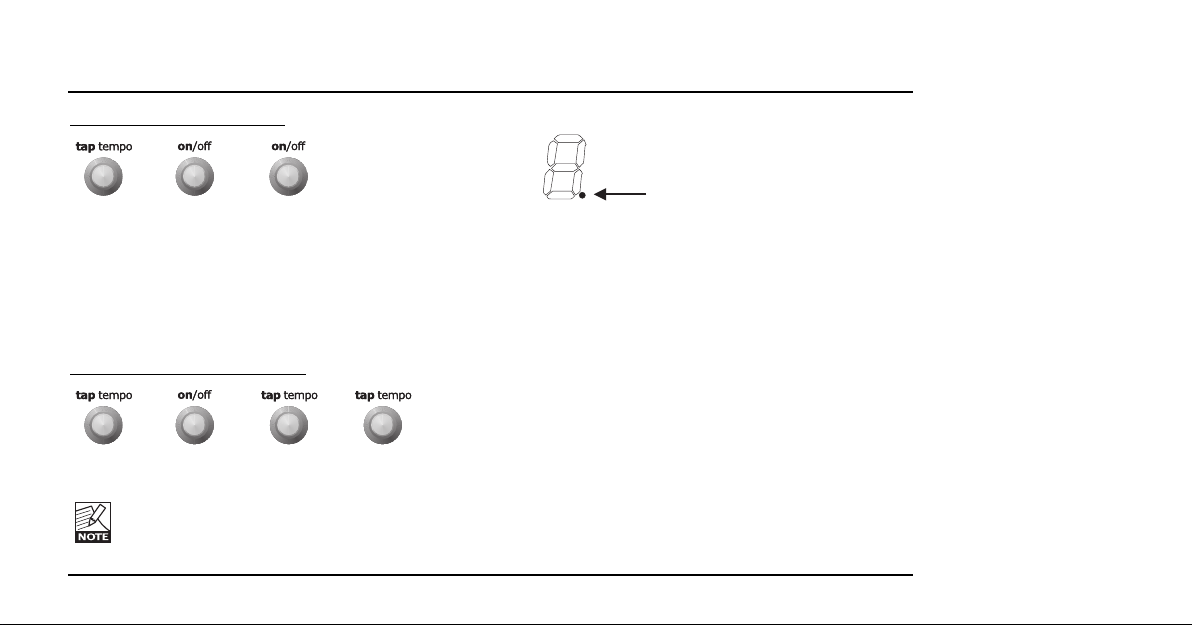
Preset selection using the ON/OFF and the
TAP TEMPO switches
When you are in Preset mode, you can step through
presets by pressing the PRESET button repeatedly.
The same function can be invoked by first pressing the
TAP/TEMPO switch once and immediately thereafter
pressing the ON/OFF switch multiple times.
Page 11
11
OVERVIEW
Illustration - step up in presets
1 2 3 etc.
You can even scroll downwards using the foot
switches: Press TAP TEMPO once, followed by one
tap on the ON/OFF switch. Then press the TAP
TEMPO switch again on or more times. Now you scroll
downwards through the preset list.
Illustration - step down in preset
s
1 2 3 4 etc.
The dot in the lower right corner of the display
indicates when toggle modes active. As long the
dot is lit, it is possible to step up/down in
presets as described above.
Edited dot
6 – DEPTH Knob
The DEPTH knob operates as a standard depth control
for all effect types.
- In the Chorus, Tri-Chorus Flanger and Vibrato
effects the knob controls the pitch depth.
- In the Phaser effect, the knob controls the filter
depth.
- In the Tremolo effect, the knob controls the amount
of volume attenuation, also known as the intensity
of the tremolo.
7 – SPEED Knob
The SPEED knob operates as a standard speed
control for all effect types.
Page 12

8 – TIME/FILTER Knob
The function of this knob depends on the selected
effect type:
Chorus: Chorus delay time
Tri-Chorus: Chorus delay time
Flanger: Flanger delay time
Phaser: 4, 8 or 12 filters (indicated in the display)
Tremolo: Subdivision (indicated in the display)
Vibrato: Ramp time*
* Ramp: This is a function available in Variation mode that,
when activated, gradually increases the depth of the Vibrato,
similar to what a vocalist does.
9 – SHAPE/FEED/TRI-MIX Knob
The function of this knob depends on the selected
effect type:
Chorus: Hi-Cut
Tri-Chorus: Chorus mix (amount)
Flanger: Flanger Feedback
Phaser: Phaser Feedback
Tremolo: Pulse-width
10 – LFO SYNC Button
The LFO Sync function syncs the speed of effect
Engines A and B. With LFO Sync activated (LED lit),
tapping the tempo on the TAP TEMPO switch will sync
both Engines to this tapped tempo. For the Tremolo
effect it is possible to select the sub-division using the
TIME knob. This is explained further in the “Effects”
chapter in this manual.
11 – Display
The 7-segment display may indicate different
parameters:
• Either the current preset number or
• The number of filters (for the Phaser) or
• The Subdivision (for the Tremolo)
The dot in the lower right corner can indicate:
• When a knob is placed at the currently stored
position
• When the pedal is in preset toggle mode
OVERVIEW
12
Page 13

12 – PRESET Button
Press the PRESET button once to enter Preset mode.
Press it several times to step through presets. In
Preset mode, you can store and recall up to nine
different presets. In bank mode up to 18 (2x9) presets
can be stored.
Please also refer to the section “Limiting the Number of
Presets” in chapter “Presets” of this manual.
13 & 16 – EFFECT Buttons
Use the EFFECT buttons to switch the two effects on
or off individually and to set the effect type for each
Engine. Press an EFFECT button once to engage that
effect’s Engine. Press and hold an EFFECT button to
disengage that Engine. Please note that it is not
possible to disengage both Engines at the same time.
If only one Engine is active and you disengage that
Engine, NOVA Modulator will automatically engage the
other Engine.
If you want to fully switch off both Engines (i.e., bypass
the pedal), use the ON/OFF switch.
Press an EFFECT button several times to select
between the different effect types. The available types
are Chorus, Tri-Chorus, Flanger (LED red), ThroughZero-Flanger (LED green), Phaser, Tremolo and
Vibrato.
14 & 17 – VARIATION Buttons
The various effect types have so-called variations.
E.g., for the Tremolo, there are “hard” and “soft” types.
The Chorus has phase tilts. You will find additional
information on these variations in the manual section
describing the effects.
18 – SPEED LEDs
When LFO SYNC mode is not active
, you can change
the speed of the two engines individually using the
SPEED knobs and the TAP TEMPO switch.
Only one Engines SPEED LED will be lit at any time as
the TAP TEMPO switch directly controls the tempo of
the other Engine.
(See also the “LFO Sync mode “off” example on page
26).
When LFO SYNC mode is active
, the same speed is
applied to both Engines. In this case, the speed is
OVERVIEW
13
Page 14

controlled either by Engine A’s SPEED knob or by
tapping the TAP TEMPO switch. When you set the
speed using Engine A’s SPEED knob, the SPEED LED
in Engine A indicates the tempo. When you set the
tempo by tapping it with the TAP TEMPO switch, the
TAP TEMPO switches’ LED indicates the tempo.
In LFO Sync mode, the SPEED knob of Engine
B is inactive!
Chorus
Introduction
The basic idea of a Chorus effect is to split the signal
and pitch modulate one of the signals slightly, then mix
the two signals again. In this “regular” type of Chorus,
the Chorusing effect occurs when the pitch modulated
signal is played against the dry signal.
DEPTH Knob
Use the DEPTH knob to specify the intensity of the
effect. The more you turn the knob clock-wise, the more
“out of tune” the modulated part of the signal will be.
EFFECT TYPES: CHORUS
14
Page 15

EFFECT TYPES: CHORUS
15
SPEED Knob
Use the SPEED knob to set the speed of the effect.
The relationship between the depth and
speed parameters is important. The faster the
speed, the less depth can be applied before
the Chorus sounds “out of tune”.
TIME/FILTER Knob: Time Parameter
Use the TIME/FILTER knob to set the delay time for
the Chorus effect. Changing the delay time will change
the perceived “width” of the Chorus effect. Set this
knob to a 12 o’clock position for a nice traditional
Chorus effect.
SHAPE/FEED Knob: Hi-Cut Parameter
Use the SHAPE/FEED knob to reduce the high-end
frequencies in the Chorus effect. Try using this
parameter if you feel the Chorus effect is too dominant
in your sound.
VARIATION Button
Use the VARIATION button to tilt the phase of the
signal on the right channel by 90 degrees, resulting in
a very broad stereo sound.
This only applies in stereo setups.
Tri-Chorus
Introduction
The Tri-Chorus is a variation of the regular Chorus that
uses three stereo Choruses with various offsets for
both depth, speed, phase and chorus delay time to
produce a unique, very broad and lush Chorus sound.
Speed, Depth and Time parameter descriptions are
similar to the standard Chorus descriptions.
SHAPE/FEED/TRI-MIX Knob: Tri-Mix Parameter
In Tri-Chorus mode, use the SHAPE/FEED/TRI-MIX
knob to set the mix between the dry signal and the
chorused effect.
Page 16

16
EFFECT TYPES: CHORUS
+VARIATION Button
Two phase settings are available for the Tri-Chorus.
One option produces a more traditional Chorus sound
where the phases of the three Choruses are tilted by
90, 180 and 270 degrees respectively. The other option
is an asymmetric type where the phase and depth
parameters are tuned to produce a wilder and more
“uncontrolled” Chorus effect.
Flanger
Introduction
The Flanger belongs to the same “family” of
modulation effects as the Chorus effect. The signal is
split, and one of the signals is pitch modulated.
The characteristic “flanging” sound occurs when the
pitch-modulated part of the signal is slightly delayed
and fed back to the input of the effect algorithm. In a
Flanger effect, the delay times of the modulated signal
are typically shorter compared to a Chorus effect.
Experiment with the Feedback parameter to get an
idea of the effects you can achieve.
Normal or TZF (Through Zero Flange) mode
Two Flanger modes are available. To select the Flanger,
press the EFFECT button repeatedly. The LED will turn
red, indicating Normal mode. Press the EFFECT button
once more, and the LED will turn green, indicating TZF
mode. The TZF mode emulates the original way of
creating a flange effect, with two identical pieces of
audio material being played back simultaneously on
two tape decks and then being mixed on a third deck.
The flanging effect was achieved by slowing down and
speeding up the two decks at different times. An
essential part of the special effect created this way is
the unique phase cancellation occurring when the two
signals pass each other in time (the zero point). A
conventional Flanger pedal/ algorithm tries to emulate
this effect, but because the two signals will never cross
each other in time, until now, phase cancellation wasn’t
possible.
But with the NOVA Modulator ’s TZF mode, it is.
DEPTH Knob
Use the DEPTH knob to set the intensity of the effect.
The more you turn the knob clock-wise, the more “out of
tune” the modulated part of the signal is.
Page 17

17
EFFECT TYPES: FLANGER
SPEED Knob
Use the SPEED knob to set the speed of the effect.
SHAPE/FEED Knob: Feedback Parameter
Use the SHAPE/FEED knob to control the amount of
feedback (Resonance) of the short modulated delay
that causes the Flanging effect. When the Feedback is
set too high (above approximately 90 % to 95 %), this
might introduce internal feedback, resulting in a
squealing noise that in most cases is unwanted in
flanging effects. Be aware of this side-effect when
experimenting at high volumes. Negative values
inverse the phase of the signal that is fed back to the
algorithm’s input.
Negative Feedback Positive Feedback
Although the NOVA Modulator effects have
been tuned to sound great with the knobs in 12
o’clock position you should notice that setting
the FEEDBACK knob to the 12 o’clock position
results in NO feedback. For traditional pedal
flanging sounds, this will sound a little tame, so
you should use at least some feedback.
If, on the other hand, you have selected TZF
mode and are aiming for the most authentic
through-zero-flange sound, you should try
setting the feed-back knob exactly at the 12
o’clock position.
TIME/FILTER Knob: Flanger Delay Parameter
Typically, delay values around 5 ms are used for
flanging effects, whereas Chorus effects occur with
delay times around 10 ms. Short delay times give very
intense, “jet engine”-type sounds. Longer delay times
give more “bathroom”-type sounds.
Page 18

18
EFFECT TYPES: FLANGER
+VARIATION Button
The +VARIATION button allows you to select between
two distinct flavors of tape flanging effects: negative
and positive summing.
The button essentially flips the phase of the "flanged"
signal 180 degrees, creating radically different sounds
particularly when the two signals are mixed together.
With negative summing (+VAR “off”) the delayed signal
is phase reversed resulting in severe frequency
cancellations as the two signals get closer to the zero
point. When the two signals are exactly at the same
point they will cancel out each other completely.
Positive summing (+VAR “on”) happens when the
delayed signal is in phase with the dry signal. When
mixed the result is a warm, less extreme, but very
musical sound that gets more pronounced as the
delayed signal gets closer to the zero point.
Page 19

19
EFFECT TYPES: PHASER
Phaser
Introduction
The electronic phasing effect is created by splitting an
audio signal into two paths. One path treats the signal
with an all-pass filter, which preserves the amplitude of
the original signal and alters the phase. The amount of
change in phase depends on the frequency. When
signals from the two paths are mixed, the frequencies
that are out of phase will cancel each other out,
creating the “notches” characteristic for a Phaser.
Changing the mix ratio changes the depth of these
notches. The deepest notches occur when the mix
ratio is 50 %, which is the fixed ratio of the Phaser in
NOVA Modulator.
DEPTH Knob
Use the DEPTH knob to specify the intensity of the
effect. The higher the setting the more aggressive the
effect will sound.
SPEED Knob
Use the SPEED knob to set the speed of the effect.
SHAPE/FEED Knob: Feedback Parameter
Use the SHAPE/FEED knob to control the amount of
feedback in the Phaser. Negative values inverse the
phase of the signal that is fed back to the algorithm’s
input.
Negative Feedback Positive Feedback
Page 20

20
EFFECT TYPES: PHASER
Although the NOVA Modulator effects have
been tuned to sound great with the knobs in 12
o’clock position you should note that setting the
FEEDBACK knob to the 12 o’clock position with
the Phaser selected results in NO feedback.
This may sound too tame compared to
traditional stomp box pedal phasers. Experiment
with either positive or negative settings.
TIME/FILTER Knob: Filter Parameter
Use the TIME/FILTER knob to set the number of filters
used for the phaser. The variations are 4, 8 or 12
filters. The display will indicate the number of filters
while you turn the knob. The fewer filters, the more
“grainy” the effect. The more filters are used, the
smoother the effect sounds.
Indication
4 – filters 8 – filters 12 – filters
Most “old-school” pedals use four filters.
+VARIATION Button
Use the VARIATION button to shift between high and
low emphasis.
When the LED is “on” the emphasis is on the
high frequencies. This gives a subtle,
transparent Phaser that is not too dominant.
When the LED is “off” the emphasis is on the
low-end frequencies and the phasing sound is a
more pronounced, grindy “old-school” type.
Page 21

21
Tremolo
Introduction
The Tremolo effect periodically increases and
decreases the level of the signal. With this particular
Tremolo, you can choose between soft(sine) and hard
(square) curves. You can also change the pulse width.
DEPTH Knob
Use the DEPTH knob to set the intensity of the effect.
A 100 % setting means that the signal is completely
muted between signal peaks.
SPEED Knob
Use the SPEED knob to set the speed of the effect.
TIME/FILTER Knob: Time Parameter
Use the TIME/FILTER knob to set the subdivisions of
the global tempo used for the Tremolo effect. The
options are:
EFFECT TYPES:TREMOLO
Set the knob in this range for 1/4 (quarter
notes)
The display will show
Set the knob in this range for 1/4 triplets
The display will show
Set the knob in this range for 1/8
The display will show
Page 22

22
EFFECT TYPES:TREMOLO
Set the knob in this range for 1/8 triplets
The display will show
Set the knob in this range for 1/16
The display will show
Set the knob in this range for 1/16 triplets
The display will show
SHAPE/FEED Knob: Pulse-width Parameter
Use the SHAPE/FEED knob to set the width of the pulse.
Example – narrow peaks with a “hard” waveform
Knob position Waveform
Example – classic symmetric tremolo
Knob position Waveform
Example – wide peaks with a “hard” waveform
Knob position Waveform
Page 23

23
+VARIATION Button
Two waveforms are available as modulation sources
for the Tremolo effect. Using the “Hard” option results
in a steeper effect. Listen and choose the appropriate
option.
Soft
Hard
For a 100 % “on/off” kind of Tremolo, choose
“Hard Tremolo” and turn the DEPTH knob fully
clockwise.
EFFECT TYPES:TREMOLO
Page 24

Vibrato
Introduction
The Vibrato effect modulates the pitch of the incoming
signal. The result is similar to the vibrato technique
used by vocalists. In contrast to a Chorus or Flanger
effect, no direct signal is combined with the pitchmodulated signal.
DEPTH Knob
Use the DEPTH knob to specify the intensity of the
effect. The setting represents the amplitude of the
modulating waveform.
The higher the amplitude the more the pitch is
modulated.
SPEED Knob
Use the SPEED knob to set the speed of the effect.
TIME FILTER Knob
This knob sets the Ramp time in when +VARIATION is
activated. Read more below.
SHAPE/FEED Knob
Use the SHAPE/FEED knob to set the frequency of the
high-cut filter applied to the signal. Adding high-cut on
a vibrato results in a more subtle, vintage sounding effect.
VARIATION Button
With the VARIATION button activated, you can hold the
TAP TEMPO switch to activate/deactivate the Vibrato
function AND the “Ramp” function. In this mode, the
TAP TEMPO button works as a latching switch for
turning the effect on/off.
The Ramp Function:
When you have activated the Ramp function, you can
press and hold the TAP TEMPO switch to start the
vibrato with only little depth and “ramp up” until the
maximum vibrato setting is achieved. You can set the
maximum vibrato depth using the DEPTH knob. Set
the Ramp Time using the TIME/FILTER knob.
EFFECT TYPES: VIBRATO
24
Page 25

ADDITIONAL FEATURES
25
Two Engines
NOVA Modulation contains two identical effect
Engines. This allows you to use two different
modulation effects at the same time, or to even
combine two identical algorithms for a more extreme
and pronounced effect.
But for a more traditional effect – or to listen to only
one effect at a time when creating a new preset –
either Engine can be turned off by pressing an holding
the EFFECT button for approximately 500 ms.
Pressing the EFFECT button again (in this case,
holding is not necessary) turns the Engine on again.
LFO Sync
What is an LFO?
The LFO (Low Frequency Oscillator) is an audio signal
with a very low frequency that creates a pulsating
rhythm rather than an audible tone. In the NOVA
Modulator, this rhythm is routed to control the speed of
the various effects.
LFO Sync
• Press the LFO SYNC button to activate this
function.
The LFO Sync function allows synchronization of the
two effect Engines’ Speed parameters. With LFO Sync
activated, tapping the tempo on the TAP TEMPO foot
switch or turning Engine A’s SPEED knob will set both
Engines to the same tempo – i.e. synchronize them.
Use LFO Sync when you want to create pronounced
effects. E.g., you might double two identical Chorus
sounds, sync the tempo of a Tremolo effect to a
Flanger/Phaser or create rhythmic Tremolos by using
two Tremolos with different subdivisions. This feature
really opens up a world of sounds and applications, so
experiment and be creative!
The SPEED Knob in LFO Sync mode
In LFO Sync mode, the SPEED knob on Engine A
becomes a master speed control for both Engines and
disables the SPEED knob on Engine B.
Page 26

Tempo Indication in LFO Sync mode
In LFO Sync mode the tempo is set either by turning the
Engine A SPEED knob or by tapping the TAP TEMPO
switch.
If you set the tempo using the Engine A SPEED knob the
LED next to the SPEED knob will indicate the tempo.
If you tap the tempo using the TAP TEMPO switch, the
TAP TEMPO LED will indicate the tempo.
Switching LFO Sync mode on and off
When switching LFO Sync mode off in Manual mode,
the value of the Speed parameter in Engine B will
change to the current position of Engine B’s SPEED
knob. Engine A will retain the tap tempo speed.
When switching LFO Sync mode off in Preset mode
,
the Speed parameter values of both Engine A and
Engine B will change to the values originally stored in
the preset.
LFO Sync mode “Off”
When LFO Sync mode is “off” it is possible to select
which effects Engine that is controlled using the TAP
ADDITIONAL FEATURES
26
TEMPO switch. This is great if you e.g. want to control
the speed of a tremolo in Engine A, but not the speed
of the chorus selected in Engine B.
Step by step example:
Object: T
AP TEMPO controlling the speed of Engine B
Turn the SPEED knob on Engine A and then tap the
TAP TEMPO switch. You have now set the tempo of
Engine A using the Engine A SPEED knob and the
tempo of Engine B using the TAP TEMPO switch.
• The Engine A Speed LED is showing the tempo (of
Engine A).
• The Tap Tempo LED is showing the tempo of
Engine B.
• The Engine B Speed LED is not lit.
Object: T
AP TEMPO controlling the speed of Engine A
• The Engine B Speed LED now indicates the tempo
of Engine B according to the position of the SPEED
knob.
• The Engine A tempo (that was previously indicated
by the Engine A Speed LED) is now shown in the
Tap tempo LED.
• The Engine A SPEED LED is not lit.
Page 27

LFO Trigger
Every time the NOVA Modulator is switched on using
the ON/OFF switch, the LFO is re-triggered. This is a
nice feature that allows you e.g. to sync the tempo of a
Tremolo to the tempo of a song and to make sure that
the sound is “spot-on” all the time.
Example:
• Bypass the NOVA Modulator.
• Select the Tremolo effect for Engine A and activate
Engine A (the EFFECT switch LED is lit).
• Select e.g. 1/8 as subdivision by setting the
TIME/FILTER knob within this interval:
• Tap the tempo of the song in quarter-notes using
the TAP TEMPO switch.
• Press ON/OFF in tempo, e.g. on the count of
“one”.
The LFO trigger works on all effects. You can
e.g. set a Phaser to start at its lowest point
and peak on the next “one” count.
ADDITIONAL FEATURES
27
Page 28

Preset and Bank mode
The NOVA Modulator has two ways of organizing your
presets. Depending on your application you may
choose either.
Preset mode
This is the default mode in which you can store and
recall up to nine presets. In this mode you can
alternate between the Preset and “Manual”, where the
positions of the knobs always apply.
Selecting Preset mode:
• Enter Calibration mode by holding the MANUAL
button for one second. The PRESET button should
now be steadily lit – if it is flashing; press the
PRESET button once.
• Exit Calibration mode by pressing any other button
than PRESET.
Accessing a Preset:
• Press PRESET to access a preset. You can store
up to nine presets. Each preset holds the
parameter settings for both Engines A and B.
You can not toggle between Engines A and B as
both Engines are always part of a preset,
whether they are active or not.
Selecting preset
s can be done in a couple of ways:
• Press the PRESET button several times to step
through the presets.
• Press the TAP/TEMPO switch once and
immediately after that the ON/OFF button multiple
times.
In Preset mode, you can switch between the current
preset and the manual settings.
Alternating between the two settings can be done in
two ways:
• Press the MANUAL button to access Manual
mode. In this mode, the position of the knobs
always apply.
• Alternate between Manual mode and Preset mode
by holding the ON/OFF button for approximately
one second and then releasing.
PRESETS
28
Page 29

PRESETS
29
Bank mode
Bank mode allows you to store up to nine banks
holding two presets each. This is the mode to use if
you have a number of different songs that require
dedicated presets.
Selecting Bank mode:
• Enter Calibration mode by holding the MANUAL
button for one second. The PRESET button’s LED
should now be flashing. If it is steady lit, press the
PRESET button once.
• Exit Calibration mode by pressing any button other
than PRESET.
The 7-segment display now shows the current preset
bank. For each of the nine banks, you can store two
presets. The presets are dedicated to the PRESET and
MANUAL buttons.
Preset #1 Preset #2
Alternating between the two presets in a bank can be
done in two ways:
• Press the PRESET button (for preset #1) or the
MANUAL button (for preset #2) or
• Press and hold the ON/OFF button for approx. one
second.
Selecting banks can also be done in a couple of ways
:
• You can press the PRESET button several times to
step through the banks or
• You can press the TAP/TEMPO switch once and
immediately thereafter the ON/OFF button multiple
times.
See also the example on how to select presets using
the TAP TEMPO and ON/OFF switches on pages 10-11.
Bank mode differs from Preset mode in the
following ways:
- when the MANUAL buttons LED is lit it means that
preset #2, in the current bank is recalled. Unlike in
Manual mode – you can not rely on the position of the
knobs as an indication of the current parameter values.
Page 30

annoying. Therefore you have the option of limiting the
available preset range – e.g. to four presets.
Example:
Let’s say you want to use only presets 1, 2, 3 and 4.
To do so, set up the pedal as follows:
• Press and hold the MANUAL button for
approximately 500 ms. The unit is now in
Calibration mode.
• Turn the DEPTH knob of Engine B to select the
upper limit of the preset range.
In this case, select “4”.
• Now turn the DEPTH knob of Engine “A” to select
the lower limit of the preset range.
Let us say that you play in two different bands.
With one band you want to use presets 1 to 4;
with your other band, it’s presets 5 to 8. As the
NOVA pedal easily holds eight presets, all you
have to do is change the range for each
session.
PRESETS
30
- When storing a preset in bank mode, only the
modified parameters will be stored. There is no
“overwrite” function.
- The 2x9 presets in Bank mode are completely
separate from the 9 presets in Preset mode.
No presets will be deleted when switching back and
forth between the two modes.
When switching to a new bank NOVA Modulator
is automatically bypassed and preset #1
(PRESET button) is selected, ready to be
activated when you press ON/OFF
Limiting the Number of Presets
As explained in the previous paragraphs, you can cycle
through presets in different ways:
• Either by pressing the PRESET button repeatedly or
• By hitting TAP TEMPO once, followed by the
ON/OFF switch.
However, you may only need e.g. four presets for a
show. In that case, having to scroll through all of the
nine presets to find the one you need would be
Page 31

No presets are deleted when limiting the preset
range. The “hidden” presets can always be
accessed again by increasing the preset range.
Store
First of all please note that no matter if you are in
Preset mode, Bank mode or Manual mode, the display
always shows the last recalled preset.
To Store a Preset in Preset mode
• Press and hold PRESET until the ON/OFF LEDs
flash three times (approx 4 seconds).
• The current settings are now stored in the current
location.
To store a Preset in Bank mode
As explained on the previous page, the Bank Preset
mode holds two presets per bank. The two presets can
be stored individually.
STORE
31
Bank # 2 is selected and the preset
represented by the PRESET button LED is
active.
Press and hold PRESET (approx 4 seconds)
to store the current settings in the same
location.
Bank # 2 is selected and the preset
represented by the MANUAL button LED is
active.
Press and hold PRESET (approx 4 seconds) to
store the current settings in the same location.
Example:
Page 32

32
APPENDIX: CALIBRATING INPUT SENSITIVITY
Input Level Calibration
Your NOVA Modulator pedal is per default set to work
well right out of the box – just as any other “stompbox”
pedal. However, you can optimize the performance of the
NOVA Modulator’s AD/DA converters by calibrating the
input sensitivity. To do so, follow this step-by-step guide:
• Calibration of the input sensitivity should be set
according to the expected maximum input level.
Therefore, you should always start by turning on
boosters and other signal-attenuating equipment
that has been placed before the NOVA Modulator
pedal in the signal chain.
• Press and hold the MANUAL button until the 5
green button LEDs are lit.
• Play using your loudest* sound for a few seconds.
The LEDs will turn off one by one. How many
LEDs are turned off depends on the output of your
guitar. When there seem to be no more changes,
the pedal is calibrated.
• Press any button to exit.
• The calibration process is now complete.
* By “loudest”, we mean the sound with the highest
dynamic content. This is most likely a clean sound,
as by definition overdrive sounds are compressed –
i.e. they have less dynamics.
Page 33

Analog Inputs
Connectors:
Input Type:
Impedance:
Max. Input Level:
Analog Outputs
Connectors:
Max. Output Level:
Output Type:
Impedance:
Sense Input Impedance:
Overall Data
D to A Conversion:
A to A Delay:
Dynamic Range:
THD
Frequency Response:
Crosstalk:
EMC
Complies with:
¼" phone jacks w. mono sense
Single-ended
1 MOhm
10 dBu @ 12V supply
¼" phone jacks with mono sense
10 dBu @ 12V supply
Balanced/Single ended with ground sense
0 Ohm
225 Ohm
24 bit, 128 x oversampling bitstream
1.65 ms
106/98 dB, 20 Hz to 20 kHz
@ Input level 16/-2 dBu, not A-weighted
< -90 dB (0.0032 %) @ 1 kHz, I/O Level
16 dBu, Load > 2400 Ohm
+0.1/-0.2 dB, 20 Hz to 20 kHz
< -100 dB, 20 H z to 7 KHz, < -94 dB,
7 kHz to 20 KHz
EN 55103-1 and EN 55103-2 FCC part 15,
Class B, CISPR 22, Class B
Environment
Operating Temperature:
Storage Temperature:
Humidity:
General
Finish:
Dimensions:
Weight:
Mains Voltage:
Power Consumption:
Warranty
Parts and labor:
32° F to 122° F (0° C to 50° C)
-22° F to 167° F (-30° C to 70° C)
Max. 90 % non-condensing
Anodized aluminum front
Plated and painted steel end caps
130 x 130 x 55 mm
765 g
100 to 240 VAC, 50 to 60 Hz
(auto-select) AC wall adapter.
AC adapter supplies 12VDC
minimum 0.3 A to pedal
<5 W
1 year
Due to continuous development, these
specifications are subject to change
without notice.
33
APPENDIX:TECHNICAL SPECIFICATIONS
Page 34

 Loading...