

Page 1

TC42
BLACK DIAMOND BURNER KIT
TC42.NG03
PACKAGE CONTENTS:
• BURNER PART# TC42.5011832
• BURNER TRAY ASSY PART# TC42.9641
• TUMBLED GLASS PART# 5012.01
• BURNER SHIELD PART# TC42.9642
• PANEL, lower rear PART# 9643
• MANIFOLD ASSY PART# TC42.9640
NOTE: MUST BE USED WITH PORCELAIN PANELS #TC42.PNLPBKB
• PILOT BRACKET PART# 9626
• HARDWARE PKG PART# TC36.HK03
• MEDIA SPACER, rear PART# 9645
• MEDIA SPACER, front PART# 9646
• MEDIA SPACER, center PART# 9647
These instructions are supplementary to the Installation and Operating
Instructions supplied with the replace and should be kept together.
Refer to the Installation and Operating Instructions for proper gas supply,
safety requirements and operating instructions.
IMPORTANT: THESE INSTRUCTIONS
110505-8 TC42.NG03 5056.426.3
ARE TO REMAIN WITH THE
HOMEOWNER
Page 2
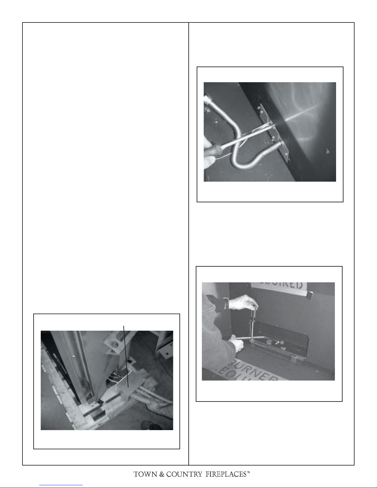
CONTROL BOX RELOCATION
The gas control system is housed in a control box remote of the
replace. Flexible conduits attach the control box to the replace
and house all the plumbing and wiring to the burner.
Although the control box may be installed on the right or left
side, the replace is assembled at the factory to accept the
control box from the right hand side as a default location.
(Fig. # 1)
If installing on the left hand side, the casing and rebox inlet
covers must rst be removed and reinstalled on the opposite
side of the unit. The manifold will also need to be repositioned
before the manifold assembly is installed. This is done by
removing two retaining screws, turning the manifold over and
re-attaching. See Fig. #3. The pilot support bracket, installed
on the burner tray, will also have to be positioned on the left
hand side of the burner tray.
DEFAULT INSTALLATION
Fig. # 2
1) Insert the inlet box into the opening at the base of the right
hand side of the unit, as shown in g # 1, taking care not
to damage pilot, plumbing or wires.
2) Install 4 screws from the inside of the rebox to secure
the inlet box to the rebox.
3) Install Porcelain Panel Set as per instructions.(Refer to
“Porcelain Panels Installation Manual”)
4) Floor panels do not require installation as a burner shield
is provided with the Black Diamond kit.
Fig. # 1
INLET BOX
INSTALL SCREWS TO SECURE INLET BOX
A porcelain panel set must be installed prior to the
installation of the burner assembly. See Installation and
Operating Instructions manual for details.
Fig. # 3
INSERT CONTROL ASSEMBLY
2 TC42.NG03 110505-8
REPOSITION MANIFOLD
Page 3
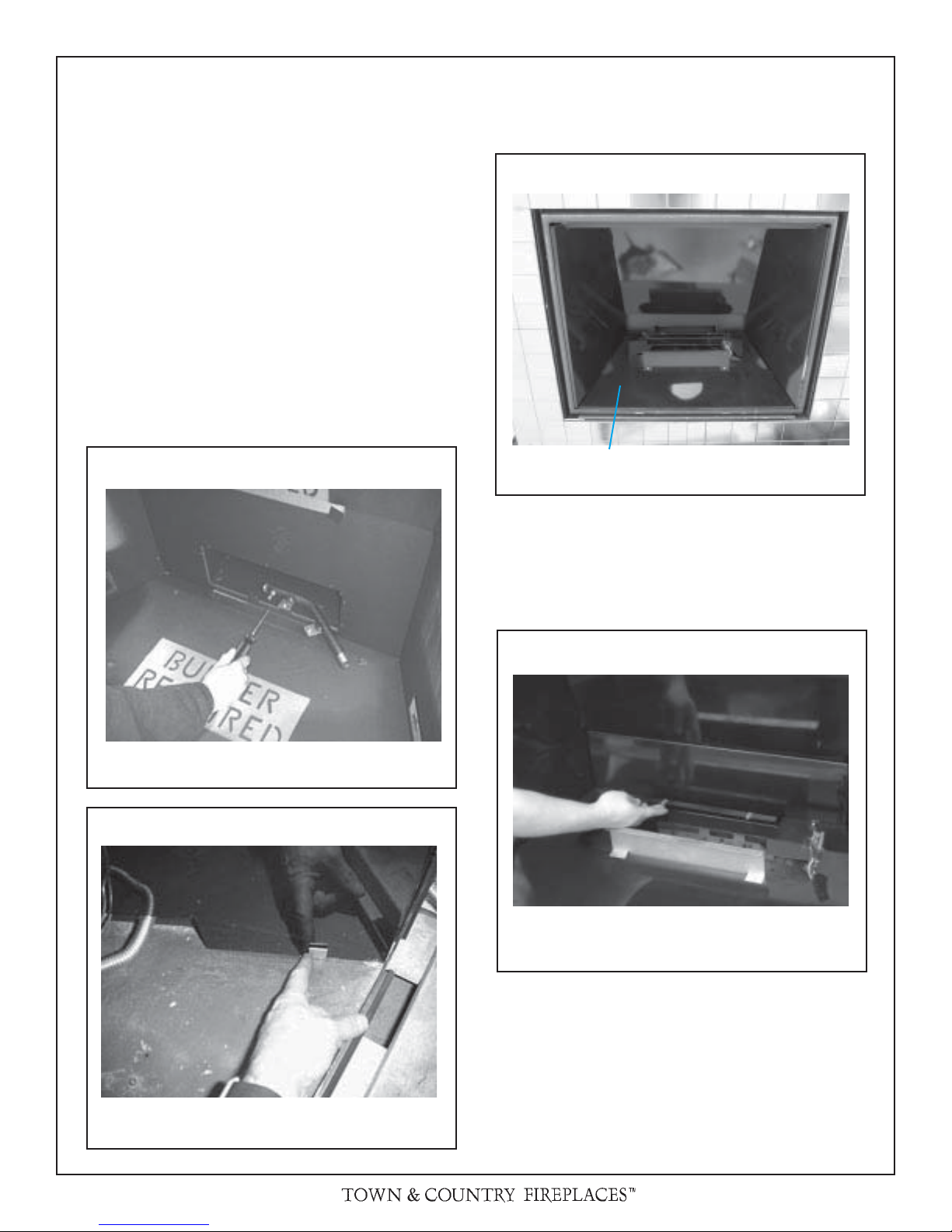
BLACK DIAMOND BURNER INSTALLATION
1) Remove the three lower screws from the air channel at
the back of the rebox and attach the manifold bracket
to the back of the rebox with the three screws as shown
in g. # 4.
2) Panel clips must be installed on the bottom of both side
panels and positioned as shown in Fig. # 5 to insure proper
positioning of burner shield.
3) Install burner shield by tipping the shield into the rebox,
catching the folded edges in the panel clips. (Fig # 6)
4) Position clip nuts, included in hardware package, onto
burner shield. (Fig # 7)
Fig. # 6
Fig. # 4
Fig. # 5
INSTALLING BURNER SHIELD
Fig. # 7
INSTALL MANIFOLD ASSEMBLY
POSITIONING PANEL CLIPS
110505-8 TC42.NG03 3
INSTALLING BURNER SHIELD CLIP NUTS
Page 4
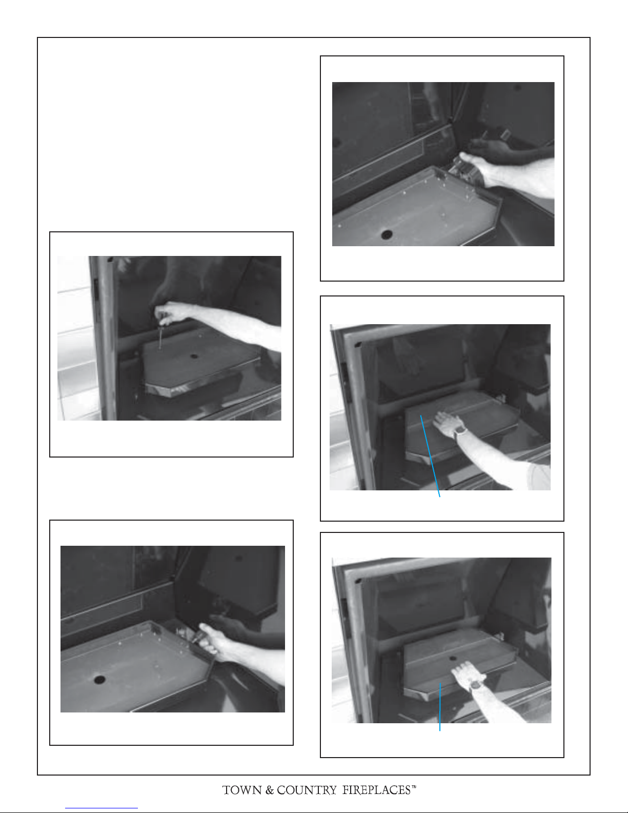
5) Attach the burner tray to the burner shield using two screws
at the back of the tray. (Fig. # 8)
6) Attach the pilot (millivolt shown) to the side of the tray.
(Fig # 9)
7) Attach pilot shield to burner tray with two screws. If using
an electronic control system; attach the pilot to the pilot
shield then attach the shield to the burner tray.
8) Rear and front media spacers are now installed.
(Figs #11 & 12)
Fig. # 8
Fig. # 10
PILOT SHIELD ATTACHMENT
Fig. # 11
Fig. # 9
BURNER TRAY PLACEMENT
REAR MEDIA SPACER
Fig. # 12
PILOT ATTACHMENT
4 TC42.NG03 110505-8
FRONT MEDIA SPACER
Page 5
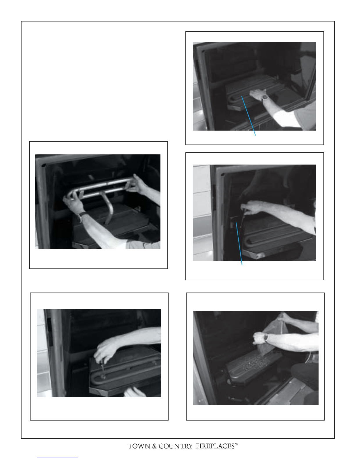
9) Install burner by tilting burner inlet through tray. Ensure
that the ori ce has entered the inlet tube and secure the
burner to the tray with two screws. (Fig # 13a & 13b) Set
the air shutter to fully open for Propane or fully closed for
Natural Gas.
10) Install the center media spacer. (Fig # 14)
11) Install lower rear panel with two screws. (Fig # 15)
12) apply just enough tumbled glass to cover the burner assembly. (Fig # 16)
NOTE: Too much tumbled glass over the burner will
cause sooting with the use of propane gas
Fig. # 13a
Fig. # 14
CENTER MEDIA SPACER
Fig. # 15
Fig. # 13b
BURNER INSTALLATION
BURNER INSTALLATION
LOWER REAR PANEL
Fig. # 16
TUMBLED GLASS PLACEMENT
110505-8 TC42.NG03 5
Page 6
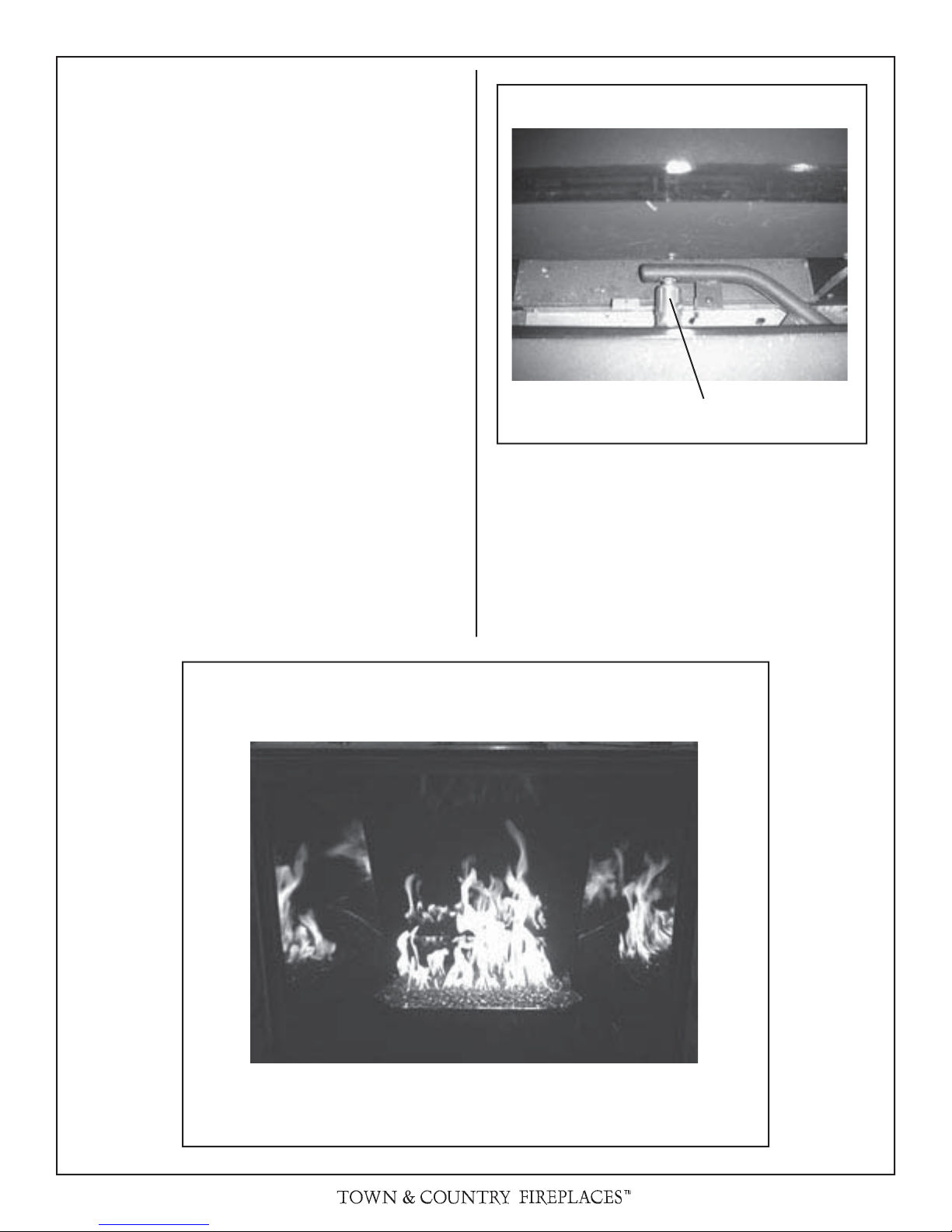
BURNER FLAME ADJUSTMENT
The air shutter on the burner inlet tube controls the primary
combustion air to the gas burner and is preset closed at the
factory for natural gas fuel. Some adjustment may be necessary
to obtain desired ame and to eliminate carbon deposits. Evaluate ame appearance after the replace has reached operating
temperature. See Fig. #17 for proper ame pattern.
Open primary air shutter if the glass, and rebox have carbon
accumulation and/or the ames are long, dark and stringy. The
shutter may also be opened to lessen the ame height.
Caution: Burner area may be hot!
Turn off the replace and allow the unit to cool before proceeding.
To Adjust: (See Fig. # 18)
1) Open and remove window frame and set aside. See
"Window Frame Removal" section found in the Installation
and Operating Instructions manual.
2) Remove the lower rear panel and set aside.
3) Loosen the screw in the Primary Air Shutter.
4) Rotate the shutter to increase or decrease the amount of
primary air.
Fig. # 18
PRIMARY AIR SHUTTER
The ame should be just orange and “lazy”. It should NEVER
be set to create sooting on internal parts and glass.
Fig. # 17
6 TC42.NG03 110505-8
Page 7

REPLACEMENT PARTS
ITEM ..... DESCRIPTION ..................................... PART NO.
1............ BURNER ....................................... TC42.5011832
2.............ORIFICE, NG ......................................... 5022.12
...............ORIFICE, LP ........................................... 5021.31
3.............MANIFOLD STAND ...................................... 9640
4.............MANIFOLD ....................................... TC42.90881
5.............DORMONT FITTING ............................. 5019.221
6.............MEDIA SPACER, FRONT ................. TC42.9646
7.............PILOT SHIELD ............................ TC42.9626PBK
8.............MEDIA SPACER, CENTER ............... TC42.9647
9.............MEDIA SPACER, REAR .................... TC42.9645
10...........TRIM, REAR ............................. TC42.96445PBK
Fig. # 19
1
16
17
ITEM ...... DESCRIPTION ................................... PART NO.
11...........PILOT SUPPORT ......................................... 9625
12...........TRIM, FRONT .............................TC42.9644PBK
13...........SHIELD LEG ................................................9620
14...........PANEL CLIP ................................................. 9610
15...........BURNER SHIELD ......................TC42.9642PBK
16...........TRAY SUPPORT ............................. TC42.96425
17...........PANEL, LOWER RR ...................TC42.9643PBK
18...........BURNER TRAY BOTTOM ...........................9641
...............HARDWARE PACKAGE ................... TC36.HK03
...............TUMBLED GLASS ..................................5012.01
IDENTIFICATION
NUMBER
2
3
4
5
15
14
13
18
12
6
7
8
9
10
11
110505-8 TC42.NG03 7
Page 8

www.townandcountry replaces.net
2975 Allenby Rd., Duncan, BC V9L 6V8
Phone: 1-888-223-0088
Printed in Canada
 Loading...