

Page 1

INSTALLER: Leave this manual with the appliance.
CONSUMER: Retain this manual for future reference.
These instructions are supplementary to the Installation and
Operating Instructions supplied with the replace and should be kept
together. Refer to the Installation and Operating Instructions for proper
gas supply, safety requirements and operating instructions
TC30
CHALET II
BURNER KIT
INSTALLATION
INSTRUCTIONS
PART# TC30.NG06C
For use with:
200411-16 TC30.NG06C 5056.42907
Model TC30
Series C
Page 2
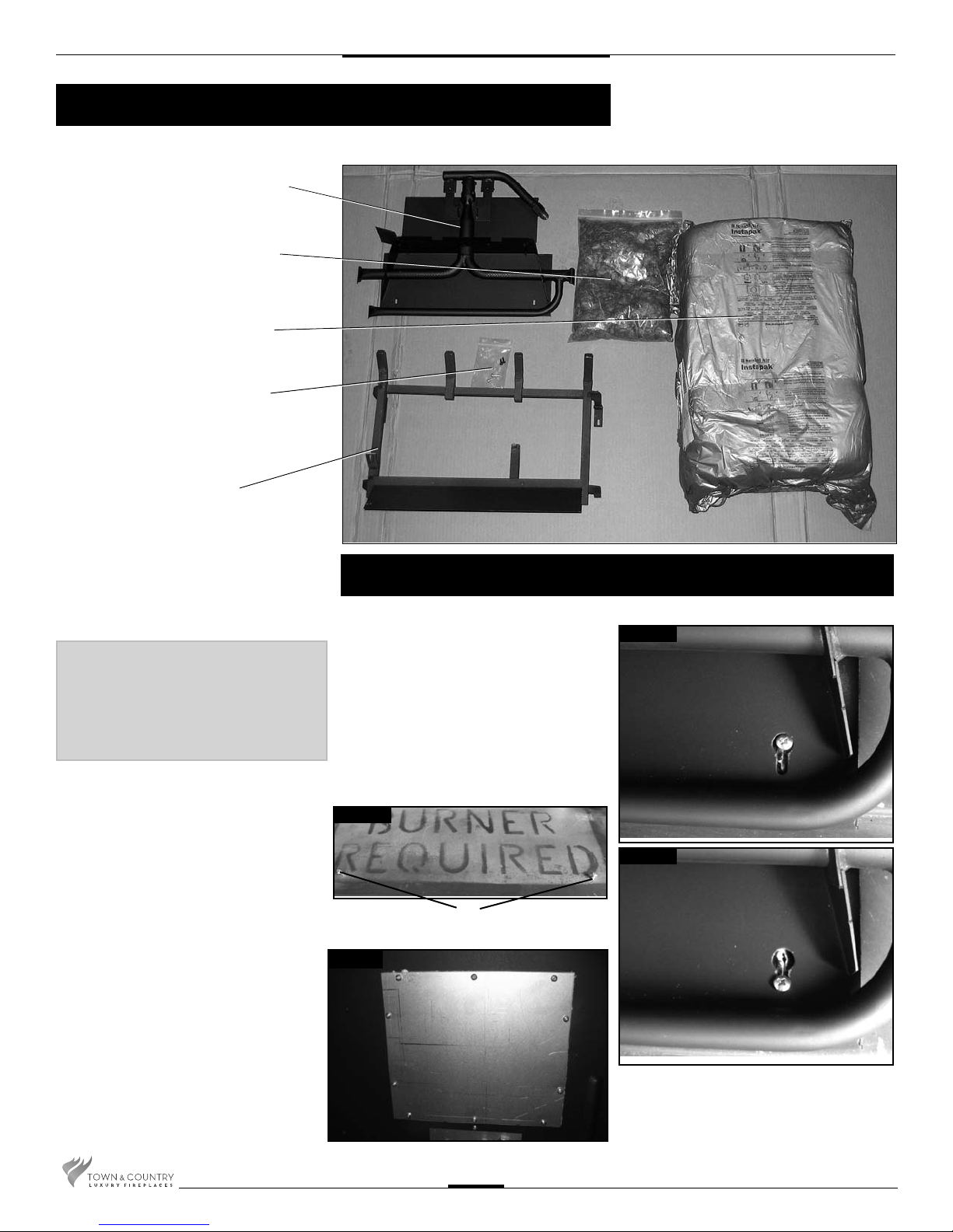
Contents of Package
BURNER ASSEMBLY
EMBER MATERIAL
7 PCS LOG SET
HARDWARE PACKAGE
LOG GRATE
If this replace is to be
used on Propane please
convert prior to installtion.
See pages 9 – 11.
Burner Installation
1. Place the keyhole slots in the burner
over the two screws located in the rebox
base. (Fig. #1 & 1a)
2. Slide the burner back to engage the
screws in the small part of the keyhole
slot and tighten screws. (Fig. #1b)
3. Remove access cover from side of
rebox(Fig. #1c)
Fig. # 1
SCREWS
Fig. # 1c
Fig. # 1a
Fig. # 1b
TC30.NG06C 200411-16
2
Page 3
Burner/ Grate Installation
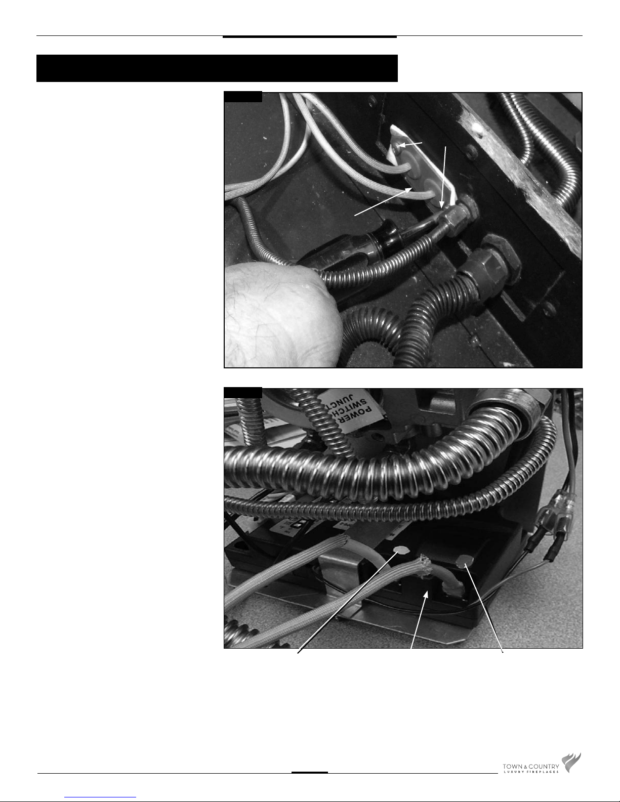
4. Secure the electrical bulkhead plate and
gasket to the rebox. (2 screws) Attach the
ignition and sensor wires to the module.
Red end to the connector marked by the
red dot, white end to the connector marked
by the white dot
Fig.#2 & Fig.#3
Fig. # 2
2 SCREWS
BULKHEAD PLATE
Fig. # 3
WHITE END TO
WHITE DOT
MODULE
RED END TO
RED DOT
TC30.NG06C 200411-16
3
Page 4
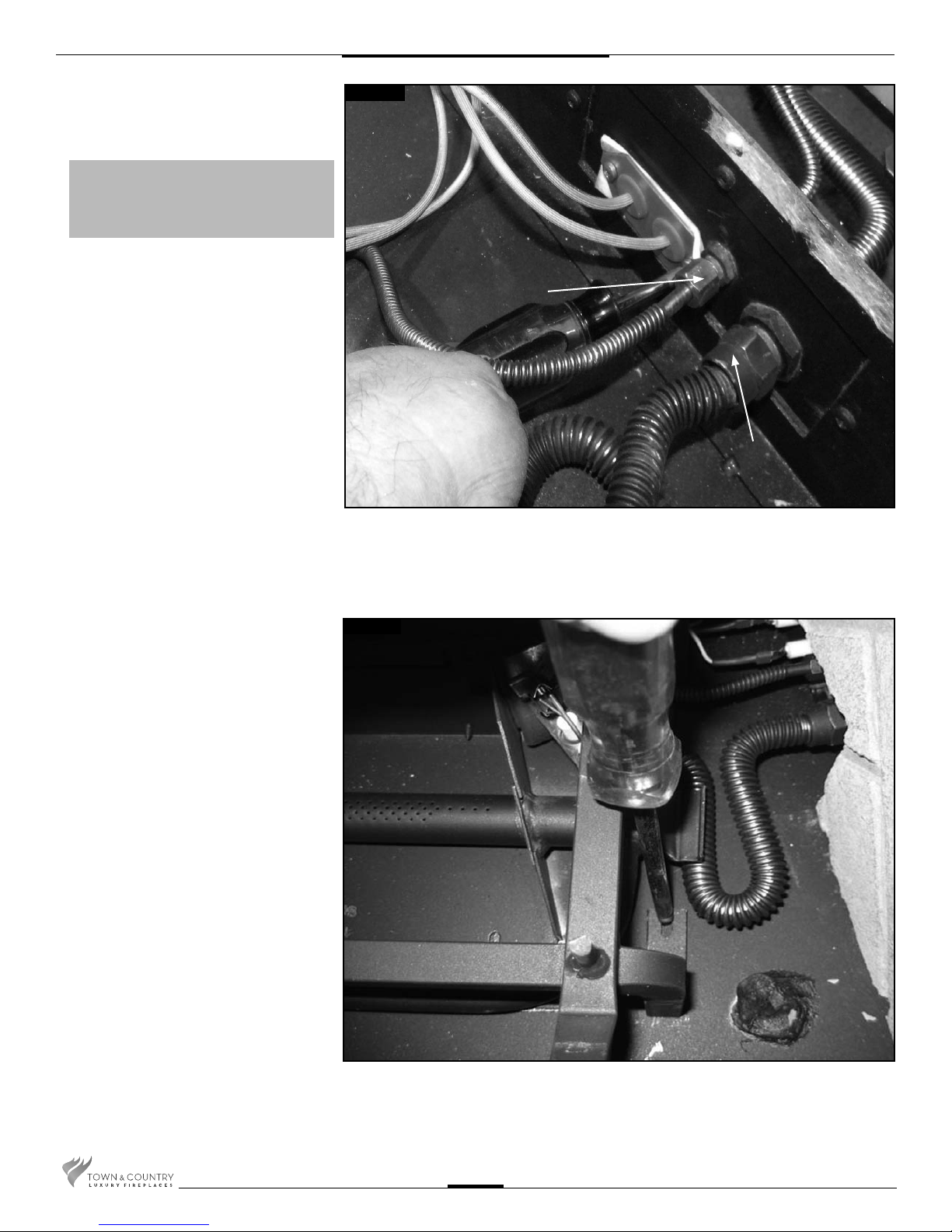
5. Attach the pilot and gas supply tubes to
the bulk head tting and tighten.
(Fig. # 4) Ensure the connections are
gas tight. Conceal the spark and
sensor wires below the supply tubes.
A panel set must now be installed. See
Installation and Operating Instructions
manual for details.
Fig. # 4
PILOT SUPPLY
TUBE
MAIN GAS SUPPLY
TUBE
6. Position the slots of the grate securing
brackets over the holes in the oor shield
and secure with the two screws
(Fig. # 5).
Fig. # 5
TC30.NG06C 200411-16
4
Page 5
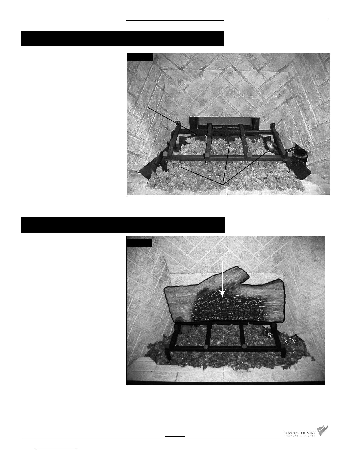
Ember Material
A large bag of ember material is shipped
with the replace and needs to be
installed on the burner to ensure optimum
performance and ame appearance.
1. Pull apart the material into ember size
pieces (approximately 1” square) and
gently place them into the burner pan.
Do not compress, leave them loose for
best performance.
2. Fill the burner pan level with the top of
the pan at rear, and gradually sloping
forward down to the rebox oor at the
front, covering both burner tubes.
3. Place remaining ember material outside
of the burner pan as desired to cover-up
gas lines and brackets.
Note: Ember material placement and
amount will affect ame appearance. More ember material results
in lower flame height. Add or
remove as needed until desired
ame affect.
Fig. # 6
Ember Material Placement
LOG
GRATE
GLOWING EMBERS
Log Set Assembly
Gas plumbing and vent connections should
be completed before proceeding.
The logs are are fragile and should be
handled with care. Unpack and inspect
log set. There should be a total of 7 logs.
Position the logs as indicated by the following
pictures. Place the rear log back against the
tabs located at the back of the grate. Place
left log as pictured, engaging the pins with
corresponding holes on the underside of
the log. Install the right log into the grate
and pull it forward into position as shown.
Place the four remaining small logs on the
oor of the rebox in the positions and order
as shown.
Fig. # 7
LOG #1
TC30.NG06C 200411-16
5
Page 6
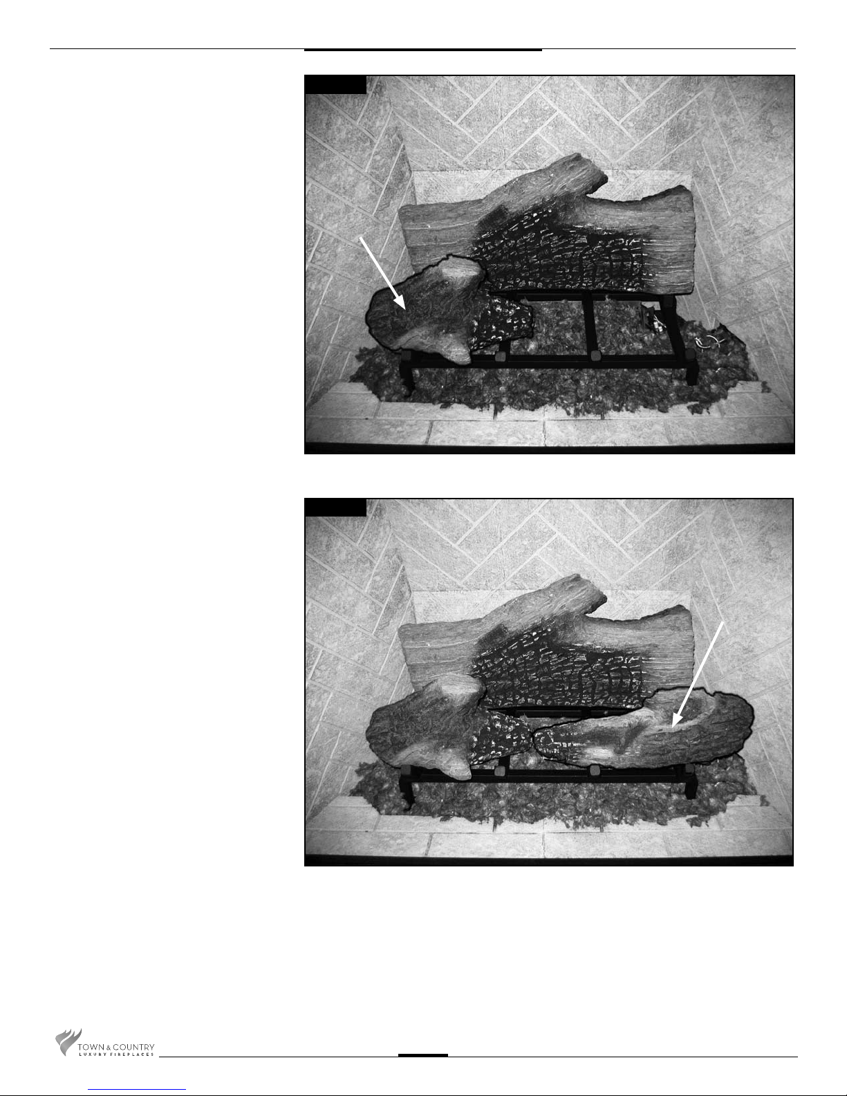
Fig. # 8
LOG #2
Fig. #9
LOG #3
TC30.NG06C 200411-16
6
Page 7
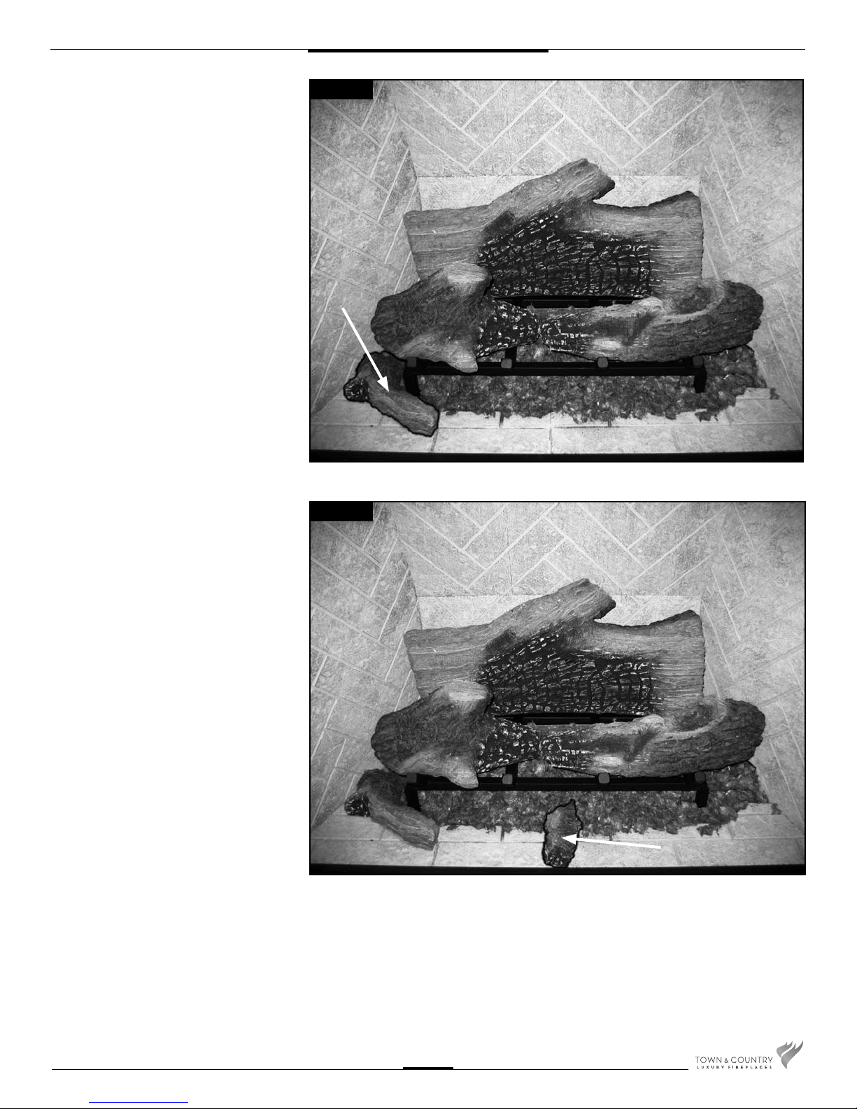
Fig. #10
LOG #4
Fig. #11
LOG #5
TC30.NG06C 200411-16
7
Page 8
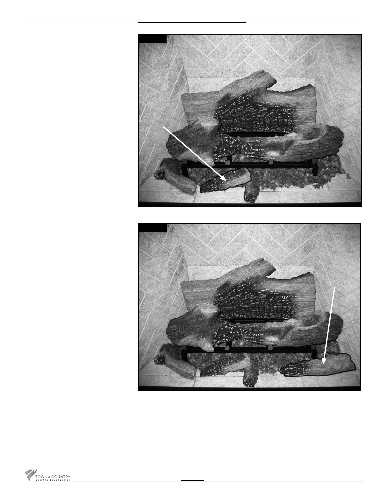
Fig. #12
LOG #6
Fig. #13
Note: Improper placement of logs will
cause sooting on internal parts and
glass.
LOG #7
TC30.NG06C 200411-16
8
Page 9
Propane Conversion
WARNING
This conversion kit
shall be installed by a
quali ed service agency
in accordance with the
manufacturer's instructions
and all applicable codes
and requirements of
the authority having
jurisdiction.
If the information in these
instructions is not followed
exactly, a re, explosion
or production of carbon
monoxide may result
causing property damage,
personal injury or loss of
life.
The quali ed service
agency is responsible for
the proper installation of
this kit.
The installation is not
proper and complete
until the operation of the
converted appliance is
checked as speci ed in the
manufacturer's instructions
supplied with the kit.
If the unit is to be used on propane
convert as follows using the
components supplied with this
burner:
For use with model:
Pour utilise avec du modèle:
Date: ______________________
By / Par: ___________________
LP GAS/
DU GAZ LP
12.5 in/wc /12.5 po/c.e.
(3.11 kPa)
13.9 in/wc / 13.9 po/c.e.
(3.45 kPa)
11.0 in/wc / 11.0 po/c.e.
(.95 kPa)
# 48 (1.93 mm)
Max.: 35,000 (10.3)
Min.: 27,000 (7.91)
CONVERSION LABEL (5052.52085)
TC30
Series C
This appliance was converted
to PROPANE GAS with this kit
on this date by the organization which accepts the responsibility that this conversion
has been properly made. / Cet
appariel etair converter au gaz
LP par l’emploi de la trousse
de conversion par une organization qui accepte la responsibilité pour une installation en
bon état.
080411 6-TC30 5052.52085
Note: Factory supplied components must be
used to ensure correct input.
After conversion con rm proper manifold
pressure.
1. Ensure the burner, pilot and gas
supply are turned off, and the
appliance has cooled.
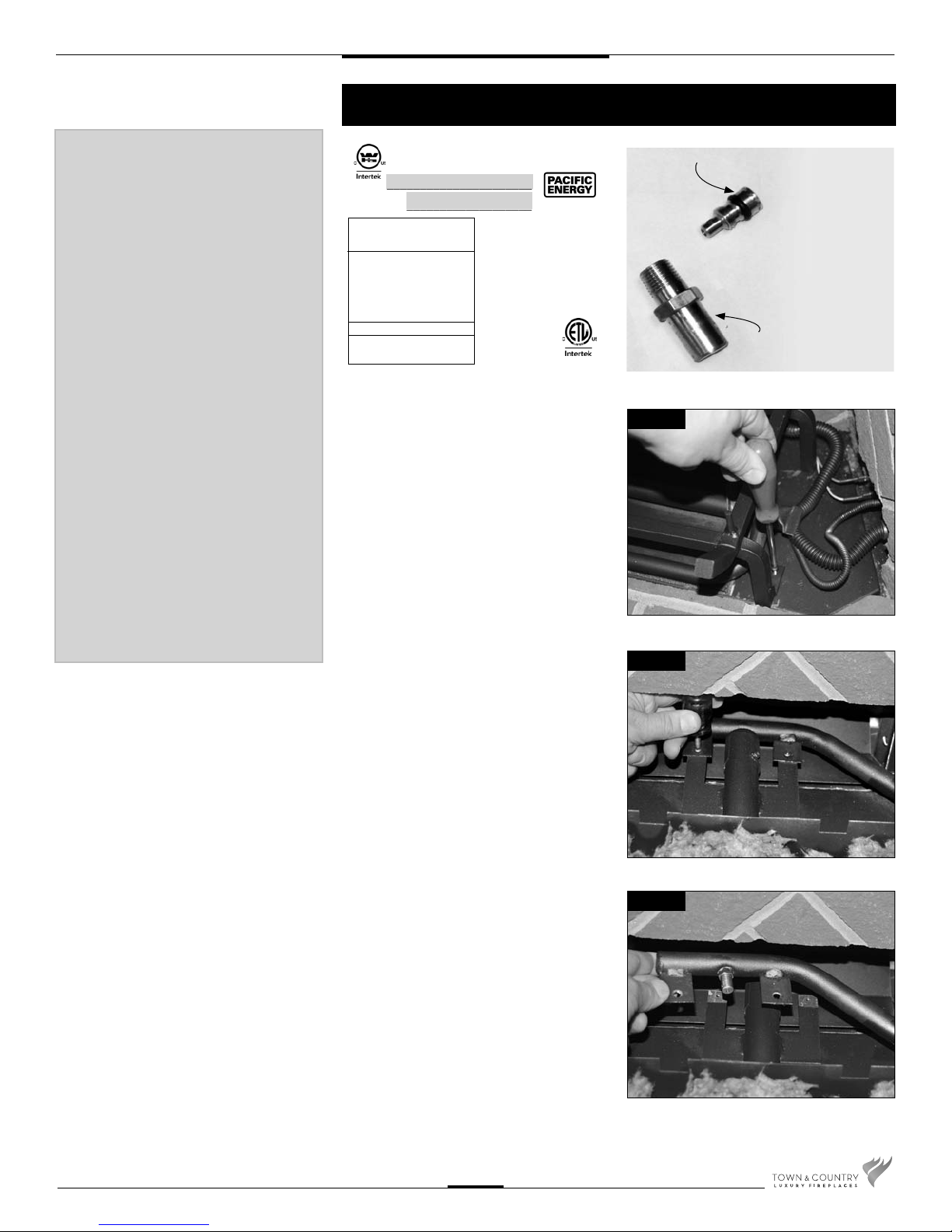
2. Remove the two screws securing the
the burner grate.
(Fig. #14)
3. Remove the two screws securing the
manifold assembly to the burner.
(Fig. #15)
MINIMUM RATE SCREW (5005.011)
MAIN BURNER
(#48) ORIFICE (5021.3407)
Fig #14
Fig #15
CAUTION
The gas supply and electrical power
shall be shut off before proceeding
with the conversion.
TC30.NG06C 200411-16
4. Remove the manifold assembly from the
Fig #16
burner. (Fig. #16)
9
Page 10
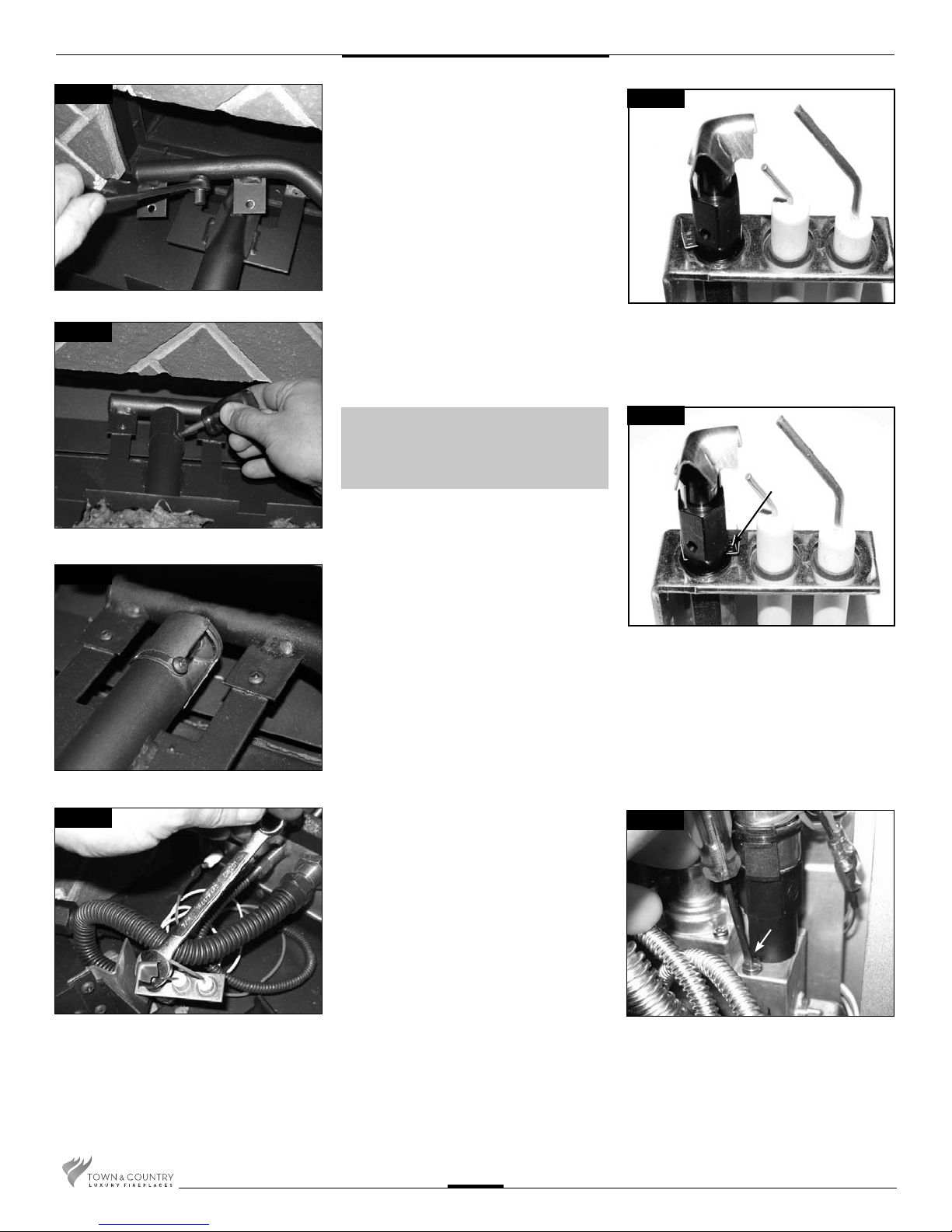
Fig #17
Fig #18
5. With a ½” wrench remove the natural gas
ori ce (#32) and replace with propane
ori ce (#48)(our part # 5021.3407)
(Fig. #17)
6. Fully open the primary air shutter.
7. Reinstall the manifold and air de ector
Fig #21
9. Slide the pilot adjustment band over and
ensure that the hole in the ori ce band
is showing. (Fig. #21 shows NG position,
Fig. # 22 shows LP position)
Retighten pilot head.
Fig #19
Fig #20
NOTE: Primary air shutter must
be fully closed for Natural gas or
fully open for Propane.
8. With a 7/16” wrench loosen the pilot head
on the pilot assembly by a half-turn
(Fig. #20)
Fig #22
HOLE
10. Remove right hand brick panel (if
installed) and access panel located on
right hand side of rebox
(See Fig. #27).
11. Remove the minimum rate screw located
in the valve.
(Fig. #23)
Fig #23
Minimum
rate screw
TC30.NG06C 200411-16
10
Page 11
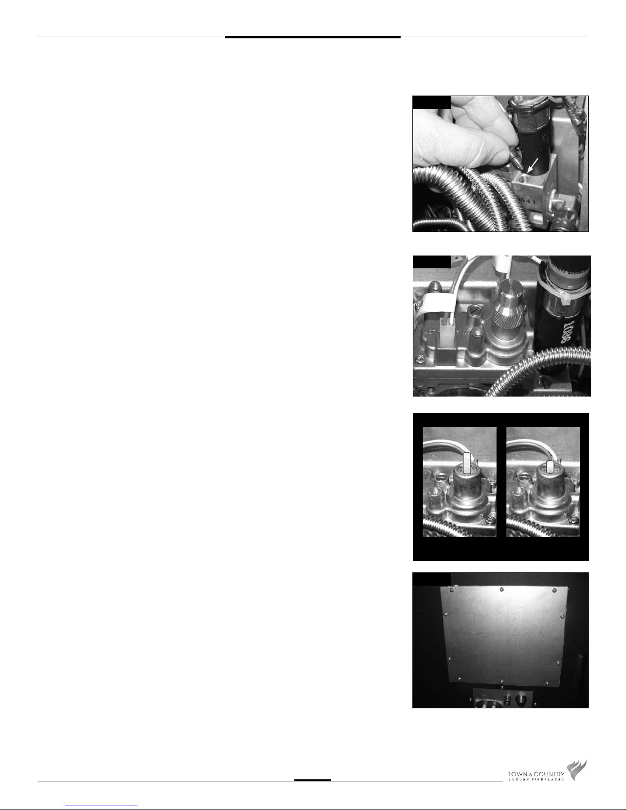
12. Replace the minimum rate screw with the
one provided in the propane conversion
kit supplied with this replace. Ensure
that the screw is fully installed.
(Fig. #24)
Fig #24
Minimum
rate screw
13. Remove the aluminum cap from the top
of the pressure regulator. (Fig. #25)
14. Press down on the center post and
rotate 90°. The center post should
stay down. (Fig. #26). Replace the
aluminum cap.
15. Fill in the date and the name of the
person who performed the conversion in
the white area on the conversion label.
Peel off the protective backing and apply
the conversion label directly over the
gas speci cations on the rating label.
Fig #25
Fig #26
NG
LP
TC30.NG06C 200411-16
16. Attach the access panel to the side of
the rebox with the previously removed
screws. (Fig. #27)
Note:
Gasket must be installed with access
panel.
11
Fig #27
Page 12
Gas Pressure Check
Note: To test the gas pressure, turn off the gas supply before removing the plug from
the supply pressure test port or manifold pressure test port.
Verify gas pressures with the replace lit and on the highest setting.
Fig #28
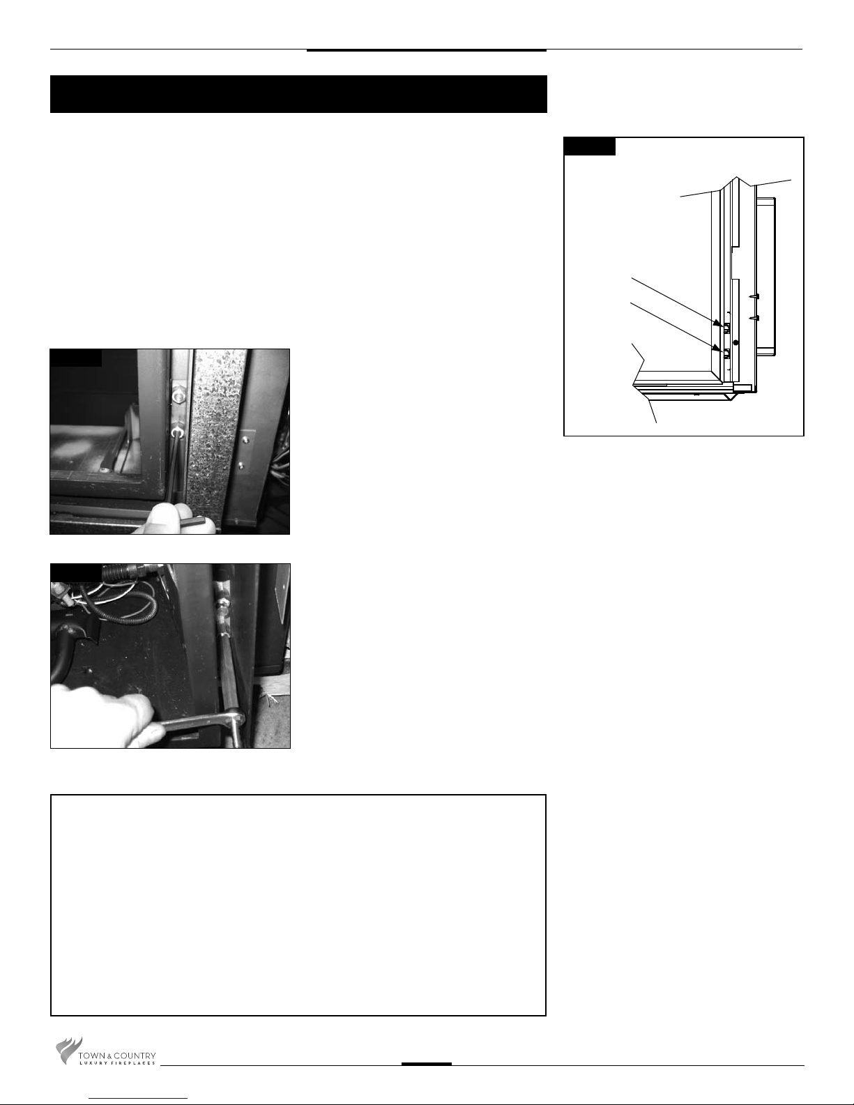
1. Remove the plug from the pressure
test port. The plug is located
between the right side lintel and
rebox side (bottom port). (Fig. #33)
Fig #29a
SUPPLY
PRESSURE
MANIFOLD
PRESSURE
Fig #28
2. Thread the extension test tting into the
open test port. (Fig. #34)
3. Attach a pressure gauge onto the
tting.
4. When testing is complete remove the
extension test tting and replace the
plug. Thread sealant will be required to
ensure a gas tight connection.
Correct gas pressure requirement:
Supply Pressure Natural Gas Propane
Min. Pressure 5.0" WC 12.5" WC
(For purpose of input adjustment)
Max. Pressure 13.9" WC 13.9" WC
Manifold Pressure
Maximum 3.8" WC 11" WC
Minimum 2.1" WC 5.5" WC
TC30.NG06C 200411-16
12
Page 13
Burner Flame Adjustment
The air shutter on the burner tube controls the primary combustion air to the gas burner
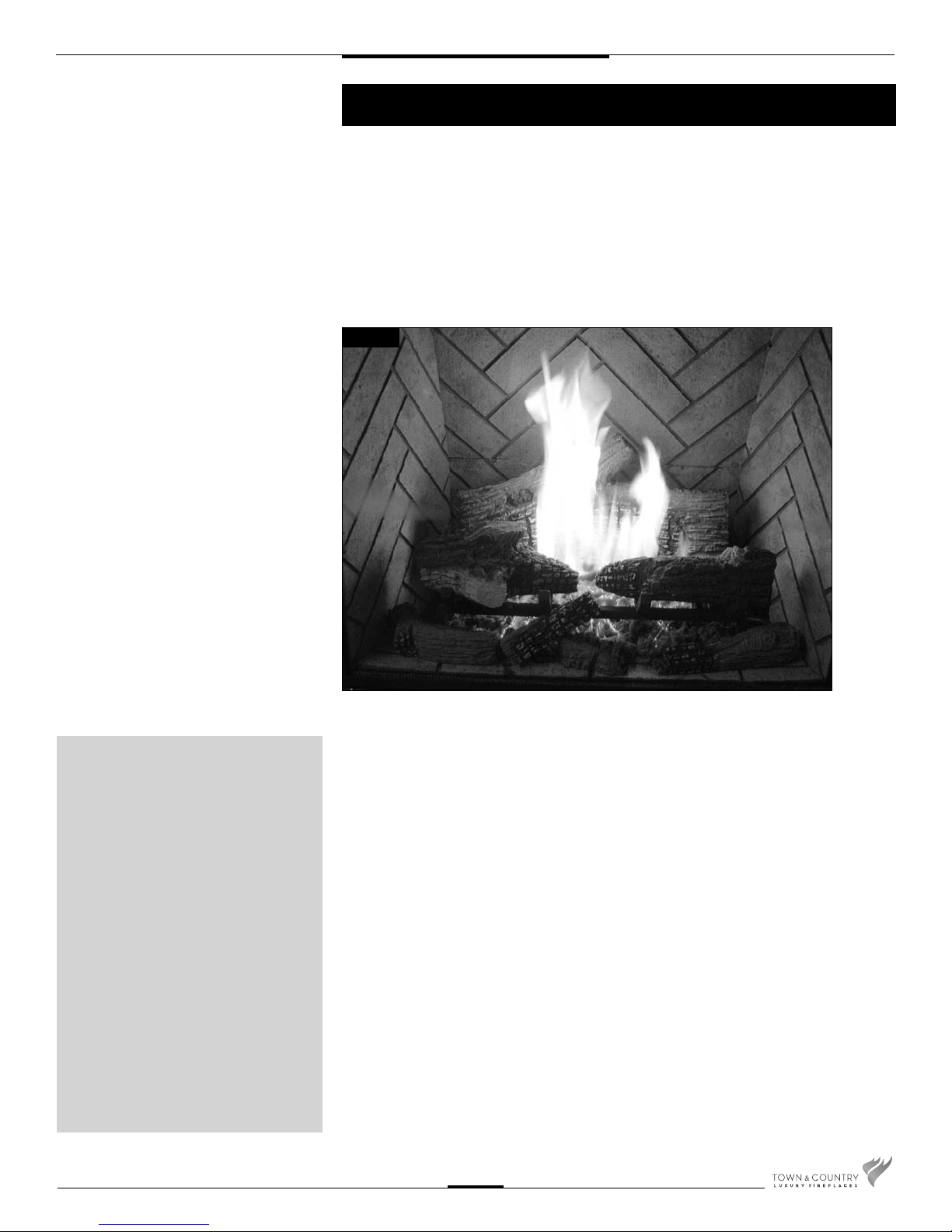
and is preset at the factory for natural gas fuel. Some adjustment may be necessary to
obtain desired ame and to eliminate carbon deposits. Evaluate ame appearance after
the replace has reached operating temperature. See Fig. #29 for proper ame pattern.
Open primary air shutter if the logs, glass, and rebox have carbon accumulation and/or
the ames are long, dark and stringy. The shutter may also be opened to enhance the
ember material glow and lessen the ame height.
Fig #29
Caution:
Proper air shutter setting is
a must.
The ame should be just orange
and “lazy”.
It should NEVER be set to
create sooting on internal parts
and glass.
TC30.NG06C 200411-16
Caution: Burner area may be hot!
Turn off the replace and allow the unit to cool before proceeding.
To Adjust:
1. Open and remove window frame and set aside. See “Window Frame Removal” section
found in the Installation and Operating Instructions manual.
2. Remove the logs and set aside.
3. Remove air de ector from log grate (2 screws)
4. Loosen the Primary Air Shutter screw.
5. Rotate the shutter to increase or decrease the amount of primary air.
6. Reassemble in reverse order.
13
Page 14
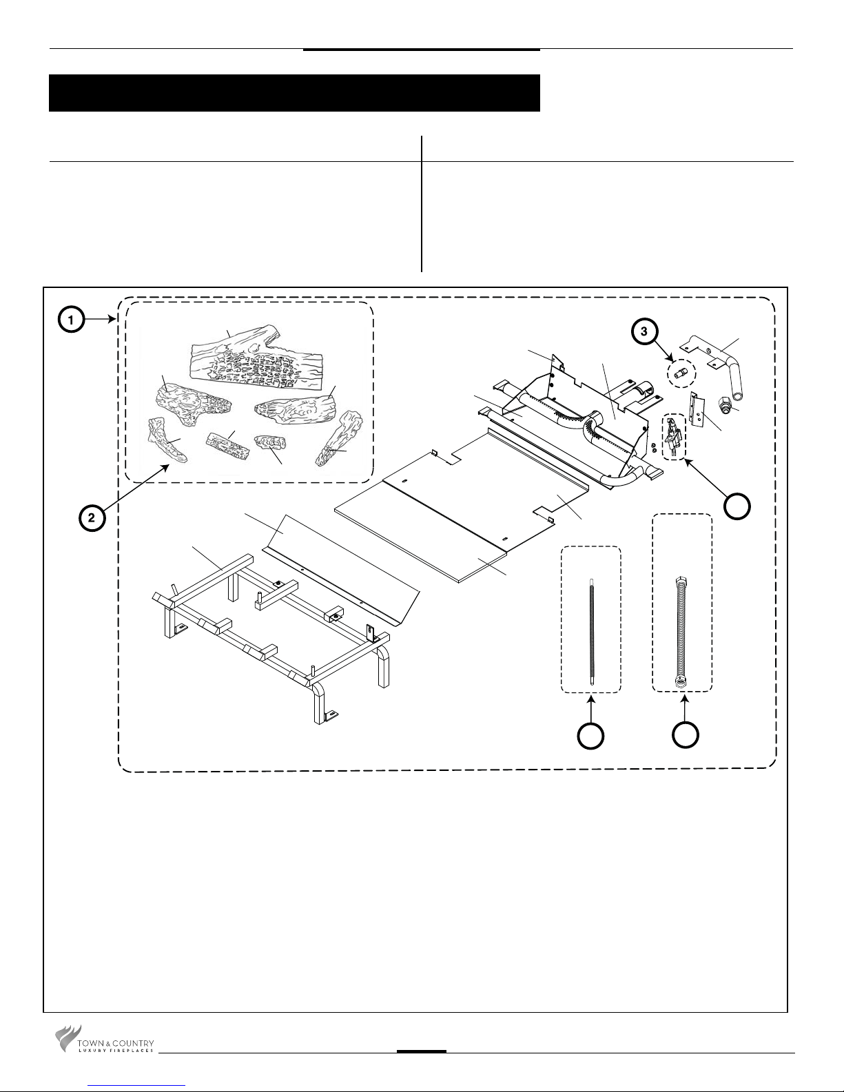
Replacement Parts
(WHEN ORDERING, INCLUDE PART NUMBER WITH DESCRIPTION)
ITEM .......DESCRIPTION ............................................PART NO.
ITEM .......DESCRIPTION ............................................PART NO.
#1..........CHALET II BURNER ASSEMBLY ...... TC30.NG06C
#2..........7 PCS LOG SET ................................. 5094.301795
#3..........ORIFICE, NATURAL GAS (#32) ......... 5021.332.A
2a
2b
1a
2e
2d
2f
1b
2c
2g
#4..........PILOT ASSEMBLY.....................TCRP.5005025
#5..........MAIN SUPPLY TUBE .......................... 5019.223
#6..........PILOT TUBE ...................................... 5019.225
#7..........PROPANE CONVERSION KIT ........... TC30.LPCE01
*
NOT SHOWN
*
1f
1g
1h
1c
1d
1e
4
1i
KIT CONTENTS:
#1.... BURNER ASSEMBLY
1a GRATE
1b
1c BURNER TRAY
1d PILOT SHIELD
1e BLOCKER PLATE
1f MANIFOLD
1g 1/2 PIPE TO 1/2 TUBE CONNECTION
1h PILOT BRACKET
1i HEAT SHIELD
1j HEAT SHIELD INSULATION
2a BASE LOG
2b TOP LEFT LOG
2c TOP RIGHT LOG
2d CENTER CHUNK
2e BOTTOM LHS CHUNK
AIR DEFLECTOR
2f BOTTOM CENTER CHUNK
2g BOTTOM RHS CHUNK
3 ORIFICE, NATURAL GAS
4 PILOT ASSEMBLY
5 MAIN SUPPLY TUBE
6 PILOT TUBE
#2.... 7 PCS LOG SET
2a BASE LOG
2b TOP LEFT LOG
2c TOP RIGHT LOG
2d CENTER CHUNK
2e BOTTOM LHS CHUNK
2f BOTTOM CENTER CHUNK
2g BOTTOM RHS CHUNK
1j
6
#3.... ORIFICE, NATURAL GAS (#32)
#4.... PILOT ASSEMBLY, CONVERTIBLE
#5.... MAIN SUPPLY TUBE
#6.... PILOT TUBE
#7.... PROPANE CONVERSION KIT (Not shown)
5
TC30.NG06C 200411-16
14
Page 15

TC30.NG06C 200411-16
15
Page 16

Technical support: 1-250-748-1184
Web site: www.townandcountry replaces.net
2975 Allenby Rd., Duncan, BC V9L 6V8
Printed in Canada
 Loading...