

Page 1
EN
Technical specifications 2ch alarm output expander kit
Communication bus type
TBS QuickLink
Current consumption
< 1mA
Relay A and B contact ratings
8A / 250Vac or 8A / 30Vdc
Relay A and B dielectric strength
4000Vac (1min.) between coil and contacts
Relay pulse time (contactor mode)
approx. 750ms
Operating ambient temp.
-20 ... +50 °C
Dimensions (L x W x H)
100 x 100 x 24mm
Technische specificaties ‘2ch alarm output expander kit’
Communicatiebus type
TBS QuickLink
Stroomverbruik
< 1mA
Relais A en B contact specificaties
8A / 250Vac of 8A / 30Vdc
Relais A en B isolatiespanning
4000Vac (1min.) tussen spoel en contacten
Relais pulstijd (contactor modus)
ca. 750ms
Omgevingstemperatuur
-20 ... +50 °C
Afmetingen (L x B x H)
100 x 100 x 24mm
QuickLink 2ch Alarm Output Expander Kit (#5093120) installation guide
NL
1
Relay box
Relaiskastje
2
3
Battery monitor
Batterij monitor
QuickLink 2ch Alarm Output Expander Kit (#5093120) installatie voorschriften
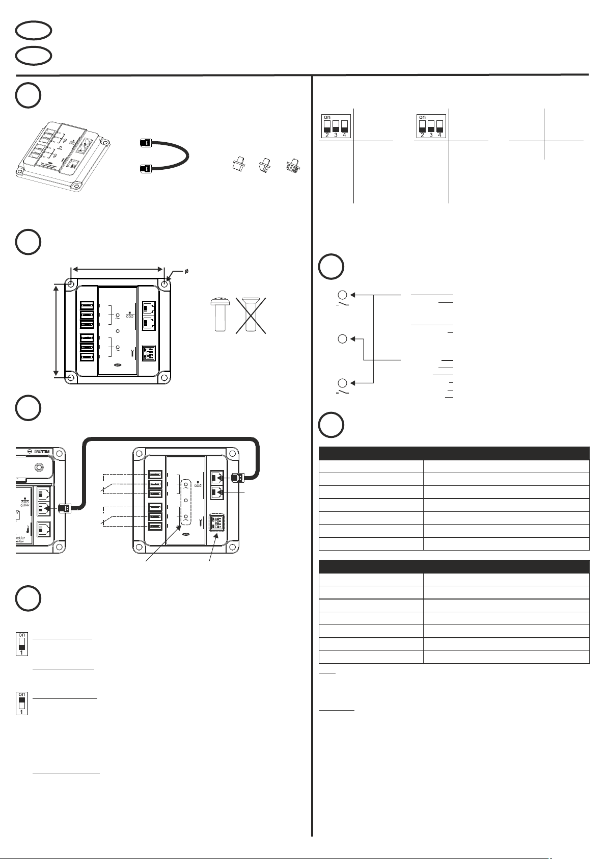
Package contents
Inhoud verpakking
DIP switches 2, 3 and 4 (relay addressing)
DIP switches 2, 3 en 4 (relais adressering)
DIP switch Relay / Relais
DIP switch Relay / Relais
A B
off
QuickLink cable
QuickLink kabel
Mounting the relay box
Monteren van het relaiskastje
88mm
NO
COM
QLINK
A
NC
status
88mm
NO
COM
NC
two channel alarm
output expander
B
Connecting the relay box
Aansluiten van het relaiskastje
Faston RJ12 DIP switch
x4 x1 x1
Rubber covers
Rubber afdekkapjes
5mm
Do not use mounting screws with
countersunk heads.
Gebruik geen montage schroeven met
verzonken kop.
off off E XT.1 EXT.2
off off on EX T.2 EXT.3
off on off EX T.3 EXT.4
off on on E XT.4 EXT.5
on off off EXT.5 EXT.6
on off on E XT.6 EXT.7
on on off E XT.7 EXT.8
on on on EXT.8 EXT.9
Table 1 (normal operating mode)
Tabel 1 (normale werkingsmodus)
LED indications
5
LED indicaties
A
status
B
Specifications plus notes
6
Specificaties en opmerkingen
off
off off EXT.1
off off on EXT.2
off on off EXT.3
off on on EXT.4
on off off EXT.5
on off on EXT.6
on on off EXT.7
on on on EX T.8
Table 2 (contactor mode)
Tabel 2 (contactor modus)
off
flashing green
In contactor mode, A and B will flash simultaneously when an alarm
is acve
uit
knipperend groen
In contactor modus, knipperen A en B tegelijkerjd wanneer er een
alarm acef is
flashing orange
flashing green
flashing red
Knipperend oranje
Knipperend groen
Knipperend rood
Contactor
configuraon
A+B
relay not activated
relay activated
relais niet geactiveerd
relais geactiveerd
waiting for QuickLink connection
normal operation / data indicator
QuickLink communication error
wachten op QuickLink verbinding
normaal bedrijf / data indicator
QuickLink communicatie fout
Contactor
configurae
NO Set Reset
NC Reset Set
Table 3 (contactor configuration)
Tabel 3 (contactor configuratie)
Set = Close contactor
Reset = Open contactor
Set = Sluit contactor
Reset = Open contactor
Set and Reset pulse times are
approx. 750ms
Set en Reset pulstijden zijn ca.
750ms.
Relay / Relais
A B
Relay outputs
Relais uitgangen
A
B
For details see step 5
Voor details zie stap 5
NO
COM
QLINK
A
NC
status
NO
COM
B
NC
two channel alarm
output expander
For details see step 4
Voor details zie stap 4
Additional QLI NK port
for connecting other
QuickLink accessories
(see notes in step 6 for
additional information)
Extra QLI NK poort voor
het aansluiten van
andere QuickLink
accessoires (zie
opmerkingen bij stap 6
voor aanvullende
informatie)
DIP switch settings
4
DIP switch 1 (operating mode) / DI P switch 1 (werkingsmodus)
DIP switch instellingen
Normal operating mode. The alarm expander relays A and B are operating independently and can be
controlled from the QuickLink master (i.e. battery monitor) by linking an alarm condition to EXT.1, EXT.2 etc.,
depending on alarm expander address (see table 1 in next column).
Normale werkingsmodus. De ‘alarm expander’ relais A en B werken onafhankelijk van elkaar en kunnen
bestuurd worden vanuit de QuickLink master (bv. batterij monitor) door een alarm conditie toe te wijzen aan
EXT.1, EXT.2 etc., afhankelijk van het ‘alarm expander’ adres (zie tabel 1 in volgende kolom).
Contactor mode (latching). The alarm expander relays A and B are combined in order to control the ‘open
(reset)’ and ‘close (set)’ coils from a dual coil magnetically latching contactor. Which relay contact to use for
controlling the contactor coils, depends on whether the contactor needs to operate in a Normally Open (NO)
or Normally Closed (NC) configuration. For example, when an alarm requires a load to be disconnected from a
battery, the contactor needs to operate in an NC configuration. However, when an alarm requires a source to
be connected to a battery, the contactor needs to operate in an NO configuration. Table 3 shows the relay
command types depending on the desired contactor configuration. When an alarm is activated, relay A will be
operated. When an alarm is deactivated, relay B will be operated. In contactor mode, the alarm expander can
only control one external contactor. See table 2 for more details.
Contactor modus (latching). De ‘alarm expander’ relais A en B zijn gecombineerd voor het besturen van de
‘open (reset)’ en ‘sluit (set)’ spoelen van een ‘latching contactor’. Welk relais te gebruiken voor deze spoelen is
afhankelijk van de wens om de contactor in een ‘Normally Open (NO)’ of een ‘Normally Closed (NC)’
configuratie te gebruiken. Wanneer een alarm bijvoorbeeld vereist dat een belasting wordt afgekoppeld van
een accu, moet de contactor in een ‘NC‘ configuratie opereren. Maar wanneer een alarm vereist dat er een
bron moet worden aangesloten op een accu, moet de contactor in een ‘NO’ configuratie opereren. In tabel 3
staan de relais functies getoond voor beide contactor configuraties. Wanneer een alarm activeert, wordt relais
A gestuurd. Wanneer een alarm de-activeert, wordt relais B gestuurd. In contactor modus kan de ‘alarm
expander’ maximaal één contactor aansturen. Zie tabel 2 voor meer informatie.
Notes:
1. Each QuickLink network may contain only one master device (i.e. battery monitor)
2. Each QuickLink network may contain a maximum of four alarm expanders
Opmerkingen:
1. Elk QuickLink netwerk mag maar één master unit (bv. batterij monitor) bevatten
2. Elk QuickLink netwerk mag maximaal vier ‘alarm output expanders’ bevatten
TBS QuickLink to 2ch Alarm Output Expander Kit Installation Guide rev1en
 Loading...