

Page 1
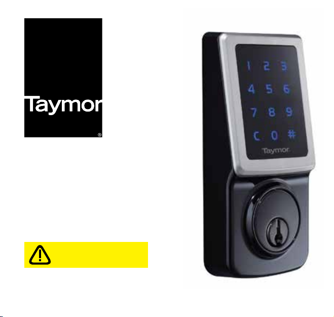
CONCIERGE 400
PROFESSIONAL SERIES
ELECTRONIC DEADBOLT
IMPORTANT: Before first use,
please read page 1 9 in the User
Guide for important instructions.
USER GUIDE
06/2016
Page 2

® REGISTERED TRADEMARK OF TAYMOR INDUSTRIES LTD.
Page 3

CONTENTS
IMPORTANT SAFETY INFORMATION 1
TOOLS NEEDED FOR NEW INSTALLATION 2
COMPONENTS OF ELECTRONIC KEYPAD DEADBOLT 3
DOOR PREPARATION 4 - 8
INSTALLATION 9 - 19
OVERVIEW OF FUNCTIONS 20
CODES INFORMATION 21
PROGRAMMING
1. CHANGE PROGRAMMING CODE 22
2. ADD NEW USER ENTRY CODE OR SINGLE ENTRY CODE 23
3. ENABLE/DISABLE THE GUIDING CODE 24
4. DELETE USER ENTRY CODES 25
5. ENABLE/DISABLE VACATION MODE 26
6. VOLUME CONTROL 27
7. SET UP AUTO-LOCK TIME DELAY 28
8. ENABLE/DISABLE AUTO-LOCK FUNCTION 29
9. RESTORE FACTORY SETTING 30
OPERATION
1. HOW TO LOCK/UNLOCK THE LOCKSET 31
2. SECURITY MODE 32
TROUBLESHOOTING GUIDE 33 - 38
INFORMATION PAGE 39
WARRANTY 40
Page 4

IMPORTANT SAFETY INFORMATION
!
WARNING
1. Do not use any abrasives or any chemical products containing any substance
of alcohol, benzene, hydrochloric acid or nitric acid, and avoid sharp or
scratching objects to clean this lockset.
2. Do not let any water or liquid into lockset during installation process.
Note: Electronic mechanisms may be sensitive in cold, harsh conditions particularly
if the environment is also humid. In these conditions, the manual key may be the
most convenient method to operate the lock.
!
IMPORTANT SAFETY INSTRUCTION
1. Do not attempt to disassemble any internal components of the lockset
personally. You may run the risk of voiding the limited warranty.
2. Do not drop or hit the lockset.
3. Do not use sharp objects to press key buttons.
4. Always create a backup of information you want to keep (such as programming
code and user entry codes). Please use the last page of this booklet as your
reference.
5. Please change the programming code before operating this lockset.
!
CARE AND MAINTENANCE
The following care instructions should be followed:
1. Remove locks, or do not install locks, prior to painting your door.
2. Periodically clean with mild soap and a soft cloth only.
3. Do not use any abrasives or chemical products containing alcohol, benzene,
hydrochloric acid or nitric acid, and avoid using sharp or abrasive objects to
clean this lockset.
4. Do not let any water or liquid into lockset during installation and care processes.
1
® REGISTERED TRADEMARK OF TAYMOR INDUSTRIES LTD.
Page 5
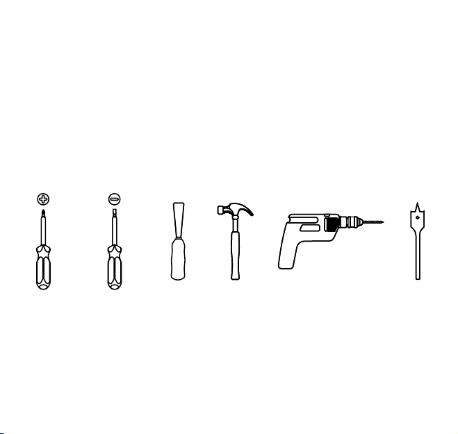
TOOLS NEEDED FOR NEW INSTALLATION
• PHILLIPS SCREWDRIVER
• FLAT HEAD SCREWDRIVER
• CHISEL
• HAMMER
• 1” (25.4 mm) and 2 -1/8” (54 mm) OR 1-1/2” (38 mm) HOLE BORING KIT
• POWER DRILL
• 4 - AA ALKALINE BATTERIES
OPTIONAL OPTIONAL OPTIONAL OPTIONAL OPTIONAL
® REGISTERED TRADEMARK OF TAYMOR INDUSTRIES LTD.
2
Page 6
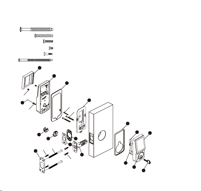
COMPONENTS OF ELECTRONIC
KEYPAD DEADBOLT
AA. 2-1/8” Mounting Bolt
BB. 1-1/4” Screw
CC. 13/16” Screw
DD. 5/16” Screw
EE. 3/4” Wood Screw
FF. 3” Wood Screw
J
I
H
DD
Q
CC
O
N
EE
P
3
® REGISTERED TRADEMARK OF TAYMOR INDUSTRIES LTD.
BB
AA
L
FF
M
EE
G
K
QTY.
A. Key (2)
B. Exterior Assembly
C. Cylinder
D. Tailpiece
2
E. Power Cable
1
F. Exterior Gasket (Optional)
1
G. Mounting Plate
2
H. Interior Gasket (Optional)
4
I. Interior Assembly
J. Battery Cover
2
K. Latch
L. Bottom Plate (Optional)
M. Square or Radius Faceplate
(Optional)
N. Drive-In Collar (not assembled)
O. Drive-In Collar (assembled)
P. High Security Strike Plate
Q. Screw Hole Cover
F
E
B
D
C
A
Page 7
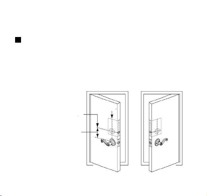
DOOR PREPARATION
1
MARK DOOR WITH TEMPLATE (ATTACHED SEPARATELY)
Note: If replacing an existing lock or installing in a pre-drilled door,
begin with page 9.
a. Use TEMPLATE to mark centerline on door for deadbolt about
3” to 6” (75 mm to 150 mm) above the existing knob or lever.
b. Stand so door swings towards you. Align template on centerline
and fold template as shown.
CENTERLINE
MARK DOOR EDGE APPROXIMATELY
3” TO 6” (75 mm TO 150 mm) ABOVE
THE ENTRY KNOB OR LEVER
TEMPLATE
® REGISTERED TRADEMARK OF TAYMOR INDUSTRIES LTD.
4
Page 8
DOOR PREPARATION
2
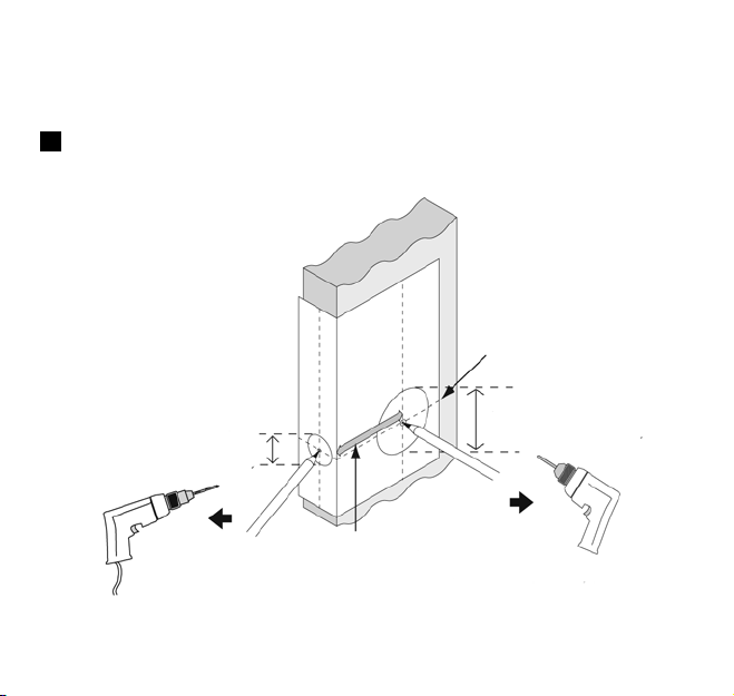
MARK AND DRILL PILOT HOLES
Select backset. Mark and drill pilot holes as shown.
CENTERLINE
2-1/8” OR 1-1/2”
1”
(25 mm)
DRILL 1/8” (3 mm) PILOT HOLE
5
® REGISTERED TRADEMARK OF TAYMOR INDUSTRIES LTD.
BACKSET
(54 mm) (38 mm)
DRILL 1/8” (3 mm) PILOT HOLE
Page 9
DOOR PREPARATION
3.1
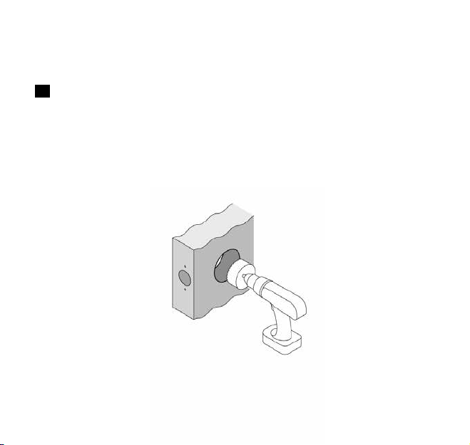
DRILL HOLES
a. Drill a 2-1/8” (54 mm) hole on the door face from both sides to
avoid wood splitting.
b. Use a 2” (51 mm) 6d common nail and press it from inside the
2-1/8” (54 mm) or 1-1/2” (38 mm) hole through the pilot hole to
mark centerlines on jamb exactly opposite center of deadbolt
latch hole.
2-1/8”
(54 mm)
® REGISTERED TRADEMARK OF TAYMOR INDUSTRIES LTD.
6
Page 10
DOOR PREPARATION
3.2
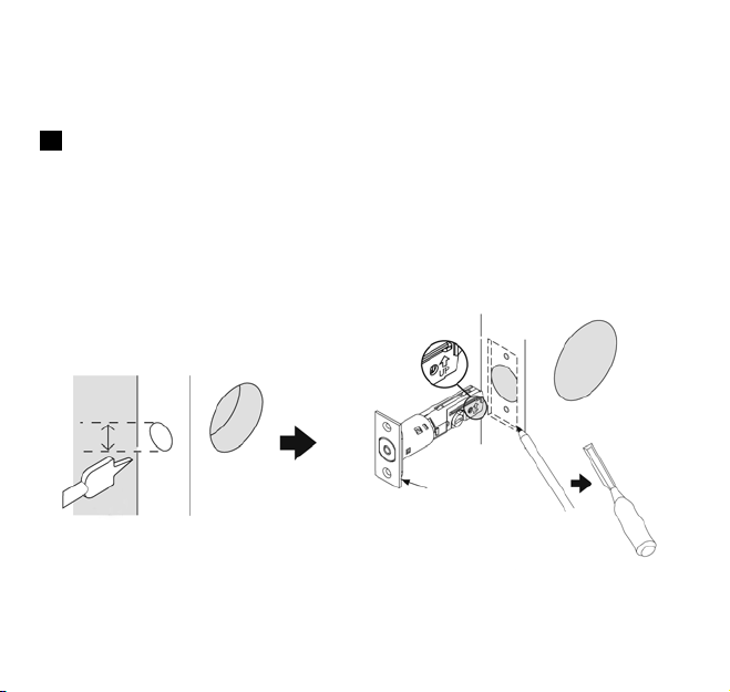
DRILL HOLES
c. Drill a 1” (25 mm) hole in the door edge for the latch.
d. Use faceplate as a pattern for mortise and pilot holes.
Chisel 5/32” (4 mm) deep. Faceplate should fit flush.
Note: For drive-in latch, simply insert latch.
e. Install as shown for appropriate latch type. Ensure bevel
faces door jamb.
1”
(25 mm)
c.
7
® REGISTERED TRADEMARK OF TAYMOR INDUSTRIES LTD.
FACEPLATE
d.
OUTLINE
CHISEL 5/32”
(4 mm) DEEP
Page 11

DOOR JAMB PREPARATION
4
PREPARE DOOR JAMB AND INSTALL STRIKE PLATE
Door Jamb hole dimensions
a. 3/32” (2.5 mm)
b. 1” (25 mm)
c. 1-1/8” (28 mm)
HIGH SECURITY
STRIKE PLATE
3/4” (19 mm) SCREWS
3”(76 mm) SCREWS
b.
c.
a.
® REGISTERED TRADEMARK OF TAYMOR INDUSTRIES LTD.
8
Page 12
INSTALLATION
1a
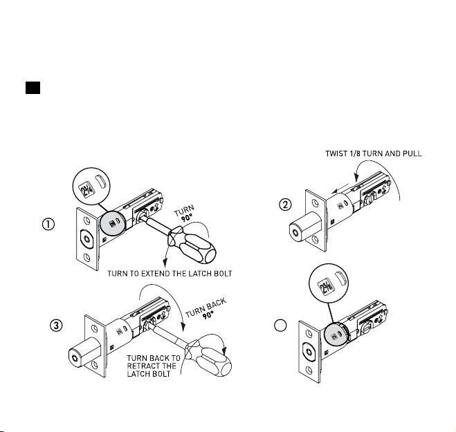
LATCH BACKSET ADJUSTMENT
Latch backset adjustment only needs to be made if your door needs
a 2-3/8” (60 mm) backset. Please follow diagrams below as reference.
Skip this if your door has a 2-3/4” (70 mm) backset
4
9
® REGISTERED TRADEMARK OF TAYMOR INDUSTRIES LTD.
Page 13
INSTALLATION
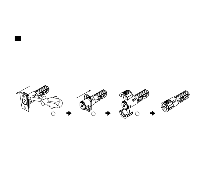
1b
DRIVE-IN COLLAR or FACEPLATE ADJUSTMENT
In addition to 2-3/8” (60 mm) or 2-3/4” (70 mm) adjustable backset,
you may change the faceplate to drive-in collar. (If your door is not
a drive-in latch type, please skip this step)
REM
OVE
1 2 3
REM
OVE
Note: Reverse the above steps if you need to change
the drive-in collar to the faceplate.
® REGISTERED TRADEMARK OF TAYMOR INDUSTRIES LTD.
COMBINE
10
Page 14
INSTALLATION
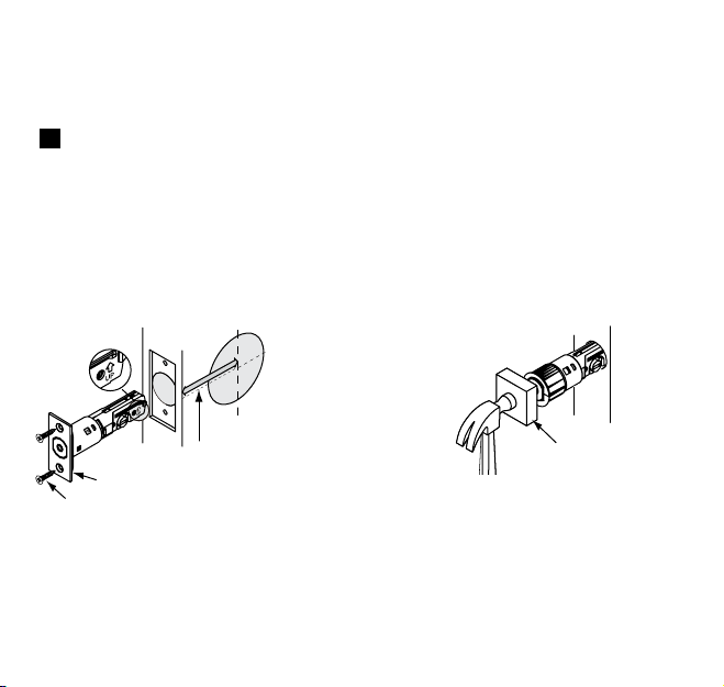
2
INSTALL LATCH IN MORTISED AREA OR INSTALL DRIVE-IN LATCH
If the backset of your door is 2-3/8” (60 mm), please install it now.
If your door is set up to use a standard type latch, please install it
with the 3/4” (20 mm) screws that are provided. If you use the
drive-in type latch, please tap it in place.
BACKSET
FACEPLATE
3/4” (20 mm) WOOD SCREWS
11
® REGISTERED TRADEMARK OF TAYMOR INDUSTRIES LTD.
OR
DRIVE-IN LATCH
WOOD BLOCK
(NOT INCLUDED)
(SEE PAGE 10 BEFORE
INSTALLATION OF
DRIVE-IN LATCH)
TAP
LATCH
FLUSH
Page 15
INSTALLATION
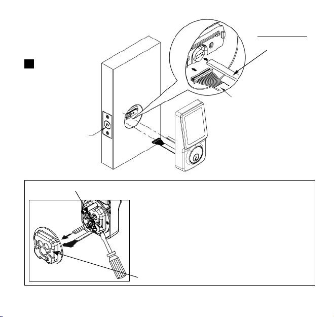
3
THE LATCH
BOLT SHOULD
BE IN THE
UNLOCKED
POSITION
IMPORTANT
INSERT
CYLINDER
TORQUE BLADE
IN HORIZONTAL
POSITION
THREAD THE CABLE
THROUGH THE HOLE AND
UNDER THE LATCH
CYLINDER MOUNTING SCREW
FOR INSTALLATION INTO 1-1/2” (38 mm)
BORE HOLE:
1. Remove adapter collar by releasing
cylinder mounting screw and top
mounting post.
2. Once adapter collar is off, reinstall
cylinder mounting screw.
ADAPTER COLLAR
® REGISTERED TRADEMARK OF TAYMOR INDUSTRIES LTD.
12
Page 16
INSTALLATION
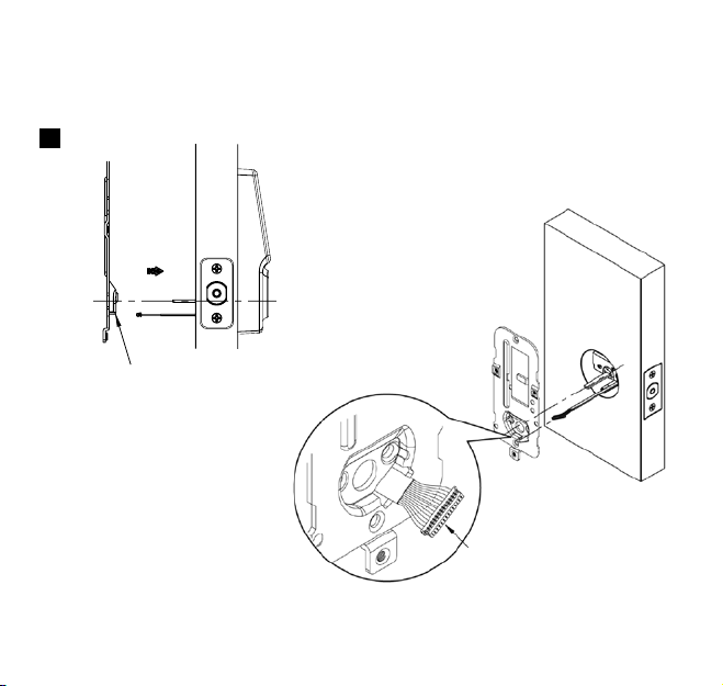
4
THE BULGED PART OF THE MOUNTING
PLATE MUST FACE TOWARD THE DOOR
13
® REGISTERED TRADEMARK OF TAYMOR INDUSTRIES LTD.
SLIDE CABLE THROUGH THE
NOTCH OF THE MOUNTING PLATE
Page 17
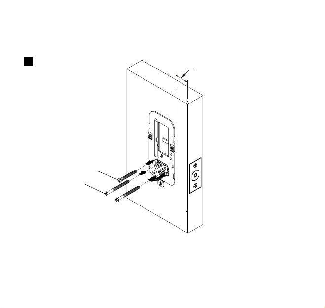
INSTALLATION
5
BB
AA
KEEP PARALLEL TO THE
EDGE OF DOOR
SECURE MOUNTING PLATE WITH 1-1/4” SCREW (1) AND 2-1/8” MOUNTING SCREWS (2)
(1-1/4” SCREW NOT REQUIRED FOR 1-1/2” BORE HOLE)
® REGISTERED TRADEMARK OF TAYMOR INDUSTRIES LTD.
14
Page 18
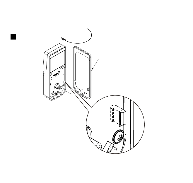
INSTALLATION
6
REMOVE THE INTERIOR COVER BY PUSHING THE THUMBTURN
THROUGH
INTERIOR GASKET (OPTIONAL)
15
® REGISTERED TRADEMARK OF TAYMOR INDUSTRIES LTD.
Page 19
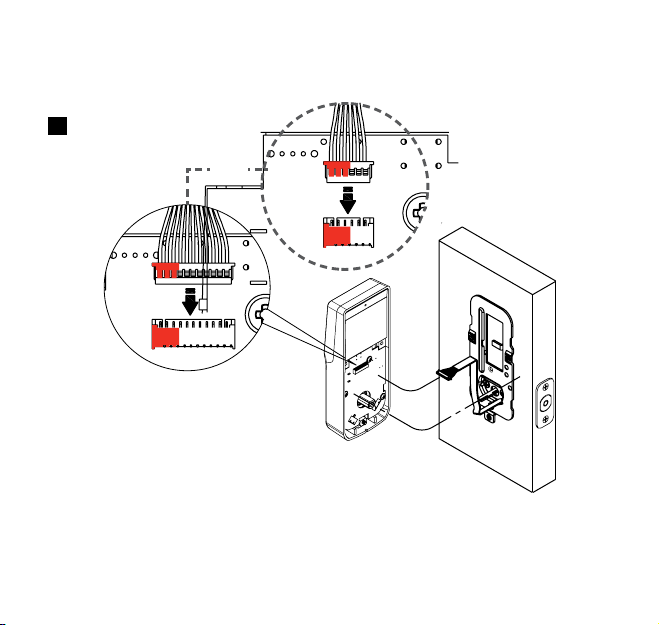
INSTALLATION
7
OR
CONNECT THE CABLE INTO
CONNECTOR PORT FIRMLY
® REGISTERED TRADEMARK OF TAYMOR INDUSTRIES LTD.
16
Page 20
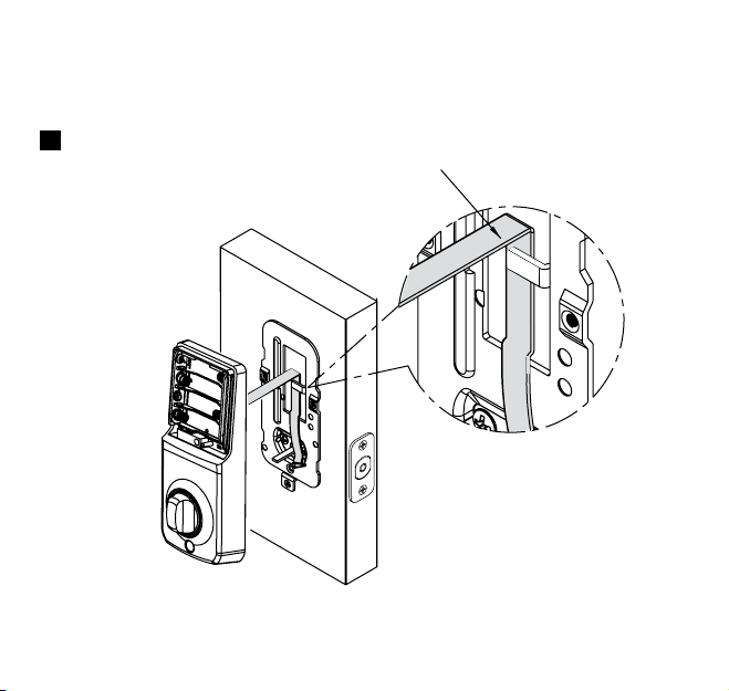
INSTALLATION
8
17
® REGISTERED TRADEMARK OF TAYMOR INDUSTRIES LTD.
THE CABLE MUST BE ARRANGED
AS SHOWN IN THE DIAGRAM
Page 21
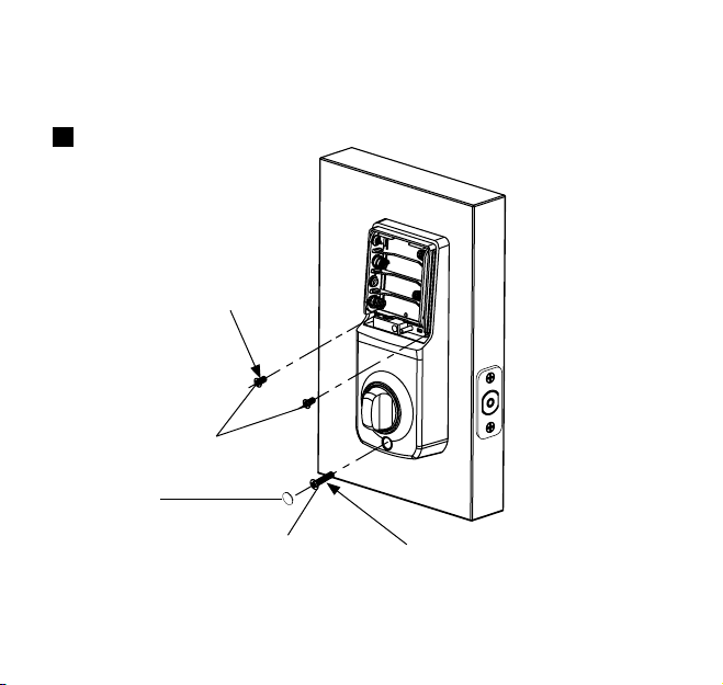
INSTALLATION
9
DD
INSERT 5/16” (8 mm)
SCREW (2) AND TIGHTEN
SCREW HOLE
COVER
INSERT 13/16” (20 mm)
SCREW (1) AND TIGHTEN
CC
® REGISTERED TRADEMARK OF TAYMOR INDUSTRIES LTD.
18
Page 22
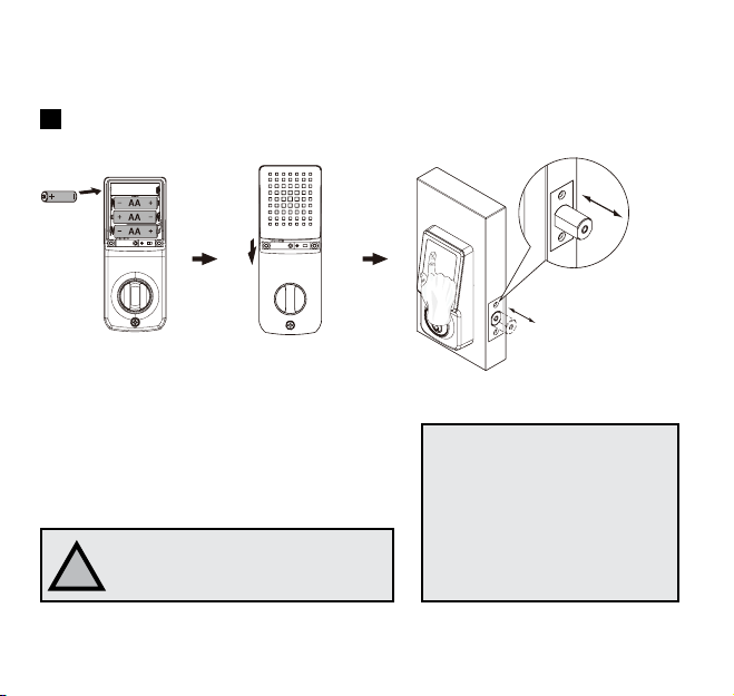
INSTALLATION
10
Install batteries and perform automatic bolt direction determination.
AA
Enter default program-
Install batteries
Install battery cover
CAUTION
Please use four alkaline batteries
!
for better performance.
19
® REGISTERED TRADEMARK OF TAYMOR INDUSTRIES LTD.
NOTE:
1. The lockset will perform
2. The product is ready for
ming code (12345678)
and the lock will set up
bolt direction to complete
installation.
automatic bolt direction
determination.
use when automatic bolt
direction determination is
completed.
Page 23
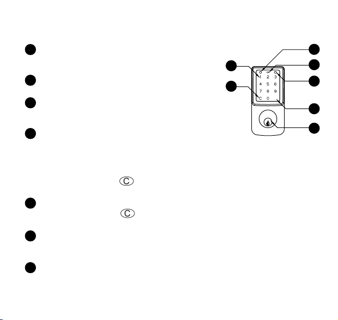
OVERVIEW OF FUNCTIONS
RED INDICATOR
1
1. Represents an incorrect entry or caution
by flashing red light.
2
LOW BATTERY INDICATOR
1. Flashes when the batteries are low in power.
3
GREEN INDICATOR
1. Represents a correct entry or positive response
by flashing green light.
4
TOUCH SCREEN
1. Touch to activate or lock.
2. Unlocks the lockset by entering a valid user code.
3. Programs the lockset by entering a valid
programming code.
4. Please always press button to cancel any typo
or exit the programming mode.
5
CLEAR BUTTON
1. Please always press button to cancel any typo
or exit the programming mode.
# BUTTON
6
1. Represents “enter” when in programming mode.
MECHANICAL KEYWAY OVERRIDE
1. To unlock the lockset by a valid key.
7
FUNCTIONS CONTINUED ON NEXT PAGE
® REGISTERED TRADEMARK OF TAYMOR INDUSTRIES LTD.
1
4
5
#
2
3
6
7
20
Page 24
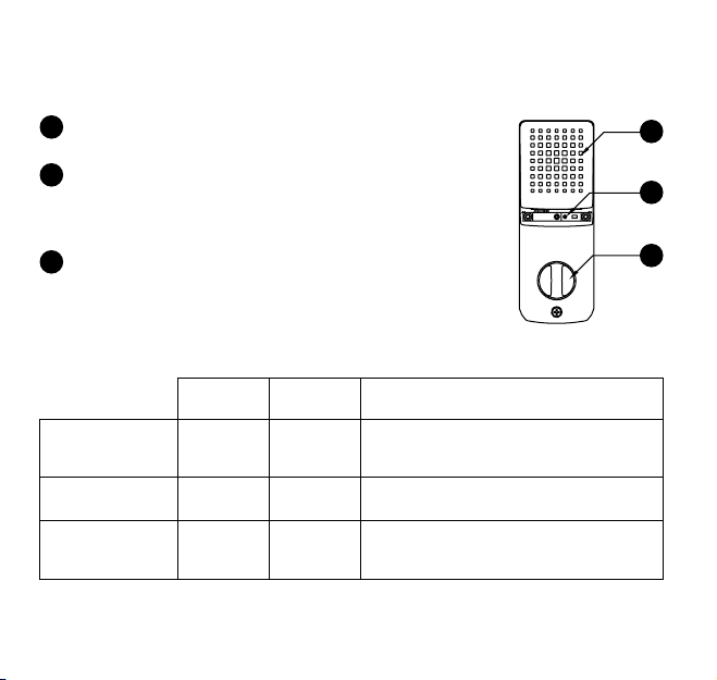
OVERVIEW OF FUNCTIONS continued
BATTERY COVER
8
1. Protects the batteries from unexpected damage.
SET BUTTON
9
1. Press set button for 1 second then enter correct
programming code to start programming the
lockset. See page 23.
INTERIOR THUMBTURN
10
1. Locks or unlocks the lockset manually.
8
9
10
CODE
LENGTH
Programming Code:
User Code:
Single-entry Code:
21
® REGISTERED TRADEMARK OF TAYMOR INDUSTRIES LTD.
4 - 8 digits 1 set
4 - 8 digits 25 sets
4 digits 4 sets
CODE
CAPACITY
REMARK
1. A programming code can be used to program
or unlock the lockset.
2. The default programming code is “12345678”.
A user code is set up by the programming code
and can be used to unlock the lockset.
A single entry code is set up by the programming
code and can only be used once to unlock the
lockset.
Page 25
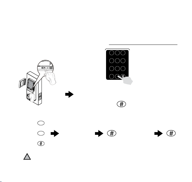
PROGRAMMING
CHANGING PROGRAMMING CODE
A programming code can be used to program or unlock the lockset.
The factory preset Programming Code is 1-2-3-4-5-6-7-8 and needs to
be changed to a unique 4-8 digit number before operating the deadbolt.
FUNCTION CODE [ 10 ]
STEP 1
Enter preset programming
code 1-2-3-4-5-6-7-8 or current
1 2 3
4 5 6
7 8 9
c
0
programming code
+
Press (SET) for 1 second
STEP 2 STEP 3 STEP 4
1
+
0
+
!
The lockset will exit the programming mode and resume to the stand-by status if no input is made in 10 seconds.
New
Programming
Code (4-8 digits)
New
Programming
Code (4-8 digits)
® REGISTERED TRADEMARK OF TAYMOR INDUSTRIES LTD.
22
Page 26
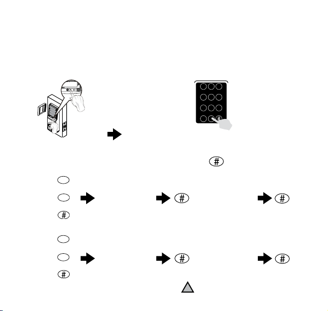
PROGRAMMING
ADD NEW USER ENTRY CODE OR SINGLE ENTRY CODE
FUNCTION CODE [ 20 ] ADD A USER CODE(S)
A user code (pin number) is set up by the programming code and can be used to unlock the lockset.
FUNCTION CODE
A single-use user code is set up by the programming code and can only be used once to unlock the lockset.
STEP 1
Press (SET) for 1 second
FUNCTION CODE [ 20 ] ADD A USER CODE(S)
STEP 2 STEP 3 STEP 4
FUNCTION CODE [ 21 ] ADD SINGLE ENTRY CODE(S)
STEP 2 STEP 3 STEP 4
23
® REGISTERED TRADEMARK OF TAYMOR INDUSTRIES LTD.
[ 21 ] ADD SINGLE ENTRY CODE(S)
Enter preset programming code
1-2-3-4-5-6-7-8 or current
programming code
2
+
0
+
2
+
1
+
New
User
Code (4-8 digits)
New
Single Entry
Code (4 digits)
1 2 3
4 5 6
7 8 9
c
0
+
New
User
Code (4-8 digits)
New
Single Entry
Code (4 digits)
The lockset will exit the programming mode and resume
!
to the stand-by status if no input is made in 10 seconds.
Page 27
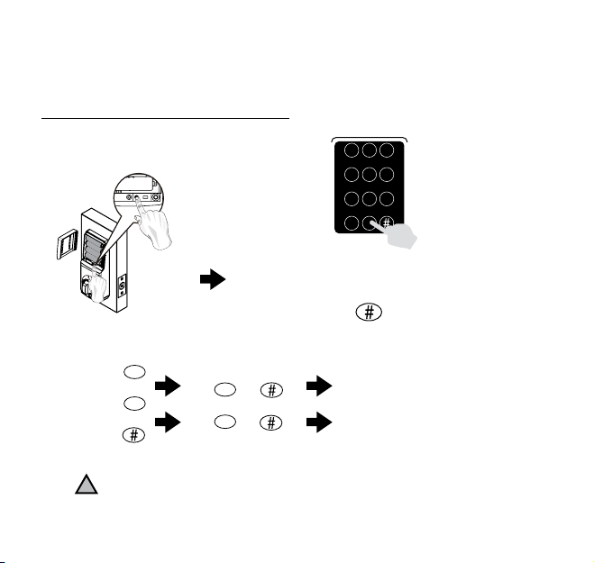
PROGRAMMING
ENABLE/DISABLE THE GUIDING CODE
The guiding code is a set of random numbers to be entered on the keypad
before entering the user entry code.
FUNCTION CODE [ 22 ]
STEP 1
Enter preset programming
code 1-2-3-4-5-6-7-8 or current
1 2 3
4 5 6
7 8 9
c
0
programming code
+
Press (SET) for 1 second
STEP 2 STEP 3 STEP 4
2
+
2
+
!
The lockset will exit the programming mode and resume to the stand-by status if no input is made in 10 seconds.
0
+
1
+
® REGISTERED TRADEMARK OF TAYMOR INDUSTRIES LTD.
TURN OFF
TURN ON
24
Page 28
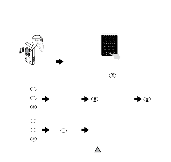
PROGRAMMING
DELETE USER CODE(S)
FUNCTION CODE [ 30 ] DELETE INDIVIDUAL USER CODE(S)
FUNCTION CODE [ 40 ] DELETE ALL USER CODE(S)
STEP 1
Enter preset programming code
Press (SET) for 1 second
FUNCTION CODE [ 30 ] DELETE INDIVIDUAL USER CODE(S)
STEP 2 STEP 3
3
+
0
User Code
(4-8 digits)
1-2-3-4-5-6-7-8 or current
+
FUNCTION CODE [ 40 ] DELETE ALL USER CODE(S)
STEP 2 STEP 3 STEP 4
25
4
+
0
+
® REGISTERED TRADEMARK OF TAYMOR INDUSTRIES LTD.
C
1 2 3
4 5 6
7 8 9
c
0
programming code
+
STEP 4
User Code
(4-8 digits)
Delete all
user codes
The lockset will exit the programming mode and resume
!
to the stand-by status if no input is made in 10 seconds.
Page 29
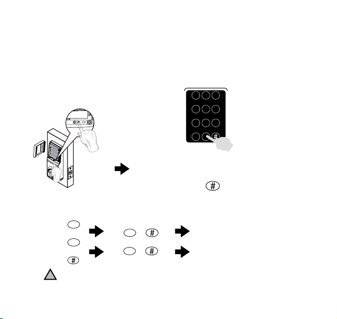
PROGRAMMING
ENABLE/DISABLE VACATION MODE
Temporarily disable all user codes (if enabled) until unit is re-enabled.
IMPORTANT: A valid key is required to unlock the door or the current
programming code to TURN OFF the Vacation Mode.
FUNCTION CODE [ 50 ]
STEP 1
Enter preset programming
code 1-2-3-4-5-6-7-8 or current
1 2 3
4 5 6
7 8 9
c
0
programming code
+
Press (SET) for 1 second
STEP 2 STEP 3 STEP 4
5
+
0
+
!
The lockset will exit the programming mode and resume to the stand-by status if no input is made in 10 seconds.
1
+
0
+
® REGISTERED TRADEMARK OF TAYMOR INDUSTRIES LTD.
TURN ON/ENABLE
TURN OFF/DISABLE
26
Page 30
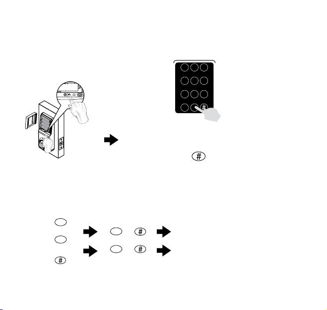
PROGRAMMING
VOLUME CONTROL Turn on / off door lock operation volume.
FUNCTION CODE [ 60 ]
STEP 1
Press (SET) for 1 second
STEP 2 STEP 3
6
+
0
+
27
® REGISTERED TRADEMARK OF TAYMOR INDUSTRIES LTD.
0
+
1
+
Enter preset programming
code 1-2-3-4-5-6-7-8 or current
1 2 3
4 5 6
7 8 9
c
0
programming code
+
0 - (TURN OFF)
1 - (TURN ON)
Page 31
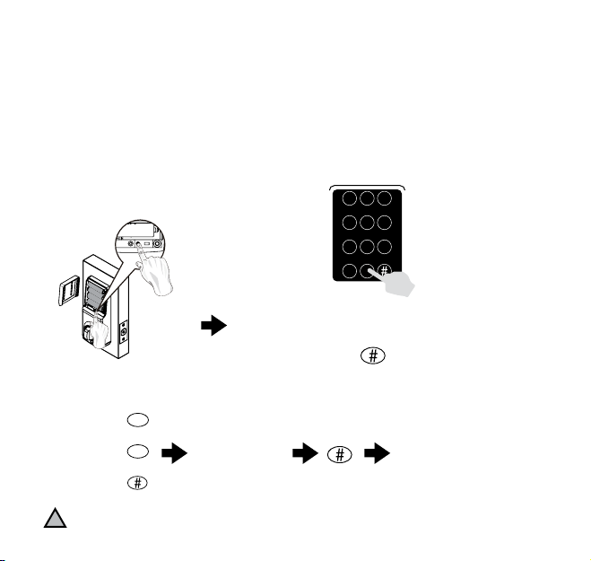
PROGRAMMING
SET UP AUTO-LOCK TIME DELAY
1. Default auto-lock time delay: 10 seconds.
2. Auto-lock time delay range: 10-99 seconds.
3. Three flashes and beeps will be presented if incorrect amount is
entered e.g. less than 10 or more than 99 seconds.
FUNCTION CODE [ 70 ]
STEP 1
Enter preset programming
code 1-2-3-4-5-6-7-8 or current
1 2 3
4 5 6
7 8 9
c
0
programming code
+
Press (SET) for 1 second
STEP 2 STEP 3 STEP 4
The lockset will exit the programming mode and resume
!
to the stand-by status if no input is made in 10 seconds.
7
+
0
+
ENTER NEW
AMOUNT
(10-99)
NEW AMOUNT
® REGISTERED TRADEMARK OF TAYMOR INDUSTRIES LTD.
28
Page 32
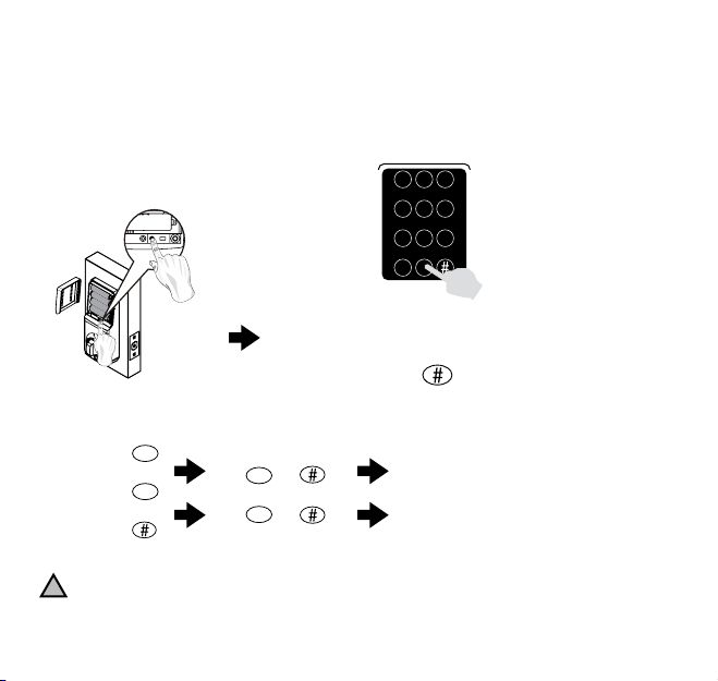
PROGRAMMING
ENABLE/DISABLE AUTO-LOCK FUNCTION
The lockset locks automatically in 10-99 seconds if enabled.
FUNCTION CODE [ 80 ]
STEP 1
Enter preset programming
code 1-2-3-4-5-6-7-8 or current
Press (SET) for 1 second
1 2 3
4 5 6
7 8 9
c
0
programming code
+
STEP 2 STEP 3 STEP 4
!
The lockset will exit the programming mode and resume to the stand-by status if no input is made in 10 seconds.
29
8
+
0
+
® REGISTERED TRADEMARK OF TAYMOR INDUSTRIES LTD.
0
+
1
+
TURN OFF
TURN ON
Page 33
PROGRAMMING
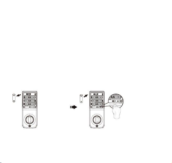
RESTORE FACTORY SETTING
IMPORTANT:
1. All existing user entry codes and the current programming code
will be deleted.
2. The lock will be restored to preset programming with the
programming code of 1-2-3-4-5-6-7-8.
3. Please re-enter the default Programming Code to set up the lock
after restoring to factory settings.
4. Please change the programming code and add a new user entry code
immediately before operating the lock.
AA
Remove one battery
AA
Press and hold SET
button while inserting
the battery back. Hold
the set button until
long beep has finished.
® REGISTERED TRADEMARK OF TAYMOR INDUSTRIES LTD.
30
Page 34
PROGRAMMING
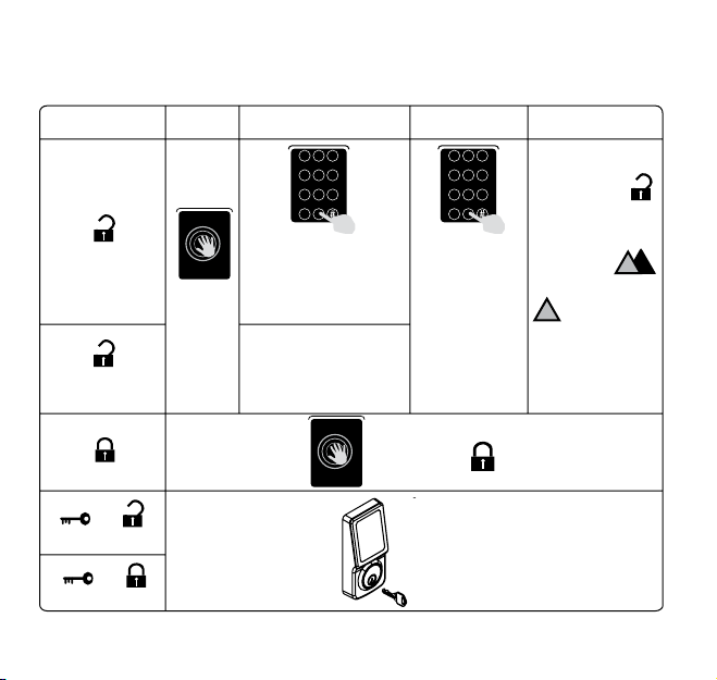
HOW TO LOCK/UNLOCK THE LOCKSET
OPERATION STEP 1 STEP 2 STEP 3 STEP 4
To Unlock
To Unlock
(Optional)
screen
Note:
enabled (see page 25
for function code 22),
press the four digits lit on
Touch
the screen)
the
Note: If guiding code is
disabled (see page 25
for function code 22),
proceed to step 3.
To Lock
→
To Unlock
→
To Lock
31
® REGISTERED TRADEMARK OF TAYMOR INDUSTRIES LTD.
1 2 3
4 5 6
7 8 9
c
0
If guiding code is
Touch
screen
the
→
1 2 3
4 5 6
7 8 9
c
0
Enter valid
user code
→
Correct
!
Touch screen
is temporarily
disabled after
4 consecutive
incorrect entries.
→
No
→
!
Page 35
OPERATION
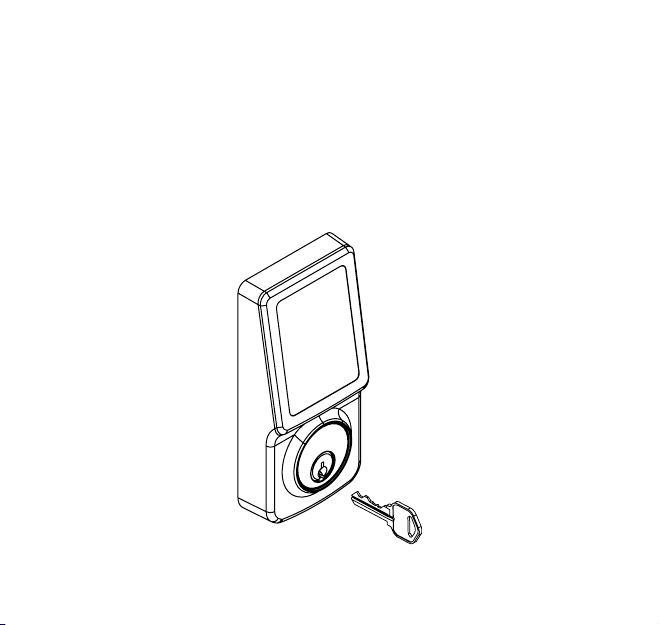
SECURITY MODE
1. The keypad will be automatically deactivated for 5 minutes after
4 unauthorized entry attempts.
2. The deadbolt can be locked or unlocked by a valid traditional key
under security mode.
→
® REGISTERED TRADEMARK OF TAYMOR INDUSTRIES LTD.
32
Page 36

TROUBLESHOOTING GUIDE - INSTALLATION
QUESTIONS ANSWERS
A. The latch does
not operate
correctly after
installation.
B. Feel a bump
while turning
the thumbturn
or the key.
33
® REGISTERED TRADEMARK OF TAYMOR INDUSTRIES LTD.
1. Make sure that the backset on the latch is set
to the proper length.
2. Make sure prior to installation latch bolt is
retracted and key are not in lockset when
placing torque blade horizontally through
latch.
1. Please execute lock & unlock function to
allow the motor to reposition itself again.
2. Redo the Automatic Bolt Direction Step
(page 19).
Page 37

TROUBLESHOOTING GUIDE - OPERATION
QUESTIONS ANSWERS
A.
Battery Indicator
keeps flashing.
B. Touch screen not
responding.
C. Programming
code cannot be
changed.
1. The batteries are getting low, please replace
with four new batteries for the best performance (alkaline batteries only).
1. Check the battery installation.
2. The batteries are getting low if the battery
keeps flashing, please replace with four new
batteries for the best performance (alkaline
batteries only).
3. Make sure the cable is well-connected
to the port, and was not damaged during
installation.
1. Please refer to page 31 in this installation
booklet to restore factory setting and
reprogram all codes.
® REGISTERED TRADEMARK OF TAYMOR INDUSTRIES LTD.
34
Page 38

TROUBLESHOOTING GUIDE - OPERATION
QUESTIONS ANSWERS
D.
What should
I do if wrong
code was
entered?
E. Cannot delete
all user codes.
F. Cannot add a
new user code
35
® REGISTERED TRADEMARK OF TAYMOR INDUSTRIES LTD.
1. Press button once and continue to input
code according to regular procedures.
1. Make sure the whole code entering process
is completed within 10 seconds, otherwise
the unit will time out.
2. Make sure the programming code has been
entered correctly.
1. Make sure the whole code entering process
is completed within 10 seconds, otherwise
the unit will time out.
2. Make sure the programming code has been
entered correctly.
3. The new user code will not be accepted
when the capacity if full. Try to delete any
or some existing user codes and then add
new one(s) again. A user code must be 4 to
8 digits.
Page 39

TROUBLESHOOTING GUIDE - OPERATION
QUESTIONS ANSWERS
G. “Auto Lock”
does not
function.
H. Lockset is not
able to unlock
by touch
screen.
I. Lockset is
unable to
reset.
1. The batteries are getting low, please
replace with four new batteries for the best
performance (alkaline batteries only).
1. Make sure you have entered the correct user
entry code.
2. The batteries are getting low if the battery
keeps flashing, please replace with four new
batteries for the best performance (alkaline
batteries only).
3. Check the strike plate to make sure it is
properly aligned & clear so the bolt can freely
enter the hole.
1. Please refer to page 31 in this installation
booklet to restore factory setting.
2. The batteries are getting low if the battery
keeps flashing, please replace with four new
batteries for the best performance (alkaline
batteries only).
® REGISTERED TRADEMARK OF TAYMOR INDUSTRIES LTD.
36
Page 40

TROUBLESHOOTING GUIDE - OPERATION
QUESTIONS ANSWERS
J. How to operate
the lockset in
darkness?
K. The red indicator is
still on after setting
is completed.
L. The lockset locks
when I enter my
code and unlocks
when I touch the
screen.
37
® REGISTERED TRADEMARK OF TAYMOR INDUSTRIES LTD.
1. Touch the screen to activate the lockset
1. Check if [SET] button is jammed.
2. Re-install the batteries.
1. Un-install the interior and exterior
back light.
assemblies. Before re-installation, please
follow these guidelines:
1) Make sure the bolt is in the retracted
position.
2) Do not have any key in the lock cylinder.
3) Make sure the torque blade is inserted
horizontally.
Page 41

TROUBLESHOOTING GUIDE - OPERATION
QUESTIONS ANSWERS
1. Un-install the interior and exterior
assemblies. Before re-installation, please
M. I cannot remove my
key unless it is in
the locked position.
If the lock appears to be damaged or does not function properly, please contact
Taymor Customer Service. taymor.com will provide you with contact
phone numbers.
follow these guidelines:
1) Make sure the bolt is in the retracted
position.
2) Do not have any key in the lock cylinder.
3) Make sure the torque blade is inserted
horizontally.
® REGISTERED TRADEMARK OF TAYMOR INDUSTRIES LTD.
38
Page 42
INFORMATION PAGE
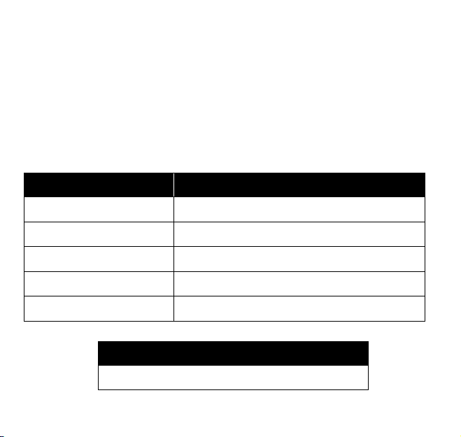
SECURITY INSTRUCTION
1. Do not share your programming code with anyone else.
2. Keep a written copy of all valid user entry codes in a safe place.
(You may use the table below to record your information)
3. You are advised to re-program all codes if you lost any security
information in the table.
NAME USER CODE
PROGRAMMING CODE
39
® REGISTERED TRADEMARK OF TAYMOR INDUSTRIES LTD.
Page 43

CONCIERGE 400
PROFESSIONAL SERIES
ELECTRONIC DEADBOLT
WARRANTY
Taymor’s
manufactured under the highest standards of quality and workmanship.
Taymor Locks are warranted to be free from finish defects for 5 (five)
years and free from mechanical, material and workmanship defects to
the original consumer/purchaser for the life of the product as long as the
original owner owns his/her home. Electronic components of this lock
are limited to 1 (one) year from the date of purchase. Taymor will replace
free of charge, during the warranty period, any part that fails to meet the
warranty under normal installation and use as long as the product has
been cared for according to the care instructions listed in the package
and on the website.
CONCIERGE 400 PROFESSIONAL SERIES ELECTRONIC DEADBOLT
For more details see www.taymor.com
is
IC REGULATIONS
This Class B digital apparatus complies with Canadian ICES-003. This device complies with
Industry Canada licence-exempt RSS-210 standard.
Operation is subject to the following conditions: (1) this device may not cause harmful
interference, and (2) this device must accept any interference received, including
interference that may cause undesired operation of the device.
® REGISTERED TRADEMARK OF TAYMOR INDUSTRIES LTD.
40
 Loading...