

Page 1
Model 500/561/600
SECTION 3. PARTS INFORMATION
3-1. INTRODUCTION This section lists and illustrates the replaceable parts of Henny
Penny Model 500, 561 and 600 pressure fryers built after
November 6, 2000. If your unit was built prior to that date, some
differences may exist. If you have any doubts, please contact your
distributor . As with all contacts to your distributor , include the
model number and serial number from the nameplate on your unit.
3-2. GENUINE P ARTS
3-3. MODEL VARIA TIONS
3-4. HOW TO FIND PARTS
Use only genuine Henny Penny parts in your fryer. Using a part of
lesser quality or substitute design may result in fryer damage or
personal injury .
This section covers model variations due to options, different
applications (gas or electric), and to cover the latest design
improvements. When you order replacement parts, be sure to
check for model variations as stated in the figure title and in the
DESCRIPTION column of the parts list.
T o find the items you want to order, proceed as follows:
1. Use the index of illustrations, paragraph 3-10, to find the page
number of the proper illustration.
2. Referring to the illustration, find the part desired and its item
number .
(SAMPLE)
504 3-1
Page 2
(SAMPLE)
Model 500/561/600
3. Find the item number in the corresponding parts list, which
shows the Henny Penny part number, a description of the part,
any model or usage limitations, and the quantity of parts used.
3-5. SUBASSEMBLIES
In some cases, items in the parts list can be purchased in groups
(called subassemblies) instead of purchasing individual parts. The
part list shows these subassemblies by indenting the description of
the parts included within the subassembly . For example:
TIMER, Automatic Reset
SWITCH, Timer
LIGHT , Timer Indicator
COIL, Timer Buzzer
The items can be ordered separately (switch, light, or coil), or order
the timer, and all three parts are included.
Once you have found the parts to be ordered, write down the
following information:
1. From the parts list: (SAMPLE)
Figure number 3-3
Item number 6
Part number 16918
Description DEADWEIGHT ORIFICE
Page number 3-11
Page date code 401
3-2 803
Page 3
Model 500/561/600
DATA PLATE
2. From the data plate on your unit: (SAMPLE)
Model number 500
Serial number 10133
3. The following table has been provided as a sample format for
you to use in preparing your spare parts orders. By providing
all the entries, your distributor will be able to send you the
correct parts. Also, prepayment expedites your order.
3-7. PRICES
Y our distributor has a priced parts list and will be glad to inform you
of the cost of your parts order .
3-8. DELIVERY
Commonly replaced items are stocked by your distributor and are
shipped when your order is received. Other parts are ordered, by
your distributor, from Henny Penny Corporation. Normally , these
are sent to your distributor within 3 working days.
3-9. WARRANTY
All replacement parts (except lamps and fuses) are warranted for
90 days against manufacturing defects and workmanship. If
damage occurs during shipping, notify the sender and the carrier at
once, so that a claim is properly filed. Refer to warranty in the front
of this manual for other rights and limitations.
3-10. RECOMMENDED
SPARE P ARTS FOR
DISTRIBUTORS
Recommended replacement parts, stocked by your distributor, are
indicated with
√ √
√ in the parts lists. Please use care when ordering
√ √
recommended parts, because all voltages and variations are
marked. Distributors should order parts based upon common
voltages and equipment sold in their territory .
1205 3-3
Page 4

Model 500/561/600
3-11. INDEX OF PARTS LIST ILLUSTRA TIONS
Title Fig. No. Page No.
AUTOMA TIC RESET TIMER ASSEMBL Y ................................................. 3-27 3-67
CONT ACTOR and FRAME ASSEMBL Y..................................................... 3-18 3-44
(Electric Model) Single Phase
CONT ACTOR and FRAME ASSEMBL Y..................................................... 3-17 3-42
(Three Phase Electric Model)
CONTROL PANEL, Standard....................................................................... 3-1 3-6
COUNTER TOP INSULATION ASSEMBLY (Gas Model) ........................... 3-10 3-28
DEADWEIGHT V AL VE ASSEMBL Y........................................................... 3-3 3-11
DIRECT -CONNECT ASSEMBL Y - MODEL 600....................................... 3-31 3-73
DIRECT -CONNECT ASSEMBL Y - MODEL 500....................................... 3-32 3-74
DRAIN VAL VE ASSEMBL Y (Electric Model)............................................... 3-7 3-21
DRAIN VAL VE ASSEMBL Y (Gas Model).................................................... 3-6 3-19
ELECTRIC CONDUIT ASSEMBL Y ............................................................ 3-26 3-65
ELECTRONIC IGNITION ASSEMBLY ...................................................... 3-30 3-71
EXHAUST ST ACK ASSEMBL Y .................................................................. 3-4 3-13
F AN and HIGH TEMPERATURE LIMIT CONTROL (Gas Model).............. 3-8 3-24
F AST CONTROL PANEL ............................................................................ 3-33 3-76
FIL TER DRAIN P AN and FIL TER SCREEN ASSEMBLY ........................... 3-20 3-51
FIL TER MOTOR and PUMP ........................................................................ 3-24 3-61
FIREBOX and FLUE ASSEMBL Y (Gas Model)............................................ 3-11 3-30
FIREBOX INSULA TION ASSEMBL Y (Gas Model) .................................... 3-12 3-32
FRAME and CABINET ASSEMBL Y ............................................................ 3-19 3-46
3-4 505
Page 5

Model 500/561/600
3-11. INDEX OF PAR TS LIST ILLUSTRA TIONS (continued)
Title Fig. No. Page No.
FRY BASKET ............................................................................................... 3-9 3-26
FRYPOT and GAS BURNER ASSEMBLY (Gas Model)............................... 3-14 3-36
GAS CONTROL VAL VE (Gas Model) ......................................................... 3-13 3-34
GAS LINE and BURNER ASSEMBLY - CE, INT’L, and ............................. 3-15 3-38
ELECTRONIC IGNITION (Gas Model)
HEA TING ELEMENT and HIGH LIMIT ASSEMBL Y (Electric Model) ........ 3-16 3-40
LID ASSEMBL Y ........................................................................................... 3-2 3-9
LOWER FIL TER PLUMBING COMPONENTS ......................................... 3-21 3-53
SOLENOID V AL VE ASSEMBL Y................................................................. 3-5 3-17
SUPERSORB FIL TER P AN ASSEMBL Y (Before 3-1-02) ........................... 3-22 3-56
SUPERSORB FIL TER P AN ASSEMBL Y (3-1-02 & After) .......................... 3-23 3-59
UPPER FIL TER PLUMBING COMPONENTS ........................................... 3-25 3-63
3 TIER WIRE BASKET (Gas Model)............................................................ 3-28 3-69
4 TIER WIRE BASKET (Electric Model) ...................................................... 3-29 3-70
904 3-5
Page 6
Model 500/561/600
Figure 3-1. Standard Control Panel
3-6 1205
Page 7
Model 500/561/600
FIGURE UNITS
& ITEM PART PER
NO. NUMBER DESCRIPTION ASSY
3-1 CONTROL PANEL, Standard
18425 ASSY, Control Panel Complete-Bent Panel - 500 ......................... 1
48185 ASSY, Control Panel Complete-Bent Panel - 561 ......................... 1
16675 ASSY, Control Panel Complete-Bent Panel - 600 ......................... 1
√√
√ 1 16602 TIMER, Automatic Reset, 115 Volt, 60 Hz .................................... 1
√√
√√
√ 1 16596 TIMER, Automatic Reset, 115 Volt, 50 Hz .................................... 1
√√
√√
√ 1 18301 TIMER, Automatic Reset, 208-240 Volt, 60 Hz ............................. 1
√√
√√
√ 1 18304 TIMER, Automatic Reset, 208-240 Volt, 50 Hz ............................. 1
√√
√√
√ 1 17366 TIMER, Automatic Reset, 208-240 Volt, 50 Hz - CE .................... 1
√√
√√
√ 2 22195 SWITCH, Timer ............................................................................. 1
√√
√√
√ 3 16624 LIGHT, T imer Indicator.................................................................. 1
√√
√√
√ 4 16659 COIL, Timer Buzzer, 1 15 V olt................................................. 1
√√
√√
√ 4 18302 COIL, Timer Buzzer, 220 Volt ................................................ 1
√√
4 14283 KIT , 600, Cont. 120 EM Buzzer .................................................... 1
4 14284 KIT , 500/600, Cont. 230 EM Buzzer ............................................. 1
4 14419 KIT , 500, Cont. 24 EM Buzzer ...................................................... 1
5 SC01-073 SCREW, T imer .............................................................................. 4
√√
√ 6 16624 LIGHT, Indicator ........................................................................... 3
√√
√√
√ 6 63609 LIGHT, Indicator, Temperature - 48 Volt - Gas Models ................ 1
√√
√
√
√ 6 54086 LIGHT , Indicator, Green-CE and Australia - Gas Models............. 3
√√
7 NS02-009 NUT, T imer.................................................................................... 4
8 DECAL, Control - See chart on next page................................ 1
√√
√ 9 16640 SWITCH, Main .............................................................................. 1
√√
10 NS03-018 NUT , Main Switch......................................................................... 2
11 16745 PLATE, Thermostat ....................................................................... 1
12 PANEL, Stud Assy - Control - See chart on next page............. 1
13 SC04-003 SCREW, Control Panel.................................................................. 2
√√
√ 14 14293 KIT , Thermostat Control - 600 ...................................................... 1
√√
√√
√ 14 14648 KIT , Thermostat Control - 500/561................................................ 1
√√
√√
√ 14 18382 THERMOSTAT, RS KX 365F Max.-CE - 500/600 ..................... 1
√√
15 16706 KNOB, Thermostat ................................................................ 1
16 16704 BEZEL, Thermostat ............................................................... 1
17 SC01-023 SCREW, Thermostat .............................................................. 2
18 65183 ASSY , Pot Capillary Guard - 500/561..................................... 1
19* 32927 WRAP , Thermostat Capillary ........................................................ 1
F AST Controls (Also see pgs. 3-75 & 76 for exploded view & details)
20* 61722 Decal - FAST Controls .................................................................. 1
√√
√ 2 1* 29898 Power Switch ................................................................................. 1
√√
22* 18450 Guard - Power Switch ................................................................... 1
√√
√ 2 3* 60818 Relay - 24 VAC ............................................................................. 2
√√
√√
√ 2 4* 30614 Transformer - 208/240 V - Pri 24 VS............................................ 1
√√
√√
√ 2 5* 54085 Indicator Light - Green - CE.......................................................... 3
√√
26* 27472 Control Panel Assy. - FAST - 600 - 100-120V.............................. 1
26* 27423 Control Panel Assy. - FAST - 500/600 - 240V .............................. 1
√√
√ 2 7* 29948 Temperature Probe - FAST - 500.................................................. 1
√√
√√
√ 2 7* 29383 Temperature Probe - FAST - 600.................................................. 1
√√
√√
Recommended Parts/* Not shown
√
√√
1205 3-7
Page 8
Model 500/561/600
Standard Control Panel
SN 500 561 600
KB020JJ & Control Decal 64427 - Below Control Decal-Wendy's 61570 - -
Control Decal-Pollo Campero 61572 - -
Control Panel Stud Assy 18439 - KB029JJ & Control Decal - 64428 Below Control Panel Stud Assy - 17524 KA020JJ & Control Decal - - 64429
Below Control Decal-Wendy's - - 61571
Control Decal-Pollo Campero - - 61580
Control Decal-Pollo Campero-CE - - 61754
Control Panel Stud Assy - - 16701
KB021JJ to Control Decal 61554 - HB013JB Control Decal-Wendy's 61570 - -
Control Decal-Pollo Campero 61572 - -
Control Panel Stud Assy 63230 - KB030JJ to Control Decal - 61709 HB016JB Control Panel Stud Assy - 63230 KA021JJ to Control Decal - - 61555
GA085JB Control Decal-Wendy's - - 61571
Control Decal-Pollo Campero - - 61580
Control Panel Stud Assy - - 63230
Control Decal-Pollo Campero-CE - - 61754
HB014JB & Control Decal 61554 - Above Control Decal-Wendy's 61570 - -
Control Decal-Pollo Campero 61572 - -
Control Panel Stud Assy 27396 - HB017JB & Control Decal - 61709 Above Control Panel Stud Assy - 27396 GA086JB & Control Decal - - 61555
Above Control Decal-Wendy's - - 61571
Control Decal-Pollo Campero - - 61580
Control Decal-Pollo Campero-CE - - 61754
Control Panel Stud Assy - - 27396
3-8 904
Page 9
Model 500/561/600
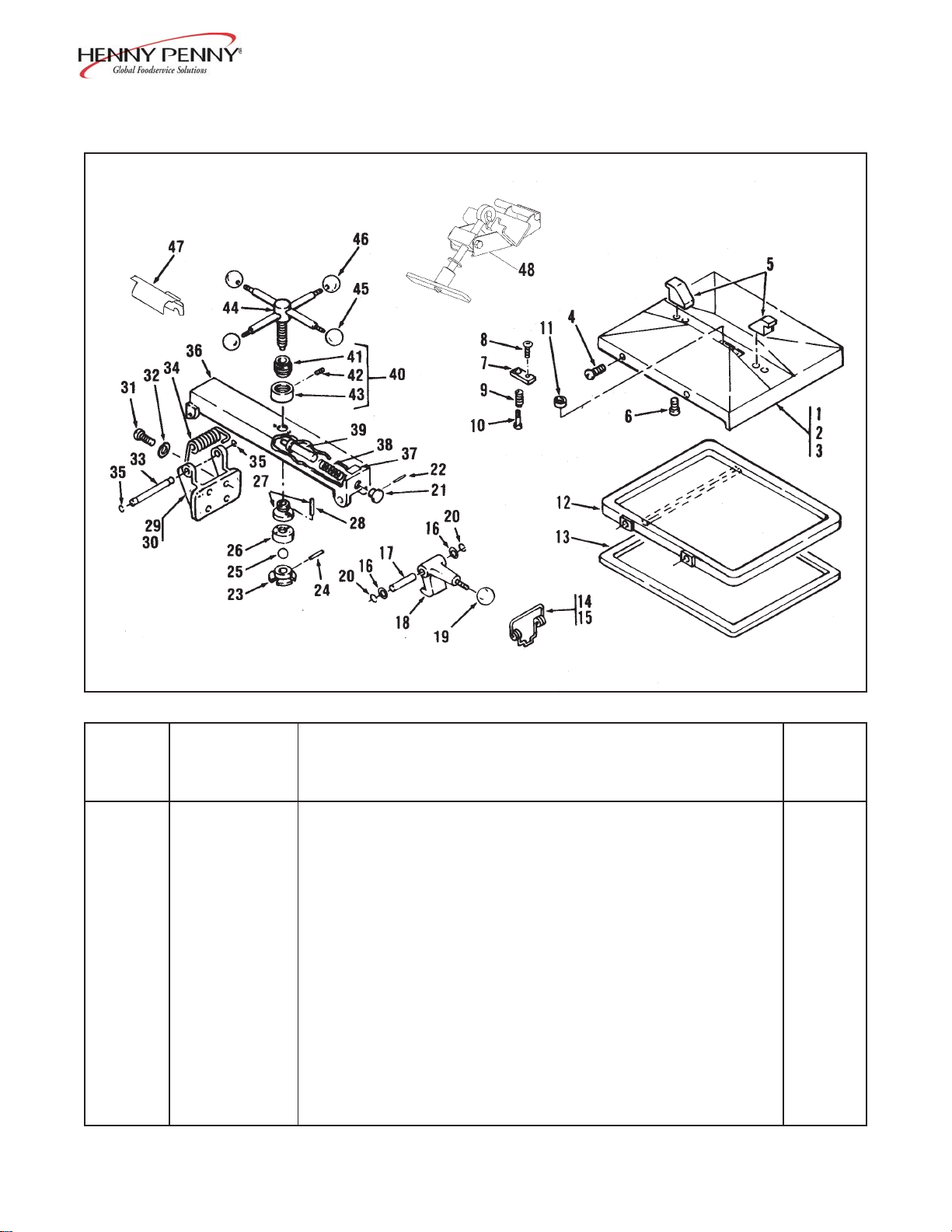
Figure 3-2. Lid Assembly
FIGURE UNITS
& ITEM P AR T PER
NO. NUMBER DESCRIPTION ASSY
3-2 LID ASSEMBL Y
1 16170 LID ASSEMBLY ................................................................... 1
2 16169 COVER ASSEMBL Y....................................................... 1
3 16155 COVER, Lid .............................................................. 1
4 SC01-083 SCREW , Lid Cover ................................................... 4
5 16133 HOOK, Cover Retaining. ........................................... 2
6 SC06-027 SCREW , Retaining Hook ........................................... 4
7 16166 RETAINER................................................................ 1
8 SC06-010 SCREW , Retaining Hook (Allen Head) ....................... 1
9 16165 SPRING , Return......................................................... 1
10 16164 PIN, Locking ............................................................. 1
11 16163 BALL, Seat................................................................ 1
√√
√ Recommended Parts
√√
1205 3-9
Page 10
Model 500/561/600
FIGURE UNITS
& ITEM P AR T PER
NO. NUMBER DESCRIPTION ASSY
3-2 Cont’d.
12 16119 LINER, Inner Lid .......................................................... 1
√√
√
13 16120 GASKET , Reversible, Inner Lid Liner............................ 1
√√
√√
14 16199 KIT, Latch Spring................................................................ 1
√
√√
15 33480 SPRING ....................................................................... 1
16 16198 SPACER ...................................................................... 2
17 16197 PIN, Latch .................................................................... 1
√√
√
18 16116 LA TCH, Lid........................................................................ 1
√√
19 16102 KNOB, Latch ..................................................................... 1
20 16121 RING , Tru-Arc Latch .......................................................... 2
21 16137 KNOB, Retaining Pin .......................................................... 1
22 16138 PIN, Knob Roll ................................................................... 1
23 16157 COLLAR, Locking ............................................................. 1
23 27325 COLLAR, Locking - CE ..................................................... 1
24 16158 PIN, Locking Collar ............................................................ 1
25 16159 BALL, Thrust ...................................................................... 1
26 27326 NUT, Idle............................................................................ 1
27 27329 NUT, Acme......................................................................... 1
28 16162 PIN, Acme Nut............................................................. 2
√√
√
29 16112 HINGE, Lid Assembly ......................................................... 1
√√
30 40235 HINGE, Lid .................................................................. 1
30 44339 HINGE, Lid - CE ......................................................... 1
31 SC01-081 SCREW , Lid Hinge....................................................... 4
32 LW01-010 WASHER, Lock, Lid Hinge .......................................... 4
33 16110 PIN, Lid Hinge.............................................................. 1
√√
√
34 16108 HINGE, Lid Spring ............................................................. 1
√√
√√
√ 34 27382 HINGE, Lid Spring - CE ..................................................... 1
√√
35 1611 1 RING , Retainer, Tru-Arc, Hinge ........................................... 2
36 16154 BAR, Center Cross ............................................................. 1
36 26884 BAR, Center Cross - CE..................................................... 1
37 36099 DECAL, DANGER ............................................................ 1
38 16136 SPRING , Retaining Pin ........................................................ 1
39 16135 COVER, Retaining Pin ........................................................ 1
40 16171 STOP, Limit Assembly ......................................................... 1
41 16153 STOP, Limit .................................................................. 1
42 16156 SCREW , Set, Limit Stop Collar..................................... 2
43 16152 COLLAR, Limit Stop.................................................... 2
44 16168 SPINDLE ASSEMBLY ...................................................... 1
44 26911 SPINDLE ASSEMBL Y - CE .............................................. 1
45 16102 KNOB, Spindle, Red .......................................................... 1
46 16101 KNOB, Spindle, Black ........................................................ 3
47 29587 COVER, Spring .................................................................. 1
√√
√ 48 21642 TOOL, Spring Loading ........................................................ 1
√√
√√
√ Recommended Parts
√√
3-10 806
Page 11
Model 500/561/600
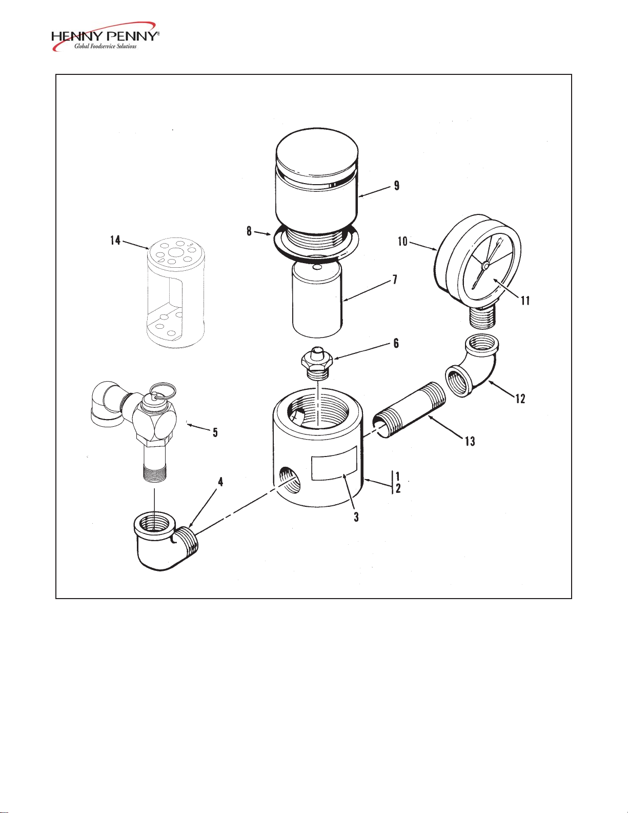
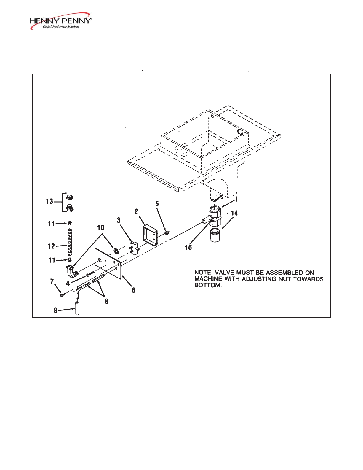
NOTE: T urn safety relief valve towards
rear of fryer.
Figure 3-3. Deadweight Valve Assembly
1205 3-11
Page 12
Model 500/561/600
FIGURE UNITS
& ITEM P AR T PER
NO. NUMBER DESCRIPTION ASSY
3-3 DEADWEIGHT VAL VE ASSEMBL Y
1 16924 VALVE ASSEMBL Y , Deadweight.......................................... 1
2 56305 BODY , Deadweight V alve .......................................... 1
3 16912 DECAL, DEADWEIGHT V AL VE............................. 1
4 FP01-127 1/2 x 1/2 90 Degree Street L ...................................... 1
√√
5 59742 VALVE ASSEMBL Y, Relief ....................................... 1
√
√√
6 16918 DEADWEIGHT ORIFICE . ............................................. 1
6 27910 DEADWEIGHT ORIFICE - 3 lb. (use w/28922) . ........... 1
7 16903 DEADWEIGHT - 12 lb. ................................................... 1
7 28922 DEADWEIGHT - 3 lb (use w/27910)............................... 1
7 32729 DEADWEIGHT - 7 lb. ..................................................... 1
8 16902 RING , Cap ....................................................................... 1
9 56307 CAP, Deadweight V alve .................................................... 1
√√
√
10 16910 GAUGE, Pressure .................................................................. 1
√√
11 16914 GLASS, Pressure Gauge ........................................................ 1
12 16909 ELBOW ................................................................................ 1
13 56636 NIPPLE ................................................................................. 1
14 65449 DEADWEIGHT - 3 lb. .......................................................... 1
√√
√
Recommended Parts
√√
3-12 1205
Page 13
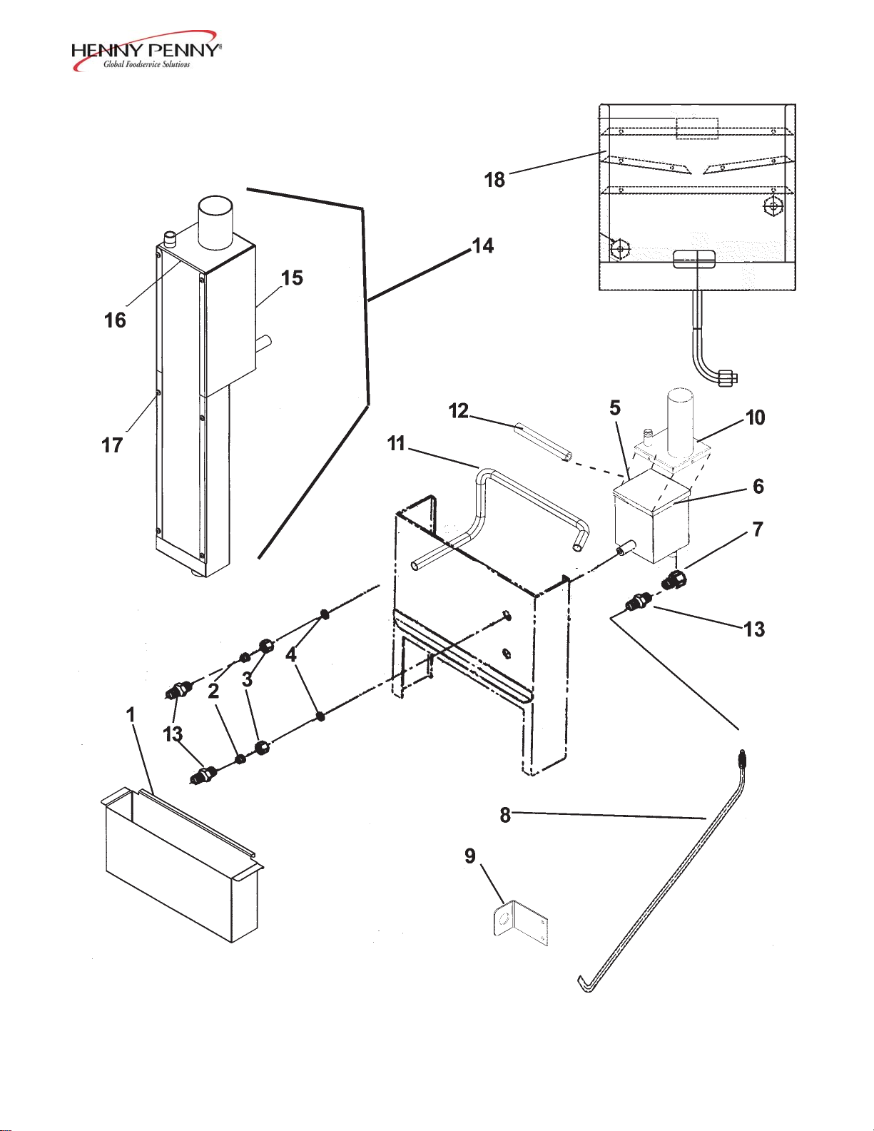
Model 500/561/600
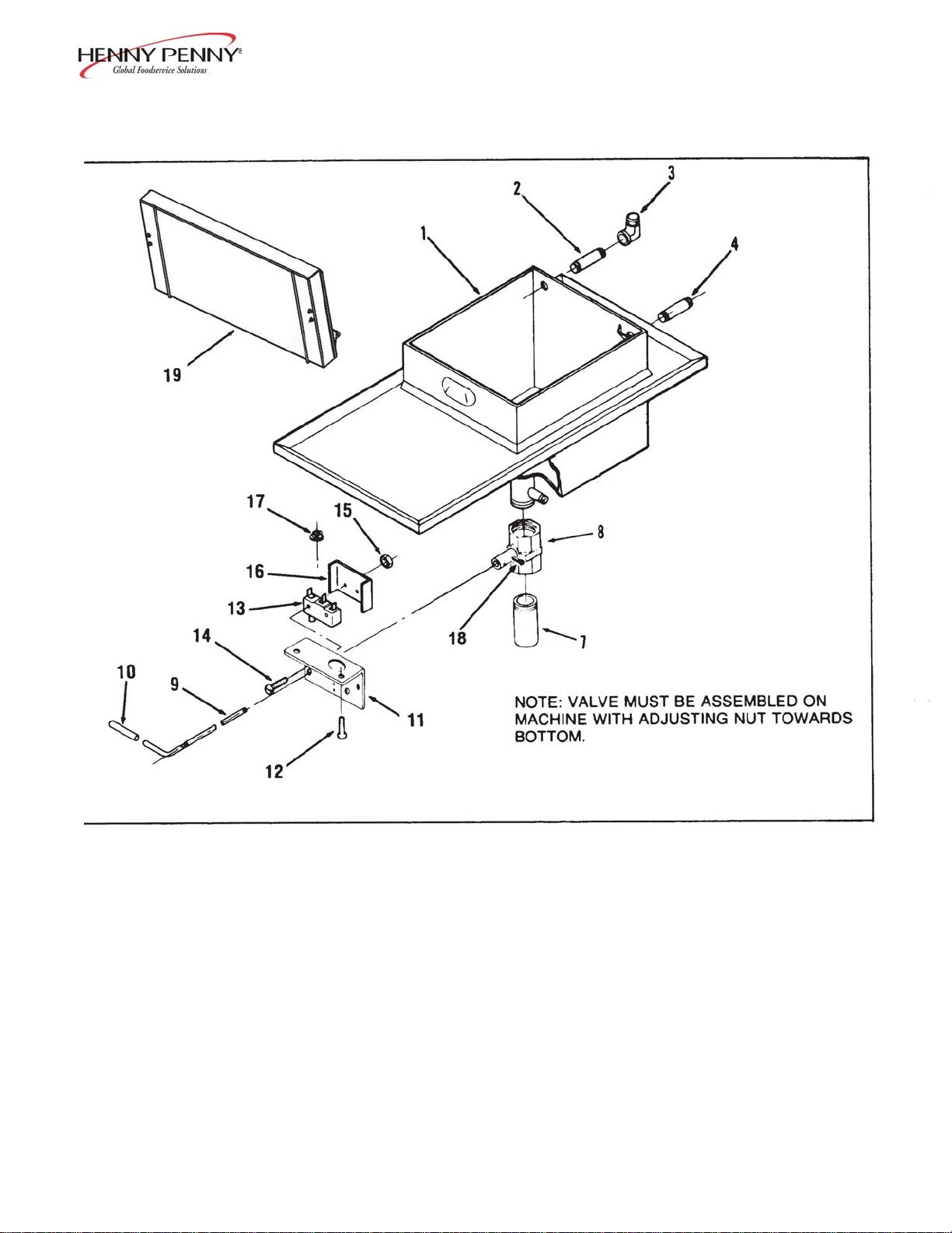
Figure 3-4. Exhaust Stack Assembly
806 3-13
Page 14
Model 500/561/600
FIGURE UNITS
& ITEM P AR T PER
NO. NUMBER DESCRIPTION ASSY
3-4 EXHAUST ST ACK ASSEMBL Y
1 68086 PAN, Condensation Drain ...................................................... 1
1 64274 PAN, Condensation Drain - Short
(CF A-SN: JB095JA to HB013JB) 1
2 16817 FITTING , Teflon Sleeve ......................................................... 2
3 16809 NUT, Fitting ........................................................................... 2
4 16804 UMBRELLA GROMMET ..................................................... 2
5 58852 CONDENSA TE BOX - Bottom-See chart on next page..... 1
6 SC02-016 SCREW , #8-32-AB x 1/2 PH PHD S.................................... 4
7 FP01-122 REDUCER, 3/8 to 1/2 BI....................................................... 1
8 TUBE, Condensation Assembly-See chart on next page....... 1
9 63992 BRACKET, Condensation Hose............................................. 1
10 64013 CONDENSA TE BOX - Top-See chart on next page .......... 1
1 1 TUBE, Deadweight-See chart on next page ......................... 1
12 HOSE, Deadweight to Steam Box-See chart on next page... 1
13 16807 CONNECTOR, Male............................................................ 3
14 65724 ASSY , Condensate Box-See chart on next page.................. 1
15 65725 WELD ASSY, Steam Box - Outer .................................... 1
16 65726 WELD ASSY, Steam Box - Inner ..................................... 1
17 SC04-003 SCREW, #8-32 x 3/8 PH PHD S ..................................... 6
18 21302 ASSY , Exhaust Stack - 500/561 - SN: KB020JJ & Below..... 1
3-14 806
Page 15
Model 500/561/600
Exhaust Stack Assembly
Item No. SN Description 500 561 600
8 KB020JJ & Condensation Line Assy 18502 - -
Below
8 KB029JJ & Condensation Line Assy - 55432 -
Below
8 KA020JJ & Condensation Line Assy - - 16838
Below Dead Wt. Tube - - 16854
8 KB021JJ to Condensation Line Assy 14320 - 10 BB016JA Condensate Box Top 64013 - 11 Dead Wt. Tube 59221 - 12 DW To Steam Box Hose 63195 - -
5 Condensate Box 58852 - -
8 KB030JJ to Condensation Line Assy - 14320 10 BB055JA Condensate Box Top - 64013 11 Dead Wt. Tube - 59221 12 DW To Steam Box Hose - 63195 -
5 Condensate Box - 58852 -
8 KA021JJ to Condensation Line Assy - - 14320
10 BA026JA Condensate Box Top - - 64013
11 Dead Wt. Tube - - 59221
12 DW To Steam Box Hose - - 63195
5 Condensate Box - - 58852
8 BB017JA to Condensation Line Assy 64016 - 10 EB015JB Condensate Box Top 64013 - 11 Dead Wt. Tube 59221 - 12 DW To Steam Box Hose 63195 - -
5 Condensate Box 58852 - -
8 BB056JA to Condensation Line Assy - 64016 10 EB019JB Condensate Box Top - 64013 11 Dead Wt. Tube - 59221 12 DW To Steam Box Hose - 63195 -
5 Condensate Box - 58852 -
8 BA027JA to Condensation Line Assy - - 64016
10 EA014JB Condensate Box Top - - 64013
11 Dead Wt. Tube - - 59221
12 DW To Steam Box Hose - - 63195
5 Condensate Box - - 58852
(Continued on following page)
807 3-15
Page 16
Model 500/561/600
Exhaust Stack Assembly
Item No. SN Description 500 561 600
8 EB016JB to Condensation Line Assy 24998 - 10 HB013JB Condensate Box Top
11
(except Dead Wt. Tube 65621 - -
use 65724
12 EB018JB & DW To Steam Box Hose 26866 - -
5 EB019JB) Condensate Box Bottom
14 Condensate Box
use 65724
use 65724
8 EB020JB to Condensation Line Assy - 24998 10 HB016JB Condensate Box Top 11 Dead Wt. Tube
- 65621
12 DW To Steam Box Hose -
5 Condensate Box Bottom 14 Condensate Box -
8 EA015JB to
Condensation Line Assy - - 24998
10 GA085JB Condensate Box Top - 11 Dead Wt. Tube
- - 65621
12 DW To Steam Box Hose - -
5 Condensate Box Bottom - -
14 Condensate Box - -
--
--
--
use 65724
26866
use 65724
use 65724
use 65724
26866
use 65724
use 65724
-
-
-
-
8 HB014JB &
11 Above Dead Wt. Tube
12 DW To Steam Box Hose
14 Condensate Box
8 HB017JB &
11 Above Dead Wt. Tube 12 DW To Steam Box Hose 14 Condensate Box -
8 GA086JB &
Condensation Line Assy 69009
65621
26866
65724
Condensation Line Assy
Condensation Line Assy
-
--
69009
65621
26866
65724
11 Above Dead Wt. Tube - 12 DW To Steam Box Hose - 14 Condensate Box - -
--
--
--
--
-
-
-
-
69009
65621
26866
65724
3-16 806
Page 17
Model 500/561/600
Figure 3-5. Solenoid Valve Assembly
905 3-17
Page 18
Model 500/561/600
FIGURE UNITS
& ITEM P AR T PER
NO. NUMBER DESCRIPTION ASSY
.
3-5 SOLENOID V AL VE ASSEMBL Y
(Gas and Electric Models)
1 17121 VALVE, Solenoid, 120 V olt, 60 Cycle .................................... 1
1 18724 VALVE, Solenoid, 208-240 Volt, 50 Cycle............................. 1
1 18721 VALVE, Solenoid, 208/240 Volt, 60 Cycle ............................. 1
1 29515 VALVE, Solenoid, 24 V olt, 60 Cycle ...................................... 1
1 29698 VALVE, Solenoid, 24 V olt, 50 Cycle ...................................... 1
1 54945 VALVE, Solenoid, 208-240 Volt, 50 Cycle-CE ...................... 1
1 54971 VALVE, Solenoid, 24 V olt, 50 Cycle-CE................................ 1
√√
√
2 17120 KIT, Solenoid V alve Repair............................................... 1
√√
3 17101 CLIP , Retaining .......................................................... 1
4 17109 RETAINER, Spring .................................................... 1
5 171 10 SPRING, Core ........................................................... 1
6 17111 CORE, Disc Assembly ............................................... 1
7 17112 GASKET, Bonnet ...................................................... 1
8 171 14 SEA T , T eflon .............................................................. 1
9 17115 GUIDE, Disc Spring ................................................... 1
10 17116 SPRING , Disc............................................................ 1
11 17117 RING , Spring Retainer ................................................ 1
12 17122 SEAT, O-Ring Seal..................................................... 1
√√
√
13 17102 PLATE, Solenoid Name .................................................... 1
√√
√√
√
14 17103 COVER, Coil Housing ...................................................... 1
√√
√√
√
15 17104 WASHER, Coil................................................................. 2
√√
√√
√
16 17105 YOKE, Coil ..................................................................... 1
√√
√√
√
17 17106 COIL, 120 V olt, 60 Cycle................................................. 1
√√
√√
√
17 18706 COIL, 208/240 V olt, 60 Cycle.......................................... 1
√√
√√
√ 17 18726 COIL, 208-240 Volt, 50 Cycle ......................................... 1
√√
√√
√
17 29547 COIL, 24 V olt, 60 Cycle................................................... 1
√√
√√
√
18 17123 HOUSING , Coil ............................................................... 1
√√
√√
√ 19 17108 BONNET , Solenoid.......................................................... 1
√√
√√
√
20 17113 BODY, Solenoid V alve...................................................... 1
√√
√√
√ 21 17118 ADAPTER, Pipe .............................................................. 1
√√
√√
√ 22 SC01-132 SCREW , Adapter ............................................................. 2
√√
√√
√ Recommended Parts
√√
3-18 1205
Page 19
Model 500/561/600
Figure 3-6. Drain Valve Assembly (Gas Model)
803 3-19
Page 20

Model 500/561/600
FIGURE UNITS
& ITEM P AR T PER
NO. NUMBER DESCRIPTION ASSY
3-6 DRAIN V AL VE ASSEMBL Y
(Gas Model)
1 17261 BODY , Drain V alve (June 1998 and above) ................ 1
1 55152 ASSY, Drain V alve and Coupling
(May 1998 and below) 1
2 17210 COVER, Microswitch ................................................ 1
√√
√
3 18227 MICROSWITCH ...................................................... 1
√√
4 SC01-058 SCREW , Microswitch ................................................ 2
5 NS02-005 NUT, Microswitch ...................................................... 2
6 l72l1 BRACKET , Drain, V alve Rod .................................... 1
7 SC03-005 SCREW , Drain Bracket.............................................. 2
8 17254 ROD, Drain V alve - Normally Closed ......................... 1
8 67661 ROD, Drain V alve - Normally Open ........................... 1
9 16293 COVER, V alve Handle ............................................... 1
10 18644 CONNECTOR, 90° Flexible Conduit ........................ 1
(Includes Nut)
11 18105 INSULA T OR............................................................. 2
12 17214 CONDUIT, Flexible................................................... 1
13 18111 CONNECTOR, Flexible Conduit ............................... 1
(Includes Nut)
14 18819 EXTENSION NIPPLE (SN: KA020JJ and below) .... 1
14 18817 EXTENSION NIPPLE (SN: KA021JJ to GA085JB) 1
14 24647 EXTENSION & DEFLECTOR ................................. 1
(SN: GA086JB and above)
15 17255 PIN, Cotter ................................................................ 2
√√
√
16* 14652 KIT, PFG600 Norm Open Drain Switch..................... 1
√√
√√
√ Recommended/*not shown
√√
3-20 1205
Page 21
Model 500/561/600
Figure 3-7. Drain Valve Assembly (Electric Model)
806 3-21
Page 22
Model 500/561/600
FIGURE UNITS
& ITEM P AR T PER
NO. NUMBER DESCRIPTION ASSY
3-7 DRAIN V AL VE ASSEMBL Y
(Electric Model)
1 TOP ASSEMBL Y, Pot and Counter-See chart on next page 1
2 18816 NIPPLE, Pipe ........................................................................ 1
3 16239 ELBOW ................................................................................ 1
4 18816 NIPPLE, Pipe ........................................................................ 1
7 NIPPLE, Drain Extension-See chart on next page................ 1
8 17261 BODY , Drain Valve (SN: FB099IH and above)...................... 1
8 55152 ASSY , Drain Valve and Coupling (SN: FB098IH and below).. 1
9 18818 ROD, Drain V alve Extension - Normally Closed ..................... 1
9 66123 ROD, Drain V alve Extension - Normally Open........................ 1
9 44907 ROD, Drain V alve Extension - 561 (Before 11-12-02)............ 1
10 16293 COVER, V alve Handle........................................................... 1
11 BRACKET , Filter & Drain Rod -See chart on next page ..... 1
12 SC03-005 SCREW , Drain Valve Bracket ................................................ 2
√√
√
13 18227 MICROSWITCH .................................................................. 1
√√
14 SC01-058 SCREW , Microswitch............................................................ 2
15 NS02-005 NUT, Microswitch ................................................................. 2
16 18528 COVER, Microswitch ............................................................ 1
16 COVER, Microswitch - 561 -See chart on next page .......... 1
17 EF02-004 BUSHING , Snap ................................................................... 1
18 17255 PIN, Cotter............................................................................ 2
19 03512 KIT, Holder for UHC Tray (McD’ s-Optional) ........................ 1
19 03531 ACCESSORY, 1/2 Size Bun Pan Holder (McD’s-Optional) ... 1
20* 59964 INSULATION, Front Panel - 561 (500 elements) .................. 1
21* 59956 INSULATION, Right Side Panel - 561 (500 elements)........... 2
22* 55412 INSULATION, Rear Panel - 561 (500 elements) ................... 1
23* 59955 SHROUD, Control Panel-Rear - 561 (500 elements) ............. 1
24* 55417 INSULATION, Rear Panel - 561 (500 elements) ................... 1
25* 59957 INSULATION, Side Panel - 561 (500 elements).................... 2
26* 63339 INSULATION, Front Panel - 561 (500 elements) .................. 1
√√
√ 27* 14653 KIT, PFE500 Norm Open Drain Switch................................. 1
√√
√√
√ Recommended
√√
3-22 806
Parts/*not shown
Page 23
Model 500/561/600
Frypot & Drain Valve Assembly
SN 500 561
KB020JJ & Bracket - Drain Rod 18419 Below Drain Extension 18817 -
Pot & Countertop 18921 KB029JJ & Bracket - Drain Rod - 44847
Below Pot & Countertop - 56071
Pot & Coun tertop w/Firebar - 44455
Dr ain Switch Cover - 48033
KB021JJ to Bracket - Drain Rod 63193 HB013JB Drain Extension 18817 -
Pot & Countertop 65025 -
Pot & Countertop(Pollo Ca mpero)
KB030JJ to Bracket - Drain Rod - 59958
HB016JB Pot & Countertop - 65198
Front Panel - 56974
Dr ain Switch Cover - 59954
HB014JB & Bracket - Drain Rod 23917 Above Drain Extension & Deflector 24633 -
Pot & Countertop 65025 -
Pot & Countertop(Pollo Ca mpero)
Frame Assy(short) 23679 -
Frame Assy(long) 26854 HB017JB & Bracket - Drain Rod - 23756
Above Drain Extension & Deflector - 24638
Pot & Countertop - 65024
Frame Assy(short) - 23679
Frame Assy(long) - 26854
Dr ain Switch Cover - 23757
65027
65027
105 3-23
Page 24

Model 500/561/600
Figure 3-8. Fan and High Temperature Limit Control (Gas Model)
3-24 105
Page 25

Model 500/561/600
FIGURE UNITS
& ITEM P AR T PER
NO. NUMBER DESCRIPTION ASSY
3-8 F AN AND HIGH TEMPERATURE LIMIT
CONTROL (Gas Model)
√√
√
1 16738 CONTROL, High T emperature Limit ......................................... 1
√√
√√
√
1 60241 CONTROL, High T emperature Limit-E.G .O.-CE and Australia .. 1
√√
SN: CA012JJ and above
√√
√
1 14267 KIT, High Limit - CE SN: CA011JJ and below ........................ 1
√√
2 SC02-018 SCREW , Thread Forming #8..................................................... 2
3 NS02-001 NUT, #10-32 Hex Keps ........................................................... 2
4 17216 BRACKET ASSY, High Limit Thermostat ................................. 1
√√
√
5 16684 FAN, 120 Volt .......................................................................... 1
√√
√√
√
5 16688 FAN, 240 Volt .......................................................................... 1
√√
6 SC01-010 SCREW , Fan ............................................................................ 4
7 WA01-006 WASHER, Fan.......................................................................... 4
8 NS02-005 NUT, Fan.................................................................................. 4
√√
√
9 35916 TRANSFORMER, 120V -Pri./24V-Sec. ................................... 1
√√
√√
√ 9 30614 TRANSFORMER, 208/240V -Pri./24V-Sec. ............................ 1
√√
10 51071 FITTING , Thermostat - SN: KA020JJ & Below........................ 2
√√
√
11 68078 ASSY , FPS T emperature Probe (when applicable)..................... 1
√√
12* 36097 PROBE GUARD ...................................................................... 1
√√
√ Recommended
√√
*not shown
1205 3-25
Parts
Page 26

Model 500/561/600
6
3
4
5
Figure 3-9. Fry Basket
3-26 504
Page 27

Model 500/561/600
FIGURE UNITS
& ITEM P AR T PER
NO. NUMBER DESCRIPTION ASSY
3-9 FR Y BASKET (Gas and Electric Models)
1 56075 BASKET, Model 561 .......................................................... 1
1 55424 BASKET, Full Basket w/Bail Handle - Model 561................ 1
1 17801 BASKET, Without Legs, Gas Model Only ............................ 1
1 19501 BASKET, W ith Legs, Electric Model Only............................ 1
1 19507 BASKET, Expanded - PFE500............................................ 1
2 19502 HANDLE ............................................................................ 1
2 48115 HANDLE, Basket - Model 561 ........................................... 1
3 24438 ASSY , W eld-Crumb Basket Handle ..................................... 1
4 03357 ASSY , W eld-Crumb Pan/Tube-PFE-500 w/Handle .............. 1
4 03363 ASSY , W eld-Crumb Pan/Tube-PFE-561 w/Handle .............. 1
5 03397 ASSY , W eld-Crumb Pan/Tube-PFG-600 w/Handle.............. 1
6 64071 HANDLE, Locking Assembly............................................... 1
7* 48238 1/2 SIZE BASKET Support - Model 561 ............................ 1
7* 19535 1/2 SIZE BASKET Support - Model 500/600 ..................... 1
7* 73037 1/2 SIZE Basket Support - Model 500................................. 1
8* 19509 1/2 SIZE Basket - Model 500/600 ....................................... 2
8* 73025 1/2 SIZE Basket - Model 500 .............................................. 2
8* 71371 BASKET , Chicken Filet (McDs) - Model 500 ...................... 1
8* 72009 BASKET , Chicken Filet (McDs) - Model 600 ...................... 1
9* 72294 INSER T , Drop-in Fillet Basket (McDs) ................................ 1
*not shown
707 3-27
Page 28

Model 500/561/600
13
12
Figure 3-10. Countertop Insulation Assembly (Gas Model)
3-28 803
Page 29

Model 500/561/600
FIGURE UNITS
& ITEM P ART PER
NO. NUMBER DESCRIPTION ASSY
3-10 COUNTERT OP INSULATION ASSEMBLY .......................
(Gas Model)
1 14698 KIT, Complete Set - SN: KA021JJ & Above......................... 1
1 16518 INSULATION, Complete Set - SN: 35886 to KA020JJ........ 1
1 16310 INSULATION, Complete Set - SN: 35885 and Below .......... 1
(Includes Part Nos. 16505,17605,16872,.........................
MS01-180, Bulk Cerefelt Insulation For ...........................
Around Thermocouple, Pot Fittings, and Glue.)
1 14211 INSULATION, Complete Set-CE and Australia ..................... 1
2 63301 INSULA TION, Fiberglass...................................................... 1
2 63326 INSULA TION-CE and Australia............................................ 2
3 63302 INSULA TION, Cerefelt - Flue Top ........................................ 1
3 63326 INSULATION, Cerefelt - Flue T op - CE ............................... 1
4 16308 BOARD, Aircell ..................................................................... 1
4 54862 BOARD, Aircell-CE and Australia .......................................... 1
5 53807 INSULATION, Countertop-sides........................................... 2
6 16303 INSULA TION, Fiberglass...................................................... 1
7 63699 INSULATION, Fiber glass Notched ....................................... 2
7 68070 ASSY , Front Panel Insulation - FPS/SSI ................................. 1
8 63623 INSULA TION, Heat Shield, Inner.......................................... 1
9 59232 HEAT SHIELD ...................................................................... 1
10 53802 HEAT SHIELD, Middle-CE and Australia (not shown) ........... 1
12 59965 INSULA TION, Countertop Side............................................ 2
13 59966 INSULA TION, Countertop Front .......................................... 1
14 53808 INSULA TION, Countertop-Front/Rear.................................. 2
505 3-29
Page 30

Model 500/561/600
1
Figure 3-11. Firebox and Flue Assembly (Gas Model)
3-30 804
Page 31

Model 500/561/600
FIGURE UNITS
& ITEM P AR T PER
NO. NUMBER DESCRIPTION ASSY
3-11 FIREBOX AND FLUE ASSEMBLY .....................................
(Gas Model)
1 59728 STACK, Flue Exhaust - SN: KA021JJ & Above.................... 1
1 54865 STACK, Flue Exhaust - SN: KA020JJ & Below .................... 1
2 59223 CABINET ASSEMBL Y, Firebox - SN: KA021JJ & Above ... 1
2 29679 CABINET ASSEMBL Y, Firebox - SN: KA020JJ & Below ... 1
3 18625 BRACKET, Side Panel Insulation ........................................... 2
4 29663 PANEL, Firebox Front ........................................................... 1
5 16406 DEFLECTOR, Heat Shield .................................................... 1
6 SC03-005 SCREW , Sheet Metal............................................................. 20
7 18626 BRACKET, Side Panel Insulation, Rear.................................. 2
8 63330* FIREBOX ASSEMBL Y, w/Insulation - Japan only .................. 1
8 63331* FIREBOX ASSEMBL Y, w/Insulation - CE and Australia ........ 1
9 30857* FRONT P ANEL INSULATION ASSEMBL Y (Export only) .. 1
10 53812* INSULA TION, Front Bracket, Firebox - CE and Australia ..... 2
11 53814* INSULA TION, Leg - CE and Australia .................................. 1
12 53816* INSULA TION, Outer Rear Firebox - CE and Australia .......... 1
13 24239* INSULA TION, Outer Firebox, Side - CE and Australia.......... 1
* not shown
806 3-31
Page 32

Model 500/561/600
Figure 3-12. Firebox Insulation Assembly (Gas Model)
3-32 803
Page 33

Model 500/561/600
FIGURE UNITS
& ITEM P AR T PER
NO. NUMBER DESCRIPTION ASSY
3-12 FIREBOX INSULA TION ASSEMBL Y .................................
(Gas Model)
1 16505 INSULATION, Firebox - Complete Set ................................. 1
Cerefelt, Inside Firebox
2 6311 1 INSULA TION, Side Panel , Cerefelt................................ 2
3 16502 INSULA TION, Back Panel, Cerefelt................................ 1
4 16503 INSULA TION, Bottom Panel, Cerefelt ............................ 1
5 29690 INSULA TION, Front Panel, Cerefelt ............................... 1
803 3-33
Page 34

Model 500/561/600
Figure 3-13. Gas Control Valve (Gas Model)
3-34 803
Page 35

Model 500/561/600
FIGURE UNITS
& ITEM P AR T PER
NO. NUMBER DESCRIPTION ASSY
3-13 GAS CONTROL VAL VE
(Gas Model)
√√
√ 1a 58863 VALVE, Control, Natural Gas, 24 V olt ...................................... 1
√√
√√
√ 1a 16216 VALVE, Control, Natural Gas, 120 V olt .................................... 1
√√
√√
√ 1b 64036 VALVE, Control, Propane Gas, 24 Volt ..................................... 1
√√
√√
1b 16217 VALVE, Control, Propane Gas, 120 Volt................................... 1
√
√√
√√
√ 1a 16380 VALVE, Control, Natural Gas, 208-240 Volt ............................. 1
√√
√√
√ 1a 16262 VAL V E, Control, Manufactured (T own) Gas, 208-240 Volt ....... 1
√√
√√
√ 1b 16381 VALVE, Control, Propane Gas, 208-240 Volt ........................... 1
√√
√√
√ 1a 34439 VALVE, Control, Electronic Ign.-120V-Nat-KA020JJ & Below .... 1
√√
√√
√ 1a 52129 VALVE, Control, Electronic Ign-24V-Nat-SN: KA021JJ & above . 1
√√
√√
√ 1b 60632 VALVE, Control, Electronic Ign-24V-Nat-SN: KA021JJ & above-CE 1
√√
√√
√ 1b 21332 VALVE, Control, Electronic Ign-24V-LP-SN: KA021JJ & above .. 1
√√
√√
√ 1b 60633 VALVE, Control, Electronic Ign-24V-LP-SN: KA021JJ & above-CE 1
√√
√√
√ 1a 34804 VALVE, Control, Nat. Gas, 240 V olt, 50 Hz.-CE and Australia . 1
√√
√√
√ 1b 34803 VALVE, Control, LP . Gas, 240 Volt, 50 Hz.-CE and Australia ... 1
√√
√√
√ 1a 34806 VALVE, Control, Nat. Gas, 24 Volt, 50 Hz.-CE and Australia ... 1
√√
√√
√ 1b 34805 VALVE, Control, LP . Gas, 24 Volt, 50 Hz.-CE and Australia ..... 1
√√
√√
√ 1a 29614 VAL VE, Natural Gas Control - 24V - KA020JJ & Below......... 1
√√
√√
√ 1b 29728 V AL VE, Propane Gas Control - 24V - KA020JJ & Below ....... 1
√√
√√
√ 2 16254 ACTUA TOR, Gas Control V alve, 120 Volt, Natural .................. 1
√√
√√
√ 2 16710 ACTUA T OR, Gas Control V alve, 208-240 V olt, Natural........... 1
√√
√√
√ 2 16386 ACTUA TOR, Gas Control V alve, 120 V olt, Propane................. 1
√√
√√
√ 2 16384 ACTUA TOR, Gas Control V alve, 208-240 Volt, Propane ......... 1
√√
√√
√ 3 16253 REGULA TOR, Gas Control V alve, Natural Gas ........................ 1
√√
√√
√ 4 16352 REGULA TOR, Gas Control V alve, Propane Gas ....................... 1
√√
√√
√ 6 16267 KNOB, Gas Control Valve........................................................ 1
√√
√√
√ 7 16373 FITTING , Compression - Pilot Tube.......................................... 2
√√
8* 16247 KIT , Nat. to LP Conversion - See chart below......................... 1
8* 16248 KIT , LP to Nat. Conversion - See chart below......................... 1
8* 14324 KIT , Nat. to LP Conversion - See chart below......................... 1
8* 14325 KIT , LP to Nat. Conversion - See chart below......................... 1
8* 14723 KIT , 600SSI - Nat. to LP Conversion-SN: KA021JJ & above .... 1
8* 14724 KIT , 600SSI - LP. to Nat. Conversion-SN: KA021JJ & above ... 1
NOTE: Part nos. 16216 and 16380 consist of items 2 and 3
√√
√ Recommended Parts
√√
*not shown
Part nos. 16217 and 16381 consist of items 2 and 4
SN Std. USA 120V-60Hz Voltage Std. European & Non-Standard Voltages
KA020JJ & Below 16247 & 16248 16247 & 16248
KA021JJ & Above
14324 & 14325 16247 & 16248
NOTE: For the orifices Nat. to LP kits above, only 100% propane may be used. For all other gas
mixtures, SN must be provided.
707 3-35
Page 36

Model 500/561/600
29
Figure 3-14. Frypot and Gas Burner Assembly (Gas Model)
3-36 504
Page 37

Model 500/561/600
FIGURE UNITS
& ITEM NO. PART NUMBER DESCRIPTION PER ASSY
3-14 FRYPOT AND GAS BURNER ASSEMBL Y (GAS MODEL)
1 16889 TOP ASSEMBLY, Pot and Counter (SN: KA020JJ & below) ................................ 1
1 65007 TOP ASSEMBLY, Pot and Counter (SN: KA021JJ & above)................................. 1
1 68568 TOP ASSEMBLY, Pot and Counter - FPS ............................................................... 1
1 65010 TOP ASSEMBLY, Pot and Counter-Pollo Campero (SN: KA021JJ & above) ....... 1
1 65011 TOP ASSEMBLY, Pot and Counter-CE(SN: KA021JJ & above; use 16889 prior) 1
2 18816 NIPPLE, Pipe S.S ..................................................................................................... 2
3 53834 J-BOLT, Burner Hold Down .................................................................................... 1
4 16205 CASTING Burner .................................................................................................... 1
5 17013-1 SET, Orifice, Natural Gas ......................................................................................... 1
5 16561-1 ORIFICE, Natural Gas, S.S .............................................................................. 1
5 16562-1 ORIFICE, Natural Gas, Brass .......................................................................... 23
5 17013-3 SET, Orifice, Propane Gas........................................................................................ 1
5 16561-3 ORIFICE, Propane Gas, S.S............................................................................. 1
5 16562-3 ORIFICE, Propane Gas, Brass......................................................................... 23
6 FP01-020 PLUG, Burner Casting.............................................................................................. 3
7 29969 BRACKET, Pilot Holder.......................................................................................... 1
8 SC01-184 SCREW, Pilot Holder Bracket .................................................................................. 2
9 Use #11 PILOT & ORIFICE ASSEMBLY ............................................................................ 1
10 SC01-047 SCREW , Pilot Holder ............................................................................................... 1
11 30904 PILOT & BRACKET ASSEMBLY, LP (SN AN0703021 & below) ....................... 1
11 30913 PILOT & BRACKET ASSEMBLY, Nat (SN AN0703021 & below)...................... 1
12 16336 ELBOW , Male .......................................................................................................... 1
13 SC06-013 BOLT, U, Gas Line................................................................................................... 2
14 NS02-002 NUT, Gas Supply Line Bolt .................................................................................... 4
15 16333 LINE, Gas Burner to Control ................................................................................... 1
15 67202 ASSY , Burner to Valve Tube - Solid State Ign. ......................................................... 1
16 16335 NIPPLE, Close ......................................................................................................... 3
17 29820 ORIFICE, Pilot, Natural Gas ................................................................................... 1
17 32407 ORIFICE, Pilot, Propane Gas .................................................................................. 1
18 69450 PILOT ASSEMBLY, Gas T ube ................................................................................ 1
√√
√ 19 16219 THERMOCOUPLE ................................................................................................. 1
√√
√√
√ 20 29614 VALVE, Natural Gas Control - 24V - KA020JJ & Below ....................................... 1
√√
√√
√ 20 29728 VALVE, Propane Gas Control - 24V - KA020JJ & Below ...................................... 1
√√
√√
√ 20 58863 VALVE, Natural Gas Control - 24V - KA021JJ & Above ....................................... 1
√√
√√
√ 20 16380 V ALVE, Natural Gas - 240V ..................................................................................... 1
√√
√√
√ 20 64036 VALVE, Propane Gas Control - 24V - KA021JJ & Above ...................................... 1
√√
√√
√ 20 16381 V ALVE, L.P. Gas - 240V .......................................................................................... 1
√√
√√
√ 20 34439 V ALVE, Gas Control Valve, Electronic. Ign - 120V (SN: KA020JJ & below) ......... 1
√√
√√
√ 20 52129 V ALVE, Gas Control Valve, Electronic. Ign - 24V-Nat (SN: KA021JJ & above) .... 1
√√
√√
√ 20 21332 V ALVE, Gas Control Valve, Electronic. Ign - 24V-LP (SN: KA021JJ & above)...... 1
√√
√√
√ 20 21316 V AL VE, Gas Control Valve, Electronic. Ign - 240V .................................................. 1
√√
√√
√ 20 34804 V ALVE, Natural Gas Control - 240V - CE and Australia ......................................... 1
√√
√√
√ 20 34803 V ALVE, L.P. Gas Control - 240V - CE and Australia............................................... 1
√√
√√
√ 20 34806 V ALVE, Natural Gas Control - 24V - CE and Australia ........................................... 1
√√
√√
√ 20 34805 V ALVE, L.P. Gas Control - 24V - CE and Australia................................................. 1
√√
√√
√ 20 16262 VALVE, Control, Manufactured (Town) Gas, 208-240 Volt .................................... 1
√√
21 16221 SP ACER, Heat Shield ............................................................................................... 2
22 SC01-054 SCREW, Heat Shield ................................................................................................. 2
23 58866 SHIELD, Heat, Aluminum........................................................................................ 1
23 67111 SHIELD, Gas V alve Heat - Solid S tate Ign. .............................................................. 1
24 SC02-006 SCREW , Bracket....................................................................................................... 4
25 40304 LINE, Gas Supply (SN: KA020JJ & below) ........................................................... 1
25 16326 LINE, Gas Supply .................................................................................................... 1
26 16331 GAS LINE BRACKET ............................................................................................ 1
27 FP01-007 COUPLING, Pipe .................................................................................................... 1
28 16328 BRACKET, Gas Line ............................................................................................... 1
- 16329 Nut 37 Flare for 5/8 OD ........................................................................................... 2
- 16330 Sleeve 37 Flare for 5/8 .............................................................................................. 2
29 24687 GUARD, Gas Valve Adjustment Screw ................................................................... 1
30* 14484 KIT , 3/4 in. x 5 ft. Gas Line w/quick-disconnect...................................................... 1
√√
√ Recommended
√√
Parts/*not shown
707 3-37
Page 38

Model 500/561/600
Figure 3-15. Gas Line and Burner Assembly - CE, Int’l, (Gas Models)
3-38 105
Page 39

Model 500/561/600
FIGURE UNITS
& ITEM P AR T PER
NO. NUMBER DESCRIPTION ASSY
3-15 GAS LINE AND BURNER ASSEMBLY - CE, INT’L (GAS MODELS)
1 16205 CASTING Burner .................................................................................................... 1
5 17013-1 SET, Orifice, Natural Gas ......................................................................................... 1
5 16561-1 ORIFICE, Natural Gas, S.S ...................................................................................... 1
5 16562-1 ORIFICE, Natural Gas, Brass .................................................................................. 23
5 17013-3 SET, Orifice, Propane Gas........................................................................................ 1
5 16561-3 ORIFICE, Propane Gas, S.S............................................................................. 1
5 16562-3 ORIFICE, Propane Gas, Brass......................................................................... 23
3 FP01-020 PLUG, Burner Casting.............................................................................................. 3
4 29969 BRACKET, Pilot Holder.......................................................................................... 1
5 SC01-184 SCREW, Pilot Holder Bracket .................................................................................. 2
6 29823 PILOT & ORIFICE ASSEMBLY ............................................................................ 1
7 SC01-047 SCREW, Pilot Holder ............................................................................................... 1
8 30904 PILOT & BRACKET ASSEMBLY, LP ................................................................... 1
8 30913 PILOT & BRACKET ASSEMBLY, Nat .................................................................. 1
9 16336 ELBOW, Male .......................................................................................................... 1
10 53834 J-BOLT, Burner Hold Down .................................................................................... 1
11 NS02-002 NUT, Gas Supply Line Bolt .................................................................................... 4
12 38464 LINE, Gas Burner to Control ................................................................................... 1
13 16335 NIPPLE Close .......................................................................................................... 2
14 29820 ORIFICE, Pilot, Natural Gas ................................................................................... 1
14 32407 ORIFICE, Pilot, Propane Gas .................................................................................. 1
15 69450 PILOT ASSEMBLY, Gas T ube ................................................................................ 1
√√
√ 16 16219 THERMOCOUPLE................................................................................................. 1
√√
√√
√ 16 34820 THERMOCOUPLE -CE ......................................................................................... 1
√√
√√
√ 17 60632 VALVE, Control, Electronic Ign-24V-Nat-SN: KA021JJ & above-CE .................... 1
√√
√√
√ 17 60633 VALVE, Control, Electronic Ign-24V-LP-SN: KA021JJ & above-CE ...................... 1
√√
√√
√ 17 16216 VALVE, Natural Gas Control - 120V ....................................................................... 1
√√
√√
√ 17 16380 VALVE, Natural Gas - 240V..................................................................................... 1
√√
√√
√ 17 16217 VALVE, Propane Gas Control - 120V ...................................................................... 1
√√
√√
√ 17 16381 VALVE, L.P. Gas - 240V .......................................................................................... 1
√√
√√
√ 17 34439 VALVE, Gas control valve, Electronic. Ign - 120V ................................................... 1
√√
√√
√ 17 21316 VALVE, Gas control valve, Electronic. Ign - 240V ................................................... 1
√√
√√
√ 17 34804 VALVE, Natural Gas Control - 240V - CE and Australia ......................................... 1
√√
√√
√ 17 34803 VALVE, L.P. Gas Control - 240V - CE and Australia............................................... 1
√√
√
√
√ 17 34806 VALVE, Natural Gas Control - 24V - CE and Australia ........................................... 1
√√
√√
√ 17 34805 VALVE, L.P. Gas Control - 24V - CE and Australia................................................. 1
√√
√√
√ 17 16262 VALVE, Control, Manufactured (Town) Gas, 208-240 Volt.................................... 1
√√
18 16221 SP ACER, Heat Shield ............................................................................................... 2
19 SC01-054 SCREW, Heat Shield ................................................................................................. 2
20 16222 SHIELD, Heat, Aluminum........................................................................................ 1
21 SC02-006 SCREW , Bracket....................................................................................................... 4
22 51429 LINE, Gas Supply-CE and Australia ....................................................................... 1
23 16328 BRACKET, Gas Line ............................................................................................... 1
24 FP01-007 COUPLING, Pipe .................................................................................................... 1
25 56229 WIRE COVER, Gas control valve - CE ................................................................... 1
√√
√ 26 38446 SOLENOID, Gas - 120V.......................................................................................... 1
√√
√√
√ 26 38467 SOLENOID, Gas - 240V.......................................................................................... 1
√√
√√
√ 26 38468 SOLENOID, Gas - 24V............................................................................................ 1
√√
√√
√ 26 34801 SOLENOID, Gas - 240V - CE and Australia ........................................................... 1
√√
√√
√ 26 34802 SOLENOID, Gas - 24V - CE and Australia ............................................................. 1
√√
27 FP01-062 NIPPLE, 1/2 NPT x 1.75L BI .................................................................................. 1
28 SC06-013 BOLT U, Gas Line ................................................................................................... 1
29 51428 TUBE, Gas Valve Supply ........................................................................................ 1
30 45401 VALVE, 1/2 Gas Ball ................................................................................................ 1
31* FP01-014 ELBOW, 1/8 inch - Z................................................................................................ 1
32* FP01-200 FITTING - Gas Inlet BSPT ..................................................................................... 1
√√
√ Recommended
√√
Parts/*not shown
806 3-39
Page 40

Model 500/561/600
Figure 3-16. Heating Element and High Limit Assembly (Electric Model)
3-40 806
Page 41

Model 500/561/600
FIGURE UNITS
& ITEM P AR T PER
NO. NUMBER DESCRIPTION ASSY
3-16 HEATING ELEMENT AND HIGH LIMIT
ASSEMBLY , (Electric Models)
√√
1 18233-1 ELEMENT COMPLETE, Heating ........................................................ 3
√
√√
208 V olts, 4500 W atts
√√
1 44756 ELEMENT - 208V -13.5kw-561 (units w/Firebars only) ......................... 1
√
√√
√√
1 18233-2 ELEMENT COMPLETE, Heating ........................................................ 3
√
√√
230 V olts, 4500 W atts
√√
1 18233-5 ELEMENT COMPLETE, Heating ........................................................ 3
√
√√
230 V olts, 3750 W atts
√√
1 18233-4 ELEMENT COMPLETE, Heating ........................................................ 3
√
√√
208 V olts, 3750 W atts
√√
1 45268 ELEMENT - 240V -13.5kw-561 (units w/Firebars only) ......................... 1
√
√√
√√
√
1 48169 ELEMENT - 220V -13.5kw-561 (units w/Firebars only) ......................... 1
√√
√√
√
1 18233-6 ELEMENT COMPLETE, Heating ........................................................ 3
√√
480 V olts, 3750 W atts
√√
√
1 48159 ELEMENT - 480V -13.5kw-561 (units w/Firebars only) ......................... 1
√√
√√
√
1 18233-7 ELEMENT COMPLETE, Heating ........................................................ 3
√√
480 V olts, 4500 W atts
2 16855 SEAL O-RING ..................................................................................... 6
3 WA01-005 WASHER, Heating Element, Metal ..................................................... 6
4 NS01-017 NUT, Heating Element, Brass .............................................................. 6
5 NS01-014 NUT, Heating Element ......................................................................... 12
6 WA01-007 WASHER, Heating Element ................................................................ 12
7 LW01-008 WASHER, Lock, Heating Element ....................................................... 6
8 29295 HI Limit Bracket - Rear-561 (Firebars).................................................. 2
8 18720 CLAMP , Rear-Hi Limit ......................................................................... 1
9 29297 HI Limit Bracket - Front-561 (Firebars) ............................................... 2
9 18248 CLAMP , Front-Hi Limit ....................................................................... 1
√√
√
10 14685 KIT, Spreader Module ......................................................................... 4
√√
11 18225 SPREADER, Element ........................................................................... 4
12 18226 BAR, Spreader Lock ............................................................................ 4
13 SC01-055 SCREW, Element Spreader (including Firebars) .................................. 8
14 LW02-005 W ASHER, Lock, Element Spreader ..................................................... 8
15* 44914 SPREADER, Element (inner) - 561 (Firebars) ....................................... 4
16* 44915 SPREADER Element (outer) - 561 (Firebars)....................................... 4
17* SC01-201 SCREW, Element Spreader-561 (Firebars)........................................... 8
18 SC01-053 SCREW, 8-32 x 1/2 PH RD SS .............................................................. 2
19 SC02-018 SCREW, Thread Forming #8................................................................ 2
√√
√ 20 16738 CONTROL, Hi Limit T emperature ........................................................ 1
√√
21 NS02-001 NUT, #10-32 Hex Keps ........................................................................ 2
22 17216 BRACKET ASS’Y , Hi Limit Thermostat ............................................... 1
23 18211 HOLDER, Thermostat Bulb ................................................................. 1
24 19604 BUSS BAR, 2-Hole .............................................................................. 2
25* 63339 INSULA TION, Pot Front-561 .............................................................. 1
√√
√ Recommended Parts/*not shown
√√
806 3-41
Page 42

Model 500/561/600
Figure 3-17. Contactor and Frame Assembly (Three Phase Electric Model)
3-42 105
Page 43

Model 500/561/600
FIGURE UNITS
& ITEM P ART PER
NO. NUMBER DESCRIPTION ASSY
3-17 CONT ACTOR AND FRAME ASSEMBL Y
(Three Phase Electric Model)
1 18514 SHROUD, Three Phase (KB020JJ & below) ......................... 1
1 59233 SHROUD, Three Phase (KB021JJ to HB013JB) ................... 1
1 65864 SHROUD, Three Phase - 500 (HB014JB & above) ............... 1
1 65863 SHROUD, CE-Three Phase (HB014JB-AA0605138) ........... 1
1 65269 SHROUD, Three Phase (AA0605139 & above) .................... 1
1 24800 SHROUD, Three Phase - 561 (HB014JB & above) ............... 1
2 SC03-005 SCREW , Shroud .................................................................... 4
√√
√ 3 19405 CONTACTOR - 208-240 Volt .............................................. 2
√√
√√
√ 3 29942 CONT ACTOR, Mercury 208-240 VAC (model 561) ............ 1
√√
√√
√ 3 65074 CONTACTOR - 230 Volt - CE ............................................. 2
√√
4 SC04-002 SCREW , Contactor................................................................ 4
5 SC01-052 SCREW , 1/4-20 x 3/8 HEX HD C......................................... 2
6 58860 BRACKET, Double Contactor ............................................... 1
√√
√ 7 18364 ASSY, Fuse Holder - 15 Am p ................................................ 2
√√
√√
√ 7 EF02-007 FUSE, 15 A mp ................................................................ 2
√√
√√
√ 7 EF02-006 HOLDER, Fuse ............................................................... 2
√√
√√
√ 7 EF02-105 FUSE, 15 Amp - CE (AA0605139 & Above)........................ 2
√√
√√
√ 7 EF02-104 HOLDER, Fuse - CE (AA0605139 & Above)....................... 2
√√
8* 14034 KIT - 1 Phase to 3 Phase Conversion (KB020JJ & below)..... 1
8* 14679 KIT - 1 Phase to 3 Phase Conversion (KB021JJ to HB013JB) 1
8* 14883 KIT - 1 Phase to 3 Phase w/ Fuses (HB014JB to AA061 1084) 1
8* 14680 KIT - 1 Phase to 3 Phase Conversion (AA0611085 & above) 1
√√
√ Recommended Parts
√√
*not shown
707 3-43
Page 44

Model 500/561/600
Figure 3-18. Contactor and Frame Assembly (Electric Model)
Single Phase
3-44 105
Page 45

Model 500/561/600
FIGURE UNITS
& ITEM P ART P ER
NO. NUMBER DESCRIPTION ASSY
3-18 CONT ACTOR AND FRAME ASSEMBL Y ,
(Electric Model)
Single Phase
1 SC04-003 SCREW .......................................................................... 4
√√
√
2 19405 CONTACTOR ................................................................ 2
√√
√√
√
2 29942 CONT ACTOR, Mercury 208-240 VAC (model 561)...... 1
√√
√√
√
3 65074 CONTACTOR - 230 Volt - CE ....................................... 2
√√
3 18243 BRACKET , Contactor ..................................................... 1
4 NS01-014 NUT , H ex........................................................................ 16
5 WA01-007 WASHER ........................................................................ 16
6 LW02-005 LOCKWASHER ............................................................. 8
7 18242 BREAKER, CIRCUIT 50 amp ........................................ 1
8 SC03-005 SCREW .......................................................................... 4
9 18244 SHROUD, Single Phase (KB020JJ & below)................... 1
9 63226 SHROUD, Single Phase (KB021JJ to HB013JB)............. 1
9 27418 SHROUD, Single Phase (HB014JB & above) .................. 1
10 SC01-072 SCREW .......................................................................... 4
11 SC04-002 SCREW .......................................................................... 4
12 SC01-010 SCREW .......................................................................... 1
13 EF02-030 CAPILLARY CLAMP .................................................... 1
14 NS02-005 NUT................................................................................ 1
√√
√
15 18364 ASSY , Fuse Holder - 15 Amp ................................................ 2
√√
√√
√
15 EF02-007 FUSE, 15 Amp ................................................................ 2
√√
√√
√ 15 EF02-006 HOLDER, Fuse ............................................................... 2
√√
16* 14033 KIT - 3 Phase to 1 Phase Conversion (KB020JJ & below)..... 1
16* 14677 KIT - 3 Phase to 1 Phase Conversion (KB021JJ to HB013JB) 1
16* 14882 KIT - 3 Phase to 1 Phase w/ Fuses (HB014JB to AA0611084) 1
16* 14678 KIT - 3 Phase to 1 Phase Conversion (AA0611085 & above) 1
√√
√ Recommended Parts
√√
*not shown
707 3-45
Page 46

Model 500/561/600
Figure 3-19. Frame and Cabinet Assembly
3-46 1205
Page 47

Model 500/561/600
FIGURE UNITS
& ITEM P ART DESC RIPTI ON PE R
NO. NUMBER ASSY
3-19 FRAME AND CABINET ASSEMBL Y
1 FRAME ASSEMBL Y-See chart on next page ............ 1
2 COVER, Back Shroud-See chart on next page........... 1
3 SC03-005 SCREW , Panels and Bracket, Sheet Metal .................... 22
4 SHROUD ASSEMBL Y-See chart on next page ......... 1
5 59730 INSULA TION, Side Panel, (Gas only) ......................... 2
5 59732 INSULA TION, Side Panel - CE (Gas only)................... 2
6 PANEL, Right Side, SS
-See chart on next page........... 1
6 24255 PANEL, Right Side, - CE and Australia (Gas only)........ 1
(KA021JJ & above)......................................................
7 54225 INSER T, Aluminum Feet - 1 in. x 1 in. ........................... 4
7 17612 INSER T , Aluminum Feet - 1 in. x 1-1/2 in...................... 4
8 59230 CATCH, Magnetic Door ............................................... 1
9 03007 CASTER, Assembly ...................................................... 1
10 17630 CASTER, Less Brake ............................................. 2
11 17629 CASTER, w/Brake ................................................. 2
12 17639 DOOR ASSEMBL Y, Complete (KB020JJ & below-ele) 1
(KA020JJ & below-gas)
12 58849 DOOR ASSEMBL Y, Complete (KB021JJ & above-ele) 1
(KA021JJ & above-gas)
13 17620 HINGE, Bottom Door ............................................. 1
14 17618 HINGE, Top Door .................................................. 1
15 SC01-003 SCREW, Door Hinge .............................................. 8
16 41836 HANDLE, Door ..................................................... 1
17 PANEL, Front, S tainless Steel-See chart on next page 1
18 SC04-003 SCREW , Back Shroud.................................................. 6
19 P ANEL, Side Left, SS-See chart on next page ........... 1
19 24254 PANEL, Side Left,- CE and Australia (Gas only) .......... 1
(KA021JJ & above)......................................................
20 17627 LU G , Gro und ing ............................................................ 1
21 17611 SCREW, Grounding Lug ............................................... 1
22 SC01-143 5/8-18 x 4 Hex Hd (adjustable legs) .............................. 4
23* NS03-050 NUTSER T , #8-32 Steel CAD Plated (hinge nutserts)..... 4
*not shown
707 3-47
Page 48

Model 500/561/600
Frame and Cabinet Assembly
SN 500 561 600
KB020JJ & Front Panel 17602 - Below Frame Assy(short) N/A - -
Frame Assy(long) N/A - -
Right Side Panel
Left Side Panel
17606
17604
KB029JJ & Front Panel - 17602 Below Frame Assy(short) - N/A -
Frame Assy(long) - N/A -
Right Side Panel -
Left Side Panel KA020JJ & Front Panel - - 17602
Below Back Shroud Cover - -
Shroud Assy - -
Frame Assy(short) - - N/A
Frame Assy(long) - - N/A
Right Side Panel - -
Left Side Panel - KB021JJ to Back Shroud Cover 64255 - HB013JB Shroud Assy 67900 - -
Front Panel 56974
Frame Assy(long) 64018 - -
Frame Assy(short) 64017
Right Side Panel 56972 - -
Left Side Panel 56973 - KB030JJ to Back Shroud Cover - 64255 HB016JB Shroud Assy - 67900 -
Front Panel - 56974 -
Frame Assy(long) 64018
Frame Assy(short) 64017
Right Side Panel - 56972
Left Side Panel - 56973
KA021JJ to Back Shroud Cover - - 64255
GA085JB Shroud Assy - - 67900
Front Panel - - 56974
Frame Assy(long) 64018
Frame Assy(short) 64017
Right Side Panel - - 56972
Left Side Panel - 56973
--
--
48047
17604
-
-
17346
18740
17606
17604
(Continued on following page)
3-48 707
Page 49

Frame and Cabinet Assembly
Model 500/561/600
HB014JB & Back Shroud Cover
Above Shroud Assy
Front Panel
Frame Assy(short)
Frame Assy(long)
24534
67900
24515
23679
26854
Right Side Panel 56972 - -
Left Side Panel 56973 - HB017JB & Back Shroud Cover Above Shroud Assy -
Front Panel -
Frame Assy(short) -
Frame Assy(long) -
24534
67900
24515
23679
26854
Right Side Panel - 56972 -
Left Side Panel - 56973 GA086JB & Back Shroud Cover - Above Shroud Assy - -
Front Panel - -
Frame Assy(short) - -
Frame Assy(long) - -
Right Side Panel - - 56972
Left Side Panel - - 56973
--
--
--
--
--
-
-
-
-
-
24534
67900
24515
23679
26854
707 3-49
Page 50

Model 500/561/600
Figure 3-20. Filter Drain Pan and Filter Screen Assembly
3-50 905
Page 51

Model 500/561/600
FIGURE UNITS
& ITEM P ART P ER
NO. NUMBER DESCRIPTION ASSY
3-20 FILTER DRAIN P AN AND FIL TER SCREEN ASSEMBL Y
1 14671 K IT, GM Filter Screens-See chart on next page ................ 1
1 14672 K IT, Wendy’s Filter Screens-See chart on next page ........ 1
2 65211 CATCHER, Crumb - SS .................................................. 1
3
4
4 65447
5 17505 CLIPS, Filter Envelope..................................................... 2
√√
√ 6 12102 FIL TER, Envelope Paper (100 per carton) ............................ 1
√√
√√
√ 6 24262 CARBON PAD, Filter Envelope (30 per carton) ................. 1
√√
√√
√ 6 24263 CARBON, Filter Envelope (30 per carton) ............................ 1
√√
7 PAN, Filter Drain Assembly-See chart on next page......... 1
7 23499 PAN, Filter Drain Assy. (CFA- SN: JB095JA to HB013JB) . 1
8 COVER, Filter Drain Pan-See chart on next page ............ 1
8 32627 COVER, Filter Drain Pan-Malyasia....................................... 1
8 69294 COVER, Storage - PFE-500 .................................................. 1
8 69296 COVER, Storage - PFG-600 .................................................. 1
8 KIT, Cover/Drain Extension-See chart on next page......... 1
√√
√ 9 14461 KIT, Brush Set........................................................................ 1
√√
10 12 1 1 2 BRUSH, Straight White ................................................... 1
11 12116 BRUSH, Fryer - Gong - Long Handle ............................. 1
12 12126 BRUSH, Black L Tipped.................................................. 1
13 63102 Sealer Bar - Wendy’s ............................................................. 1
13 14783 KIT , Sealer Bar - McD’s ....................................................... 1
14* FILTER PAN DOLLY-See chart on next page ................. 1
15* 14895 KI T - SPCL SHORT FLTR KFC/FALCON ......................... 1
16* 65208 NU T - F ILTER - FEMALE................................................... 1
use 14671 or 14672 SCREEN, Top Filter ......................................................... 1
use 14671 or 14672 SCREEN, Bottom Filter(SN: AA0503097 & below-500/561) 1
(SN: AN0503086 & below-600
SCREEN, Bottom Filter - SS (SN: AA0503098 & above-500/561) 1
(SN: AN0503087 & above-600
√√
√ Recommended
√√
*not shown
707 3-51
Parts
Page 52

Model 500/561/600
Filter Screen Kits
65211 65447 17505 65208 63102
14671-GM 1 1 2 1 -
14672-Wendy's - 1 - 1 1
Standard Filter Pan & Cover Assys.
SN 500 561 600
KB020JJ & Pan Cover 18915 - Below Pan 19206 - -
Pan Dolly 03387 - KB029JJ & Pan Cover - 18915 Below Pan - 19206 -
Pan Dolly - 03387 KA020JJ & Pan Cover - - 17512
Below Pan - - 17506
Pan Dolly - - 03352
KB021JJ to Pan Cover 64024 - BB016JA Pan 58848 - -
Pan Dolly 03389 - -
Cover/Drain Ext. Kit 14414
KB030JJ to Pan Cover - 64025 BB055JA Pan - 63203 -
Pan Dolly - 03390 -
Cover/Drain Ext. Kit 14414
KA021JJ to Pan Cover - - 64023
BA026JA Pan - - 58848
Pan Dolly - - 03389
BB017JA to Pan Cover 64021 - HB013JB Pan 64014 - -
Pan Dolly 03391 - -
Cover/Drain Ext. Kit 14415
BB056JA to Pan Cover - 64022 HB016JB Pan - 64015 -
Pan Dolly - 03392 -
Cover/Drain Ext. Kit 14415
BA027JA to Pan Cover - - 64020
GA085JB Pan - - 64014
Pan Dolly - - 03391
HB014JB & Pan Cover 68065 - Above Pan 24702 - -
Pan Dolly 03343 - HB017JB & Pan Cover - 68065 Above Pan - 24702 -
Pan Dolly - 03343 GA086JB & Pan Cover - - 68066
Above Pan - - 17506
Pan Dolly - - 03352
3-52 806
Page 53

Model 500/561/600
Figure 3-21. Lower Filter Plumbing Components
504 3-53
Page 54

Model 500/561/600
FIGURE UNITS
& ITEM P A RT DES CRIP TION PE R
NO. NUMBER ASSY
3-21 LOWER FIL TER PLUMBING COMPONENTS
(Gas and Electric Models)
1 67589 MOTOR AND PUMP , Filter............................................... 1
√√
√
√√
67583 MOTOR Only - 1/2 Horse Power ........................... 1
17437 PUMP Only ............................................................ 1
√√
√
√√
17476 SEAL KIT , Pump.................................................... 1
2 SC01-022 SCREW , Motor .................................................................. 8
3 WA01-002 WASHER ........................................................................... 8
4 17407 CONNECTOR, Male Elbow .............................................. 1
5 16808 FITTING , Sleeve................................................................. 1
6 16809 NUT Fitting ......................................................................... 1
7 PUMP RETURN TUBE-See chart next page ................... 1
√√
√
8 17432(use 69289) FITTING , Union Handle...................................................... 1
√√
√√
√
9 17431(use 69289) FITTING , Male Union......................................................... 1
√√
√√
√
10 17430(use 69289) FITTING , Female Union (Also included with item 11) .......... 1
√√
1 1 ST ANDPIPE ASSY, Filter Screen-See chart next page..... 1
12 65208 NUT, Filter Screen .................................................. 1
13 TUBING-See chart next page .............................. 1
14 NS02-002 NUT, Motor........................................................................ 4
15 SHIELD, Motor Splash-CE-See chart next page .............. 1
16* 14064 KIT, KFC Filter .................................................................. 1
17225 GRID, KFC Filter ................................................... 1
17226 CLIP , Filter ............................................................. 1
17228 FITTING , Male Filter .............................................. 1
17229 FITTING , Female Filter........................................... 1
√√
√ Recommended
√√
*not shown
3-54 1205
Parts
Page 55

Model 500/561/600
(
)
Lower Filter Plumbing Components
SN 500 561 600
KB020JJ & Standpipe Assy 19102 - Below Standpipe Tube 19101 - -
16812
Pump Return Tube Assy
(includes 16808 & 16809)
64331
Pump Return Tube
use if pan has cover
Motor Splash Shield-CE 55281 - KB029JJ & Standpipe Assy - 19102 Below Standpipe Tube - 19101 -
Pump Return Tube Assy
Pump Return Tube
-
-
(includes 16808 & 168 09)
(use if pan has cover)
KA020JJ & Standpipe Assy - - 17433
Below Standpipe Tube - - 55367
Pump Return Tube Assy -
Pump Return Tube
--
Motor Splash Shield-CE - - 55281
KB021JJ to Standpipe Assy 14732 - HB013JB Standpipe Tube 70061 - -
Pump Return Tube 58877 - -
Motor Splash Shield-CE 59731
KB030JJ to Standpipe Assy - 14732 HB016JB Standpipe Tube - 70061 -
Pump Return Tube - 58877 KA021JJ to Standpipe Assy - - 14732
GA085JB Standpipe Tube 70061
Pump Return Tube - - 58877
Motor Splash Shield-CE - - 59731
HB014JB & Standpipe Assy 14659 - Above Standpipe Tube 23951 - -
23800
Pump Return Tube Assy
(includes 16808 & 16809)
Motor Splash Shield-CE 24644 - HB017JB & Standpipe Assy - 14659 Above Standpipe Tube - 23951 -
Pump Return Tube Assy
-
(includes 16808 & 168 09)
GA086JB & Standpipe Assy - - 14664
Above Standpipe Tube - - 24284
Pump Return Tube Assy
--
Motor Splash Shield-CE - - 24644
--
--
16812
64331
-
(includes 16808 & 16809)
-
-
16812
64331
(use if pan has cover)
--
23800
-
23800
(includes 16808 & 16809)
905 3-55
Page 56

Model 500/561/600
8
Figure 3-22. Supersorb Filter Pan Assembly
3-56 504
Page 57

Model 500/561/600
FIGURE UNITS
& ITEM P A RT DES CRIP TION P ER
NO. NUMBER ASSY
3-22 Supersorb Filter Assembly - Before 3-1-02
√√
√ 1
√√
17430(use 69289) UNION, Female Fitting ....................................................... 1
2 FIL TER PAN ASSEMBLY -See chart on next page ......... 1
3 70561 FILTER CLAMP RING w/Screw........................................ 1
4 36596 HANDLE, Filter Lock ......................................................... 4
5 NS03-023 NUT, 1/4-20 Acorn Cap...................................................... 4
6 30944 SUPPORT , Filter Pad .......................................................... 1
√√
√ 7 12186 CHARCOAL FIL TER P AD ................................................ 1
√√
8 COVER - FILTER PAN ASSY -See chart on next page ... 1
9* FILTER PAN DOLL Y (4 & 6 hd)-See chart on next page 1
10* 19004 Casters ................................................................................ 4
√√
√ Recommended Parts
√√
*not shown
707 3-57
Page 58

Supersorb Filter Pan Assemblies
SN 500 561 600
KB020JJ & Pan Dolly 03388 - Below Pan Cover 54008 - -
Pan Assy 36390 - KB029JJ & Pan Dolly - 03388 Below Pan Cover - 54008 -
Pan Assy - 36390 KA020JJ & Pan Dolly - - 03388
Below Pan Cover - - 54538
Pan Assy - - 36387
KB021JJ to Pan w/Casters 03393 - BB016JA Pan w/o Casters 63238 - KB030JJ to Pan w/Casters - 03394 BB055JA Pan w/o Casters - 41188 KA021JJ to Pan w/Casters - - 03393
BA026JA Pan w/o Casters - - 63238
BB017JA to Pan w/Casters 03395 - HB013JB Pan w/o Casters 63239 - BB056JA to Pan w/Casters - 03396 HB016JB Pan w/o Casters - 63351 BA027JA to Pan w/Casters - - 03395
GA085JB Pan w/o Casters - - 63239
HB014JB & Pan Dolly 03343 - Above Pan Cover 24627 - -
Pan Assy 24702 - HB017JB & Pan Dolly - 03343 Above Pan Cover - 24627 -
Pan Assy - 24702 GA086JB & Pan Dolly - - 03352
Above Pan Cover 24626
Pan Assy - - 17506
Model 500/561/600
3-58 905
Page 59

Model 500/561/600
FIGURE UNITS
& ITEM P A RT DES CRIP TION P ER
NO. NUMBER ASSY
3-23 Supersorb Filter Assembly - 3-1-02 and After
14423 KIT, 500/561 Supersorb Assy............................................. 1
14424 KIT, 600 Supersorb Assy.................................................... 1
√√
√ 1 69289 ASSY , Filter Union ............................................................. 1
√√
2 23951 TUBE D.U.to Filter-Electric ................................................ 1
2 24284 TUBE D.U.to Filter-Gas ...................................................... 1
3 SC01-249 SCREW, 8-32 x 3/16 TH SHOULDER............................... 4
4 67948 WELD ASSY, Drain Filter ................................................... 1
5 66202 WELD ASSY , Filter Section ................................................ 1
6 12186 CHARCOAL FIL TER P AD (carton of 30) .......................... 1
7 70585 FILTER CLAMP RING w/o Screw..................................... 1
8 32851 CLIP, Drain Filter (SN: AN0507125 & below-600)............. 4
(SN: AA05071 15 & below-500/561-below SN: AB0508001)
8 67952 CLIP, Short Drain Filter (SN: AN0507126 & above-600).... 4
(SN: AA0507116 & above-500/561-SN: AB0508001 & above)
9 70721 RING, Filter Retainer Whole (SN: AN0507126 & above-600) 1
(SN: AA0507116 & above-500/561-SN: AB0508001 & above)
√√
√ Recommended
√√
707 3-59
Parts
Page 60

Model 500/561/600
Figure 3-24. Filter Motor and Pump
3-60 803
Page 61

Model 500/561/600
FIGURE UNITS
& ITEM P A RT DES CRIPT ION P ER
NO. NUMBER ASSY
3-24 FILTER MOTOR AND PUMP
√√
√ 1 67583 MOTOR, 1/2 HP - 50/60 Hz ............................................... 1
√√
√√
√ 2 17476 SEAL KIT ........................................................................... 1
√√
3 17437 PUMP ASSEMBL Y ............................................................ 1
√√
√ 4 SC01-132 SCREW , Pump Cover ......................................................... 1
√√
√√
√ 5 17451 COVER, Pump.................................................................... 1
√√
√√
√ 6 17447 ROTOR, Pump.................................................................... 1
√√
√√
√ 7 17446 ROLLER, Pump .................................................................. 5
√√
√√
√ 8 17453 O-RING.............................................................................. 1
√√
√√
√ 9 17454 BODY , Pump ...................................................................... 1
√√
√√
√ 10 17456 SHIELD, Pump ................................................................... 2
√√
√√
√ 11 SC01-026 SCREW, Pump Shield ......................................................... 1
√√
√√
√ Recommended
√√
1205 3-61
Parts
Page 62

Model 500/561/600
Figure 3-25. Upper Filter Plumbing Components
3-62 904
Page 63

Model 500/561/600
FIGURE UNITS
& ITEM P AR T PER
NO. NUMBER DESCRIPTION ASSY
3-25 UPPER FIL TER PLUMBING COMPONENTS
1 17407 CONNECTOR, Male Elbow ........................................... 2
2 17255 PIN, Cotter, Valve............................................................ 1
3 TUBING , Stainless Steel -See chart next page ................ 1
4 16808 FITTING , Sleeve........................................................ 2
5 16809 NUT, Fitting ............................................................... 2
√√
√ 6 17308 VALVE ASSEMBLY , Filter .............................................. 1
√√
7 FP02-001 NIPPLE, Close ................................................................ 1
8 17306 TEE, Pipe......................................................................... 1
9 FP01-015 PLUG , Pipe ...................................................................... 1
10 03001 HOSE ASSY, Filter Rinse Optional (models 500/561) ...... 1
10 03002 HOSE ASSY, Filter Rinse Optional (models 600) ............. 1
11 FP02-007 NIPPLE, Pipe ............................................................ 1
12 17319 ELBOW , Pipe ............................................................ 1
13 NIPPLE, Rinse Hose Pipe-See chart next page........ 1
14 17334 FITTING , Rinse Hose Disconnect, Male..................... 1
15 03003 HOSE, Filter Rinse ..................................................... 1
16 17333 FITTING , Rinse Hose Disconnect - Female ........... 1
17 BRACKET, Rinse Hose-See chart next page................. 1
18 SC03-005 SCREW , Rinse Hose Bracket........................................... 2
19 16293 COVER, V alve Rod ......................................................... 1
20 17311 ROD, Filter Valve Extension (model 600).......................... 1
20 18911 ROD, Filter Valve Extension (models 500/561) ................. 1
20 50646 ROD, Filter V alve Extension ............................................. 1
(model 561 SN: HB013JB & below)
21* 03601 KIT, Shuttle Conversion - model 500................................ 1
22* 03602 KIT, Shuttle Conversion - model 600................................ 1
√√
√ Recommended Parts
√√
*not shown
1205 3-63
Page 64

Model 500/561/600
Pump to Valve Tube
SN 500 561 600
KB020JJ & Pump to Valve Tube 18904 - Below Rinse Hose Pipe Nipple 17320 - -
Filter Valve & Rinse Hose Brkt 18419
KB029JJ & Pump to Valve Tube - 44911 Below Rinse Hose Pipe Nipple - 17320
Filter Valve & Rinse Hose Brkt 44847
KA020JJ & Pump to Valve Tube - - 17329
Below Rinse Hose Pipe Nipple - - 17320
Filter Valve & Rinse Hose Brkt 17224
KB021JJ to Pump to Valve Tube 63134 - HB013JB Rinse Hose Pipe Nipple 17320 - -
Filter Valve & Rinse Hose Brkt 63193
KB030JJ to Pump to Valve Tube - 63134 HB016JB Rinse Hose Pipe Nipple - 17320 -
Filter Valve & Rinse Hose Brkt 59958
KA021JJ to Pump to Valve Tube - - 63246
GA085JB Rinse Hose Pipe Nipple - - 17320
Filter Valve & Rinse Hose Brkt 17224
HB014JB & Pump to Valve Tube 27405 - Above Rinse Hose Pipe Nipple 24982 - -
Filter Valve & Rinse Hose Brkt 23917
HB017JB & Pump to Valve Tube - 26217 Above Rinse Hose Pipe Nipple - 24982 -
Filter Valve & Rinse Hose Brkt 23756
GA086JB & Pump to Valve Tube - - 27456
Above Rinse Hose Pipe Nipple - - 24982
Filter Valve & Rinse Hose Brkt 24958
3-64 1205
Page 65

Model 500/561/600
Electric
Models
Only
International Only
Figure 3-26. Electric Conduit Assembly
803 3-65
Page 66

Model 500/561/600
FIGURE UNITS
&ITEM P AR T PER
NO. NUMBER DESCRIPTION ASSY
3-26 ELECTRIC CONDUIT ASSEMBLY
1 18527 CONDUIT , Flexible ............................................................ 1
2 18105 BUSHING , Anti Short ......................................................... 8
3 18111 CONNECTOR, Conduit..................................................... 2
4 FP01-018 COUPLING , Pipe ............................................................. 1
5 181 13 CONNECTOR, Conduit, 90
° ............................................. 2
6 59218 TUBE, Conduit - Solenoid................................................... 1
7 16804 GROMMET , Umbrella ........................................................ 1
8 18107 CONNECTOR, Conduit, 90° ............................................. 1
9 17221 CONDUIT , Flexible ............................................................ 1
9 33866 CONDUIT , Flexible-CE and Australia................................. 1
10 30291 CONDUIT , Flexible ............................................................ 1
11 18104 CONNECTOR, Conduit ..................................................... 2
12 18108 BUSHING , Anti Short ......................................................... 2
13 33628 CONDUIT , Flexible ............................................................ 1
14 18101 COVER, Junction Box ........................................................ 1
15 18102 BOX, Junction ............................................................. 1
15 54965 BOX, Junction - w/cover - Splash Proof - CE and Australia. 1
16 18103 CONNECTOR, Power Cord.............................................. 1
17 53656 CORD, Power, With Grounded Plug - Gas Models only ..... 1
17 34823 CORD, Power-CE and Australia - Gas Models only ........... 1
18 18644 CONDUIT CONNECTOR ................................................ 1
19 16817 SLEEVE, T eflon .................................................................. 2
20 16809 NUT, Fitting ........................................................................ 2
21 44814 CONDUIT , Flexible ............................................................ 1
22 19617 NUT, Lock, 3/4 inch ........................................................... 2
23 19708 COVER, Junction Box ........................................................ 1
23 44485 COVER, Junction Box, W ater T ight, CE and Australia (500) 1
23 32779 COVER, Junction Box, W ater T ight, CE (600) .................... 1
24 19616 NIPPLE, 3/4 inch Chase ..................................................... 1
25 19707 BOX, Main Power Junction ................................................. 1
25 48437 BOX, Junction, W ater T ight -CE (model 500) ...................... 1
25 32740 BOX, Junction, W ater T ight -CE (model 600) ...................... 1
√√
√ 26* 51390 EMC Filt er Assy .-CE and Australia...................................... 1
√√
√√
√ Recommended Parts
√√
*not shown
3-66 1205
Page 67

Model 500/561/600
Figure 3-27. Automatic Reset Timer Assembly
803 3-67
Page 68

Model 500/561/600
FIGURE UNITS
& ITEM P A RT DES CRIPT ION P ER
NO. NUMBER ASSY
3-27 AUT O MATIC RESET TIMER ASSEMBLY
√√
√ 1 16659 BUZZER COIL ASSY, 120 V ............................................. 1
√√
√√
√ 1 18302 BUZZER COIL ASSY, 208-240 V...................................... 1
√√
√√
√ 2 16673 TIMER MOTOR, 120 V ..................................................... 1
√√
√√
√ 2 18303 TIMER MOTOR, 208-240 V ............................................. 1
√√
√√
√ 3 16671 TIMER MICROSWITCH ................................................... 1
√√
√√
√ 4 18771 MICROSWITCH MOUNTING PLA TE............................. 1
√√
√√
√ 5 18772 MICROSWITCH ACTUA TOR ARM ................................. 1
√√
√√
√ 6 22195 ON/OFF SWITCH (includes nut) ........................................ 1
√√
√√
√ 7 16624 INDICA TOR LIGHT .......................................................... 1
√√
√√
√ 9 16371 KNOB & POINTER ASSY................................................ 1
√√
√√
√ 10 16657 BEZEL ................................................................................ 1
√√
√√
√
Recommeded Parts
√√
3-68 1205
Page 69

Figure 3-28. 3 Tier Wire Basket (Gas Model)
Model 500/561/600
FIGURE
& ITEM
NO. P ART NUMBER DESCRIPTION QTY.
3-28 64058 STAINLESS STEEL BASKET ................................................ 1
1 64059 FRAME & 1st Shelf Assembly .................................... 1
2 64060 SHELF, 2nd .................................................................. 1
2 64061 SHELF , 3rd ................................................................... 1
4 64062 COVER ......................................................................... 1
5 19536 ROD, Pivot ................................................................... 1
6 PN01 -001 PIN, Cotter ................................................................... 1
707 3-69
Page 70

Figure 3-29. 4 Tier Wire Basket (Electric Model)
Model 500/561/600
ITEM
NO. P AR T NUMBER DESCRIPTION QTY.
3-29 63039 ST AINLESS STEEL BASKET................................................. 1
1 63041 FRAME & 1st. Shelf Assembly ................................... 1
2 63043 SHELF, 2nd .................................................................. 1
3 63044 SHELF , 3rd ................................................................... 1
4 63045 SHELF, 4th ................................................................... 1
5 63047 COVER ......................................................................... 1
6 19536 ROD, Pivot. .................................................................. 1
7 PN01 -001 PIN, Cotter ................................................................... 1
8 24900 BASKET -TIER - 3.375 Hook Height (Malaysia) ..................... 1
3-70 707
Page 71

Model 500/561/600
Figure 3-30. Electronic Ignition Assembly (only where applicable)
803 3-71
Page 72

Model 500/561/600
FIGURE UNITS
& ITEM P AR T PER
NO. NUMBER DESCRIPTION ASSY
3-30 ELECTRONIC IGNITION ASSEMBLY
(only where applicable)
√√
√ 1 34380 ELECTRODE, Spark/Sense - SN: KA020JJ & below ..... 1
√√
2 34376 IGNITOR BRACKET - SN: KA020JJ & below.............. 1
2 21522 IGNITOR BRACKET SN: KA021JJ & above ............... 1
2 21325 IGNITOR BRACKET (International) ............................... 1
3 SC01-021 SCREW........................................................................... 2
3 SC01-076 SCREW (International)..................................................... 2
4 NS02-007 KEPS NUT ..................................................................... 2
√√
√ 5 67227 ELECTRODE, Spark/Sense - SN: KA021JJ & above ..... 1
√√
6 14899 KIT - 600 SENSOR FLM HARN FLM .......................... 1
√√
√ 6 60292 SENSOR-FLAME, Pilot - SN: KA021JJ & above .......... 1
√√
√√
√ 7 34384 IGNITION MODULE - SN: KA020JJ & below ............. 1
√√
√√
√ 7 21347 IGNITION MODULE - SN: KA021JJ & above ............. 1
√√
√√
√ 7 21318 IGNITION MODULE (International) ............................... 1
√√
√√
√ 8* 21317 MOMENT ARY RESET SWITCH................................... 1
√√
9* 54472 POWER RELAY - 15A 120V........................................... 1
9* 56394 POWER RELAY - 10A 240V CE.................................... 1
√√
√ Recommended
√√
*not shown
3-72 707
Parts
Page 73

Model 500/561/600
8
7
6
5
3
2
4
2
9
14
1
13
10
11
12
FIGURE UNITS
& ITEM PART PER
NO. NUMBER DESCRIPTION ASSY
3-31 DIRECT-CONNECT ASSEMBLY - MODEL 600
1 65139 ASSY, Direct-Connect Hose .................................................. 1
2 FP01-079 ELBOW, 5/8 Tube - 3/8 NPT Male ....................................... 2
3 FP02-024 NIPPLE, 3/8 NPT Close B. I. ................................................ 2
√√
√ 4 17308 VALVE, Filter ......................................................................... 1
√√
5 17319 ELBOW, Pipe ......................................................................... 1
6 17255 PIN, Cotter ............................................................................. 1
7 24641 ASSY, Shortening Mgt. Brkt................................................... 1
8 SC03-005 SCREW, SD #8 x 1/2 PH PHD ............................................. 2
9 21611 DISCONNECT, Male ............................................................ 1
10 21874 SPRING, Shortening Mgt........................................................ 1
11 32722 ROD, Direct-Connect - 600 ................................................... 1
12 29769 GRIP, Fryer Handle ................................................................ 1
13 32557 BRACKET, Drain Rod - 600.................................................. 1
14 32648 ASSY, Direct-Connect Tube - 600 ......................................... 1
15* 14370 KIT, Direct-Connect (SN: KA020JJ & below) ...................... 1
15* 14366 KIT, Direct-Connect (SN: KA021JJ to GA085JB ................. 1
15* 14426 KIT, Direct-Connect (SN: GA086JB & above) ..................... 1
√√
Recommed. Parts/*not shown
√
√√
1205 3-73
Page 74

Model 500/561/600
5
1
14
3
2
4
3
6
10
7
8
11
13
12
9
FIGURE UNITS
& ITEM PART PER
NO. NUMBER DESCRIPTION ASSY
3-32 DIRECT-CONNECT ASSEMBLY - MODEL 500
1 65139 ASSY, Direct-Connect Hose .................................................. 1
2 17255 PIN, Cotter ............................................................................. 1
3 17319 ELBOW, Pipe ......................................................................... 2
4 FP02-024 NIPPLE, 3/8 NPT Close BI ................................................... 3
√√
√ 5 17308 VALVE, Filter ......................................................................... 1
√√
6 SC03-005 SCREW, SD #8 x 1/2 PH PHD ............................................. 2
7 32504 ASSY, Shortening Mgt. Brkt................................................... 1
8 21611 DISCONNECT, Male ............................................................ 1
9 FP01-114 ELBOW, Street - 3/8 NPT BI ................................................ 2
10 FP02-055 NIPPLE, - 3/8 x 18 LG BI ..................................................... 1
11 21874 SPRING , Shortening Mgt........................................................ 1
12 32723 ROD, Direct-Connect - 500 ................................................... 1
13 29769 GRIP, Fryer Handle ................................................................ 1
14 32526 BRACKET, Drain Rod - 500.................................................. 1
15* 14369 KIT, Direct-Connect (SN: KB020JJ & below) ...................... 1
15* 14365 KIT, Direct-Connect (SN: KB021JJ to HB013JB.................. 1
15* 14425 KIT, Direct-Connect (SN: HB014JB & above) ..................... 1
15* 14696 KIT, Direct-Connect-No Hose (SN: HB014JB & above) ..... 1
√√
√ Recommended Parts/*not shown
√√
3-74 1205
Page 75

Model 500/561/600
405 3-75
Page 76

Model 500/561/600
FIGURE UNITS
& ITEM P AR T PER
NO. NUMBER DESCRIPTION ASSY
3-33 FAST CONTROL PANEL
1 51617 FAST CONTROL PANEL - 500 - 208-240V (KB020JJ & below). 1
1 29938 FAST CONTROL PANEL - 500 - 380-415V (KB020JJ & below). 1
1 63751 FAST CONTROL PANEL - 600-120V (KA021JJ to GA085JB).... 1
1 63224 FAST CONTROL PANEL - 500/600-240V (KB021JJ to HB013JB) 1
(KA021JJ to GA085JB)
1 63225 FAST CONTROL PANEL CE- 500/600 (KB021JJ to HB013JB) .. 1
(KA021JJ to GA085JB) ..
1 27472 FAST CONTROL PANEL-600-100-120V (GA086JB & above) .... 1
1 27423 FAST CONTROL PANEL-500/600-240V (HB014JB & above) .... 1
(GA086JB & above) ...
1 27424 FAST CONTROL PANEL- CE-500/600 (HB014JB & above) ...... 1
(GA086JB & above)......
2 44559 DECAL - FAST CONTROL - 500 (KB020JJ & below)........... 1
2 61722 DECAL - FAST CONTROL - 500/600 (KB021JJ & above).... 1
(KA021JJ & above)....
√√
√
3 54085 LIGHT - CE INDICATOR, GREEN ......................................... 3
√√
√√
√ 3 16624 LIGHT - INDICATOR, RED ..................................................... 3
√√
√√
√ 4 16640 SWITCH MAIN ASSY - 4 PDT (KB020JJ & below) ............ 1
√√
√√
√ 4 29898 SWITCH - POWER (KB021JJ & above) ................................. 1
√√
(KA021JJ & above) ................................
5 48369 SWITCH COVER - CE ............................................................. 1
6 18450 GUARD - SWITCH FRYER ..................................................... 1
7 NS03-018 NUT - 3/4-32 JAM ..................................................................... 2
8 NS02-005 NUT HEX KEPS #6-32 C ......................................................... 10
9 EF02-002 BUSHING 33/64 P ..................................................................... 1
√√
√ 10 30614 TRANSFORMER - 208/240V PRI-24 VS ................................ 1
√√
√√
√ 10 35916 TRANSFORMER - 120V - 50/60 Hz ........................................ 1
√√
√√
√ 1 1 30429 RELAY - 15A-125VAC, 10A-250VAC...................................... 1
√√
√√
√ 1 1 60818 RELAY - 24V COIL (120V) ...................................................... 1
√√
12 SC01-049 SCREW #6-32 X 3/8 PH PHD C .............................................. 6
13 29921 BOX - SHIELD (KB020JJ & below) ........................................ 1
13 63336 COVER - CONTROL PANEL FAST(KB021JJ & above) ...... 1
(KA021JJ & above) ......
√√
√ 14 29948 ASSY - PROBE FAST - ELECTRIC .............................................. 1
√√
√√
√ 15 29383 ASSY - PROBE FAST - GAS.......................................................... 1
√√
16* 14908 KI T - 600 CONV FAST TO SMS INT.......................................... 1
√√
√ Recommended Parts
√√
3-76 707
 Loading...