

Page 1
1050 Fountain St. N., Cambridge, Ontario, Canada N3H 4R7
HEARTLAND
®
APPLIANCES
CERTIFIED
C
®
US
Bus. (519) 650-5775 or Fax (519) 650-3773
Toll Free Phone 1-800-361-1517
Toll Free Fax 1-800-327-5609
Model 3800-3820
Legend
Installation and Operation Guide
30” and 36” Gas Cooktop
36” cooktop
30” cooktop
Note: Please read these instructions
thoroughly before attempting to
install this unit. Failure to follow
installation instructions will result
in costly service calls.
Note: This appliance can only be installed in the state
of Massachusetts by a Massachusetts licensed plumber
or gastter.
Save these instructions for future use
#39380.060408
ATTENTION INSTALLER: Leave this manual with appliance
© 2005 HEARTLAND APPLIANCES INC.
Page 2
Gas Cooktop Models
HEARTLAND
®
APPLIANCES
3800/3820 Legend
CONSUMER WARRANTY
FIRST YEAR
HEARTLAND warrants the replacement or repair of all parts, including gas components of this Cooktop which
prove to be defective in material or workmanship, with the exception of the painted or porcelain enamel nish and
plated or stainless steel surfaces, for one year from the date of original purchase. Such parts will be repaired or
replaced at the option of Heartland without charge, subject to the terms and conditions set out below.
The warranty period against defects in the painted or porcelain enamel nish and plated or stainless steel surfaces,
is 90 days from date of original purchase.
TERMS AND CONDITIONS
1. This warranty applies only for single family domestic use when the Cooktop has been properly installed
according to the instructions supplied by Heartland and is connected to an adequate and proper utility service.
Damage due to faulty installation, improper usage and care, abuse, accident, re, ood or other acts of God,
commercial, business or rental use, and alteration, or the removal or defacing of the serial plate, cancels all
obligations of this warranty. Service during this warranty must be performed by a factory Authorized Service
Person.
2. Warranty applies to product only in the country in which it was purchased.
3. Heartland is not liable for any claims or damages resulting from any failure of the Cooktop or from service
delays beyond their reasonable control.
4. To obtain warranty service, the original purchaser must present the original Bill of Sale, Model and Serial
number. Components repaired or replaced are warranted through the remainder of the original warranty
period only.
5. The warranty does not cover expense involved in making this appliance readily accessible for servicing,
replacement of house fuses or fuse boxes, or resetting of circuit breakers.
6. This warranty gives you specic legal rights. Additional warranty rights may be provided by law in some
areas.
7. Adjustments such as education of customer in proper use and care of product calibrations, air shutter
adjustments, levelling, tightening of fasteners, or utility connections normally associated with original installation
are the responsibility of the dealer or installer and not that of the Company.
8. Breakage, discoloration or damage to metal surfaces, plastic components, trim, paint, porcelain or other
cosmetic nish, caused by improper usage or care, abuse, or neglect is not covered under this warranty.
Fill in the spaces below for future reference, should service be required.
PLACE OF PURCHASE______________________________
DATE OF PURCHASE_______________________________
SERIAL NUMBER__________________________________
MODEL NUMBER__________________________________
If further help is needed concerning this
warranty, contact:
Customer Service
Heartland Appliances Inc.
1050 Fountain St. N., Cambridge,
Ontario, Canada N3H 4R7
Bus. (519) 650-5501 or Fax (519) 650-3773
Toll Free Phone 1-800-361-1517
Toll Free Fax 1-800-327-5609
Page 3

Table of Contents
HEARTLAND
®
APPLIANCES
Legend Cooktop
Section 1: Installation & Assembly .............2
Preparing the Installation Site ..........................2
Installation Clearances .....................................2
Installation / Clearance Diagrams .............. 3-10
Exhaust Hood .................................................11
Electrical Installation ...................................... 11
Gas Line Installation ......................................11
Preparing the Cooktop for Installation ...........12
Section 2: Cooking Controls .....................13
Cooktop Features............................................13
Control Panel Graphic ....................................14
Section 3: Burner & Grill Operation .......15
Lighting the Top Burners and Grill ...............15
Small Pot Ring / Trivet ...................................15
Grilling Guide ................................................16
Section 4: Care & Cleaning .......................17
Porcelain – Legend Series ..............................17
Surface Burners ..............................................18
Nickel Plated Parts .........................................18
Grill ................................................................19
Section 5: Trouble Shooting ...................... 20
Burner Set Up and Adjustment.......................20
Power Failure Operation ................................21
Gas Trouble Shooting .....................................21
Gas Trouble Shooting Chart ...........................22
Section 6: Reference ...................................23
Accessories .....................................................23
Conversion Kits and Information ...................23
Parts Drawing and Description ......................24
Section 7: Safety Guidelines ..................... 25
Important Safety Instructions .........................25
Exhaust Hood Safety ......................................25
Selecting the Proper Cookware ......................26
Safety Precautions .................................... 27-28
Page 4
!
WARNING
If the information in this manual is not followed
exactly, a re or explosion may result causing
property damage, personal injury or death.
WHAT TO DO IF YOU SMELL GAS
Do not try to light any appliance.•
Do not touch any electrical switch; do not use •
any phone in your building.
Immediately call your gas supplier from a •
neighbour’s phone. Follow the gas supplier’s
instructions.
If you cannot reach your gas supplier, call the •
re department.
Installation and service must be performed by a
qualied installer, service agency or the gas supplier.
The use of a gas cooking appliance results
in the production of heat and moisture in the
room in which it is installed. Ensure that the
kitchen is well ventilated: keep natural ventilation holes open or install a mechanical
device (mechanical extractor hood)
Prolonged intensive use of the appliance may
call for additional ventilation, for example
opening of a window, or more effective ventilation, for example increasing the level of
mechanical ventilation where present.
WARNING
WARNING
—FOR YOUR SAFETY—
Avoid the use of aerosol containers near the range.
Do not store or use gasoline or other ammable vapours or liquids in the vicinity of this appliance.
Do not heat unopened glass or metal containers in the oven.
Do not place pans, cookie sheets or roasters directly on the oven bottom -use the rack in its lowest position.
Do not attempt to extinguish a grease re with water. Cover grease res with a pot lid or baking soda, always clean the oven and broiler compartment regularly.
NEVER use this appliance as a space heater to heat or warm the room. Doing so may
result in carbon monoxide poisoning and overheating the oven.
NEVER cover any slots, holes or passages in the oven bottom or cover an entire rack
with materials such as aluminum foil. Doing so blocks airow through the oven and may
cause carbon monoxide poisoning. Aluminum foil linings may also trap heat , causing a
re hazard.
Page 5

Installation and Assembly
Safety Instructions
Please check for any damage that may have
occurred during shipping. In the unlikely
event that you nd any shipping damage,
inform your dealer immediately!
Legend cooktops consist of the cooktop body
and the backguard.
Tools required for assembly:
• Screwdriver Phillips/Robertson
• Utility knife
• Level
You must have a qualied electrician connect the new range to be sure all electrical
codes and regulations are observed except
when range is equipped with a cord and
plug. A qualied gas technician must install this appliance to ensure local installation codes and regulations are observed.
Preparing the Installation Site
Find the appropriate clearance/installation
diagram for your cooktop on the following
pages. Diagrams include installations with an
exhaust hood.
These diagrams will outline the required
opening for your cooktop and clearances
to cupboards, electrical outlets, and gas
outlet locations are also illustrated. Site
preparation can be made to have these utilities ready prior to receipt of the cooktop.
Caution: To avoid mishaps during the installation phase, ensure power to receptacle and
gas valve are off.
Installation Clearances
Should the cooktop be installed adjacent to a
refrigerator, it is important that there be a
minimum of 5” (13 cm) of space between the
two appliances for proper air circulation.
Installation of cabinet storage space above the
surface burners should be avoided to elimi-
nate the risk of burns or re by reaching over
the surface burners.
Your cooktop should be level for best cooking
results. To verify, place a carpenter’s level on
top of the cooking surface. If leveling is
required, shim under cooktop.
See page 3 and 4 -for 30” Legend
See page 5 and 6 -for 36” Legend
5
Page 6

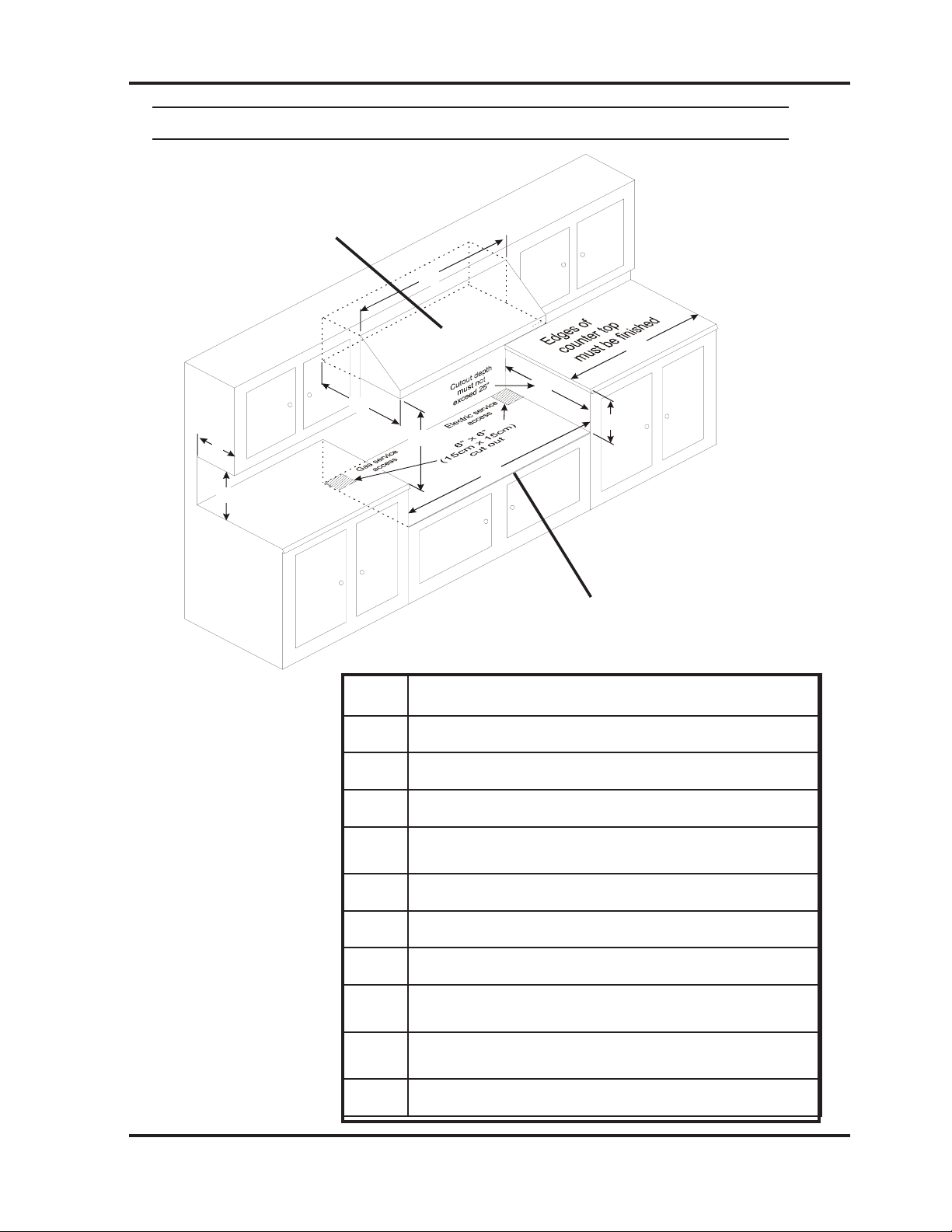
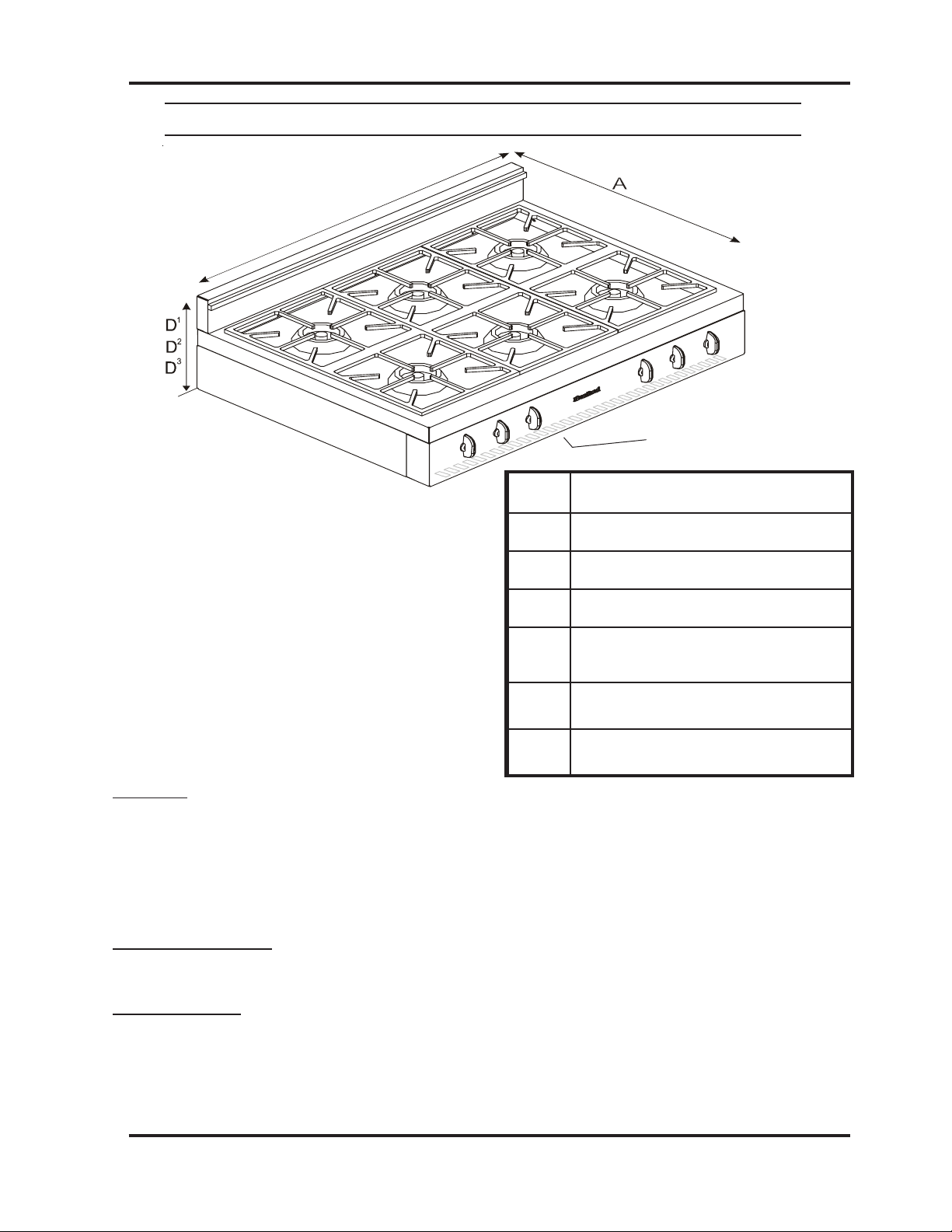
Installation Diagram- 30” Legend Cooktop Model 3800
A
B
C
D
1
2
3
D
D
Air intake slots on underside of control panel
must not be obstructed
or covered.
Figure 1
Dim 30” Legend Cooktop
A 26 5/8” (68cm)
B 8 1/4” (21cm)
C 29 3/4” (76 cm)
1
D
2
D
3
D
Standard prole:14 1/4”(36.2 cm) (as shown in diagram)
low prole: 10 1/8” (26 cm)
high back w/ shelf: 28 1/4” (72cm)
Table 1
Clearances
• Minimum distance between the cooktop and a side wall above the cooktop surface is 6”
(see dim “J” in Table 2 on next page)
• Depth of cutout must not exceed 25”. (see dimension G) Air intake slots on underside of control panel
must not be obstructed or covered.
Electrical requirements:
• Electrical hookup must be done by a licenced electrician
• 120 Volts 60Hz .375 kW 3 prong plug 5 ft-(1.5 m) power cord included.
Gas Requirements:
• Gas hook-up must be done by a licensed gas tter.
• Pressure requirements: Natural gas: 6” W.C. (min); LP gas: 11” W.C. (min)
• Connection: 1/2” NPT
• An accessible manual shut off valve must be installed at the appliance.
• Note: This unit contains a pre-set regulator
• Natural Gas/Propane Conversion kits are available - must be done by a licensed gas tter
6
Page 7
I
J
K
O
N N
1 2
M
G
H
L
Clearance Diagram- 30” Legend Cooktop Model 3800
An appropriate exhaust hood with a minimum of
450 CFM is required on all 30” Legend cooktops to ensure adequate and proper ventilation.
For superior ventilation we recommend using a
36” hood, however a 30” hood is adequate.
Note: Support deck must be able
to support a total weight of 4 burner
model: 175 lbs
Figure 2
Dim 30” Legend Cooktop
Note: If cooktop must stand beside a
refrigerator, it is important for proper
air circulation that there be at least
5” (13 cm) of space between the two
appliances.
G Maximum 25” (63.5cm)
H Maximum 7 3/4” (21cm)
I 30” (77 cm)
J Minimum 6” (16cm) left and right side
K 13”(33cm)
L Specify Width of Hood
M 24” (61cm)
1
N
2
N
30” min to 36” max (76.2-92cm) for standard and high back guard
30” min to 32 “max (76.2-82cm) for low prole back guard
Table 2
O 18” (46cm)
7
Page 8
B
C
Installation Diagram- 36” Legend Cooktop Model 3820
Air intake slots on underside
of control panel must not be
obstructed or covered.
Figure 1
Table 1
Clearances
• Minimum distance between the cooktop and a side wall above the cooktop surface is 6” (see dim “J in Table 2 on next
page)
• 0” Clearance to the back of the cooktop may be obtained when installing the appliance against a non-combustible wall
or with the installation of our Splashback Kit. Responsibility for ensuring that the rear wall is non-combustible lies with
the owner or end user. (check local building codes) - if wall behind cooktop is deemed combustible and our splashback
kit is not installed, then the minimum spacing from the back of stove to nearest combustible wall is 6”• Depth of cutout
must not exceed 25”. (see dimension G) Air intake slots on underside of control panel must not be obstructed or covered.
Dim 36” Legend Cooktop
A 26 5/8” (68cm)
B 8 1/4” (21cm)
C 36” (92cm)
1
D
2
D
3
D
Standard prole:14 1/4” (36.2cm) (as
shown in diagram)
low prole: 10 1/8” (26 cm)
high back w/ shelf: 28 1/4” (72cm)
Electrical requirements:
• Electrical hookup must be done by a licenced electrician
• 120 Volts 60Hz .375 kW 3 prong plug 5 ft-(1.5 m) power cord included.
Gas Requirements:
• Gas hook-up must be done by a licensed gas tter.
• Pressure requirements: Natural gas: 6” W.C. (min); LP gas: 11” W.C. (min)
• Connection: 1/2” NPT
• An accessible manual shut off valve must be installed at the appliance.
• Note: This unit contains a pre-set regulator.
• Natural Gas/Propane Conversion kits are available - must be done by a licensed gas tter
8
Page 9

I
J
K
O
N N
1 2
M
G
H
L
Clearance Diagram- 36” Legend Cooktop Model 3820
An appropriate exhaust hood with a minimum of
900 CFM is required on all 36” Legend cooktops to ensure adequate and proper ventilation.
For superior ventilation we recommend using a
42” hood, however a 36” hood is adequate.
Note: Support deck must be able to support
a total weight of Grill model : 200 lbs 6 burner
model: 220 lbs
Dim 36” Legend Cooktop
Figure 2
Note: If cooktop must stand beside a refrigerator, it is
important for proper air circulation that there be at least 5”
(13 cm) of space between the two appliances.
Table 2
G Maximum 25” (63.5cm)
H Maximum 7 3/4” (21cm)
I 36 1/4” (92cm)
J Minimum 6” (15.2cm) left and right side
K 13”(33cm)
L Specify Width of Hood\
M 24” (61cm)
1
N
2
N
30” min to 36” max (76.2-92cm) for standard
and high back guard
30” min to 32” max (76.2-82cm) for low pro-
le back guard
O 18” (46cm)
9
Page 10

Exhaust Hood
An exhaust hood must be installed over your
new appliance. (see g. 2) Exhaust hoods
to match the Legend cooktops are available
from your dealer. Our hoods are designed
and built to complement your range’s visual
appeal and performance.
Models 3800/3820 gas cooktops must be
electrically grounded in compliance with local codes. In the absence of local codes, the
installation must conform with the National
Electrical Code.
Disconnect the electrical supply and turn off
the gas supply before servicing the appliance.
Should you wish to install an exhaust hood
of your own choice, ensure that the exhaust
hood you purchase is the correct size and
capacity for your Heartland cooktop. Please
follow the exhaust hood manufacturers installation instructions. When installing an after
market exhaust hood over a Heartland cooktop we recommend that you use the clearances as shown in the clearance diagrams for
exhaust hood installations. See page 3-10.
Venting Safety Guidelines:
Installation must be completed in accordance with all local and national codes. Use
only materials which conform to local codes
in effect. Be sure the power is disconnected
before doing any electrical work. All duct
work must be metal. Do not use plastic duct.
The hood should never be exhausted into a
wall cavity or an attic where an accumulation
of grease could become a re hazard. When
the installation is completed, turn on the fan
and make sure that there are no obstructions
in the line.
Electrical Installation
Electrical requirements: standard 120 volts
60 Hz .375 Kw volt receptacle, properly polarized, on it’s own line. Cooktops are
supplied with a 3 prong 5 ft. (1.5 m) moulded
plug cap power cord.
Gas Line Installation
Gas requirements: 30” and 36” Heartland gas
cooktop models can be operated with either
natural gas or liquid propane (LP). The cooktops are set for either natural gas OR propane at the factory. A conversion kit may be
purchased at a later time and installed on site
should the need arise. The cooktop requires a
½” NPT connector. Use minimum 5/8” diam-
eter exible line. Note: This unit contains a
pre-set regulator.
The cooktop must be installed in compliance
with local codes. In the absence of local
requirements, the installation must conform
with the National Gas Code.
Note: Appliances installed in the state of Massachusetts:
- This appliance can only be installed in the state of Massachusetts
by a Massachusetts licensed plumber or gas tter
-This appliance must be installed with a three (3) foot / 36 inch
long exible gas connector
-A “T” handle type manual gas valve must be installed in the
gas supply line to this appliance
During any pressure testing of the gas supply piping system, at test pressures equal to
or less than 2.5 KPS, the cooktop must be
isolated from the gas supply piping system by
closing its individual manual shutoff valve.
The maximum propane/natural gas supply inlet pressure must not exceed 14” of water column. The minimum gas supply inlet should
be at least 6” of water column for natural gas
or at least 11” of water column for LP gas.
10
Page 11

Preparing the Cooktop for
Cut-out
handles
Cooktop
Installation
1. Carefully remove banding with metal
shears. Caution: banding may be under
pressure, wear gloves to protect hands
from accidental cuts.
2. Remove cardboard lid.
3. On 30” models there are 2 individual
boxed grates. Remove from packaging
and inspect the grates for any damage to
the nish. 36” models have 3 individual boxed grates. 36” grill models have 2
grates.
8. Assemble the backguard. (See g. 4)
Locate the backguard at the back of the cooktop. Remove screws and backguard. Do not
throw these screws away. They are required
to reinstall the backguard. Line up holes in
the backguard with the holes in the back of
the cooktop.
Cooktop Backguard Assemble
(g. 4)
4. Remove remaining styrofoam packaging and the 4 corner pieces.
Removing Cooktop from Packaging:
(g. 3)
5. With TWO people, carefuly lift the cooktop top from the box using the cardboard
support with the cut-out handles for lifting.
(See g. 3)
9. If you are installing a 20” high prole
backguard:
a. Unpackage.
b. Secure 20” high prole back to the stove
top using:
3-large metal washers.
3-small metal washers.
3-stainless steel screws.
c. Secure back panel to the 20” high prole
back using:
9-black sheet metal screws.(do not secure
the three bottom holes at this time)
6. Place cooktop on a solid table for
removal of plastic bag and a nal inspection
of product.
7. Check each burner to ensure that
during shipping the burner pieces have not
become dislodged from their proper position.
See page 20 for proper positioning.
d. Secure brackets (#3266-3 pcs.)to the
20” high prole back and stove top,using 6
black sheet metal screws.
10. Cooktop is now ready for gas connec-
tion by a qualied installer.
11
Page 12

Cooking Controls
A
B
The cooking controls are located on the front of the cooktop. These controls offer an innite
number of heat settings for ease and accuracy in cooking. They have a range from 15,500 BTU
(setting #5) to as low as 450 BTU (setting #1) Refer to page 14 (g.6) or page 17 (g.7) for
details.
Cooktop Features
B. Gas burner controls allow for an
A. Burners feature 15,500 BTU (4.4kW)
easy clean, sealed style, dual head burners.
The outer head is designed for high temperature, heavy duty jobs. The inner head is more
suited for low temperature requirements, such
as sauces and melting chocolate. Output is
adjustable to as low as 450 BTU.
innite selection of cooking temperatures.
Push and turn style controls are positioned
at the front of the cooktop for easy access.
All models feature “auto-reignition”. Should
the ame go out for any reason, the igniter
automatically begins to spark to reignite the
burner.
Cooking Controls
(g 5)
12
Page 13

Control Panel Graphic
(g 6)
These illustrations show the control panel layout of each model.
4 burner
6 burner
13
Page 14

Burner and Grill Operation
Lighting the Top Burners
Cooktop is equipped with a spark ignition
system that is electrically operated. Pushing
in and turning the knob to any position will
light the burner. When the knob is turned, a
distinct clicking noise will be heard. After
the burner lights, the clicking noise will stop.
Note: When lighting any one burner, all
burners will spark, but only the burner
selected will light. All models feature “auto-
reignition” – should the ame go out for any
reason, the igniter automatically begins to
spark to re-ignite the burner. See “Reference” section for manual lighting
procedure.
Propane Stoves: a slight pop or ash may
occur at the burner ports for a few seconds
after the burner has been turned off. This
“extinction pop” is normal for propane gas.
Note: Incorrect burner alignment will produce
a potentially dangerous ame and poor burner
performance. (refer to g 11)
Small Pot Ring / Trivet
Pot ring support is used when cooking on top
burners while using a small pot. The trivet
ts on any burner. Each channel ts on one
of 4 ngers on the burner grate. (see g 8 )
(g 8)
This channel ts on a nger
on the burner grate.
Dials
30” - left rear burnerl
(g 7)
14
Page 15

Care and Cleaning
Porcelain – Legend Series
Keeping it clean
The porcelain is very serviceable and simple
to clean, but because it is glass, it will not
withstand rough handling or abuse. Never
place a cold wet cloth on a hot porcelain surface. Porcelain is glass and sudden changes
in temperature may cause cracking. To clean
porcelain surfaces, use warm, soapy water,
glass cleaner or non abrasive cleaner and a
soft cloth. Avoid abrasive cleaners.
If any acid based food or liquid, such as
lemon juice or tomato juice, is spilled on the
cooktop, wipe it at once to prevent staining.
Depending on level of acidity, some minor
discoloration may occur.
15
Page 16

Surface Burners
Important: tab must
be locked in position
on the burner base.
Inner burner head
Outer burner head
Burner ring
Cross ring - brass
Burner base
Nickel Plated Parts
Top burners require little care other than to
wipe off the head of each burner. If a boil
over occurs, the burner part can be easily
lifted out so burner port holes can be cleaned
in hot soapy water with a soft brush. There
are no bolts or screws to remove. The igniter must also be kept clean to ensure quick
positive starts. For normal or everyday
cleaning of light spills, wipe the burner parts
with a damp cloth. For heavy duty cleaning—cooked spills, oil stains, etc., scrub with
a tub and tile type of cleaner. Rinse thoroughly after every cleaning operation. Wipe
away excess water . Avoid using abrasives on
the burner base, as they may damage the nish. Remove all water from the burner ports
before lighting the burner (water in ports will
lead to random sparking)
Note: When replacing, be sure the tab is
locked securely in position on the burner base
otherwise random sparking and uneven ame
will occur. (g 9)
These may be cleaned with any non abrasive
chrome and metal polish or Windex and a soft
cloth. If any acid based food or liquid, such
as lemon juice or tomato juice, is spilled on
the cooktop, wipe it at once to prevent staining.
Surface Burner
(g 9)
16
Page 17

Trouble Shooting
Burner Set Up and Adjustment
The cooktop was carefully set up and inspect-
ed at the factory but some nal adjustments
may be necessary once the unit is installed.
Important: ensure burner rings are assembled properly
1. First, check to ensure there are no gas
leaks. Propane and natural gas have a very
distinct odour which is easily detected by the
human nose. If in doubt, soak each pipe joint
with soapy water and look for bubbles. Do
not use an open ame for testing.
2. Check that all controls are operating
properly by lighting each of the burners.
Turn the burners on by pushing in and
turning counter clockwise. Test them on low,
medium, and high settings.
3. Check the quality of the ame. The
burners should have a steady, relatively quiet
ame with a ½” (13mm) sharp blue inner
cone. There should be no yellow ame. The
outer ame should have a 2 ½” (64mm) sharp
blue cone. (see g 11)
If random sparking occurs after the
burner lights or there is uneven ame from
the burner or there is a ame from under the
burner trim ring, (see g 11) the cause is the
brass burner ring is not properly positioned
on the burner base. Please refer to page 16
for proper burner assembly . Some ticking is
normal from time to time.
You should now be “cooking with gas”. If
not, refer to the gas trouble shooting section
later in this manual.
Outer cone
Inner cone
Proper Flame
Improper Flame
Flames uneven
(g 11)
Flame
present
under burner
ring.
17
Page 18

Power Failure Operation
Gas Trouble Shooting
Electricity to the cooktop only powers the
auto ignition. If electrical power is interrupted, meals can still be cooked on the top
burners of your cooktop. Follow these simple
directions to manually light the burners.
Caution: Make sure your hands and clothing
are clear of the burner when lighting it!
Manually Lighting the Burners
1. Remove cast grate, for unobstructed access to the burner head.
2. Hold a ame source to the outside
burner head. We recommend a barbe-
cue lighter as a ame source (see g. 9)
3. Push in and turn the corresponding control knob to the medium setting.
4. After the burner lights, adjust ame size
as required.
5. Carefully replace cast grate. Keep ngers clear of the ame.
Do not attempt to light front burner by us-
ing the lit back burner.
If you smell gas:
Finding a gas leak is not a “do it yourself”
procedure. If you smell gas, turn off the supply of gas to the range and call for service.
If you have other problems:
Before any component is replaced, follow this
four-step check list. Then consult “Gas
Trouble Shooting Chart” on the next page.
1. Be sure problem is not due to improper
operation.
2. Check basic adjustments – correct
pressure, dirt in the line, etc.
3. Ensure correct gas setting used. Setting
should be set for either propane or
natural gas.
4. If gas pressure and all adjustments seem
correct, use the following chart to help
identify the problem and/or malfunctioning component.
Please note that the “auto reignition” feature
will not function without electricity.
If you still require help...
If you still require help...
If you still require help...
Contact your dealer and/or service techni-
Contact your dealer and/or service techni-
Contact your dealer and/or service technician. Should you still require help, see
cian. Should you still require help, see
cian. Should you still require help, see
the “Reference” section on how to contact
the “Reference” section on how to contact
the “Reference” section on how to contact
Heartland Appliances.
Heartland Appliances.
Heartland Appliances.
18
Page 19

Gas Trouble Shooting Chart
Problem Cause Remedy
No sparks when any control
knob is turned to “light”
No sparks when one or some
control knob(s) is (are) turned
to “light”
Sparking occurs at electrodes
when all control knobs are
turned off
No power to spark module - module
switch faulty
Re-ignition electrode controlled by
knob switch is grounded or has a high
resistance leak
Disconnected switch lead or short in
switch lead
High resistance or open connection
between spark output terminal and
H.V. wire receptacle (spark will jump
small gap but sensing current will not)
Check electrical supply to spark
module with voltmeter - replace
module
Check high voltage wires care-
fully for loose connections or
pinches in the wires; if con-
nections are tight, replace high
voltage wire
Check all switch lead connec-
tions for looseness and wires for
damage
Push receptacles rmly onto all
terminals
Check positioning of shrink
sleeving on receptacle – should
be ush with end of receptacle
– trim if necessary
All burners that are turned on
have lighted but electrodes are
still sparking
Flame jetting off outer head
burner ring or inner head
burner ring
Nuisance sparking when one
or both grill burners are on
Nuisance sparking Burners not properly assembled
Defective module Replace module
Ground/Earth lead to module discon-
nected or cooktop chassis not properly
connected to ground/earth by ground/
earth lead or through third prong of
power cord plug, combined with re-
versed power supply polarity
Too much air
Pots too large
Too much air
Pots too large
Check ground/earth connection
of range chassis and ground/
earth lead connection to module
Reduce size of air shutter open-
ing until ame is no longer jetting
off burner head
Reduce size of air shutter open-
ing until ame is no longer jetting
off burner head.(Flame jetting off
burner)
Re-assemble burners ensuring
notches line up with groves
19
Page 20

Reference
Accessories
Wok Ring #3389
Stainless steel 9” diameter ring manufactured
to t standard size woks. The wok ring is
designed to t into the grate ngers of the
Legend series ranges. (g 11)
(g 11)
Legend Griddle Kit #3809
Support is stainless steel for long lasting and
easy clean up. The griddle plate is ribbed on
one side for grilling and holds excess grease
while cooking. Flat side of griddle plate
suited for pancakes and similar foods. (g 12)
Propane/NaturalGas Conversion
Kits and Information
The Legend ranges are ordered from the factory pre-set for either natural gas or propane.
They can be converted after installation by
converting the pressure regulator and replac-
ing the orices in the valves and burners with
the appropriate orice kit.
How to order conversion kits:
Kits can be ordered from your dealer or directly from Heartland Appliances. For more
information please call our order desk:
(519) 650-5775 or Fax (519) 650-3773.
Note: Gas conversions must be performed by
a qualied gas technician.
If you still require help...
Heartland Ranges contain standard electrical
components available from your dealer or
Heartland Appliance.
(g 12)
Splashback kit #3801 (30”) & #3802 (36”)
Spashback kit required for models with 0”
clearance to combustible rear walls. coloured
porcelain panels for Legend series. Kit also
includes two warming racks which mount 20”
above the stove top on the splashback.
In case repair is required, consult your dealer
for an appliance repair depot near you. For war-
ranty service, please call your dealer rst or call
Heartland, if necessary.
Business (519) 650-5775 Fax (519) 650-3773
Toll Free Telephone 1-800-361-1517
Toll Free Fax 1-800-327-5609
Have your serial number, model, and date of
purchase information ready. Without this information, service response may be delayed and
replacement parts or diagnosis may be incorrect.
For warranty coverage, see warranty statement.
20
Page 21

Parts Drawing & Description
3360
3362
3699
3663
3661
3665 3680
3483
3486
3484
3364
3457
3350
(g 12)
3350 Double cast grate
3364 Grill
3457 Small pot ring
3483 Chrome Control knob
3484 Commercial Knob - Black- W/Screening
3486 Commercial Knob Chrome Bezel
3660 Dual burner inner head D - black
3661 Dual burner inner base D - brass
3662 Dual burner outer head D - black
3663 D Dual Burner cross ring - brass
3699 Dual burner trim ring D - black
3665 D Dual burner outer base
3680 Electrode C/W 900 mm lead
21
Page 22

Safety Guidelines
For a more comprehensive list of safety guidelines and precautions please refer to Appendix
A: Safety Precautions.
Important Safety Instructions
1. Proper Installation - Be sure your appliance is properly installed and grounded
by a qualied technician.
2. Never use appliance for warming or
heating the room.
3. Children should not be left alone or
unattended in area where appliance is in
use. They should never be allowed to
sit or stand on any part of the appliance.
4. Wear proper apparel – loose tting or
hanging garments should never be worn
while using the appliance.
5. User servicing – do not replace any
part of the appliance unless specically
recommended in the manual. All other
servicing should be referred to a quali-
ed technician.
Exhaust Hood Safety
Caution: Do not store items of interest to
children in cabinet above the cooktop or on
top of cooktop cabinet. Children climbing
on cooktop to reach items could be seriously
injured.
1. Clean exhaust hood frequently – grease
should not be allowed to accumulate
on hood or lter. See “Hood Operation
Instructions” for more details.
2. When aming foods under the hood,
turn the fan off. An operating fan may
spread the ame.
6. Storage on appliance – ammable ma-
terials should not be stored on or near
surface units.
7. Do not use water on grease res –
smother re or ame or use dry chemi-
cal or foam-type extinguisher.
8. Use only dry potholders – moist or
damp potholders on hot surfaces may
result in burns from steam. Do not let
potholder touch hot heating elements.
Do not use a towel or other bulky cloth.
22
Page 23

Selecting the Proper Cookware
Utensils will affect the overall safety and
performance of cooktop cooking. It is important to select them carefully. An improperly
selected utensil will not cook efciently or
evenly. For best results, follow these guidelines:
1. Use medium to heavy gauge metal
cookware with at and smooth bottoms
for greatest efciency. Aluminum and
sandwich stainless steel utensils conduct
heat quickly. Cast iron and especially
glass or ceramic cookware are slower
to heat. Glass or ceramic cookware
should only be used as recommended
by the cookware manufacturer.
2. Avoid using pots and pans with rounded
(concave or convex) or uneven bottoms,
or cookware that warps under heating.
The bottom of the utensil should touch
all grate support ngers evenly. Utensil
atness can also be checked by plac-
ing a straight edge (ruler) against the
bottom of the cooking vessel. There
should be no gap between the straight
edge and the utensil bottom. Utensils,
whether full or empty, should never
rock on the grates. A rounded utensil is
more unstable and may cause scorching
or burning of food due to uneven heating.
4. Use utensils with tight tting lids to
retain heat, odors, and steam. Lids also
enable food to be prepared with less
water, thereby retaining the vitamin
content.
5. Use cooking vessels that are clean and
dry.
Important
• Do not use undersized utensils with
unbalanced handles. These can tip easily. See “Burner and Grill Operation”
section for information on small pot
support ring (trivet).
• Use of utensils having rough bottoms
can result in permanent damage to the
top edges of the porcelainized grates.
• Large utensils may cause burner
ames to spread and curve around
edge of utensil. Turn heat down to
reduce ames.
• Large utensils may cause ames to be
smothered and result in reignition to
commence. Do not use these utensils
if ames utter and escape burners.
We recommend pots no larger than
11”
3. Match the utensil to the cooking process. Best cooking results are usually
achieved when utensils are nearly full.
Choose the utensil size accordingly.
Specialty cookware such as woks, pressure cookers, canning madules, and
deep fat fryers must be carefully chosen to ensure that they meet all safety
guidelines contained in this manual.
23
Page 24

Safety Precautions
• Set the burner control so that the ame
heats only the bottom of the pan and does
not extend beyond the bottom of the pan.
Excessive ame is hazardous. The high BTU
burners can easily melt cookware handles.
• Hold the handle of the pan, using a dry
potholder, to prevent movement of the uten-
sil when stirring or turning food.
• Always heat fat slowly, and watch as it
heats.
• Never leave the burners unattended at high
ame settings. Boilovers cause smoking and
greasy spillovers that may catch on re. If
the burner ames are smothered by a severe
boilover, which affects the igniter, unburned
gas will escape into the room.
• Do not let pot holders come near open
ames when lifting cookware. Do not use
a towel or other bulky cloth in place of a pot
holder.
• To minimize the possibility of burns, igni-
tion of ammable materials and spillage, turn
cookware handles toward the side or back of
the cooktop without extending over adjacent
burners.
• Foods for frying should be as dry as pos-
sible. Frost on frozen food or moisture on
fresh foods can cause hot fat to bubble up and
over the sides of the pan.
• Use the least possible amount of fat for
effective shallow or deep fat frying. Fill-
ing the pan too full of fat can cause spillovers
when food is added.
• Use a deep fat thermometer whenever pos-
sible to prevent overheating fat beyond the
smoking point.
• Never try to move a pan of hot fat. Wait
until the fat is cool.
• When using glass cookware, make sure it is
designed for cooktop use.
• If a combination of oils or fats will be used
in frying, stir together before heating or as
fats melt slowly.
• Do not leave any items on the cooktop. The
hot air from the vent may ignite ammable
items and will increase pressure in closed
containers, which may cause them to burst.
• Keep all plastics away from the burners.
• Never block the vents (air openings) of the
cooktop. They provide the air inlet and outlet
that are necessary for the cooktop to operate
properly with correct combustion. Air openings are located on the bottom of the front
control panel.
• Always turn the burners to OFF before
removing cookware.
• Carefully watch foods being fried at a high
ame setting.
• Do not leave plastic items on the cooktop
– they may melt if left too close to the vent.
• To avoid the possibility of a burn, always
be certain that the controls for all burners are
at the OFF position and all grates are cool
before attempting to remove them.
• When aming foods are under the hood,
turn the fan off. The fan, if operating, may
spread the ames.
CON’T
24
Page 25

• Grease is ammable. Let hot grease cool
before attempting to handle it. Avoid letting
grease deposits collect in the container under
the cooktop burners or the grill. Clean these
areas after each use or boilover.
• For proper lighting and performance of
the burners keep the burner ports clean. It
may be necessary to clean these when there is
a boilover or when the burner does not light,
even though the electronic ignitors click.
• Clean the cooktop with caution. Avoid
steam burns; do not use a wet sponge or cloth
to clean the cooktop while it is hot. Some
cleaners produce noxious fumes if applied to
a hot surface. Follow manufacturer’s
directions.
• Do not use the grill for cooking excessively
fatty meats or products which promote
are-up.
• DO NOT use cookware on the grill.
• If cooktop is located near a window, do not
hang long curtains that could blow over the
burners and create a re hazard.
• Be sure all the controls are turned off
and the appliance is cool before using any
type of aerosol cleaner or cooking spray on
or around the appliance. The chemical that
produces the spraying action could, in the
presence of heat, ignite or cause metal parts
to corrode.
25
Page 26

See our complete line of kitchen appliances:
3010- 30” Classic II Series Refrigerator, 18 cubic
feet capacity, bottom mount freezer drawer, and
convienient top mount fresh food compartment. Ice
maker is available as an option. The Classic series
also offers an optional Cowl. Energy efciency
rating 548 kwh/year. Also available in Legend 3060
models.
3110- 36” Classic II Series Refrigerator, 22 cubic feet
capacity, top mount freezer, counter depth design. Ice
maker is standard. The Classic series also offers an
optional Cowl. Energy efciency rating 552 kwh/year.
Also available in Legend 3160 models.
3530- Legend Gas / Electric kitchen range - 4 sealed
gas burners, electric convection oven ts in a 30”
opening! Cooktop versions for Legend 3800 models
are available.
3630- Legend 36” Gas / Electric kitchen range - 6
sealed gas burners or 4 sealed burners and centre
grill! Electric convection oven come standard.
Cooktop versions for Legend 3820 models are
available.
Model 3115:
shown with the
Optional c owl
(ava ila ble onl y
with the Classic
Series)
5200- 48” Gas / Electric kitchen range- 6 sealed
gas burners, electric convection oven, dual fuel!
Also available with the convenience of a self clean
oven, as model 5210
9800 (Built-in)- 30” wall oven can be also be
installed undercounter with cooktop. Includes selfclean feature.
4200- 30” Gas / Electric kitchen range - 4 sealed
gas burners, electric convection oven ts in a 30”
opening! Also available with a self clean oven
feature, as model 4210
Model 1902
6200- 48” Electric kitchen range- 5 solid element
burners, convection oven. Also available with the
convenience of a self clean oven, as model 6210
8200- 30” Electric kitchen range- 4 solid element
burners, convection oven ts in a 30” opening! Also
available with a self clean oven feature, as model
8210
7200- 48” Gas or propane kitchen range - 6 sealed
gas burners, a chef’s dream come true!
9200- 30” Gas or propane kitchen range - 4 sealed
gas burners, ts in a 30” opening!
1900 (Oval)- Wood burning cookstove-old fashioned
cooking available in two models
2600 (SweetHeart)- Wood burning cookstove-same
as the Oval, in a smaller version!
For more information please call your dealer, or call
Heartland Appliances:
Phone 1-800-361-1517 or Fax 1-800-327-5609
26
 Loading...