

Taylor Freezers C717 User Manual

OPERATOR’S
MANUAL
Model C709 and C717
Blade Style Beater
Heat Treatment Soft Serve Freezers
Original Operating Instructions
083129-M
9/30/14 (Original Publication)
(Updated 11/8/2019)

Complete this page for quick reference when service is required:
Taylor distributor: __________________________________________________________
Address:_________________________________________________________________
Phone: __________________________________________________________________
Service: _________________________________________________________________
Parts: ___________________________________________________________________
Date of installation:_________________________________________________________
Information found on the data label:
Model Number:____________________________________________________________
Serial Number: ____________________________________________________________
Electrical Specs: Voltage__________________ Cycle__________
Phase__________________________________
Maximum Fuse Size: ______________________________________________________ A
Minimum Wire Ampacity: ___________________________________________________A
Note: Continuing research results in steady improvements; therefore, infor mation in this manual is subject to change
without notice.
Note: Only instructions originating from the factory or its authorized translation representative(s) are considered to be
the original set of instructions.
© 2014 Taylor Company
083129-M
Any unauthorized reproduction, disclosure, or distribution of copies by any person of an y portion of this wo rk may be
a violation of copyright law of the United States of America and other countries, could result in the awarding of
statutory damages of up to $250,000 (17 USC 504) for infringement, and may result in further civil and criminal
penalties. All rights reserved.
Taylor Company
750 N. Blackhawk Blvd.
Rockton, IL 61072

Section 1: To the Installer
Installer Safety . . . . . . . . . . . . . . . . . . . . . . . . . . . . . . . . . . . . . . . . . . . . . . . . . . . . . . .1-1
Site Preparation . . . . . . . . . . . . . . . . . . . . . . . . . . . . . . . . . . . . . . . . . . . . . . . . . . . . . .1-1
Air-Cooled Machines. . . . . . . . . . . . . . . . . . . . . . . . . . . . . . . . . . . . . . . . . . . . . . . . . . .1-2
Water Connections . . . . . . . . . . . . . . . . . . . . . . . . . . . . . . . . . . . . . . . . . . . . . . . . . . . .1-2
Electrical Connections. . . . . . . . . . . . . . . . . . . . . . . . . . . . . . . . . . . . . . . . . . . . . . . . . .1-2
Beater Rotation. . . . . . . . . . . . . . . . . . . . . . . . . . . . . . . . . . . . . . . . . . . . . . . . . . . . . . .1-3
Refrigerant . . . . . . . . . . . . . . . . . . . . . . . . . . . . . . . . . . . . . . . . . . . . . . . . . . . . . . . . . .1-3
Section 2: To the Operator
Section 3: Safety
Section 4: Operator Parts Identification
Model C709. . . . . . . . . . . . . . . . . . . . . . . . . . . . . . . . . . . . . . . . . . . . . . . . . . . . . . . . . .4-1
Model C717. . . . . . . . . . . . . . . . . . . . . . . . . . . . . . . . . . . . . . . . . . . . . . . . . . . . . . . . . .4-3
Model C709 Single-Spout Door and Beater Assembly. . . . . . . . . . . . . . . . . . . . . . . . .4-5
Model C717 Three-Spout Door and Beater Assembly . . . . . . . . . . . . . . . . . . . . . . . . .4-6
Feed Tube Assembly . . . . . . . . . . . . . . . . . . . . . . . . . . . . . . . . . . . . . . . . . . . . . . . . . .4-7
Accessories. . . . . . . . . . . . . . . . . . . . . . . . . . . . . . . . . . . . . . . . . . . . . . . . . . . . . . . . . .4-8
Brushes. . . . . . . . . . . . . . . . . . . . . . . . . . . . . . . . . . . . . . . . . . . . . . . . . . . . . . . . . . . . .4-9
Table of Contents
Section 5: User Interface
Symbol Definitions . . . . . . . . . . . . . . . . . . . . . . . . . . . . . . . . . . . . . . . . . . . . . . . . . . . .5-2
Feed Tube Assembly . . . . . . . . . . . . . . . . . . . . . . . . . . . . . . . . . . . . . . . . . . . . . . . . . .5-4
Operating Screen Descriptions. . . . . . . . . . . . . . . . . . . . . . . . . . . . . . . . . . . . . . . . . . .5-4
Freezer Locks . . . . . . . . . . . . . . . . . . . . . . . . . . . . . . . . . . . . . . . . . . . . . . . . . . . . . . . .5-7
Manager's Menu . . . . . . . . . . . . . . . . . . . . . . . . . . . . . . . . . . . . . . . . . . . . . . . . . . . . . .5-9
Fault Description. . . . . . . . . . . . . . . . . . . . . . . . . . . . . . . . . . . . . . . . . . . . . . . . . . . . .5-13
System Information. . . . . . . . . . . . . . . . . . . . . . . . . . . . . . . . . . . . . . . . . . . . . . . . . . .5-16
083129-M i

Table of Contents
Section 6: Operating Procedures
Freezing Cylinder Assembly. . . . . . . . . . . . . . . . . . . . . . . . . . . . . . . . . . . . . . . . . . . . . 6-1
Freezer Door Assembly . . . . . . . . . . . . . . . . . . . . . . . . . . . . . . . . . . . . . . . . . . . . . . . . 6-3
Feed Tube Assembly . . . . . . . . . . . . . . . . . . . . . . . . . . . . . . . . . . . . . . . . . . . . . . . . . . 6-6
Install Drip Pans and Splash Shield . . . . . . . . . . . . . . . . . . . . . . . . . . . . . . . . . . . . . . . 6-7
Sanitizing . . . . . . . . . . . . . . . . . . . . . . . . . . . . . . . . . . . . . . . . . . . . . . . . . . . . . . . . . . .6-7
Priming . . . . . . . . . . . . . . . . . . . . . . . . . . . . . . . . . . . . . . . . . . . . . . . . . . . . . . . . . . . . .6-9
Daily Closing Procedures . . . . . . . . . . . . . . . . . . . . . . . . . . . . . . . . . . . . . . . . . . . . . . . 6-9
Daily Opening Procedures . . . . . . . . . . . . . . . . . . . . . . . . . . . . . . . . . . . . . . . . . . . . . 6-11
Setting Up. . . . . . . . . . . . . . . . . . . . . . . . . . . . . . . . . . . . . . . . . . . . . . . . . . . . . . . . . . 6-11
Manual Brush-Cleaning . . . . . . . . . . . . . . . . . . . . . . . . . . . . . . . . . . . . . . . . . . . . . . . 6-12
Draining Product from the Freezing Cylinder . . . . . . . . . . . . . . . . . . . . . . . . . . . . . . . 6-12
Rinsing . . . . . . . . . . . . . . . . . . . . . . . . . . . . . . . . . . . . . . . . . . . . . . . . . . . . . . . . . . . . 6-12
Hopper Cleaning. . . . . . . . . . . . . . . . . . . . . . . . . . . . . . . . . . . . . . . . . . . . . . . . . . . . . 6-13
Disassembly . . . . . . . . . . . . . . . . . . . . . . . . . . . . . . . . . . . . . . . . . . . . . . . . . . . . . . . . 6-13
Brush-Cleaning. . . . . . . . . . . . . . . . . . . . . . . . . . . . . . . . . . . . . . . . . . . . . . . . . . . . . . 6-14
Section 7: Operator’s Checklist
During Brush-Cleaning and Sanitizing . . . . . . . . . . . . . . . . . . . . . . . . . . . . . . . . . . . . . 7-1
Troubleshooting Bacterial Count . . . . . . . . . . . . . . . . . . . . . . . . . . . . . . . . . . . . . . . . . 7-1
Regular Maintenance Checks. . . . . . . . . . . . . . . . . . . . . . . . . . . . . . . . . . . . . . . . . . . . 7-1
Winter Storage . . . . . . . . . . . . . . . . . . . . . . . . . . . . . . . . . . . . . . . . . . . . . . . . . . . . . . . 7-2
Section 8: Troubleshooting Guide
Section 9: Parts Replacement Schedule
Section 10: Limited Warranty on Equipment
Section 11: Limited Warranty on Parts
ii 083129-M
Section 1
The following information has been included in the
manual as safety and regulatory guidelines. For complete
installation instructions, please see the Installation
Checklist.
To the Installer
WARNING!
edges that can cause severe injuries.
This machine has many sharp
Installer Safety
IMPORTANT! In all areas of the world,
machines should be installed in
local codes. Please contact your local authorities if you
have any questions.
Care should be taken to ensure that all basic safety
actices are followed during the installation and
pr
servicing activities related to the installation and service
®
of Taylor
machines.
• Only Taylor service personnel should perform
llation, maintenance, and repairs on Taylor
insta
machines.
• Authorized service personnel should consult
OSHA Standard 29CFRI910.147 or the
applicable code of the local area for the industry
standards on lockout/tagout procedures before
beginning any installation or repairs.
• Authorized service personnel must ensure that
the proper personal protective equipment (PPE)
is available and worn when required during
installation and service.
• Authorized service personnel must remove all
metal jewelry, rings, and watches before
working on electrical equipment.
accordance with existing
Site Preparation
Review the area where the machine will be installed.
Make sure that all possible hazards to the installer, user,
and the machine have been addressed.
For Indoor Use Only:
operate indoors, under normal ambient temperatures of
70°F to
successfully performed in high ambient temperatures of
104°F (40°C) at reduced capacities.
installed in an area where a water jet or hose can be
use
the machine. Failure to follow this instruction may result
in electrocution.
location where its use and mai
trained personnel. Failure to comply may result in
personal injury.
75°F (21°C to 24°C). The machine has
WARNING! This
d. NEVER use a water jet or hose to rinse or clean
WARNING! Only
This machine is designed to
machine must NOT be
install this machine in a
ntenance is restricted to
1
Note: All re
Taylor service technician.
machine must be disconnected prior to performing any
stallation, maintenance, or repairs. Failure to follow this
in
instruction may result in personal injury or death from
electrical shock or hazardous moving parts, as well as
poor performance or damage to the machine.
To the Installer
pairs must be performed by an authorized
DANGER! T
he main power supply(s) to the
Models C709 & C717
CAUTION! This
a level surface to avoid the hazard of tipping. Extreme
e should be taken in moving this machine for any
car
reason. T wo or more per sons are required to safely move
this machine. Failure to comply may result in personal
injury or damage to the machine.
The authorized installer should inspect the machine and
omptly report any damage to the local authorized
pr
Taylor distributor.
machine must be installed on
1-1
TO THE INSTALLER
ALWAYS FOLLOW LOCAL HEALTH CODES.
This machine is made using USA sizes of hardware. All
metric conversions are approximate an d var y in size .
Air-Cooled Machines
Do not obstruct machine's air intake and discharge
openings.
C709: A
1
on both sides and 0.0 in. on the rear of the machine.
C717:
around all sides of the machine. Install the deflecto r
provided to prevent recirculation of warm air. This will
allow for adequate air flow across the condenser.
Failure to allow adequate clearance can reduce the
efrigeration capacity of the machine and possibly cause
r
permanent damage to the compressor.
minimum of 6 in. (152 mm) air space is required
A minimum of 3 in. (76 mm) air space is required
Water Connections
(Water-Cooled Machines Only)
An adequate cold water supply must be provided with a
h
and shutoff valve. On the underside of the base pan or
on the right side of the machine, two 3/8 in. IPS water
connections for inlet and outlet are provided for easy
hookup. Half-inch inside diameter water lines should be
connected to the machine. (Flexible lines are
recommended, if local codes permit.) Depending on local
water conditions, it may be advisable to install a water
strainer to prevent foreign substances from clogging the
machine's automatic water valve. There will be only one
water in and one water out connection. Do not install a
hand shutoff valve on the water out line! Water should
always flow in this order: first, through the automatic
water valve; second, through the condenser; and third,
through the outlet fitting to an open trap drain.
IMPORTANT! A ba
required on the incoming water connection side. Please
the applicable national, state, and local codes for
see
determining the proper configuration.
ckflow prevention device is
Electrical Connections
IMPORTANT! In the United States, this
machine is intended to be installed in accordance wit
the National Electrical Code (NEC), ANSI/NFPA 701987.
The purpose of the NEC code is the practical
safeguarding of persons and property from hazards
arising from the use of electricity. This code contains
provisions considered necessary for safety.
In all other areas of the world, the machine should be
installe
Please contact your local authorities if you have any
questions.
Each machine requires one power supply for each data
lab
machine for branch circuit overcurrent protection or fuse,
circuit ampacity, and other electrical specifications.
See the wiring diagram provided inside the electrical box
for
grounded. Failure to do so can result in severe personal
inju
provided with this machine. Some
grounding lug to be properly attached to the rear of the
frame by the authorized installer. The installation location
is marked by the equipotential bonding symbol (5021 of
IEC 60417-1) on both the removable panel and the
machine's frame.
d in accordance with the existing local codes.
el on the machine. Check the data label(s) on the
proper power connections.
WARNING! This machin
ry from electrical shock.
IMPORTANT! An eq
uipotential grounding lug is
e must be properly
countries require the
h
1-2
Models C709 & C717
To the Installer
IMPORTANT!
• Stationary machines which are not equipped
with a p
to disconnect the machine from the power
source must have an all-pole disconnecting
device with a contact gap of at least 0.125 in.
(3 mm) in the external installation.
• Machines that are permanently connected to
fixed wiring and for which leakage currents may
exceed 10 mA, particularly when disconnected
or not used for long periods, or during initial
installation, shall have protective devices to
protect against the leakage of current, such as a
GFI, installed by authorized personnel to local
codes.
• Supply cords used with this machine shall be
oil-resistant, sheathed flexible cable not lighter
than ordinary polychloroprene or other
equivalent synthetic elastomer-sheathed cord
(code designation 60245 IEC 57) installed with
the proper cord anchorage to relieve conductors
from strain, including twisting, at the terminals
and protect the insulation of the conductors from
abrasion.
If the supply cord is damaged, it must be replaced by a
Taylor serv
ower cord and a plug or another device
ice technician to avoid a hazard.
Beater Rotation
TO THE INSTALLER
Refrigerant
CAUTION! This machine contains fluorinated
greenhouse gases (F-Gas) to provide refrigeration using
rmetically sealed circuit or within foam insulation.
a he
This machine’s type of gas, quantity, Global Warming
Potential (GWP), and CO
is recorded on the machine’s data label. The refrigerant
used is generally considered nontoxic and
nonflammable. However any gas under pressure is
potentially hazardous and must be handled with caution.
NEVER fill any
Filling the cylinder to approximately 80% will allow for
normal expansion.
refrigerant cylinder completely with liquid.
CAUTION! Use on
listed on the machine's data label or authorized through a
nufacturer's technical bulletin. The use of any other
ma
refrigerant may expose users and operators to
unexpected safety hazards.
WARNING!
skin may cause serious damage to tissue. Keep eyes
d skin protected. If refrigerant burns should occur,
an
flush the area immediately with cold water. If burns are
severe, apply ice packs and contact a physician
immediately.
tonnes equivalent information
2
ly approved refrigerant
Refrigerant liquid sprayed onto the
1
NOTICE! Beater rotation must be clo ckwise as
viewed looking into the freezing cylinder.
To correct the rotation on a three-phase machine,
terchange any two incoming power supply lines at the
in
freezer main terminal block only. To correct rotation on a
single-phase machine, exchange leads inside the beater
motor. ( Follow the diagram printed on the motor.)
Electrical connections are made directly to the terminal
lock provided in the main control box, located behind
b
the service panel.
It is recommended that beater rotation adjustment be
erformed by an authorized Taylor service technician.
p
To the Installer
Models C709 & C717
NOTICE!
aware of and in compliance with local government laws
egarding refrigerant recovery, recycling, and reclaiming
r
systems. For information regarding applicable local laws,
please contact your local authorized Taylor distributor.
IMPORTANT! Refrig
associated lubricants may be extremely moisture
sorbent. When opening a refrigeration system, the
ab
maximum time the system is open must not exceed 15
minutes. Cap all open tubing to prevent humid ai r or
water from being absorbed by the oil.
Ta ylor reminds technicians to be
erants and their
1-3

TO THE INSTALLER
Notes:
1
1-4
Models C709 & C717
To the Installer
Section 2
Your machine has been carefully engineered and
manufactured to give you dependable operation. When
properly operated and cared for, it will produce a
consistent, quality product. Like all mechanical products,
cleaning and maintenance will be required. A minimum
amount of care and attention is nece ssary if the operating
procedures outlined in this manual are followed closely.
IMPORTANT! Th
before operating or performing any maintenance on the
chine.
ma
Your Taylor machine will NO
correct any errors made during setup or filling operations.
Thus, the initial assembly, setup, and priming procedures
are of extreme importance. It is strong ly re co mm e nd e d
that all personnel responsible for the machine's
operation, including assembly and disassembly, go
through these procedures together to be properly trained
and to make sure that all personnel understand their role
in using and maintaining the machine.
is manual should be read
T compensate for and/or
To the Operator
IMPORTANT! If th
symbol is affixed to this machine, it signifies
machine is compliant with the EU directives as well as
other similar end-of-life legislation in effect after August
13, 2005. Therefore, it must be collected separ ately after
its use is completed and cannot be disposed as unsorted
municipal waste.
The user is responsible for delivering the machine to the
appropriate collec
code.
For additional information rega
disposal laws, please contact the municipal waste facility
and/or local authorized Taylor distributor.
tion facility, as specified by your local
e crossed-out wheeled bin
that this
rding applicable local
2
If you require technical assista
local authorized Taylor distributor.
Note: Your Taylor warranty is valid only if parts are
authorized Taylor parts purchased from a local
authorized Taylor distributor, and only if all required
service work is provided by an authorized Taylor
service technician. Taylor Company reserves the
right to deny warranty claims on machines or parts if
Taylor-unapproved parts or incorrect refrigerant were
installed in the machine, system modifications were
performed beyond factory recommendations, or it is
determined that the failure was caused by abuse,
misuse, neglect, or failure to follow all operating
instructions. For full details of your Taylor warranty,
please see the Limited Warranty section in this manu al.
nce, please contact your
To the Operator
Models C709 & C717
2-1

TO THE OPERATOR
Compressor Warranty Disclaimer
The refrigeration compressor(s) on this machine are
warranted for the term stated in the Limited Warranty
section in this manual. However, due to the Montreal
Protocol and the U.S. Clean Air Act Amendments of
1990, many new refrigerants are being tested and
developed, thus seeking their way into the service
industry. Some of these new refrigerants are being
advertised as drop-in replacements for numerous
applications. It should be noted that in the event of
ordinary service to this machine's refrigeration system,
2
only the refrigerant specified on t he affixed data label
should be used. The unauthorized use of alternate
refrigerants will void your Taylor compressor warranty. It
is the machine owner's responsibility to make this fact
known to any technician he/she employs.
It should also be noted that Taylor does not warrant the
r
efrigerant used in its machines. For example, if the
refrigerant is lost during the course of ordinary service to
this machine, Taylor has no obligation to either supply or
provide replacement refrigerant either at billable or
unbillable terms. Taylor will recommend a suitable
replacement if the original refrigerant is banned,
obsoleted, or no longer available during the 5-year Taylor
warranty of the compressor.
From time-to-time Taylor may test new refrigerant
a
lternates. Should a new refrigerant alternate prove,
through Taylor's testing, that it would be accepted as a
drop-in replacement for this machine, then the disclaimer
in this “Compressor Warranty Disclaimer” section will not
apply to the use of the alternate refrigerant approved by
Ta ylor.
T o find ou t the current status of an alternate refrigerant as
it r
elates to your compressor warranty, call Taylor or your
local authorized Taylor distributor. Be prepared to pro vide
the model/serial number of the machine in question.
Note: Continuing
improvements; therefore, information in this Operator
Manual is subject to change without notice.
research results in steady
For Units Equipped with Taylor's Remote
Monitoring System
FCC / IC ID Label Placement:
is hardware installation package includes a label
• Th
that must be placed on the unit immediately after the
installation of the IoT hardware device has been
completed.
• The label indicates the FCC ID and Industry Canada
ID for the wireless communication device. The label
must be placed on the outside surface of the
machine, in a manner that is visible and
unobstructed.
• It is recommended that this label be placed directly
adjacent to the product nameplate of this device.
FCC Compliance Statement:
is equipment has been tested and found to comply
• Th
with the limits for a Class A digital device, pursuant to
part 15 of the FCC Rules.
• These limits are designed to provide reasonable
protection against harmful interference when the
equipment is operated in a commercial environment.
• This equipment generates, uses, and can radiate
radio frequency energy, and if not installed and used
in accordance with the instruction manual, may
cause harmful interference to radio communications.
• Operation of this equipment in a residential area is
likely to cause harmful interference, in which case
the user will be required to correct the interference at
his own expense.
Industry Canada Statement:
is device complies with Industry Canada license-
• Th
exempt RSS standard(s).
• Operation is subject to the following two conditions:
a. This device may not cause interference.
b. This device must accept any interference,
cluding interference that may cause undesired
in
operation of this device.
2-2
Models C709 & C717
To the Operator
Section 3
We at Taylor Company are concerned about the safety of
the operator at all times when they are coming in contact
with the machine and its parts. Taylor makes every effort
to design and manufacture built-in safety features to
protect both operators and service technicians.
Installing and servicing refrigeration equipment can be
azardous due to system pressure and electrical
h
components. Only trained and qualified service
personnel should install, repair, or service refrigeration
equipment. When working on refrigeration equipment,
observe precautions noted in the literature, tags, and
labels attached to the machine, and other safety
precautions that may apply. Follow all safety code
requirements. Wear safety glasses and work gloves.
DANGER! Failure
safety precautions may result in se
death. Failure to comply with these warnings may also
damage the machine and/or its components. Such
damage may require component replacement and
service repair expenses.
NOTICE! DO NOT operate this machine
without reading this entire manual firs
all of these operating instructions may result in damage
to the machine, poor performance, health hazards, or
personal injury.
IMPORTANT! This machine is to be used only
by trained personnel. It is not intended for use by children
r people with reduced physical, sensory, or mental
o
capabilities or lack of experience and knowledge. Where
limited machine operation is allowed for public use, such
as a self-serve application, supervision or instruction
concerning the use of the machine by a pers on
responsible for their safety is required. Children should
be supervised to ensure that they do not play with the
machine.
to adhere to the following
vere personal injury or
t. Failure to follow
Safety
WARNING! Avoid injury .
• DO NOT op
properly grounded.
• DO NOT operate the machine with fuses larger
than specified on the machine's data label.
• All repairs should be performed by an
authorized Taylor service technician.
• The main power supplies to the machine must
be disconnected prior to performing installation,
repairs, or maintenance.
• Machines that are permanently connected to
fixed wiring and for which leakage currents may
exceed 10 mA, particularly when disconnected
or not used for long periods, or during initial
installation, shall have protective devices to
protect against the leakage of current, such as a
GFI, installed by the authorized personnel to
local codes.
• Stationary machines that are not equipped with
a power cord and a plug or another device to
disconnect the appliance from the power source
must have an all-pole disconnecting device with
a contact gap of at least 0.125 in. (3 mm) in the
external installation.
• Supply cords used with this machine shall be
oil-resistant, sheathed flexible cable not lighter
than ordinary polychloroprene or other
equivalent synthetic elastomer-sheathed cord
(code designation 60245 IEC 57) installed with
the proper cord anchorage to relieve conductors
from strain, including twisting, at the terminals
and protect the insulation of the conductors from
abrasion.
• If the supply cord is damaged, it must be
replaced by a Taylor service technician to avoid
a hazard.
Failure to follow these inst
electrocution. Contact your local authorized Taylor
distributor for service.
erate the machine unless it is
ructions may result in
3
Safety
Models C709 & C717
3-1
SAFETY
WARNING! DO NOT use a water jet to clean
or rinse the machine. Failure to follow these instruc
may result in serious electrical shock.
WARNING! Avoid injury.
• DO NOT
this machine.
• DO NOT operate the machine unless all service
panels and access doors are fastened with
screws.
• DO NOT remove any internal operating parts
3
Failure to follow these instructions
personal injury, especially to fingers or hands, from
hazardous moving parts.
edges that can cause severe injuries.
Failure to follow this instru
contaminated product or personal injury from blade
contact.
(including, but not limited to the freezer door,
beater , or scraper blades) unless all control
switches are in the OFF position.
WARNING! This machine has many sharp
• DO NOT pu
or the pitcher blades.
• USE EXTREME CAUTION when removing
blades that are very sharp.
allow untrained personnel to operate
may result in severe
t objects or fingers near the shaver
ction may result in
tions
NOTICE! Cleaning and sanitizing schedules
are governed by your federal, state, or local regulatory
encies and must be followed accordingly. Please refer
ag
to the cleaning section of this manual for the proper
procedure to clean this machine.
CAUTION! This machine is equipped with a
refrigerated cabinet designed to maintain product
erature at or below 41°F (5°C). Before replenishing
temp
the mix supply, the product must be refrigerated at or
below 41°F (5°C). Failure to follow this instruction may
result in health hazards and poor freezer performance.
DO NOT ru
follow this instruction can result in damage to the
machine.
DO NOT ob
minimum of 3 in. (76 mm) air clearance on both sides of
the machine is required. It is recommended to place the
rear of the machine against the wall to prevent the
recirculation of warm air. Failure to follow this instruction
may cause poor freezer performance and damage to the
machine.
For Indoor Use Only:
operate indoors, under normal ambient temperatures of
70°F to 75°F (21°C to 24°C). The machine has
successfully performed in high ambient temperatures of
up to 104°F (40°C) at reduced capacities.
Noise Level: Airb
78 dB(A) when measured at a distance of 39 in. (1.0 m)
from the surface of the machine and at a height of 62 in.
(1.6 m) from the floor.
n the machine without product. Failure to
struct air intake and discharge openings. A
This machine is designed to
orne noise emission does not exceed
CAUTION! This machine must be placed on a
level surface. Extreme care should be taken when
ving for any reason. Two or more persons are
mo
required to safely move this machine. Failure to comply
may result in personal injury or damage to the machine.
IMPORTANT! Access to the service area of
the machine is restricted to persons having knowledge
nd practical experience with the machine, in particular
a
as far as safety and hygiene are concerne d.
3-2
Models C709 & C717
C709: A minimum of 6 in. (152 mm) air space is required
on both sides and 0.0 in. on the rear.
C717: A
around all sides. Install the deflector provided to prevent
recirculation of warm air.
minimum of 3 in. (76 mm) air space is required
Safety
Section 4
4
2
6
5
3
5
1
17
13
12
7
7
8
9
10
11
10
14
16
15
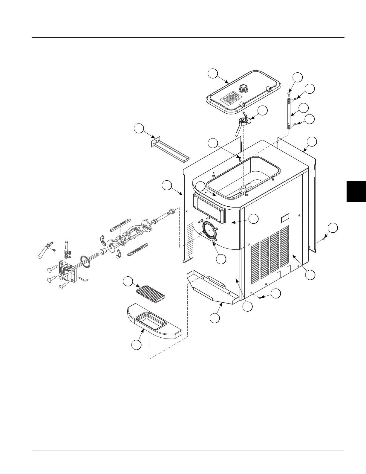
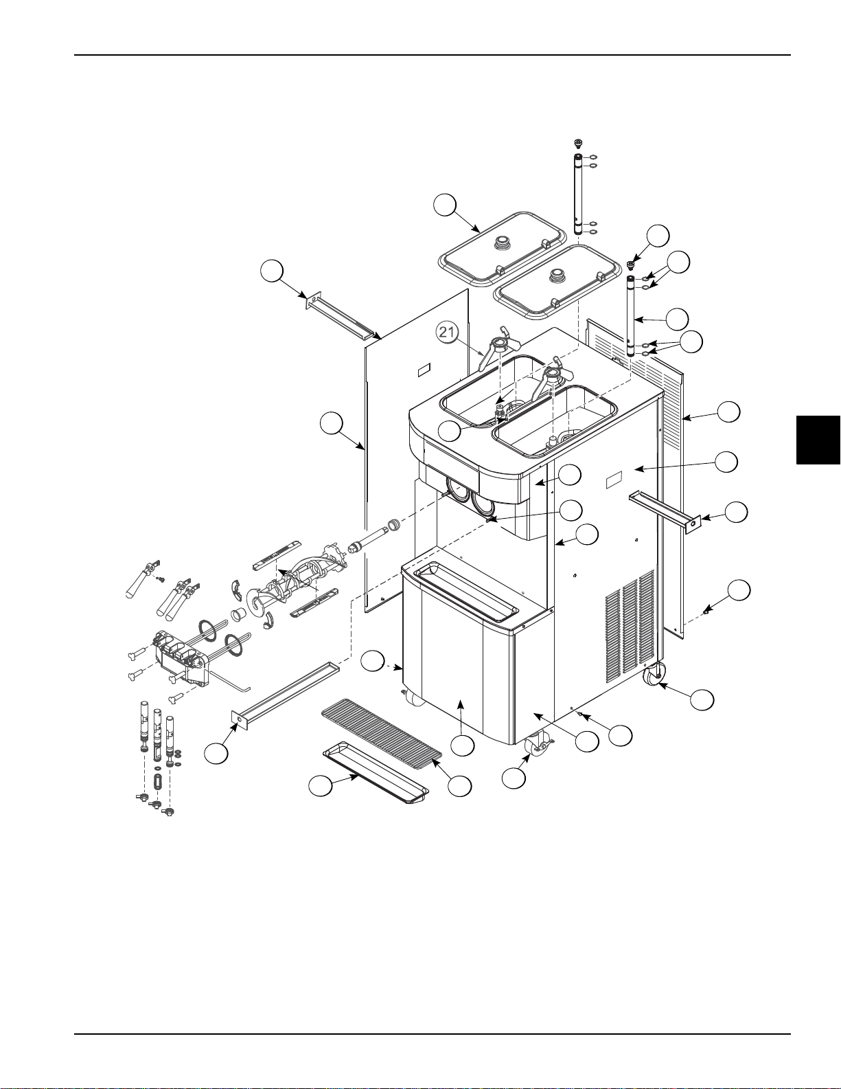
Model C709
Operator Parts Identification
4
Operator Parts Identification
Figure 4-1
Models C709 & C717
4-1
OPERATOR PARTS IDENTIFICATION
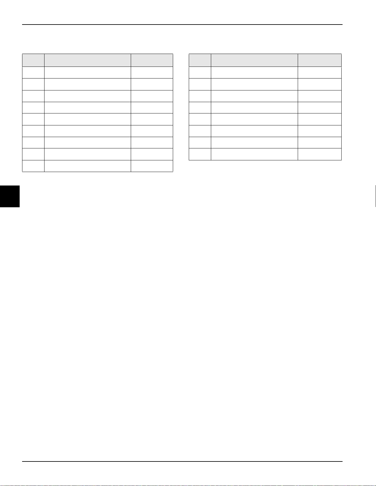
Model C709 Exploded View Parts Identification
Item Description Part No.
1 Panel-Side-Left 056963-SP1
2 Pan-Drip 11-5/8 Long 027503
3 Pin-Retaining-Hopper CVR 043934
4 Kit A.-Cover-Hopper X65368
5 Blade A.-Agitator X56591
6 Orifice 022465-100
7 O-ring-.643 OD x .077W 018572
8 Tube A.-Feed-SS-5/32 Hole X29429-2
9 Panel-Rear 083017-SP1
4
Item Description Part No.
10 Screw-1/4-20x3/8 RHM-SS 011694
1 1 Panel-Side-Right 058932
12 Panel A.-Front-Upper X59423
13 Panel A.-Front-Lower X81480
14 Shelf-Tray-Drip 056076
15 Stud-Nose Cone 055987
16 Tray-Drip 056858
17 Shield-Splash 049203
4-2
Models C709 & C717
Operator Parts Identification
Model C717
5
7
2
20
9
22
3
4
6
7
8
12
8
13
14
16
15
19
17
18
3
1
10
11
OPERATOR PARTS IDENTIFICATION
4
Figure 4-2
Operator Parts Identification
Models C709 & C717
4-3
OPERATOR PARTS IDENTIFICATION
Model C717 Exploded View Parts Identification
Item Description Part No.
1 Kit A.-Cover-Hopper X67061
2 Orifice 022465-100
3 O-ring-.643 OD x .077 Wide 018572
4 Tube A.-Feed-SS-5/32 Hole X29429-2
5 Panel-Rear 059917
6 Panel-Side-Right 062161
7 Pan-Drip 12-1/2 Long 059736
8 Screw-1/4-20 x 3/8 RHM-SS 011694
9 Panel A.-Front(Upper) X59836
10 Stud-Nose Cone 055987
11 Panel A.-Front(Middle) X63879
4
12 Caster-4" SWV 3/4-10 STM 044106
Item Description Part No.
13 Panel-Corner-Frnt-Right 063087
14 Caster-4" SWV 3/4-10 Stem
w/Brake
15 Panel A.-Front Lower X59854-SER
16 Shield-Splash-Wire-19-3/4 033813
17 Tray-Drip-19-5/8 L x 4-7/8 033812
18 Pan-Drip 19-1/2 Long 035034
19 Panel-Corner-Frnt-Left 063088
20 Pin-Retaining-Hopper CVR 043934
21 Blade A.-Agitator X56591
22 Panel-Side-Left 062160
046437
4-4
Models C709 & C717
Operator Parts Identification
OPERATOR PARTS IDENTIFICATION
6
10
3
1
6
7
8
9
5
15
14
4
2
13a
11
12
13
6
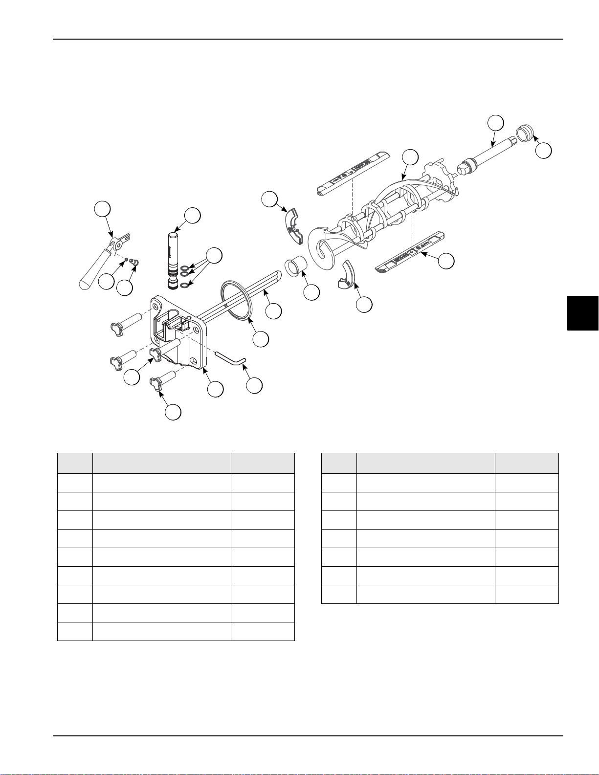
Model C709 Single-Spout Door and Beater Assembly
Item Description Part No.
1 Handle A.-Draw-Push X82875
2 O-ring-1/4 OD x .070W 50 015872
3 Screw-Adjustment-5/16-24 056332-SP
4 Valve A.-Draw X55820
5 O-ring-7/8 OD x .103W 014402
6 Kit A.-Beater-Front Shoes-Bearing X50350
7 Beater A.-3.4QT-1 Pin X46231
8 Shaft-Beater 056078
Figure 4-3
Item Description Part No.
10 Blade-Scraper-Plastic 046235
11 Gasket-Door HT 4"-Double 048926
12 Pin-Handle-SS 055819
13 Door A.-w/Baffle X57332-SER
13a Baffle A.-Long 4 IN w/Rad X50882
14 Nut-Stud-Black 2.563 058764
15 Nut-Stud-Black 3.250 058765
4
9 Seal-Drive Shaft 0325 60
Operator Parts Identification
Models C709 & C717
4-5
OPERATOR PARTS IDENTIFICATION
9
15
2
4
5
8
7
10
5
11
14
13
17
18
3
6
5
12
16
13
14
1
1a
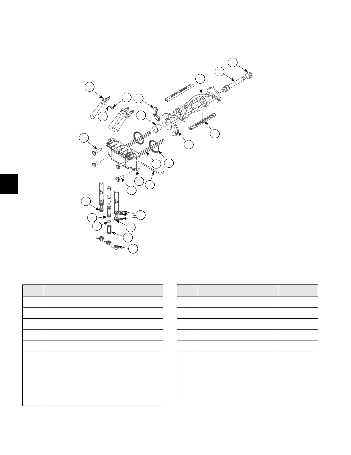
Model C717 Three-Spout Door and Beater Assembly
4
Item Description Part No.
1 Door A.-*LG BAF*W/O PRG* X59923-SER
1a Baffle A.-Long 4 IN W/RAD X50882
2 Handle A.-Draw-Push X82875
3 O-ring-1/4 OD x .070W 50 015872
4 Screw-Adjustment-5/16-24 056332-SP
5 Kit A.-Beater-Front Shoes-Bearing X50350
Figure 4-4
Item Description Part No.
10 Gasket-Door HT 4"-Double 048926
1 1 Pin-Handle-Twin 059894
12 Nut-Stud Black 2.563 Short 058764
13 O-ring-7/8 OD x .103W 014402
14 Valve A.-Draw-Left & RT X59888
15 Seal-Draw Valve 034698
6 Beater A.-3.4QT-1 Pin X46231
7 Shaft-Beater 032564
8 Seal-Drive Shaft 032560
9 Blade-Scraper-Plastic 084350
4-6
16 Valve A.-Draw-Center X59890
17 Nut-Stud Black 3.250 Long 058765
18 Cap-Design 1.010” ID 6 PT 014218
Models C709 & C717
Operator Parts Identification
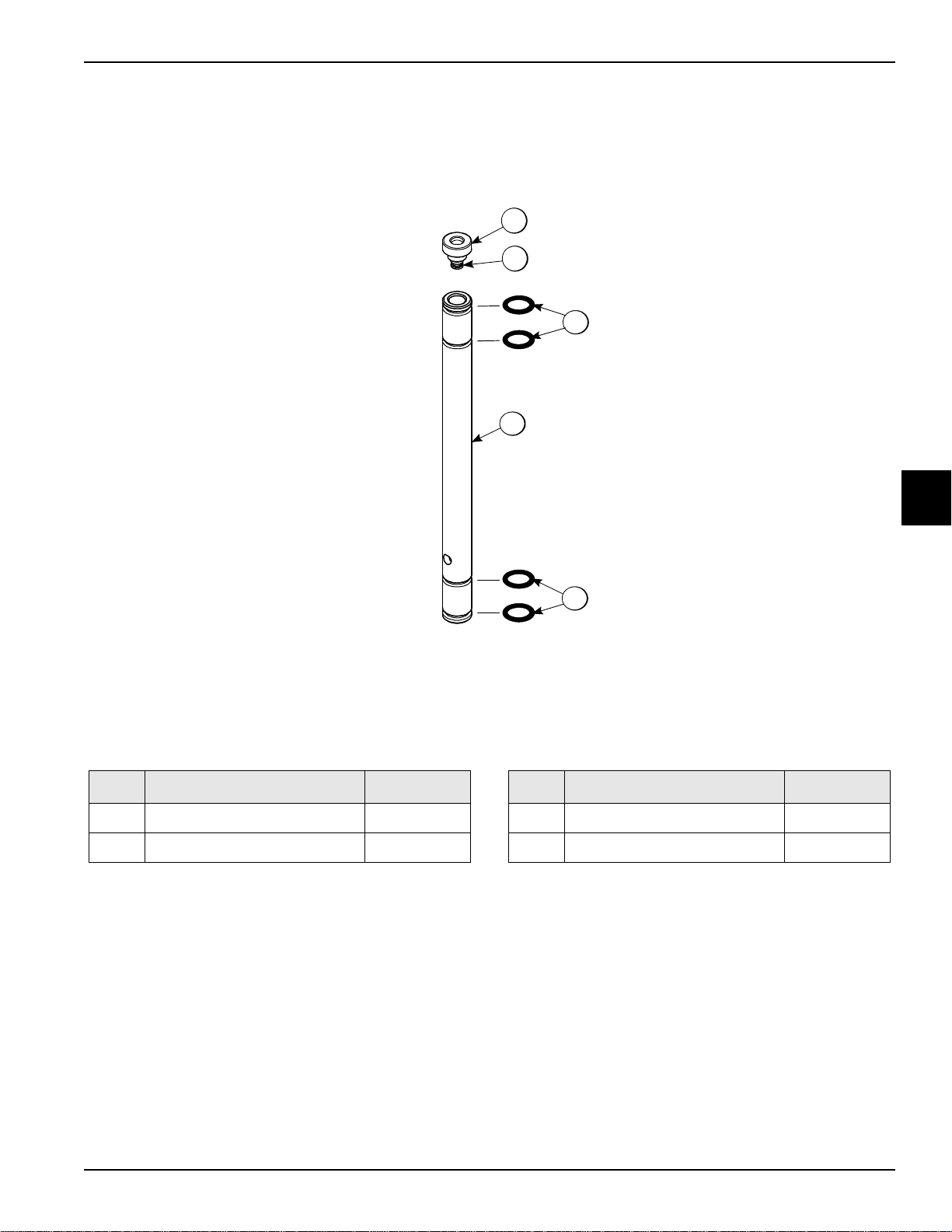
Feed Tube Assembly
3
4
3
1
2
OPERATOR PARTS IDENTIFICATION
Item Description Part No.
1 Orifice 022465-100
2 O-ring-3/8 OD x .070W 016137
Figure 4-5
4
Item Description Part No.
3 O-ring-.643 OD x .077W 018572
4 Tube A.-Feed-SS-5/32 Hole X29429-2
Operator Parts Identification
Models C709 & C717
4-7

OPERATOR PARTS IDENTIFICATION
Apply the appropriate
Taylor approved food safe lubricant.
HP
3
4
1
2
Accessories
4
Item Description Part No.
1 Pail-10 QT. 013163
2 Tool-O-ring Removal Freezer 048260-WHT
3 Lubricant-Taylor HI PERF 048232
*4 Sanitizer-Stera Sheen - Green See Note
Figure 4-6
Item Description Part No.
* * Kit A.-Tune Up-1 Spout (C709) X49463-92B
* * Kit A.-Tune Up-3 Spout (C717) X49463-79B
*Note: A sample container of sanitizer is sent with the
machine. For reorders, order Stera-Sheen
055492 (100 2 oz. packs) or Kay-5
packs).
**Not Shown
®
part no.
®
part no. 041082 (200
4-8
Models C709 & C717
Operator Parts Identification
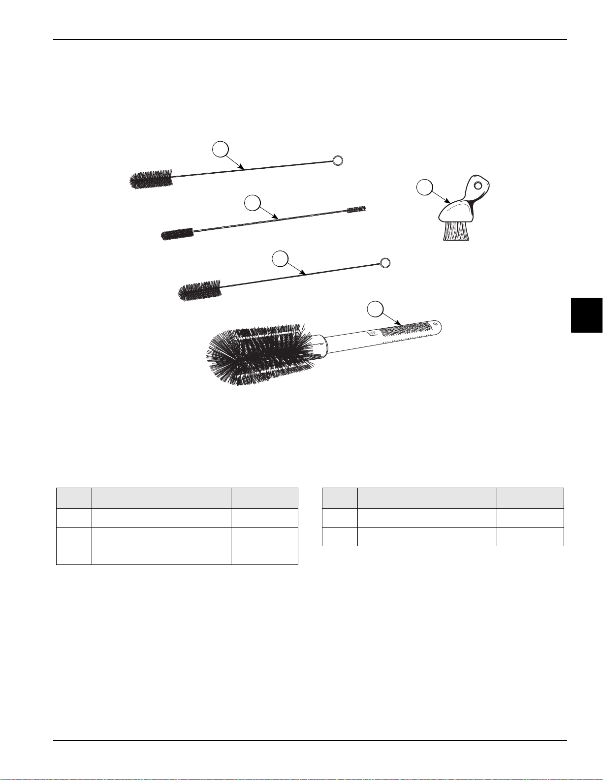
Brushes
1
2
3
4
5
OPERATOR PARTS IDENTIFICATION
Item Description Part No.
1 Brush-Rear BRG 1” D x 2” L 013071
2 Brush-Double Ended 013072
3 Brush-Draw Valve 1”OD x 2 013073
Figure 4-7
Item Description Part No.
4 Brush-Mix Pump Body 3” x 7” 023316
5 Brush-End-Door-Spout-SS 039719
4
Operator Parts Identification
Models C709 & C717
4-9
 Loading...