


Models QS11/23
Modular Grills
Operating Instructions
074606-M
5/24/04

Complete this page for quick reference when service is required:
Taylor Distributor:
Address:
Phone:
Service:
Parts:
Date of Installation:
Information found on the data label:
Model Number:
Serial Number:
Electrical Specs: Voltage Cycle
Phase
Maximum Fuse Size: A
Minimum Wire Ampacity: A
E May, 2004 Taylor
All rights reserved.
074606-M
Taylor Company
The word Taylor and the Crown design
are registered trademarks in the United States
of America and certain other countries.
a division of Carrier Commercial Refrigeration, Inc.
750 N. Blackhawk Blvd.
Rockton, IL 61072

Table of Contents
Section 1 To the Installer 1............................................
Air Clearance 1.........................................................
Electrical Connections 1.................................................
Installation of Cable Kit 2................................................
Ventilation and Clearance 2..............................................
Leveling Procedures 3...................................................
Section 2 To the Operator 6...........................................
Section 3 Safety 7....................................................
Section 4 Operator Parts Identification 9...............................
QS11 9................................................................
QS23 10................................................................
QS11 Accessories 11.....................................................
QS23 Accessories 13.....................................................
Section 5 Important: To the Operator 15.................................
Operating Screen and Controls 16.........................................
Maintenance Menu 18....................................................
Maintenance Menu F lowchart 21...........................................
Section 6 Operating Procedures 22.....................................
Opening Procedures 22...................................................
Cooking Procedures 24...................................................
Table of Contents Models QS11 & QS23

Table of Contents -- Page 2
r
Cleaning Between Product Runs 25........................................
Cleaning the Grease Tray Partition 26......................................
Closing Procedures 27...................................................
Weekly Cleaning Procedures 28...........................................
Section 7 Troubleshooting Guide 29....................................
Section 8 Warranty Explanation 31......................................
Parts 31................................................................
Labor 31................................................................
Section 9 Parts List 32.................................................
Wiring Diagram 38.......................................................
Note: Continuing research results in steady improvements; t h erefore, in fo rmation
in this manual is subject to change without notice.
E May, 2004 Taylo
All rights reserved.
074606-M
Taylor Company
The word Taylor and the Crown design
are registered trademarks in the United States
of America and certain other countries.
Models QS11 & QS23 Table of Contents
a division of Carrier Commercial Refrigeration, Inc.
750 N. Blackhawk Blvd.
Rockton, IL 61072
Section 1 To the Installer
This machine is designed for indoor use only.
DO NOT install the machine in an area where
a water jet could be used to clean or rinse the machine.
Failure to follow this instruction may result in serious
electrical shock.
Air Clearance
Clearances from the grill to other surfaces are required
for adequate air circulation:
Rear: 3 inches (76 mm) minimum.
Sides: 3 inches (76 mm) to combustible
surfaces;
0 inches (0 mm) to non‐combustible
surfaces;
0 inches (0 mm) between grills in
multiple installations.
Failure to comply with these minimum
clearance requirements will hinder grill perfor‐
mance and cause damage to its components.
In all other areas of the world, equipment should be
installed in accordance with the existing local codes.
Please contact your local authorities.
Stationary appliances which are not equipped with a
power cord and a plug or other device to disconnect
the appliance from the power source must have an
all-pole disconnecting device with a contact gap of at
least 3 mm installed in the external installation.
This equipment is provided with a grounding lug
that is to be properly attached to the rear of the frame
by the authorized installer. The installation location is
marked by the equipotential bonding symbol (5021 of
IEC 60417-1) on the removable panel and the frame.
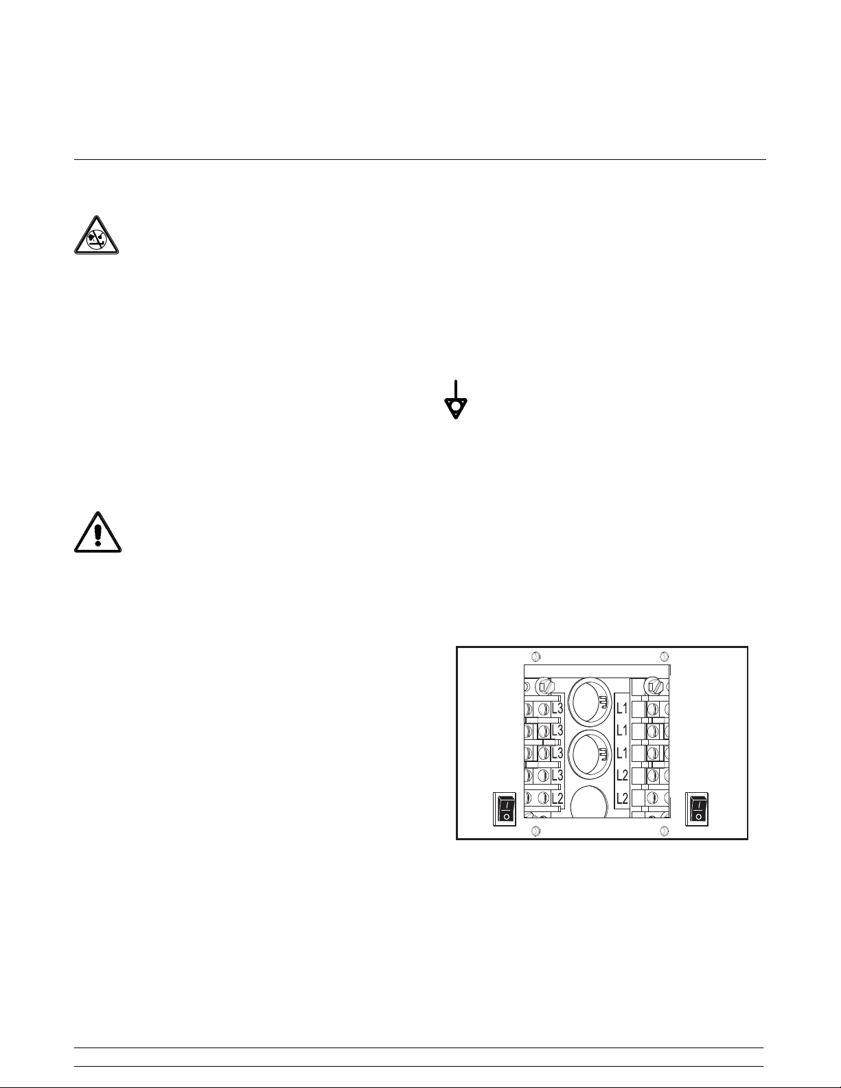
The proper wire size and fused circuit should be
selected according to grill data label information.
Incoming power must be connected to the terminals
with black characters on a white background, as
shown:
Electrical Connections
The QS series grills have one electrical connection.
Check the data plate on the grill for voltage, cycle,
phase and electrical specifications. Refer to the wiring
diagram, provided inside the protective control panel
door at the front of the grill, for proper power
connections. The power connection is located behind
the access line cover on the front of the grill.
In the United States, this equipment is intended to be
installed in accordance with the National Electrical
Code (NEC), ANSI/NFPA 70-1987. The purpose of
the NEC code is the practical safeguarding of persons
and property from hazards arising from the use of
electricity. This code contains provisions considered
necessary for safety. Compliance therewith and
proper maintenance will result in an installation
essentially free from hazard!
14092
Figure 1
071102
Models QS11 & QS23 To the Installer
1

Installation of Cable Kit
Ventilation and Clearance
Kit A.-3 Ft. Restrain Cable (part no. 074948) must be
installed to limit the movement of the grill. This is
necessary in order to protect the electrical conduit
from stress. The cable is made of flexible conduit.
To install the kit, look at the back of the unit. There is
a 1/2” hole on the left side of the frame, about half way
down. Remove the plug and attach the cable.
To ensure proper operation of this appliance it must be
installed so that products of combustion are efficiently
removed. Do not store anything on top of the grill.
Most service can be performed from the front of the
grill. When inspecting heating elements, the unit must
be disconnected and pulled out of the hood enclosure.
Allow four feet in front of the appliance for this purpose.
060504
To the Installer
2
Models QS11 & QS23

Leveling Procedures
Step 1
The leveling adjustment needs to be performed when
the grill is properly gapped and at operating
temperature. Level the grill without the release
material sheets in place.
Step 2
To allow adjustment of the gap pins, loosen the two
1/8” allen screws located on the sides of the front and
rear gap slides.
14110
Figure 2
Step 3
Raise both gap pins on the front gap slide until the
bottom of the screwdriver slot is flush with the top edge
of the gap slide. Repeat this step for the rear gap slide.
Slide the gap slide to the right.
14111
FLUSH
WITH
TOP
Figure 3
Models QS11 & QS23 To the Installer
3
Figure 4
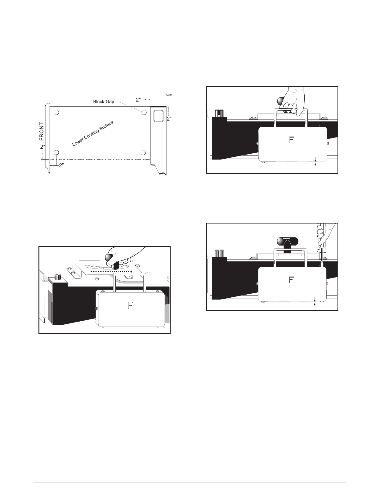
Step 4
For each cook surface requiring adjustment, place the
four gap blocks on the cook surface, approximately 2”
(51 mm) in from each corner. (Figure 5)
Step 6
Wearing proper protection, carefully attempt to raise
the gap slide to evaluate which gap pin is in need of
adjustment.
14113
GAP
Figure 5
Step 5
Lower the cook surface assembly. Loosen and slowly
move the T‐handle to the left until the gap
indicator/pointer is at #8 on the gap indicator plate, and
tighten the T‐handle.
14112
SLIDE
Figure 6
Figure 7
With the gap slide raised, slowly turn the gap pin
needing adjustment until it makes contact with the
cook surface. Note: Do not use force to adjust the pins.
Repeat these steps for both gap slides.
14114
GAP
Figure 8
Step 7
Raise the upper cook surface and remove the four gap
blocks.
To the Installer
4
Models QS11 & QS23
Step 8
Lower the upper cook surface into the COOK position.
14115
Figure 9
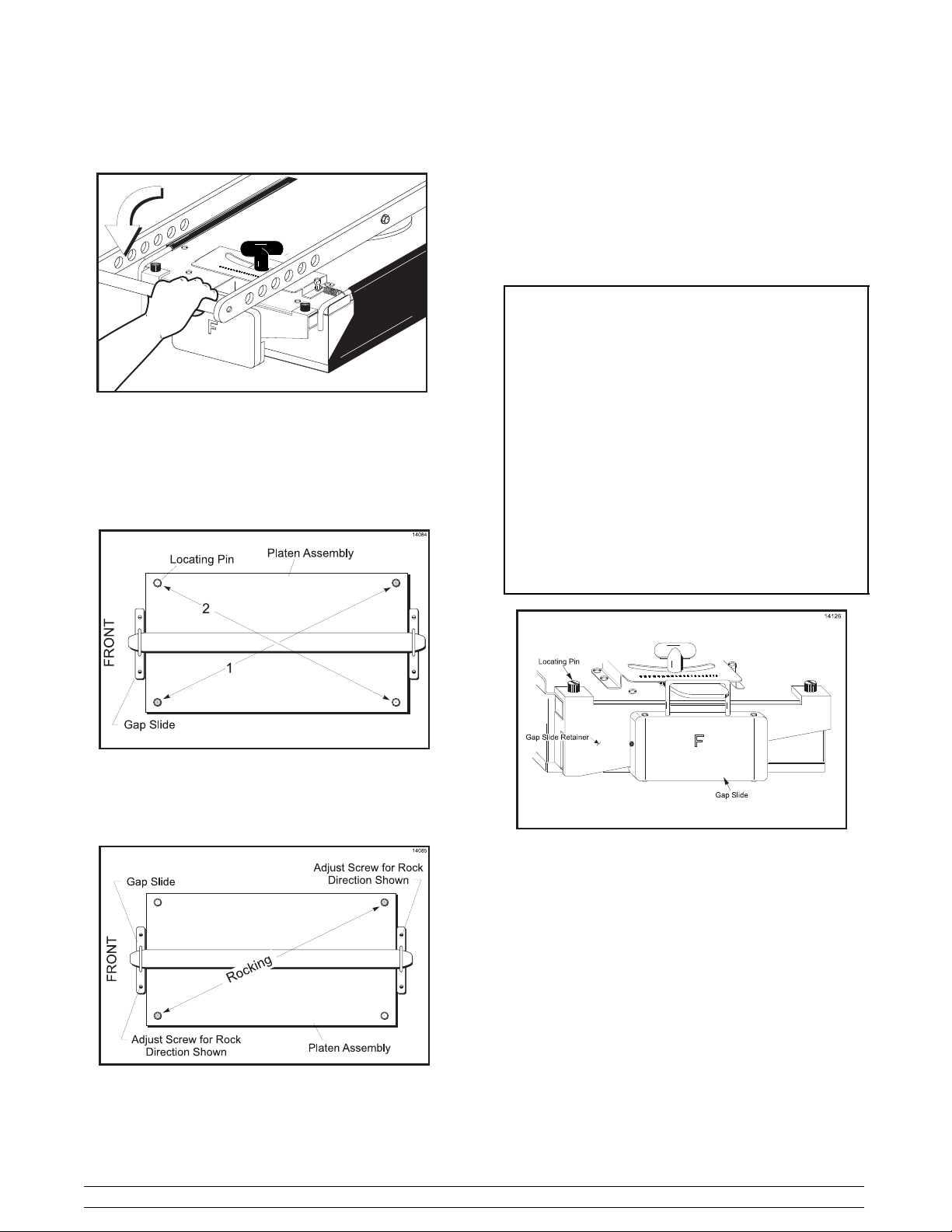
Step 9
Wearing proper protection, attempt to rock the cook
surface assembly. Apply slight pressure on the
locating pins at opposite corners to each other as
shown in Figure 10.
Step 11
After adjusting, verify the unit for stability/rock.
Step 12
If all adjustments on the cook surface are correct, and
no rocking occurs, tighten the two allen screws located
on the sides of the front and rear gap slides to lock all
adjustments from moving.
IMPORTANT: It is highly recommended
that the gap slides and the gap slide
retainers (as shown in Figure 12) be
removed at least weekly for cleaning these
parts and the cook surface shroud behind
these parts.
These parts are easily removed by removing
the locating pins and holding both parts,
because they are not attached together, and
pulling them from the cook surface.
Take the gap slides and the gap slide retainers
to the sink for cleaning. (Be sure to re-install
the gap slides as they were removed, i.e., “F”
front.) See Weekly Cleaning Procedures
on page 28.
Figure 10
Step 10
If the unit rocks, split the adjustment for gap pins
across the uneven corners, as shown in Figure 11.
Figure 12
Figure 11
090401
Models QS11 & QS23 To the Installer
5

Section 2 To the Operator
The grill you have purchased has been carefully
engineered and manufactured to provide dependable
operation. The QS series grills are designed to deliver
“cook‐to‐order” menu items. The two‐sided cooking
method increases speed of service and assures safe
product integrity.
These grills, when properly operated and maintained,
will produce a consistent quality product. Like all
mechanical products, they require cleaning and
maintenance. A minimum amount of care and
attention is necessary if the operating procedures in
this manual are followed closely.
This Operator's Manual should be read before
operating or performing any maintenance on your
equipment.
It is strongly recommended that all personnel
responsible for the equipment's operation and
cleaning, review these procedures for proper training
and assurance that no misunderstandings exist.
In the event that you require technical assistance,
please contact your local authorized Taylor Distributor.
affixed to this product, it signifies that this product is
compliant with the EU Directive as well as other similar
legislation in effect after August 13, 2005. Therefore,
it must be collected separately after its use is
completed, and cannot be disposed as unsorted
municipal waste.
The user is responsible for returning the product to the
appropriate collection facility, as specified by your local
code.
For additional information regarding applicable local
laws, please contact the municipal facility and/or local
distributor.
If the crossed out wheeled bin symbol is
050831
To the Operator
6
Models QS11 & QS23
Section 3 Safety
We at Taylor Company are deeply concerned about
the safety of the operator when he or she comes in
contact with the grill and its parts. Taylor has gone to
extreme efforts to design and manufacture built‐in
safety features to protect both you and the service
technician. As an example, warning labels have been
attached to the grill to further point out safety
precautions to the operator.
To Operate Safely:
3” (76 mm) from all combustible materials
(0” to non-combustible materials).
Failure to comply could result in a fire hazard.
All grills require 3” (76 mm) of air clearance in the rear.
Failure to comply will hinder grill performance.
Grill clearance must be maintained at least
DO NOT operate the grill without reading this
operator's manual. This manual should be kept in a
safe place for future reference.
This equipment is provided with a grounding lug
that is to be properly attached to the rear of the frame
by the authorized installer. The installation location is
marked by the equipotential bonding symbol (5021 of
IEC 60417-1) on the removable panel and the frame.
S DO NOT operate the grill unless it is
properly grounded.
S DO NOT use the cord if it is frayed.
S DO NOT attempt any repairs unless the
power supply to the grill has been
disconnected.
S DO NOT operate the grill unless all service
panels are restrained with screws.
S Stationary appliances which are not
equipped with a power cord and a plug or
other device to disconnect the appliance
from the power source must have an
all-pole disconnecting device with a contact
gap of at least 3 mm installed in the external
installation.
Failure to follow these instructions may result in
electrocution. Contact your local Taylor Distributor for
authorized service.
DO NOT use a water jet to clean or rinse the
grill. Failure to follow this instruction may result in the
following:
S serious electrical shock
S burns from hot steam
S liquid collecting inside the grill and
destroying electrical components.
S DO NOT prepare or remove product without
proper equipment.
S DO NOT allow untrained personnel to
operate this grill.
S USE EXTREME CAUTION when cleaning
the grill.
Failure to follow these instructions may result in severe
burns from high temperatures.
040408
Models QS11 & QS23 Safety
7
This grill must be placed on a level surface.
Failure to comply may result in personal injury or
equipment damage.
CAUTION: DO NOT attempt to use the grill
during a power outage. Grills require electrical
power for operation. In the event of a prolonged power
outage, place the unit in the “OFF” position.
DO NOT slide the grill with the legs attached.
Failure to follow this instruction may damage the grill.
NOISE LEVEL: Airborne noise emission does not
exceed 70 dB(A) when measured at a distance of 1.0
meter from the surface of the machine and at a height
of 1.6 meters from the floor.
040210
Safety
8
Models QS11 & QS23
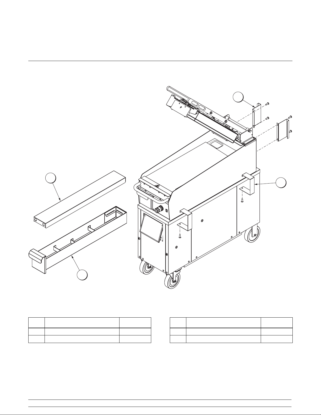
Section 4 Operator Parts Identification
QS11
3
1
2
ITEM DESCRIPTION PART NO.
4
Figure 13
ITEM DESCRIPTION PART NO.
1 COVER-TOP 079969
2 TRAY A.-GREASE X79940-SER
Models QS11 & QS23 Operator Parts Identification
9
3 STANDOFF-REAR 079288
4 STANDOFF-FRONT 079289
071102
 Loading...