

MANUAL OF USE AND
MANUEL D’UTILISATION
MANUAL DE USO Y
MANUALE D’USO E
ELECTRONIC PASTEURIZERS WITH BAIN-MARIE
PASTEURISATEURS ELECTRONIQUES BAIN-MARIE
PASTORIZADORES ELÉCTRONICOS CON BAŇO MARIA
PASTORIZZATORI ELETTRONICI A BAGNOMARIA
MAINTENANCE
ET D’ENTRETIEN
MANUTENCION
MANUTENZIONE
Series-Série-Serie
CH03 05
CH04 04
CH05 04

1 - ENGLISH
We recommend to carefully and fully read the present manual before using your
TAYLOR machine.
In your own interest, pay particular attention to the following warnings:
IMPORTANT
The non-observance of this warning can jeopardize the user’s health and the
correct operation of the machine.
The machine is covered by guarantee according to the conditions reported in the Seller’s
In the following field, please write your machine serial number in capital letters
Serial number
Distributor’s stamp
ENGLISH - 2

Congratulations on purchasing a machine TAYLOR.
The present manual, enclosed to the machine, is integrant and essential part of the
machine and shall be delivered to the final user. Before performing any kind of operation, it
is recommended to carefully study the reported instructions, as only a careful reading
allows you getting the highest performance from your machine. The following pages report
all information necessary to correctly install, commission, adjust and service your machine.
TAYLOR reserves the right to carry out all changes necessary to improve its product or
manual without prior notice and to insert them in the subsequent issues.
INDEX
1. TRANPORT, HANDLING AND STORAGE .…………………….…………. 4
2. MARKINGS AND GRAPHICS ………………………………………… 5
3. INSTALLATION ………………………………………… 7
3.1 Field of use ………………………………………… 7
3.2 Limits of use ………………………………………… 7
3.3 Machine outfit ………………………………………… 7
3.4 Commissioning ………………………………………… 7
4. SAFETY DEVICES ………………………………………… 10
5. OPERATION ………………………………………… 11
5.2.1CH03 – CH04 operation ………………………………… 15
5.2.2 CH05 operation ………………………………… 17
6. MAINTENANCE ………………………………………... 18
6.1 Routine maintenance ………………………………………… 18
6.1.1 Cleaning and sanitization ………………………………… 18
6.2 Extraordinary maintenance ………………………………………… 20
6.2.1 Refrigeration plant ………………………………………… 20
6.2.2 Electric system ………………………………………… 20
7. TROUBLE-SHOOTING …………………….………………… 21
7.1 Alarm management ………………………………………… 21
7.2 Trouble-shooting ………………………………………… 22
8. APPENDICES ………………………………………… A1
1.1 Preliminary inspection ………………………………………… 4
1.2 Machine unpacking ………………………………………… 4
1.3 Packing dimensions ………………………………………… 4
5.1 Control panel ………………………………………… 11
5.2 Use of programs ………………………………………… 15
8.1 Technical data ………………………………………… A1
3 - ENGLISH

1 TRANSPORT, HANDLING AND STORAGE.
1.1 PRELIMINARY INSPECTION
The machine travels at the customer’s risk. In case packing is damaged, immediately
inform the carrier.
Immediately inform the carrier also in case of damage to the machine, even if you open
the packing a few days after the delivery.
It is always advisable to accept the goods SUBJECT TO INSPECTION.
The equipment shall be assembled with great care: falls and shocks can damage it without
showing external damages.
1.2 MACHINE UNPACKING
For a correct machine unpacking, carefully follow the instructions hereunder reported:
in case of packing carton on wooden frame:
• Remove the strap fixing the carton to the bottom and take the packing off from the top.
In case of wood case:
• Remove the case upper side and the side walls by means of a nail drawer, pay
attention not to disperse the nails and the wood splinters;
• Remove the plastic bag and put it in a safe place;
• Unscrew the machine side panels by means of a cross and/or cut screw-driver;
• Turn out the screws fixing the packing lower side to the machine by means of a 17mm
wrench;
• Remove the packing lower part, lift the machine and hook it up to the lifting points
specified on the frame with the symbols;
• Reposition the side panels.
The packing shall be stored in a dry place, out of the children’s reach. It can be used
again, if correctly preserved, for a possible transfer of the machine.
The storing temperature shall range between -13°F and +131 °F.
Humidity shall range between 30 and 95%.
Packing elements such as plastic bags, nails, expanded polystyrene, cartons, etc. must be
left out of the children’s reach.
1.3 Packing dimensions
MODEL
CH03
CH04
CH05
SIZES (CM) WEIGHT N- L (KG)
50X90X130 159-190
50X113X130 200-248
90X113X130 335-410
CASE
ENGLISH - 4
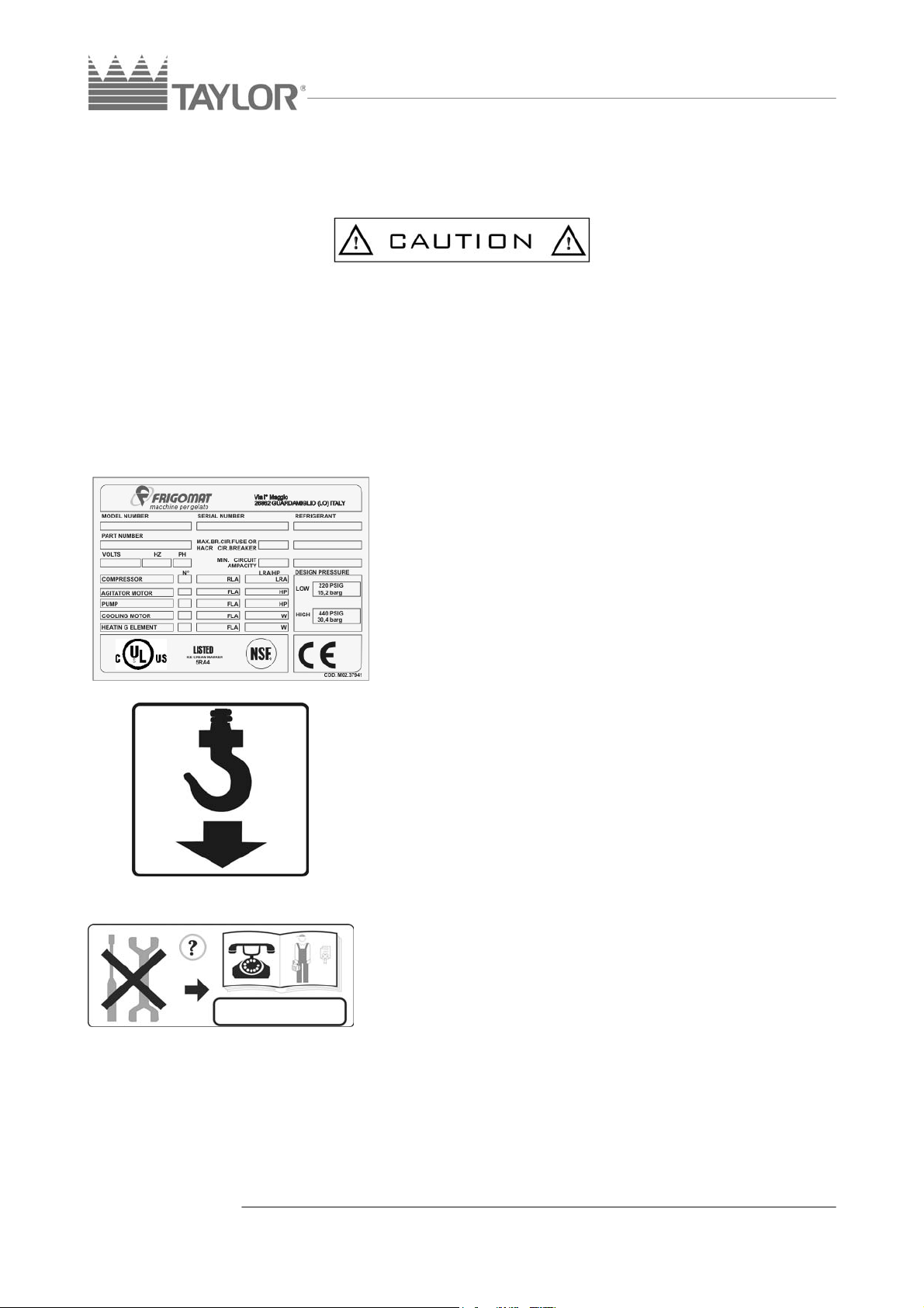
2. MARKINGS AND GRAPHICS
Never touch the machine with hands and tools during production or maintenance and
cleaning operations, without making sure that the machine is in STOP position, the master
switch is off and/or the multipolar plug disconnected.
TAYLOR declines any liability for accidents deriving from an improper use of the machine
due to the non-compliance with the above-mentioned recommendations.
The machine is provided with a plate and some pictograms, which together with the
present manual allow using the machine in safer conditions.
Machine data plate
The adhesive label located on the back of the
machine allows identifying the model and reports the
following indications:
Manufacturer’s name and address; Machine model
and version; Serial number; Rated electrical
characteristics; Type and weight of employed Freon;
Manufacturing year.
Indication
Points of application of lifting devices.
The following plate is placed on the four sides of the
frame lower part and shows the points where lifting
hooks shall be positioned in order to perform this
operation in safe conditions. By means of a cross
screw-driver unscrew the two side panels and then
position the lifting devices into the apposite points.
Make sure that they cannot accidentally come out
during lifting operations.
Warning!
Maintenance allowed to qualified personnel only.
The following plate placed on the machine back panel
forbids extraordinary maintenance operations and/or
repairs delegating them to authorized people only,
whose address is indicated in the provided space.
5 - ENGLISH

Warning!
Do not touch with hands.
The following plate placed on the back of air-cooled
machines shows that cleaning operations on the heat
exchanger shall be carried out only by means of a
brush or an exhauster.
Warning!
High voltage inside, danger of fulguration.
The following plate is placed on the electric box cover
and warns the operator that in no case the cover must
be removed avoiding this way the risk of lethal
fulguration. Also in this case, maintenance operations
on internal components must be performed by
authorized personnel only.
Warning!
Risk of crashing.
The following plate is applied on the upper panel on
the tank cover right side and shows that it is
necessary to pay attention to the cover both during
cleaning and loading operations. In fact it can fall
down if accidentally knocked causing injuries to the
operator.
All CH pasteurizers are equipped with an advanced
shearing-prevention system able to stop moving
elements when the cover is opened. Nevertheless, all
cleaning and maintenance operations shall be carried
out when the machine is in “STOP” position and the
master switch turned off.
ENGLISH - 6

3. INSTALLATION
3.1 FIELD OF USE
Equipment suitable to the preservation and low and high pasteurization of food mixture for
ice-cream for appropriate legal purposes.
3.2 LIMITS OF USE
Never use the machine with variable supply voltage and/or more than +/- 10% of the value
showed in the nameplate or when the feeder is damaged;
Do not use the machine for purposes different from the ones indicated in the present
manual;
Do not use the machine in explosive environment;
Do not wash the machine with high-pressure jets of water or poisonous substances;
Do not expose the machine to excessive heat or humidity;
Do not use completely unbalanced mixtures and/or quantities not in compliance with the
specifications reported on the packing.
3.3 MACHINE OUTFIT
- Disk wheel
- Cleaning rod
- Gasket dismantling tool
- Stiff paddle
- Packing screw
- Packing washer
- Flat packing washer
- Cock O-Ring 3112
- Cock O-ring 3075
3.4 COMMISSIONING
Bring the machine to the place of employment and check that everything is all right as far
as installation concerns:
A. Power supply;
B. Water supply (only in case of water condensing);
C. Suitable run-off pit for water (only in case of water condensing).
• Lock the machine by means of the apposite lever located on the front wheels;
• Place the machine far from walls or other obstacles (at least 10 cm sideways and 30 on
the back). In case the machine is provided with water-cooled condenser, the distance
between the wall and the back panel can be reduced to 10 cm.
• Make sure that the supply voltage and power comply with the values reported on the
rating plate placed on the back panel;
• Connect the machine to the mains; upstream the machine, arrange an omnipolar
master switch with minimum contact opening equal to 3 mm and adequate power,
interlocked with fuses to allow plugging and unplugging at open circuit.
- Cock O-ring 121
- Cock O-ring 4087
- Pivot O-ring 2018
- Lubricant
- Squeese bottle
- Use and maintenance manual
- Declaration of conformity
- Certificate of guarantee
7 - ENGLISH

• Connect the feeder to a type-approved plug: the feeder shall be well stretched, to avoid
rolling and overlapping. It shall not be exposed to possible shocks or tampering
attempts and far from liquids, water and heat sources. It shall not be damaged,
otherwise make it be replaced by qualified personnel with another section and type
5G4 H07RN-F (for version 400 V), before connecting the machine to the mains.
• Arrange the connection of the yellow-green wire to a good earth connection.
• Put the machine metallic parts to earth by means
of the apposite equipotent fastening screw located
on the back under the frame and marked by the
symbol showed on the left.
• Make sure that the water supply system is
provided with sufficient pressure for a correct
operation of the condensing plant. A residual
pressure ranging between 1 bar and 3 bar is
considered suitable.
• Connect the condensing water inlet hose to the
inlet showed in the picture by means of a rubber
hose Ø1/2”. Interpose a cut-off cock at the
operator’s reach.
• Connect the condensing water outlet hose to the
outlet showed in the picture by means of a hose
connector Ø1/2” and bring it to the discharge.
• Both for inlet and outlet connections it is advisable
to make use of linenized hoses suitable to
withstand pressures up to 10 bar and apposite
hose clamps DIN 3017.
• The water outlet hose shall have a min. inclination
of 3 cm for each meter of length.
• In case of water condensing it is necessary to
check that the water valve correctly works.
• After both inlet and outlet hoses have been
connected, open the cut-off cock and make sure
that the discharge does not leak liquid when the
machine is not working. If this is the case, apply to
a qualified customer service.
• After the master switch has been turned on, press
pushbutton 5 to start up the compressor motor.
After a few seconds the condensing water shall
regularly come out of the outlet hose end at a
temperature of 35°C. Press pushbutton 10 STOP
to stop the machine. In case of troubles, apply to
the customer service.
• For the three-phase version only, check that the
mixer sense of rotation is clockwise:
• Close the tank cover and start up mixing by means
of pushbutton 9. Check that the disk wheel inside
ENGLISH - 8

the tank clockwise rotates as showed in the
picture.
• Press pushbutton 10 STOP to stop the machine.
• In case the sense of rotation is not clockwise,
remove voltage and exchange the two wires of the
feeder between themselves.
• The ideal temperature shall range between
15°(59°F) and 35°C (95°F);
• The ideal humidity shall range between 30 and
60%.
TAYLOR declines any liability for damages to persons and/or things due to a wrong
installation and/or the non-compliance with the industrial accident prevention standards.
Never touch the machine with hands, both when it is on duty and during cleaning and
maintenance operations, without making sure that the machine has been stopped by
means of pushbutton 10 STOP and the master switch has been turned off. Never clean
the machine by means of high pressure jets of water. Never close the cut-off cock while
the machine is running. Pay attention not to damage the feeder. In case of necessity,
make it be replaced.
In case the machine provided with water-cooling is left at a room temperature inferior to
0°C (32°F), it is necessary to run off all water present inside the condenser before starting
up the machine.
9 - ENGLISH

4. SAFETY DEVICES
Shearing prevention system: realized by means of a NO micro-switch in conformity with
the European standard. It stops the mixer motor when the tank cover is opened;
Motor reliability of service: realized by means of overload relays, which can be manually
reset. They protect the machine motors against overloads and the pushbuttons STOP and
TER contemporarily light up. An acoustic signal (beep) is issued every 10 seconds. To
reach the overload relay, press the reset pushbutton once or twice at the most to avoid
burning the motor winding.
Auxiliary circuit supply safety system (24 V): realized by means of an insulating
transformer according to the European Standards in force. In case of trouble it prevents
the primary circuit voltage from being present on the auxiliary elements (probes, logic unit,
solenoid valves, etc.).
Protection against auxiliary equipment short-circuit: realized by means of modular
magneto-thermal circuit-breakers, that trip in case of short-circuit on the logic unit or on the
auxiliary power supply.
The cut-off function is automatically restored after removing the problem making the safety
system trip.
Glycol circuit alarm: when the machine is in STOP position and the FLU led is lighted up,
the glycol circuit is in trouble (opened water valve and blocked pump).
Fluid level alarm: when the FLU led blinks the level of fluid has reached the bottom and it
is necessary to check the circuit.
Safety thermostat alarm: when the machine is in STOP position and the TER led is
lighted up, the fluid safety thermostat or one of the motor protection has tripped.
Temperature probe alarm: when the machine is in STOP position and the TEM led is
lighted up, the temperature probe circuit does not correctly work.
In any case the machine carries out a series of tests during production:
Logic unit self-reset in case of lack of power supply
• Diagnosis of control panel flashing signal lights: all leds present on the panel light up for
10 seconds at each current reset and show the operator their functions. Press any key
to exit this function.
• Automatic reset of the previously set-up function.
Logic unit self-diagnosis (watch-dog)
• Microprocessor diagnosis and maintenance of program data: it controls possible
internal troubles and stops the card in case of failure.
ENGLISH - 10

5. OPERATION
5.1 CONTROL PANEL
Digital display
Switching on the machine, the display shows an abbreviation
composed of a letter followed by two figures: for example the
abbreviation P1.3 shows the program type P = PASTEURIZER and
1.3 NUMBER OF SOFTWARE VERSION.
Possible indications:
¾ 32-210: temperature in °F of the mixture inside the tank;
¾ 86-194°F: set-up value of temperature in SEMI-AUTOMATIC
0-120 minutes: set-up value of pause time in SEMI-AUTOMATIC
mode (pasteurizer only).
1. Digital display
2. Water-cock pushbutton
3. STOP/VALUE CONFIRMATION
pushbutton
4. Pushbutton for the introduction of water
into the tank / VALUE CANCELLATION
5. Fluid alarm
6. Overload relays alarms
7. Temperature alarm
8. “SEMIAUTOMATIC” pushbutton
9. “HIGH PASTEURIZATION” pushbutton
10. “LOW PASTEURIZATION” pushbutton
11. “COOLING” and “PRESERVATION”
pushbutton
12. “LOW MIXING” pushbutton
cycle (pasteurizer only);
11 - ENGLISH

Water-cock pushbutton
This pushbutton carries out two functions:
1. press it to introduce water into the cock and wash it. The delivery
of water keeps on as long as the pushbutton is pressed.
2. if the pushbutton is lighted up this means that programming of
heating temperature or preservation time is active. Press it to
decrease the value showed by the display. Once the desired
value has been selected, press STOP pushbutton to confirm and
save it.
The water-cock function is active with any other function in progress,
STOP included.
STOP/VALUE CONFIRMATION pushbutton
This pushbutton carries out 3 functions:
1. press the pushbutton to cancel the function in progress and stop
the machine;
2. if the SEMI-AUTOMATIC pushbutton has been pressed and the
cock-washing led and the water-tank led are lighted up, press this
pushbutton to confirm both storage of the program and the
parameter showed on the display, the mixture heating
temperature in °F or this temperature preservation time expressed
in minutes for pasteurizers;
3. It restores the machine functions after the machine has been
stopped due to an alarm signal.
Pushbutton WATER – TANK/ VALUE CANCELLATION
This pushbutton carries out 2 functions:
1. Press it and the flexible shower delivers water for a preset time of
2’ and 30”. To stop delivery press the pushbutton again;
2. if the pushbutton is lighted up, press it to increase the numerical
value showed by the display (heating temperature and
preservation time). Once the desired value has been selected,
press stop to confirm and save it. The function water-tank is active
with any other function in progress, STOP included.
“SEMIAUTOMATIC” pushbutton
This pushbutton gives the operator the possibility to select the
desired cycle and to have the correct pause time indication for a
perfect pasteurization. In case it is necessary to change this time,
due to special requirements, the operator can do it by directly
programming on the pushbutton panel, with machine in STOP
position.
ENGLISH - 12

By pressing the SEMI-AUTOMATIC pushbutton the water-cock and water-tank
pushbuttons light up and the STOP pushbutton remains lighted up to show that the
pushbutton panel is ready for programming.
The digital display shows the heating temperature value programmed for the last SEMIAUTOMATIC cycle.
If this value is suitable to the kind of mixture, which is going to be processed, it is sufficient
to press the STOP pushbutton to confirm the value and save it. The display will
automatically show the time required for a correct pasteurization.
On the contrary, if it is necessary to program a different value, press the water-cock
pushbutton to decrease the value or water-tank pushbutton to increase it.
Once the desired value has been set up, press the STOP pushbutton to confirm and save
it. The SEMI-AUTOMATIC pushbutton starts up blinking to show that the pushbutton panel
is ready to program the heating temperature preservation time.
If this value is suitable to the mixture requirements, press the STOP pushbutton to start up
the selected pasteurization cycle, which is automatic. To each cooking temperature
corresponds a defined preservation time. All preservation times necessary to carry out a
correct pasteurization from 60°C(140°F) to 85°C (185°F), arranged degree by degree, are
stored in the machines CH series.
We recommend the operators not to modify these times, which moreover automatically
appear on the display without being necessary to remember it.
However, in case the operator intends to process some ingredients at his will, it is possible
to change both temperature and aging time, it will be sufficient to press the water-cock and
the water-tank pushbuttons to decrease or increase the values.
Once the desired combination has been fixed, press the STOP pushbutton again to
confirm it and start up the desired mixing and/or heating cycle. Remember that
pasteurization is carried out in memorized programs only.
In LOW and HIGH PASTEURIZATION or SEMI-AUTOMATIC mode, the tank cover
opening makes the mixer motor, the heating resistor and the refrigeration compressor
immediately stop, but not the glycol circulation pump
During all these phases it is possible to wash the cock and introduce water into the tank,
always with the display showing the mixture temperature.
“HIGH PASTEURIZATION” pushbutton
185°F
Press this pushbutton to start up heating with switched-on mixer
motor, glycol pump and heating resistor until the temperature reaches
the value of 85°C (185°F).
Once the preset value of 85°C (185°F) has been reached, the cooling
cycle begins until the mixture preservation temperature of 4°C (39°F) is reached. At the
end of the cooling cycle the preservation cycle begins.
.
13 - ENGLISH

149°F
39°F
“LOW PASTEURIZATION” pushbutton
Press this pushbutton to start up the mixer motor, the heating resistor
and the glycol pump until the temperature of 65°C (149°F) is reached
and showed on the display.
Once the temperature of 65°C (149°F) is reached the preservation
cycle of 30 minutes begins, at the end of which the cooling cycle
begins until the preservation temperature of 4°C (39°F) is reached.
At the end of the cooling phase, the preservation cycle begins.
COOLING/PRESERVATION pushbutton
Press this pushbutton to start up cooling the mixture with working
mixer motor, refrigeration compressor and glycol circulation pump,
until the mixture inside the tank reaches a temperature of 4°C (39°F),
stopping all machine functions.
Subsequently, the compressor (if necessary) and the mixer will
automatically start up running for 15” every 4 minutes.
During the entire cycle, the display shows the temperature value of
the mixture inside the tank.
“LOW MIXING” pushbutton
When the machine is in STOP position, press the MIXING
pushbutton to start up the mixer and allows mixing. If the tank cover
is open, the mixer motor does not start up until the cover is
closed.
The display shows the temperature of the product inside the tank.
Before introducing the mixture or the ingredients, it is advisable to
accurately wash and sanitize the machine. It is also advisable to
check that the piston gaskets are correctly placed and close it.
ENGLISH - 14

5.2 HOW TO USE THE PROGRAMS
“Beep” switching off
In case the buzzer is enabled, a short pressure of the pushbutton corresponding to the
cycle in progress, allows switching the buzzer off until it is enabled again.
“SKIP” function
During the pause times set up in cycles, normally indicated by the display blinking, to reset
the time of current “STEP”, keep the pushbutton corresponding to the cycle in progress
pressed for at least 5 seconds.
TIME SET display
Press the pushbutton corresponding to the cycle in progress to display the time set of the
“STEP” in progress.
The pushbutton shall be released after 5” otherwise the “SKIP” function of pause time
reset automatically intervenes.
Energy-saving mode
A minute after one of the pushbutton has been pressed, the display brightness is reduced
to lower the electronic card. The correct brightness degree is restored as soon as a
pushbutton is pressed.
5.2.1 CH03-CH04 OPERATION
Before preparing the mixture, it is advisable to accurately wash and sanitize the machine.
Pour some liquid (milk or water) into the tank covering the mixer disk wheel for at least 10
cm.
Press the MIXING pushbutton.
Add the solid components such as sugar, eggs, flavours and powdered ingredients and
avoid introducing solid fats which shall be add warm.
Add the remaining liquid raw materials to complete the recipe, then press STOP.
Select the desired working cycle among the available ones:
HIGH PASTEURIZATION AT 85°C (185°F)
It is suitable for mixtures with ingredients (fats, chocolate, etc.) requiring high temperatures
for a complete melting.
Pour some liquid (milk or water) into the tank and press the MIXING pushbutton, then add
the solid components: sugar, flavours, eggs, powdered ingredients, etc...
Add the remaining liquid to complete the recipe, fats excluded. Then press pushbutton
HIGH PASTEURIZATION. The heating cycle starts up until a temperature of 85°C (185°F)
is reached.
Once a temperature of 85°C (185°F) has been reached, the cooling cycle begins to cool
the mixture down to 4°C (39°F). The mixture preservation cycle begins at 4°C (39°F), with
the automatic intervention of the mixer, every 4 minutes, for about 15” and, in case of
necessity of the compressor.
15 - ENGLISH

In case during pasteurization, a voltage failure occurs, the machine restarts the cycle from
the beginning.
LOW PASTEURIZATION AT 65°C (149°F)
It is suitable for mixtures whose characteristics can be altered at higher temperatures.
Follow the same procedure as for high pasteurization. Then press the pushbutton LOW
PASTEURIZATION. The low pasteurization cycle begins until a temperature of 65°C
(149°F) is reached.
The mixture shall be kept at 65°C (149°F) for 30 minutes. the cooling cycle begins to
cool the mixture down to 4°C (39°F).
SEMI-AUTOMATIC CYCLE OF PASTEURIZATION
It allows selecting the heating temperature suitable to special mixtures (the corresponding
pause time is automatically selected).
See SEMI-AUTOMATIC pushbutton operation.
SEMI-AUTOMATIC CYCLE FOR OTHER TREATMENTS
Composing both the temperature values and the pause times it is possible to meet all
requests (zabaglione, invert sugar, etc...).
Independently from the selected cycle:
- the mixture is delivered through the cock, whose grip shall be counter-clockwise turned to
open and clockwise turned to close it;
- after the mixture has been delivered and the cock well closed, it is sufficient to press the
water-cock pushbutton to wash the cock and remove mixture residues.
ENGLISH - 16

5.2.2 CH05 OPERATION
The machine is equipped with two
microprocessor and two pushbutton panels, one
for each tank. Working with a single tank, CH05
operation is the same as CH04.
Working with two tanks, it is necessary to
proceed as follows:
1. prepare the mixture in tank A, then press the
selected pasteurization cycle (or the SEMIAUTOMATIC cycle), to start up the AUTOMATIC
cycle;
2. prepare the mixture in B, then press the
desired pasteurization pushbutton on the
pushbutton panel located on this tank (or the
SEMI-AUTOMATIC cycle), which intermittently
lights up to show that tank B is in STAND-BY.
3. when tank A has reached the programmed temperature and started up the cooling
phase, the selected pasteurization cycle led in tank B will light up and remain fixed,
to show the beginning of the heating cycle for tank B, while tank A continues
cooling.
4. when tank A has completed the pasteurization cycle (or AUTOMATIC cycle), the
compressor and the mixer in tank B keep on working until the selected cycle for this
tank is completed.
17 - ENGLISH

6. MAINTENANCE
6.1 ROUTINE MAINTENANCE (ADDRESSED TO THE USER)
During production, cleaning and maintenance operations, never touch the machine with
hands or tools without making sure that the machine has been disconnected from mains.
In case of troubles, make sure that they are not caused by a lack of servicing. On the
contrary, ask for the intervention of a TAYLOR customer service. In case it is necessary to
replace a piece, always ask a distributor or an authorized retailer for ORIGINAL spare
parts.
It is advisable to make the machine be checked by a Customer Service every 6/8 months.
6.1.1 CLEANING AND SANITIZATION
Bacteria and moulds easily proliferate due to the presence of fats in cream, that is why it is
necessary to carefully wash and clean all parts in contact with the product, such as tank,
tank cover, mixer and cock.
Rustless materials and/or made of plastic for food industry used for our machines, in
conformity with the most severe international standards, make washing operations easier,
however they cannot prevent mould proliferation, etc. caused by insufficient cleaning.
TAYLOR recommends to clean the tank and the parts in contact with the product after the
employment and in any case in compliance with the sanitary standards in force in the
country of installation.
It is advisable to periodically remove the O-rings by means of a drawer and thoroughly
wash them.
To clean your CH correctly, proceed as follows:
1. To wash the tank, fill it with a suitable quantity of
water, without removing the mixer and with the
machine in STOP position. To this purpose, make
use of a flexible shower started up by the watertank pushbutton for a programmed time of 2
minutes and 30”. To stop the programmed flow,
press the pushbutton a second time. Add a nonaggressive and non-corrosive cleanser.
2. Close the tank cover and press pushbutton 9
MIXING to start up the mixer motor.
3. At washing completion, press pushbutton 10
STOP to stop mixing, completely run off the tank
and in case of necessity repeat the cycle. Lift the
cover, take the mixer out and accurately clean the
tank with a wet cloth.
ENGLISH - 18

4. To clean the cock proceed as follows:
- Unscrew the cock ring nut (Pos. A)
- Take the spring from the cock body (pos. B) off,
then counterclockwise rotate the knob until the
entire stopper is drawn out from body C
- Thoroughly wash and reassemble.
5. Take the hinge pin off to remove the cover and
wash it.
6. Thoroughly clean the mixer.
7. Spray sanitising liquid into the tap hole in the
cleaning water inlet hole, using the squeeze bottle.
8. Reassemble the cock, the mixer and the tank, add
a sanitizer and warm up at the temperature
indicated by the sanitizer’s manufacturer as long
as it is necessary.
9. Run off the sanitizing water and rinse.
- To preserve plastic components and gaskets,
never use solvents and/or diluents during washing.
- Sanitizing chemicals shall be used according to
laws in force and with the utmost caution.
- After any sanitizing operation, it is indispensable
not to touch the sterilized parts either with hands
or with towels, sponges or other.
- Avoid making the mixer run empty, as the machine
can be damaged. Even during washing operations,
never make the mixer run for more than two
minutes.
- After cleaning, it is indispensable to lubricate all
rubber gaskets with glycerin for food industry and
replace them with the ones provided as standard.
19 - ENGLISH

6.2 EXTRAORDINARY MAINTENANCE (ADDRESSED TO QUALIFIED PERSONNEL)
6.2.1 REFRIGERATION PLANT
In case of machine with water-cooled condenser it is necessary to run off the water
present in the condenser if temperature is expected to fall beneath 0° C (32°F). Disconnect
the water inlet pipes after the delivery of water has been interrupted by means of the cutoff cock. Remove the right side panel to reach the condensing water drain plug and open it
until water is completely run off. Screw the plug again and replace the panel.
6.2.2 ELECTRIC SYSTEM
The functional wiring diagram
and the electric box lay-out,
different for each model are
located on the box cover.
OMG electronic card
ENGLISH - 20

7. TROUBLE-SHOOTING
7.1 ALARM MANAGEMENT
MESSAGE DESCRIPTION REMEDIES
EME
EMERGENCY
L-F
FLUID LEVEL
ALARM
P-F
FLUIDE PRESSURE
SWITCH ALARM
TER
MOTOR
OVERLOAD RELAY
ALARM
EPO
STORED DATA
ALARM
EPI
MEMORY ALARM
LI
POWER SUPPLY
ALARM
OUT
OUTPUT MODULE
ALARM
The cover is open or a protection device stopping
mixing is active.
The buzzer releases a beep every 10”
Followed by led FLU (fluid alarm) blinking and by a
beep from the buzzer every 10” if the glycol level is
low.
Followed by led FLU (fluid alarm) lighted up and by
a beep from the buzzer every 10” if the glycol
pressure is low. It can be caused by the opening of
glycol pressure switch.
Followed by led TER blinking and a beep from the
buzzer every 10” in case a motor overload relay has
tripped, or the thermostat has intervened due to
glycol temperature over 110°C (230°F).
At each machine start-up, the microprocessor
checks the data in EPROM memory. If they are not
correct, the display visualizes the writing EPO
followed by a beep from the buzzer every 10”.
If memory is not recognized, during operation the
display visualized the writing EPI followed by a beep
from the buzzer every 10”.
If during operation voltage is too low, the display
visualizes the writing LI followed by a beep from the
buzzer every 10”.
If during operation the output control module breaks
down or it is not recognized, the display visualizes
the writing OUT followed by a beep from the buzzer
every 10”.
Make sure that the cover
is closed and correctly
positioned.
Check pump operation
and the level of glycol
inside the tank. Then
press STOP.
Check pump operation
and level of glycol inside
the tank. Then press
STOP.
After a check on the
machine, press STOP to
restore the correct
operation.
Send for a technician
Send for a technician
Check mains voltage and
machine power supply
Send for a technician
Temperature probe alarm
Unlike the above-mentioned messages, the temperature probe alarm is a message
composed as follows:
P=PROBE 1= TANK 2=FLUID O=OPEN (open) C=CLOSED (short-circ.)
For example, if the display visualizes message P10 followed by led TEM (temperature
alarm) blinking and by a beep from the buzzer every 10”, it means that the tank probe is
broken down. In this case send for a technician.
21 - ENGLISH

7.2 TROUBLESHOOTING
TROUBLE POSSIBLE CAUSES REMEDIES
The machine does not start
(STOP pushbutton ON without
active alarms)
Electric trouble Send for a technician
The machine does non start
(STOP pushbutton OFF)
While cooling a layer of ice form
on the tank walls.
The mixing disc disengages itself
during the operation
While cooling the machine works
intermittent
Master switch OFF Close the switch
Blown fuses Check and replace them
Insufficient quantity of product
Insufficient mixing inside the tank
The mixing disc has been
assembled in the opposite
direction
Wrong sense of rotation of the
mixing shaft (counterclockwise).
Lack of consending water
Work with at least 1/3 of the
max. quantity of mixture suitable
for each CH model
CH04-CH05: Require the
double-finned mixing disc
(optional)
CH03: Remove the mixing disc
central part.
Correctly install the mixing disc
Remove voltage and reverse the
two phase wires of the feeder
between themselves.
Check the presence of water in
the water system to which the
machine is connected. Check
cocks.
Mixing inside the tank is very
noisy.
The machine does not wait the
end of the pasteurizing cycle and
begins all over again.
Insufficient lubrication of bronze
bushings
Worn-out bronze bushings Send for a technician
Electric black-out
Assess the causes of the electric
Lubricate.
black-out.
ENGLISH - 22
 Loading...