

Page 1

Models C811 & C813
Auto Lift Grills
Operating Instructions
073625-M
9/15/10
Page 2

Complete this page for quick reference when service is required:
Taylor Distributor:
Address:
Phone:
Service:
Parts:
Date of Installation:
Information found on data plate:
Model Number:
Serial Number:
Electrical Specs: Voltage Cycle
Phase
Maximum Fuse Size: Amps
Minimum Wire Ampacity: Amps
Part Number:
E September, 2010 Taylor
All rights reserved.
073625-M
The word Taylor and the Crown design
are registered trademarks in the United States
of America and certain other countries.
Taylor Company
750 N. Blackhawk Blvd.
Rockton, IL 61072
Page 3

Table of Contents
Section 1 To th e Installer 1............................................
Installer Safety 1........................................................
Site Preparation 1.......................................................
Electrical Connections 1.................................................
Installation 2...........................................................
Section 2 To the Operator 3...........................................
Section 3 Safety 4....................................................
Section 4 Operator Parts Id entification 7...............................
C811 Exploded View 7..................................................
C813 Exploded View 8..................................................
Accessories 9..........................................................
Section 5 Important: To the Operator 10.................................
Models C811 & C813 Table of Contents
Page 4

Table of Contents - Page 2
Section 6 Operating Procedures 11.....................................
Daily Opening Procedures 11..............................................
Operating Procedures 18.................................................
Daily Cleaning Procedures 20.............................................
Section 7 Troubleshooting Guide 28....................................
Section 8 Parts List 32.................................................
Wiring Diagrams 41......................................................
Note: Continuing research results in steady improvements; therefore,information
in this manual is subject to change without notice.
E September, 2010 Taylor
All rights reserved.
073625-M
The word Taylor and the Crown design
are registered trademarks in the United States
of America and certain other countries.
Table of Contents Models C811 & C813
Taylor Company
750 N. Blackhawk Blvd.
Rockton, IL 61072
Page 5
Section 1 To the Installer
The following are general installation instructions.
For complete installation details, please see the
check out card.
cause severe injuries.
This unit has many sharp edges that can
Installer Safety
In all areas of the world, equipment should
be installed in accordance with existing local codes.
Please contact your local authorities if you have any
questions.
Care should be taken to ensure that all basic safety
practices are followed during the installation and
servicing activities related to the installation and
service of Taylor equipment.
S Only Taylor authorized service personnel
should perform installation and repairs on
the equipment.
S Authorized service personnel should consult
OSHA Standard 29CFRI910.147 or the
applicable code of the local area for the
industry standards on lockout/tagout
procedures before beginning any installation
or repairs.
S Authorized service personnel must ensure
that the proper PPE is available and worn
when required during installation and
service.
S Authorized service personnel must remove
all metal jewelry, rings, and watches before
working on electrical equipment.
The main power supply(s) to the equipment
must be disconnected prior to performing any
repairs. Failure to follow this instruction may result in
personal injury or death from electrical shock or
hazardous moving parts as well as poor
performance or damage to the equipment.
Site Preparation
Review the area where the unit will be installed
before uncrating the unit. Make sure all possible
hazards to the user or equipment have been
addressed.
Electrical Connections
The grill is supplied with one power cord. Check the
data plate on the grill for voltage, cycle, phase and
electrical specifications.
For proper power connections, refer to the wiring
diagram provided inside the left side panel, attached
to the gas manifold assembly. The power connection
is located behind the access line cover on the front
of the grill.
In the United States, this equipment is intended to
be installed in accordance with the National
Electrical Code (NEC), ANSI/NFPA 70-1987. The
purpose of the NEC code is the practical
safeguarding of persons and property from hazards
arising from the use of electricity. This code contains
provisions considered necessary for safety.
Compliance therewith and proper maintenance will
result in an installation essentially free from hazard!
In all other areas of the world, equipment should be
installed in accordance with the existing local codes.
Please contact your local authorities.
The Proper Wire Size and Branch Circuit
Overcurrent Device shall be selected according to
the data label information and in accordance with
CEC Part I 2006, Section 14-100(e)(i).
Note:Allrepairsmustbeperformedbyan
authorized Taylor Service Technician.
Models C811 & C813 To the Installer
1
FOLLOW YOUR LOCAL ELECTRICAL CODES!
Page 6
CAUTION: THIS EQUIPMENT MUST BE
PROPERLY GROUNDED! FAILURE TO DO SO
CAN RESULT IN SEVERE PERSONAL INJURY
FROM ELECTRICAL SHOCK!
This unit is provided with an equipotential
grounding lug that is to be properly attached to the
rear of the frame by the authorized installer. The
installation location is marked by the equipotential
bonding symbol (5021 of IEC 60417-1) on both the
removable panel and the equipments frame.
S Stationary appliances which are not
equipped with a power cord and a plug or
another device to disconnect the appliance
from the power source must have an all-pole
disconnecting device with a contact gap of
at least 3mm installed in the external
installation.
S Appliances that are permanently connected
to fixed wiring and for which leakage
currents may exceed 10 mA, particularly
when disconnected or not used for long
periods, or during initial installation, shall
have protective devices such as a GFI, to
protect against the leakage of current,
installed by the authorized personnel to the
local codes.
S Supply cords used with this unit shall be
oil-resistant, sheathed flexible cable not
lighter than ordinary polychloroprene or
other equivalent synthetic
elastomer-sheathed cord (Code designation
60245 IEC 57) installed with the proper cord
anchorage to relieve conductors from strain,
including twisting, at the terminals and
protect the insulation of the conductors from
abrasion.
Installation
WARNING: Improper installation, adjustment,
alteration, service or maintenance can cause
property damage, injury or death. Read the
installation, operating and maintenance
instructions thoroughly before installing or
servicing this equipment.
This machine is designed for indoor use only.
DO NOT installthemachineinanarea
where a water jet could be used to clean or rinse the
machine. Failure to follow this instruction may result
in serious electrical shock.
This grill must be installed on a level
surface. Failure to comply may result in personal
injury or equipment damage.
Installation of Cab le Kit
If the unit is permanently connected, the Cable Kit
must be installed. Flexible conduit must be used
when installing the appliance.
Ventilation and Clearance
To ensure proper operation of this appliance, it must
be installed so that the products of combustion are
efficiently removed.
After set up, do not store anything on top of
the grill. Failure to follow this instruction may result
in a fire hazard.
Grease Disposal Container
If the grill is not factory-equipped with grease
disposal containers, the store is required to provide
appropriate grease disposal containers in
accordance with NSF Standard 4 requirements.
2
Models C811 & C813To the Installer
Page 7

Section 2 To the Operator
The grill you have purchased has been carefully
engineered and manufactured to provide
dependable operation.
This grill, when properly operated and maintained,
will produce a consistent quality product. Like all
mechanical products, they require cleaning and
maintenance. A minimum amount of care and
attention is necessary if the operating procedures in
this manual are followed closely.
This Operator's Manual should be read before
operating or performing any maintenance on your
equipment.
It is strongly recommended that all personnel
responsible for the equipment's operation and
cleaning, review these procedures for proper training
and assurance that no misunderstandings exist.
In the event you should require technical assistance,
please contact your local authorized Taylor
Distributor.
Note: Warranty is valid only if the parts are
authorized Taylor parts, purchased from an
authorized Taylor Distributor, and the required
service work is provided by an authorized Taylor
service technician. Taylor reserves the right to deny
warranty claims on equipment or parts if
non-approved parts or refrigerant were installed in
the machine, system modifications were performed
beyond factory recommendations, or it is determined
that the failure was caused by neglect or abuse.
Note: Constant research results in steady
improvements; therefore, information in this
manual is subject to change without notice.
If the crossed out wheeled bin symbol is
affixed to this product, it signifies that this product is
compliant with the EU Directive as well as other
similar legislation in effect after August 13, 2005.
Therefore, it must be collected separately after its
use is completed, and cannot be disposed as
unsorted municipal waste.
The user is responsible for returning the product to
the appropriate collection facility, as specified by
your local code.
For additional information regarding applicable local
laws, please contact the municipal facility and/or
local distributor.
Models C811 & C813 To the Operator
3
Page 8
Section 3 Safety
We, at Taylor Company, are concerned about the
safety of the operator when he or she comes in
contact with the grill and its parts. Taylor has gone
to extreme efforts to design and manufacture built-in
safety features to protect both you and the service
technician. As an example, warning labels have
been attached to the grill to further point out safety
precautions to the operator.
IMPORTANT - Failure to adhere to the
following safety precautions may result in
severe personal injury or death. Failure to
comply with these warnings may damage the
machine and its components. Component
damage will result in part replacement expense
and service repair expense.
To Operate Safely:
DO NOT operate the grill without reading
this operator's manual. This manual should be kept
in a safe place for future reference.
S Appliances that are permanently connected
to fixed wiring and for which leakage
currents may exceed 10 mA, particularly
when disconnected or not used for long
periods, or during initial installation, shall
have protective devices such as a GFI, to
protect against the leakage of current,
installed by the authorized personnel to the
local codes.
S Supply cords used with this unit shall be
oil-resistant, sheathed flexible cable not
lighter than ordinary polychloroprene or
other equivalent synthetic
elastomer-sheathed cord, (Code designation
60245 IEC 57), installed with the proper
cord anchorage to relieve conductors from
strain, including twisting, at the terminals
and protect the insulation of the conductors
from abrasion.
IMPORTANT: DO NOT use a water jet or
spray excessive water on or anywhere near the
grill. Failure to follow this instruction may result in
serious electrical shock and cause permanent
electrical and mechanical damage to internal parts.
Failure to follow the instructions below may
result in severe injury or death from electrocution:
S DO NOT operate the grill unless it is
properly grounded.
S DO NOT operate the grill with larger fuses
than specified on data label.
S DO NOT operate the grill unless all service
panels and access doors are attached with
screws.
S Stationary appliances which are not
equipped with a power cord and a plug or
other device to disconnect the appliance
from the power source must have an all-pole
disconnecting device with a contact gap of
at least 3 mm installed in the external
installation.
Failure to follow this instruction may result in:
S serious electrical shock
S burns from hot steam
S liquid collecting inside the grill and
destroying electrical components
4
Models C811 & C813Safety
Page 9
This appliance must be isolated from all
combustible construction and materials including,
but not limited to; walls, partitions, furniture, floors,
curtains, paper, boxes, and decorations. Failure to
comply may result in fire and cause destruction and
severe injury.
FORYOURSAFETY
Do not store or use gasoline or other
flammable vapors or liquids in the vicinity of
this or any other appliance.
USE EXTREME CAUTION while setting up,
operating, and cleaning the grill.
S Avoid coming in contact with hot grill
surfaces or with hot grease.
S DO NOT prepare or remove product without
proper equipment.
S DO NOT allow untrained personnel to
operate this grill.
Failure to follow these instructions can result in burn
injuries.
Take caution to protect eyes, lungs, and all
parts of the body from potential harm when using
any chemical cleaner. Failure to follow this
instruction may result in a chemical burn.
DO NOT use any abrasives or cleaners
other than approved food service cleaners and
degreasers. Failure to comply may cause illness to
the consumer and may also damage grill surfaces.
For thorough cleaning, the grill must be
pulled away from the wall. Before moving the grill,
remove the grease cans. Turn off the gas at the
quick connect shut-off valve on the flexible hose.
Disconnect the gas quick connector. Disconnect the
tether to the grill, located on the back panel of the
unit.
To return the grill to its original position, reverse the
steps. Use extreme caution to smoothly and slowly
roll the grill backward into place.
Failure to do so may cause the grill to tip and can
result in severe equipment damage or personal
injury.
DO NOT use cold water or ice to cool the
upper platen or the lower cook surface. Failure to
follow this instruction may result in:
S serious electrical shock
S burns from hot steam
S liquid collecting inside the grill and
destroying electrical components
S DO NOT obstruct the ventilation openings at
the rear of this appliance.
S DO NOT obstruct the flow of air in and
around the grill.
NOTICE all warning labels that have been
attached to the grill to further point out safety
precautions to the operator.
Models C811 & C813 Safety
5
Page 10

This piece of equipment is made in America and has
American sizes on hardware. All metric conversions
are approximate and vary in size.
NOISE LEVEL: Airborne noise emission does not
exceed 70 dB(A) when measured at a distance of
1.0 meter from the surface of the machine and at a
height of 1.6 meters from the floor.
If the crossed out wheeled bin symbol is
affixed to this product, it signifies that this product is
compliant with the EU Directive as well as other
similar legislation in effect after August 13, 2005.
Therefore, it must be collected separately after its
use is completed, and cannot be disposed as
unsorted municipal waste.
These instructions are valid only if the country code
symbol appears on the appliance. If the symbol does
not appear on the appliance, refer to the technical
instructions which give the necessary instructions for
adapting the appliance to the utilization conditions of
that country.
The user is responsible for returning the product to
the appropriate collection facility, as specified by
your local code.
For additional information regarding applicable local
laws, please contact the municipal facility and/or
local distributor.
6
Models C811 & C813Safety
Page 11
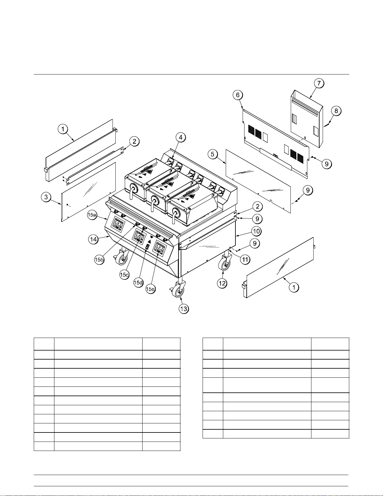
Section 4 Operator Parts Identification
C811 Exploded View
Figure 1
ITEM DESCRIPTION PART NO.
1 CAN-GREASE 073294
2 SLIDE-GREASE CAN 073293
3 PANEL-SIDE-LOWER*LEFT 073262
*4 KIT A.-GREASE SHIELD X78330-SER
5 PANEL-BACK LOWER 073432
6 PANEL A.-BACK SERVICE X73513
7 DEFLECTOR A.-FLUE X73510
8 SCREW-3/8-16X34SERR HWH 017328
9 SCREW-10-32X3/8SLTD TRUS 024298
10 PANEL-SIDE-LOWER*RIGHT 073261
11 NUT-JAM 1-1/2-12 (2 PCS) 073594
Models C811 & C813 Operator Parts Identification
ITEM DESCRIPTION PART NO.
12 CASTER-5" 7-5/8 STEM 078377
13 CASTER-GRILL 5” SWIVELLOC 073240
14 PANEL-FRONT-LOWER 073650
15 CONTROL A.-SWITCH
(INCLUDES 15a-15e)
15a PANELA.-FRONT UPPER X73373
15b BUTTON-OPERATOR-RED 076011
15c BUTTON-OPERATOR-BLACK 076012
15d SWITCH-ROCKER-DPST-10A 076989-WP
15e CONTROL-GRILL TOUCH PAD 073474
*NOTE: 1 KIT PER PLATEN
7
---
Page 12
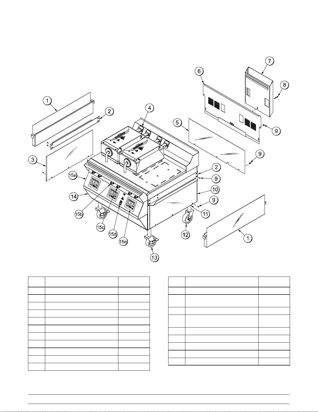
C813 Exploded View
ITEM DESCRIPTION PART NO.
1 CAN-GREASE 073294
2 SLIDE-GREASE CAN 073293
3 PANEL-SIDE-LOWER-LEFT 073262
*4 KIT A.-GREASE SHIELD X78330-SER
5 PANEL-BACK-LOWER 073432
6 PANEL A.-BACK SERVICE X73513
7 DEFLECTOR A.-FLUE X73510
8 SCREW-3/8-16X3/4 SERRATED 017328
9 SCREW-10-32X3/8SLTD TRUS 024298
10 PANEL-SIDE-LOWER-RIGHT 073261
11 NUT-JAM 1 1/2-12 STEEL 073594
Figure 2
8
ITEM DESCRIPTION PART NO.
12 CASTER-5" 7-5/8 STEM 078377
13 CASTER-GRILL 5" SWIVEL
W/LOCK
14 PANEL-FRONT-LOWER 073650
15 CONTROL A.-SWITCH
(INCLUDES ITEMS 15a-15e)
15a PANELA.-FRONT UPPER X73373
15b BUTTON-OPERATOR-RED 076011
15c BUTTON-OPERATOR-BLACK 076012
15d SWITCH-ROCKER-DPST-10A 076989-WP
15e CONTROL-GRILL-TOUCH PAD 073474
*NOTE: 1 KIT PER PLATEN
073240
X73525
Models C811 & C813Operator Parts Identification
Page 13
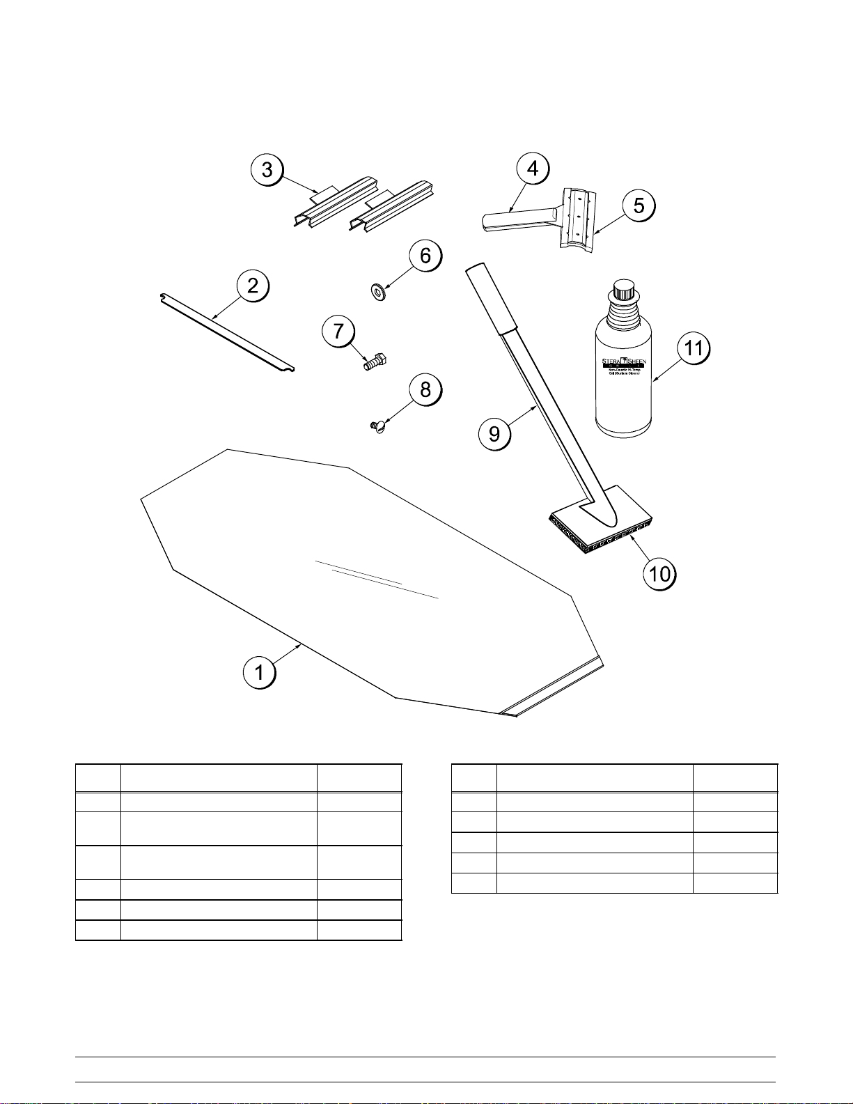
Accessories
Figure 3
ITEM DESCRIPTION PART NO.
1 SHEET-RELEASE (BOX 9) 073442
*2 RETAINER-SHEET RELEASE
(RETENTION BAR)
**3 CLIP-RELEASE MATERIAL
W/TAB
4 SCRAPER-TEFLON WIPER 075887
5 STRIP-REPLACEMENT 075888
6 WASHER-3/8 USS FLAT 000653
072845
072673
Models C811 & C813 Operator Parts Identification
ITEM DESCRIPTION PART NO.
7 SCREW-3/8-16X 1 HEX HEAD 001082
8 SCREW-10-32 X 3/8 SLTD 024298
9 HOLDER-CLEANING 073736
10 PAD-CLEANING 073737
11 CLEANER-STERA SHEEN 6 QT 073160-SAM
* SHOWN PER PLATEN
** SHOWN PER PLATEN
(NOTE: EXTRA CLIPS ARE SENT WITH GRILL)
101007
9
Page 14
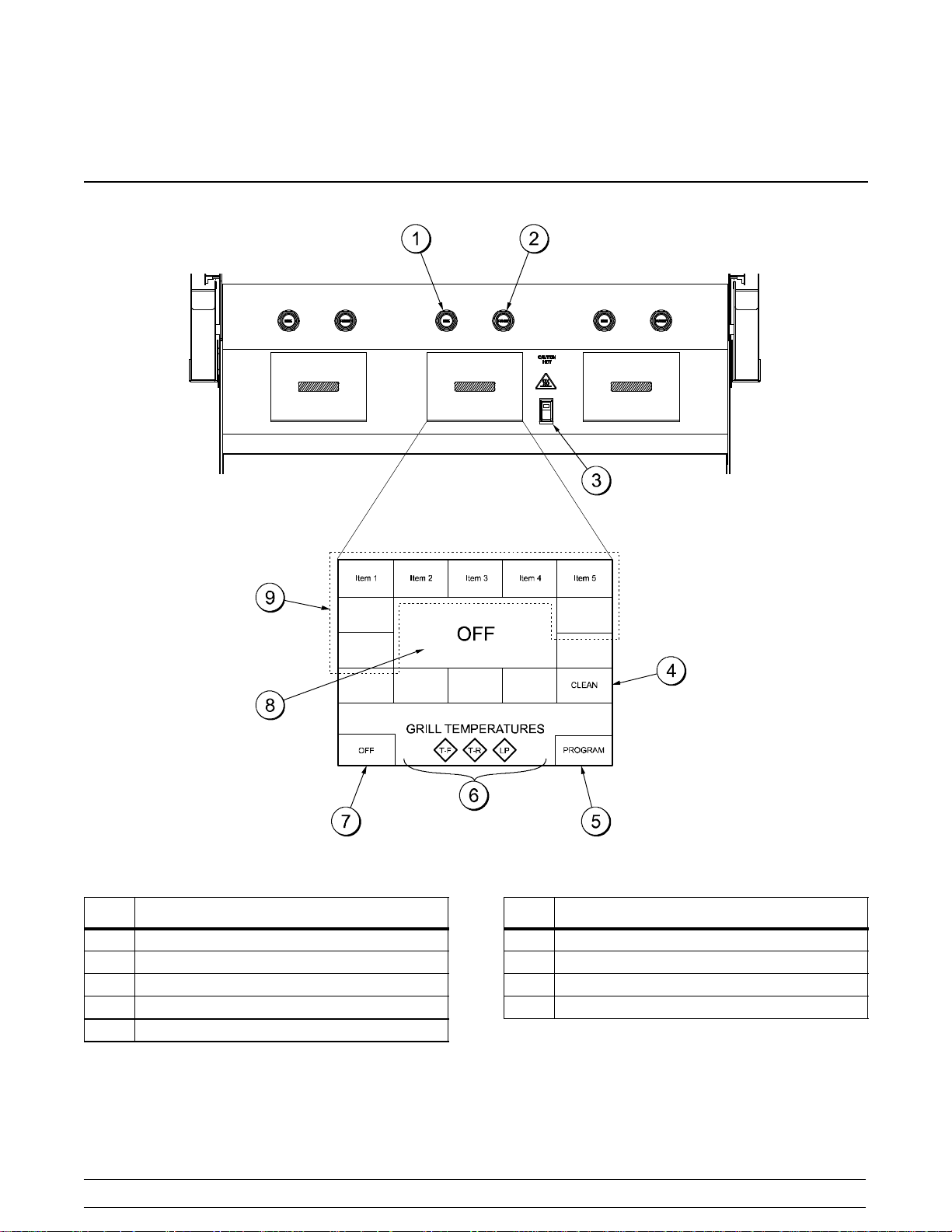
Section 5 Important: To the Operator
ITEM DESCRIPTION
1 RAISE BUTTON
2 STANDBY/COOK MODE BUTTON
3 POWER SWITCH
4 CLEAN MODE KEY
5 PROGRAM KEY
Figure 4
10
ITEM DESCRIPTION
6 TEMPERATURE INDICATOR LIGHTS
7 POWER KEY
8 FUNCTION DISPLAY
9 MENU SELECT KEYS
Models C811 & C813Important: To the Operator
Page 15
Section 6 Operating Procedures
The Model C811 has three independent upper
platens. The Model C813 has two independent
upper platens. These grills are capable of cooking a
variety of products and feature two cooking options.
They provide all of the features of a flat grill, as well
as the advantages of two-sided cooking.
Note: The three platen Model C811 has been
selected to illustrate the step-by-step procedures.
For grills equipped with less than three platens,
perform the following steps as appropriate for your
grill platen configuration.
Daily Opening Procedures
Before operating the grill, the release material
sheets must be installed on the upper platens.
Perform the following steps for installing release
material sheets:
CAUTION: Make sure the grill is COOL
before attempting to install or remove release
material sheets.
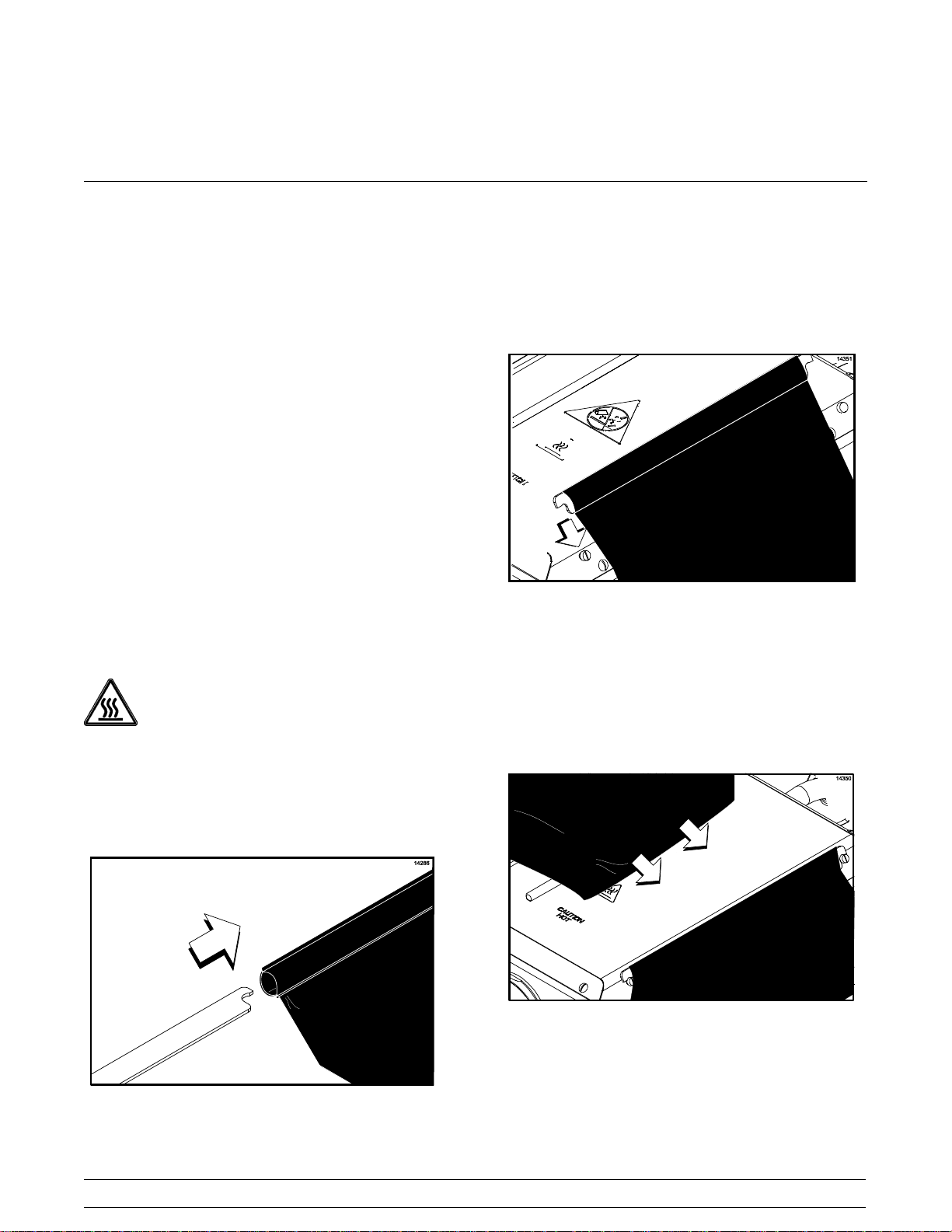
Step 2
Hook the release sheet retainer on the release
material shoulder screws at the top of the upper
platen.
Figure 6
Step 3
Hold the non-hemmed end of the release material
sheet. Gently pull the sheet tight, wrapping it around
the platen in a side-to-side manner.
Step 1
Slide the release sheet retainer through the hemmed
end of the release material sheet.
Figure 7
Note: Check the alignment of the release material
sheet and make sure it fits smoothly over the upper
Figure 5
Models C811 & C813 Operating Procedures
platen.
11
Page 16
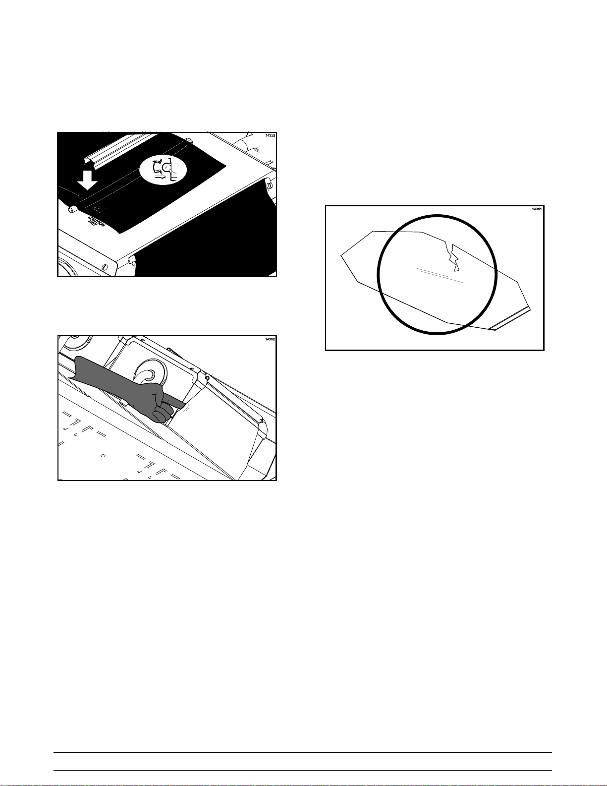
Step 4
Place the release material clips over the release
material sheet. Press them into place over the
release material bar at the top of the platen.
Figure 8
Step 5
Check the tightness of the release material sheet
against the upper platen.
The release material sheets must be
changed when:
S Product sticks to the release material.
S Carbon builds up, causing problems in taste
or appearance.
S There is a tear in the release material in the
cooking area.
Figure 10
Figure 9
Note: Installing the release material sheets too
tightly may cause premature failure of the sheet.
Step 6
Repeat steps 1 through 5 for the remaining upper
platen(s).
Note: It is not necessary to change the release
material sheets if small pin holes develop.
Note: Rotate and reverse the release material
sheets on a daily basis.
S The release material substance is worn from
the release material sheet.
Note: Temperature checks should only be
conducted with the release material sheets removed.
Note: Rotate and reverse the release material
sheets on a daily basis.
12
Models C811 & C813Operating Procedures
Page 17
Care of Release Material Sheets
S DO NOT fold or crease.
Figure 11
S DO NOT touch with any sharp object or
abrasive.
S DO NOT hose with hot water or soak in
water.
S DO NOT place under other objects.
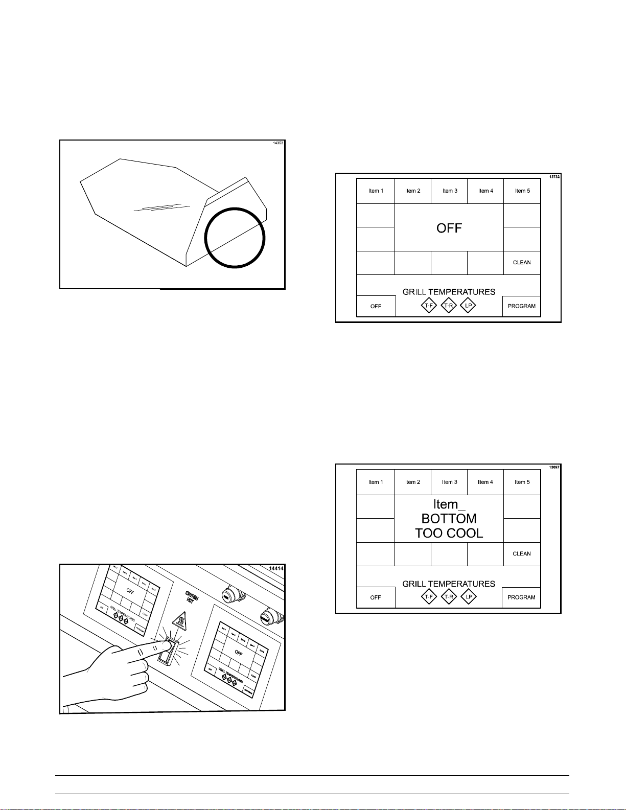
The control will display the word “INITIALIZATION”
for five seconds and then will enter the OFF mode,
displaying the message “OFF”. The temperature
indicators will not be illuminated. A tone will sound
for 20 seconds unless the operator touches the
display screen, raise button or the standby button.
Figure 13
Step 2
Touch a menu key on the control to start the grill.
The grill will start heating up to the proper
temperature. The control will display the selected
menu item and indicate “BOTTOM TOO COOL” and
“TOP TOO COOL”. The grill temperature indicators
will be illuminated in amber.
Start Up of the Grill
IMPORTANT! The lower grill surface and the
upper platen MUST BE CLEAN before starting
these procedures.
Step 1
Place the power switch in the ON position.
Figure 12
Figure 14
Note: If an ignition failure fault occurs upon start up,
press the center of the control. The control will
display “OFF”. Refer to problem #2, items a, b, and c
of the Gas Grill Troubleshooting Guide on page 31.
After five minutes has elapsed, press the menu key
again. If the ignition failure fault was not resolved,
please call your authorized service technician.
Models C811 & C813 Operating Procedures
13
Page 18
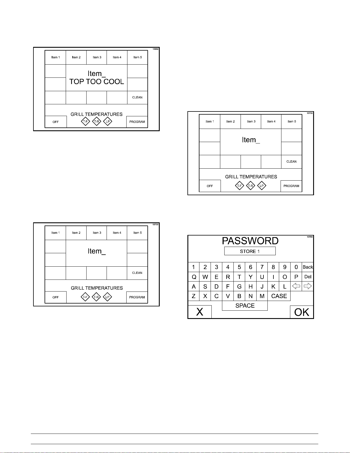
Figure 15
When the grill is at the proper temperature, the
temperature statements will no longer display and
the temperature indicators will be illuminated in
green.
Programming Menu Items
To enter the Program Mode, the grill control must be
in the OFF or IDLE mode.
Step 1
Press and hold the PROGRAM key for
approximately five seconds to enter the Program
Mode.
Figure 17
Step 2
The PASSWORD screen will appear. Enter the
following password: STORE1.PresstheOKkey.
Figure 16
14
Figure 18
Models C811 & C813Operating Procedures
Page 19
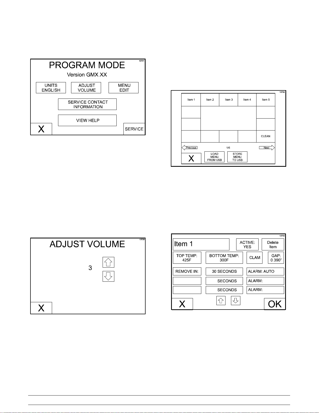
Step 3
The PROGRAM MODE screen will appear.
Figure 19
UNITS Key
MENU EDIT Key
The MENU EDIT key is used to program a menu
item. When the MENU EDIT key is pressed, the
following screen will display.
The UNITS key is used to select either English or
metric units of measure. The UNITS key toggles
between F and C with each key press.
ADJUST VOLUME Key
The ADJUST VOLUME key displays the current
volume. To increase or decrease the volume, use
the UP and DOWN arrow keys.
Figure 20
Figure 21
If there is more than one screen of menu items,
press the Previous or Next arrow keys to access the
other menu items.
Press the menu item key to be programmed. The
following screen will display.
Figure 22
Models C811 & C813 Operating Procedures
15
Page 20
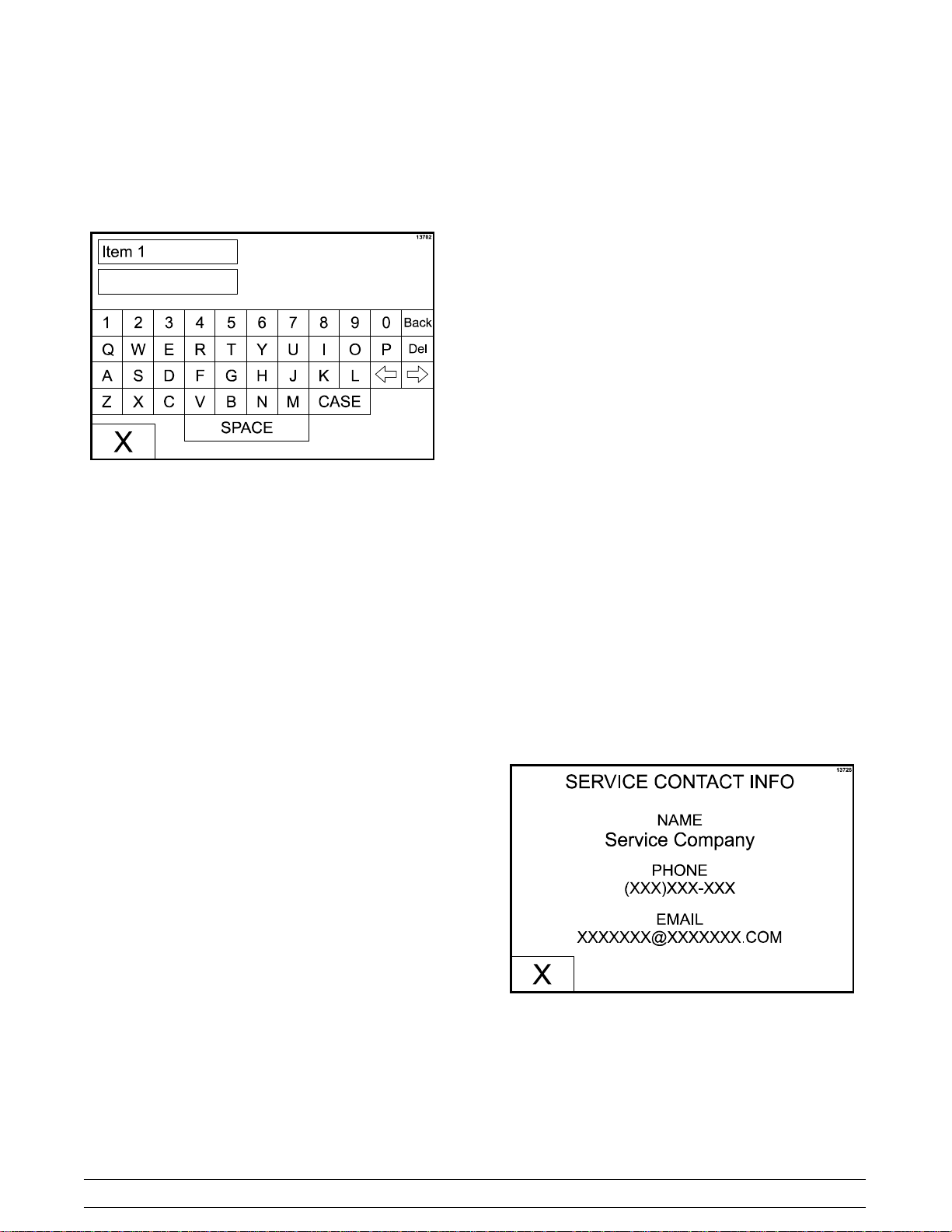
To edit a menu item, press the menu item key to
bring up a virtual keyboard. Type in the desired
name (up to 8 characters per line) and then press
the “X” key to return to the previous screen.
Figure 23
ACTIVE: YES or NO. This key displays the current
selection. Pressing the key toggles to the opposite
selection. Selecting YES will display the menu item
on the main display screen.
TOP TEMP: This key displays the current set point
temperature for the platen. To increase or decrease
the temperature, use the UP and DOWN arrow keys.
MULTIPLE TIMING FUNCTIONS: There is one
timing function for clam items and a maximum of 3
timing functions for each flat menu item. Each
function has a set of parameters associated with it.
The function currently associated with the menu item
is displayed. Pressing either function 1, function 2, or
function 3 will bring up the next function in the list.
The functions provided are:
S REMOVE IN
S TURN IN
S SEAR IN
ALARM AUTO/MANUAL: This key displays the
current status of the alarm mode. Pressing the key
toggles the mode to the opposite selection.
If ALARM AUTO is selected, the alarm will
automatically stop after five seconds has elapsed.
Selecting ALARM MANUAL requires the operator
touch anywhere on the display screen or the raise or
standby buttons to stop the alarm.
XXX SECONDS: This key displays the time
associated with that menu item in seconds. To
increase or decrease the seconds setting, use the
UP and DOWN arrow keys.
Upon completion of all programming selections,
save the selections by pressing the OK key. To
return to the main display screen without saving the
programming selections, press the X key.
BOTTOM TEMP: This key displays the current set
point temperature for the lower grill surface. To
increase or decrease the temperature, use the UP
and DOWN arrow keys.
Note: When setting the temperatures for a given
item, the limits are 150°F to 450°F (66°C to 232°C)
for the upper platen and 150°F to 400°F (66°C to
204°C) for the lower grill surface. If the temperatures
are set lower or higher than the temperature limits,
the set point at the control will default to 150°F and
450°F (66°C and 232°C) respectively.
CLAM/FLAT: This key displays the current setting
(CLAM or FLAT) associated with that function.
Pressing the key toggles the mode to the opposite
selection.
GAP: This key is only active if CLAM has been
selected. The key displays the platen gap (in inches
or mm) associated with the FUNCTION. To increase
or decrease the gap setting, use the UP and DOWN
arrow keys.
SERVICE CONTACT INFORMATION Key
Press the SERVICE CONTACT INFORMATION key
to view the programmed service contact information.
Figure 24
VIEW HELP Key
The View Help key is not functional at this time
(future development).
16
Models C811 & C813Operating Procedures
Page 21
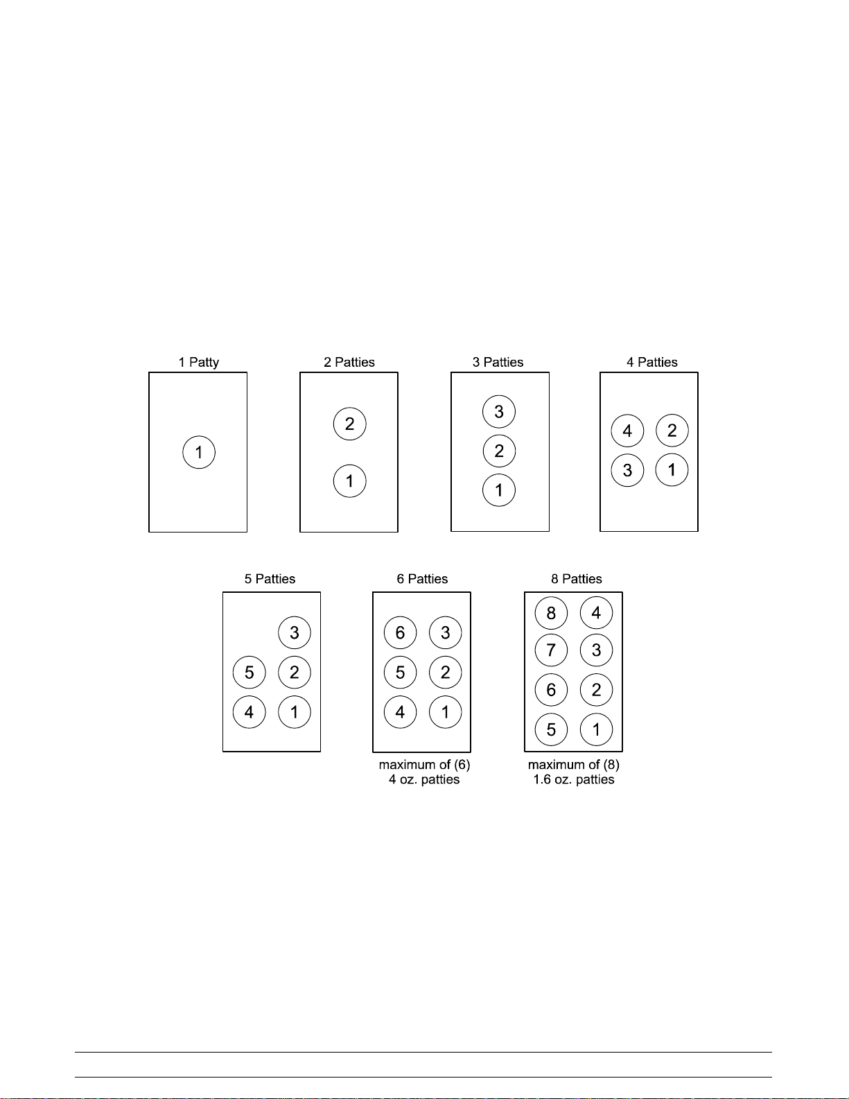
Patty Placement
Placement procedures of meat products must be
followed on the grill. Meat must be placed on the
lower grill surface front to back. When the cook cycle
is complete, the upper platen will raise.
Note: It is very important that all patties be
removed from the lower grill surface in the same
sequence that they were placed before cooking.
Patties must be removed immediately after the
upper platen has been raised to the OPEN position
and after the meat has been seasoned.
Patties are generally placed two at a time from front to back of grill and right to left. The removal order of the
patties is shown in the diagrams by the number shown in the center of each patty.
Models C811 & C813 Operating Procedures
17
Page 22
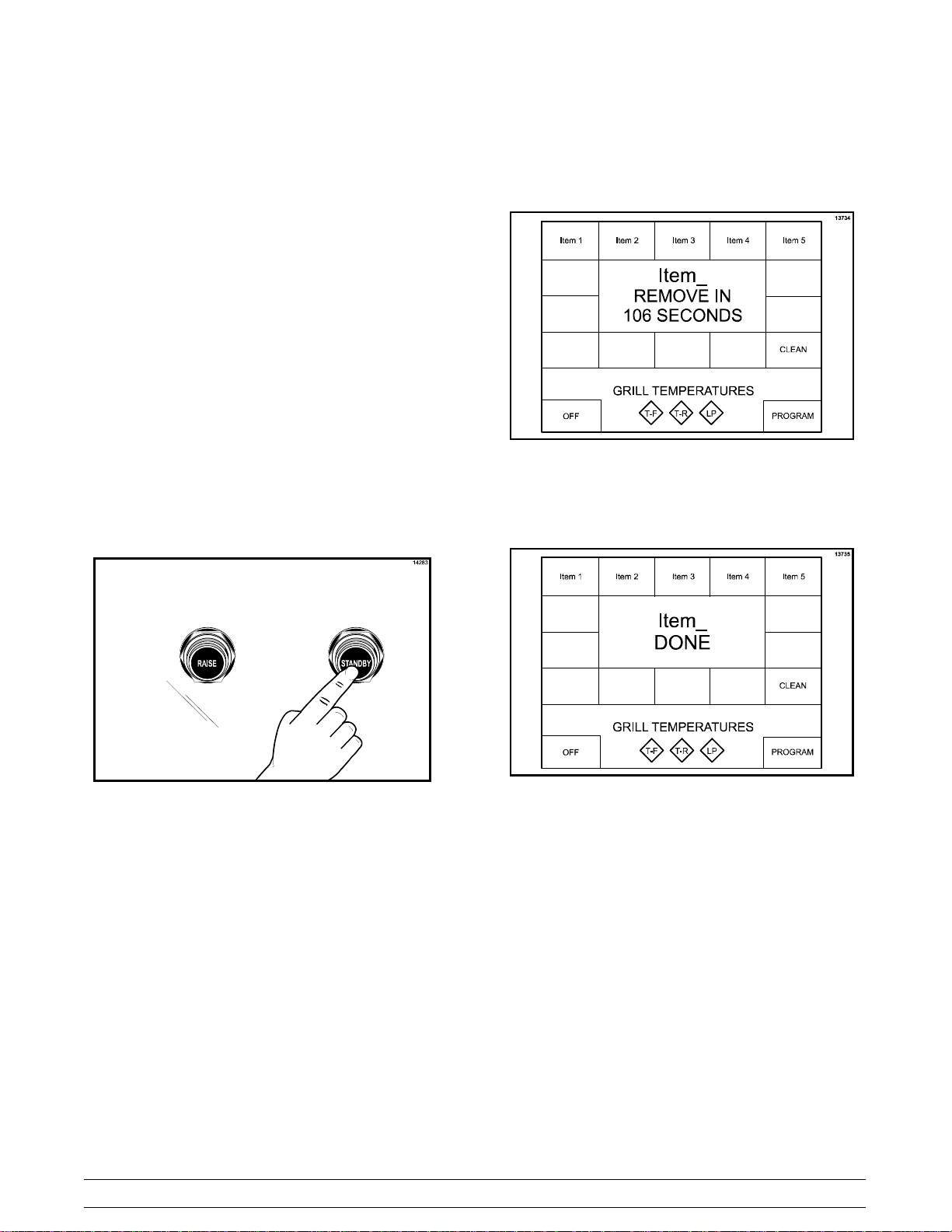
Operating Procedures
Cooking Product
Step 1
Select the menu item to be cooked. The grill is at the
correct temperature if the control does not display
any temperature statements and the grill
temperature indicators are green.
Step 2
Quickly place the product on the lower grill surface,
from front to back.
During the cooking cycle, the display will show the
name of the current menu item, “REMOVE IN”, and
the time remaining until the product should be
removed.
Figure 26
Step 3
Press the STANDBY button once.
Figure 25
The display reads “MOVING DOWN” as the platen
lowers to the cook surface.
At the end of the cook cycle, the control will display
“DONE”, a tone will sound, and the platen will
automatically raise.
Figure 27
Note: To cancel a cook cycle at any time, press the
RAISE button. A tone will sound and the display will
read “CANCEL” for five seconds and then enter an
IDLE mode.
18
Models C811 & C813Operating Procedures
Page 23
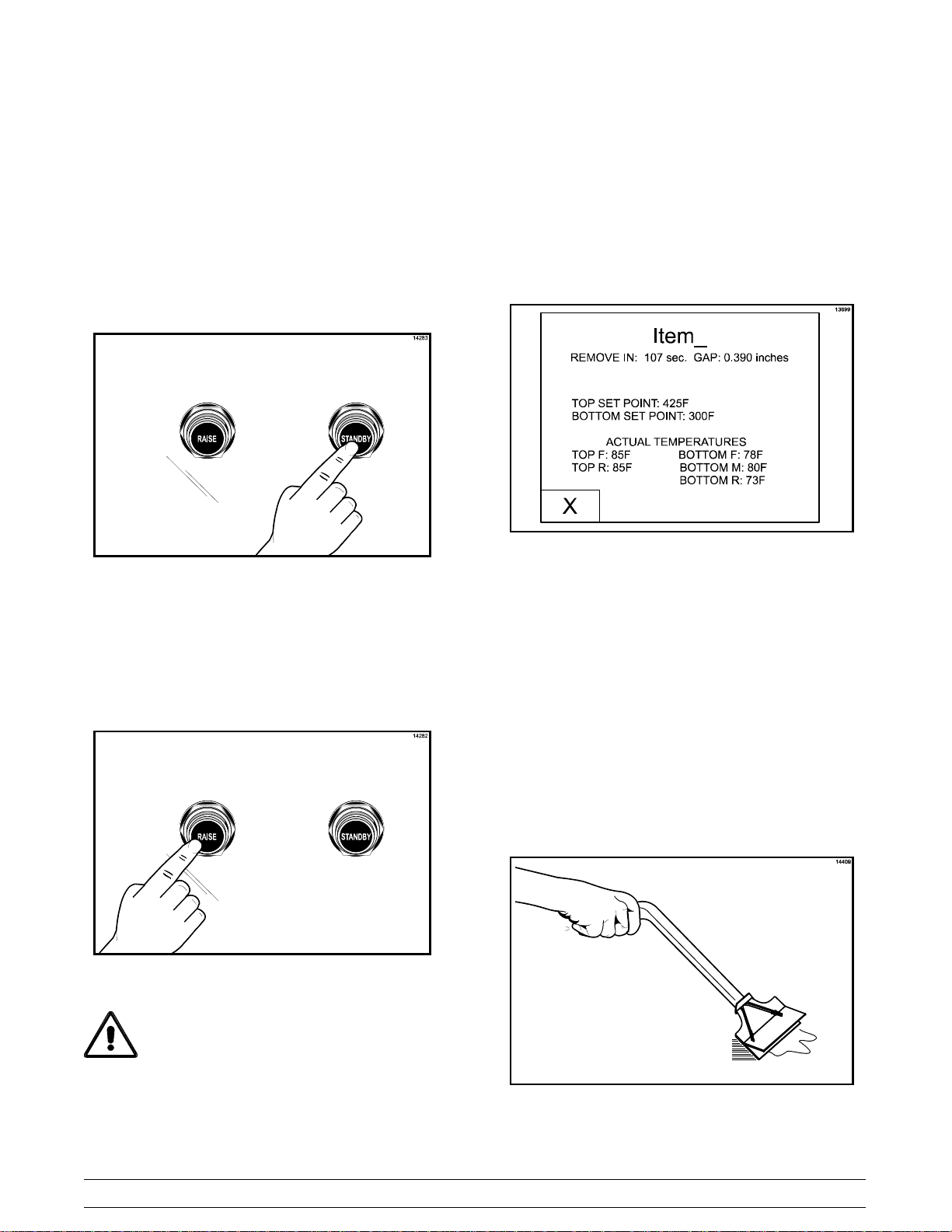
Standby Procedures
Menu Parameters
Whenever the grill is idle and product is not being
cooked, the upper platen must be placed in the
STANDBY position.
Step 1
To place the upper platen in the STANDBY position,
press the STANDBY button twice from the open
position.
Figure 28
The control will display “GOING TO STANDBY” and
then change to display “STANDBY”.
Step 2
To raise the upper platen to the OPEN position to
resume cooking, press the RAISE button.
To view the settings and actual temperatures for the
current item, press and hold the menu item key a
minimum of 5 seconds. The screen will display the
cook time, gap setting, temperature set points and
actual temperature readings for each zone for that
menu item.
Figure 30
If a key is not pressed for 20 seconds, the grill
control will return to the normal display. Pushing the
“X” key will bring the display back to the main display
page.
Cleaning After Each Run of Product
Step 1
Using the grill scraper, scrape the grease on the
lower grill surface from front to back. Do not scrape
across the rear of the lower grill surface with the grill
scraper.
Figure 29
CAUTION: Never use force to raise the
upper platen. Damage to components may
result. Only use the RAISE button to open the
upper platen!
Models C811 & C813 Operating Procedures
19
Figure 31
Page 24
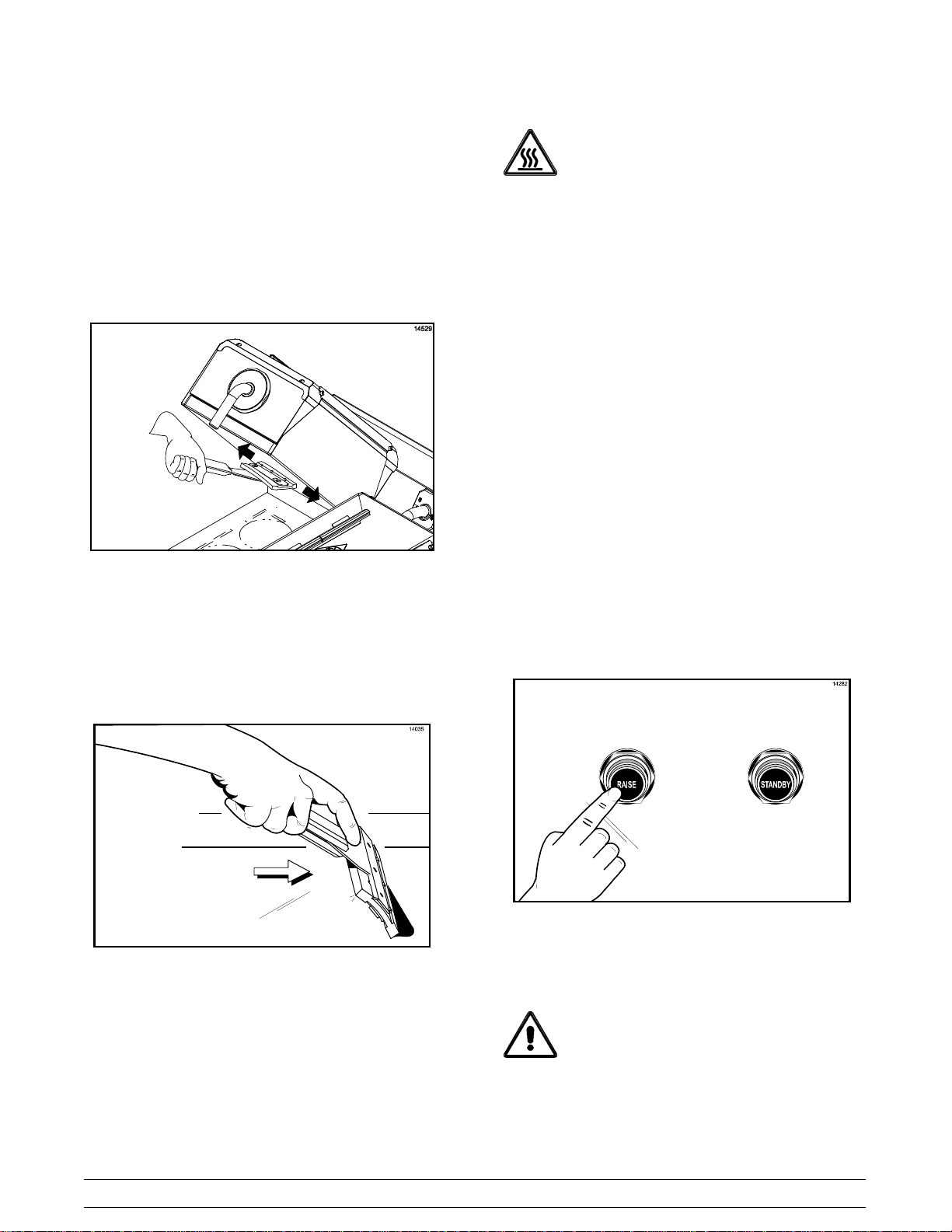
Step 2
Use the wiper squeegee to clean the release
material sheet on the upper platen. Use a diagonal
motion to clean the sheet. Hold the handle at a slight
upward angle, with the wiper end facing downward.
(Note: Do not use excessive pressure when wiping
the release material sheet with the squeegee. Using
excessive pressure can scratch or tear the release
material sheet.)
CAUTION: The upper platen surface is
very HOT! To prevent burn injuries, use extreme
caution when wiping the release material sheet.
Daily Cleaning Procedures
Note: The three platen Model C811 has been
selected to illustrate the step-by-step procedures.
For grills equipped with less than three platens,
perform the following steps as appropriate for your
grill platen configuration.
Figure 32
Step 3
Using the wiper squeegee, push the grease at the
rear of the lower grill surface into the grease can. Do
not use the grill scraper for this step.
Step 4
Use a cloth to clean the back splash plate and the
bullnose areas as needed during operation.
Note: To increase the life of the release material
sheet, wipe it with a damp, folded cloth a minimum
of four times every hour.
Step 1
Raise the upper platen to the OPEN position by
pressing the red RAISE button.
Figure 33
CAUTION: Never use force to raise the
upper platen. Damage to components may
result. Only use the RAISE button to open the
upper platen!
20
Models C811 & C813Operating Procedures
Page 25
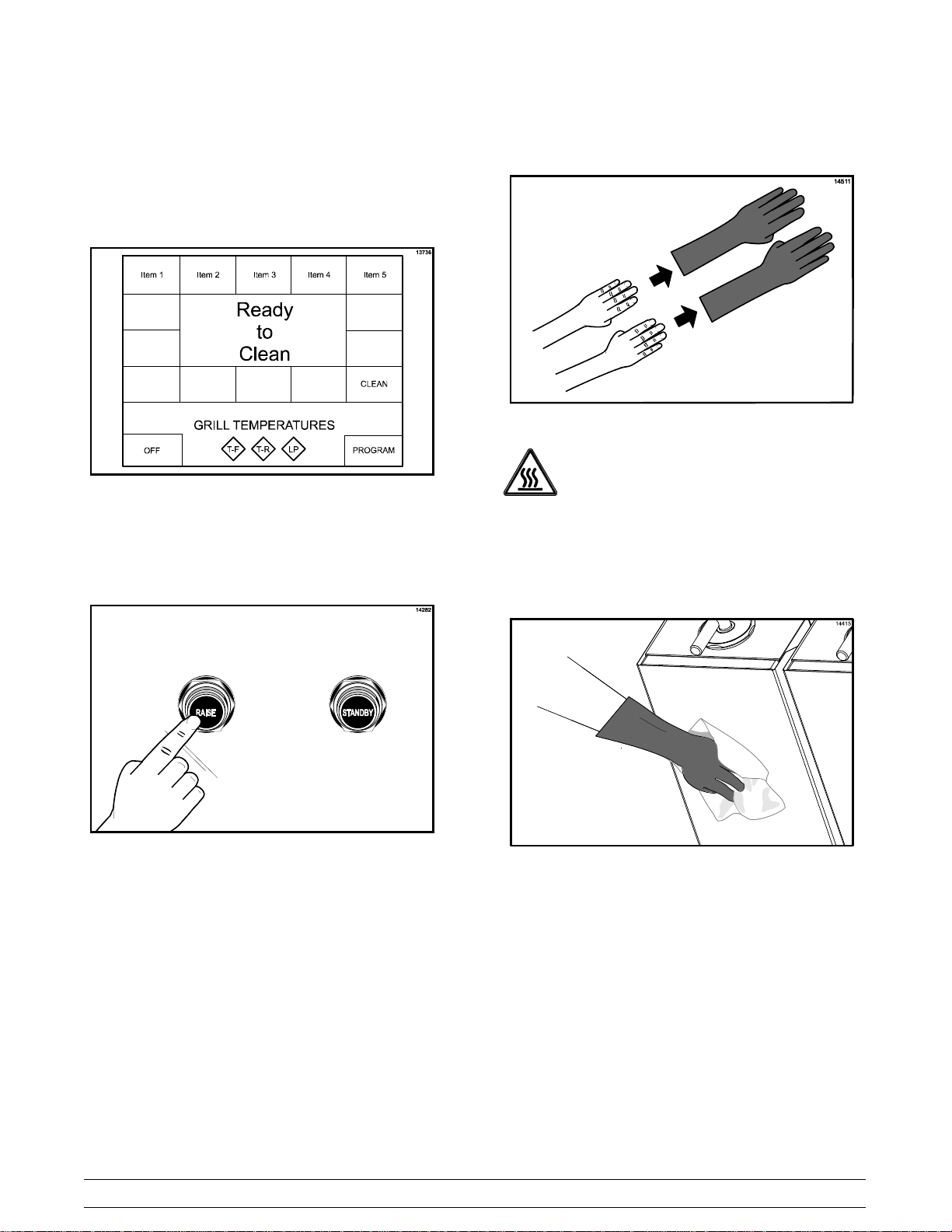
Step 2
Press the CLEAN key. When the cook surfaces
reach the proper temperature for cleaning, an alarm
will sound and the message “READY TO CLEAN”
will be displayed.
Figure 34
Step 3
Press the RAISE button to cancel the alarm.
Step 4
Put on heat-resistant gloves.
Figure 36
CAUTION: The upper platen surface and
release material sheets are very hot. To prevent
burn injuries, use extreme care.
Step 5
Wipe the exposed surface of the release material
sheets with a clean, wet cloth.
Figure 35
Models C811 & C813 Operating Procedures
21
Figure 37
Page 26
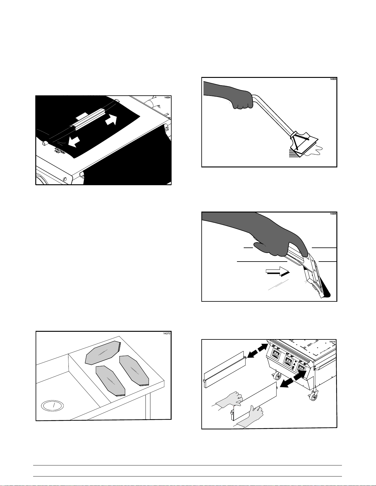
Step 6
Remove the release material clip, release sheet
retainer, and the release material sheet. Take these
parts to the sink to be washed and rinsed.
Figure 38
Step 7
Repeat steps 1 through 6 for the remaining upper
platen(s).
Step 10
Scrape the lower grill surface with the grill scraper,
from front to back.
Figure 40
Step 11
Use the wiper squeegee to push residual grease into
the grease cans.
Step 8
Wash and rinse the clips and retainers in the sink.
Set them aside for future use.
Step 9
Set the release material sheets aside on a clean, flat
surface next to the sink until further cleaning is
performed. DO NOT fold, crease, or place them on
sharp objects.
Figure 41
Step 12
Remove, empty, and reinstall the grease cans.
Figure 39
22
Figure 42
Models C811 & C813Operating Procedures
Page 27
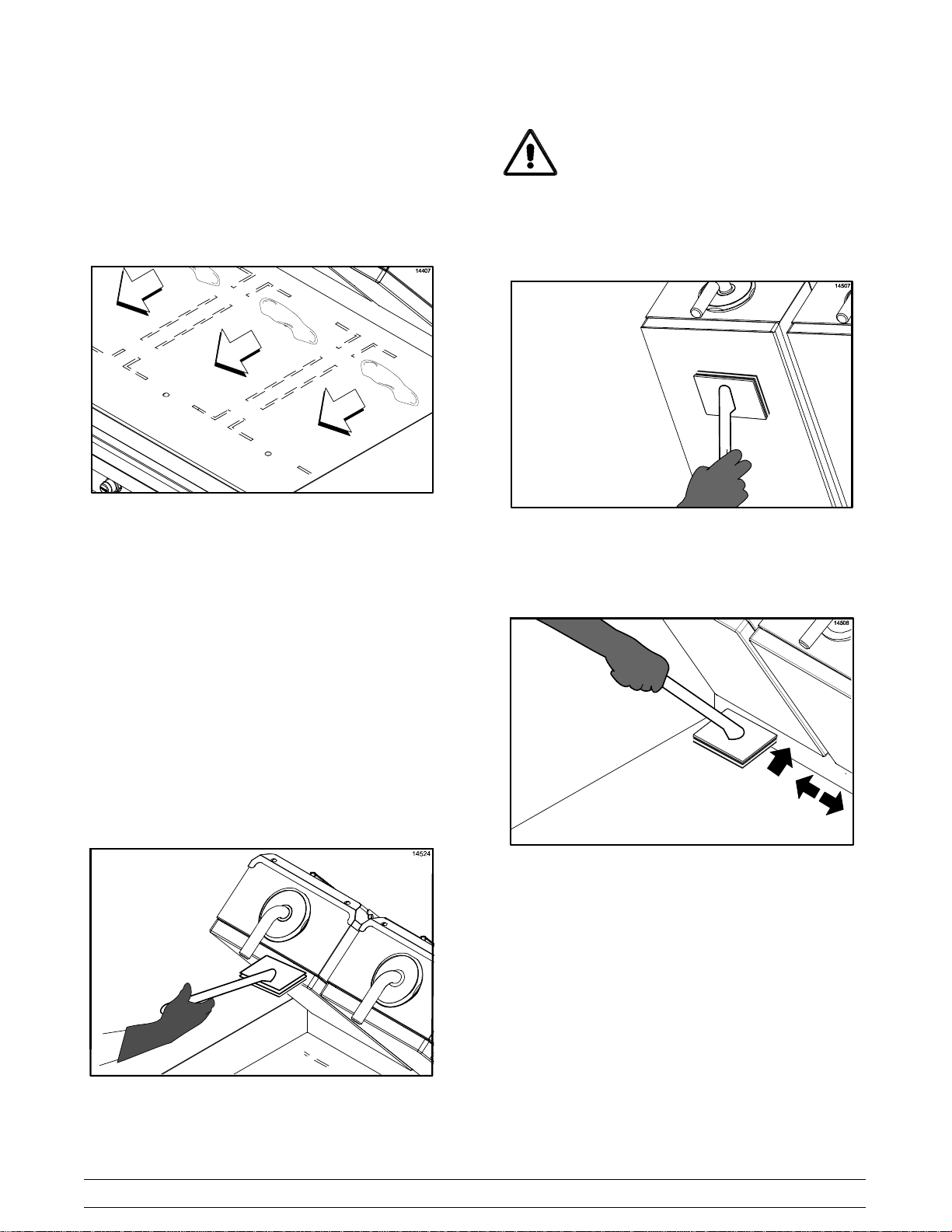
Step 13
Using an approved high temperature grill cleaner,
(examples: 3M Scotch-Brite™ Quick Clean Griddle
Liquid or Kay® Sizzle® Grill & Bun Toaster Cleaner)
pour approximately 3 oz. (90 ml) onto each 12” (305
mm) cook zone.
DO NOT use metal scrapers, abrasive
pads, screens, or wire brushes. Damage to
components may result.
Step 17
Apply grill cleaner to the platen surfaces.
Figure 43
Step 14
Firmly attach a non-abrasive pad to the pad holder.
(Note: The pad must not contain any ceramic
particles.)
Step 15
Dip the non-abrasive pad into the grill cleaner.
IMPORTANT: DO NOT SCRUB while applying
grill cleaner in the following steps:
Step 16
Apply grill cleaner to the front side of the upper
platens.
Figure 45
Step 18
Apply grill cleaner to the back side of the upper
platens.
Figure 46
Step 19
Apply grill cleaner to the outer edges of the right and
left platens.
Step 20
C811: Press the STANDBY button to lower the
center platen.
C813: Press the STANDBY button to lower one of
the platens, if needed.
Step 21
C811: Apply grill cleaner to both sides of the center
Figure 44
Models C811 & C813 Operating Procedures
platen.
23
Page 28
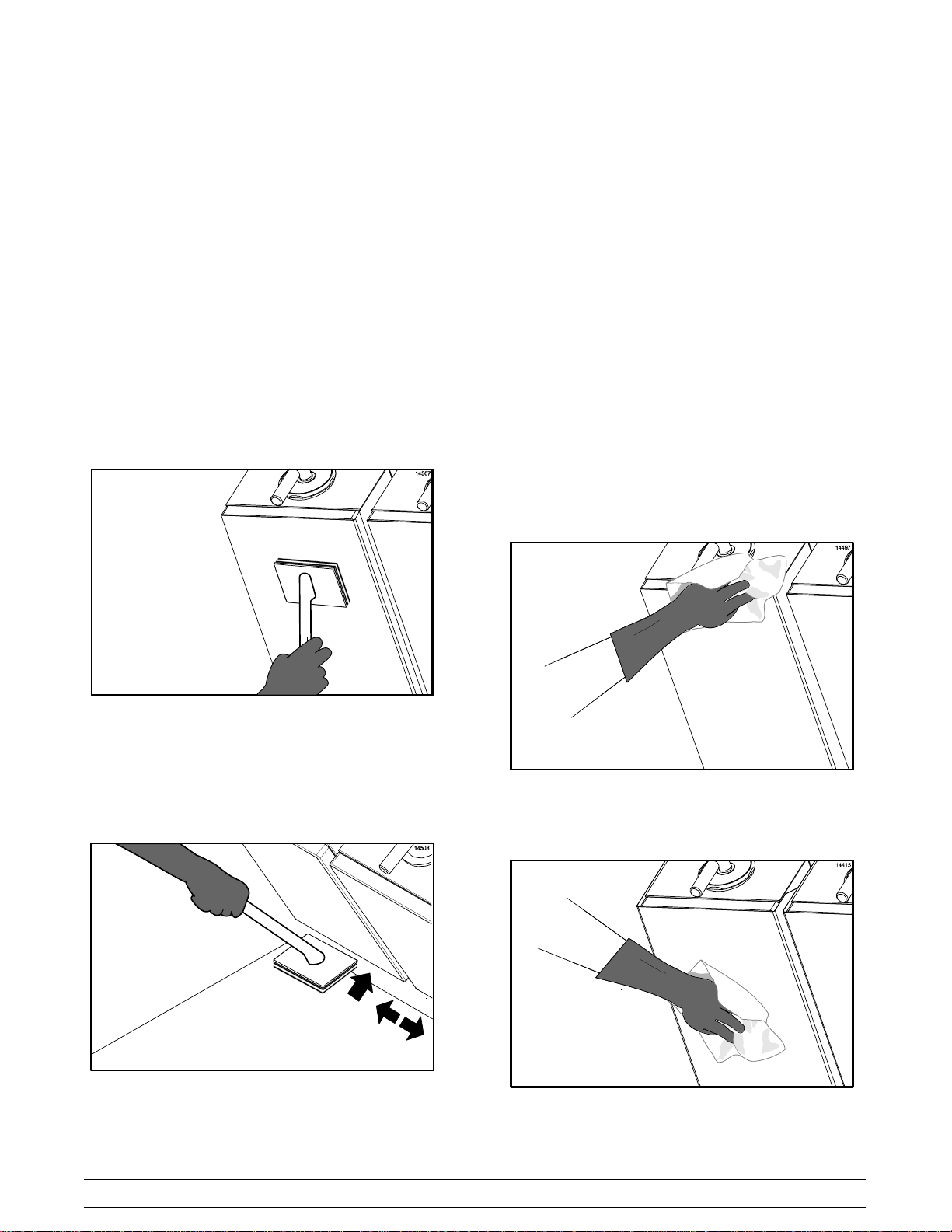
Step 22
Apply grill cleaner to the inner edges of the right and
left platens.
Step 27
Lightly scrub the outer edges of the right and left
platens.
Step 23
Press the RAISE button to raise the lowered platen.
Step 24
Lightly scrub the front side of the platens with the
non-abrasive pad until all soil has been liquified by
the grill cleaner. For stubborn soils, apply additional
grill cleaner and lightly scrub. Do not rinse the
platens at this time.
Step 25
Lightly scrub the platen surfaces.
Step 28
C811: Press the STANDBY button to lower the
center platen.
C813: Press the STANDBY button to lower one of
the platens, if needed.
Step 29
C811: Lightly scrub both sides of the center platen.
Step 30
Lightly scrub the inner edges of the right and left
platens.
Step 31
Press the RAISE button to raise the lowered platen.
Step 32
With a clean, wet cloth, rinse the front, sides, and
back of the platen surfaces.
Figure 47
Step 26
Lightly scrub the back side of the upper platens.
Figure 48
Step 33
With a clean, wet cloth, rinse the platen cook
surfaces.
Figure 49
24
Models C811 & C813Operating Procedures
Page 29
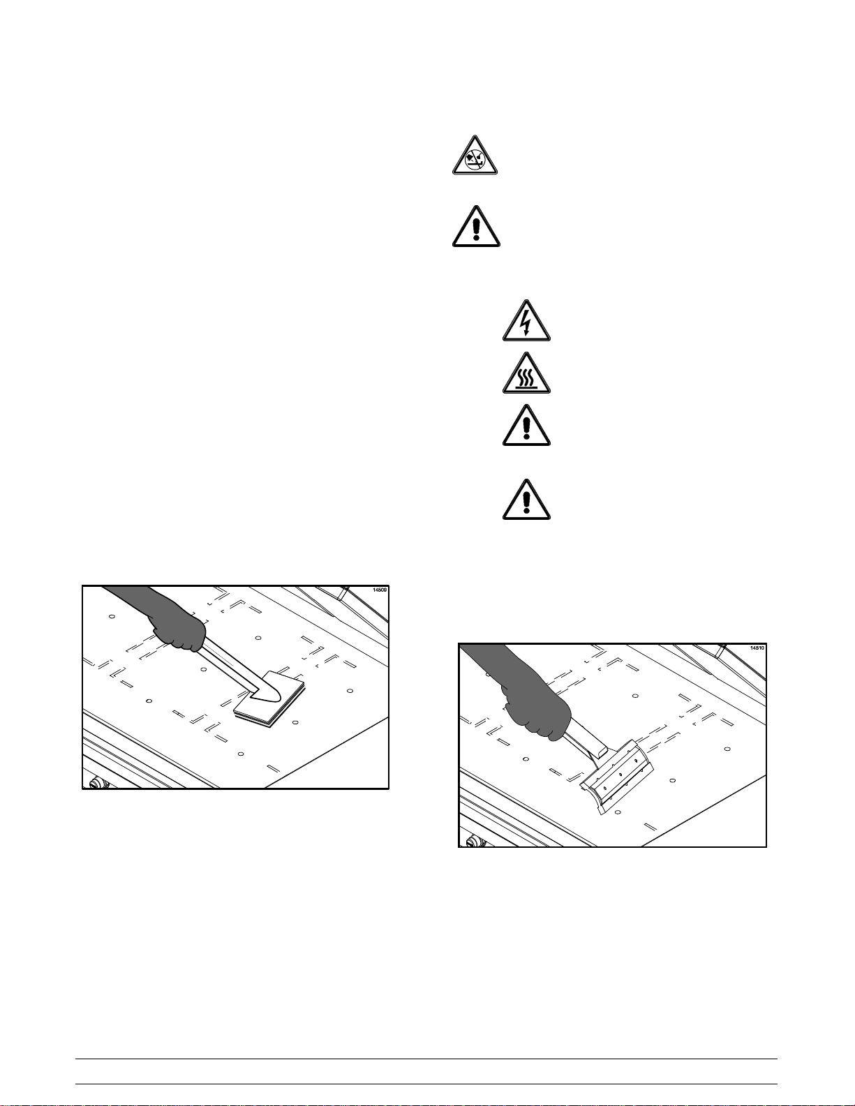
Step 34
C811: Press the STANDBY button to lower the
center platen.
C813: Press the STANDBY button to lower one of
the platens, if needed.
Step 35
C811: With a clean, wet cloth, rinse both sides of the
center platen.
Step 36
With a clean, wet cloth, rinse the inner edges of the
right and left platens.
IMPORTANT!
DO NOT use a jet of water to clean or rinse
the grill.
DO NOT use cold water or ice to cool the
upper platen or the lower cook surface.
Failure to follow these instructions may result in:
Step 37
Press the RAISE button to raise the lowered platen.
Step 38
With a clean, wet cloth, wipe the exterior of all the
platens, especially behind the rear of the upper
platens (next to the arm assembly).
Step 39
Starting at the back of the lower grill, spread the
remaining grill cleaner over the entire surface. Do
not scrub while applying product.
Step 40
Lightly scrub the surface with the non-abrasive pad
until all soil has been liquified by the grill cleaner.
S serious electrical shock
S burns from hot steam
S liquid collecting inside the grill and
destroying electrical components
S damaged cook surfaces
Step 41
Carefully pour warm water on the lower grill surface,
starting from the back to the front. Use the squeegee
to remove the cleaner from the grill surface.
Figure 50
Note: The rear of the upper platen, as well as the
tubular arm, can easily be wiped from the front of the
unit. If cleaning is performed on a daily basis, there
should be no carbon build-up.
Models C811 & C813 Operating Procedures
25
Figure 51
Page 30
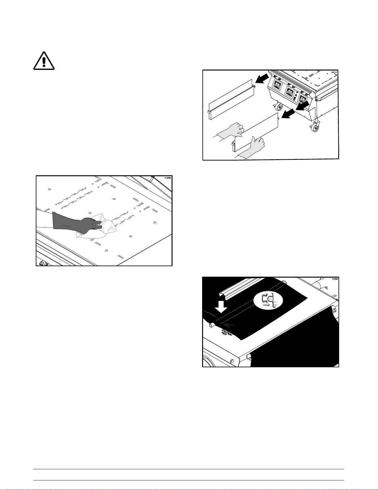
To avoid damaging the grill:
S Never use grill screens on the upper platen
or the lower grill surface.
S Never use any abrasives or cleaners other
than the approved cleaner.
S Never allow the grill scraper or the abrasive
cleaning materials to come in contact with
the release material.
Step 42
Pour a small amount of lukewarm water on a clean,
wet cloth over the lower grill surface and wipe off the
residue.
Step 46
Remove and empty the grease cans.
Figure 53
Step 47
Wash, rinse, and reinstall the grease cans.
24 Hour Stores Only:
Figure 52
Step 43
Wipe the lower grill surface with a clean, wet cloth.
Repeat until no visible soil remains.
Step 44
On a clean, sanitized, flat surface next to the sink,
clean both sides of the release material sheets by
gently wiping them with a clean, sanitized cloth.
Step 45
Place the release material sheets on a clean,
sanitized, flat surface to air dry overnight.
Step 47
Re-install the release material sheets on the
opposite side than previously used. Secure the
sheets with the release material clips and retainers.
Start up the grill per instructions starting on page 11.
Figure 54
26
Models C811 & C813Operating Procedures
Page 31
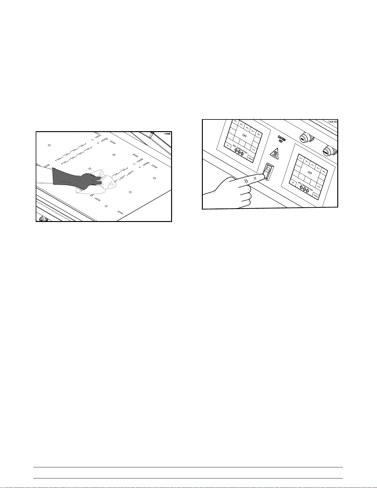
Non-24 Hour Stores Only:
Step 48
Wipe all areas with a clean, wet cloth.
Step 49
Wipe all exterior panels.
Step 50
Apply a light coat of vegetable oil to the entire lower
grill surface.
Step 51
Leave the upper platens in the OPEN position
overnight.
Step 52
Place the power switch in the OFF position.
Figure 55
Figure 56
Models C811 & C813 Operating Procedures
27
Page 32
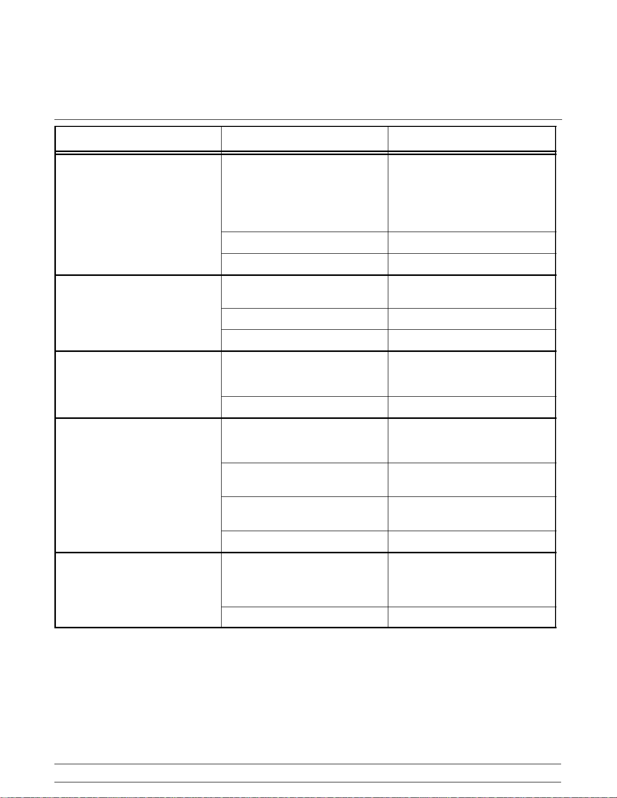
Section 7 Troubleshooting Guide
PROBLEM PROBABLE CAUSE REMEDY
1. One side of the grill will not
heat. The control will display
the message, “FAULTY
ELEMENT OR SHORTED
PROBE” after the TOO COOL
timer has elapsed.
2. One heat zone will not heat.
(Display reads “TOO COOL”.)
3. One of the heat zones is
overheating. (Display reads
“TOO HOT”.)
4. The grill will not turn on when
power switch is placed in the
ON position.
a. The heater is faulty. a. Call a service technician.
b. The high limit switch is faulty. b. Call a service technician.
c. The solid state relay is faulty. c. Call a service technician.
a. The interface board is faulty. a. Call a service technician.
b. The solid state relay is faulty. b. Call a service technician.
c. The control harness is faulty. c. Call a service technician.
a. The interface board is faulty. a. Call a service technician.
b. The solid state relay is faulty. b. Call a service technician.
a. The restaurant circuit breaker
has been tripped.
a. Reset the circuit breaker.
5. The upper platen will not stay
in the STANDBY mode, but will
stay in the COOK position.
b. The control cord is not
connected properly.
c. The fuse in the control box is
faulty.
d. The power switch is faulty. d. Call a service technician.
a. Incorrect use of the STANDBY
button.
b. Faulty wire connections. b. Call a service technician.
b. Reconnect the cord.
c. Call a service technician.
a. Press the STANDBY button
within five seconds of lowering
theplatenintotheCOOK
position.
28
Models C811 & C813Troubleshooting Guide
Page 33
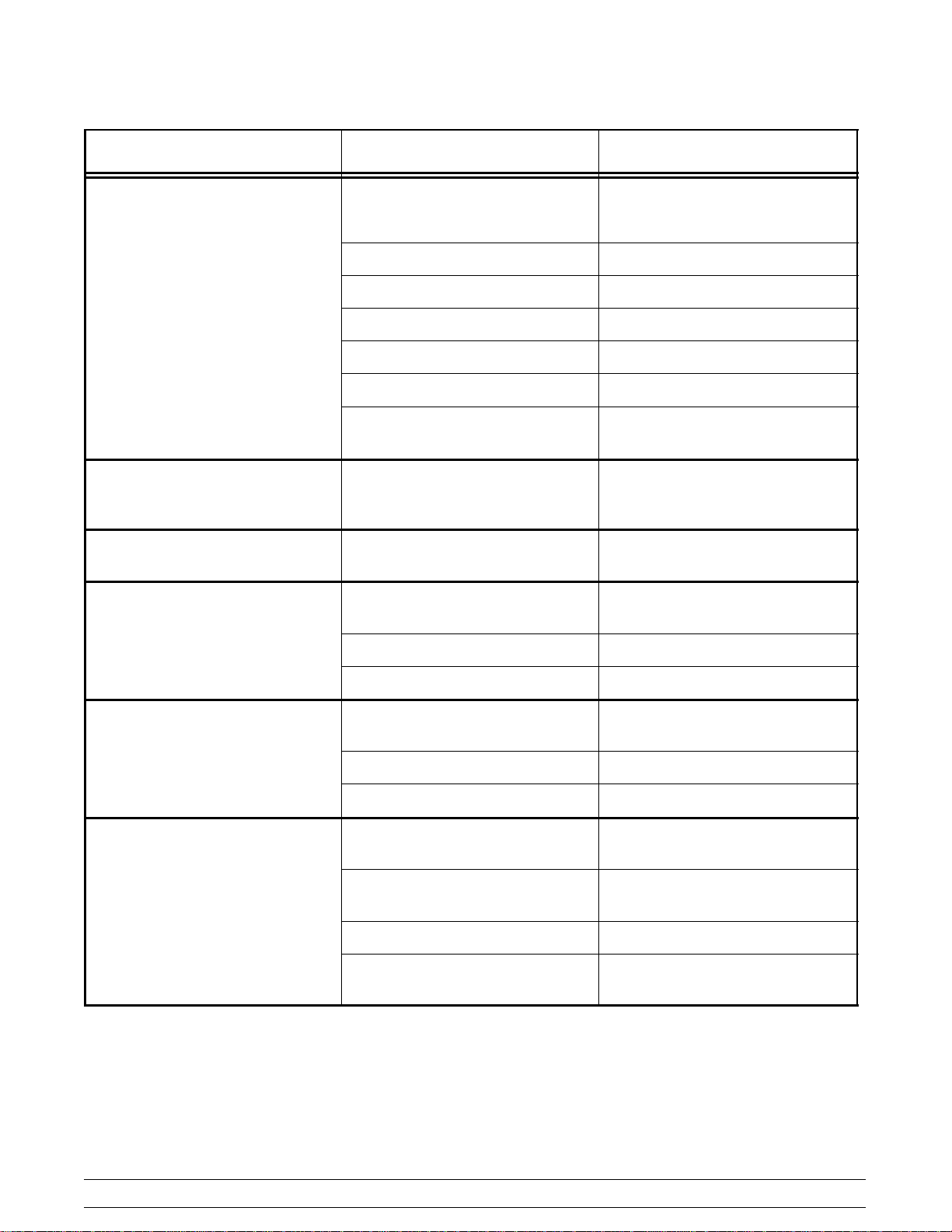
PROBLEM PROBABLE CAUSE REMEDY
6. The upper platen will not stay
in the COOK or STANDBY
position.
7. The upper platen will not stay
in the COOK position, but will
stay in the STANDBY mode.
8. The upper platen opens too
rapidly.
9. The display reads “PLATEN
NOT LATCHED”.
a. Temperature is insufficient to
satisfy the indicator LED's.
b. The control harness is faulty. b. Call a service technician.
c. The interface board is faulty. c. Call a service technician.
d. The latch switch is faulty. d. Call a service technician.
e. The latch solenoid is faulty. e. Call a service technician.
f. The processor control is faulty. f. Call a service technician.
g. The pneumatic system is
faulty.
a. The processor control is not set
properly.
a. The orifice/check valve is
incorrect or missing.
a. The pneumatic system is
faulty.
a. Wait until the indicator LED's
turn green.
g. Call a service technician.
a. Call a service technician.
a. Call a service technician.
a. Call a service technician.
10. The display reads “UPPER
PLATEN STUCK”.
11. The platen will not lower to
preset gap height.
b. The latch switch is faulty. b. Call a service technician.
c. The latch solenoid is faulty. c. Call a service technician.
a. The arm bearings are dirty. a. Call a service technician.
b. The air cylinder is faulty. b. Call a service technician.
c. Plugged air lines to cylinders. c. Call a service technician.
a. Defective motors and cables. a. Call a service technician.
b. Defective motor interface
board.
c. Loose harness connections. c. Call a service technician.
d. Defective main display
controller.
b. Call a service technician.
d. Call a service technician.
Models C811 & C813 Troubleshooting Guide
29
Page 34
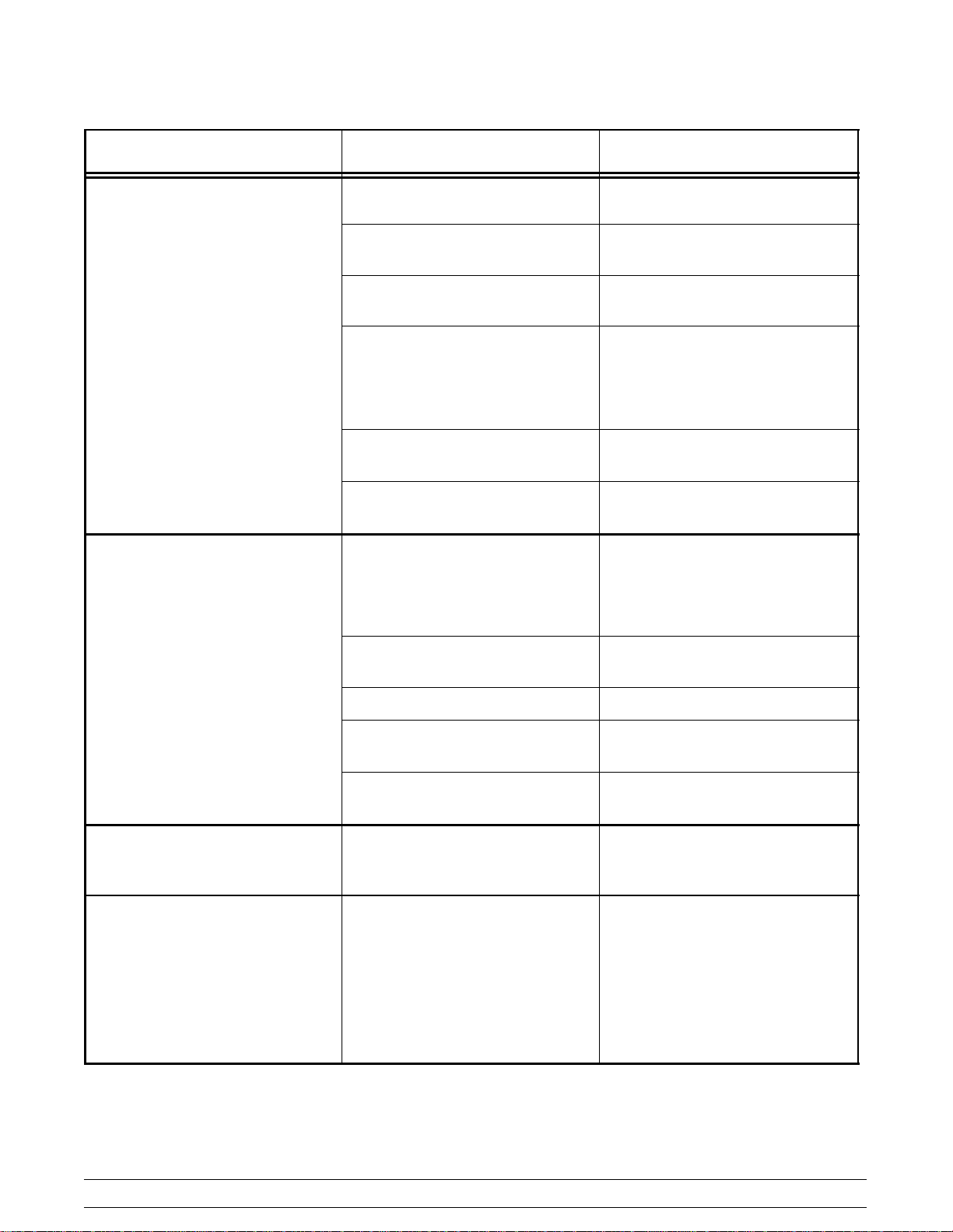
PROBLEM PROBABLE CAUSE REMEDY
12. The product is under-cooked
or overcooked.
13. The product is not cooking
evenly.
a. The release material sheet is
worn.
b. Incorrect cooking time. b. Reset the processor control for
c. Incorrect temperature. c. Adjust the processor control to
d. The upper platen or lower grill
surface is not clean and/or has
carbon build-up.
e. The preset gap height is
incorrect.
f. The heating zone is not
heating.
a. The upper platen or lower grill
surface is not clean and/or has
carbon build-up.
a. Replace the release material
sheet.
the correct time.
the proper setting.
d. Closing procedures must be
followed to properly clean the
upper platen and the lower grill
surface, and to remove carbon
build-up.
e. Call a service technician.
f. Call a service technician.
a. Closing procedures must be
followed to properly clean the
upper platen and the lower grill
surface, and to remove carbon
build-up.
14. The display reads “PROBE
OPEN”.
15. The display reads “HOME
SWITCH STUCK ON.”
b. Release material sheet is worn. b. Replace release material
sheet.
c. The platen is not level. c. Call a service technician.
d. The preset gap height is
incorrect.
e. Air pressure is not high
enough.
a. The thermocouple or the
thermocouple interface board
is faulty.
a. Defective motor control. a. Call a service technician.
b. Defective stepper motor. b. Call a service technician.
c. Defective stepper motor wire
harness.
d. Defective Home switch. d. Call a service technician.
d. Call a service technician.
e. Call a service technician.
a. Call a service technician.
c. Call a service technician.
30
Models C811 & C813Troubleshooting Guide
Page 35
PROBLEM PROBABLE CAUSE REMEDY
16. The display reads “HOME
SWITCH NOT SEEN.”
PROBLEM PROBABLE CAUSE REMEDY
1. The display reads “BLOWER
FAILURE”.
2. The burner will not light. The
display reads “IGNITION
FAILURE”.
a. Defective motor control. a. Call a service technician.
b. Defective stepper motor. b. Call a service technician.
c. Defective stepper motor wire
harness.
d. Defective Home switch. d. Call a service technician.
e. Broken platen cable. e. Call a service technician.
c. Call a service technician.
GAS ZONES ONLY
a. The blower is faulty. a. Call a service technician.
b. The pressure switch is faulty. b. Call a service technician.
a. The quick disconnect gas hose
is not fully engaged.
a. Re-engage the quick
disconnect.
3. The burner lights but will not
stay lit.
4. The burner lights but the zone
is cool or overheats.
b. The manual shutoff valve is in
the OFF position.
c. Air is in the gas hose. c. Wait 5 minutes before
d. The processor control is faulty. d. Call a service technician.
e. The spark ignition module is
faulty.
f. The gas solenoid is faulty. f. Call a service technician.
g. The electrode is faulty. g. Call a service technician.
h. The interface board is faulty. h. Call a service technician.
a. The electrode is faulty. a. Call a service technician.
b. Improper ground. b. Call a service technician.
a. The grill is out of calibration. a. Call a service technician.
b. The processor control is faulty. b. Call a service technician.
b. Turn the valve to the ON
position.
relighting.
e. Call a service technician.
c. The thermocouple is faulty. c. Call a service technician.
Models C811 & C813 Troubleshooting Guide
31
Page 36
Section 8 Parts List
REMARKS
WARR.
CLASS
QTY.
QTY.
PART
DESCRIPTION
C813
C811
NUMBER
+NUT-10-32 WHIZ FLANGE LOCKNUT 020983 9 8 000
+SCREW-SHOULDER 10-32X1/4X.125L 072849 6 8 103
+WASHER-3/8 USS FLAT CR3 000653 2 2 000
+SCREW-3/8-16X1 HEX HEAD CAP 079145 2 2 000
BACKSPLASH A. X72954 1 103
BACKSPLASH A. *C812* X73651 1 103
BAFFLE A.-COMBINATION *C845* C X73019 1 1 103
BAFFLE A.-COMBINATION *C845* L X73008 1 1 103
BAFFLE A.-COMBINATION *C845* R X73006 1 1 103
BAFFLE-INNER *C845* L 073022 2 2 103
BAFFLE-INNER *C845* R 073021 1 1 103
BAR A.-RELEASE MATERIAL X72843 3 2 103 PLATEN COVER
Parts List Models C811 & C813
BAR-BELLY *11/12/13/14/15* 075663-SP 1 1 103
BEARING 3/4 ID-SELF ALIGN 078730 6 4 103
32
BEARING-FLANGE 3/4 X 15/16 077042 12 8 000
BLOCK-CONTACT 1 NO 076013 6 6 103 CONTROL SWITCH
BLOCK-TERMINAL 1P 073423 3 3 103 UPPER CONTROL
BLOCK-TERMINAL 2P .25 SPD-24X 073033 1 1 103
BLOCK-TERMINAL 3P 20A, 300V 051331 4 4 103
BLOCK-TERMINAL 4P SCREW CER 052668 3 3 103 STEPPER MOTOR
BRACKET-CASTER-LOCK-C842 073322 4 4 103
BRACKET-PIVOT 076451 3 3 103
BULLNOSE A. X73023 1 1 103
BURNER-I.R. 073334 3 3 103
BUSHING-FLG .627IDX.12W OILITE 052394 6 6 103
BUSHING-SNAP 3/4ID X 1"OD BLK 053144 3 3 000
BUSHING-SNAP 5/8ID X 3/4OD-BLK 017462 1 1 000
BUSHING-SNAP 11/16 ID X 7/8OD 010548 6 6 103
BUSHING-SNAP 1-3/8ID X 1-3/4OD 027712 6 6 000
+GUARD-LENSE 075288 3 3 103
BUTTON-OPERATOR-BLACK 076012 3 3 000
BUTTON-OPERATOR-RED 076011 3 3 000
Page 37
WARR.
CLASS
QTY.
C813
QTY.
C811
PART
NUMBER
DESCRIPTION REMARKS
+GUARD-LENSE 075288 3 3 103
+SLIDE-GREASE CAN *C810* 073293 2 2 103
CAN-GREASE *C810* 073294 2 2 103
CARD-CHECKOUT GEN MKT INF GAP 073484 1 1 103
CARD-INSTALL-GAS GRILL 044218 1 1 000
Models C811 & C813
CASTER-5" 7-5/8 STEM 078377 2 2 103
CASTER-GRILL 5" SWIVEL W/LOCK 073240 2 2 103
+BRACKET-CASTER-LOCK-C842 073322 1 1 103
CLEVIS-ROD 1/2-20 THD 079777 3 2 103
COMPRESSOR-AIR-230V SERV 032129SER2 1 1 212
+ADAPTOR-HI TEMP 1/4X1/4 OD 058769-2 1 1 103
+FITTING-HI TEMP 1/4X1/4 OD 9 058771-2 1 1 103
+ MANIFOLD A.-*C842* 072695 1 103
+MANIFOLD A.-*C832* 073129 1 103
+SWITCH-PRESSURE 240V,3HP 077879-C 1 1 103
33
+TUBE-TEFLON .188IDX.250OD R403022 1 1 000
+TEE-1/4FPT X 1/4MPT X 1/4FPT 021277 1 1 103
+TEE-HI TEMP 1/4X1/4 OD 058770-2 1 1 103
+TANK-ACCUMULATOR 10LB-NPT 078820 1 1 103
+VALVE-CHECK 1/4MP 020959 1 1 103
CONTROL-GRILL TOUCH PAD *SEE - KIT A.-GRILL CONTROL-GEN MRKT
CONTROL-HI-LIMIT 450F RESET 070279 3 3 103
CONTROL-IGNITOR UTC *M35* X70301-02S 3 3 103
CONTROL-LIMIT W/SCREWS 078721 3 3 103 PLATEN
CONTROL-MOTOR *C810* GRILL 073279 3 3 212 CONTROL A.-LOWER*C811*
COVER A.-PLATEN *C810* W/RELEASE BAR X73256 3 2 103
CORD A.-POWER-250V-30A 4 WIRE 073668 1 1 103
COVER-FRONT *C845* 073009 1 1 103
CYLINDER-AIR 6IN STROKE C/C 079160 3 2 103
DEFLECTOR A.-FLUE *C811* X73510 1 1 103
DIAGRAM-WIRING *C811* 073475-23 1 000
DIAGRAM-WIRING *C813* 073725-23 1 000
Parts List
ELECTRODE 073409 3 3 103
Page 38
WARR.
CLASS
QTY.
C813
QTY.
C811
PART
NUMBER
DESCRIPTION REMARKS
+HOLDER-FUSE-15 A, 250 V 076299 1 1 103
E-RING 1/4 BLACK PHOS 032190 6 6 000
E-RING-3/4STEEL 077046 12 8 000
FAN-BLOWER 60CFM 120/230 VAC 079326-12 3 3 103
FASTENER-SNAP IN 1/4X15/16 078329 24 24 000
FILTER-CORCOM 6EH1 040140-001 3 3 103 TRANSFORMER
FITTING-1/4MPTX1/4OD TUBE 90DG 052560-2 6 6 103
FORM-QUALITY REPORT BY FAX 065712 1 1 000
FUSE-4 AMP BK/MDL-4-R 079837-040 1 1 000
GAUGE-130 PSI 1/8 MPT BACK MNT 072695-3 1 1 103 MANIFOLD A.-*C842*
GASKET-BRAIDED-HITEMP R70113 15' 15' 000
GASKET-CONTROL *C842* 072914 3 3 000
GASKET-FLUE *C845* 073419 2 2 000
GASKET-FRONT SHROUD 072983 1 1 000
GASKET-FRONT VIEW PORT *C845* 072985 3 3 000
GUIDE-PATTY PLACEMENT GEN MKT 073440 1 1 103
HANDLE-PLATEN 073250 3 2 103
HARNESS A.-COMP. VALVE *C842* X72743 1 1 103
HARNESS A.-COMP. VALVE X73145 1 103
HARNESS A.-IGNITOR *C845* X73146 3 3 103
HARNESS A.-MOTOR/PCB *M32/35*L X79603-L 3 2 103
HARNESS-12V-NEGATIVE-BOARD 073427 1 1 103
HARNESS-12V-POSITIVE-BOARD 073428 1 1 103
HARNESS-BLOWER 073608 3 3 103
HARNESS-COMPRESSOR *C845/C81 073422 1 1 103 CONTROL A.- UPPER
HARNESS-GAS VALVE 073426 1 1 103
HARNESS-GAS VALVE TREE 073437 1 1 103
HARNESS-HIGH LIMIT C845/C811 073471-L 1 1 103
HARNESS-HIGH LIMIT C845/C811 073471-M 1 1 103
HARNESS-HIGH LIMIT C845/C811 073471-R 1 1 103
HARNESS-IDC BOARD 073429-L 1 1 103
HARNESS-IDC BOARD 073429-M 1 1 103
Parts List Models C811 & C813
34
HARNESS-IDC BOARD 073429-R 1 1 103
Page 39
WARR.
CLASS
QTY.
C813
QTY.
C811
PART
NUMBER
DESCRIPTION REMARKS
HARNESS-IGNITOR-GROUND 073438 1 1 103
HARNESS-MC BOARD SUPPLY-24V 073460 1 1 103
HARNESS-PCB/GR SWITCH *C832* 072529 3 3 103
HARNESS-POWER SUPPLY-NEG 073436 1 1 103
HARNESS-PRESSURE SWITCH 073444 1 1 103
Models C811 & C813
HARNESS-SSR-LEFT*C845* 073095 1 1 103 CONTROL A.- UPPER
HARNESS-SSR-MIDDLE*C845 073096 1 1 103 CONTROL A.- UPPER
HARNESS-SSR-RIGHT*C845* 073097 1 1 103 CONTROL A.- UPPER
HARNESS-SWITCH 073425 1 1 103
HARNESS-TOUCH-CONTROL*C810-11* 073369 3 3 103
HARNESS-TRANSFORMER A.-115V 073454 1 1 103
HOSE ASSEMBLY-FLEXIBLE GAS 076390 1 1 103
HOSE-BEV.-.250IDX.438OD-100' R30317 5' 5' 000
KIT A.-3FT RESTRAIN CABLE 074948 1 1 103
KIT A.-ACCESSORY*INF GAP GEN X73459 1 000
35
CLIP-RELEASE MATERIAL-W/TAB 072673 6 000
RETAINER-SHEET RELEASE *C842* 072845 3 103
SCRAPER-TEFLON WIPER 075887 1 000
SCREW-10-32X3/8SLTD TRUSS 024298 9 000
SCREW-3/8-16X1 HEX HEAD CAP 001082 2 000
SHEET-RELEASE BOX(9) GEN MRK 073442 1 000
STRIP-REPLACEMENT 075888 1 000
WASHER-3/8 USS FLAT CR3 000653 2 000
KIT A.-ACCESSORY*INF GAP GEN X73678 1 000
CLIP-RELEASE MATERIAL-W/TAB 072673 4 000
RETAINER-SHEET RELEASE *C842* 072845 2 103
SCRAPER-TEFLON WIPER 075887 1 000
SCREW-10-32X3/8SLTD TRUSS 024298 9 000
SCREW-3/8-16X1 HEX HEAD CAP 001082 2 000
SHEET-RELEASE BOX(9) GEN MRK 073442 1 000
STRIP-REPLACEMENT 075888 1 000
WASHER-3/8 USS FLAT CR3 000653 2 000
Parts List
KIT A.-GRILL CONTROL-GEN MRKT X73474-SER 3 3 212
Page 40
WARR.
CLASS
QTY.
C813
QTY.
C811
PART
NUMBER
DESCRIPTION REMARKS
SOFTWARE-GRILL CONTROL GM 073474-109 3 3 103
+CONNECTOR-MATE LOCK-3 CIR-PIN 044823 3 3 103
Parts List Models C811 & C813
+GASKET-CONTROL *C842* 072914 3 3 000
KIT A.-GREASE SHIELD* X78330-SER 3 3 000
SHIELD-GREASE *M 22* 078285 6 4 000
FASTENER-SNAP IN 1/4X15/16 078329 24 24 000
LABEL-CONTROL COMPONENTS 073443 1 1 000
LABEL-ELEC-CAUTION 075484 1 1 000
LENS-MICA *C845* 072986 3 3 000
MANIFOLD A.-*C845* GAS X73109-02 1 1 103
ELBOW-3/8 MPT X 5/16 076370 3 3 103
FITTING-CROSS 3/8FPT-BLACK 078906 1 1 103
FITTING-REDUCER-1/2FPT-3/8FPT 077364 1 1 103
NIPPLE-3/8 MPT CLOSE BLK 076343 4 4 103
NIPPLE-3/8"X5-1/2 BLACK PIPE 073110 1 1 103
36
PLUG-3/8MPT-BLACK 078907 1 1 103
VALVE-GAS REDUNDANT 3-1/2 WC 079329-02 3 3 103 MANIFOLDA.-*C845*GAS
BLOCK-MANIFOLD .030 ORFICE 072695-7 1 103
FITTING-DIFFUSER1/4 MPT 072695-8 1 103
FITTING-HITEMP 1/4X1/4 OD 90 058771-2 1 103
FITTING-SWIVEL ELBOW 1/4 OD TB 072695-5 3 103
FITTING-SWIVEL ELBOW 1/4 OD TB 072695-6 1 103
GAUGE-130 PSI 1/8 MPT BACK MNT 072695-3 1 103
REGULATOR-PRESSURE 0-120 PSI 072695-2 1 103
BLOCK-MANIFOLD .030 ORFICE 072695-7 1 103
FITTING-DIFFUSER1/4 MPT 072695-8 1 103
FITTING-SWIVEL ELBOW 1/4 OD TB 072695-5 2 103
FITTING-SWIVEL ELBOW 1/4 OD TB 072695-6 1 103
GAUGE-130 PSI 1/8 MPT BACK MNT 072695-3 1 103
REGULATOR-PRESSURE 0-120 PSI 072695-2 1 103
MANIFOLD A.-*C842* 072695 1 103 COMPRESSOR A.-AIR
MANIFOLD A.-*C832* 073129 1 103
MOTOR-GEAR *M32/35* STEPPER V3 073247 3 2 103
Page 41
WARR.
CLASS
QTY.
C813
QTY.
C811
PART
NUMBER
DESCRIPTION REMARKS
+SCREW-SHOULDER 5/16 X 1 073249 6 4 103 GEAR MOTOR
+NUT-1/4-20 WHIZ FLANGE LOCK 017523 6 4 000
O-RING-1-3/16OD X .103W 052733-120 12 8 000
PANEL A.-BACK SERVICE *C811* X73513 1 1 103
PANEL A.-FRONT UPPER *C811* X73373 1 1 103 FRONT CONTROL
Models C811 & C813
PANEL A.-SIDE UPPER*832/835*LT X72962 1 1 103
PANEL A.-SIDE UPPER*832/835*RT X72965 1 1 103
PANEL-BACK-LOWER 073432 1 1 103
PANEL-FRONT-LOWER *C812* 073650 1 1 103
PANEL-SIDE-LOWER*C810* RIGHT 073261 1 1 103
PIN-SPRING UPPER *C842* 072542 6 4 000
PLATE A.-AIR SHUTTER SLIDE X79485 3 3 103
PLATE A .-DOOR HINGE-L X73569 1 1 103
PLATE A .-DOOR HINGE-R X73570 1 1 103
PLATE A.-GRILL *C845*GAS 072981 1 103
37
PLATE A.-GRILL *C813* 073724 1 103
PLATE-AIR SHUTTER BOTTOM 079576 3 3 103
PLATE-AIR SHUTTER SPACER *M35* 079482 3 3 103
PLATE-AIR SHUTTER TOP *C845* 073463 3 3 103
PLATE-HEAT TRANSFER 072982 9 9 103
PLUG-HOLE 1-3/4 DIA. 027132 3 3 000
PLUG-HOLE 1-3/8 DIA.-BLACK 053361 1 1 000
PLUG-HOLE 3/8 DIA BLACK PLASTI 050988 2 2 103
PLATEN A.-2600W 208V *C811* X73730-23 3 2 212
PULLEY-PLATEN CABLE 072662 6 6 103
PULLEY-PLATEN-LEFT 073248-L 3 3 103
+SCREW-1/4-20X3/8 SOCKET SET 039536 3 3 000
+SCREW-1/4-20X3/8 SOCKET SET 039536 3 3 000
PULLEY-PLATEN-RIGHT 073248-R 3 3 103
REGULATOR-PRESSURE 0-120 PSI 072695-2 1 1 103 MANIFOLD A.-*C842*
RELAY-4P-40A 200/240 COIL 050869-27 1 1 103 UPPER CONTROL
RELAY-SS 25A NON-ALARM 240 VAC 074210-02 6 6 103
Parts List
ROD-AIR SHUTTER ADJUST *C845* 073304 3 3 103
Page 42
WARR.
CLASS
QTY.
C813
QTY.
C811
PART
NUMBER
DESCRIPTION REMARKS
+FASTENER-SNAP IN 1/4X15/16 078329 24 24 000
SCREW-SHOULDER 4-40X.3755 SOC 058381 18 18 103
SCREW-SHOULDER 3/8X3-1/4 052010 12 8 103
SCREW-SHOULDER 10-32X1/4X.125L 072849 12 8 103
SEALANT-GORE-TEX 1/4 UNCOMP. R700033 000
SEAL-ARM *M32/35* 079952 6 4 000 ARM/BACKSPLASH
SHIELD A.-HEAT *C811/C845* X73597 3 3 103 OPERATOR BUTTONS
SHIELD-COUPLING FRONT 072926 3 3 103
SHIELD-COUPLING REAR 072927 6 4 103
SHIELD-GREASE *M 22* 078285 6 4 103
SHIELD-HEAT *C811* 073593 1 1 103 CONTROL A.-SWITCH
SHIELD-PLATE TUBE 072467 6 4 103
SHIELD-PLATE TUBE INNER 072467-1 6 4 103
SHROUD A.-PLATEN *C842* X72835 3 2 103
SHROUD-OUTER BACK *C845* LEFT 073004 1 1 103
SHROUD-OUTER BACK *C845* RIGHT 073003 1 1 103
SHIELD-GREASE *M 22* 078285 6 4 103
SPACER-HEAT TRANSFER PLATE 079074 54 54 000
Parts List Models C811 & C813
38
SPACER-SHROUD 076657 8 8 000
+PIN-SPRINGUPPER *C842* 072542 6 4 000
SPRING-EXTENSIONLATCH *C842* 072617 12 8 000 PLATEN SPRING
STANDOFF-NYLON 6-32 SNP/THREAD 040280-020 12 12 000
SUPPLY-POWER-10W 12VDC 073336 3 3 103
SWITCH-SCREW TERMINAL 075780 3 2 103 LATCH SWITCH
SWITCH-PRESSURE 074314 3 3 103 UPPER CONTROL
SWITCH-PRESSURE 240V,3HP 077879-C 1 1 103 COMPRESSOR A.-AIR
+ACTUATOR-HOME SWITCH 079792 3 2 103 STEPPER MOTOR
SWITCH-PUSHBUTTON-SPST 079442 3 2 103 GEAR ,PTPR
SWITCH-ROCKER-DPST-10AMPIP65 076989-WP 1 1 103
TANK-ACCUMULATOR 10LB-NPT 078820 1 1 103
TEE-1/4FPT X 1/4MPT X 1/4FPT 021277 1 1 103 AIR COMPRESSOR
TEE-HI TEMP 1/4X1/4 OD 058770-2 1 1 103 AIR COMPRESSOR
THERMOCOUPLE-K TYPE SS BRAID 079622 6 4 103
Page 43
WARR.
CLASS
QTY.
C813
QTY.
C811
PART
NUMBER
DESCRIPTION REMARKS
THERMOCOUPLE K 076222-K 6 6 103
TRANS.-100VA 120/208/240 PRI 079800 3 3 103
TRIM-CORNER *C810* LEFT 073263 1 1 103
TRIM-CORNER *C810* RIGHT 073264 1 1 103
TUBE-.170 ID X .250 OD 052561-40 2 2 000 R403021 TUBE-.170ID X .250OD
Models C811 & C813
TUBE A.-GAS BACK *C811* X73640 1 1 103
TUBE-NYLOBRADE 1/4ID X 7/16OD 020568-11 1 1 000 R30317 HOSE-BEV.-.250IDX.438OD-100'
TUBE-NYLOBRADE 1/4ID X 7/16OD 020568-18 1 1 000 R30317 HOSE-BEV.-.250IDX.438OD-100'
+CLAMP-HOSE 7/16-WIRE DICHROMAT 051742 3 3 000
TUBE-NYLOBRADE 1/4ID X 7/16OD 020568-19 1 1 000 R30317 HOSE-BEV.-.250IDX.438OD-100'
TUBE-TEFLON .188IDX.250OD R403022 10' 10' 000 AIR COMPRESSOR
VALVE-CHECK W/#69 ORIFICE M22 078332 3 2 103
VALVE-CHECK 1/4MP 020959 1 1 103 AIR COMPRESSOR
VALVE-GAS REDUNDANT 3-1/2 WC 079329-02 3 3 103 MANIFOLD A.-*C845* GAS
VALVE-PRESSURE RELIEF 70 PSI 072695-4 1 1 103 MANIFOLD
VALVE-SOLENOID 3 WAY 12 VDC 072695-1 3 2 103 MANIFOLD
VARISTOR A.-230VAC W/#10 SPADE X51733-C 2 2 103 AIR COMPRESSOR
39
WINDOW-FRONT VIEW PORT *C845* 073013 3 3 103
+LENS-MICA *C845* 072986 3 3 000
C81123N879 M C811 *CANADA*
CARD-INSTALL-C811 FRENCH- 073619FC 1 000
CARD-INSTALL-GAS GRILL-FR 044218-F 1 000
LABEL-ELEC-CAUTION-F/G 075484-FG 1 000
LABEL-FUSE REPLACEMENT 7A 074978 1 000
LABEL-INST-LIGHT*15E* 079567 1 000
LABEL-INST-LIGHT*15E*FREN 079567-F 1 000
LABEL-NOTICE-CASTERS 076389 1 000
LABEL-NOTICE-CASTERS-F/G 076389-FG 1 000
LABEL-WARN-GAS GRILL 078075 1 000
Parts List
LABEL-WARN-GAS GRILL-F/G 078075-FG 1 000
LABEL-WARN-GRILL-MCD-SVC- 072658-CAN 3 000
MAN-OPER C811 FRENCH (CAN 073625FCM 1 000
Page 44
WARR.
CLASS
QTY.
C813
QTY.
C811
PART
NUMBER
DESCRIPTION REMARKS
C81123N921 M C811 JIB
GAGE A.-GAP *C810-C811* JIB X73404 1 000
KIT A.-GRILL CONTROL-JIB X73274-SER 3 212
Parts List Models C811 & C813
40
Page 45
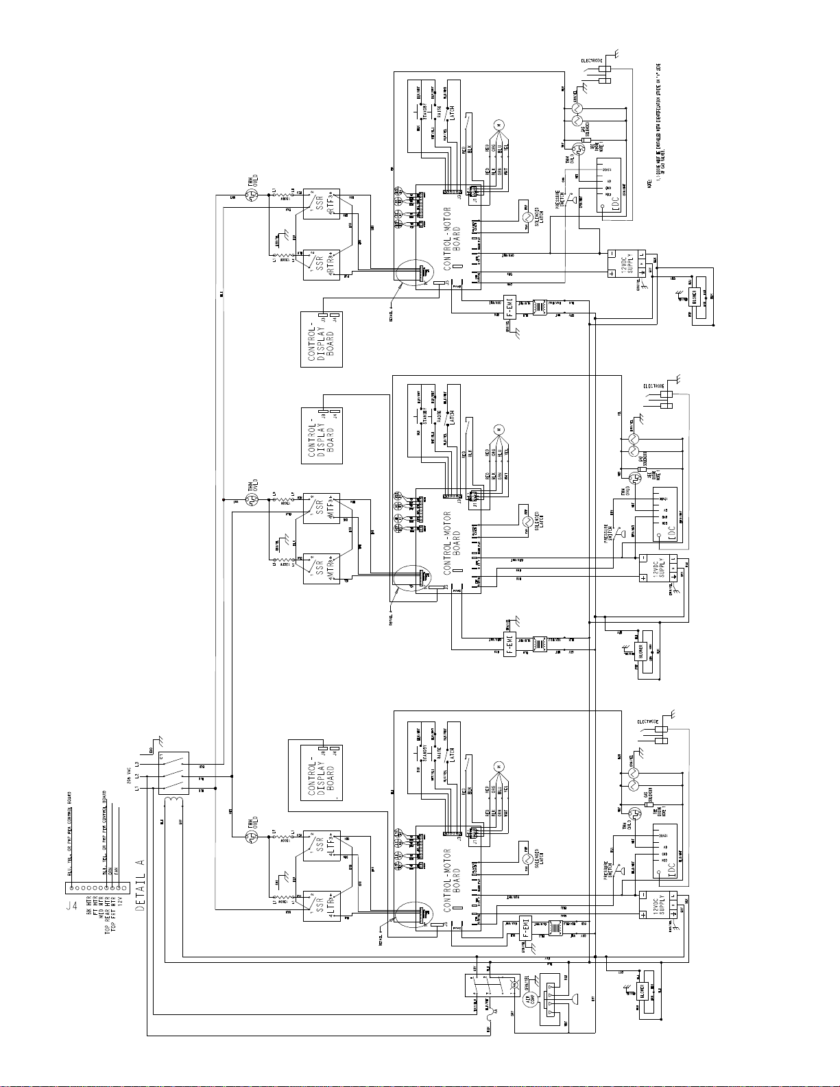
C811
073475-23
9/10
Page 46
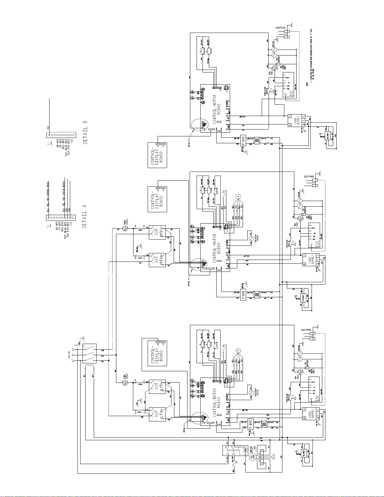
C813
073725-23
9/10
 Loading...