


Models C811 & C813
Auto Lift Grills
Operating Instructions
073625-M
9/15/10

Complete this page for quick reference when service is required:
Taylor Distributor:
Address:
Phone:
Service:
Parts:
Date of Installation:
Information found on data plate:
Model Number:
Serial Number:
Electrical Specs: Voltage Cycle
Phase
Maximum Fuse Size: Amps
Minimum Wire Ampacity: Amps
Part Number:
E September, 2010 Taylor
All rights reserved.
073625-M
The word Taylor and the Crown design
are registered trademarks in the United States
of America and certain other countries.
Taylor Company
750 N. Blackhawk Blvd.
Rockton, IL 61072

Table of Contents
Section 1 To th e Installer 1............................................
Installer Safety 1........................................................
Site Preparation 1.......................................................
Electrical Connections 1.................................................
Installation 2...........................................................
Section 2 To the Operator 3...........................................
Section 3 Safety 4....................................................
Section 4 Operator Parts Id entification 7...............................
C811 Exploded View 7..................................................
C813 Exploded View 8..................................................
Accessories 9..........................................................
Section 5 Important: To the Operator 10.................................
Models C811 & C813 Table of Contents

Table of Contents - Page 2
Section 6 Operating Procedures 11.....................................
Daily Opening Procedures 11..............................................
Operating Procedures 18.................................................
Daily Cleaning Procedures 20.............................................
Section 7 Troubleshooting Guide 28....................................
Section 8 Parts List 32.................................................
Wiring Diagrams 41......................................................
Note: Continuing research results in steady improvements; therefore,information
in this manual is subject to change without notice.
E September, 2010 Taylor
All rights reserved.
073625-M
The word Taylor and the Crown design
are registered trademarks in the United States
of America and certain other countries.
Table of Contents Models C811 & C813
Taylor Company
750 N. Blackhawk Blvd.
Rockton, IL 61072
Section 1 To the Installer
The following are general installation instructions.
For complete installation details, please see the
check out card.
cause severe injuries.
This unit has many sharp edges that can
Installer Safety
In all areas of the world, equipment should
be installed in accordance with existing local codes.
Please contact your local authorities if you have any
questions.
Care should be taken to ensure that all basic safety
practices are followed during the installation and
servicing activities related to the installation and
service of Taylor equipment.
S Only Taylor authorized service personnel
should perform installation and repairs on
the equipment.
S Authorized service personnel should consult
OSHA Standard 29CFRI910.147 or the
applicable code of the local area for the
industry standards on lockout/tagout
procedures before beginning any installation
or repairs.
S Authorized service personnel must ensure
that the proper PPE is available and worn
when required during installation and
service.
S Authorized service personnel must remove
all metal jewelry, rings, and watches before
working on electrical equipment.
The main power supply(s) to the equipment
must be disconnected prior to performing any
repairs. Failure to follow this instruction may result in
personal injury or death from electrical shock or
hazardous moving parts as well as poor
performance or damage to the equipment.
Site Preparation
Review the area where the unit will be installed
before uncrating the unit. Make sure all possible
hazards to the user or equipment have been
addressed.
Electrical Connections
The grill is supplied with one power cord. Check the
data plate on the grill for voltage, cycle, phase and
electrical specifications.
For proper power connections, refer to the wiring
diagram provided inside the left side panel, attached
to the gas manifold assembly. The power connection
is located behind the access line cover on the front
of the grill.
In the United States, this equipment is intended to
be installed in accordance with the National
Electrical Code (NEC), ANSI/NFPA 70-1987. The
purpose of the NEC code is the practical
safeguarding of persons and property from hazards
arising from the use of electricity. This code contains
provisions considered necessary for safety.
Compliance therewith and proper maintenance will
result in an installation essentially free from hazard!
In all other areas of the world, equipment should be
installed in accordance with the existing local codes.
Please contact your local authorities.
The Proper Wire Size and Branch Circuit
Overcurrent Device shall be selected according to
the data label information and in accordance with
CEC Part I 2006, Section 14-100(e)(i).
Note:Allrepairsmustbeperformedbyan
authorized Taylor Service Technician.
Models C811 & C813 To the Installer
1
FOLLOW YOUR LOCAL ELECTRICAL CODES!
CAUTION: THIS EQUIPMENT MUST BE
PROPERLY GROUNDED! FAILURE TO DO SO
CAN RESULT IN SEVERE PERSONAL INJURY
FROM ELECTRICAL SHOCK!
This unit is provided with an equipotential
grounding lug that is to be properly attached to the
rear of the frame by the authorized installer. The
installation location is marked by the equipotential
bonding symbol (5021 of IEC 60417-1) on both the
removable panel and the equipments frame.
S Stationary appliances which are not
equipped with a power cord and a plug or
another device to disconnect the appliance
from the power source must have an all-pole
disconnecting device with a contact gap of
at least 3mm installed in the external
installation.
S Appliances that are permanently connected
to fixed wiring and for which leakage
currents may exceed 10 mA, particularly
when disconnected or not used for long
periods, or during initial installation, shall
have protective devices such as a GFI, to
protect against the leakage of current,
installed by the authorized personnel to the
local codes.
S Supply cords used with this unit shall be
oil-resistant, sheathed flexible cable not
lighter than ordinary polychloroprene or
other equivalent synthetic
elastomer-sheathed cord (Code designation
60245 IEC 57) installed with the proper cord
anchorage to relieve conductors from strain,
including twisting, at the terminals and
protect the insulation of the conductors from
abrasion.
Installation
WARNING: Improper installation, adjustment,
alteration, service or maintenance can cause
property damage, injury or death. Read the
installation, operating and maintenance
instructions thoroughly before installing or
servicing this equipment.
This machine is designed for indoor use only.
DO NOT installthemachineinanarea
where a water jet could be used to clean or rinse the
machine. Failure to follow this instruction may result
in serious electrical shock.
This grill must be installed on a level
surface. Failure to comply may result in personal
injury or equipment damage.
Installation of Cab le Kit
If the unit is permanently connected, the Cable Kit
must be installed. Flexible conduit must be used
when installing the appliance.
Ventilation and Clearance
To ensure proper operation of this appliance, it must
be installed so that the products of combustion are
efficiently removed.
After set up, do not store anything on top of
the grill. Failure to follow this instruction may result
in a fire hazard.
Grease Disposal Container
If the grill is not factory-equipped with grease
disposal containers, the store is required to provide
appropriate grease disposal containers in
accordance with NSF Standard 4 requirements.
2
Models C811 & C813To the Installer

Section 2 To the Operator
The grill you have purchased has been carefully
engineered and manufactured to provide
dependable operation.
This grill, when properly operated and maintained,
will produce a consistent quality product. Like all
mechanical products, they require cleaning and
maintenance. A minimum amount of care and
attention is necessary if the operating procedures in
this manual are followed closely.
This Operator's Manual should be read before
operating or performing any maintenance on your
equipment.
It is strongly recommended that all personnel
responsible for the equipment's operation and
cleaning, review these procedures for proper training
and assurance that no misunderstandings exist.
In the event you should require technical assistance,
please contact your local authorized Taylor
Distributor.
Note: Warranty is valid only if the parts are
authorized Taylor parts, purchased from an
authorized Taylor Distributor, and the required
service work is provided by an authorized Taylor
service technician. Taylor reserves the right to deny
warranty claims on equipment or parts if
non-approved parts or refrigerant were installed in
the machine, system modifications were performed
beyond factory recommendations, or it is determined
that the failure was caused by neglect or abuse.
Note: Constant research results in steady
improvements; therefore, information in this
manual is subject to change without notice.
If the crossed out wheeled bin symbol is
affixed to this product, it signifies that this product is
compliant with the EU Directive as well as other
similar legislation in effect after August 13, 2005.
Therefore, it must be collected separately after its
use is completed, and cannot be disposed as
unsorted municipal waste.
The user is responsible for returning the product to
the appropriate collection facility, as specified by
your local code.
For additional information regarding applicable local
laws, please contact the municipal facility and/or
local distributor.
Models C811 & C813 To the Operator
3
Section 3 Safety
We, at Taylor Company, are concerned about the
safety of the operator when he or she comes in
contact with the grill and its parts. Taylor has gone
to extreme efforts to design and manufacture built-in
safety features to protect both you and the service
technician. As an example, warning labels have
been attached to the grill to further point out safety
precautions to the operator.
IMPORTANT - Failure to adhere to the
following safety precautions may result in
severe personal injury or death. Failure to
comply with these warnings may damage the
machine and its components. Component
damage will result in part replacement expense
and service repair expense.
To Operate Safely:
DO NOT operate the grill without reading
this operator's manual. This manual should be kept
in a safe place for future reference.
S Appliances that are permanently connected
to fixed wiring and for which leakage
currents may exceed 10 mA, particularly
when disconnected or not used for long
periods, or during initial installation, shall
have protective devices such as a GFI, to
protect against the leakage of current,
installed by the authorized personnel to the
local codes.
S Supply cords used with this unit shall be
oil-resistant, sheathed flexible cable not
lighter than ordinary polychloroprene or
other equivalent synthetic
elastomer-sheathed cord, (Code designation
60245 IEC 57), installed with the proper
cord anchorage to relieve conductors from
strain, including twisting, at the terminals
and protect the insulation of the conductors
from abrasion.
IMPORTANT: DO NOT use a water jet or
spray excessive water on or anywhere near the
grill. Failure to follow this instruction may result in
serious electrical shock and cause permanent
electrical and mechanical damage to internal parts.
Failure to follow the instructions below may
result in severe injury or death from electrocution:
S DO NOT operate the grill unless it is
properly grounded.
S DO NOT operate the grill with larger fuses
than specified on data label.
S DO NOT operate the grill unless all service
panels and access doors are attached with
screws.
S Stationary appliances which are not
equipped with a power cord and a plug or
other device to disconnect the appliance
from the power source must have an all-pole
disconnecting device with a contact gap of
at least 3 mm installed in the external
installation.
Failure to follow this instruction may result in:
S serious electrical shock
S burns from hot steam
S liquid collecting inside the grill and
destroying electrical components
4
Models C811 & C813Safety
This appliance must be isolated from all
combustible construction and materials including,
but not limited to; walls, partitions, furniture, floors,
curtains, paper, boxes, and decorations. Failure to
comply may result in fire and cause destruction and
severe injury.
FORYOURSAFETY
Do not store or use gasoline or other
flammable vapors or liquids in the vicinity of
this or any other appliance.
USE EXTREME CAUTION while setting up,
operating, and cleaning the grill.
S Avoid coming in contact with hot grill
surfaces or with hot grease.
S DO NOT prepare or remove product without
proper equipment.
S DO NOT allow untrained personnel to
operate this grill.
Failure to follow these instructions can result in burn
injuries.
Take caution to protect eyes, lungs, and all
parts of the body from potential harm when using
any chemical cleaner. Failure to follow this
instruction may result in a chemical burn.
DO NOT use any abrasives or cleaners
other than approved food service cleaners and
degreasers. Failure to comply may cause illness to
the consumer and may also damage grill surfaces.
For thorough cleaning, the grill must be
pulled away from the wall. Before moving the grill,
remove the grease cans. Turn off the gas at the
quick connect shut-off valve on the flexible hose.
Disconnect the gas quick connector. Disconnect the
tether to the grill, located on the back panel of the
unit.
To return the grill to its original position, reverse the
steps. Use extreme caution to smoothly and slowly
roll the grill backward into place.
Failure to do so may cause the grill to tip and can
result in severe equipment damage or personal
injury.
DO NOT use cold water or ice to cool the
upper platen or the lower cook surface. Failure to
follow this instruction may result in:
S serious electrical shock
S burns from hot steam
S liquid collecting inside the grill and
destroying electrical components
S DO NOT obstruct the ventilation openings at
the rear of this appliance.
S DO NOT obstruct the flow of air in and
around the grill.
NOTICE all warning labels that have been
attached to the grill to further point out safety
precautions to the operator.
Models C811 & C813 Safety
5

This piece of equipment is made in America and has
American sizes on hardware. All metric conversions
are approximate and vary in size.
NOISE LEVEL: Airborne noise emission does not
exceed 70 dB(A) when measured at a distance of
1.0 meter from the surface of the machine and at a
height of 1.6 meters from the floor.
If the crossed out wheeled bin symbol is
affixed to this product, it signifies that this product is
compliant with the EU Directive as well as other
similar legislation in effect after August 13, 2005.
Therefore, it must be collected separately after its
use is completed, and cannot be disposed as
unsorted municipal waste.
These instructions are valid only if the country code
symbol appears on the appliance. If the symbol does
not appear on the appliance, refer to the technical
instructions which give the necessary instructions for
adapting the appliance to the utilization conditions of
that country.
The user is responsible for returning the product to
the appropriate collection facility, as specified by
your local code.
For additional information regarding applicable local
laws, please contact the municipal facility and/or
local distributor.
6
Models C811 & C813Safety
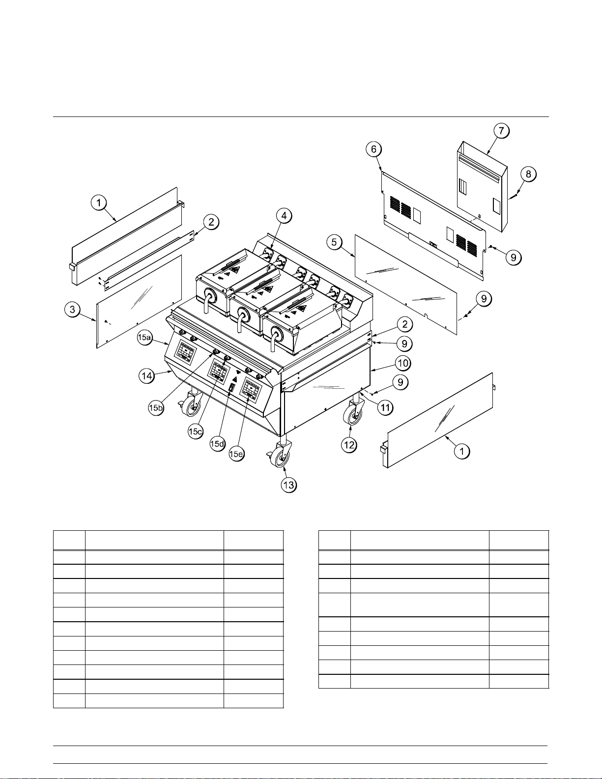
Section 4 Operator Parts Identification
C811 Exploded View
Figure 1
ITEM DESCRIPTION PART NO.
1 CAN-GREASE 073294
2 SLIDE-GREASE CAN 073293
3 PANEL-SIDE-LOWER*LEFT 073262
*4 KIT A.-GREASE SHIELD X78330-SER
5 PANEL-BACK LOWER 073432
6 PANEL A.-BACK SERVICE X73513
7 DEFLECTOR A.-FLUE X73510
8 SCREW-3/8-16X34SERR HWH 017328
9 SCREW-10-32X3/8SLTD TRUS 024298
10 PANEL-SIDE-LOWER*RIGHT 073261
11 NUT-JAM 1-1/2-12 (2 PCS) 073594
Models C811 & C813 Operator Parts Identification
ITEM DESCRIPTION PART NO.
12 CASTER-5" 7-5/8 STEM 078377
13 CASTER-GRILL 5” SWIVELLOC 073240
14 PANEL-FRONT-LOWER 073650
15 CONTROL A.-SWITCH
(INCLUDES 15a-15e)
15a PANELA.-FRONT UPPER X73373
15b BUTTON-OPERATOR-RED 076011
15c BUTTON-OPERATOR-BLACK 076012
15d SWITCH-ROCKER-DPST-10A 076989-WP
15e CONTROL-GRILL TOUCH PAD 073474
*NOTE: 1 KIT PER PLATEN
7
---
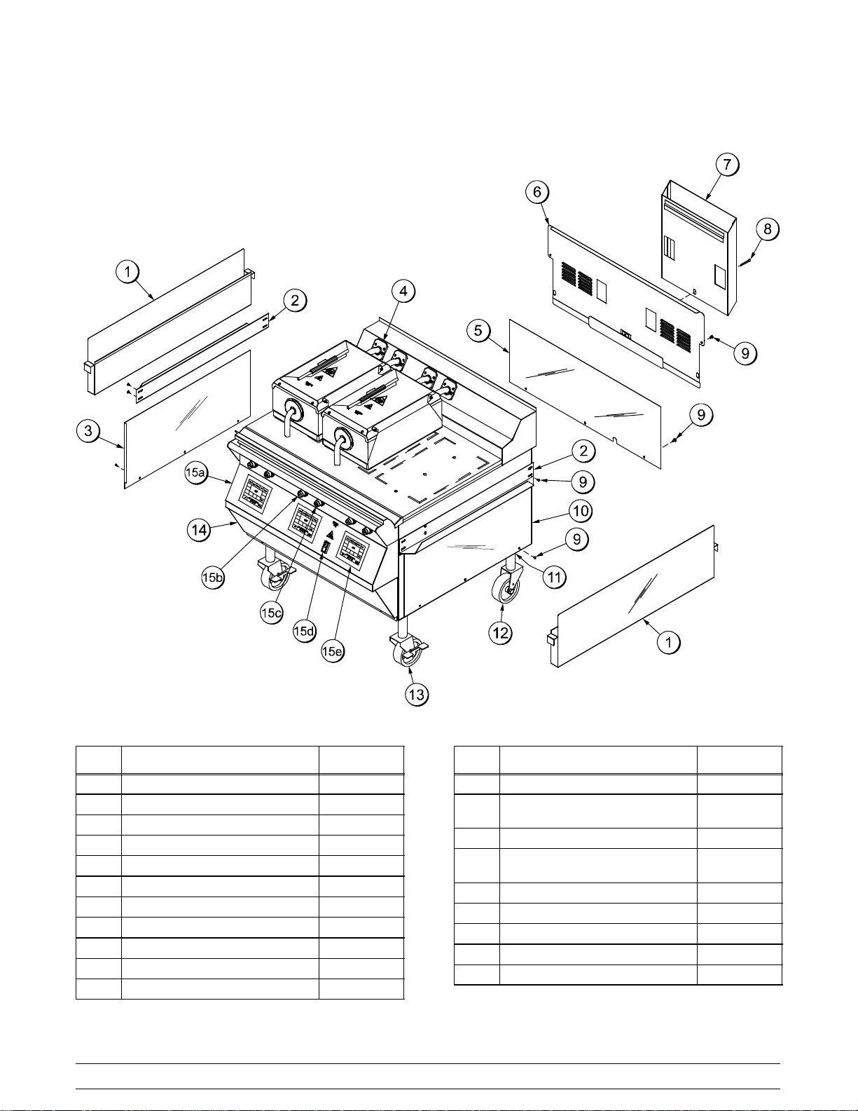
C813 Exploded View
ITEM DESCRIPTION PART NO.
1 CAN-GREASE 073294
2 SLIDE-GREASE CAN 073293
3 PANEL-SIDE-LOWER-LEFT 073262
*4 KIT A.-GREASE SHIELD X78330-SER
5 PANEL-BACK-LOWER 073432
6 PANEL A.-BACK SERVICE X73513
7 DEFLECTOR A.-FLUE X73510
8 SCREW-3/8-16X3/4 SERRATED 017328
9 SCREW-10-32X3/8SLTD TRUS 024298
10 PANEL-SIDE-LOWER-RIGHT 073261
11 NUT-JAM 1 1/2-12 STEEL 073594
Figure 2
8
ITEM DESCRIPTION PART NO.
12 CASTER-5" 7-5/8 STEM 078377
13 CASTER-GRILL 5" SWIVEL
W/LOCK
14 PANEL-FRONT-LOWER 073650
15 CONTROL A.-SWITCH
(INCLUDES ITEMS 15a-15e)
15a PANELA.-FRONT UPPER X73373
15b BUTTON-OPERATOR-RED 076011
15c BUTTON-OPERATOR-BLACK 076012
15d SWITCH-ROCKER-DPST-10A 076989-WP
15e CONTROL-GRILL-TOUCH PAD 073474
*NOTE: 1 KIT PER PLATEN
073240
X73525
Models C811 & C813Operator Parts Identification
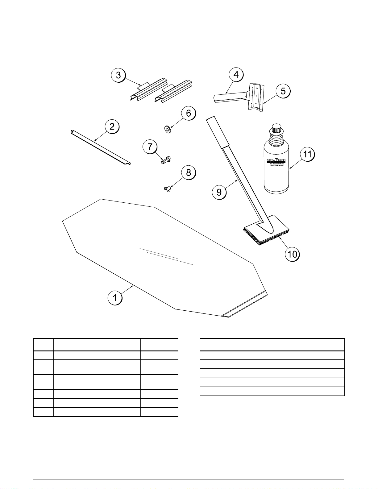
Accessories
Figure 3
ITEM DESCRIPTION PART NO.
1 SHEET-RELEASE (BOX 9) 073442
*2 RETAINER-SHEET RELEASE
(RETENTION BAR)
**3 CLIP-RELEASE MATERIAL
W/TAB
4 SCRAPER-TEFLON WIPER 075887
5 STRIP-REPLACEMENT 075888
6 WASHER-3/8 USS FLAT 000653
072845
072673
Models C811 & C813 Operator Parts Identification
ITEM DESCRIPTION PART NO.
7 SCREW-3/8-16X 1 HEX HEAD 001082
8 SCREW-10-32 X 3/8 SLTD 024298
9 HOLDER-CLEANING 073736
10 PAD-CLEANING 073737
11 CLEANER-STERA SHEEN 6 QT 073160-SAM
* SHOWN PER PLATEN
** SHOWN PER PLATEN
(NOTE: EXTRA CLIPS ARE SENT WITH GRILL)
101007
9
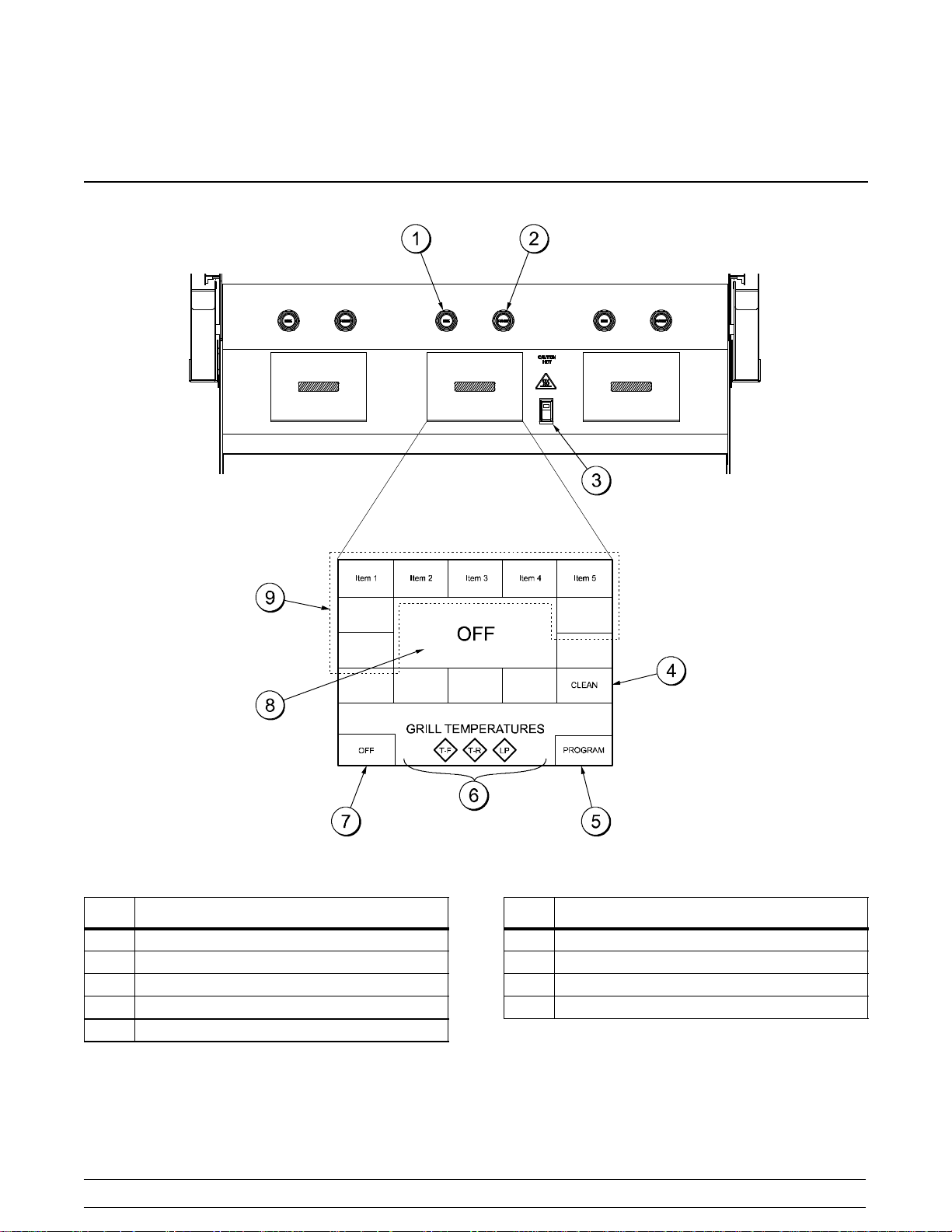
Section 5 Important: To the Operator
ITEM DESCRIPTION
1 RAISE BUTTON
2 STANDBY/COOK MODE BUTTON
3 POWER SWITCH
4 CLEAN MODE KEY
5 PROGRAM KEY
Figure 4
10
ITEM DESCRIPTION
6 TEMPERATURE INDICATOR LIGHTS
7 POWER KEY
8 FUNCTION DISPLAY
9 MENU SELECT KEYS
Models C811 & C813Important: To the Operator
 Loading...