

Page 1
®
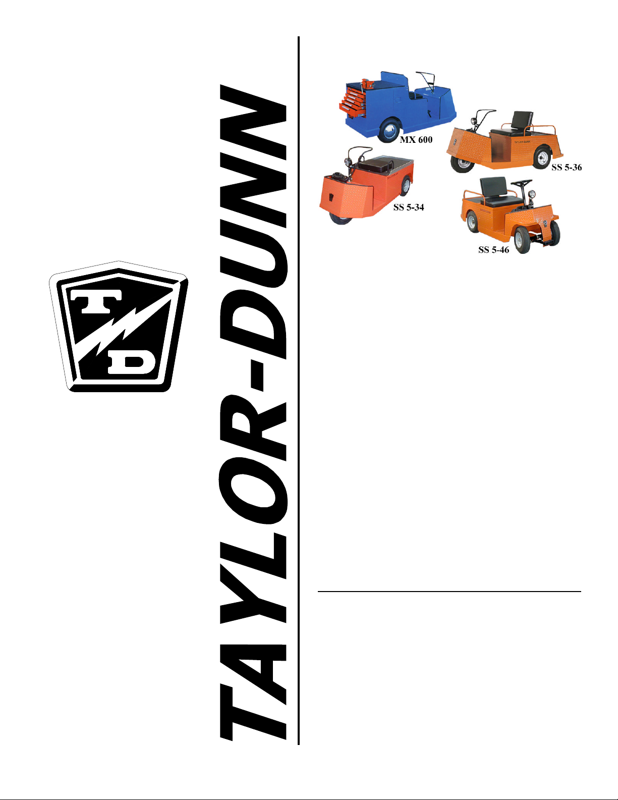
Models:
SS5-34 serial number starting 94506
SS5-36 serial number starting 90400
SS5-46 serial number starting 161403
MX6-00 serial number starting 113227
The Best Way
To Go
About Your
Business
MANUAL MS-534-08
Operation, Troubleshooting
Manual
Revision: F
Page 2

Page 3
Operator and Maintenance
Manual
A guide to the operation and maintenance of Taylor-Dunn
Vehicles
®
Page 4

COPYRIGHT NOTICE
Copyright © 2001 by Taylor-Dunn® Mfg. All rights reserved.
No part of this work may be reproduced or transmitted in any form or by any means, electronic
or mechanical, including photocopying and recording, or any information storage or retrieval
system without prior written permission of Taylor-Dunn® Mfg. unless such copying is
expressly permitted by federal copyright law. Address inquiries to Reference Permissions,
Taylor-Dunn® Mfg., 2114 W. Ball Road, Anaheim, CA 92804
TAYLOR-DUNN SERVICE CENTER
For more information about this and other Taylor-Dunn® manuals, please write Taylor-Dunn®:
Taylor-Dunn® Mfg.
2114 W. Ball Road
Anaheim, CA 92804
(Attn: Technical Writer)
Page 5

Table of Contents
Introduction .......................................................................................... 1
Who Should Read This Manual .................................................... 2
Responsibilities.............................................................................. 2
How To Use This Manual ............................................................ 3
Conventions ................................................................................... 4
Vehicle Description and Specifications .................................... 1-1
Vehicle Description ..........................................................................1-2
Standard Specifications ..............................................................1-3
Taking Delivery of Your Vehicle ................................................1-4
What To Do If You Find a Problem ...........................................1-4
Safety Rules and Operational Information .............................. 2-1
Safety Rules and Guidelines ..........................................................2-2
Responsibilities...........................................................................2-2
Safety Rules ...............................................................2-3
Driver Training Program Guidelines ..........................................2-4
Driver Qualifications ..................................................................2-4
Who is Qualified to Drive? ........................................2-4
Minimum Requirements ............................................2-4
Vehicle Controls ...............................................................................2-5
Guidlines for Vehicle Operation ...................................................2-7
Driving.........................................................................................2-7
Loading and Unloading ...............................................................2-7
Parking.........................................................................................2-7
Towing.........................................................................................2-8
Maintenance and Service Procedures ..................................... 3-1
Maintenance Guidelines .............................................................3-2
Maintenance Guidelines for Vehicles
Used in Severe Conditions .................................................3-3
Periodic Maintenance Table ...........................................................3-4
Lubrication ........................................................................................... 3-5
Trouble shooting Guide .........................................................................3-6
Brakes.................................................................................................3-9
Adjusting the Brake Band ....................................................... 3-10
SS5-34 Brake System .............................................................. 3-10
Adjusting the Brake Cable ...................................... 3-11
Removing the Brake Assembly .............................. 3-12
SS5-36, SS5-46 and MX-600 Brake System ......................... 3-13
Adjusting the Brake Pedal Linkage ........................ 3-13
Inspecting and Replacing the Park Brake Lock (All Models) 3-14
Replacement and Wear
of Park Brake Lock (All Models) .................. 3-15
SS5-36, SS5-46 and MX-600 Rear Brakes............................. 3-16
Replacing the Brake Drum...................................... 3-17
Replacing the Brake Shoes...................................... 3-18
i-i
Page 6

INTRODUCTION
Front Fork and Steering ............................................................... 3-20
Rear Axle and Drive Assembly .................................................... 3-30
Motor................................................................................................ 3-47
Battery ............................................................................................. 3-51
Front Fork ................................................................................ 3-21
Removing the Front Fork ....................................... 3-22
Removing the Front Springs ................................... 3-23
Removing the Front Axle ........................................ 3-23
Replacing the Front Wheel Bearings ...................... 3-24
Replacing and Adjusting the
Front Fork Collar Bearing .............................. 3-24
Optional Geared Steering ........................................................ 3-25
SS5-34 Geared Steering Assembly ......................... 3-25
SS5-36, SS5-46 and MX-600 Geared
Steering Assembly .......................................... 3-27
SS5-46 Front Axle and Steering............................................... 3-28
Replacing the Front Wheel Bearings ...................... 3-28
Removing the Front Axle Assembly ...................... 3-29
Aligning the Front Wheels ...................................... 3-29
Replace the King Pin or Bushings .......................... 3-29
Removing the SS5-34 Rear End Assembly............................. 3-31
Removing the SS5-36and SS5-46 Rear End Assembly .......... 3-32
Removing the MX-600 Rear End Assembly ......................... 3-33
Differential and Rear Axle ....................................................... 3-34
SS5-34 Drive Service............................................... 3-35
Disassembly of the
Belt Drive Assembly ...................... 3-35
Removing and Servicing the Rear Axle .. 3-36
Differential Service and Repair .............. 3-37
Motor Removal ...................................... 3-40
Changing the Differential Oil ................. 3-40
Adjusting Belt Tension .......................... 3-41
Aligning Pulleys ...................................... 3-42
SS5-36, SS5-46 and MX-600 Drive Service .......... 3-43
SS5-36/SS5-46/MX-600 Removing and
Servicing the Rear Axle .................. 3-43
Servicing the Differential ........................ 3-44
SS5-36/SS5-46/MX-600 Motor Removal .............................. 3-47
SS5-34 Motor Removal ........................................................... 3-48
Brushes..................................................................................... 3-48
Installing New Brushes ........................................... 3-49
Motor Disassembly ................................................................. 3-49
Inspecting the Armature .......................................................... 3-50
Cleaning .................................................................................... 3-51
Servicing the Batteries ............................................................. 3-52
Charging .................................................................................... 3-52
Battery Storage ........................................................................ 3-52
Battery Configuration .............................................................. 3-53
i-iv
Page 7

SECTION 4-Electrical Troubleshooting ..................................... 1
Test Equipment Required: ................................................................. 3
IMPORTANT NOTES and INSTRUCTIONS ............................... 3
Definitions: .......................................................................................... 4
Section 4a-Vehicle Wire Diagrams ............................................. 1
Model MX 6-00 ..................................................................................... 2
Model SS 5-34, SS5-46 and SS 5-36 with the
Dual Chassis Harness ................................................................ 3
Model SS 5-34 with the Single Chassis Harness .......................... 4
Section 4-Special Troubleshooting Guide ................................... 1
PMC CONTROL ................................................................................. 2
PLUGGING DIODE............................................................................. 4
FREEWHEEL DIODE .......................................................................... 5
ISO......................................................................................................... 6
SOLENOIDS........................................................................................ 8
MOTOR .............................................................................................. 11
SECTION 4b-Lestronic II ChargerTroubleshooting .................. 1
Operating Instructions and Theory of Operation.....................2
Testing the Charging Cycle ................................................................. 3
Test Equipment Required for Troubleshooting ................................ 4
Important Notes and Instructions ........................................................4
Troubleshooting for Built-in Charger ................................................5
Troubleshooting for Portable Charger ...............................................8
Testing The Timer Relay ...................................................................... 9
Testing the Interlock Relay ..................................................................10
SECTION 4c-Signet ChargerTroubleshooting............................ 1
Operating Instructions and Theory of Operation.....................2
Testing the Charging Cycle ....................................................3
Test Equipment Required for Troubleshooting......................... 4
Status LED Error Code ...........................................................5
Troubleshooting......................................................................6
i-iii
Page 8

TABLE OF CONTENTS
Illustrated Parts List ................................................................ 5-1
IDENTIFYING YOUR VEHICLE ...................................................5-2
BRAKE PEDAL LINKAGE AND ACCELERATOR PEDAL (SS5-34) .... 5-4
BRAKE PEDAL LINKAGE (SS5-36, SS5-46 AND MX-600) ........... 5-6
FRONT AXLE, WHEEL AND SUSPENSION ................................... 5-8
FRONT AXLE, WHEEL AND STEERING (SS5-46) ....................... 5-10
TILLER STEERING .................................................................. 5-12
GEARED STEERING (SS5-34) .................................................. 5-14
GEARED STEERING (SS5-36, SS5-46 AND MX-600) ................ 5-16
INSTRUMENT PANEL (SS5-34, SS5-46 AND SS5-36)............... 5-18
CONTROLS AND INSTRUMENTS (MX-600) ............................. 5-20
MOTOR SS5-34 .................................................................... 5-22
MOTOR SS5-36, SS5-46 & MX-600 ...................................... 5-24
REAR AXLE (SS5-34) ............................................................. 5-26
REAR AXLE (SS5-36, SS5-46 AND MX-600) ............................ 5-28
DIFFERENTIAL (SS5-34) ......................................................... 5-30
DIFFERENTIAL (SS5-36, SS5-46 AND MX-600) ....................... 5-32
SS5-36, SS5-46 DIFFERENTIAL FRAME ................................... 5-34
DECK AND VISE ASSY (MX-600) ............................................ 5-36
TOOLBOX ASSY (MX-600) ..................................................... 5-38
BATTERY .............................................................................. 5-40
BRAKE ASSY (SS5-34) ........................................................... 5-42
REAR BRAKE (SS5-36, SS5-46 AND MX-600) ......................... 5-44
PMC CONTROL PANEL ......................................................... 5-46
BATTERY CHARGER .............................................................. 5-48
REAR TIRE AND WHEEL ......................................................... 5-50
SEAT CUSHIONS ................................................................... 5-52
DECALS................................................................................ 5-54
MIRRORS OPTION ................................................................. 5-56
STROBE AND STOP LIGHT OPTION ....................................... 5-58
HEADLIGHT .......................................................................... 5-60
PARTS APENDIX A................................................................. 5-63
SIGNET CHARGER ................................................................. 5-64
i-iv
Page 9

Introduction
Your purchase...
What’s contained
in this manual?
Before servicing....
The purchase of this vehicle shows a belief in high quality products
manufactured in the USA. Taylor-Dunn®, a leading manufacture of
electric burden and personnel carriers since 1949, wants to be sure
that you get the most out of your vehicle and that it provides years
of reliable service. Please continue to read this manual and enjoy
your high quality Taylor-Dunn® vehicle.
This manual is to serve as a guide for the service, repair and
operation of the Taylor-Dunn® vehicle, and is not intended as a
training guide. Taylor-Dunn® has made every effort to include as
much information as possible about the operation and maintenance
of it’s vehicles.
Included in this manual are the:
n Vehicle Description
n Safety Rules and Guidelines
n Operational Information
n Operator Responsibilities
n Owner Responsibilities
n Control Operation and Location Information
n Maintenance and Troubleshooting Information
n Parts Lists of Standard Parts
Before servicing, operating, training, or performing maintenance
on this or any Taylor-Dunn® vehicle, read the entire manual and
note all cautions, warnings, and notes contained in this manual.
1
Page 10

INTRODUCTION
Who Should Read This Manual
This manual is intended for use by anyone who is going to operate, own, perform maintenance, service, or
order parts for a Taylor-Dunn® vehicle. Each person should be familiar with the parts of this manual that
apply to them.
Responsibilities
Of the Owner...
The owner of this or any Taylor-Dunn® vehicle is responsible for the training of
operators, overall maintenance, and repairs of the vehicle. Owners should keep
a record of conducted training and services or repairs performed on the vehicle.
(OSHA Regulation, 29 CFR (Code of Federal Regulations) 1910.178 Powered
Industrial Truck Operator Training.)
Of the Operator...
The operator is responsible for the safe operation of the vehicle, preoperational
and operational checks on the vehicle, and reporting any problems to service
and repair personnel.
Of the Service Personnel...
The service personnel are responsible for the service and maintenance of the
vehicle, from lubrication to repair of damaged or worn parts. At no time should
a service person allow any untrained personnel to service or repair this or any
vehicle. For the purposes of training, a qualified service person may oversee
the repairs or services being made to a vehicle by an individual in training. At
no time should an untrained individual be allowed to service or repair a vehicle
without supervision. This manual is not a training guide.
2
Page 11

How To Use This Manual
This manual is organized into four main sections:
n Section 1: “Safety Rules and Operational Information,” outlines the safety issues and
operational issues of the vehicle. Including the location and operation of controls, the
operational checks that are to be performed, and various subjects that should be included
in any operator and service training programs implemented by the owner.
n Section 2: “Maintenance and Repair,” gives specific information on the maintenance
and repair of the vehicle and a schedule for maintenance checks.
n Section 3: “Electrical and Charger Troubleshooting,” gives the troubleshooting
procedures for testing the electrical system and battery charger.
n Section 4: “ Parts,” gives an illustrated view of various assemblies and a table listing the
part numbers and quantities needed.
On the next page you will find a list of conventions that are used throughout this manual. (Conventions are symbols and/or words that are used to define warnings, cautions or notes.)
3
Page 12
INTRODUCTION
Conventions
Throughout this manual you will find the following notations:
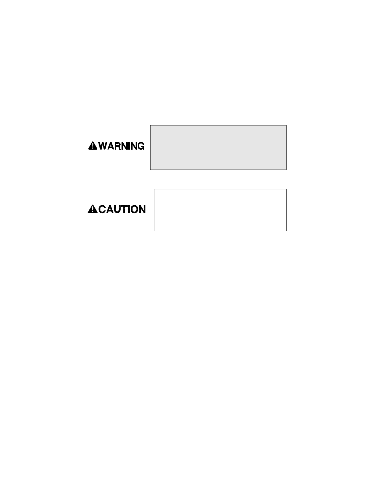
A shaded box with the word “Warning” on its left
denotes a warning. A warning alerts you of a hazard
that may cause injury to yourself or others. Be sure
to follow any instructions contained within a warning
and exercise extreme care while performing the task.
The symbol at the left and the bold text contained
within a box denotes a caution and is used to inform
you that property damage may occur. Be sure to
exercise special care and follow any instructions
contained within a caution.
NOTE 1: Alerts you to additional information about a subject. A number
immediatly after the word note is included for reference within each
subject.
4
Page 13

Vehicle Description and Specifications
Describes the Vehicle and Its Standard Specifications
Page 14
SECTION 1
Vehicle Description
This manual applies to vehicles with the same model and serial numbers listed on the front
cover.
This vehicle is designed for driving on smooth surfaces in and around industrial plants,
nurseries, institutions, motels, mobile home parks, and resorts. It is not to be driven on public
highways.
The maximum operating speed of this vehicle is the speed that the vehicle may travel on a
level surface with no load. Exceeding this speed, while traveling down an incline or on a level
surface, may result in steering difficulty, motor damage, and/or loss of control of the vehicle
that may result in injury and/or property damage. It is just as important that the vehicle not
be towed faster than 5 mph.
This vehicle conforms to requirements for Type E vehicles as described in O.S.H.A. Standard
Section 1910.178 (Powered Industrial Trucks) and with all applicable portions of the American
National Standard for Personnel and Burden Carriers (ANSI B56.8), in effect at the time of
manufacturing.
The model and serial number for this vehicle are imprinted on a decal located on the inner left
side of the front cowl. The vehicle serial number is stamped in the frame, under the drivers
seat to the right of the safety interlock switch on the MX-600, on the frame tube to the left of
the motor on the SS5-34, and on the left frame rail under the seat on the SS5-36 and SS5-46.
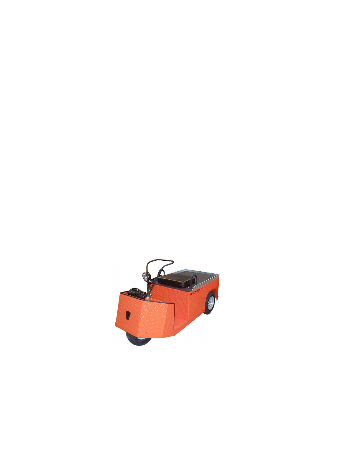
Taylor-Dunn Mfg. Standard Model SS5-34 shown. This is one of the
vehicles described and covered by this manual.
1-2
Page 15
Standard Specifications
ITEM SPECIFICATION
Standard Dimension (SS5-34) 194.3 x 72.4 x 106.7 cm
(MX-600) 217.4 x 81.3 x 104.1 cm
(SS5-36) 219.7 x 76.2 x 104.1 cm
(SS5-46) 226.1 x 76.2 x 104.1 cm
Bed Size (MX-600) 68.6L X 76.2W cm (27L X 30W in)
(SS5-34) 59.7L X 69.9W cm (23.5L X 27.5W in)
(SS5-36, 5-46) 49.5L X 73.7 cm (19L X 30W in)
Dry Weight (SS5-36 & MX-600) 352 kg (775 lbs)
(Including Batteries) (SS5-34) 332 kg (713 lbs)
(SS5-46) 376 kg (830 lbs)
Turning Radius (MX-600) 205 cm (81 in)
(SS5-34 & SS5-36) 190.5 cm (75 in)
(SS5-46) 208.7 cm (81 in)
Brakes (SS5-36, 5-46, MX-600) 2-Wheel Rear Drum (Mechanical Standard)
(SS5-34) Drive Line Brake Band
Motor 24 Volts, 4.5 hp @ 935 rpm
Tires 4.80 X 8 Load Range B Pnuematic
Tire Presure 50 psi max.
Length Width Height
76.5 x 28.5 x 42 in
86 x 32 x 41 in
86.5 x 30 x 41 in
89 x 30 x 41 in
Maximum Load (MX-600, SS5-36, 5-34) 272 kg (600 lbs.)
(On Level Surface) (SS5-34) 227 kg (500 lbs)
Battery Four 217 AH, 6 Volt
Charger 120V, 12Amp, 60hZ AC Input
Gradeability 15% (Empty)
Maximum Speed (Empty) 16 kmh (10 mph)
24V, 25Amp DC Output
5% (Loaded)
1-3
Page 16

SECTION 1
Taking Delivery of Your Vehicle
You should inspect your vehicle immediately after delivery. Use the following guidelines
to inspect your vehicle for obvious problems:
n Examine the contents of all packages and accessories that may have come in
separate packages with the vehicle.
n Make sure everything listed on the packing slip is there.
n Inspect all components of the packages for signs of damage.
n Examine all visible wires and the vehicle for obvious signs of damage.
n Check that all wire connections, battery cables, etc., are secure.
n Check battery cells to be sure they are filled.
n Check the tire pressure, tightness of lug nuts and for signs of obvious
damage or wear.
n Check the operation of each of the following controls. They should operate
smoothly without sticking or requiring undue effort:
• Accelerator Pedal
• Brake Pedal
• Forward/Reverse Selector Switch
• Battery Disconnect Switch (Optional)
• Key-Switch
• Parking Brake
• Steering Wheel
• Horn
• Lights
What To Do If You Find a Problem
If there is a problem with the vehicle or any of the accessories that may have been
shipped with the vehicle, file a claim with the carrier immediately. The claim must be filed
within 48 hours of receiving the vehicle and the accessories. Forward a copy of the claim
to your local Taylor-Dunn dealer.
The only personnel authorized to repair, modify, or adjust any part of this or any TaylorDunn vehicle is a factory authorized service technician. All other personnel are expressly
prohibited from working on, repairing, adjusting, or modifying any part of this or any
Taylor-Dunn vehicle.
Do not attempt to modify or repair any part of this
vehicle unless you are authorized to do so. Incorrect
repairs may result in injury to yourself or others.
Incorrect or unauthorized repairs will result in the
invalidation of your warranty.
1-4
Page 17
Safety Rules and Operational Information
Safety rules, guidlines, control functions, operating guidlines and
storage information
Page 18
SECTION 2
Safety Rules and Guidelines
Responsibilities
It is the responsibility of the owner to ensure that the operator understands the various
controls and safety operations of this vehicle, as well as, obeying the following safety rules
and guidelines:
This vehicle was not designed to be driven on public
highways. The size, speed, and maneuverability of this
vehicle would cause a serious traffic hazard on a public
highway. Driving this vehicle on public highways can
result in serious injury or even death.
This vehicle may overturn if turned sharply while driving
at high speeds on inclines or level surfaces.
2-2
Page 19

Safety Rules
This vehicle is designed to be driven over smooth surfaces in and around places such as
warehouses, nurseries, motels, parks, and resorts. Operators should read the safety rules,
and guidelines below before operating this vehicle:
n Do not drive this vehicle unless you are a qualified operator.
n Keep all body parts inside the vehicle at all times.
n Drive slowly when making turns, especially if the ground is wet, slippery, or
when driving on an incline.
n Drive only on level surfaces or on inclines of no more than 10% (5.6
degrees).
n Do not drive over loose objects, holes, or bumps.
n Observe all traffic regulations and speed limits.
n Maintain a safe distance from all objects.
n Keep the vehicle under control at all times.
n Yield the right of way to pedestrians and all emergency vehicles.
n Do not overtake or attempt to pass another vehicle at intersections, blind
spots, or other dangerous locations.
n Keep a clear view ahead at all times.
2-3
Page 20

SECTION 2
Driver Training Program Guidelines
The owner of this vehicle is responsible for conducting an “Operator Training Program” for
all those personnel that will be operating this vehicle. The program should not be condensed
for those claiming to have previous vehicle operation experience.
NOTE: Successful completion of the “Operator Training Program” should be
required for all personnel that will operate this vehicle.
The “Operator Training Program” should include the following:
n Operation of the vehicle under normal circumstances. (Associated with your
particular environment.)
n How to safely operate the vehicle.
n How to safely transport cargo and personnel.
n All safety rules contained in this manual.
n Proper operation of vehicle controls.
n Operator maintenance checks.
n A test on the operators ability to identify and operate the controls installed on
this vehicle.
n A driving test.
Driver Qualifications
Who is Qualified to Drive?
A qualified driver is a person who has successfully completed the owners “Operator Training
Program” and has shown through testing to posses the visual, auditory, physical, and
mental abilities to safely operate this vehicle.
Minimum Requirements
The following are the minimum requirements necessary to qualify as an operator of this
vehicle:
n Demonstrate a working knowledge of each control
n Understand all safety rules and guidelines as presented in this manual
n Know how to load and unload cargo
n Know how to properly park this vehicle
n Demonstrate the ability to handle this vehicle in all conditions
2-4
Page 21

Vehicle Controls
The following text describes the use and location of each of the controls available on this vehicle:
Key-Switch
For the SS5-36, 5-46 and SS5-34 the key-switch, located on the right side of the instrument panel, turns
on the vehicle. On the MX-600, the key switch is located on the instrument panel to the right of the
seat. Rotate the key clockwise to turn the vehicle on, counterclockwise to turn the vehicle off.
The key-switch should be in the off position whenever the operator leaves the driver's seat.
This switch is also designed to secure and disable the vehicle. You can remove the key ONLY when the
key-switch is in the OFF position.
Forward/Reverse Lever
The forward-reverse rocker switch is located on the dash on the SS5-34, 5-36 and 5-46 and on the panel
to the right of the seat on the MX-600. It determines the direction of travel of the vehicle. Push the top
of the switch to make the vehicle go forward. Push the bottom of the switch to go in reverse. DO NOT
SHIFT from forward to reverse or vice-versa while the vehicle is in motion. Make sure the vehicle is
completely stopped before shifting. The forward-reverse switch has a neutral position. The switch
should be in the neutral position with the park brake set whenever the operator leaves the driver's seat.
Accelerator Pedal
The accelerator pedal is located to the right of the brake pedal. It controls the speed of the vehicle, is
designed for right foot operation only and operates the same way as the accelerator pedal in an
automobile. Depress the pedal to speed the vehicle up. Release the pedal to slow down.
Seat Interlock Switch
A switch located under the driver's seat disables the vehicle when the driver leaves the seat. The
driver must be seated for the vehicle to operate.
The seat switch is optional on the SS5-34.
2-5
Page 22

SECTION 2
Foot Brake Pedal
The foot brake pedal located to the left of the accelerator pedal and is for operation with the right foot
only. It works the same as the brake in an automobile. Applying pressure to the brake pedal slows the
vehicle according to the amount of pressure applied. Removing your foot from the pedal releases the
braking action.
Steering
The standard steering system is a loop tiller type. To turn right, turn the tiller to the left. To turn left,
turn the tiller to the right .
Optional steering wheel - The steering wheel and steering system are similar to an automobile. To turn
right, turn the steering wheel clockwise. To turn left, turn the steering wheel counter-clockwise.
Park Brake
The parking brake is part of the foot brake pedal. To set the parking brake, push down on the lower
half of the brake pedal until the pedal locks in the down position. To release the park brake, apply
pressure on the upper half of the brake pedal until the pedal disengages from the locked position.
Horn Button
The horn button is located on the left side of the floor board and is designed for left foot operation.
Depress the button to sound the horn, release it to turn it off.
Headlights and Accessories (Optional)
The headlight switch is located of the left side of the instrument panel. An accessory switch, if any, is
adjacent and to the right of it. On the MX-600 these switches are located on the instrument panel to
the right of the seat.
Hour Meter (optional)
The hour meter is located to the right of the battery status indicator. This tracks the number of hours
the vehicle has been in operation. On the MX-600, it is located on the kick panel just to the right of the
seat.
Battery Status Indicator
The battery status indicator is located to the right of the accessory switch. The normal operating
range is in the green zone. The vehicle needs charging if it is in the yellow zone to the left. If it is in the
red zone to the left, the vehicle should be taken out of service immediately to be charged. On the MX600 it is located on the kick panel just to the right of the seat.
2-6
Page 23

Guidlines for Vehicle Operation
The following text contains the guidelines for driving, loading, unloading, parking, and
towing the vehicle:
Driving
n Slow down and sound the horn when approaching a corner or a blind
intersection.
n There is no horseplay or dangerous driving allowed while operating the
vehicle.
n Do not drive this vehicle in hazardous areas, unless this vehicle is approved
and labeled for such operation.
n Report any accidents or vehicle problems to your supervisor immediately.
Loading and Unloading
n Do not load cargo that can easily fall off this vehicle.
n Do not exceed the load capacity of this vehicle.
n Do not carry more than the maximum number of passengers allowed for this
n Be extra careful when handling cargo that is longer, higher, or wider than the
Parking
n Park the vehicle by turning the key-switch off, placing the forward/reverse
n If parking on an incline, block the wheels to prevent movement.
n Do not block fire aisles, emergency equipment, or stairways.
vehicle.
vehicle.
lever in neutral, and setting the park brake.
2-7
Page 24

SECTION 2
Towing
n Attach the tow strap to the front bumper tow-bar and place the forward/
n Use another driver to steer and control the speed of the vehicle, while it is
n The driver of the towed vehicle is to maintain a safe distance from the
n Do not exceed 5 mph or carry any passengers while towing the vehicle.
reverse switch in neutral.
being towed.
towing vehicle and use the brakes when the towing vehicle slows or stops.
NOTE: This vehicle is not to be towed using a commercial tow truck. It may
be towed either behind another vehicle of the same type or on a flat bed tow
vehicle.
Exceeding the towing speed limit or carrying passengers
can result in damage to the vehicle and serious injury. At
no time are passengers allowed in the towed vehicle. The
only personnel allowed to ride in the towed vehicle is the
operator/driver.
All cargo must be removed from the vehicle prior to towing.
2-8
Page 25
Maintenance and Service Procedures
Maintenance and Service Information, Including Lubrication
Information, Scheduled Maintenance, and Disassembly
Page 26

SECTION 3
Introduction to Maintenance
This section contains the procedures necessary to repair and service your vehicle.
You will also find periodic maintenance information and guidelines to follow before
doing any kind of maintenance or service on this vehicle. Vehicle maintenance or
repairs should only be performed by a qualified mechanic.
This section contains the following:
n Maintenance Guidelines
n Maintenance Guidelines for Vehicles Used in Severe Conditions
n Maintenance Checklist
n Lubrication Chart
n Troubleshooting Guide
n Detailed Maintenance Procedures.
Maintenance Guidelines
n Allow only qualified and authorized personnel are to maintain, repair,
adjust, and inspect the vehicle.
n Before starting any repairs or maintenance, immobilize the vehicle by
turning the key switch off, removing the key, and setting the park brake.
n Disconnect both of the main battery leads before working on or
disconnecting any electrical component or wire.
n Block the chassis with jack stands before working under a raised
vehicle.
n Conduct vehicle performance checks in an authorized area where safe
clearance exists.
n Before starting the vehicle, follow the recommended safety procedures
in Section 2, “Safety Rules and Operational Information.”
n Avoid fire hazards and have fire protection equipment present in the
work area. Do not use an open flame to check level or leakage of battery
electrolyte. Do not use open pans of fuel or flammable fluids for cleaning parts.
n Ventilate the work area properly.
n Regularly inspect and maintain in a safe working condition, brakes,
steering mechanisms, speed and directional control mechanisms, warning
devices, lights, governors, guards, and safety devices.
3-2
Page 27
n Inspect and maintain battery limit switches, protective devices, electrical
conductors, and connections in conformance with Taylor-Dunn’s recommended procedures.
n Keep the vehicle in clean condition to minimize fire hazards and facilitate
detection of loose or defective parts.
Periodic maintenance and service must be performed on this
vehicle. Failure to complete these scheduled maintenance and
service procedures can result in personal injury, and/or property
damage. It is the owner and/or operators responsibility to insure
that proper service and maintenance is performed on the vehicle,
described in this manual.
Maintenance Guidelines for Vehicles Used in Severe
Conditions
The following list is meant as a guide and is not all inclusive:
SEVERE CONDITIONS refer to operation:
n In extreme temperatures
n On bumpy, dusty, or ill maintained roads
n In excessively wet areas
n In corrosive or contaminated areas
n At or near maximum capacity for more than 50% of the operating time
n On multiple shifts
Severe Duty Maintenance Guidelines:
If this vehicle is operate in severe conditions all maintenance items listed in the Periodic
Maintenance Table should be carried out twice as often as stated. In addition, the whole
vehicle should be inspected monthly for signs of damage and repaired immediately.
3-3
Page 28
SECTION 3
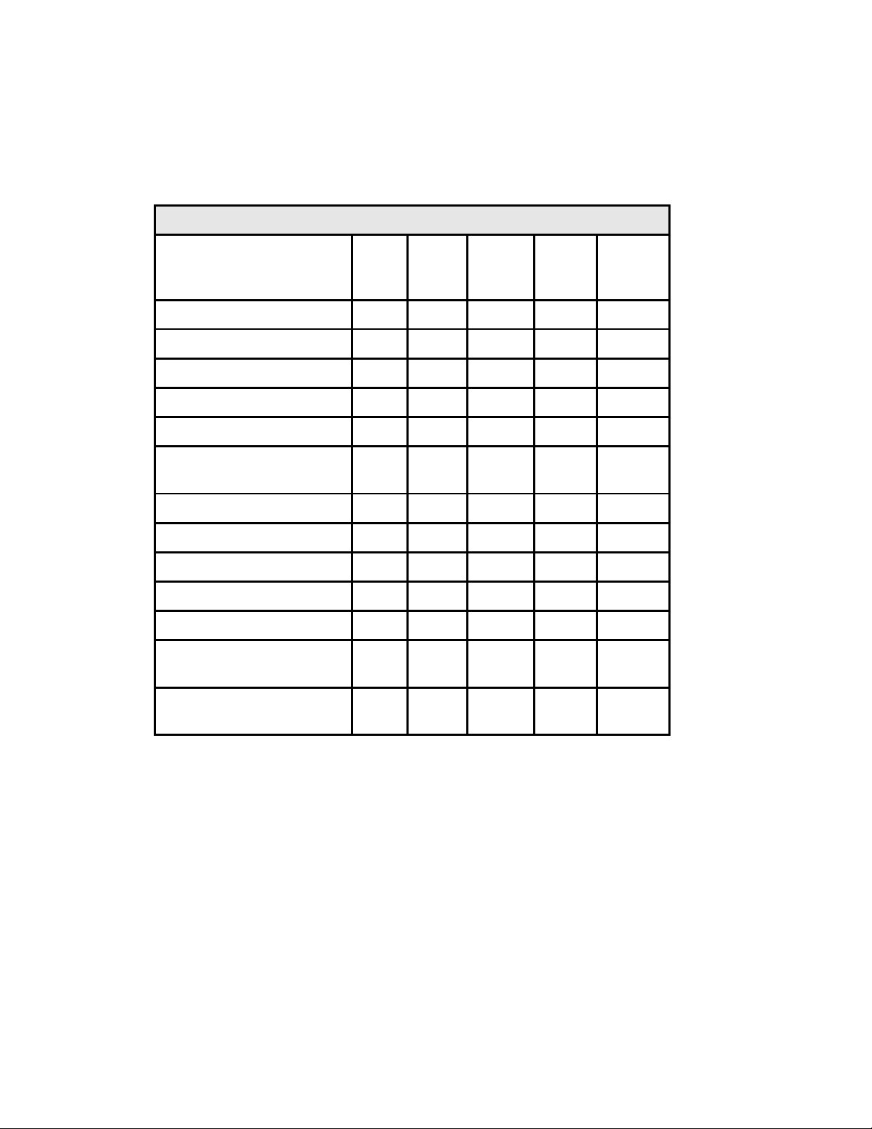
Periodic Maintenance Table
Periodic Maintenance Checklist
Maintenance Item
Check Condition of Tires X
Check and Fill Batteries X
Check Brake System X
Check Steering System X
Lubricate Vehicle X
Clean and Tighten All Wire
Connections
Wash and Service Batteries X
Check Park Brake X
Check Front Wheel Bearings X
Check Rear Axle Oil X
Change Rear Axle Oil X
Check and Tighten all Nuts and
Bolts
Weekly
(20hrs)
Monthly
(80hrs)
Quaterly
(250hrs)
X
Semi -
Annual
(500hrs)
Annualy
(1000hrs)
X
Clean and Repack Front Wheel
Bearings
X
3-4
Page 29
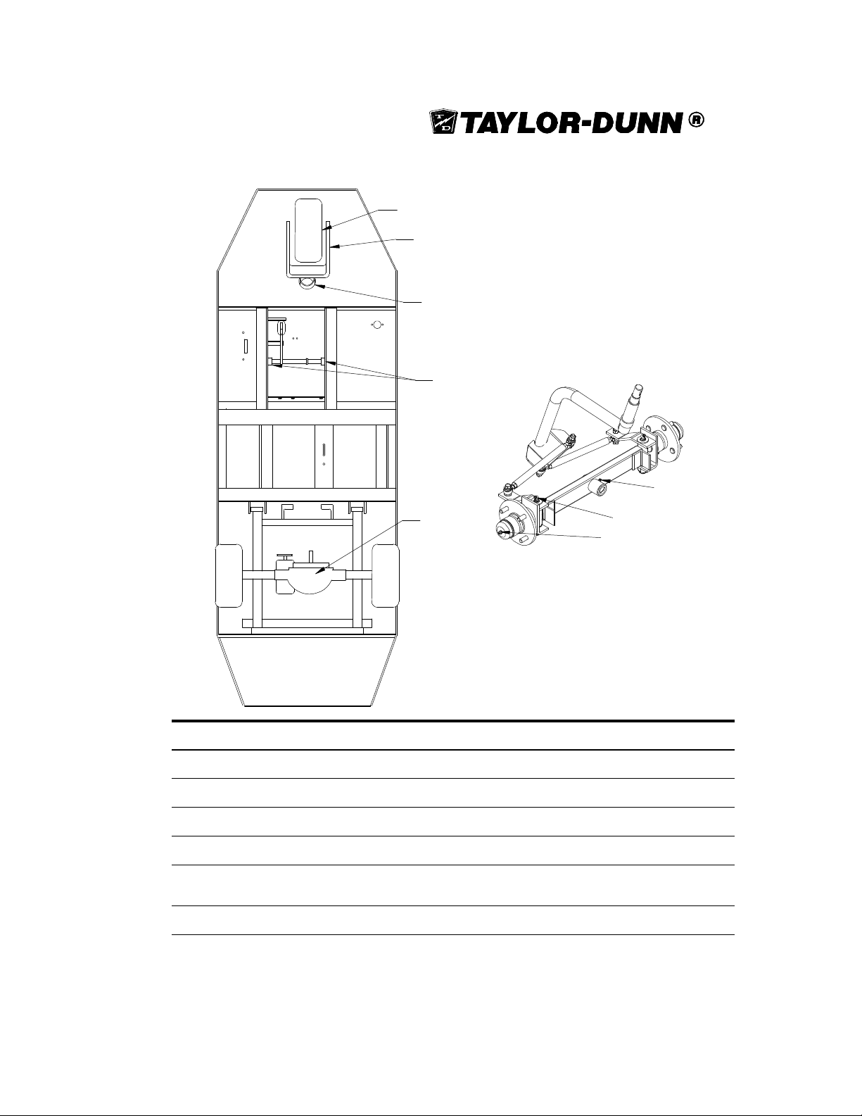
Lubrication
1
2
3
4
7
5
6
1
SS5-46 Front Axle
# Description Locations Lubricant
1 Front Wheel Bearing 1 High Temp Wheel Bearing Grease
2 Front Fork Pivots 2 General Purpose Grease
3 Steering Collars 1 General Purpose Grease
4 Brake Shaft Collars 2 General Purpose Grease
5 Rear Axle Differential 1 SS-536, SS 5-46, MX-600, SAE 30 Motor Oil
6 King Pin (SS5-46) 2 General Purpose Grease
SS5-34, SAE 140 API GL-5 Gear Oil
3-5
Page 30

SECTION 3
Trouble shooting Guide
Symptom Probable Cause
Steering Pulls in One Direction Worn Wheel or Collar Bearing
Hard Steering Dry Lube Points in Steering Linkage
Lack of Power or Slow Operation Brakes or Parking Brake Dragging
Abnormal Noise Worn Drive Gears or Bearings
Oil Leak in Rear Bearing Area Rear Wheel Bearing and/or Gasket Failed
No Brakes Brakes out of Adjustment
Brake Pedal Low Brake Worn (1/16-inch Wear Limit)
Braking Power Low Brake Worn (1/16-inch Wear Limit)
Low Tire Pressure
Broken or Missing Spring
Bent Frame or Fork
Low Tire Pressure
Worn Drive Gears or Bearings
Loose or Worn Drive Belt
Low Battery
Defective Speed Controller
Defective or Worn Motor Brushes
Loose or Worn Drive Belt
Worn Front/Rear Axle Bearings
Loose Lug Nuts
Motor Bearings Worn
Drive Over Filled
Brake Pedal Linkage Binding or Broken
Brakes Out of Adjustment
Brakes Out of Adjustment
Brake Pedal Linkage Binding
3-6
Page 31

NOTES
3-7
Page 32
SECTION 3
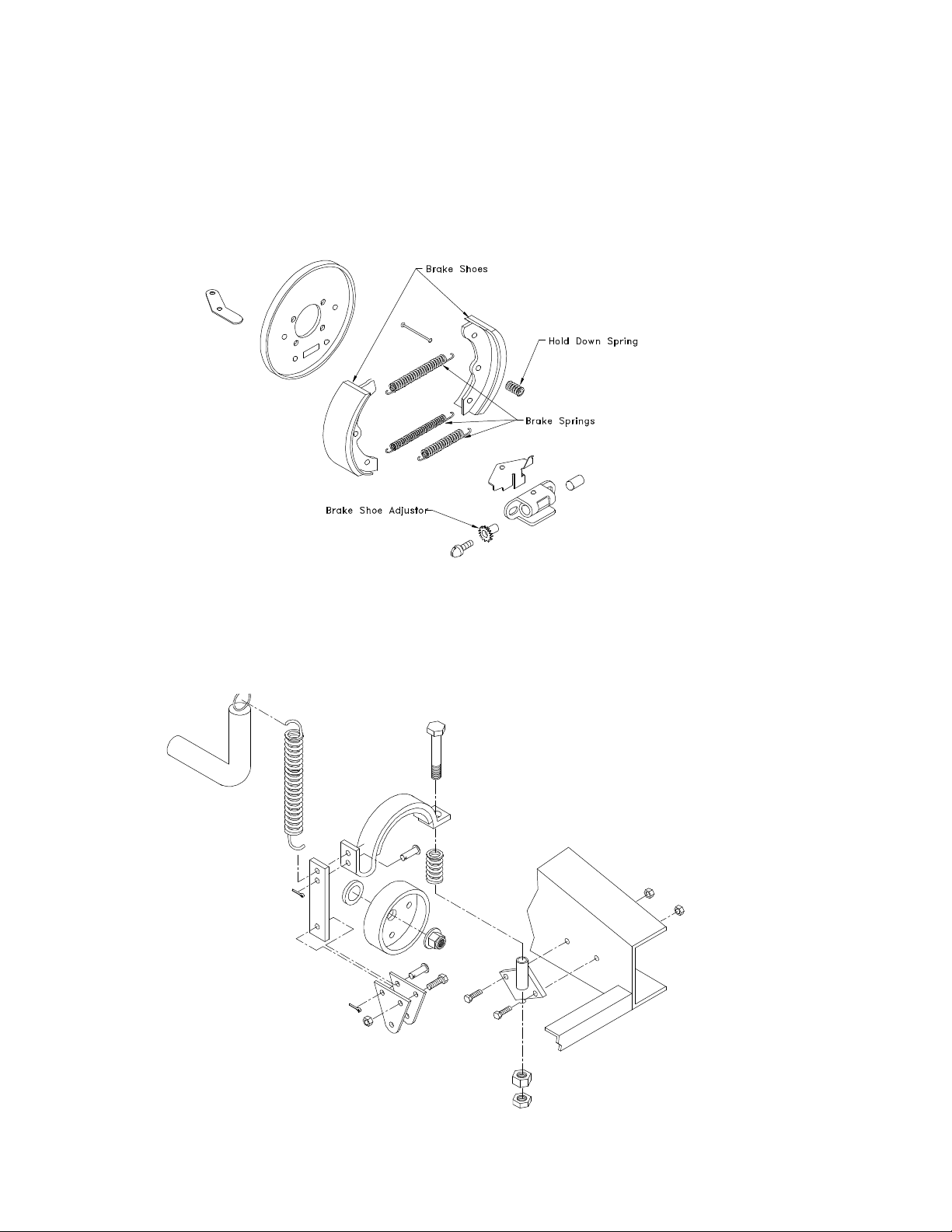
MECHANICAL REAR DRUM BRAKES
(STANDARD ON SS5-36, SS5-46 & MX-600)
DRIVE LINE BRAKE BAND (ST ANDARD
ON SS5-34)
3-8
Page 33
Brakes
This section covers the installation and repair of the brake systems that are installed on
the SS5-34, SS5-36, SS5-46 and MX-600. These vehicles come equipped either with the
mechanical rear drum brakes (found on the SS5-36, SS5-46 & MX-600) or the drive line
brake band (found on the SS5-34).
Be fully aware of the brake system installed on the vehicle before continuing.
The OEM does not supply asbestos fiber-brake pads/shoes with
this or any vehicle. However, there is the possibility that the
OEM brake pads/shoes were replaced with those containing
asbestos fibers. Since this possibility does exist the brake pads
should be handled as if they do contain asbestos.
Never use compressed air or dry brush to clean brake
assemblies. Use an OSHA approved vacuum cleaner or any
alternate method approved by OSHA to minimize the hazard
caused by airborne asbestos fibers and brake dust.
Do not grind, sand, break, or chisel the brake pads/shoes as
this will cause unnecessary dust possibly releasing asbestos
fibers into the air.
Always wear a resperator, protective clothing and a face shield
when working on the brake system.
Inhaled asbestos fibers have been found to cause cancer and
respiratory diseases.
Do not drive the vehicle if any worn or broken part is detected in
any part of the brake system. The cause of the damage must be
repaired immediately.
NOTE: The park brake system is similar regardless of the brake
system installed in the vehicle.
NOTE: To apply the park brake, apply pressure to the lower half
of the foot pedal until it locks in place. To release the park brake
apply pressure to the upper half of the pedal.
3-9
Page 34
SECTION 3
SS5-34 Brake System
The SS5-34 comes standard with a mechanical drive line brake. The brake drum is
attached to the pinion shaft. The brake band is anchored to the frame of the vehicle
and attached to the brake pedal by the brake lever arm.
Here we will cover how to remove and service the mechanical drive line brake
system. Refer to the illustration in the beginning of this section
There are springs attached to parts of this braking
system. There is a possibility that these springs may
break or slip out of their mounting holes while
servicing the brake. To prevent possible injury to the
head or face a face shield should be worn whenever
you are working on or around the brake band.
Adjusting the Brake Band
The brake band my need to be adjusted periodically to compensate for the normal wear
of the brake lining or pad on the band. To adjust the brake band, do the following:
1. Park the vehicle in a clean, flat area and remove the key.
2. Block the tires to prevent the vehicle from accidently moving.
3. Lift and secure the deck.
4. Tighten the brake band anchor bolt until brake pad engages the drum
with sufficient force to stop the vehicle when the brake pedal is
halfway down to the floor board.
NOTE: With this adjustment, the parking brake is automatically
adjusted, so that when the lower slot of the pedal engages the
locking angle welded to the frame proper braking force is
applied. As the lining wears, the pedal travel will increase to
the point where the upper slot must engage the locking angle
to provide adequate braking force. The brake band must be
adjusted before lining wear reaches the point where
engagement in the upper slot fails to provide adequate braking
force.
3-10
Page 35
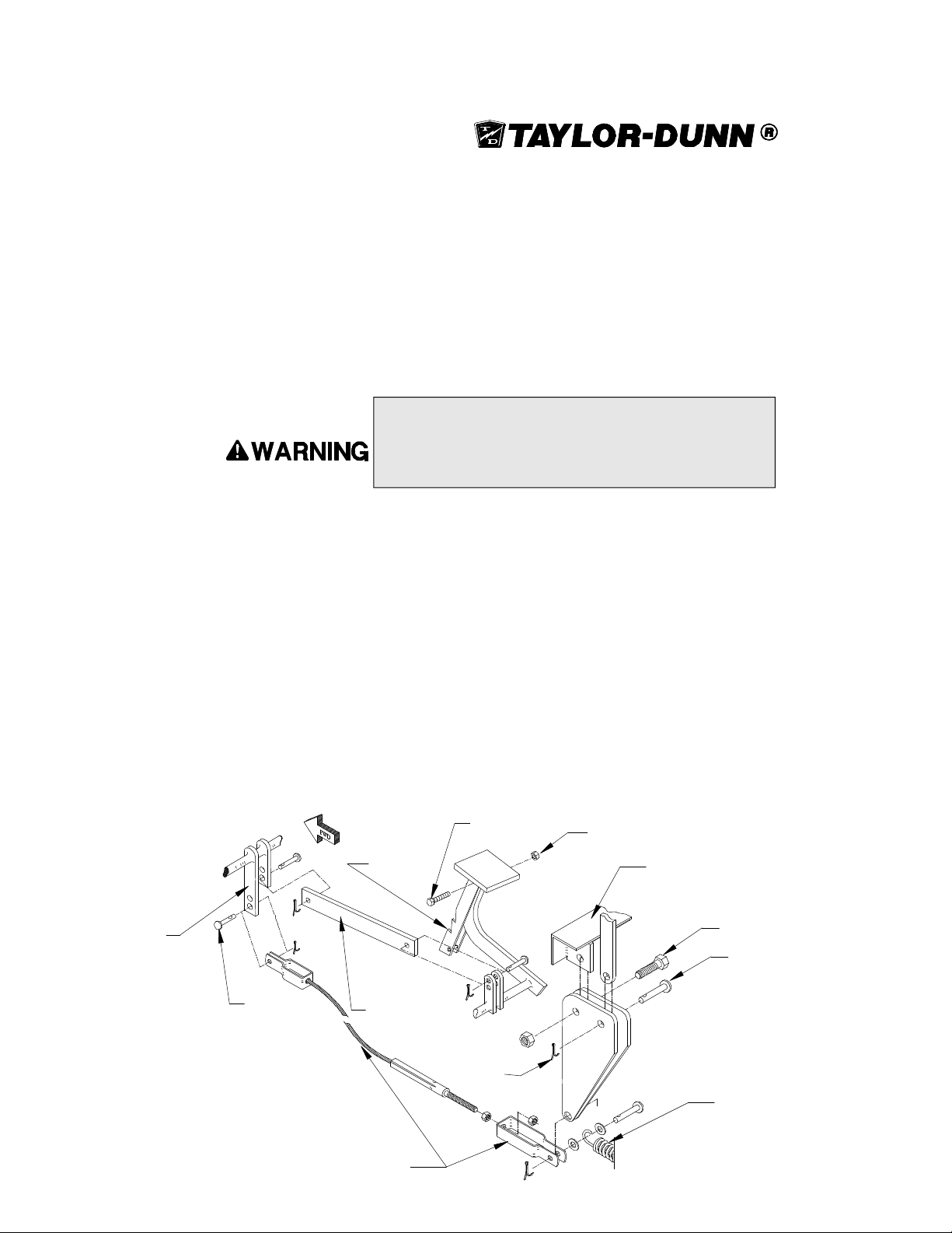
Adjusting the Brake Cable
The brake cable length must be adjusted so that the brake lever arm (located below
the brake drum) is pivoted rearward as far as possible.
To adjust the brake pedal linkage:
1. Park the vehicle on a clean level surface and block the rear wheels to
prevent movement.
2. Raise the front of the vehicle and support it with jack stands.
Always use a lifting strap, hoist and jack stands of adequate
capacity to lift and support the vehicle. Failure to use lifting and
supporting devices of rated load capacity to support the vehicle
may result in serious injury and property damage.
3. Loosen the jam nut on the brake cable.
4. Tighten the adjusting bolt until the brake cable is slightly tight.
NOTE: There should be some slack in the brake cable. Do
not overtighten the brake cables. Overtightening of the
adjusting nut and the cables will result in brake drag and
premature failure of the brake shoes.
Clevis Pin
5. Tighten the jam nut against the clevis and lower the vehicle.
6. Check the brake pedal to see that the park brake lock engages with
medium pressure on the lower half of the pedal.
7. Release the park brake and test drive the vehicle checking for brake
drag.
8. Check the travel of the brake pedal. It should have about 1/2” of travel
before it engages the brakes.
Park Brake
Lock
Brake Pedal
Connecting Link
Brake Pedal
Cotter Pin
Nut
Frame Ref.
Hex Head Cap
Screw
Clevis Pin
Spring
Brake Cable
3-11
Page 36

SECTION 3
Removing the Brake Assembly
In order to remove the brake assembly refer to the following instructions:
1. Park the vehicle on a level surface and block the tires to prevent any
accidental movement.
2. Remove the key and place the forward/reverse switch in the neutral
position.
3. Remove the deck board and seat from the vehicle.
4. Remove the spring from the lever bar.
5. Remove the cotter pin and the clevis pin from the brake band.
6. Remove the brake band anchor bolt and brake band.
7. Remove the brake drum from the pinion shaft.
8. Clean and inspect the brake band and brake drum. Replace all worn
parts as needed.
NOTE: If the brake lining or pad is 1/16” or less in thickness,
the lining must be replaced. Also, if the brake drum is severely
scored, damaged, or less than 5.85” in diameter it must be
replaced with a new brake drum.
NOTE: If the brake drum is glazed or lightly scored. The
glazing or scoring should be removed from the drum by
sanding.
9. Reinstall the brake assembly by doing steps 1 through 7 in reverse
order.
10. Adjust the brake band.
3-12
Page 37
SS5-36, SS5-46 and MX-600 Brake
System
Adjusting the Brake Pedal Linkage
To adjust the brake pedal linkage, refer to the following procedures.
1. Park the vehicle on a clean level surface and block the rear wheels to
prevent movement.
2. Raise the front of the vehicle and support it with jack stands.
3. Loosen the jam nut on the brake linkage.
Always use a lifting strap, hoist and jack stands of adequate
capacity to lift and support the vehicle. Failure to use lifting and
supporting devices of rated load capacity to support the vehicle
may result in serious injury and property damage.
4. Tighten the adjusting bolt until the brake cables are slightly tight.
NOTE: There should be some slack in the brake cables. Do
not overtighten the brake cables. Overtightening of the adjusting
bolt and the cables will result in brake drag and premature
failure of the brake shoes.
5. Tighten the jam nut against the clevis and lower the vehicle.
6. Check the brake pedal to see that the park brake lock engages with
medium pressure on the lower half of the pedal.
7. Release the park brake and test drive the vehicle checking for brake
drag.
8. Check the travel of the brake pedal. It should have about 1/2” of travel
before it engages the brakes.
3-13
Page 38
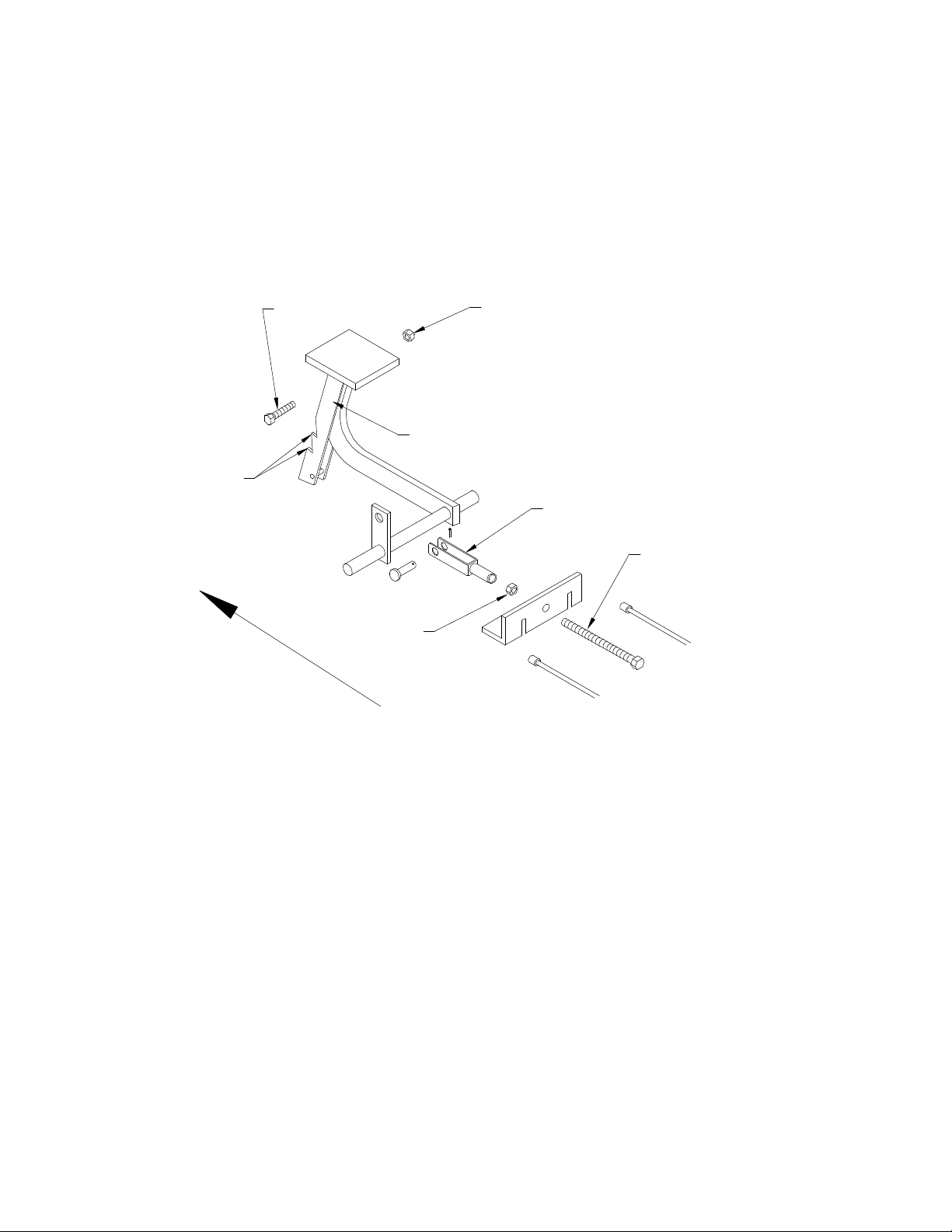
SECTION 3
Inspecting and Replacing the Park Brake Lock(All
Models)
Mounting Bolt
Park Brake Lock
Points
Forward
Jam Nut
Foot Brake Assembly: Shown is the brake pedal, and how it connects to the
brake cables on the SS5-36, SS5-46 and MX-600.
Locknut
Clevis
Adjusting Bolt
3-14
Page 39
Replacement and Wear of Park Brake Lock (All Models)
In the following procedure, you will be told how to replace the Park Brake Lock
assembly:
1. Park the vehicle on a clean flat surface and block the rear wheels to
prevent movement.
2. Turn the key off and place the forward/reverse switch in neutral.
3. Disconnect the main positive and negative terminals from the battery.
4. With the brake pedal in its fully extended position, remove the 1/2” bolt
and locknut from under the pedal.
Always use new locknuts and bolts. Locknuts and bolts become
less effective if used more than once. If the locknuts or bolts
holding the brake to the drive come loose, serious injury may
occur.
5. Remove the pedal and park brake lock assembly from the brake arm.
6. Install a new pedal and park brake lock assembly, following steps 4
through 5 in reverse order. (Substituting the word install for remove in
steps 4 and 5.)
In the following procedure, you will be told how to check the Park Brake Lock for
Wear.
1. After removing the park brake lock, inspect the points of the notches
on the park brake lock.
2. If they are broken or worn, replace the assembly with a new one as
instructed above.
Wear Limits:
If you apply the park brake lock and it does not catch or slips easily it must be
replaced.
Press on the lower half of the pedal if the park brake lock engages with little
effort on the upper most notch. Check the linkage adjustments and adjust as
needed.
3-15
Page 40
SECTION 3
SS5-36, SS5-46 and MX-600 Rear Brakes
The rear brakes are mechanical, auto adjusting, drum brakes and require no periodic
adjustments to ensure safe operation. Servicing of these brakes consists of replacing
the brake drum and brake shoes when they become worn.
In this section, we will cover how to inspect and replace the brake drum and shoes.
Wear Limit:
Brake Shoes-
Measure the brake shoe at various locations. It should be thicker than 1/16” at
its thinnest point. If you measure 1/16” or less at any given point the shoes
must be replaced.
Brake Drum-
The brake drum should be replaced if it is scored or damaged. The presence of
grooves or damage on the inside diameter of the drum can effect the braking
capabilities of the vehicle.
Rear brake drum and shoe.
3-16
Page 41
Replacing the Brake Drum
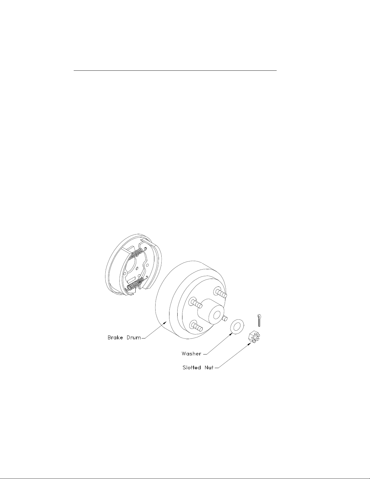
To replace the rear brake drum, use the following procedure:
1. Raise the rear of the vehicle one side at a time. Placing jack stands
under the vehicle to support it. Do not Attempt to raise the rear end
by placing jacks or other lifting devices in the center of the rear end.
Always use a lifting strap, hoist, and jack stands of adequate
capacity to lift and support the vehicle. Failure to use lifting and
supporting devices of rated load capacity to support the vehicle
may result in serious injury and property damage.
2. Remove the rear wheel and tire assembly.
3. Remove the cotter pin, castle nut, and washer from the end of the axle
shaft.
4. Remove the brake drum.
5. Inspect the inside of the brake drum for wear or damage. If it is
grooved or damaged, it must be replaced.
6. Visually inspect the brake shoes for wear.
7. Install the new brake drum.
8. Repeat steps 1 through 3 in reverse order.
3-17
Page 42
SECTION 3
Replacing the Brake Shoes
To replace the brake shoes, use the following procedure.
1. Raise the rear of the vehicle until the rear wheels clear of the floor and
place jack stands under the vehicle. Raise the rear of the vehicle one
side at a time. Placing jack stands under the vehicle to support it. Do
not Attempt to support or raise the rear end by placing jacks or other
lifting devices in the center of the rear end.
Always use a lifting strap, hoist, and jack stands of adequate
capacity to lift and support the vehicle. Failure to use lifting and
supporting devices of rated load capacity to support the vehicle
may result in serious injury and property damage.
2. Remove the rear tire and wheel assembly.
3. Remove the cotter pin, castle nut, and washer from the end of the axle
shaft.
4. Remove the brake drum.
5. Inspect the inside of the brake drum for wear or damage. If it is
grooved or damaged it must be replaced.
6. Remove the brake shoe springs
7. Remove the brake shoe hold down spring from each shoe.
8. Remove the brake shoes and adjusting assembly.
9. Disassemble and clean the adjusting screw assembly.
10. Apply Hi-Temp grease to the adjusting screw assembly, hold-down,
and retracting spring contacts on the brake shoes.
11. Install the adjusting screw assembly.
12 Install the brake shoe hold down springs.
13. Install the brake shoe springs.
14. Install the brake drums and tire/wheel assembly.
15. Pump the brakes to automatically adjust the brake shoes.
16. Lower to the ground and road test the vehicle.
NOTE: The brakes may pull slightly to one side or the other
due to the auto self adjustment system. As the brake shoes
wear, one side may automatically adjust before the other.
3-18
Page 43
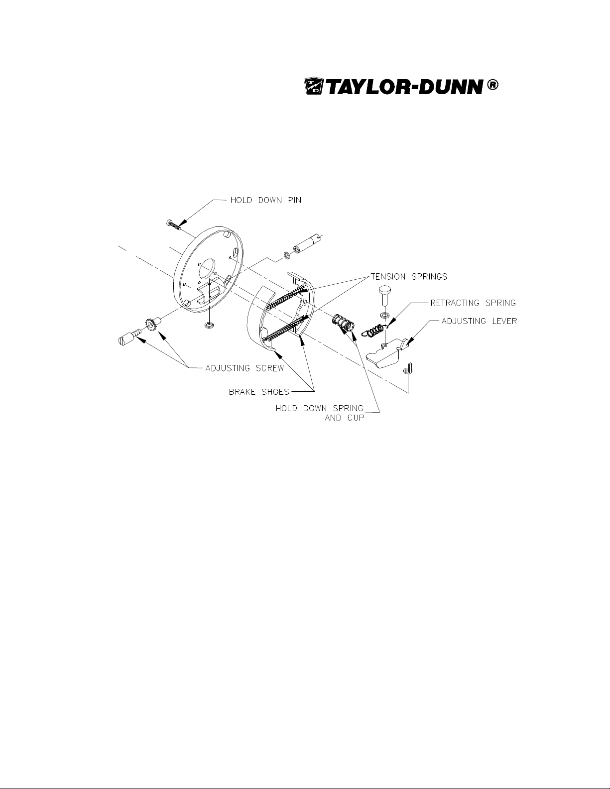
Exploded view of mechanical rear brake assembly.
3-19
Page 44
SECTION 3
Front Fork and Steering
In this section, we will cover how to service and repair the front fork, axle, and
steering assemblies. Included in the steering will be the tiller steering system and
the geared steering system.
The standard steering assembly for the SS5-34, SS5-36, and MX-600 is the Tiller.
Since the Geared option is widely used in these vehicles as well, we included it in
this section. Geared steering is standard on the SS5-46.
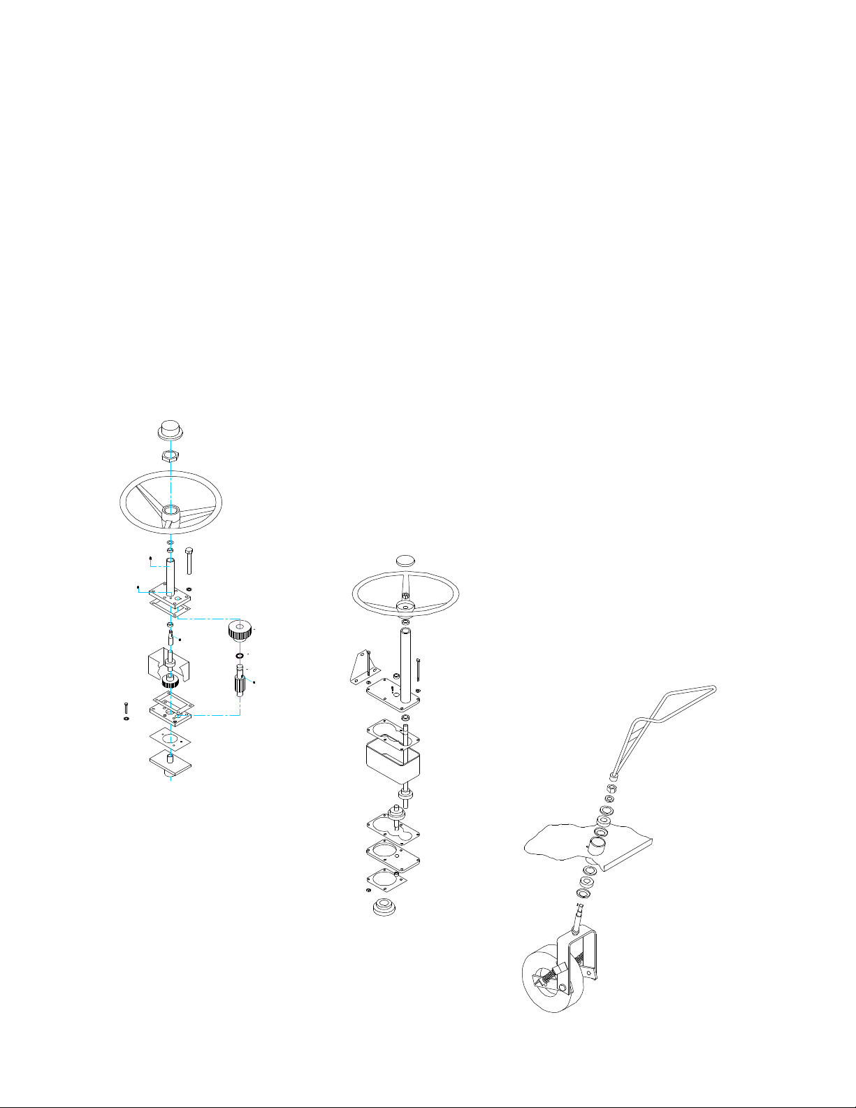
SS5-34
Geared Steering
SS5-36/5-46, MX-
600 Geared Steering
SS5-34, SS5-36
and MX-600
Tiller Steering
3-20
Page 45
Front Fork
Here, we will cover the Front Fork only. The following procedures will cover the
disassembly and repair of the front fork and the axle. ,
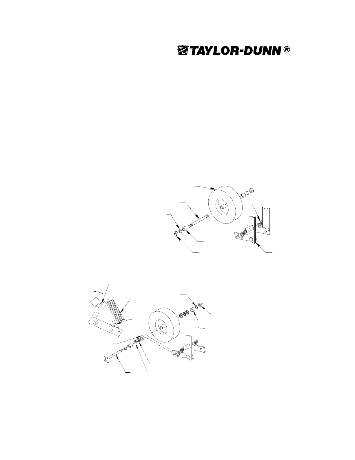
NOTE: There are two types of front axles used within the
serial numbers covered by this manual. The basic instructions
for removing, servicing and installing are the same.
Tire/Wheel Assembly
3/4" NC Washer
TOP
LOCATOR
SPRING
LOWER
LOCATOR
BEARING RACE
AXLE
Axle assembly using one axle nut
Front Axle
WASHER
ROLLER BEARING
OIL
SEAL
Spring
Bumper Spacer
3/4" NC Locknut
Axle assembly using two axle nuts
AXLE NUT
SPACER
Front Fork
3-21
Page 46
SECTION 3
Removing the Front Fork
In order to remove the front fork follow these procedures.
1. Park the vehicle on a clean level surface.
2. Turn the key off and place the forward/reverse switch in the neutral
position.
3. Block the rear wheels to prevent movement.
4. Loosen the spindle mounting nut on the tiller and remove it from the
steering shaft.
5. Remove the woodruff key from its slot on the steering shaft.
5. Remove the locknut located from the top of the steering shaft.
6. Raise the front of the vehicle, allowing the steering shaft to slide
through the cowl.
NOTE : The fork should be supported to prevent it from putting
undue pressure on the lower oil seal, bearing, and bearing
race. This is also done to prevent the fork from falling once it
is removed from the cowl and damaging these parts.
Always use a lifting strap, hoist and jack stands of adequate
capacity to lift and support the vehicle. Failure to use lifting and
supporting devices of rated load capacity to support the vehicle
may result in serious injury and property damage.
7. Support the front fork to prevent it from falling as the front of the
vehicle is raised.
8. Remove the fork, front axle, and springs.
9. Replace seals, bearings, and races as required.
10. Install the new fork in reverse order.
3-22
Page 47
Removing the Front Springs
In order to remove the front springs, follow these procedures:
1. Raise the front of the vehicle and support it with jack stands
Always use a lifting strap, hoist, and jack stands of adequate
capacity to lift and support the vehicle. Failure to use lifting and
supporting devices of rated load capacity to support the vehicle
may result in serious injury and property damage.
2. Compress the front spring and slide it off the top locator.
3. Tilt the spring out away from the fork and remove it from the lower
locator.
4. Install the new spring in reverse order, then lower the vehicle and test
drive.
Removing the Front Axle
This can be done with the fork still in the vehicle or while it is removed. To remove
and replace the front axle assembly, use the following procedure.
1. Raise and support the front of the vehicle.
Always use a lifting strap, hoist, and jack stands of adequate
capacity to lift and support the vehicle. Failure to use lifting and
supporting devices of rated load capacity to support the vehicle
may result in serious injury and property damage.
2. Remove the axle nut and washer from the axle.
3. Pull the axle through the fork slowly.
NOTE: Do not let the spacers, oil seals, roller bearings or
bearing races fall out while removing the axle. Be sure that
these parts can be removed without damaging them or letting
them drop to the floor.
4. Install the new axle in reverse order.
3-23
Page 48

SECTION 3
Replacing the Front Wheel Bearings
To replace worn or damaged wheel bearing, follow the procedure below:
1. Park the vehicle on a level surface.
2. Using the appropriate procedure, remove the front wheel from the
fork assembly.
3. Remove the oil seal, bearings and bearing races from the wheel.
4. Install new bearing races, bearings and oil seals.
Always use new locknuts and bolts. Locknuts and bolts become
less effective if used more than once. If the locknuts or bolts
holding the brake to the drive come loose, serious injury may
occur.
5. Install the axle through the fork and wheel.
NOTE: Remember to install the spacers and outer washers
in their proper location while installing the axle.
6. Install and tighten the axle locknut.
7. Tighten the axle locknut until the wheel slightly drags when it is
rotated by hand.
8. Inject grease into the wheel using a grease gun on the hubs grease
fitting.
9. Lower the vehicle and test drive.
Replacing and Adjusting the Front Fork Collar Bearing
In order to replace and adjust the collar bearings, use the following procedure:
1. Park the vehicle on a level surface.
2. Raise the front of the vehicle and support it with jack stands.
3. Using the appropriate procedure, remove the fork and steering tiller.
4. Remove the upper and lower bearing, bearing race, and oil seal.
5. Install the new bearings, races, and oil seals.
6. Install the front fork and the spindle mounting nut.
7. Tighten the spindle mounting nut while rotating the fork manually.
Continue tightening the nut until it requires 2ft-lbs of torque to rotate
the fork assembly.
8. Loosen the nut slowly until the fork turns freely.
9. Install the tiller.
10. Lower the vehicle and test drive.
3-24
Page 49

Optional Geared Steering
Here, we will cover the optional geared steering assembly. This assembly is an
option on all three vehicles.
In this section, we will cover how to remove and service this steering system.
SS5-34 Geared Steering Assembly
In order to disassemble this steering gear box, follow this procedure. Refer to the
illustration on the following page.
1. Park the vehicle on a level surface and block all the wheels.
2. Remove the cap from the center of the steering wheel.
3. Remove the nut from the center of the steering wheel.
4. Remove the steering wheel and woodruff key from the shaft.
5. Remove the 6 bolts from the top cover.
6. Lift the top cover off the gear box, discarding the gasket.
NOTE: The spur gear and shaft may come out of the gear box
when removing the top cover. Do not let the gears drop to the
floor.
7. Remove as much grease as possible from the inside of the gear box
and dispose of it properly.
8. Remove the gear case and clean the remaining grease from the
bottom of the gear box.
9. Remove and discard the lower gasket.
10. Remove the 3 remaining bolts from the bottom of the gear box.
11. Clean all parts except for the gaskets in solvent.
12. Reassemble in reverse order, installing new gaskets.
NOTE: Check the bronze bushings for wear and replace them
as needed.
13. Fill the gear box with grease.
3-25
Page 50
SECTION 3
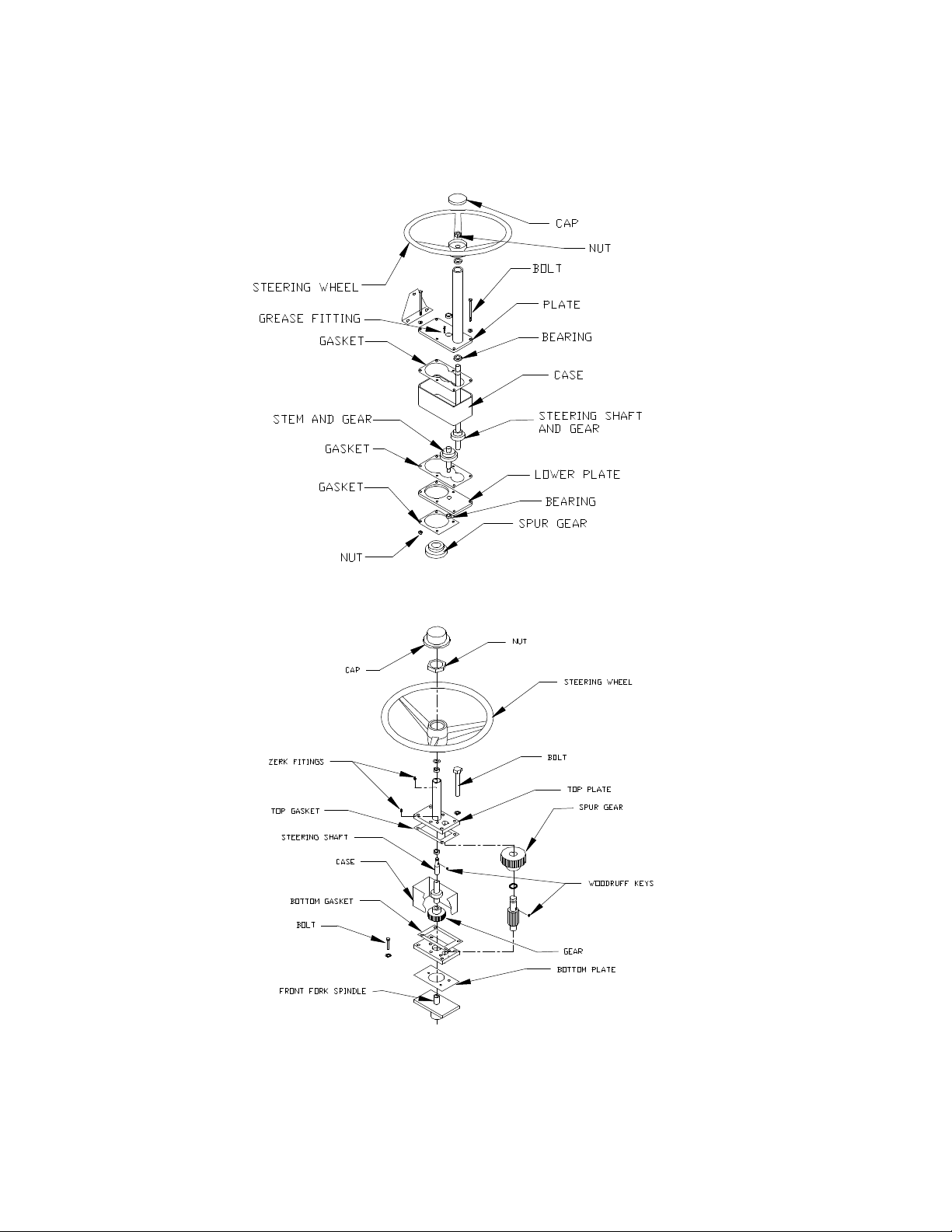
SS5-36, SS5-46 and MX-600 Optional Geared Steering
SS5-34 Optional Geared Steering Assembly
3-26
Page 51

SS5-36, SS5-46 and MX-600 Steering Assembly
In order to disassemble this steering gear box, follow this procedure. Refer to the
illustration on the previous page.
1. Park the vehicle on a level surface and block all the wheels.
2. Remove the cap from the center of the steering wheel.
3. Remove the nut from the center of the steering wheel.
4. Remove the steering wheel from the shaft.
5. Remove the 6 bolts from the top cover.
6. Lift the top cover off the gear box, discarding the gasket.
NOTE: The stem and gear may come out of the gear box
when removing the top cover. Do not let the gear drop to the
floor.
7. Remove as much grease as possible from the inside of the gear box
and dispose of it properly.
8. Remove the gear case and clean the remaining grease from the
bottom of the gear box.
9. If the stem and gear did not come out with the top cover, remove it
now.
10. Remove and discard the lower gasket.
11. Clean all parts, except for the gaskets in solvent.
12. Reassemble in reverse order installing new gaskets.
NOTE: Check the bronze bushings for wear and replace them
as needed.
13. Apply grease to all gears.
3-27
Page 52
SECTION 3
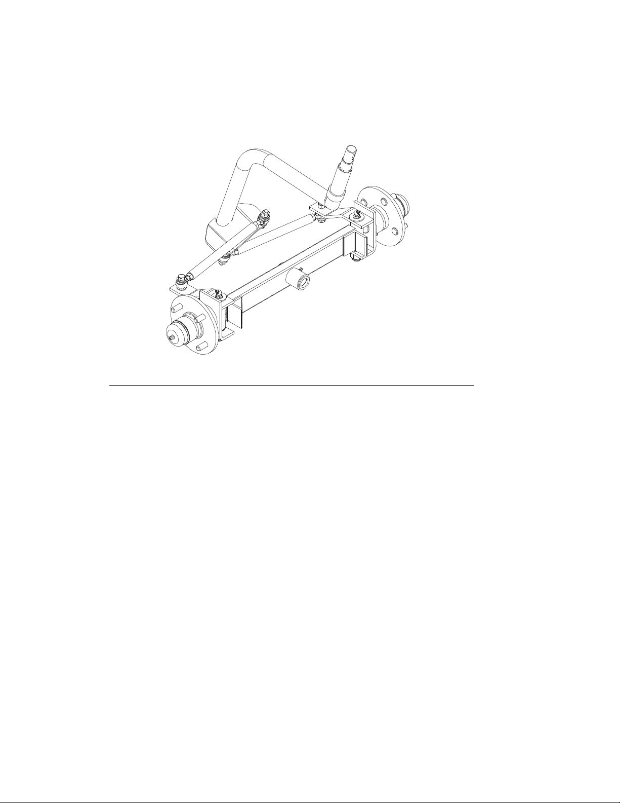
SS5-46 Front Axle and Steering
Replacing the Front Wheel Bearings
To replace worn or damaged wheel bearing, follow the procedure below:
1. Park the vehicle on a level surface.
3. Raise the front of the vehicle and support it with jack stands.
4. Using the appropriate procedure, remove the front wheel from the hub.
5. Using the appropriate procedure, remove the hub from the axle assembly.
6. Remove the oil seal, bearings and bearing races from the hub.
7. Install new bearing races, bearings and oil seals.
8. Install in reverse order using a new cotter pin.
a. Tighten the spindle nut to 30 ft-lbs and then back off one flat and install
the new cotter pin
9. Inject grease into the wheel using a grease gun on the hubs grease fitting.
10. Lower the vehicle and test drive.
3-28
Page 53

Removing the Front Axle Assembly
To remove and install the front axle assembly, follow the procedure below:
1. Park the vehicle on a level surface.
2. Raise the front of the vehicle and support it with jack stands.
3. Reomve both front wheels.
4. Remove the left and right rod ends from the steering knuckles.
5. Remove the front axle pivot pin nut and remove the front axle assembly from
the frame.
6. Install in reverse order.
7. Lower the vehicle and test drive.
Aligning the Front Wheels
To adjust the front wheel toe-in, follow the procedure below:
1. Park the vehicle on a level surface.
2. Turn the front wheels so that they are in the straight ahead position.
3. Measure the distance between the centers at the front of the tires.
4. Measure the distance between the centers at the front of the tires.
5. Adjust the tie rods so that the distance is the same at the front and rear of
the tires.
6. Test drive.
Replace the King Pins or Bushings
To replace the king pins or bushings, follow the procedure below:
1. Park the vehicle on a level surface.
2. Raise the front of the vehicle and support it with jack stands.
3. Remove the wheel from the front axle.
4. Remove the king pin and tie the steering knuckle out of the way..
5. Drive the king pin bushings out from the axle end.
6. Press the new bushings into the axle end.
7. Install the king pin and wheel.
8. Lower the vehicle and test drive.
3-29
Page 54
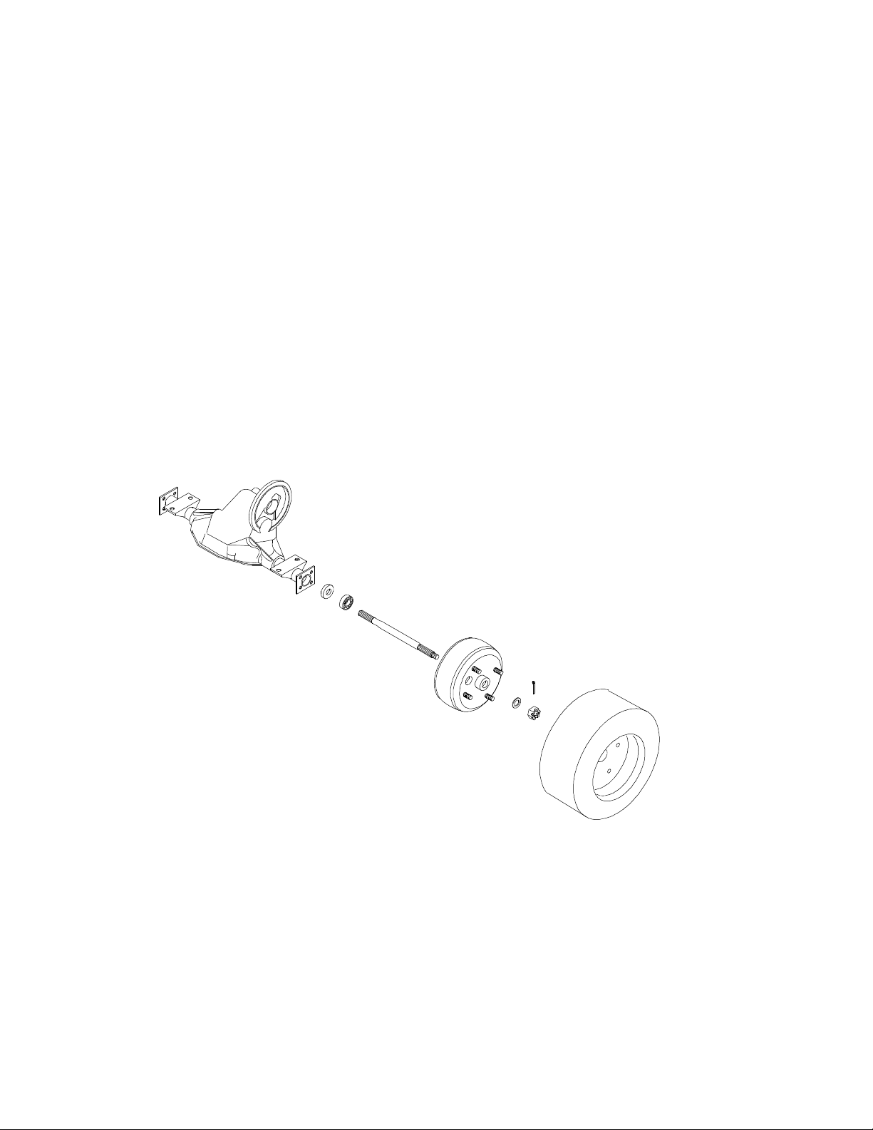
SECTION 3
Rear Axle and Drive Assembly
In this section, we will cover how to install, remove, and service the rear axle and
drive assemblies.
SS5-36, SS5-46 and MX-600
3-30
Page 55
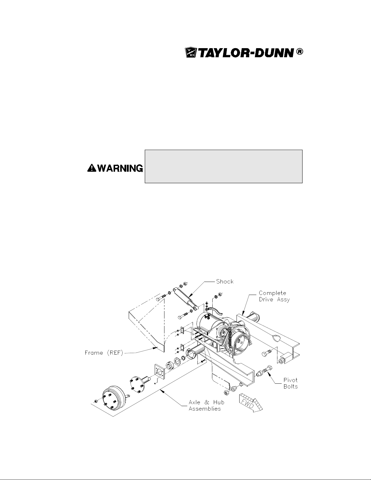
Removing the SS5-34 Rear End Assembly
Here, we are referring to the complete assembly including wheels, axle, housing, drive, and
drive motor. In order to remove this complete assembly from the vehicle, use the following
procedure:
1. Park the vehicle on a clean level surface.
2. Disconnect the batteries.
3. Lift the front of the vehicle and place blocks under the frame.
Always use a lifting strap, hoist, and jack stands of adequate
capacity to lift and support the vehicle. Failure to use lifting and
supporting devices of rated load capacity to support the vehicle
may result in serious injury and property damage.
4. Lower the front of the vehicle onto jack stands.
5. Raise the deck board and disconnect the motor wires.
6. From under the vehicle, remove the brake linkage from the brake lever.
7. Remove the shock from its lower mount.
8. Remove the swing arm pivot bolts.
9. Raise the rear of the vehicle and remove the rear end assembly from the
vehicle.
10. Install in reverse order.
Complete SS5-34 Drive and Rear End Assembly
3-31
Page 56
SECTION 3
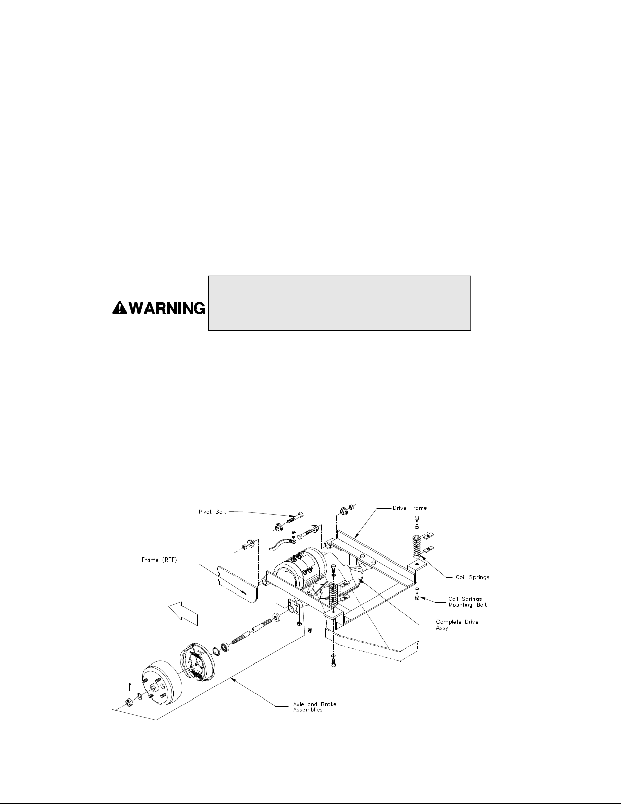
Removing the SS5-36 and SS5-46 Rear End Assembly
Here, we are referring to the complete assembly including wheels, axle, housing, drive, and
drive motor. In order to remove this complete assembly from the vehicle, use the following
procedure:
1. Park the vehicle on a clean level surface.
2. Disconnect the batteries.
3. Lift the front of the vehicle and place blocks under the frame.
4. Lower the front of the vehicle onto jack stands.
Always use a lifting strap, hoist, and jack stands of adequate
capacity to lift and support the vehicle. Failure to use lifting and
supporting devices of rated load capacity to support the vehicle
may result in serious injury and property damage.
5. Support the rear end assembly with a jack and jack stands.
6. Remove the bolts mounting the rear coil springs to the drive frame and
lower the entire frame and rear end assembly.
7. Raise the rear of the vehicle and support it with jack stands.
8. Disconnect the wires from the motor.
9. Disconnect the brake cables.
9. Remove the bolts from the rear end mounting brackets holding the rear end
assembly to the drive frame.
10. Remove the rear end assembly from the vehicle.
11. Install in reverse order.
Complete SS5-36/SS5-46 Drive and Rear End Assembly
3-32
Page 57
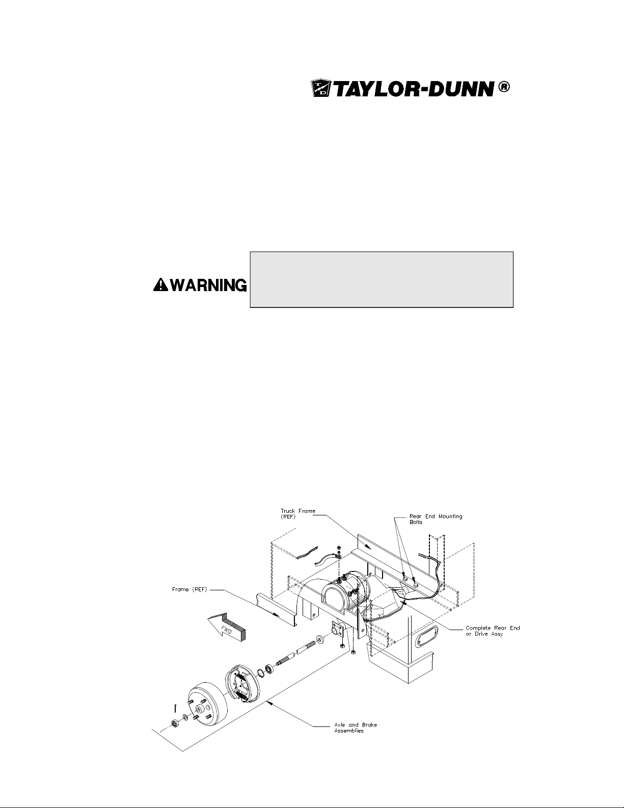
Removing the MX-600 Rear End Assembly
Here, we are referring to the complete assembly including wheels, axle, housing,
drive, and drive motor. In order to remove this complete assembly from the vehicle,
use the following procedure:
1. Park the vehicle on a clean level surface.
2. Dissconnect the batteries
Always use a lifting strap, hoist and jack stands of adequate
capacity to lift and support the vehicle. Failure to use lifting and
supporting devices of rated load capacity to support the vehicle
may result in serious injury and property damage.
3. Lift the front of the vehicle and place blocks under the frame.
4. Lower the front of the vehicle onto jack stands.
5. Raise the rear of the vehicle and support it with jack stands.
NOTE: You may want to remove the tires in order to make it easier to
remove the mounting bolts from the frame.
6. Place another set of jack stands under the drive assembly, and remove
the bolts mounting the drive assembly to the frame.
7. Lower the entire rear end assembly.
8. Disconnect the brake cables.
9. Disconnect the wires from the motor
10. Remove the rear end assembly from under the vehicle.
10. Install in reverse order.
Complete MX-600 Drive and Rear End Assembly
3-33
Page 58

SECTION 3
Differential and Rear Axle
The differential and rear axle assemblies are slightly different between the SS5-34 and
the SS5-36/5-46 and MX-600. For this reason, we have divided this section into two
separate sub sections. The first is for the SS5-34 and the second for the SS5-36, SS546 and MX-600.
The SS5-34 has a belt driven differential, while the SS5-36, SS5-46 and MX-600 are
both direct drive, helical gear driven differentials.
In these sections, we will cover how to disassemble and service these differential and
rear axle assemblies. The belt adjustments for the belt drive system will be included.
To properly service the differential, it will have to be removed. At this point, we are
assuming that the entire assembly has been removed from the vehicle and has been
placed on a clean, level work area or on a stand, designed to hold such an assembly.
An exception to this is when the axles need to be serviced. Then, the entire rear end
assembly does not need to be removed. However, for simplicity, all of the following
instructions have been written as if the rear end assembly has been removed from the
vehicle.
3-34
Page 59
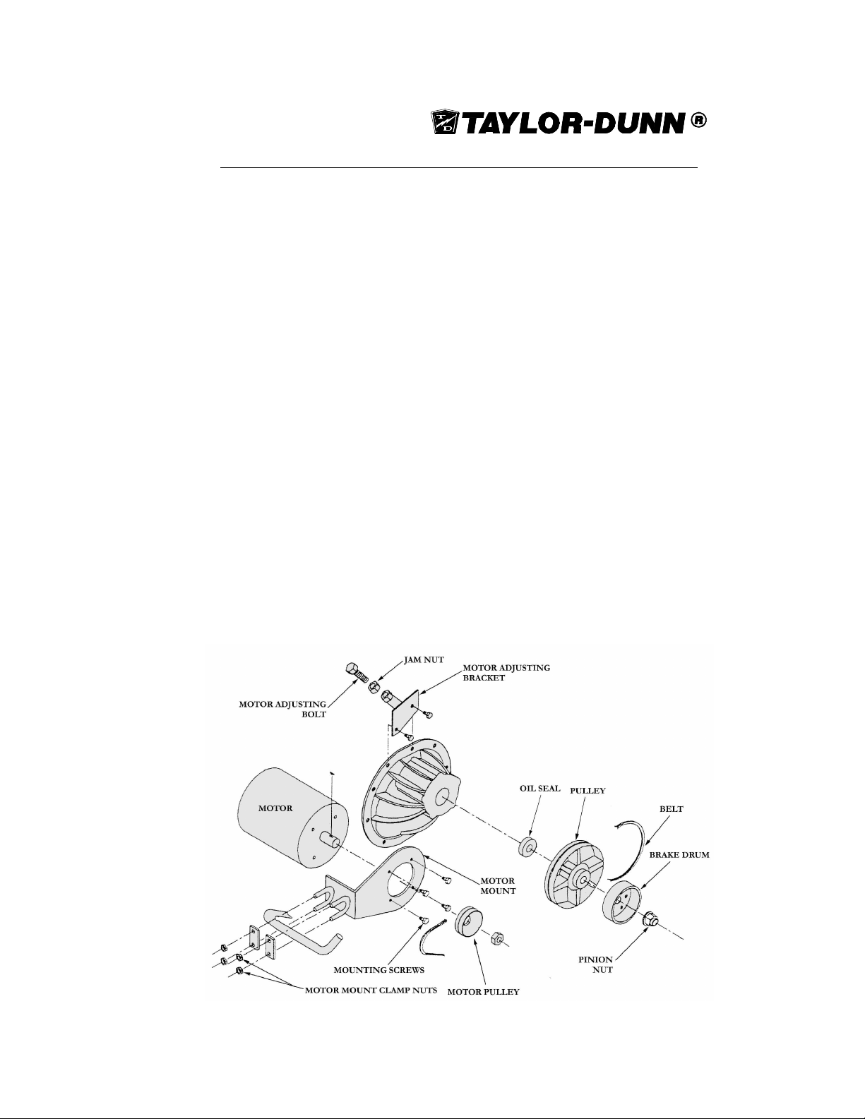
SS5-34 Drive Service
To properly service this assembly, it will have to be removed. At this point, we are
assuming that the entire assembly has been removed from the vehicle and has been
placed on a clean, level work area or on a stand designed to hold such an assembly.
Disassembly of The Belt Drive Assembly
1. Disconnet the batteries.
2. Remove the brake.
3. Loosen the motor mount clamp nuts and the Belt adjusting bolt
locknut.
4. Turn the Belt adjusting bolt until the belts can be removed without
prying or forcing them off.
5. Remove the belts.
6. Remove the motor by removing the motor mount clamp nuts.
7. Remove the pulley from the pinion shaft.
8. Inspect the seal in the pinion bearing retainer. Replace it if it is wornor
damaged.
9. Reassemble in reverse order and adjust the belt tension and the
pulley alignment using the appropriate procedures.
Belt Drive Disassembly
3-35
Page 60
SECTION 3
SS5-34 Removing and Servicing the Rear Axle
This procedure does not require that the rear end or drive assembly be removed in
order to complete. However, if the rear end assembly is removed from the vehicle,
you may skip procedure #1.
1. Raise and support the rear of the vehicle.
Always use a lifting strap, hoist and jack stands of adequate
capacity to lift and support the vehicle. Failure to use lifting and
supporting devices of rated load capacity to support the vehicle
may result in serious injury and property damage.
2. Remove the tire and wheel assembly.
3. Remove the four bolts attached to the axle retaining plate.
4. Pull the axle out of housing.
5. Remove the bearing gasket.
6. Inspect all bearings for roughness or play. Replace the bearings as
needed.
If the bearings are removed from the axle, the axle retainer
and bearings must be replaced with new ones. Failure to
replace these parts could result in the axle coming out of the
vehicle while driving.
7. Inspect the axle for metal fatigue.
8. Install a new rear axle in reverse order.
3-36
Page 61
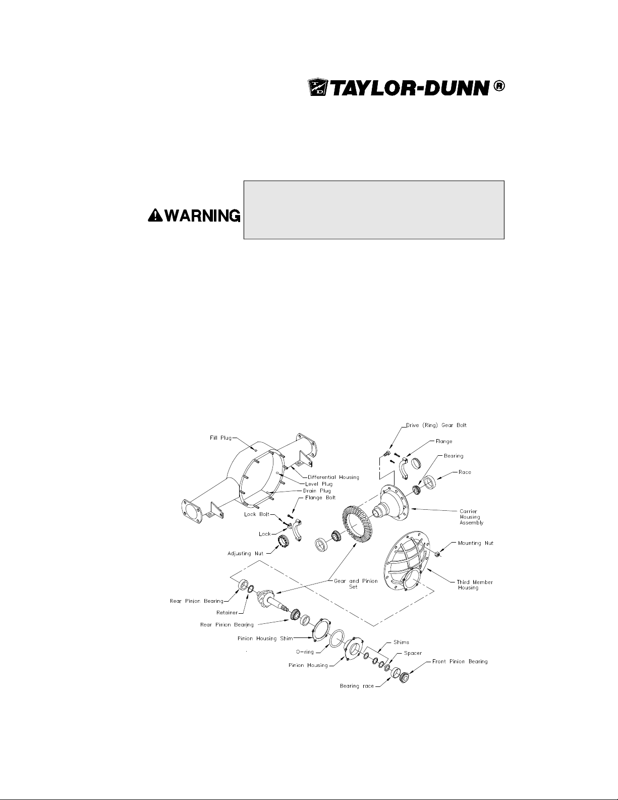
SS5-34 Differential Service and Repair
1. Raise the drive wheels and support the vehicle with jack stands.
Always use a lifting strap, hoist and jack stands of adequate
capacity to lift and support the vehicle. Failure to use lifting and
supporting devices of rated load capacity to support the vehicle
may result in serious injury and property damage.
2. Drain the oil from the drive.
3. Remove the belt drive assemblies.
4. Remove the rear wheels.
5. Slide the axles out from the drive housing.
6. Remove the third member mounting nuts and third member from
the housing.
7. Mark the carrier bearing flanges to insure that they can be installed in
the same orientation during reassembly.
8. Remove the carrier bearing flanges and the carrier assembly from
the housing.
Differential Assembly for the SS5-34
3-37
Page 62

SECTION 3
8. Remove the pinion housing assembly from the third member.
NOTE: Do not lose the shims!
9. Replace bearings, bearing races, and gears as needed.
10. Reassemble in reverse order and follow the instructions in Adjusting
Backlash and Reshimming the Pinion Bearing
a. Pre-lube all bearings and gears during reassembly.
b. Cross tighten ring gear bolts to 72 ft.-lbs.
c. If pinion bearing or gears are replaced, the drive must be
reshimmed.
d. Use new seals.
Adjusting Backlash
1. Install the correctly shimmed pinion gear and pinion gear housing.
2. Temporarily install the drive sprocket and brake drum. Torque the
pinion nut to 175ft.-lbs.
3. Tighten the carrier bearing cap bolts to 15 ft.-lbs.
4. Position the carrier assembly against the pinion gear. While rotating
the carrier, turn the adjusting nuts to contact the carrier bearings.
5. Loosen the adjusting nut on the toothed side of the ring gear.
6. Tighten the other nut so that there is no gear backlash, but not so
tight to cause binding.
7. Tighten the adjusting nut on the toothed side of the ring gear so that
there is .008 to .012 backlash.
8. Tighten the carrier bearing cap bolts to 40-55 ft.-lbs.
Reshiming the Pinion Bearing
1. Remove the pinion housing from the third member.
2. Install the drive gear and brake drum (or equivalent spacer) on to
the pinion shaft and tighten to 175ft.-lbs.
3. Check the torque required to rotate the pinion shaft. Torque spec is 7 to
10 in-lbs.
NOTE: Do not rotate bearings when dry. They must have a
lubricant or they will be damaged.
4. Add or remove shims as necessary to obtain the correct torque.
3-38
Page 63

Selecting Pinion Housing Shims
The pinion housing shims are available in thickness from 0.005” to 0.021”, in increments
of 0.001”, to correctly position the pinion gear. However, the standard shim thickness is
0.015” thick.
The following numbering system is used on pinions to indicate the amount you must
add or subtract from the standard shim in order to correctly position the pinion gear.
Locate the number on the flat surface on the small shaft at the end of the pinion gear.
Match the number with the shim required.
Pinon Numbering System
If the Number is Add Shim(s) as Follows
+0 No Adjustment
+1 Add .001 Shim
+2 Add .002 Shim
+3 Add .003 Shim
+4 Add .004 Shim
+5 Add .005 Shim
-1 Subtract .001 Shim
-2 Subtract .002 Shim
-3 Subtract .003 Shim
-4 Subtract .004 Shim
-5 Subtract .005 Shim
3-39
Page 64
SECTION 3
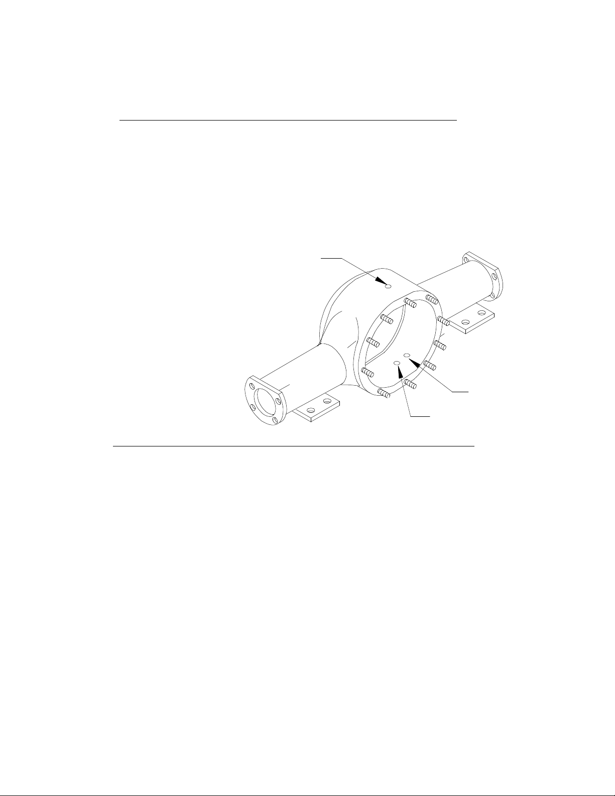
Changing the Differential Oil
1. Place a 3 quart or larger drain pan under the drive.
2. Remove the differential drain plugs.
3. Replace the drain plugs and remove the differential fill and level
plugs.
4. Install oil into the differential through the filler hole until the oil
starts to come out of the level hole (approximately 2 quarts).
5. Install the level plug.
6. Install the remaining plugs.
Fill
Motor Removal
In order to remove the motor from the drive assembly, use the following procedure:
1. Park the vehicle on a level surface and block the wheels to prevent
movement, then disconnect the batteries.
2. Remove the deck board and place it out of the way.
3. Disconnect the batteries.
4. Mark the wire leads on the motor to insure their proper location
when reinstalling the motor.
5. Remove the wire leads from the motor and loosen the motor mount clamp.
6. Loosen the drive belt adjusting bolt lock nut and turn the adjusting bolt
until the belts can be easily removed.
7. Remove the drive belts from the motor pulley.
8. Remove the four motor mounting bolts.
9. Remove the motor assembly from the vehicle.
10. Install in reverse order, adjust the drive belts
Level
Drain
3-40
Page 65
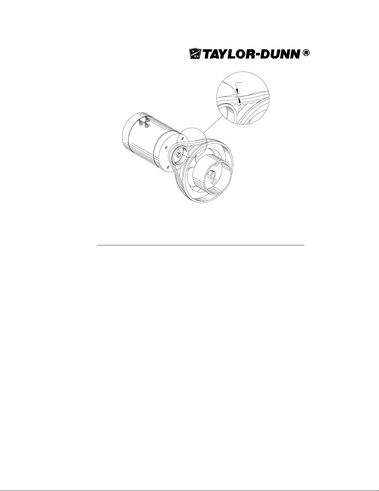
1/4"(.250)
Belt Deflection of 1/4" (.250")
Adjusting Belt Tension
Whenever the belts are removed from the pulleys or as the belts become worn, the
belt tension must be readjusted. In order to adjust the belt tension, follow these
procedures:
1. Check the alignment of the pulleys. The face of the pulleys should be
in line with each other.
2. Loosen the lock nut on the belt adjusting bolt.
3. Turn the adjusting bolt in or out as needed to tension the belts
properly.
NOTE: There should be a 1/4” deflection in the belts at the
mid point between the two pulleys.
4. Check the deflection in the belts, then rotate the pulleys one full
turn. Check the deflection again.
5. If the deflection is correct, tighten the lock nut on the motor adjusting
bolt. If the deflection is not correct, repeat steps 2 through 4 again.
3-41
Page 66
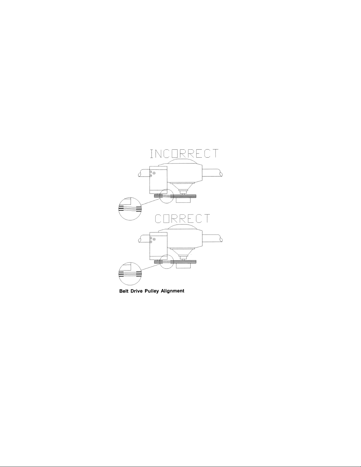
SECTION 3
Aligning Pulleys
To align the pulleys, use the following procedure:
1. Loosen the motor mount clamp nuts and move the motor either
forward or backward until the two pulley faces are in line with
each other.
2. Tighten the motor mount clamp nuts and check the belt deflection.
Adjust the belts as needed.
3-42
Page 67
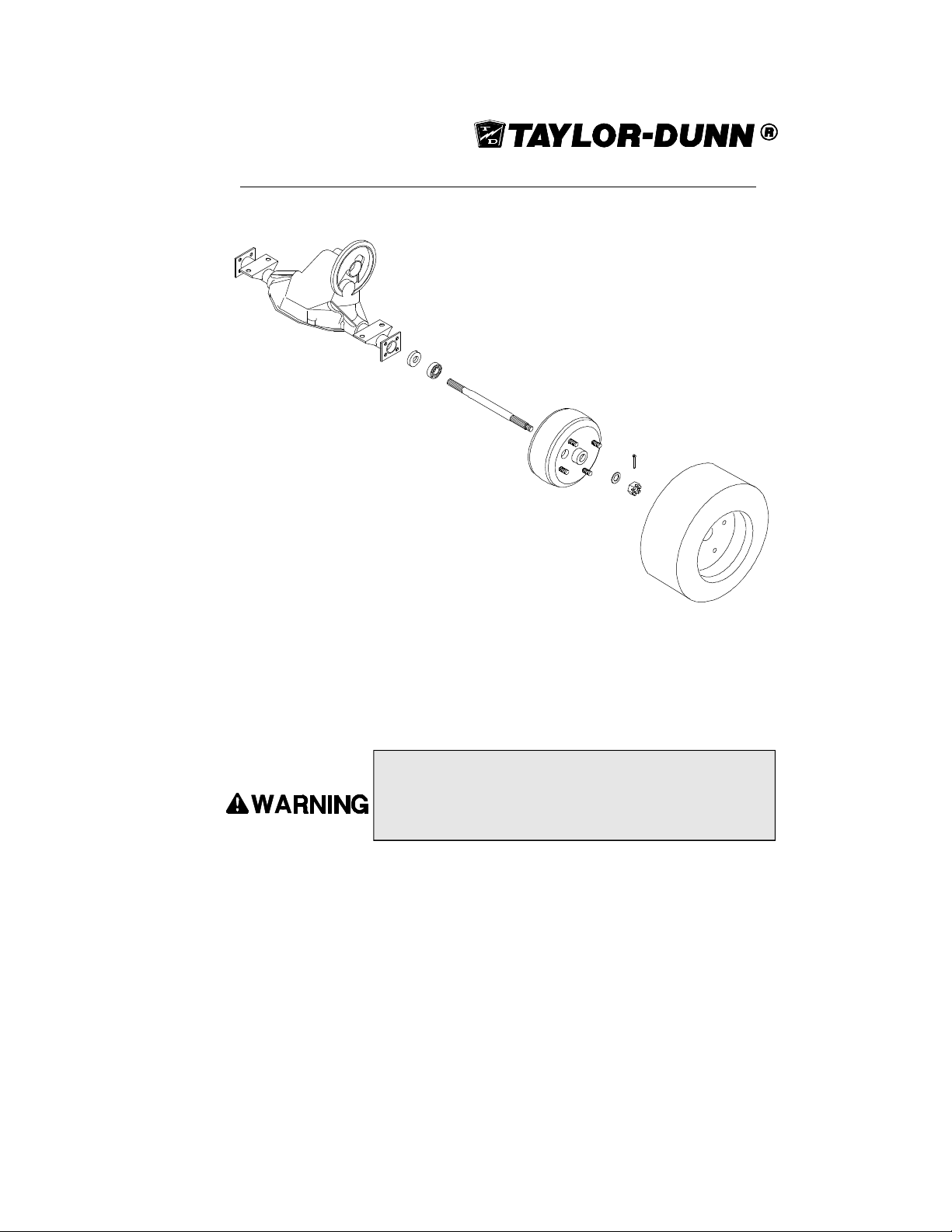
SS5-36, SS5-46 and MX-600 Drive Service
To properly service this assembly, it will have to be
removed from the vehicle. At this point, we are
assuming that the entire assembly has been
removed from the vehicle and has been
placed on a clean, level work area
SS5-36, SS5-46 and MX-600 Drive Assembly
SS5-36/SS5-46/MX-600 Removing and Servicing the Rear Axle
This specific procedure does not require that the rear end or drive assembly be
removed in order to complete. Refer to the illustration on the following page.
1. Raise and support the rear of the vehicle with a hoist or other suitable
lifting device.
Always use a lifting strap, hoist and jack stands of adequate
capacity to lift and support the vehicle. Failure to use lifting and
supporting devices of rated load capacity to support the vehicle
may result in serious injury and property damage.
2. Remove the tire and wheel assembly.
3. Remove the four bolts attached to the axle retaining plate.
4. Pull the axle out of the housing.
5. Remove the bearing gasket.
6. Inspect all bearings for roughness or play. Replace the bearings as
needed.
7. Inspect the axle for metal fatigue.
8. Install a new rear axle in reverse order.
3-43
Page 68
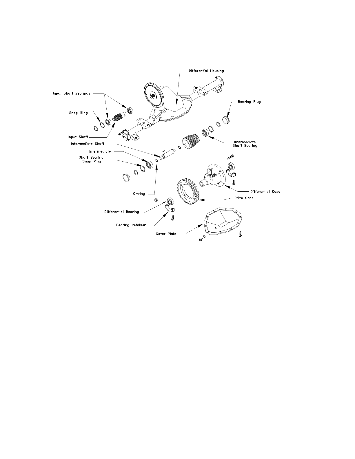
SECTION 3
Exploded View of SS5-36, SS5-46 and MX-600 Differential Assembly
Servicing the Differential
At this point, we are assuming that the complete drive assembly and differential has
been removed from the vehicle and has been properly placed in a safe work area.
To service the differential use the following procedure:
1. Drain the oil from the differential into the appropriate receptacle.
2. Remove the axle shafts from the differential.
3. Remove the cover plate from the differential and let the remaining
oil drain from the housing.
NOTE: Do not damage the housing sealing surface or deform
the cover plate.
4. Dispose of the old oil properly.
5. Remove the bearing cap screws and bearing caps.
NOTE: Bearing caps are marked for identification during
reassembly. Make sure they are put back in their original
position.
3-44
Page 69

6. Remove the differential case assembly from the housing.
7. Remove the differential bearings from each side of the case.
8. Remove the drive gear from the case.
9. Punch or drill a 1/8” hole in the center of each bearing bore plug.
10. Insert a suitably sized sheet metal screw into the hole until the bore
plug is forced out of the bearing bore.
11. Remove the snap ring from each bearing bore.
12. Drive the intermediate shaft from the flange side of the housing.
NOTE: Use a brass drift pin to drive the shaft from the
housing.
13. Remove the intermediate bearings from the housing.
14. Remove the O-Rings from the intermediate shaft.
15. Remove the snap rings from the input shaft bore.
16. Pull the input shaft assembly from the housing.
17. Remove the bearings from the input shaft.
18. Remove the O-Rings from the outer input bearing bore and both
intermediate bearing bores.
19. Inspect all parts for signs of wear or damage.
NOTE: Bearing, seal, and gear surfaces should be inspected
for pitting, wear, overheating, or scoring. Replace these parts
as needed.
20. Thoroughly clean all parts.
21. Lubricate all parts with SAE 30 motor oil.
22. Press inner and outer bearings on to the input shaft.
23. Install the input shaft.
24. Install the outer snap rings and O-Rings onto the intermediate shaft.
25. Assemble the intermediate shaft and gear assembly through the
bottom opening of the housing.
NOTE: The Small end of intermediate shaft and gear assembly
must be tilted toward the bottom opening, until the bearing
trunnion visually engages the intermediate bores.
26. Align both the bearing trunnions with intermediate bores.
27. Insert the flange side bearing into the opening.
3-45
Page 70

SECTION 3
28. After the flange side bearing is seated install the snap ring.
29. Repeat procedures for opposite side.
30. Align the final drive gear mounting holes with the differential case,
31. Press the differential bearings onto the differential case.
32. Position the drive housing with the opening facing up and install the
33. Install the differential bearing caps
34. Install the bearing cap screws and torque them to 35-45 ft. lbs.
35. Install the cover plate and torque the cover plate screw to 18-28 ft.
36. Install new intermediate bore plugs into both sides of the housing.
install the four bolts through the differential case, and secure the
drive gear in place by tightening the nuts.
NOTE: The bolts should be installed from the flange side of
the differential case.
differential assembly.
NOTE: Remember that the bearing caps are marked. Be sure
to reinstall the bearing caps back into their original position.
lbs.
NOTE: Bore plugs should be firmly against the snap rings
when fully seated.
37. Fill differential housing with 10 ounces of SAE 30 motor oil.
3-46
Page 71
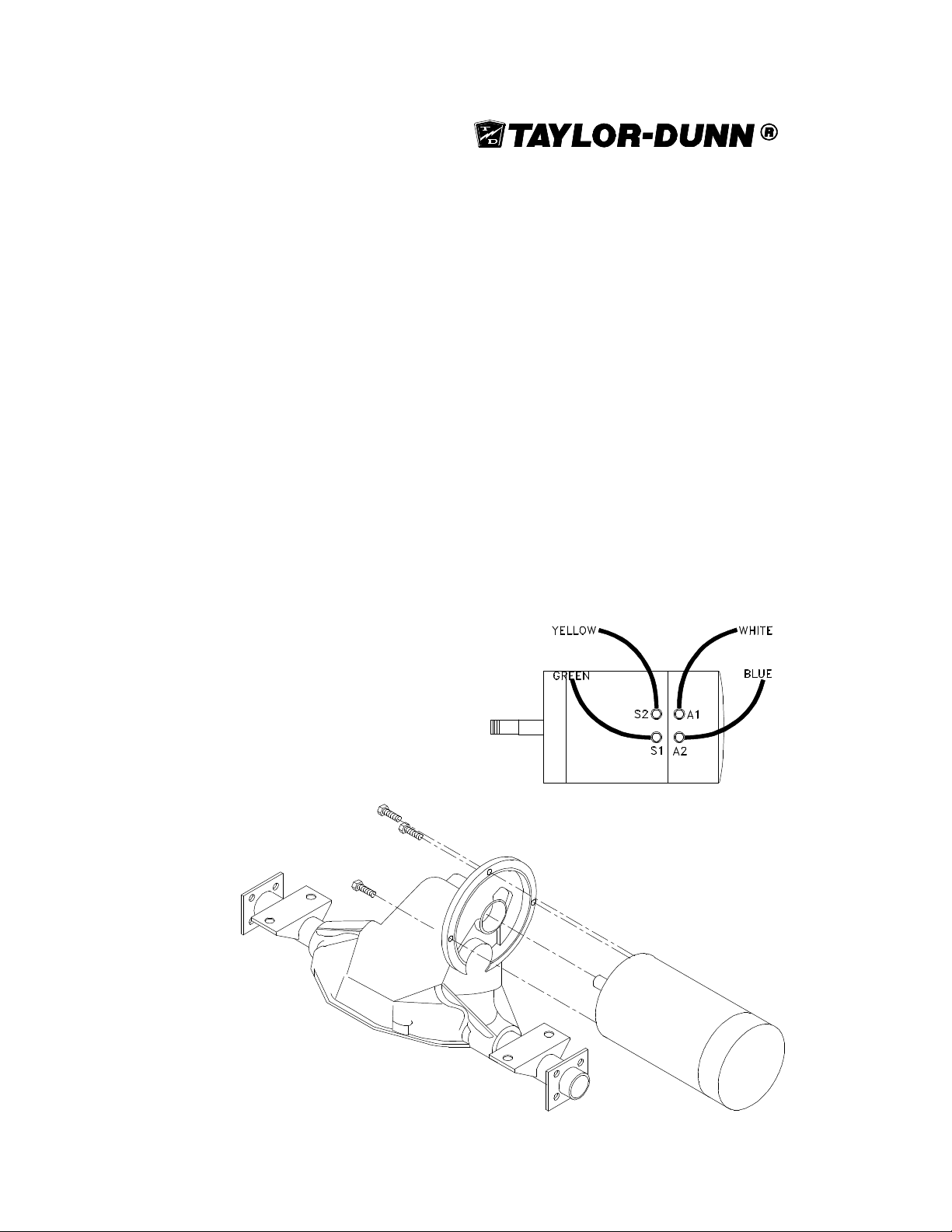
Motor
SS5-36/SS5-46/MX-600 Motor Removal
To remove the motor from the differential use the following procedure:
NOTE: IF YOU ARE SER VICING A MX-600 THE DIFFERENTIAL AND REAR END ASSEMBLY MUST BE
REMOVED FROM THE VEHICLE TO COMPLETE THIS
TASK. IF YOU ARE SER VICING A SS5-36, YOU MA Y
SIMPL Y REMOVE THE DECK BOARD TO GAIN
ACCESS TO THE MOTOR.
1. Disconnect the batteries.
2. Support the motor.
3. Label the wires connected to the motor to insure that they are
returned to their proper location.
4. Remove the wires from the motor.
5. Remove the motor mounting bolts from the drive.
6. Pull the motor away from the drive and set on a clean, level surface.
7. Install the new motor or reassemble in reverse order.
Wire Connections on Motor
Motor Mounted on Assembled SS5-36, SS5-46 and MX-600 Differential
3-47
Page 72

SECTION 3
SS5-34 Motor Removal
1. Park the vehicle on a level surface and block the wheels to prevent
movement. Disconnect the batteries.
2. Remove the deck board and place it out of the way.
3. Mark the wire leads on the motor to insure their proper location
when reinstalling the motor.
4. Remove the wire leads from the motor and loosen the motor mount
clamp.
5. Loosen the motor adjusting bolt lock nut and turn the adjusting bolt
until the belts can be easily removed.
6. Remove the belts.
7. Remove the four motor mounting bolts from the face of the motor.
8. Remove the motor assembly from the vehicle.
9. Install in reverse order and adjust the belts using the appropriate
procedure.
Brushes
The motor brushes must be checked regularly for wear. Use the following procedure
to check the brushes in the motor for wear:
1. Remove the motor from the drive assembly.
2. There is a small inspection hole above each of the four brushes.
Insert a .035” rod or paper clip into the inspection hole until it
contacts the top of the brush. Mark the rod and measure how far it
was inserted into the motor.
3. If the rod travels into the hole 1.5” or more, then the brushes must be
replaced. Inspect all four brushes.
NOTE: We recommend that all the brushes be replaced at
the same time.
3-48
Page 73
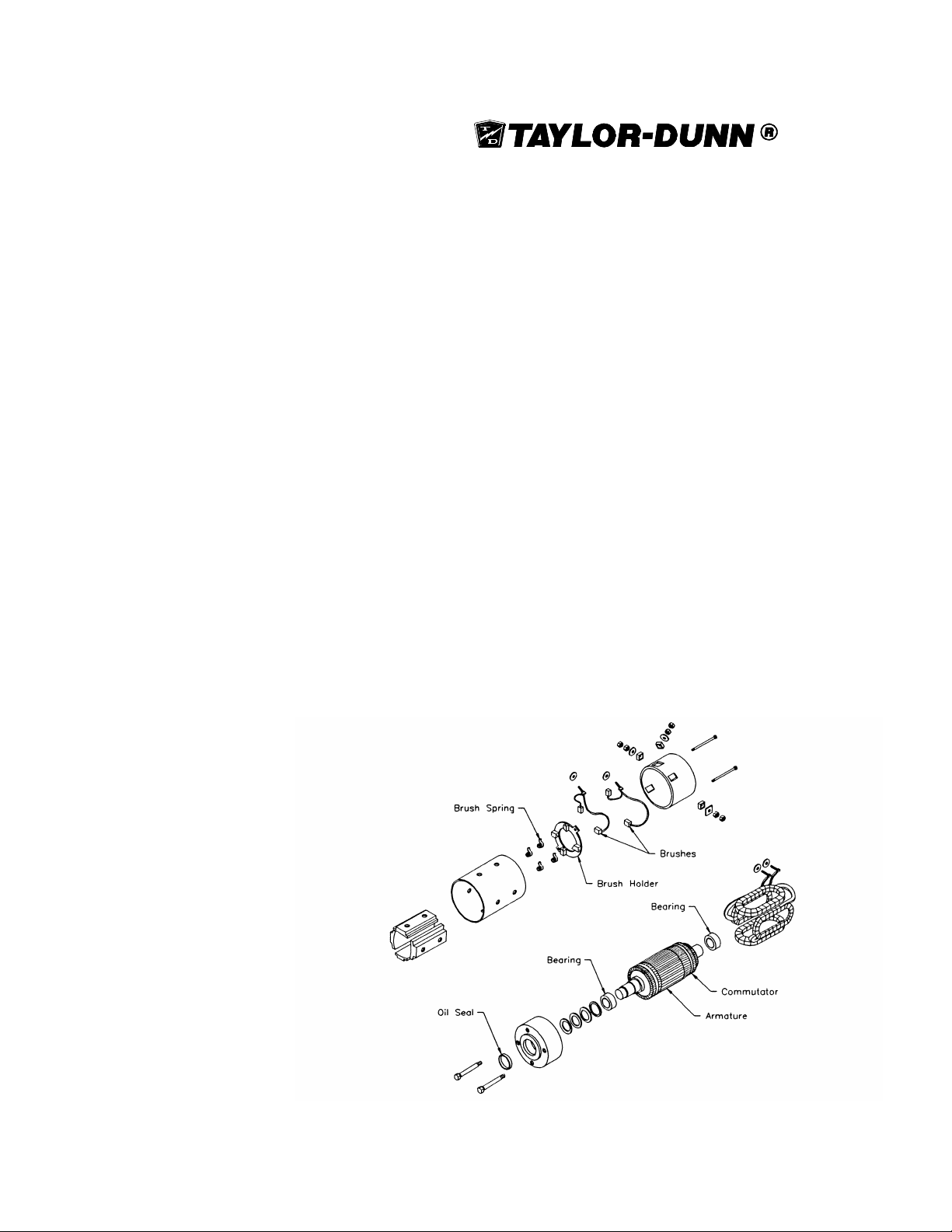
Installing New Brushes
In order to install new brushes in the motor use the following procedure:
1. Remove the motor from the rear end assembly.
2. Remove the motor cover revealing the brush holder and brushes.
3. Disassemble the brush studs from the cover.
4. Remove the old brushes and install the new ones.
5. Inspect the commutator for wear.
6. Replace the motor cover and reinstall the motor on the rear end
assembly.
Motor Disassembly
1. Remove the motor.
2. Disassemble the motor.
NOTE: Mark the housing to insure proper alignment when
reassembling.
3. Inspect the armature and commutator.
4. If the bearings were removed due to wear, install new bearings on
the shaft. (Other wise continue on to step #5.)
5. Reassemble the motor.
6. Install the motor onto the rear end assembly.
Exploded View of Motor for All Models
3-49
Page 74
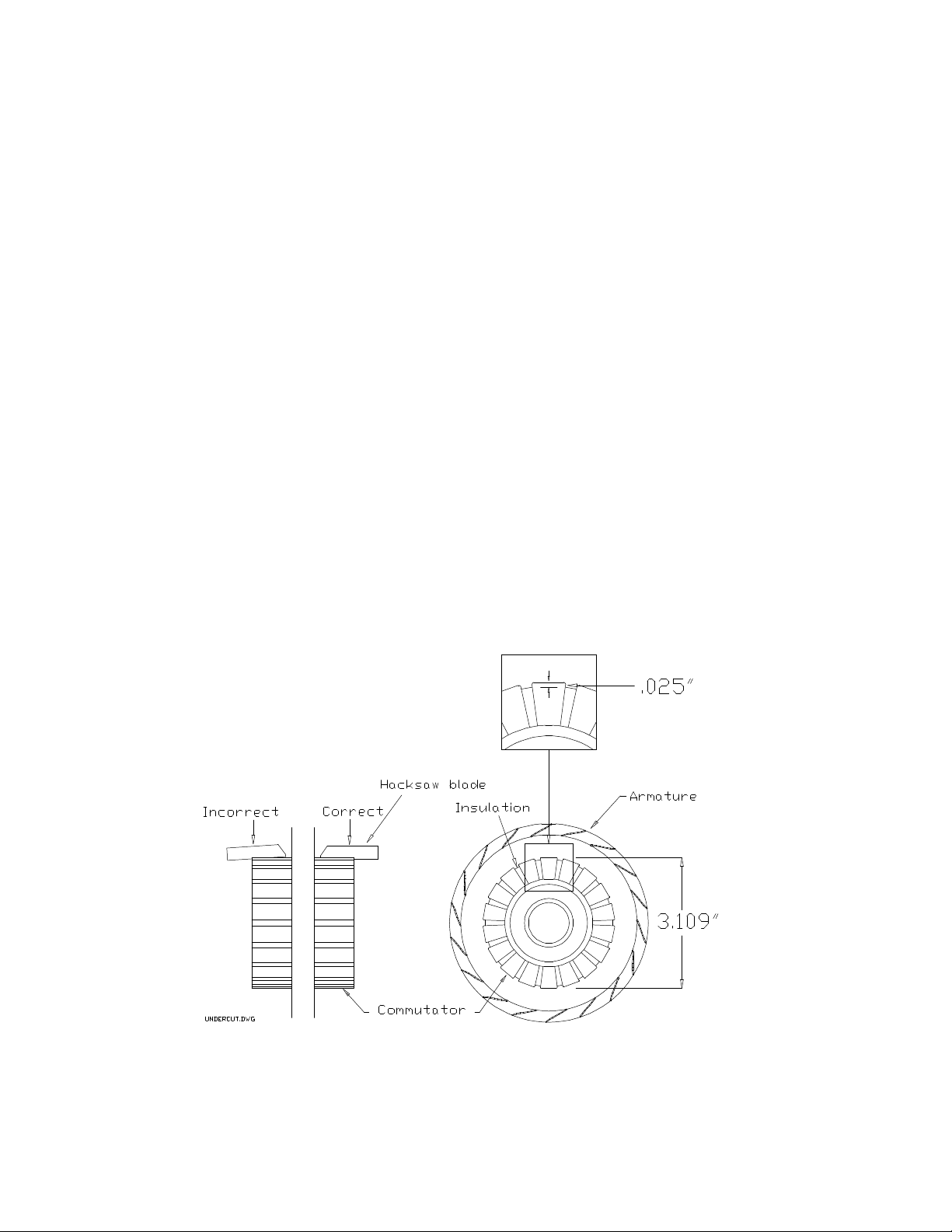
SECTION 3
Inspecting the Armature
1. If any solder has been thrown from the armature the motor must be
replaced.
NOTE: Check the inside of the motor housing around the
commutator for bits of solder.
2. If the commutator is grooved, it must be cut on a lathe.
3. Measure the undercut on the commutator.
a. If less than .025", then the mica must be undercut.
4. Measure the commutator diameter.
a. If less than 3.109", then the armature is worn out and the motor
must be replaced.
5. Spin the bearings by hand.
a. If any vibration or roughness is felt, they must be replaced.
Correct Way to undercut the Commutator and Correct Mica Depth
3-50
Page 75
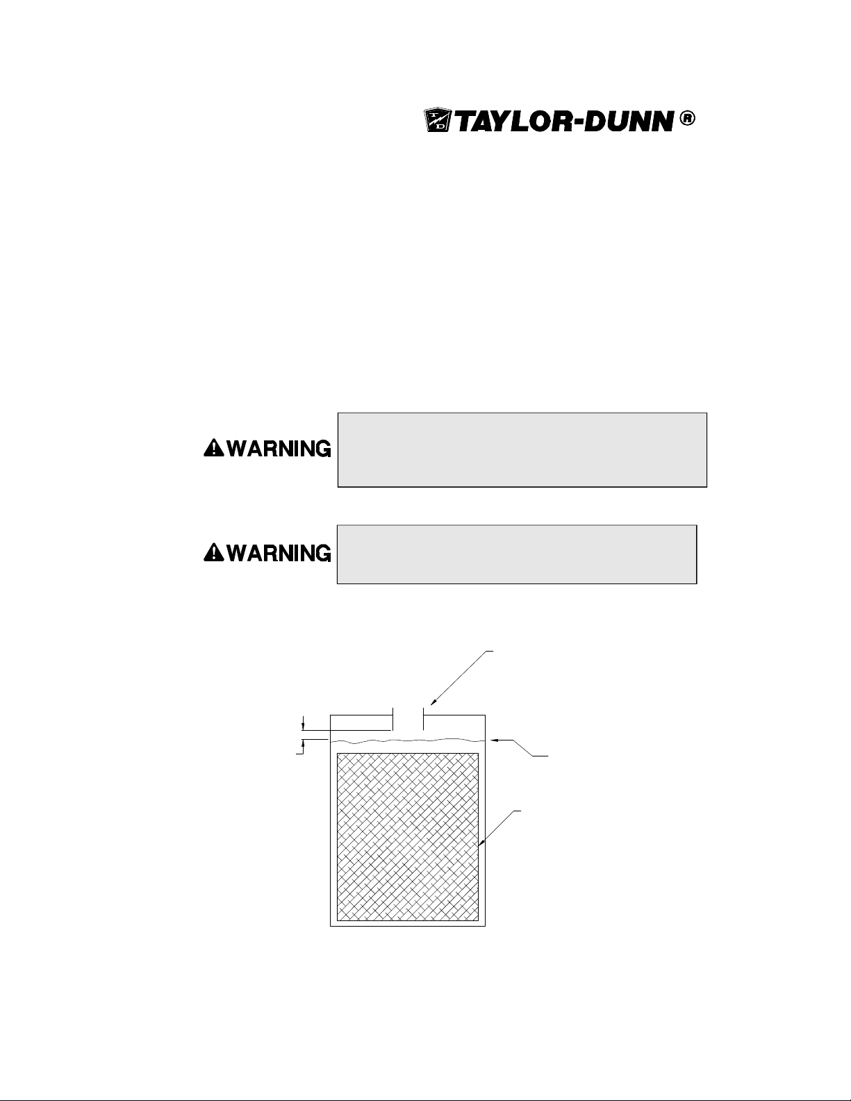
Battery
Cleaning
1. Dry dirt can be readily blown off with low-pressure air or brushed off.
2. Wetness or wet dirt on the covers indicates battery acid. Using a nonmetallic
brush with flexible bristles, wash it off with a strong solution of baking soda
and hot water (1 lb. of soda to gallon of water). Continue until all fizzling
stops, which indicates that the acid has been neutralized. Then rinse
thoroughly with clear water. DO NOT get any of the solution into the battery
cells.
Battery electrolyte is poisonous and dangerous. It contains
sulfuric acid. Avoid contact with skin eyes or clothing. Wear
rubber gloves and safety glasses while servicing batteries. DO
NOT INGEST!
Batteries produce an explosive gas when charging. DO NOT
SMOKE, produce an open flame or spark while checking or
servicing a battery.
1/4"
Filler neck
Max water
level
Plate
(inside battery)
Battery
cutaway
3-51
Page 76
SECTION 3
Servicing the Batteries
1. Check the electrolyte level in all batteries. If low, fill with distilled water up to
the correct level.
Do not overfill the battery. An overfilled battery may leak acid.
2. Clean the battery.
3. Clean the cell posts connectors and battery box with water.
Charging
To charge the batteries do the following:
1. Check the electrolyte level. If low, fill with distilled water up to the correct
level.
Explosive mixtures of Hydrogen gas are present within battery
cells at all times. Do not work with or charge battery in an area
where open flames (including gas furnace or water heater
pilots), sparks, cigarettes, or any other sources of combustion
are present. Always provide ample ventilation in rooms where
batteries are being charged.
2. Park the vehicle in an approved area for charging and plug the charger in.
3. Allow the charger to cycle completely before unplugging.
Battery Storage
The following pointers will help extend the life of the battery when storing your vehicle for
the winter season:
n Clean and check the electrolyte level and charge level of the battery. Do not
store a battery low in electrolyte or in a low state of charge.
n Recharge a battery not in use every 1 to 2 months.
n If possible, store the vehicle in a cool, dry place.
If the batteries are removed from the vehicle, do not place them directly on the ground,
concrete or solid metal surface. It is recommended to store them on a wooden pallet or
equivalent.
3-52
Page 77
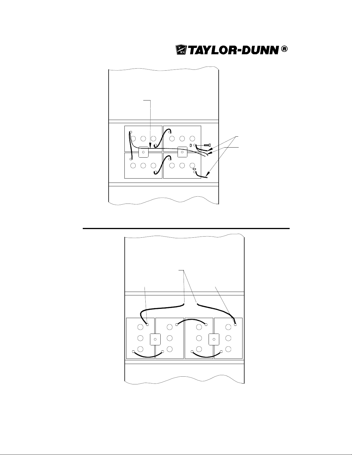
Negative Tap
NEG
NEG
To Control
Panel
Positive Tap
POS
NEG
POS
POS
NEG
REAR OF VEHICLE
Battery Configuration: Shown are the batteries and how they are connected
together for the SS5-34, SS5-36 and SS5-46.
MX-600
TO CONTROL PANEL
12V POSITIVE
TAP
12V NEGATIVE
TAP
POS
NEG
NEG
POS
NEG
POS
NEG
POS
REAR OF VEHICLE
Battery Configuration: Shown are the batteries and how they are connected
together for the MX-600.
3-53
Page 78

TAYLOR -DUNN
Page 79
SECTION 4-Electrical Troubleshooting
Page 80

ELECTRICAL TROUBLESHOOTING
Solenoids
Circuit Breaker
FWD
REV
ISO
PMC Speed Control
Typical Control Panel
Syptoms:
If your vehicle exhibits any of the following symptoms then skip the main troubleshooting
sequence and proceed to
troubleshooting sequence.
• Runs slow in both directions plus high armature and field current in both directions. NOTE:
Armature and field current should be equal.
•
Runs slow in both directions plus high armature current in both directions. NOTE: Field
current will be very low.
•
Runs normal in one direction only plus runs slow or lacks power in the opposite direction
with high armature current in the opposite direction or;
•
Accelerates slowly and exceeds normal speed in the opposite direction with high armature
current only. NOTE: Field current will be very low in the opposite direction.
•
Accelerates slowly and exceeds normal speed in both directions plus high armature current.
NOTE: Field current will be very low.
•
Full speed only.
• Does not run in either direction plus there is noise from motor (hum or whine) with high
field current and low armature current.
•
Jumps into high speed when direction is selected after depressing the accelerator
pedal.Excessive spark when connecting battery
•
Does not run or runs very slow with low motor current and high battery current.
•
Jumps into high speed when direction is selected after depressing the accelerator pedal.
If your vehicle does not exhibits any of the above symptoms then continue with the main
troubleshooting sequence on the following pages.
Special Troubleshooting
in Section 4 at the end of the main
SECTION 4 Main Sequence PAGE 2
Page 81
ELECTRICAL TROUBLESHOOTING
Main Troubleshooting Sequence
Test Equipment Required:
•
Digital multimeter (DMM) with diode test function, FLUKE 79 model used in illustrations.
•
Shunt or clamp-on DC Ammeter to measure up to 400 amps.
•
Test light with a rated voltage equal to or exceeds maximum battery voltage or TaylorDunn test light part number #62-027-00 for systems up to 48 volts.
•
Test harness, Taylor-Dunn #62-027-31. This troubleshooting guide assumes that the
vehicle is wired correctly. It is not intended to diagnose a vehicle that is not wired correctly.
•
These tools are available through your local Taylor-Dunn parts distributor.
IMPORTANT NOTES and INSTRUCTIONS
•
This troubleshooting guide assumes that the vehicle is wired correctly. It is not intended
to diagnose a vehicle that is not wired correctly.
•
This troubleshooting guide is not written to be able to locate a problem if there are multiple
component failures.
•
This troubleshooting guide assumes the batteries are good. Charge and test the batteries
before troubleshooting the control system.
•
DO NOT start in the middle of this troubleshooting guide. Start at the beginning and
complete each test in the order that they are written. Do not skip any test unless instructed
to do so. Once a problem is found, stop testing and repair the indicated problem. When
the repair is completed it is recommended that the control system be retested before
lowering the drive wheels to the ground.
These test procedures must be performed in the order they were
written. If the test result is good, then proceed to the next test or
go to the next section. Failure to do so may result in incorrect test
results.
•
This troubleshooting guide requires the use of a test light rated at the battery voltage of
the truck and the Taylor-Dunn Accelerator Module Test Harness. Troubleshooting CANNOT
be completed without these tools.
SECTION 4 Main Sequence PAGE 3
Page 82
ELECTRICAL TROUBLESHOOTING
Definitions:
•
“MS-1” = The first switch in the accelerator module.
•
“Battery volts” = The voltage at the batteries at the time the test is completed.
•
“Pick up” = Energizing a solenoid or contactor.
•
“F&R” = Forward and Reverse.
•
“ISO” = Isolator.
•
“Battery negative” = Main negative battery post.
•
“Battery positive” = Main positive battery post.
•
“PMC” = Speed control module (black box).
•
“HOT terminal” = The side of a switch or solenoid that is connect to the power source.
•
“COLD terminal” = The side of a switch or solenoid that power is switched to.
DURING ALL TESTS
After any repairs are made, completely retest the vehicle before
lowering the drive wheels to the ground. Failure to retest the vehicle
could result in unexpected movement of the vehicle resulting in injury
or property damage.
The rear drive wheels may rotate during some of the following tests.
Block the front wheels, raise the rear drive wheels off the ground,
and support the vehicle with jack stands. Failure to do so may cause
the vehicle to move and cause property damage and/or serious bodily
injury.
Rotating rear drive wheels are a potential hazard. Keep hands, arms,
legs and loose clothing away from the rear drive wheels while
conducting tests. Failure to do so may cause serious bodily injury.
Disconnect both of the battery leads during any maintenance or
before disconnecting any electrical component or wire. Failure to do
so may cause property damage and/or serious bodily injury.
START:
Read all warnings above before continuing.
If the vehicle runs normal in one direction but does not run in the opposite direction then go to
the
Solenoids
If none of the three solenoids pick up (click) when the accelerator pedal is depressed then go
to the
Forward & Reverse Switch
sequence.
sequence.
SECTION 4 Main Sequence PAGE 4
Page 83
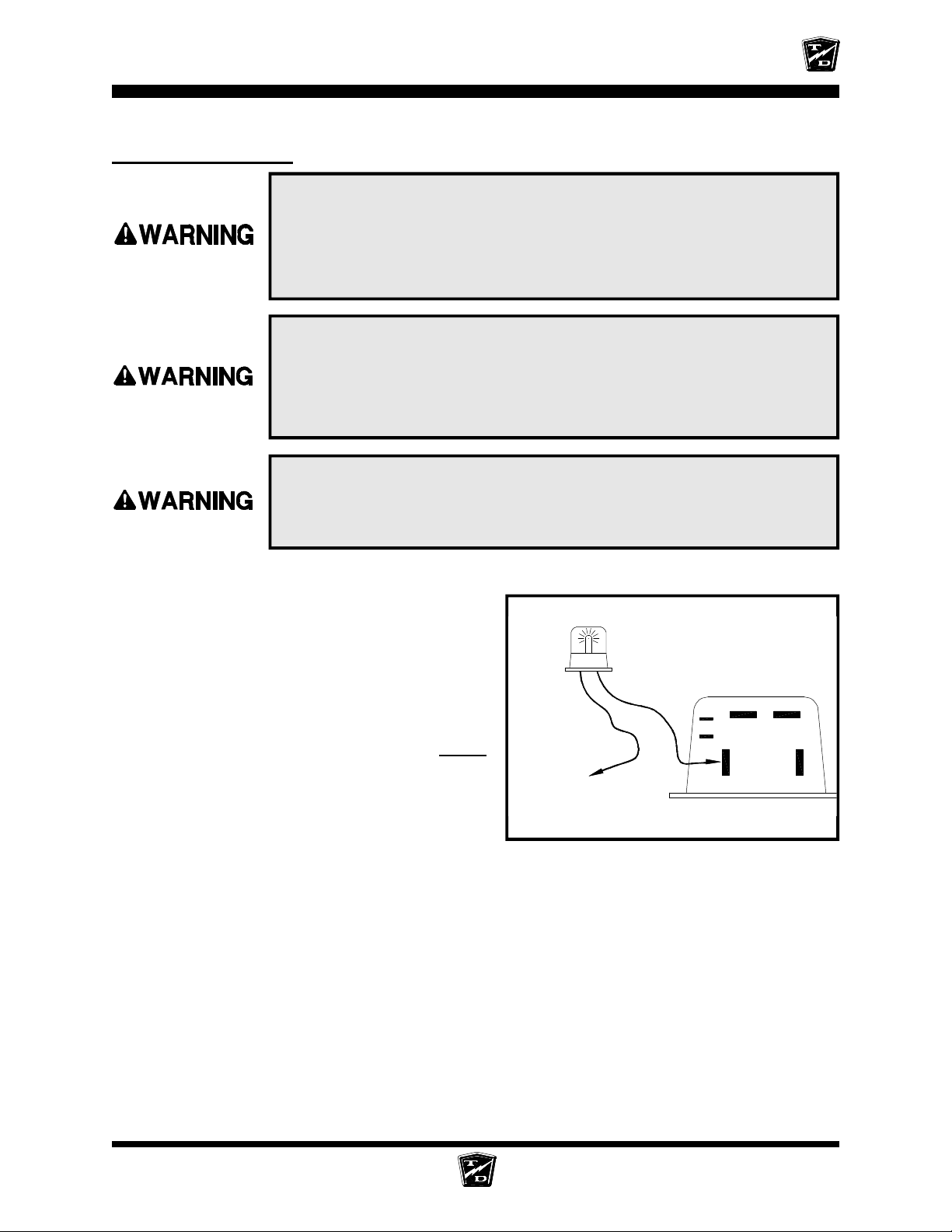
Power Output Test
ELECTRICAL TROUBLESHOOTING
1. Make sure the key-switch is in the “OFF” position, then remove
the key.
2. Place the forward-reverse switch in the center “OFF” position.
3. Set the park brake.
4. Place blocks under the front wheels to prevent vehicle movement.
The rear drive wheels may rotate during some of the following tests.
Block the front wheels, raise the rear drive wheels off the ground,
and support the vehicle with jack stands. Failure to do so may cause
the vehicle to move and cause property damage and/or serious bodily
injury.
Rotating rear drive wheels are a potential hazard. Keep hands, arms,
legs and loose clothing away from the rear drive wheels while
conducting tests. Failure to do so may cause serious bodily injury.
Set the test light voltage to the same voltage as the
battery volts.
Connect the test light from the PMC ‘M-’ Terminal
to battery positive.
Close all interlock switches, turn the Key Switch
ON, and place the F&R Switch in Forward.
Depress the accelerator pedal fully.
•
If the light comes ON then go to the
sequence.
•
If the light does not come ON then continue
with the next test.
Motor
Test Light
Main Battery Positive
Face of Controller
KSI
B-
#2
B+
M-
A2
SECTION 4 Main Sequence PAGE 5
Page 84
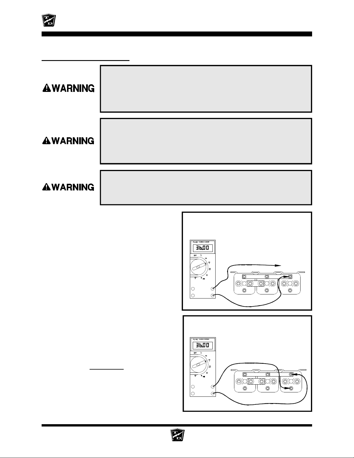
ELECTRICAL TROUBLESHOOTING
Control Wire inputs Test
1. Make sure the key-switch is in the “OFF” position, then remove
the key.
2. Place the forward-reverse switch in the center “OFF” position.
3. Set the park brake.
4. Place blocks under the front wheels to prevent vehicle movement.
The rear drive wheels may rotate during some of the following tests.
Block the front wheels, raise the rear drive wheels off the ground,
and support the vehicle with jack stands. Failure to do so may cause
the vehicle to move and cause property damage and/or serious bodily
injury.
Rotating rear drive wheels are a potential hazard. Keep hands, arms,
legs and loose clothing away from the rear drive wheels while
conducting tests. Failure to do so may cause serious bodily injury.
Connect a voltmeter across the Solenoid
Negative Buss Bar and battery positive.
•
If the voltage is not at battery volts then
check the wiring to battery negative and
the negative circuit breaker. Stop trouble
shooting here and repair the problem.
When the repair is completed,
completely retest the vehicle before
lowering the drive wheels to the ground.
Connect a voltmeter across the ISO solenoid coil
terminals.
Close all interlock switches and turn the
Key Switch ON.
Depress the accelerator pedal to engage
MS-1 only.
• If the voltage is not at battery volts then
go to the
• If the voltage is at battery volts and the
ISO solenoid does not pick up (click) then
the ISO solenoid has failed. Stop trouble
shooting here and repair the problem.
When the repair is completed, completely
retest the vehicle before lowering the
drive wheels to the ground.
Key Switch
sequence.
The voltage shown is for illustration
only. The actual voltage may vary.
Solenoids are shown for reference
only. The type of solenoid in your
truck may look different
+
_
The voltage shown is for illustration
only. The actual voltage may vary.
Solenoids are shown for reference
only. The type of solenoid in your
truck may look different
+
_
FWD
FWD
REV
REV
Main Battery
Positive
ISO
ISO
SECTION 4 Main Sequence PAGE 6
Page 85
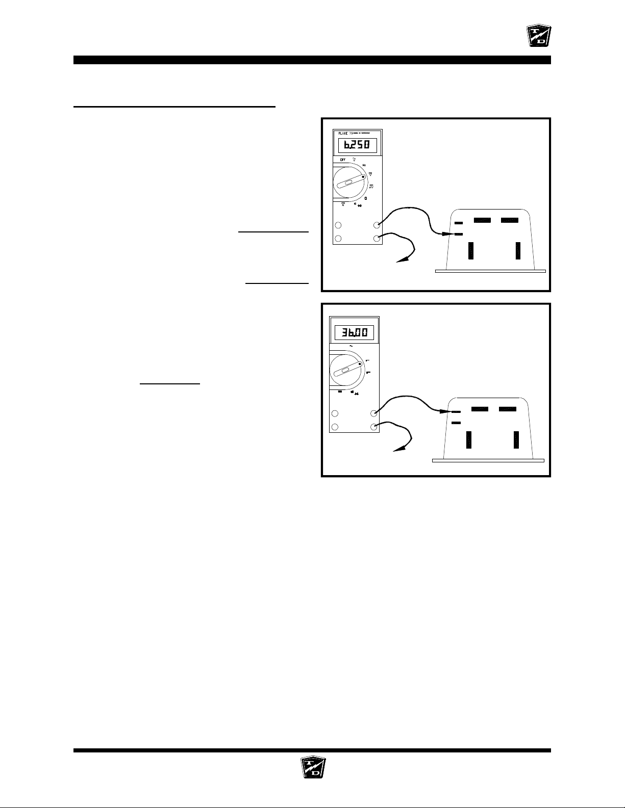
ELECTRICAL TROUBLESHOOTING
Control Wire inputs (continued)
Connect a voltmeter across the PMC #2 terminal
and battery negative.
Close all interlock switches, turn the Key Switch
ON, and place the F&R Switch in Forward.
Depress the accelerator pedal to engage
MS-1 only.
•
If the voltage is not between 6.0 and 6.5
volts then go to the
Accelerator
sequence.
Depress the pedal fully.
•
If the voltage is not between 11.0 and
11.5 volts then go to the
Accelerator
sequence.
Connect voltmeter across the PMC KSI terminal
and battery negative.
With the pedal still fully depressed:
•
If the voltage is not at battery volts then
go to the
•
continue with the next test.
Key Switch
sequence.
If the voltage is at battery volts then
+
_
Main Battery
Negative
SERIES II MULTIMETER
FLUKE 79
OFF
V
Hz
V
mV
Ω
A
+
−
Main Battery
Negative
The voltage shown is for illustration
only. The actual voltage may vary.
KSI
B-
#2
B+
M-
A2
The voltage shown is for illustration
only. The actual voltage may vary.
KSI
B-
#2
B+
M-
A2
SECTION 4 Main Sequence PAGE 7
Page 86
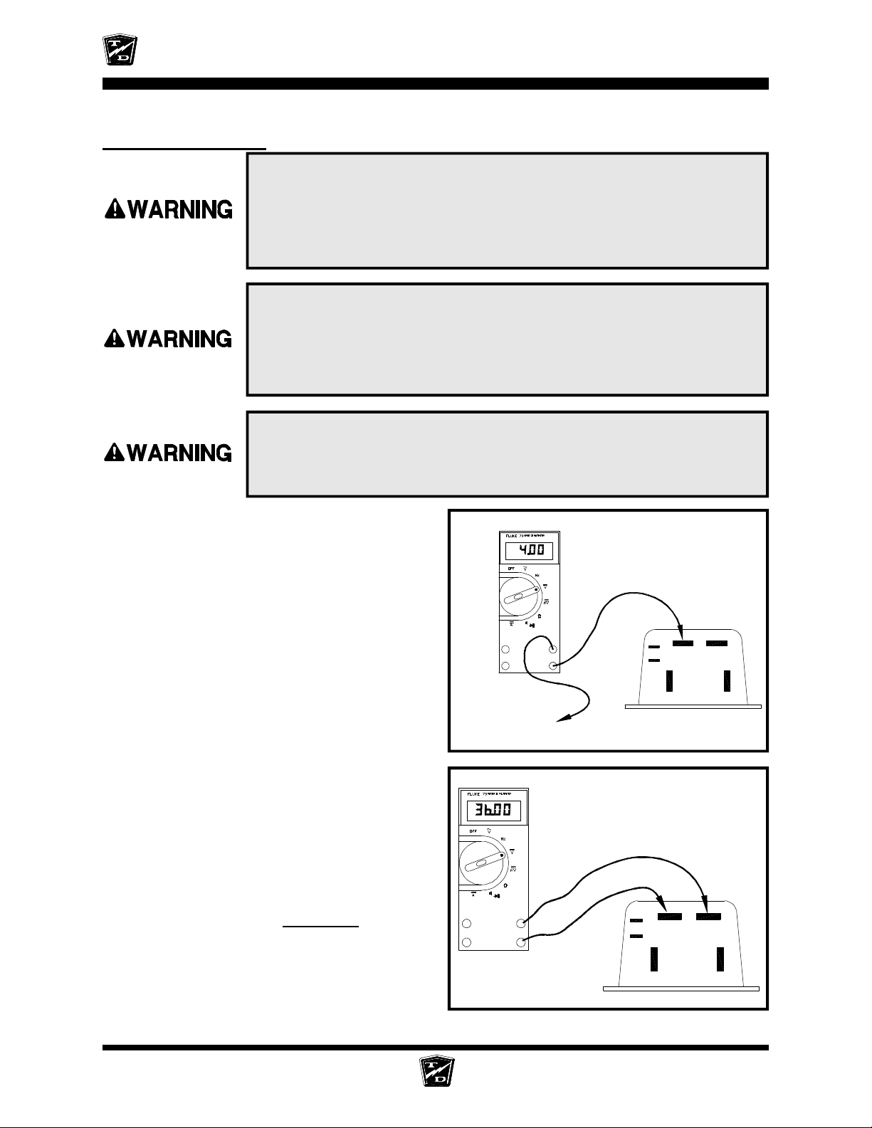
ELECTRICAL TROUBLESHOOTING
Power Wire Inputs
1. Make sure the key-switch is in the “OFF” position, then remove
the key.
2. Place the forward-reverse switch in the center “OFF” position.
3. Set the park brake.
4. Place blocks under the front wheels to prevent vehicle movement.
The rear drive wheels may rotate during some of the following tests.
Block the front wheels, raise the rear drive wheels off the ground,
and support the vehicle with jack stands. Failure to do so may cause
the vehicle to move and cause property damage and/or serious bodily
injury.
Rotating rear drive wheels are a potential hazard. Keep hands, arms,
legs and loose clothing away from the rear drive wheels while
conducting tests. Failure to do so may cause serious bodily injury.
Connect a voltmeter to the PMC ‘B-’ terminal
and battery positive.
• If the voltage is not the same as battery
volts then there is an open circuit in the
wire from ‘B-’ to the battery. Stop
troubleshooting here and repair the
problem. When the repair is completed,
completely retest the vehicle before
lowering the drive wheels to the ground.
Connect a voltmeter across the PMC ‘B-’
terminal and the PMC ‘B+’ terminal.
Close all interlock switches, turn the Key
Switch ON, and place the F&R Switch in
Forward.
Depress the accelerator pedal to engage
MS-1 only.
•
If the voltage is not the same as battery
volts then go to the
•
If the voltage is the same as battery volts
then the PMC controller has failed. Stop
trouble shooting here and repair the
problem. When the repair is completed,
completely retest the vehicle before
lowering the drive wheels to the ground.
Solenoids
sequence.
+
_
Main Battery Positive
The voltage shown is for illustration
only. The actual voltage may vary.
+
_
The voltage shown is for illustration
only. The actual voltage may vary.
KSI
B-
B+
M-
A2
B+
KSI
#2
#2
B-
M-
A2
SECTION 4 Main Sequence PAGE 8
Page 87
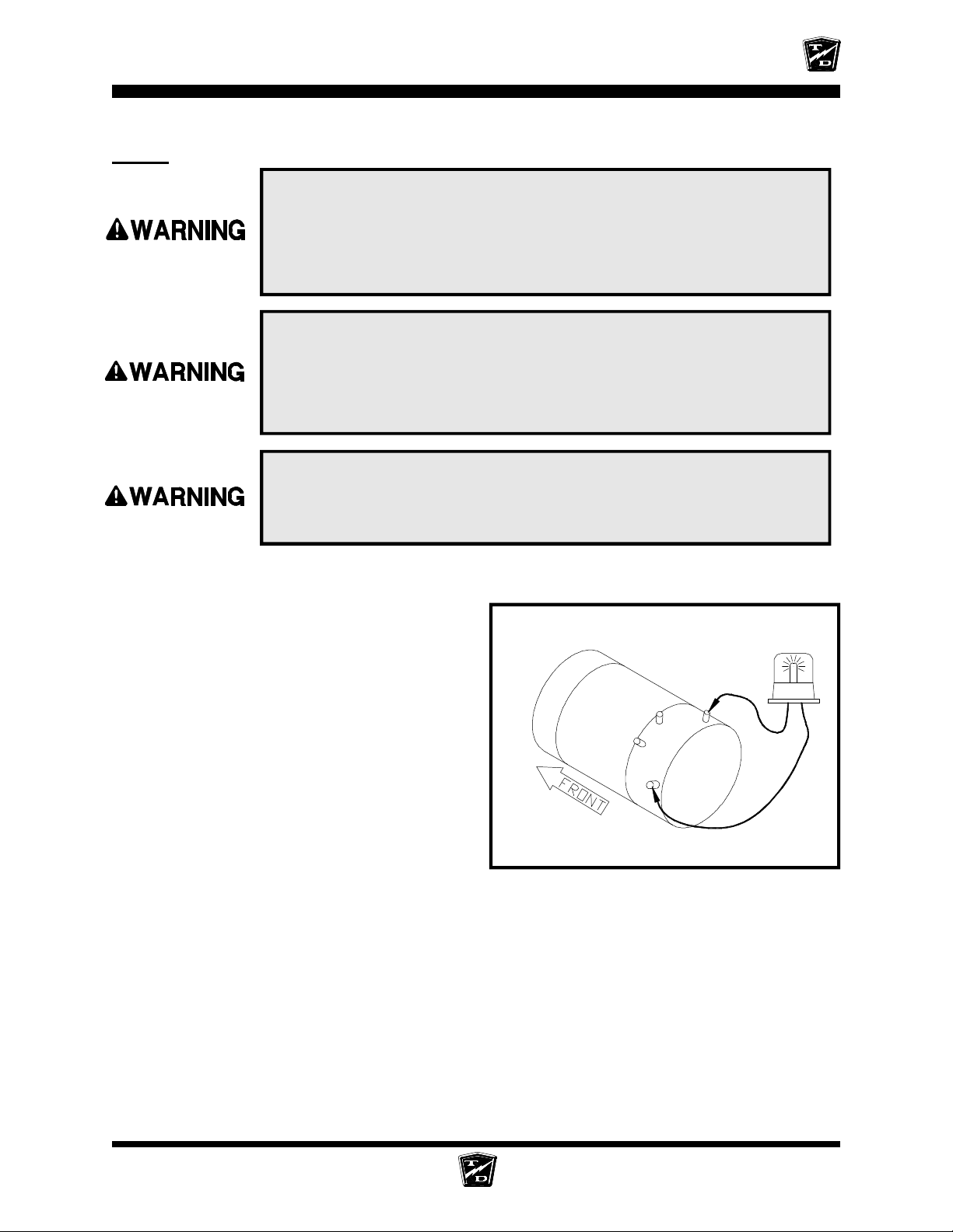
Motor
ELECTRICAL TROUBLESHOOTING
1. Make sure the key-switch is in the “OFF” position, then remove
the key.
2. Place the forward-reverse switch in the center “OFF” position.
3. Set the park brake.
4. Place blocks under the front wheels to prevent vehicle movement.
The rear drive wheels may rotate during some of the following tests.
Block the front wheels, raise the rear drive wheels off the ground,
and support the vehicle with jack stands. Failure to do so may cause
the vehicle to move and cause property damage and/or serious bodily
injury.
Rotating rear drive wheels are a potential hazard. Keep hands, arms,
legs and loose clothing away from the rear drive wheels while
conducting tests. Failure to do so may cause serious bodily injury.
Set the test light voltage to the same voltage as
the battery volts.
Connect the test light across the motor ‘A1’ and
‘A2’ terminals.
Close all interlock switches, turn the Key
Switch ON, and place the F&R Switch in
Forward.
Depress the accelerator fully.
•
If the light comes on then the motor
armature windings are open and the
motor must be repaired or replaced. Stop
trouble shooting here and repair the
problem. When the repair is completed,
completely test the vehicle before
lowering the drive wheels to the ground.
Wiring to motor omitted for clarity. Do not
disconnect the motor wires for this test.
S1
A2
S2
A1
Motor shown for reference only. Terminal positions
on your motor may not be in the same location.
SECTION 4 Main Sequence PAGE 9
Page 88
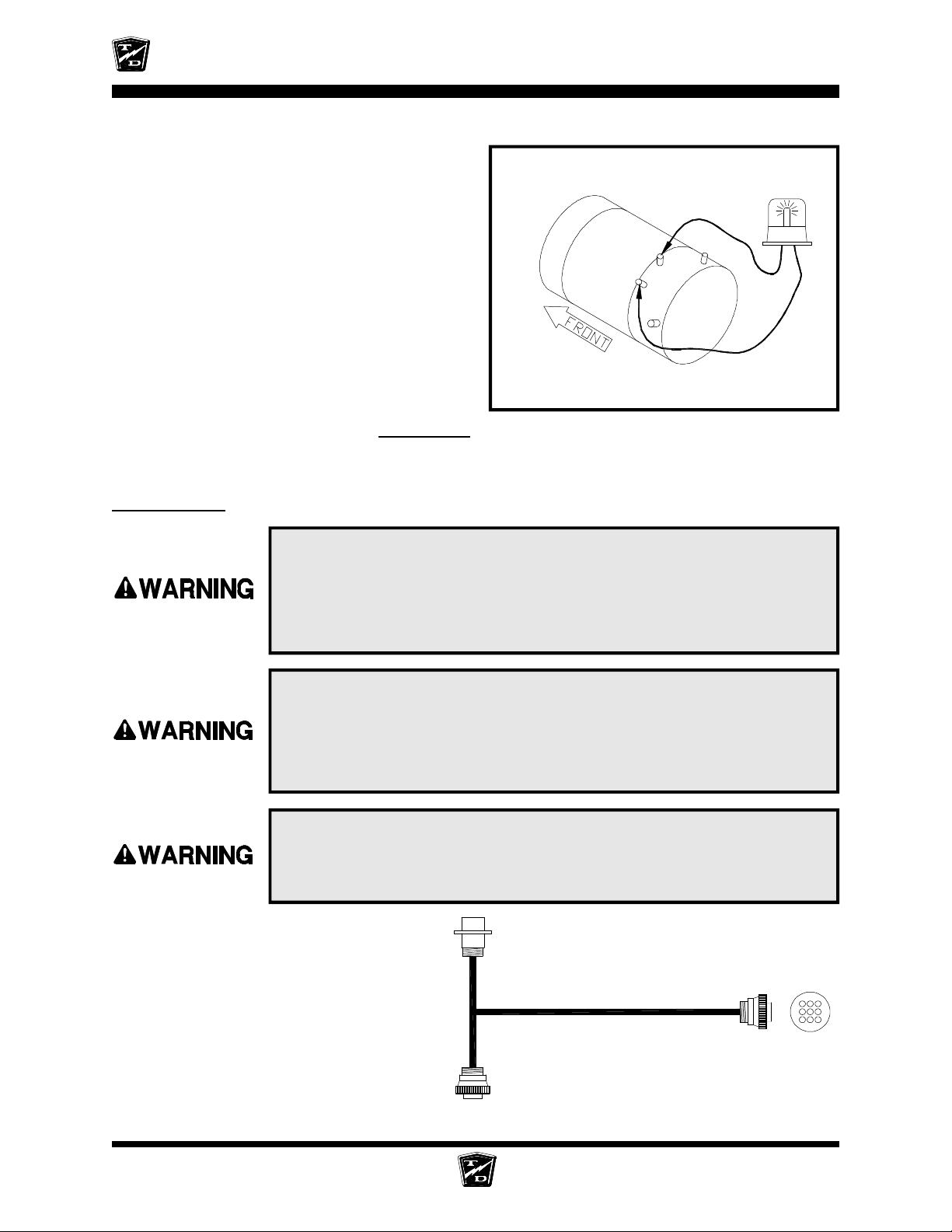
ELECTRICAL TROUBLESHOOTING
Connect the test light across the motor ‘S1’ and
‘S2’ terminals.
Close all interlock switches, turn the Key
Switch ON, and place the F&R Switch in
Forward.
Depress the accelerator fully.
•
If the light comes on then the motor field
windings are open and the motor must
be repaired or replaced. Stop trouble
shooting here and repair the problem.
When the repair is completed,
completely retest the vehicle before
lowering the drive wheels to the ground.
•
If the test light did not come on during
either test then go to the
F/R Switch
sequence.
Accelerator
1. Make sure the key-switch is in the “OFF” position, then remove
the key.
2. Place the forward-reverse switch in the center “OFF” position.
3. Set the park brake.
4. Place blocks under the front wheels to prevent vehicle movement.
Wiring to motor omitted for clarity. Do not
disconnect the motor wires for this test.
S1
A2
S2
A1
Motor shown for reference only. Terminal positions
on your motor may not be in the same location.
The rear drive wheels may rotate during some of the following tests.
Block the front wheels, raise the rear drive wheels off the ground,
and support the vehicle with jack stands. Failure to do so may cause
the vehicle to move and cause property damage and/or serious bodily
injury.
Rotating rear drive wheels are a potential hazard. Keep hands, arms,
legs and loose clothing away from the rear drive wheels while
conducting tests. Failure to do so may cause serious bodily injury.
This is the accelerator module test
harness part number 62-027-31. It will
be used in the following tests. These
tests cannot be completed without this
harness. If you do not have this harness,
one must be obtained before testing can
continue.
PLUG THIS END
INTO THE HARNESS
3 1
4
967
USE THIS END
FOR TESTING
PLUG THIS END
INTO THE MODULE
SECTION 4 Main Sequence PAGE 10
Page 89
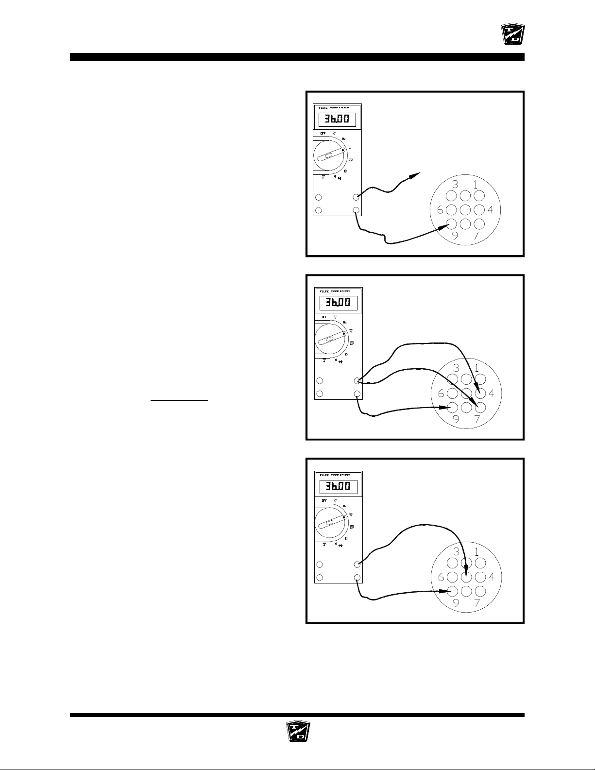
ELECTRICAL TROUBLESHOOTING
Connect the accelerator module test harness to
the accelerator module.
Connect a voltmeter between pin #9 in the test
harness and battery positive.
• If the voltage is not at battery volts then
the wiring between pin #9 in the harness
and battery negative is open. Stop
trouble shooting here and repair the
problem. When the repair is completed,
completely retest the vehicle before
lowering the drive wheels to the ground.
Connect a voltmeter negative probe to Pin #9
(-) in the test harness. Connect the positive
probe to:
24 or 36 volt truck - Pin #4
48 volt truck - Pin #7
The voltage shown is for illustration
only. The actual voltage may vary.
Main Battery Positive
+
-
The voltage shown is for illustration
only. The actual voltage may vary.
Close all interlock switches and turn the
Key Switch ON.
•
If the voltage is not at battery volts then
go to the
Key Switch
sequence.
Connect a voltmeter between pin #9 (-) and pin
#5 (+) in the test harness.
Close all interlock switches and turn the
Key Switch ON.
Depress the accelerator pedal to engage
MS-1 only.
•
If the voltage is not at battery volts then
the accelerator module has failed. Stop
trouble shooting here and repair the
problem. When the repair is completed,
completely retest the vehicle before
lowering the drive wheels to the ground.
•
If the voltage at pin #5 is good but the
test at the center terminal of the forward
and reverse side of the F&R switch in
the Key Switch Section failed then check the wire between the accelerator module pin #5
and the F&R switch. Stop trouble shooting here and repair the problem. When the repair
is completed, completely retest the vehicle before lowering the drive wheels to the ground.
24-36-volt
+
-
48-volt
The voltage shown is for illustration
only. The actual voltage may vary.
+
-
SECTION 4 Main Sequence PAGE 11
Page 90
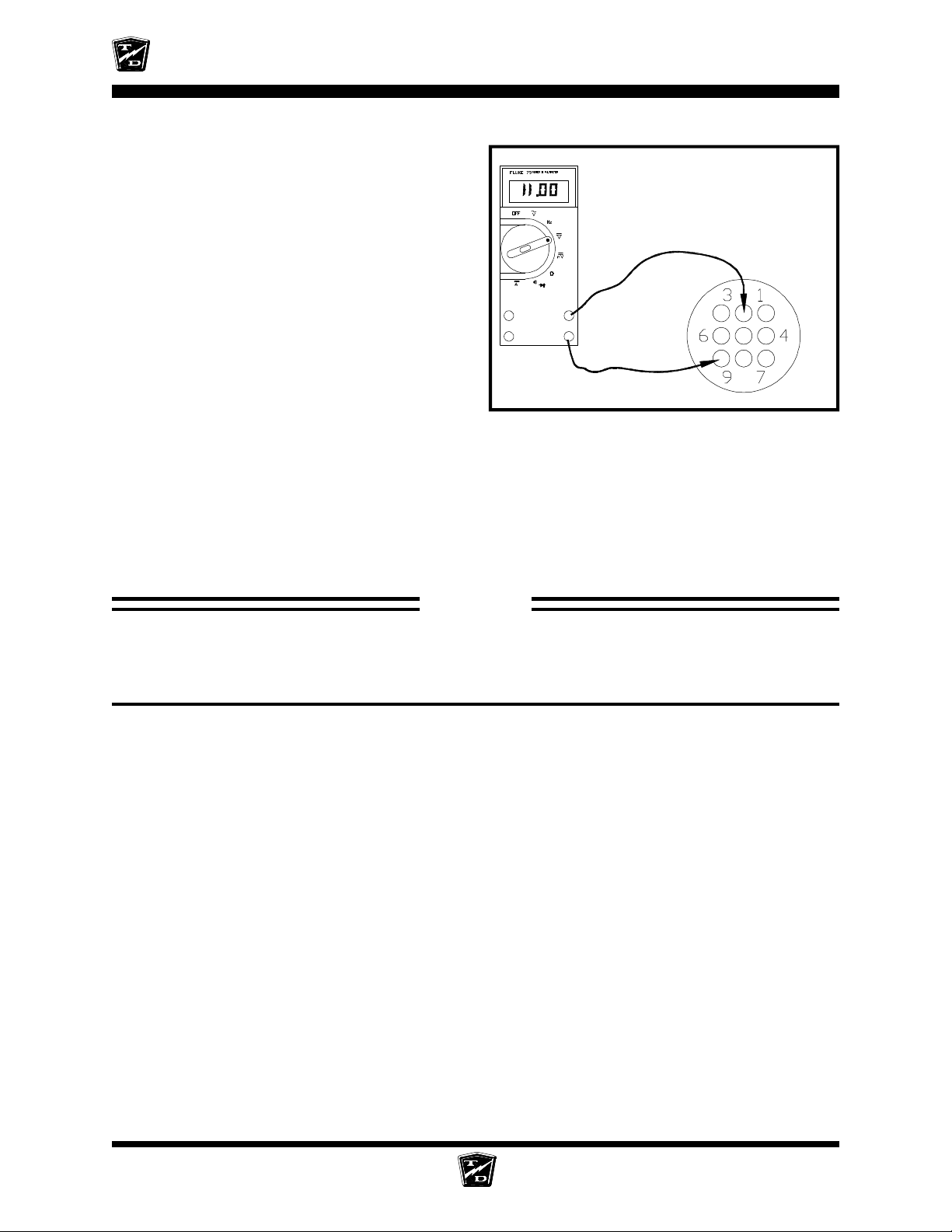
ELECTRICAL TROUBLESHOOTING
Connect a voltmeter between pin #9 (-) and pin
#2 (+) in the test harness.
Depress the accelerator pedal to engage
MS-1 only.
•
If the voltage is between 6.0 and 6.5 volts
and the test at the PMC #2 terminal in
the Control Wire Input section failed then
the wire or interlock switches between
the accelerator module pin #2 and the
PMC pin #2 is open. Stop trouble
shooting here and repair the problem.
When the repair is completed,
completely retest the vehicle before
lowering the drive wheels to the ground.
•
If the voltage is not between 6.0 and 6.5
volts then the accelerator module has failed. Stop trouble shooting here and repair the
problem. When the repair is completed, completely retest the vehicle before lowering the
drive wheels to the ground.
Now Depress the accelerator module fully.
•
If the voltage is not between 11.0 and 11.5 volts then the accelerator module has failed.
Stop trouble shooting here and repair the problem. When the repair is completed,
completely retest the vehicle before lowering the drive wheels to the ground.
The voltage shown is for illustration
only. The actual voltage may vary.
+
-
STOP
Stop, do not continue. If you reached this point without a solution, then you may have an
unanticipated problem or have made an error during testing. It is important to review the
trouble shooting steps that have led to this point. The tests may need to be repeated.
SECTION 4 Main Sequence PAGE 12
Page 91
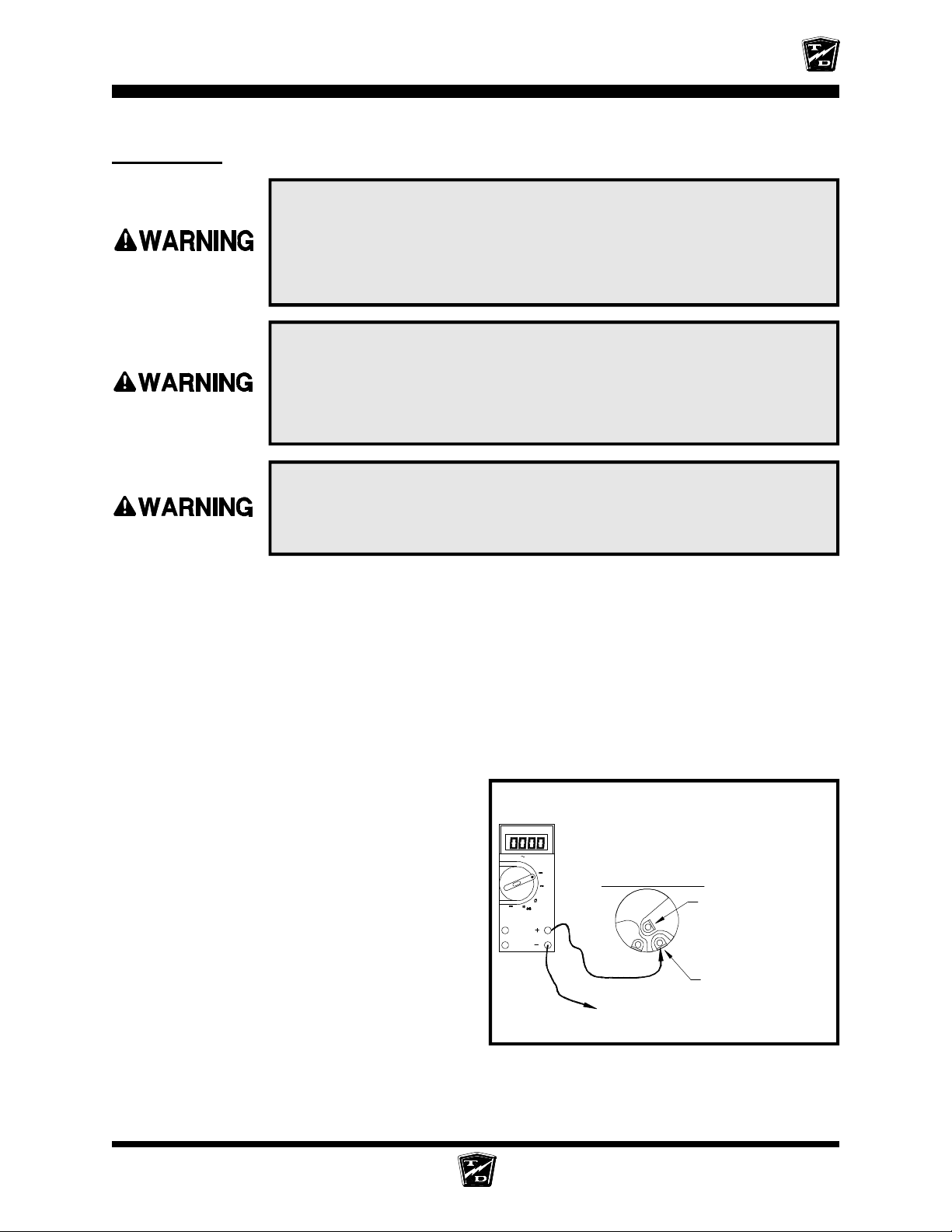
Key Switch
ELECTRICAL TROUBLESHOOTING
1. Make sure the key-switch is in the “OFF” position, then remove
the key.
2. Place the forward-reverse switch in the center “OFF” position.
3. Set the park brake.
4. Place blocks under the front wheels to prevent vehicle movement.
The rear drive wheels may rotate during some of the following tests.
Block the front wheels, raise the rear drive wheels off the ground,
and support the vehicle with jack stands. Failure to do so may cause
the vehicle to move and cause property damage and/or serious bodily
injury.
Rotating rear drive wheels are a potential hazard. Keep hands, arms,
legs and loose clothing away from the rear drive wheels while
conducting tests. Failure to do so may cause serious bodily injury.
Test all interlock switches and/or interlock relays (if equipped) for continuity. Depending on the
model of your vehicle, it may have a seat interlock, Foot interlock, Charger interlock, special
order interlock or any combination of the above. Refer to the wire diagram at the end of this
section for location of the interlocks.
NOTE: Due to the many different configurations possible for special order
interlocks, they will not be included in this text. Refer to the option
list for your truck or contact your Taylor-Dunn® Representative for
more information.
If you do not know how to test for continuity,
refer test to a qualified technician.
Connect a voltmeter across the HOT terminal of
the key switch and battery negative.
•
If the voltage is not at battery volts then
check the wire between the key switch
and battery positive. Stop trouble
shooting here and repair the problem.
FLUKE 79
OFF
V
Hz
A
View of the terminals of a
typical Key Switch
V
mV
KEY SWITCH
"COLD, Violet Wire(s)"
SERIES II MULTIMETER
When the repair is completed,
completely retest the vehicle before
lowering the drive wheels to the ground.
"HOT, Red wire(s)"
BATTERY MAIN NEGATIVE
SECTION 4 Main Sequence PAGE 13
Page 92
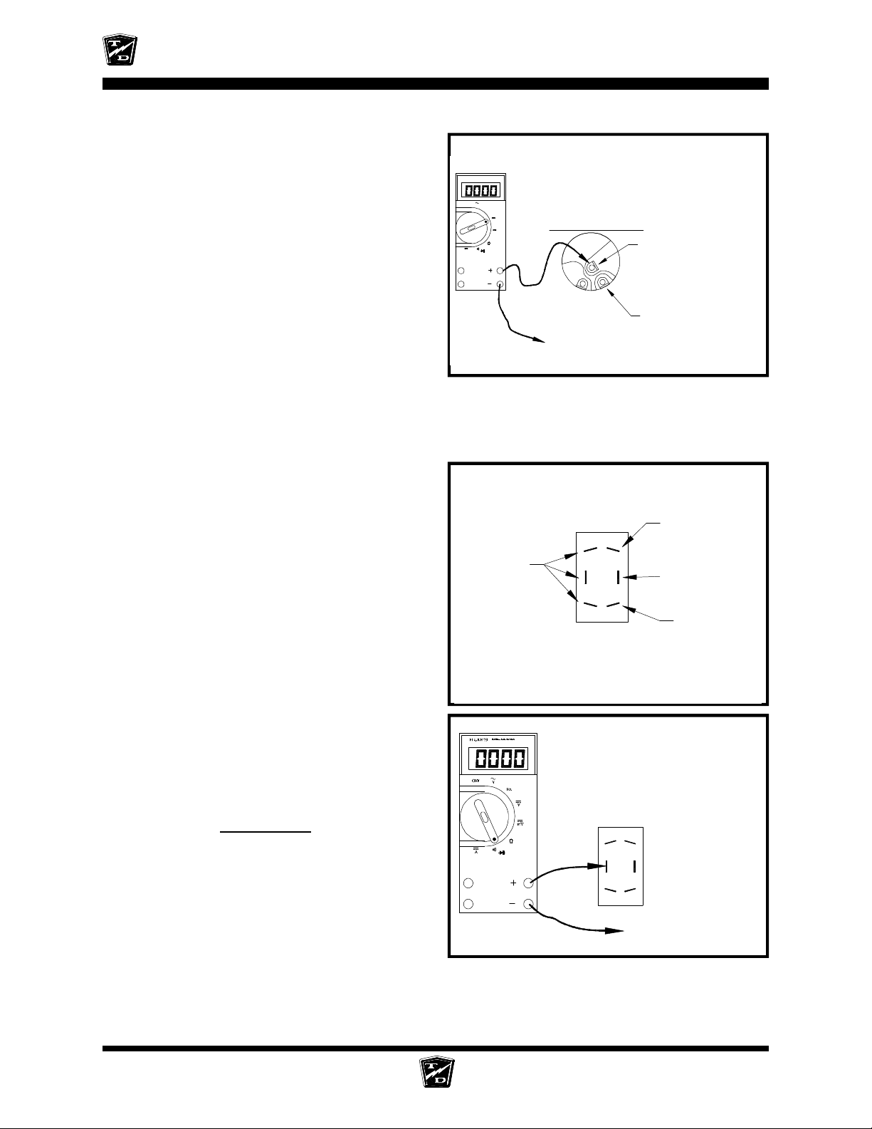
ELECTRICAL TROUBLESHOOTING
Connect a voltmeter across the COLD terminal
of the key switch and battery negative.
Turn the key switch ON.
•
If the voltage is not at battery volts then
the key switch has failed. Stop trouble
shooting here and repair the problem.
When the repair is completed,
completely retest the vehicle before
lowering the drive wheels to the ground.
•
If the voltage is at battery volts but the
previous test at pin #4 in the Accelerator
section failed then check the wire from
the key switch to pin #4 at the accelerator
module. Stop trouble shooting here and
repair the problem. When the repair is
completed, completely retest the vehicle
before lowering the drive wheels to the
ground.
For your reference, shown at the right are the
Forward and Reverse switch wire connections
for a typical control system.
SERIES II MULTIMETER
FLUKE 79
OFF
V
Hz
V
mV
A
Violet/Black
View of the terminals of a
typical Key Switch
KEY SWITCH
BATTERY MAIN NEGATIVE
Forward and Reverse Side
KSI Side
"COLD, Violet Wires(s)"
"HOT, Red wire(s)"
White/Black
Green/Black
Connect a voltmeter across the HOT terminal of
the KSI side of the F&R switch and battery
negative.
Turn the key switch ON.
•
If the voltage is not at battery volts then
go to the
Accelerator
sequence.
Blue/Black
Typical configuration of the
terminals on a Forward and
Reverse Switch as viewed
from the back
The HOT terminal is the Violet/Black
wire on the center terminal
Battery Negative
SECTION 4 Main Sequence PAGE 14
Page 93
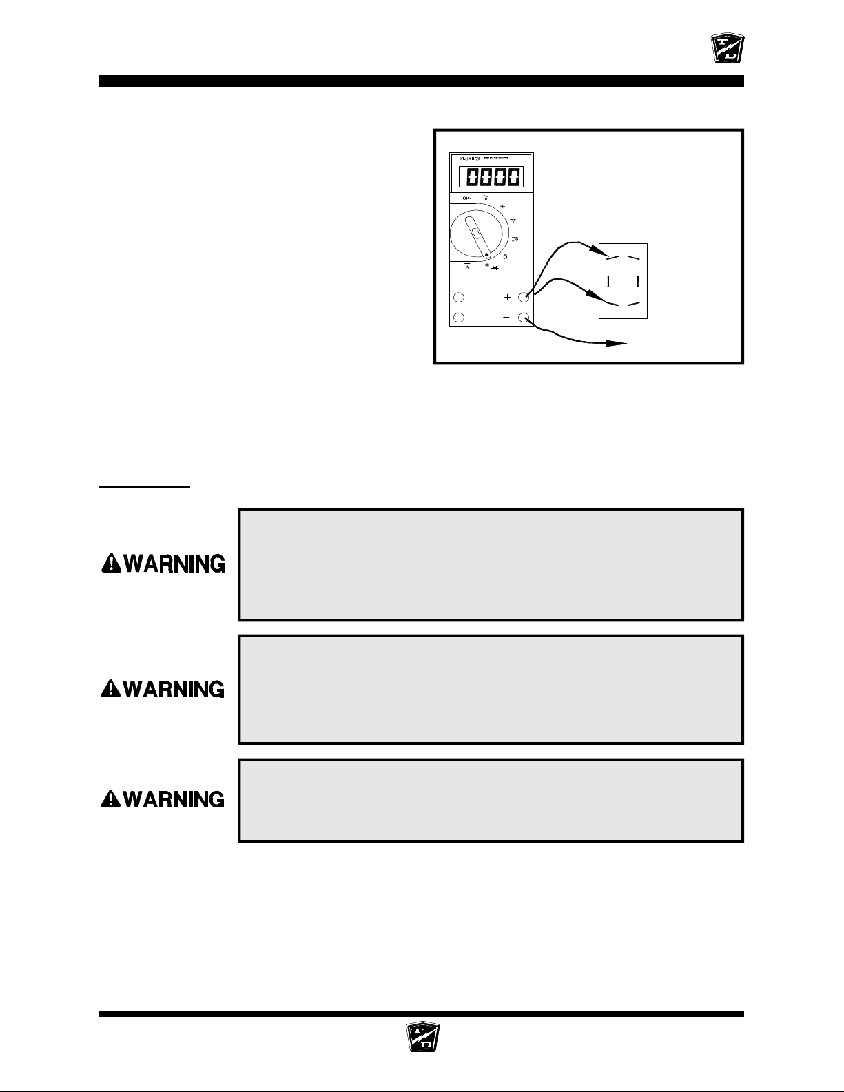
ELECTRICAL TROUBLESHOOTING
Connect a voltmeter across one of the COLD
terminals of the KSI side of the F&R switch and
battery negative.
Close all interlock switches, turn the Key
Switch ON, and place the F&R Switch in
Forward.
•
If the voltage is not at battery volts then
the F&R switch has failed. Stop trouble
shooting here and repair the problem.
When the repair is completed,
completely retest the vehicle before
lowering the drive wheels to the ground.
•
If the voltage is at battery volts and the
test at the PMC KSI terminal in the
Control Wire Inputs section failed then
check the wiring between COLD terminals of the KSI side of the F&R switch and the PMC
KSI terminal. Stop trouble shooting here and repair the problem. When the repair is
completed, completely retest the vehicle before lowering the drive wheels to the ground.
The COLD terminal is the
Violet/Black wire on either
end of the switch
Or,
Battery Negative
F/R switch
1. Make sure the key-switch is in the “OFF” position, then remove
the key.
2. Place the forward-reverse switch in the center “OFF” position.
3. Set the park brake.
4. Place blocks under the front wheels to prevent vehicle movement.
The rear drive wheels may rotate during some of the following tests.
Block the front wheels, raise the rear drive wheels off the ground,
and support the vehicle with jack stands. Failure to do so may cause
the vehicle to move and cause property damage and/or serious bodily
injury.
Rotating rear drive wheels are a potential hazard. Keep hands, arms,
legs and loose clothing away from the rear drive wheels while
conducting tests. Failure to do so may cause serious bodily injury.
SECTION 4 Main Sequence PAGE 15
Page 94
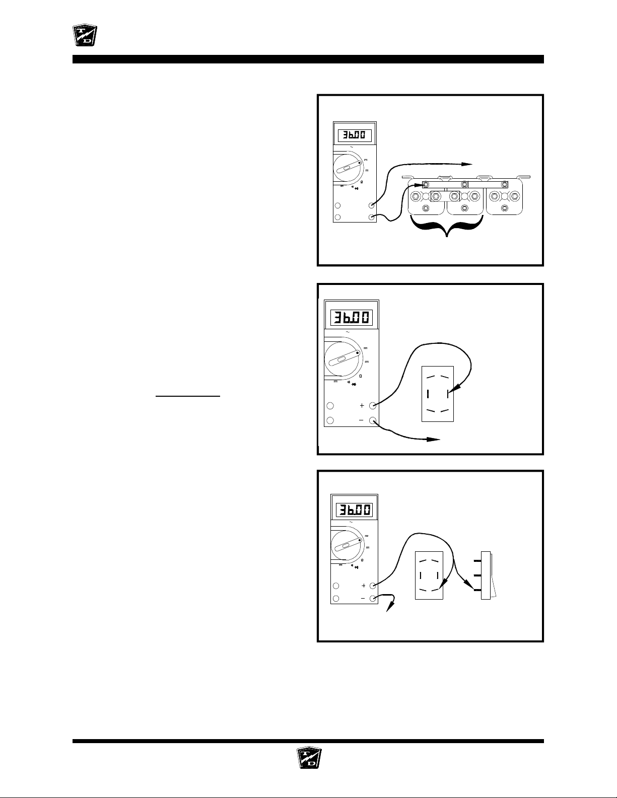
ELECTRICAL TROUBLESHOOTING
Connect a voltmeter across the Solenoid
Negative Buss Bar and battery positive.
NOTE: You may skip this test if it was
completed in a previous section
•
If the voltage is not at battery volts then
check the wiring to battery negative and
the negative circuit breaker. Stop trouble
shooting here and repair the problem.
When the repair is completed,
completely retest the vehicle before
lowering the drive wheels to the ground.
Connect a voltmeter across the center terminal
of the forward and reverse side of the F&R switch
and battery negative.
Close all interlock switches, turn the Key
Switch ON, and place the F&R Switch in
Forward.
Depress the accelerator pedal fully.
•
If the voltage is not at battery volts then
go to the
Accelerator
sequence.
FLUKE 79
OFF
A
FLUKE 79
OFF
A
SERIES II MULTIMETER
V
SERIES II MULTIMETER
V
The voltage shown is for illustration
only. The actual voltage may vary.
Solenoids are shown for reference only.
The type of solenoid in your truck may
Hz
look different
V
mV
+
-
FWD/REV
The CENTER terminal is the
Green/Black wire
Hz
V
mV
Main Battery
Positive
ISO
Connect a voltmeter across the forward terminal
of the forward and reverse side of the F&R switch
and battery negative.
Close all interlock switches, turn the Key
Switch ON, and place the F&R Switch in
forward.
Depress the accelerator pedal fully.
•
If the voltage is not at battery volts then
the F&R switch has failed. Stop trouble
shooting here and repair the problem.
When the repair is completed,
completely retest the vehicle before
lowering the drive wheels to the ground.
SERIES II MULTIMETER
FLUKE 79
OFF
V
Hz
V
mV
A
Battery Negative
Battery Negative
The FORWARD terminal is
diagonally opposite the forward side
of the rocker on the switch
F&R switch seen from
the side depressed in
the FORWARD gear
F&R switch seen
from the rear
SECTION 4 Main Sequence PAGE 16
Page 95
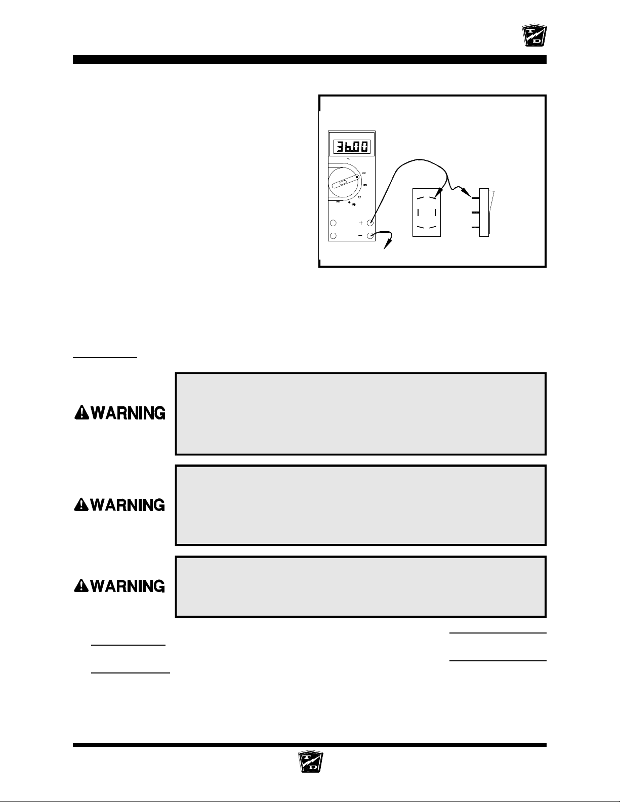
ELECTRICAL TROUBLESHOOTING
Connect a voltmeter across the reverse terminal
of the forward and reverse side of the F&R switch
and battery negative.
Close all interlock switches, turn the Key
Switch ON, and place the F&R Switch in
reverse.
Depress the accelerator pedal fully.
•
If the voltage is not at battery volts then
the F&R switch has failed. Stop trouble
shooting here and repair the problem.
When the repair is completed,
completely retest the vehicle before
lowering the drive wheels to the ground.
•
If all tests in this section were good then
check the wiring from the F&R switch to
the Forward and Reverse solenoids and both the forward and reverse solenoid coils.
Stop trouble shooting here and repair the problem. When the repair is completed,
completely retest the vehicle before lowering the drive wheels to the ground.
SERIES II MULTIMETER
FLUKE 79
OFF
V
Hz
V
mV
A
Battery Negative
The REVERSE terminal is diagonally
opposite the reverse side of the
rocker on the switch
F&R switch seen from
the side depressed in
the REVERSE gear
F&R switch seen
from the rear
Solenoids
1. Make sure the key-switch is in the “OFF” position, then remove
the key.
2. Place the forward-reverse switch in the center “OFF” position.
3. Set the park brake.
4. Place blocks under the front wheels to prevent vehicle movement.
The rear drive wheels may rotate during some of the following tests.
Block the front wheels, raise the rear drive wheels off the ground,
and support the vehicle with jack stands. Failure to do so may cause
the vehicle to move and cause property damage and/or serious bodily
injury.
Rotating rear drive wheels are a potential hazard. Keep hands, arms,
legs and loose clothing away from the rear drive wheels while
conducting tests. Failure to do so may cause serious bodily injury.
If the vehicle runs in forward only then skip ahead to the test sequence
run in reverse
If the vehicle runs in reverse only then skip ahead to the test sequence
run in forward)
).
.
Forward (does not
Reverse (does not
SECTION 4 Main Sequence PAGE 17
Page 96
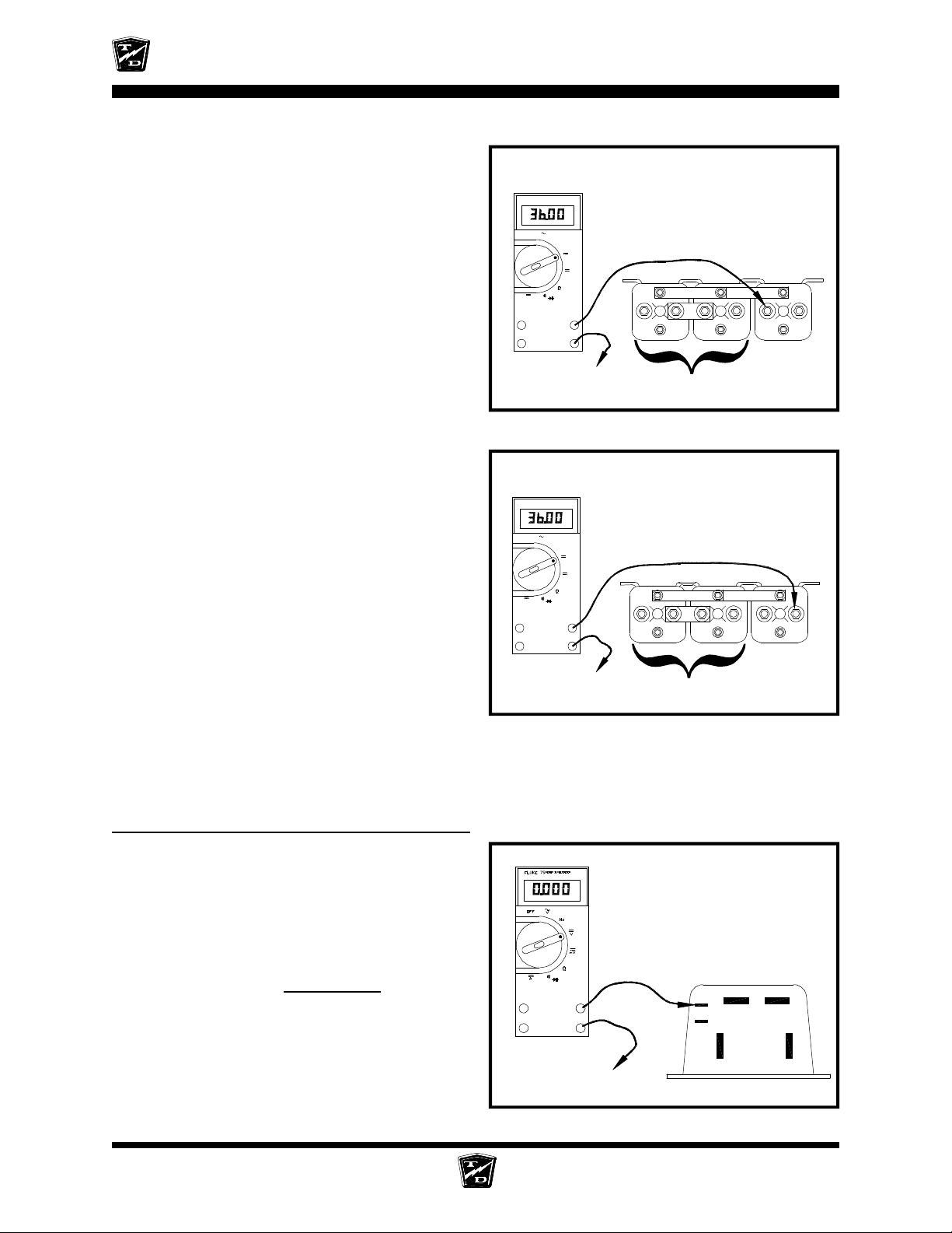
ELECTRICAL TROUBLESHOOTING
Connect a voltmeter across the ISO solenoid
COLD terminal and battery negative.
Close all interlock switches and turn the
Key Switch ON.
Depress the accelerator pedal fully.
•
If the voltage is at battery volts then
the wire from the ISO solenoid to the
PMC is bad. Stop trouble shooting
here and repair the problem. When
the repair is completed, completely
retest the vehicle before lowering the
drive wheels to the ground.
Connect a voltmeter across the ISO solenoid
HOT terminal and battery negative.
Close all interlock switches and turn the
Key Switch ON.
Depress the accelerator pedal fully.
•
If the voltage is at battery volts then the
ISO solenoid has failed. Stop trouble
shooting here and repair the problem.
When the repair is completed,
completely retest the vehicle before
lowering the drive wheels to the ground.
•
If the voltage is not at battery volts then
check the wiring to battery positive and
the main circuit breaker. Stop trouble
shooting here and repair the problem.
When the repair is completed, completely retest the vehicle before lowering the drive
wheels to the ground.
The voltage shown is for illustration
FLUKE 79
OFF
SERIES II MULTIMETER
V
A
only. The actual voltage may vary.
Solenoids are shown for reference only.
Hz
V
mV
+
_
Battery Negative
The voltage shown is for illustration
FLUKE 79
OFF
SERIES II MULTIMETER
V
A
only. The actual voltage may vary.
Solenoids are shown for reference only.
The type of solenoid in your truck may
Hz
look different
V
mV
+
_
Battery Negative
The type of solenoid in your truck may
look different
ISO
FWD/REV
ISO
FWD/REV
Forward (does not run in reverse)
Connect a voltmeter across the PMC KSI
terminal and battery negative.
Close all interlock switches, turn the
Key Switch ON, and place the F&R
Switch in reverse.
•
If the voltage is not at battery volts
then go to the
Key Switch
sequence.
SECTION 4 Main Sequence PAGE 18
The voltage shown is for illustration
only. The actual voltage may vary.
+
_
Main Battery Negative
KSI
B-
#2
B+
M-
A2
Page 97
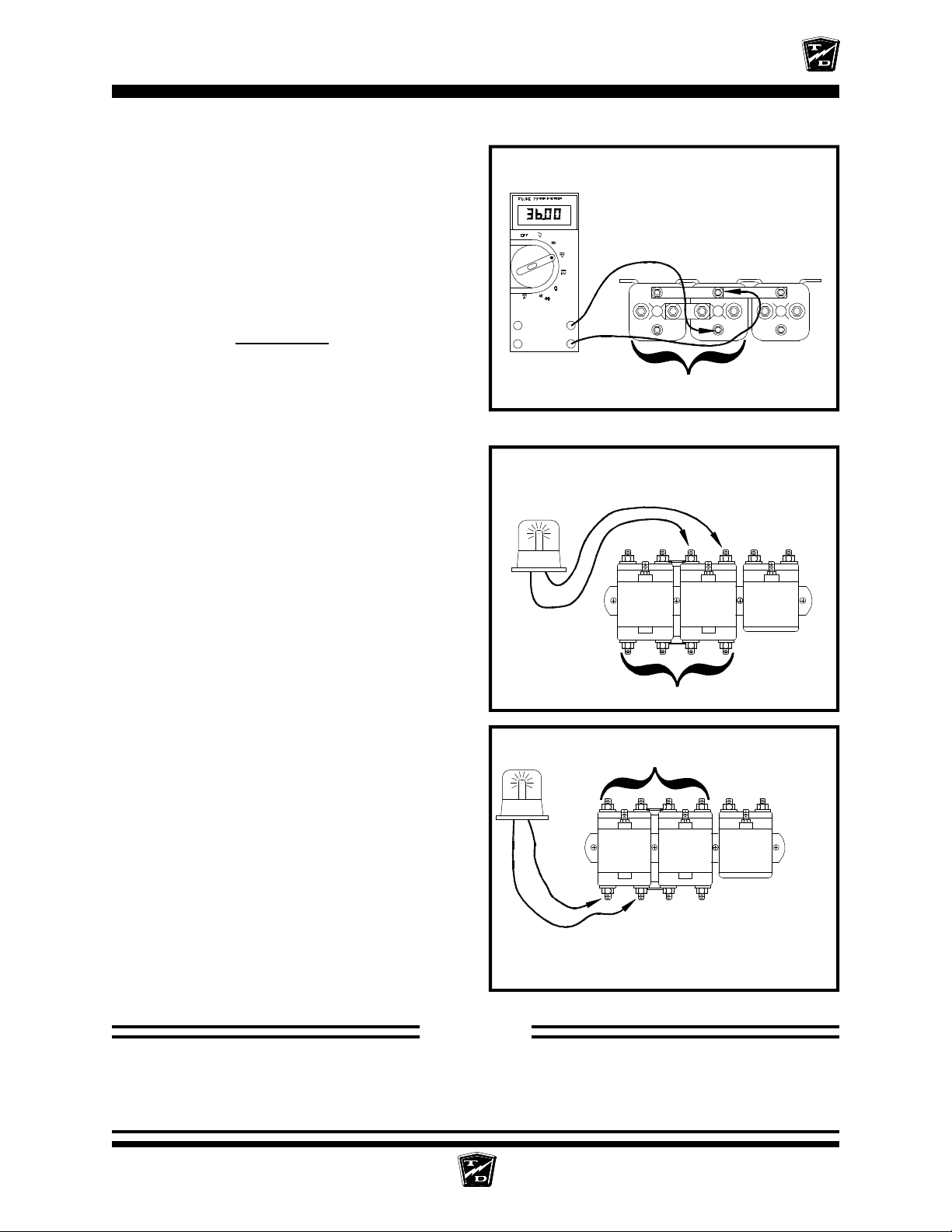
ELECTRICAL TROUBLESHOOTING
Connect a voltmeter across the Reverse Solenoid
coil terminals. Refer to your vehicles wiring
diagram to identify the position of the reverse
solenoid.
Close all interlock switches, turn the Key
Switch ON, and place the F&R Switch in
reverse.
Depress the accelerator pedal fully.
•
If the voltage is not at battery volts then
go to the
Set the test light voltage to the same voltage as
the battery volts.
F/R Switch
sequence.
The voltage shown is for illustration
only. The actual voltage may vary.
Solenoids are shown for reference only.
The type and position of the reverse
solenoid in your truck may be different
+
_
FWD/REV
ISO
Connect the test light across the normally open
contacts of the reverse solenoid. Refer to your
vehicles wiring diagram to identify the position
of the reverse solenoid.
Close all interlock switches, turn the Key
Switch ON, and place the F&R Switch in
reverse.
Depress the accelerator pedal fully.
•
If the light comes on then the Reverse
solenoid has failed. Stop trouble shooting
here and repair the problem. When the
repair is completed, completely retest the
vehicle before lowering the drive wheels
to the ground.
Connect the test light across the Normally Closed
contacts of the Forward solenoid. Refer to your
vehicles wiring diagram to identify the position
of the forward solenoid.
Close all interlock switches, turn the Key
Switch ON, and place the F&R Switch in
Reverse.
Depress the accelerator pedal fully.
•
If the light comes on then the Forward
solenoid has failed. Stop trouble shooting
here and repair the problem. When the
repair is completed, completely retest the
vehicle before lowering the drive wheels to the ground.
Solenoids are shown for reference only.
The type and position of the reverse
solenoid in your truck may be different
FWD/REV
FWD/REV
Solenoids are shown for reference only.
The type and position of the forward
solenoid in your truck may be different
STOP
Stop, do not continue. If you reached this point without a solution, then you may have an
unanticipated problem or have made an error during testing. It is important to review the
trouble shooting steps that have led to this point. The tests may need to be repeated.
SECTION 4 Main Sequence PAGE 19
Page 98
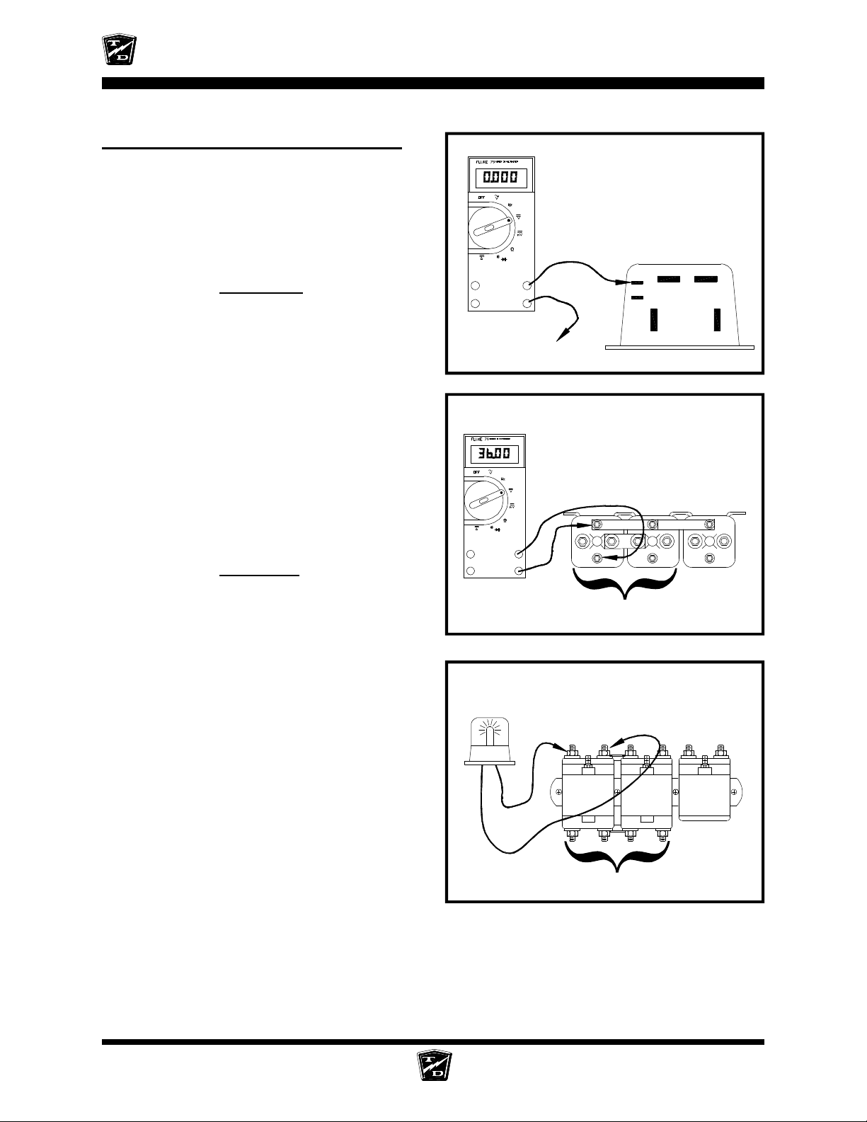
ELECTRICAL TROUBLESHOOTING
Reverse (does not run in forward)
Connect a voltmeter across the PMC KSI
terminal and battery negative.
Close all interlock switches, turn the Key
Switch ON, and place the F&R Switch in
forward.
•
If the voltage is not at battery volts then
go to the
Key Switch
sequence.
Connect a voltmeter across the Forward Solenoid
coil terminals. Refer to your vehicles wiring
diagram to identify the position of the forward
solenoid.
Close all interlock switches, turn the Key
Switch ON, and place the F&R Switch in
forward.
Depress the accelerator pedal fully.
•
If the voltage is not at battery volts then
go to the
F/R Switch
sequence.
The voltage shown is for illustration
only. The actual voltage may vary.
+
_
Main Battery Negative
The voltage shown is for illustration
only. The actual voltage may vary.
Solenoids are shown for reference only.
The type and position of the forward
solenoid in your truck may be different
+
_
KSI
B-
#2
B+
M-
A2
ISO
Set the test light voltage to the same voltage as
the battery volts.
Connect the test light across the Normally Open
contacts of the Forward solenoid. Refer to your
vehicles wiring diagram to identify the position
of the forward solenoid.
Close all interlock switches, turn the Key
Switch ON, and place the F&R Switch in
forward.
Depress the accelerator pedal fully.
•
If the light comes on then the Forward
solenoid has failed. Stop trouble shooting
here and repair the problem. When the
repair is completed, completely retest the
vehicle before lowering the drive wheels
to the ground.
FWD/REV
Solenoids are shown for reference only.
The type and position of the forward
solenoid in your truck may be different
FWD/REV
SECTION 4 Main Sequence PAGE 20
Page 99
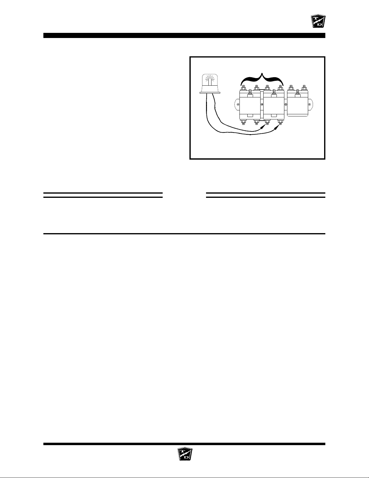
ELECTRICAL TROUBLESHOOTING
Set the test light voltage to the same voltage as
the battery volts.
Connect the test light across the Normally Closed
contacts of the Reverse solenoid. Refer to your
vehicles wiring diagram to identify the position
of the Reverse solenoid.
Close all interlock switches, turn the Key
Switch ON, and place the F&R Switch in
Forward.
Depress the accelerator pedal fully.
•
If the light comes on then the Reverse
solenoid has failed. Stop trouble shooting
here and repair the problem. When the
repair is completed, completely retest the
vehicle before lowering the drive wheels to the ground.
FWD/REV
Solenoids are shown for reference only.
The type and position of the reverse
solenoid in your truck may be different
STOP
Stop, do not continue. If you reached this point without a solution, then you may have an
unanticipated problem or have made an error during testing. It is important to review the
trouble shooting steps that have led to this point. The tests may need to be repeated.
SECTION 4 Main Sequence PAGE 21
Page 100
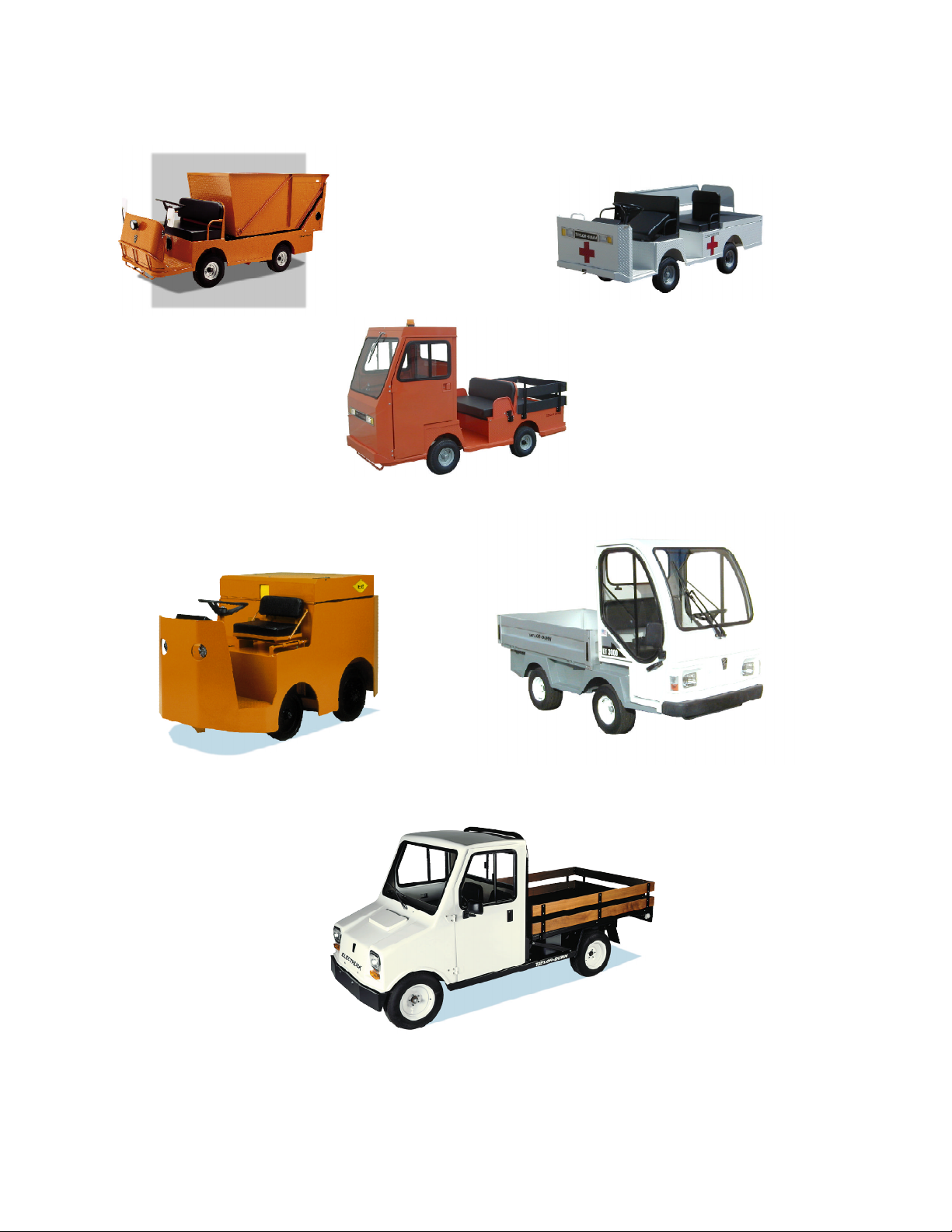
B2-48 With Dump Bed Option
B2-10 Ambulance
B2-48 with Steel Cab, Foldaway
4-Passenger Seat and Stake Sides
P2-50 30,000 Pound Tow Tractor
ET 3000
ET1-50 Full Size Truck
 Loading...