

Taylor-Dunn B0-248-36, B 2-48, B0-254-36, B0-248-48, B 2-54 Operation, T Roubleshooting And Replacement Parts Manual
...Page 1
®
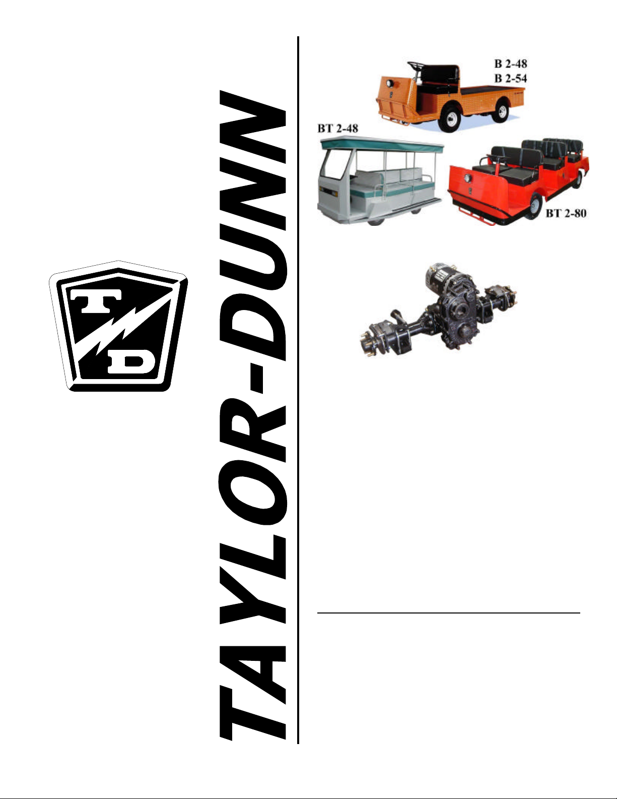
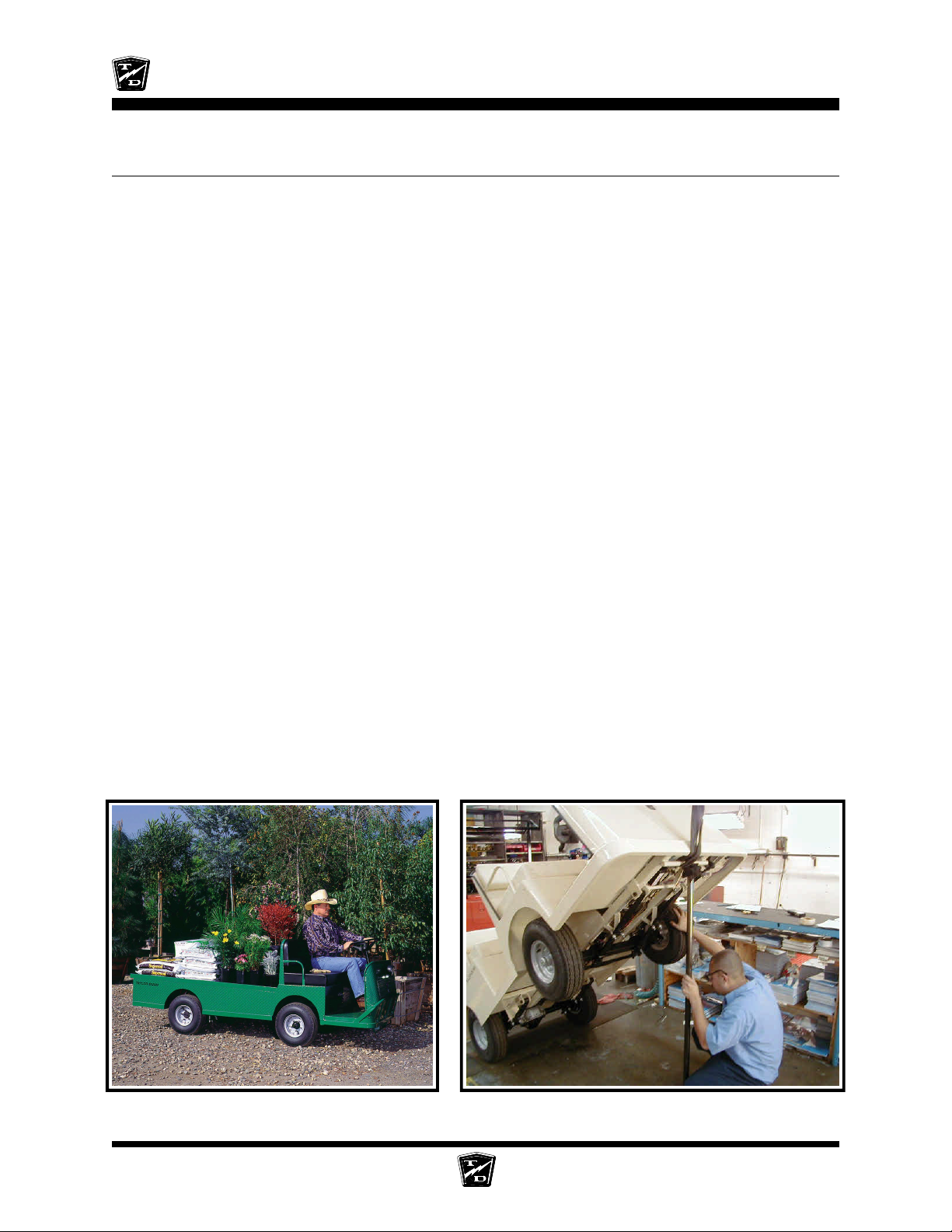
Shown with optional equipment installed
GT Drive
EQUIPPED WITH GT-DRIVE SYSTEM
The Best Way
To Go
About Your
Business
Models Inlcuded:
B0-248-36 (B 2-48, 36-volt)
B0-248-48 (B 2-48, 48-volt)
B0-254-36 (B 2-54)
BT-248-36 (36-volt Back to Back Tram)
BT-248-48 (48-volt Back to Back Tram)
BT-280-36 (36-volt 10-passenger Tram)
BT-280-48 (48-volt 10-passenger Tram)
MANUAL MB-248-12
Operation, Troubleshooting and
Replacement Parts Manual
Published 7/7/2008
Revision: B
Serial Number Starting 177127
Page 2

Page 3

Taylor-Dunn Contact information
Service, Parts, Sales:
Taylor-Dunn has a network of dealers distributed around the globe to support our
vehicles. Information regarding vehicle sales, replacement parts, or service should be
obtained through your local dealer. A dealer locator can be found on the Taylor-Dunn
website at www.taylor-dunn.com.
If you do not have access to the internet, you can call the factory direct at:
01 (714) 956-4040
Feedback regarding this or any Taylor-Dunn vehicle manual can be sent to:
Taylor-Dunn Manufacturing
Attn: Tech Writer
2114 West Ball Road
Anaheim, CA 92804
Page 4
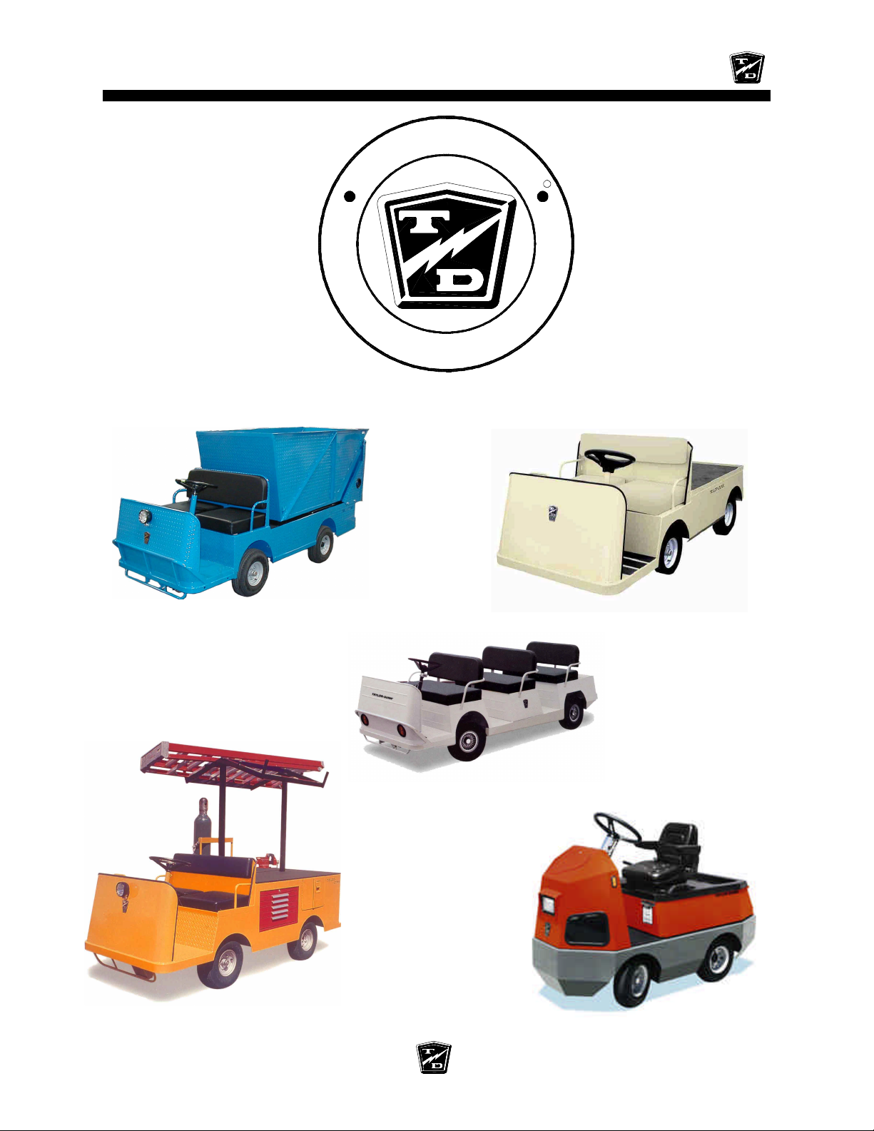
Table of Contents
-
R
A
D
U
N
N
R
s
s
e
n
i
s
u
B
r
u
o
Y
t
u
o
b
O
L
Y
A
T
T
h
e
B
e
s
t
W
a
y
T
o
G
o
A small sample of the many types of vehicles offered by Taylor-Dunn
B 2-48-36 Equipped with optional
hydraulic dump bed
BT 2-80 Eight passenger tram
B 1-00 Personnel carrier
®
MX 1600 Equipped with optional
ladder rack and weld tanks
C 4-25 Huskey tow tractor
Page 5
Section Index
Taylor-Dunn
Models B0-248-36, B0-248-48, B0-254-36,
BT-248-36, BT-248-48, BT-280-36, BT-280-48
Operator and Service Manual Section Index
Introduction 1
Safety Rules and Operating Instructions 2
General Maintenance 3
Front Axle Service 4
Steering Component Service 5
Brakes Service 6
Motor Service 7
®
Transaxle Service 8
Tires and Wheels 9
Battery Service 10
Control System Troubleshooting 11
Charger Troubleshooting 12
Wire diagram 13
Illustrated Parts 14
Appendix A
Special Tools 15
Appendix B
Suggested Torque Values 16
Appendix C
Brake Lining Handling Precautions 17
This quick reference section index guide will assist you in
locating a desired topic or procedure.
Refer to each sectional Table of Contents for the page
number location for specific topics or procedures.
Page 6

TAYLOR -DUNN
Page 7
Introduction
Contents
About this manual.........................................2
Who Should Read This Manual ....................3
Responsibilities.............................................3
How To Use This Manual ..............................4
Conventions .............................................................5
How to Identify Your Vehicle ........................6
Taking Delivery of Your Vehicle ...................8
Page 8
INTRODUCTION
ABOUT THIS MANUAL
The purchase of this vehicle shows a belief in high quality products manufactured in the USA.
Taylor-Dunn®, a leading manufacturer of electric burden and personnel carriers since 1949, wants to be
sure this vehicle provides years of reliable service. Please continue to read this manual and enjoy this
high quality Taylor-Dunn® vehicle.
This manual is to serve as a guide for the service, repair, and operation of Taylor-Dunn® vehicles and is
not intended as a training guide. Taylor-Dunn® has made every effort to include as much information as
possible about the operation and maintenance of this vehicle.
Included in this manual are:
• Vehicle Description
• Safety Rules and Guidelines
• Operational Information
• Operator Responsibilities
• Owner Responsibilities
• Control Operation and Location Information
• Maintenance and Troubleshooting Information
• Standard Parts List
Before servicing, operating, training or performing maintenance on this or any other Taylor-Dunn® vehicle,
read the appropriate Taylor-Dunn® manual.
Each Taylor-Dunn® manual references the applicable models and serial numbers on the front cover.
Please, be aware of all cautions, warnings, instructions, and notes contained in this manual.
Introduction Page-2
Page 9
WHO SHOULD READ THIS MANUAL
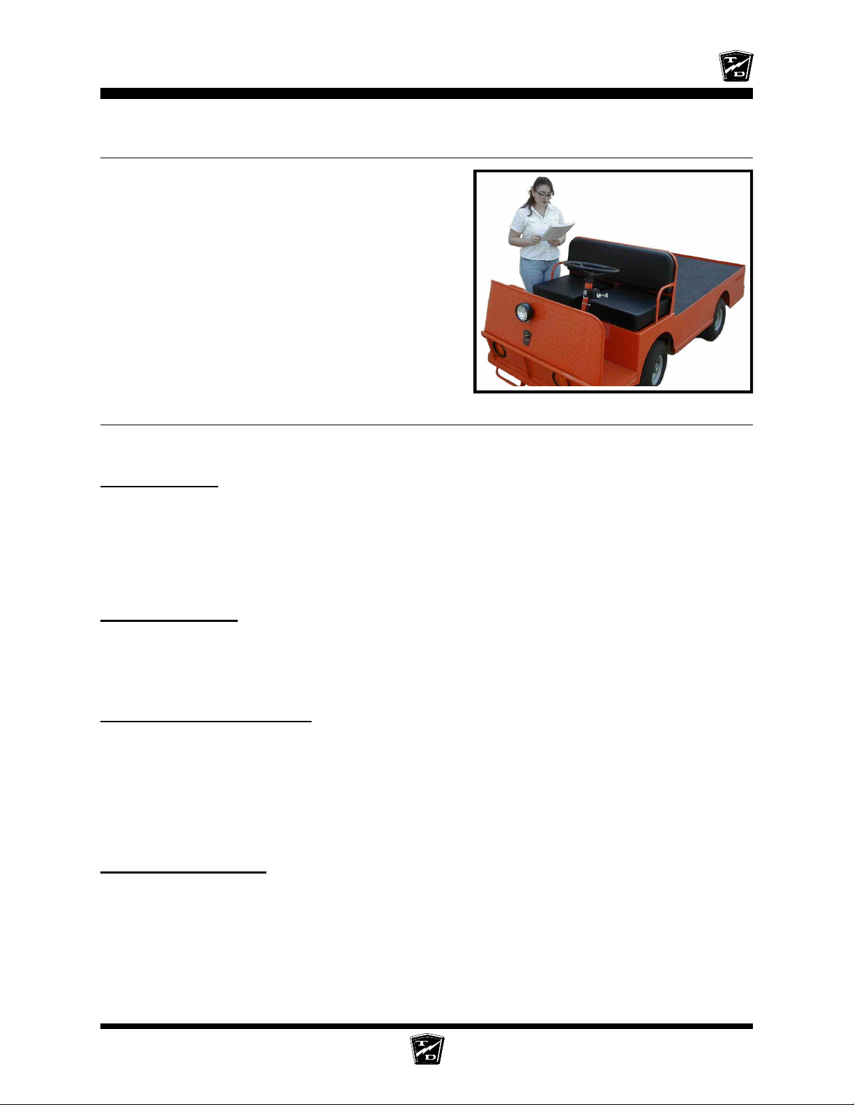
This manual is intended for use by anyone who is going
to operate, own, perform maintenance on, service, or
order parts for this Taylor-Dunn® vehicle. Each person
should be familiar with the parts of this manual that apply
to their use of this vehicle.
RESPONSIBILITIES
INTRODUCTION
Of the Owner...
The owner of this or any Taylor-Dunn® vehicle is responsible for the overall maintenance and repairs of
the vehicle, as well as the training of operators. Owners should keep a record of conducted training and
maintenance performed on the vehicle. (OSHA Regulation, 29 CFR 1910.178 Powered Industrial Truck
Operator Training).
Of the Operator...
The operator is responsible for the safe operation of the vehicle, preoperational and operational checks
on the vehicle, and the reporting of any problems to service and repair personnel.
Of the Service Personnel...
The service personnel are responsible for the service and maintenance of the vehicle. At no time
should a service person allow any untrained personnel to service or repair this or any Taylor-Dunn
vehicle. For the purposes of training, a qualified service person may oversee the repairs or services
being made to a vehicle by an individual in training. At no time should an untrained individual be
allowed to service or repair a vehicle without supervision. This manual is not a training guide.
Of the Passengers ...
®
The passengers are responsible to remain fully seated, keeping their hands, arms, and legs inside the
vehicle at all times. Each passenger should be fully aware of the vehicle’s operation. All forms of
recklessness are to be avoided. Do not engage in horseplay.
Introduction Page-3
Page 10

INTRODUCTION
HOW TO USE THIS MANUAL
This manual is organized into five main sections:
INTRODUCTION
This section describes how to use this service manual and how to identify your vehicle.
Safety Rules and Operating Instructions
This section outlines the safety and operational issues, location and operation of controls, and the
operational checks that are to be performed on this vehicle. It also includes various subjects that should
be included in the operator and service training program.
Maintenance Service and Repair
This section gives specific information on the servicing of the vehicle and a schedule for maintenance
checks.
Electrical and Charger Troubleshooting
This section identifies the troubleshooting procedures for testing the electrical system and battery charger.
Illustrated Parts
This section provides an illustrated view of various assemblies. The illustrations are accompanied by
tables identifying the parts.
Introduction Page-4
Page 11
INTRODUCTION
Conventions
Symbols and/or words that are used to define warnings, cautions, instructions, or notes found throughout
this manual:
A shaded box with the word “Warning” on its left denotes a warning.
A warning alerts the reader of a hazard that may result in injury to
or,
themselves or others. Be sure to follow any instructions contained
within a warning and exercise extreme care while performing the
task.
The symbol at the left and the bold text contained within a box
denotes a “Caution” and is used to inform the reader that property
damage may occur. Be sure to exercise special care and follow any
instructions contained with in a caution.
NOTE: Alerts the reader to additional information about a subject.
Introduction Page-5
Page 12
INTRODUCTION
HOW TO IDENTIFY YOUR VEHICLE
This manual applies to vehicles with the same model and serial numbers listed on the front cover.
These vehicles are designed for driving on smooth surfaces in and around facilities such as industrial
plants, nurseries, institutions, motels, mobile home parks, and resorts. They are not to be driven on
public highways.
This vehicle conforms to requirements for Type E vehicles as described in O.S.H.A. Standard Section
1910.178 (Powered Industrial Trucks) and with all applicable portions of the American National Standard
for Personnel and Burden Carriers (ANSI B56.8).
Theese vehicles are not designed to be driven on public roads or
highways. They are available in maximum designed speeds ranging
from 6 to 16 mph. Do not exceed the maximum designed speed.
Exceeding the maximum designed speed may result in steering
difficulty, motor damage, and/or loss of control. Do not exceed locally
imposed speed limits. Do not tow at more than 5 mph.
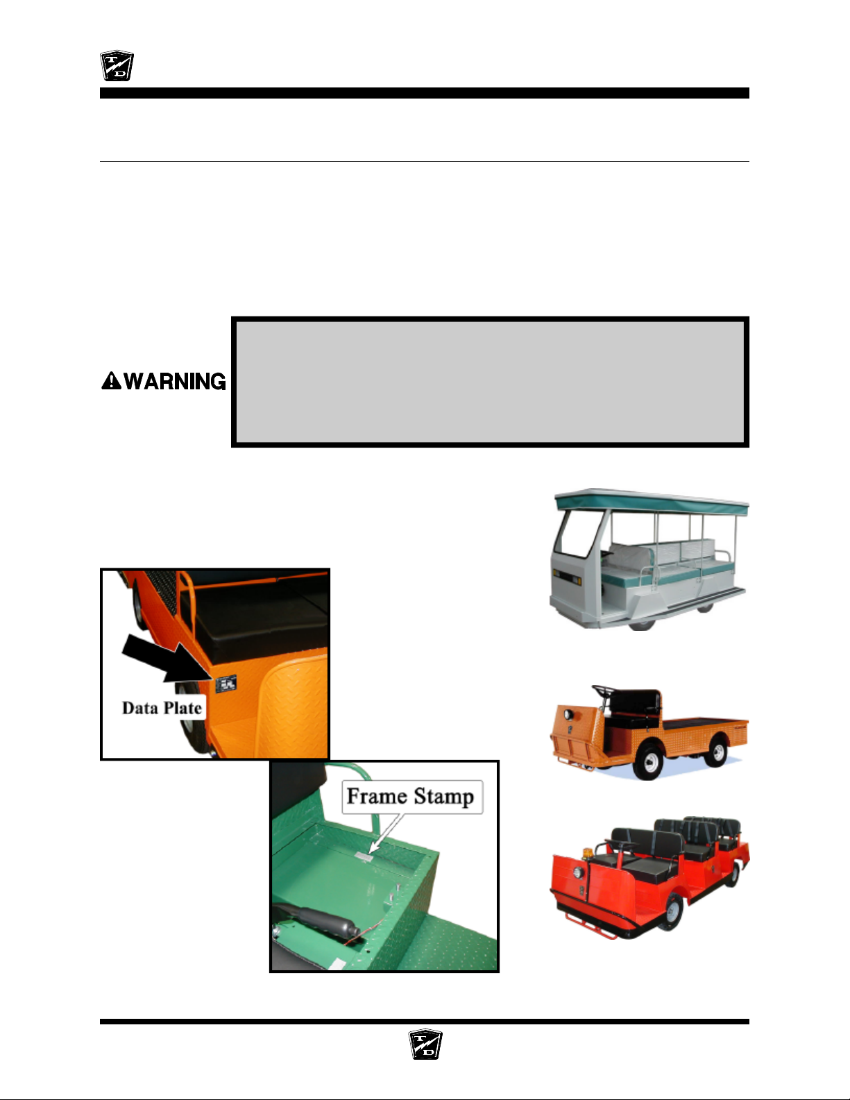
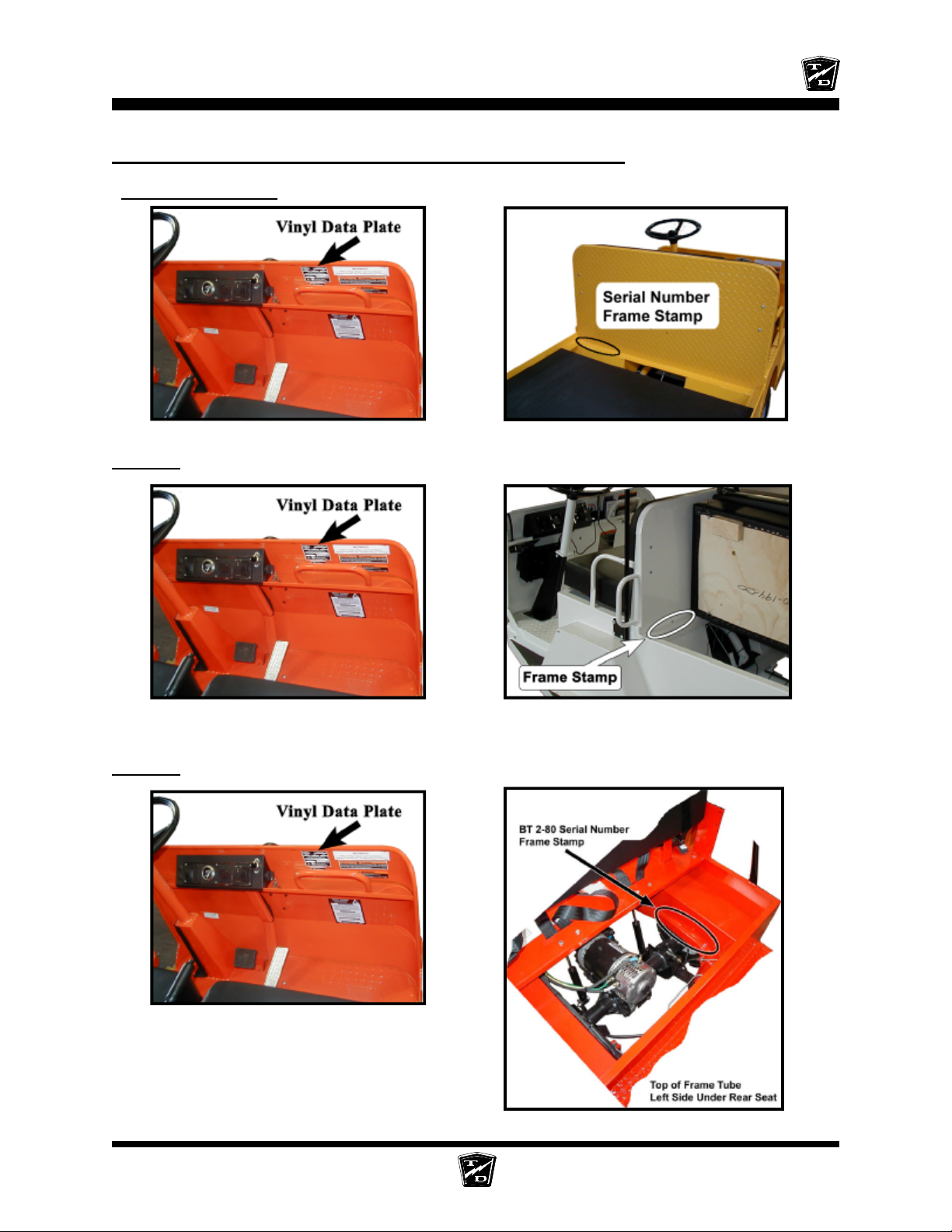
The locations of the model and serial numbers are illustrated as follows:
Starting early in 2007, the data plate and serial number fame stamp
is in the same location for all four models covered in this manual
(refer to the illustrations below). For older vehicles, the location of
the data plate and frame stamp is illustrated on the following pages.
Typical BT 2-48 shown with
optional equipment
Typical B 2-48 or B 2-54
Introduction Page-6
Typical BT 2-80 shown with
optional equipment
Page 13
INTRODUCTION
Vehicles manufactured before 2007 and up to March, 2007
B 2-48 and B 2-54
Under deck on deck rail
BT 2-48
BT 2-80
Under front left passenger cushion
Introduction Page-7
Page 14
INTRODUCTION
TAKING DELIVERY OF YOUR VEHICLE
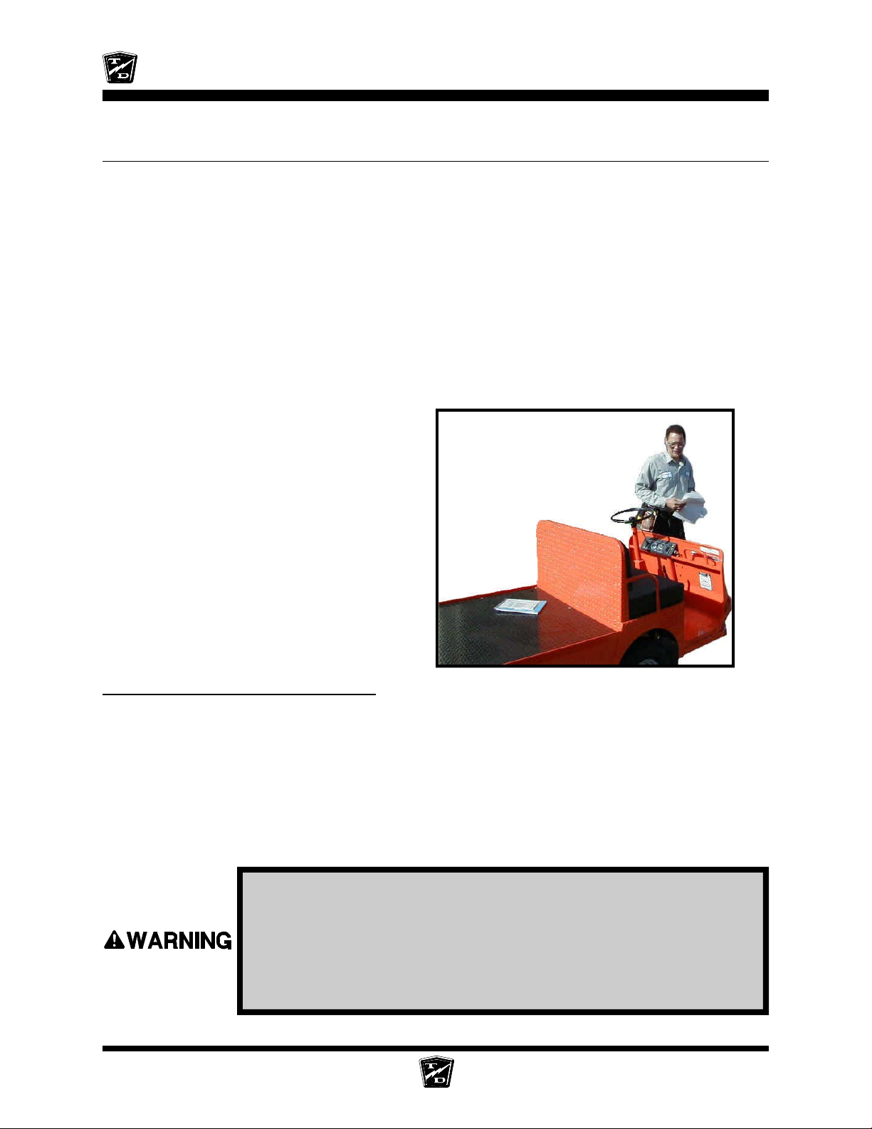
Inspect the vehicle immediately after delivery. Use the following guidelines to help identify any obvious
problems:
• Examine the contents of all packages and accessories that may have come in separate
packages with the vehicle.
• Make sure everything listed on the packing slip is there.
• Check that all wire connections, battery cables, and other electrical connections are secure.
• Check battery cells to be sure they are filled.
• Check the tire pressure, tightness of lug nuts, and for any signs of damage.
Check the operation of each of the following controls:
• Accelerator
• Brake
• Parking Brake
• Key-Switch
• Forward/Reverse Switch
• Reverse Beeper (if equipped)
• Front Headlight Switch
• Steering Wheel
• Horn
What To Do If a Problem is Found
If there is a problem or damage as a result of shipping, note the damage or problem on the bill of lading
and file a claim with the freight carrier. The claim must be filed within 48 hours of receiving the vehicle
and its accessories. Also, notify your Taylor-Dunn® dealer of the claim.
If there is a problem with the operation of the vehicle, DO NOT OPERATE THE VEHICLE. Immediately
contact your local Taylor-Dunn® distributor and report the problem. The report must be made within 24
hours of receiving the vehicle and its accessories.
The only personnel authorized to repair, modify, or adjust any part of this or any Taylor-Dunn® vehicle is
a factory authorized service technician.
The only personnel authorized to repair, modify, or adjust any part
of this or any Taylor-Dunn® vehicle is a factory authorized service
technician. Repairs made by unauthorized personnel may result in
damage to the vehicles systems which could lead to an unsafe
condition resulting in severe bodily injury and/or property damage.
Unauthorized repairs may also void the vehicles warranty.
Introduction Page-8
Page 15

TABLE OF CONTENTS
Standard Specifications* (Common)...2
Standard Specifications* (Model B 2-48/2-54) 3
Standard Specifications* (Model BT 2-48) 4
Standard Specifications* (Model BT 2-80) 5
Safety Rules and Guidelines ..............6
Driver Training Program.....................6
Driver Qualifications. .......................................... 6
Vehicle Controls ................................7
Dash up to Serial # 179669................7
1) Accessory Switch (Optional) .......................... 7
2) Headlight Switch ............................................. 7
3) Hi-Low Switch (optional) ............................... 7
4) Smart View Display ........................................ 7
5) Forward-Off-Reverse Switch .......................... 7
6) Horn Switch ..................................................... 7
7) Key-Switch ...................................................... 7
Dash Starting Serial #179670.............8
1) Headlight Switch ............................................. 8
2) Wiper Switch (Optional) ................................. 8
3) Strobe Switch (Optional) ................................ 8
4) Forward-Off-Reverse Switch .......................... 8
5) Hi-Low Switch (optional) ............................... 8
6) Smart View Display ........................................ 8
7) Horn Switch ..................................................... 8
8) Key-Switch ...................................................... 8
Directional Signals (Optional) ............................ 9
Steering ................................................................. 9
Hazard Light Switch (Optional) ......................... 9
Accelerator Pedal ................................................. 9
Foot Brake Pedal .................................................. 9
Charger Interlock ................................................. 10
Seat Interlock Switch ........................................... 10
Electrolyte Alarm (Optional) ............................... 10
Park Brake ............................................................ 10
Trailer Brake Module (optional) ......................... 11
Smart View Display ............................................. 12
Fault Code Tables ................................................ 14
Vehicle Operation Guidelines .............15
Safety Guidelines ................................................. 15
Starting: ................................................................ 15
While driving: ...................................................... 15
Loading and Unloading ....................................... 15
Towing Loads: ...................................................... 15
Parking .................................................................. 16
Automatic Electric Park Brake ........................... 16
Towing This Vehicle ............................................ 16
Dump Bed (optional)..........................17
Operation .............................................................. 17
Service .................................................................. 17
Lowering the Dump Manually ............................ 18
Lubrication ........................................................... 18
Hydraulic Pump Exploded View..........19
Charging your vehicle ........................20
Signet Charger Operation, Model HB Series ..... 20
Signet Charger Operation, Model HBS series ... 20
Lestronic II® Charger Operation ........................ 21
New Battery Break in .......................................... 21
Charging Time ...................................................... 21
Storing / Returning to Service............21
Storing Your Vehicle ............................................ 21
Returning to Service ............................................ 21
Periodic Maintenance Checklist .........22
Standard Periodic Maintenance Schedule
for the Smart View Display .............23
Daily Visual inspection: ...................................... 24
Maintenance Guidelines for
Severe Duty Applications ...............24
Safety Rules and
Operating Instructions
Page 16
SAFETY RULES AND OPERATING INSTRUCTIONS
Page 2
STANDARD SPECIFICATIONS* (COMMON)
ITEM VOLTAGE SPECIFICATION
Min/Max Battery 169 kg to 261 kg (372 lbs to 576 lbs)
Weights
Transmission Helical Gear, Oil Bath, Automotive Type Hypoid
Brakes Rear Wheel Hydraulic Disc, Hand Operated Park Brake, or
Steering Automotive Steering 24:1
Frame Steel Unitized Body, Heavy Duty 16 Gauge Steel,
Instrumentation Smart View Display (Battery Status Indicator, Hour
Light Accessories Headlight, Dual Tail/Brake Lights
Charger 36 Volt 115v AC/12A, 60Hz, 25 Amp DC, Built-In, Automatic
48 Volt 115v AC/15A, 60Hz, 25 Amp DC, Built-In, Automatic
Differential
Optional 4 Wheel Hydraulic Disc, Hand Operated Park
Brake
Diamond Plate
Meter, System Status Monitor), Key Switch, Horn Button,
Forward/Reverse Switch, Headlight Switch
These vehicles conform to requirements for Type E vehicles as described in O.S.H.A. Standard Section
1910.178 (Powered Industrial Trucks) and with all applicable portions of the American National Standard for
Personnel and Burden Carriers (ANSI B56.8).
* - Specifications are subject to change without notice.
Safety Rules
Page 17

SAFETY RULES AND OPERATING INSTRUCTIONS
Page 3
STANDARD SPECIFICA TIONS* (MODEL B 2-48/2-54)
ITEM MODEL VOLTAGE SPECIFICATION
Occupancy B 2-48, B 2-54 2 Passenger
Electrical System B 2-48 36 Volt 6-217 Amp Hour, 6 Volt, Lead Acid Batteries,
B 2-48 48 Volt 8-250 Amp Hour, 6 Volt, Lead Acid Batteries,
B 2-54 36 Volt 6-217 Amp Hour, 6 Volt, Lead Acid Batteries,
Dimensions B 2-48, B 2-54 307 L X 114 W X 114 H Centimeters
Deck dimensions 104.4 W x 191 L Centimeters (41.25 W x 75.25 L Inches)
Turning Radius B 2-48, B 2-54 350 Centimeters (138 Inches)
Tires B 2-48 5.70 x 8 Load Range B
B 2-54 18 x 5 x 14 Solid Extra Cushion
Dry Weight B 2-48 542 kg (1194 lbs)
Without Batteries B 2-54 693 kg (1528 lbs)
Maximum Load B 2-48 1360 kg (3000 lbs)
B 2-54 2268 kg (5000 lbs)
Motor, DC B 2-48 36 Volt 3.2 kW, (4.4 hp) for 60 min, 5.1 kW, (6.9 hp) for 5 min
Separately Excited B 2-48 48 Volt 4.4 kW, (5.9 hp) for 60 min, 7.2 kW, (9.6 hp) for 5 min
Field B 2-54 36 Volt 4.5 kW, (6.0 hp) for 60 min, 8.6 kW, (11.5 hp) for 5 min
Solid State Speed Control, 400 Amp
Solid State Speed Control, 400 Amp
Solid State Speed Control, 500 Amp
121 L X 45 X 45 H Inches
These vehicles conform to requirements for Type E vehicles as described in O.S.H.A. Standard Section
1910.178 (Powered Industrial Trucks) and with all applicable portions of the American National Standard for
Personnel and Burden Carriers (ANSI B56.8).
* - Specifications are subject to change without notice.
Safety Rules
Page 18
SAFETY RULES AND OPERATING INSTRUCTIONS
Page 4
STANDARD SPECIFICA TIONS* (MODEL BT 2-48)
ITEM VOLTAGE SPECIFICATION
Occupancy 10
Electrical System 36 Volt Six 217 Amp Hour, 6 Volt, Lead Acid Batteries,
48 Volt Eight 250 Amp Hour, 6 Volt, Lead Acid Batteries,
Dimensions 307L X 162W X 117H Centimeters
Turning Radius 363 Centimeters (143 Inches)
Tires 5.70 x 8 Load Range B
Dry Weight 695 kg (1,533 lbs)
Without Batteries
Maximum Load 1360 kg (3,000 lbs)
Motor, DC 36 Volt 4.5 kW, (6.0 Horse Power) for 60 min
Separately Excited Field 8.6 kW, (11.5 Horse Power) for 5 min
48 Volt 6.0 kW, (8.0 Horse Power) for 60 min
Solid State Speed Control, 500 Amp
Solid State Speed Control, 500 Amp
121L X 64X 46H Inches
12.2 kW, (16.3 Horse Power) for 5 min
These vehicles conform to requirements for Type E vehicles as described in O.S.H.A. Standard Section
1910.178 (Powered Industrial Trucks) and with all applicable portions of the American National Standard for
Personnel and Burden Carriers (ANSI B56.8).
* - Specifications are subject to change without notice.
Safety Rules
Page 19

SAFETY RULES AND OPERATING INSTRUCTIONS
Page 5
STANDARD SPECIFICA TIONS* (MODEL BT 2-80)
ITEM VOLTAGE SPECIFICATION
Occupancy Eight
Electrical System 36 Volt Six 217 Amp Hour, 6 Volt, Lead Acid Batteries,
48 Volt Eight 250 Amp Hour, 6 Volt, Lead Acid Batteries,
Dimensions 330 L X 127 W X 112 H Centimeters
Turning Radius 406 Centimeters (160 Inches)
Tires 5.70 x 8 Load Range B
Dry Weight 503 kg (1,110 lbs)
Without Batteries
Maximum Load 1,361 kg (3,000 lbs)
Motor, DC 36 Volt 4.5 kW, (6.0 Horse Power) for 60 min
Separately Excited Field 8.6 kW, (11.5 Horse Power) for 5 min
48 Volt 6.0 kW, (8.0 Horse Power) for 60 min
Solid State Speed Control, 500 Amp
Solid State Speed Control, 500 Amp
130 L X 50 X 44 H Inches
12.2 kW, (16.3 Horse Power) for 5 min
These vehicles conform to requirements for Type E vehicles as described in O.S.H.A. Standard Section
1910.178 (Powered Industrial Trucks) and with all applicable portions of the American National Standard for
Personnel and Burden Carriers (ANSI B56.8).
* - Specifications are subject to change without notice.
Safety Rules
Page 20
SAFETY RULES AND OPERATING INSTRUCTIONS
Page 6
SAFETY RULES AND
GUIDELINES
It is the responsibility of the owner of this vehicle to assure
that the operator understands the various controls and
operating characteristics of this vehicle (extracted from
the American National Standards Institute Personnel and
Burden Carriers ANSI B56.8). As well as, following the
safety rules and guidelines outlined in ANSI B56.8 and
listed below.
These vehicles are designed for driving on smooth
surfaces in and around facilities such as industrial plants,
nurseries, institutions, motels, mobile home parks, and
resorts. They are not to be driven on public highways.
These vehicles are not designed to be
driven on public roads or highways. They
are available in maximum designed speeds
ranging from 6 to 16 mph. Do not exceed
the maximum designed speed. Exceeding
the maximum designed speed may result
in steering difficulty, motor damage, and/
or loss of control. Do not exceed locally
imposed speed limits. Do not tow this
vehicle at more than 5 mph.
Refer to Vehicle Operational Guidelines, Safety
Guidelines section for important safety information
regarding operating this vehicle.
DRIVER TRAINING PROGRAM
According to ANSI B56.8, the owner of this vehicle shall
conduct an Operator Training program for all those who
will be operating this vehicle. The training program shall
not be condensed for those claiming to have previous
vehicle operation experience. Successful completion of
the Operator Training program shall be required for all
personnel who operate this vehicle.
The Operator Training program shall include the
following:
• Operation of this vehicle under circumstances
normally associated with your particular environment.
• Emphasis on the safety of cargo and personnel.
• All safety rules contained within this manual.
• Proper operation of all vehicle controls.
• A vehicle operation and driving test.
Driver Qualifications.
Only those who have successfully completed the
Operator Training program are authorized to drive this
vehicle. Operators must possess the visual, auditory,
physical, and mental ability to safely operate this vehicle
as specified in the American National Standards Institute
Controlled Personnel and Burden Carriers ANSI B56.8.
The following are minimum requirements necessary to
qualify as an operator of this vehicle:
Read and follow all of the guidelines listed
below. Failure to follow these guidelines
may result in severe bodily injury and/or
property damage.
Before working
on a vehicle:
1. Make sure the key-switch is in the “OFF”
position, then remove the key.
2. Place the forward-reverse switch in the
center “OFF” position.
3. Set the park brake.
4. Place blocks under the front wheels to
prevent vehicle movement.
5. Disconnect the main positive and
negative cables at the batteries.
• Demonstrate a working knowledge of each control.
• Understand all safety rules and guidelines as
presented in this manual.
• Know how to properly load and unload cargo.
• Know how to properly park this vehicle.
• Recognize an improperly maintained vehicle.
• Demonstrate ability to handle this vehicle in all
conditions.
Safety Rules
Page 21
SAFETY RULES AND OPERATING INSTRUCTIONS
Page 7
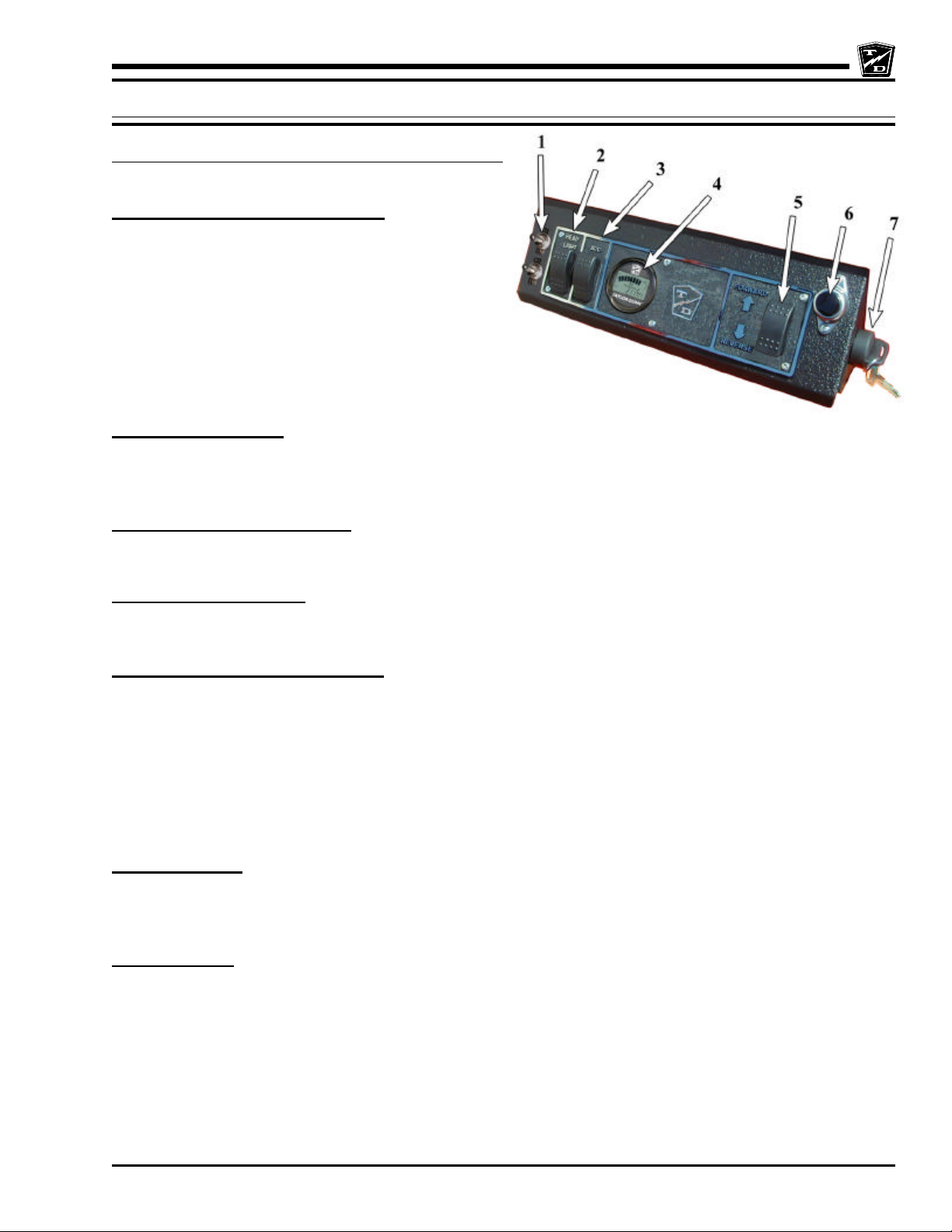
VEHICLE CONTROLS
DASH UP TO SERIAL # 179669
1) Accessory Switch (Optional)
The accessory switch is located on the left side of the
instrument panel and to the right of the headlight switch.
Push the top of the switch to turn on the accessory. Push
the bottom of switch to turn off the accessory. The
accessory can be turned on with the key switch in the
“OFF” position. If a vehicle is equipped with windshield
wipers and one or more accessories, the windshield
wipers are controlled from this switch. Other accessories
are controlled from the auxiliary switch.
2) Headlight Switch
The headlight switch is located on the top left of the instrument panel. Push the right side of the
switch to turn the lights on. Push the left side of the switch to turn the light off.
3) Hi-Low Switch (optional)
The high-low switch is located on the lower left of the instrument panel. Toggle the switch lever up for normal speed.
Toggle the switch lever down for slow speed.
4) Smart View Display
Refer to details later in this chapter.
5) Forward-Off-Reverse Switch
The forward-off-reverse switch, located on the right side of the instrument panel, determines the direction of travel of
the vehicle. Push the top of the switch to engage the forward direction. Push the bottom of the switch to engage the
reverse direction.
DO NOT SWITCH from forward to reverse or vice-versa while the vehicle is in motion. Make sure the vehicle is
completely stopped before shifting.
The forward-off-reverse switch should be in the center “OFF” position, with the key-switch off and the park brake set
whenever the operator leaves the vehicle.
6) Horn Switch
The horn switch is located on the right side of the instrument panel. Depress the switch to sound the horn, release it
to turn it off.
7) Key-Switch
A key-switch, located on the right center side of the instrument panel, turns on the vehicle. Rotate the key clockwise
to turn the vehicle power on, counterclockwise to turn the vehicle power off.
The key-switch should be in the “OFF” position whenever the operator leaves the vehicle.
This switch is also designed to secure and disable the vehicle. The key can only be removed when the key-switch is
in the “OFF” position.
Safety Rules
Page 22
SAFETY RULES AND OPERATING INSTRUCTIONS
Page 8
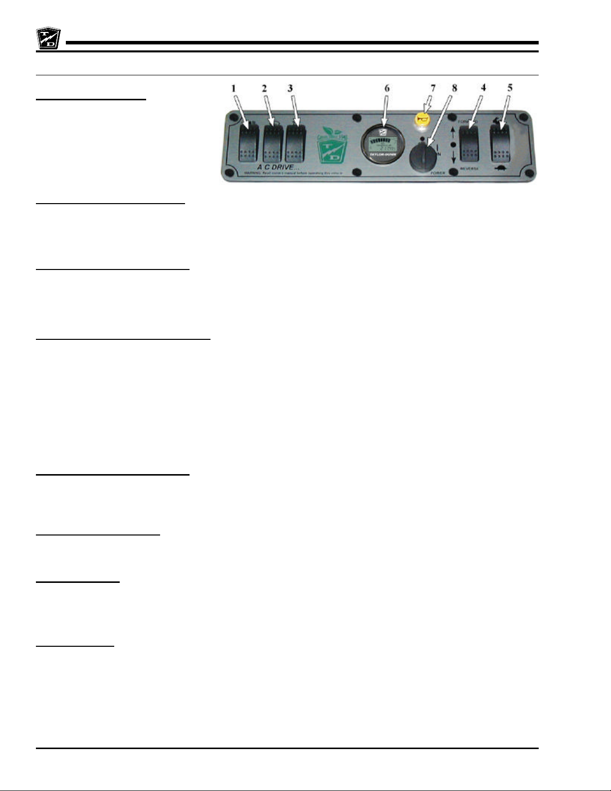
DASH STARTING SERIAL #179670
1) Headlight Switch
The headlight switch is located on the top
left of the instrument panel. Push the right
side of the switch to turn the lights on.
Push the left side of the switch to turn
the light off.
2) Wiper Switch (Optional)
The wiper switch is located on the left side of the instrument panel and to the right of the headlight switch. Push the top
of the switch to turn on the wiper. Push the bottom of switch to turn off the wiper. The wiper can be turned on with the
key switch in the “OFF” position.
3) Strobe Switch (Optional)
The strobe switch is located on the left side of the instrument panel and to the right of the wiper switch. Push the top
of the switch to turn on the strobe. Push the bottom of switch to turn off the strobe. The strobe can be turned on with
the key switch in the “OFF” position.
4) Forward-Off-Reverse Switch
The forward-off-reverse switch, located on the right side of the instrument panel, determines the direction of travel of
the vehicle. Push the top of the switch to engage the forward direction. Push the bottom of the switch to engage the
reverse direction.
DO NOT SWITCH from forward to reverse or vice-versa while the vehicle is in motion. Make sure the vehicle is
completely stopped before shifting.
The forward-off-reverse switch should be in the center “OFF” position, with the key-switch off and the park brake set
whenever the operator leaves the vehicle.
5) Hi-Low Switch (optional)
The high-low switch is located on the lower left of the instrument panel. Toggle the switch lever up for normal speed.
Toggle the switch lever down for slow speed.
6) Smart View Display
Refer to details later in this chapter.
7) Horn Switch
The horn switch is located on the right side of the instrument panel. Depress the switch to sound the horn, release it
to turn it off.
8) Key-Switch
A key-switch, located on the right center side of the instrument panel, turns on the vehicle. Rotate the key clockwise
to turn the vehicle power on, counterclockwise to turn the vehicle power off.
The key-switch should be in the “OFF” position whenever the operator leaves the vehicle.
This switch is also designed to secure and disable the vehicle. The key can only be removed when the key-switch is
in the “OFF” position.
Safety Rules
Page 23
SAFETY RULES AND OPERATING INSTRUCTIONS
Page 9
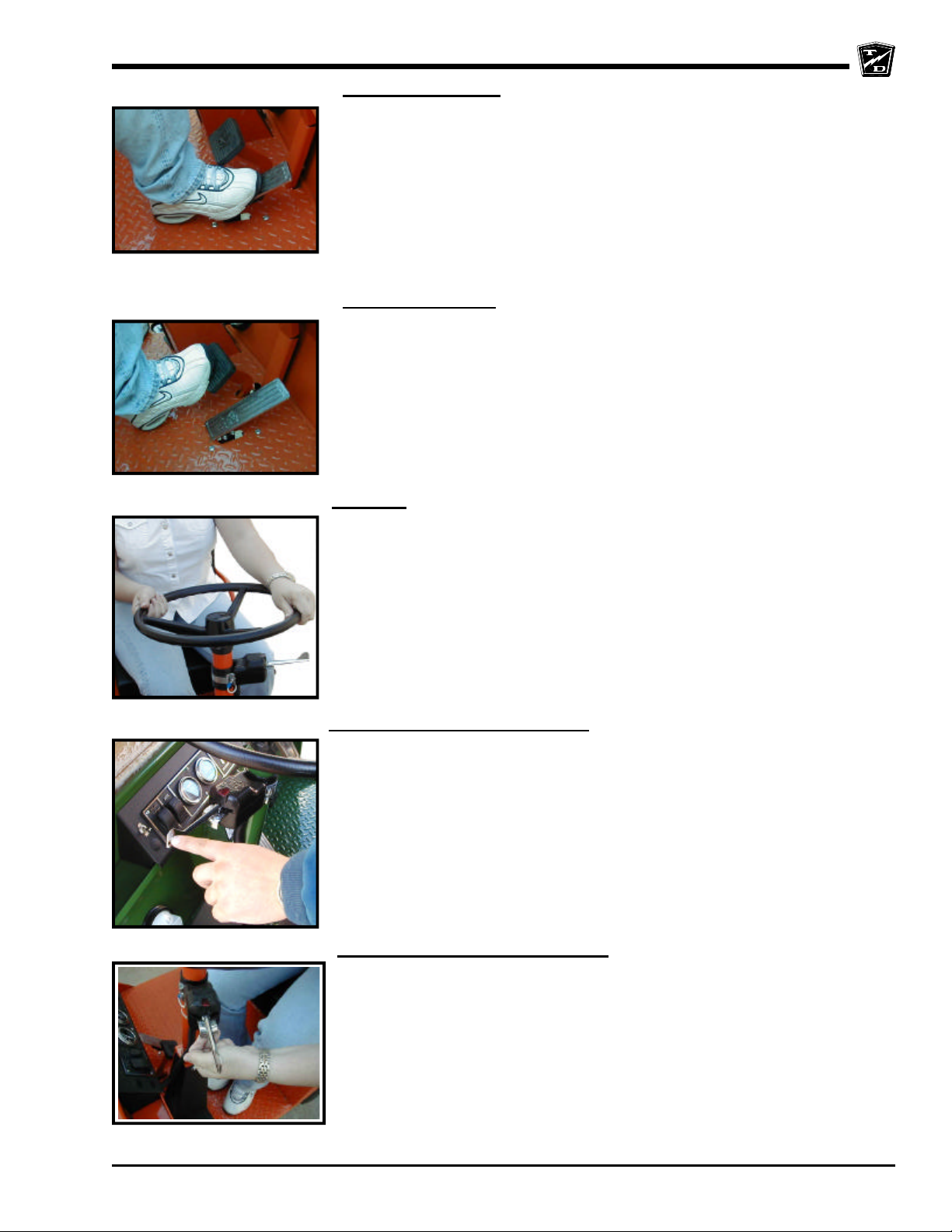
Accelerator Pedal
The accelerator pedal is located to the right of the brake pedal. It controls the
speed of the vehicle and operates similar to the accelerator pedal in an
automobile. Depress the pedal to increase speed and release the pedal to
decrease speed.
Foot Brake Pedal
The foot brake pedal, is located to the right of the steering column, it is for
operation with the right foot only. It works similar to the brake in an automobile.
Applying pressure to the brake pedal slows the vehicle according to the amount
of pressure applied. Relieving pressure from the pedal releases the braking
action.
Steering
The steering wheel and steering system are similar to an automobile. To turn
right, turn the steering wheel clockwise. To turn left, turn the steering wheel
counter-clockwise. If equipped with tilt steering, the release lever is located
on the lower left of the steering column. Pull the lever up to reposition the
steering wheel.
Directional Signals (Optional)
The turn signal lever is located on the left side of the steering column. Push
the lever forward to activate the right turn signal and pull the lever back to
activate the left turn signal.
Hazard Light Switch (Optional)
The hazard light switch is located on the left side of the steering column. The
switch is a small tab. To activate the hazard lights, pull the tab out. To turn
the hazard lights off, push forward or pull back the directional signal lever.
Safety Rules
Page 24
SAFETY RULES AND OPERATING INSTRUCTIONS
Page 10
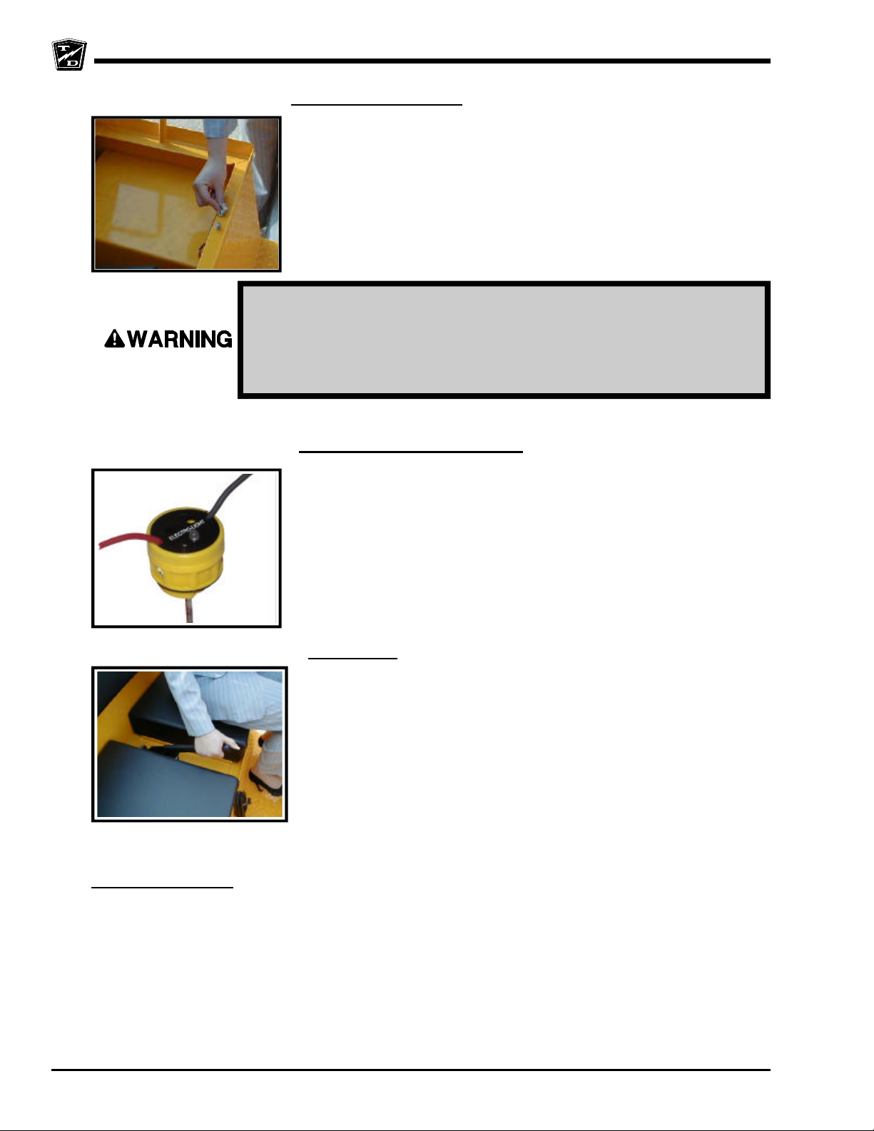
Seat Interlock Switch
A switch located under the driver's seat disables the power to the vehicle
when the driver leaves the seat. The driver must be seated for the vehicle to
operate.
Whenever the driver leaves the vehicle, the driver should turn the key-switch
off, place the forward-off-reverse switch in the center “OFF” position, and set
the park brake.
The seat interlock switch is only one part of the vehicle safety system.
The interlock switch should not be relied upon as the only safety
feature used to disable or disengage this vehicle. Doing so could result
in unexpected movement of the vehicle causing severe bodily injury
and/or property damage.
Electrolyte Alarm (Optional)
Charger Interlock
The Electrolyte Alarm is located in the battery area, in the 4th battery cell from
the main battery positive cable. The Electrolyte alarm is activated when the
battery cell fluid level falls below the level of the probe. The alarm is an audible
continuous sound along with a bi-color indicator lamp. Inspect the fluid level in
all battery cells when the alarm sounds or the bi-color lamp turns from its green
color to red. The vehicle batteries should then be filled and/or charged. With
the fluid level at a normal operating level and/or the batteries charged the alarm
and light will reset.
Park Brake
The parking brake is actuated with a hand lever, which is located to the right
of the driver. To set the parking brake, push down on the brake pedal and
pull the lever up until it locks. To release the park brake, depress the foot
brake pedal, pull up on the park brake handle, push the release button, and
lower the handle.
The charger interlock is designed to disable the vehicle from being driven while the AC charger cord is
plugged into a functioning power source.
Safety Rules
Page 25
SAFETY RULES AND OPERATING INSTRUCTIONS
Page 11
Trailer Brake Module (optional)
The trailer brake module controls the braking functions of a trailer equipped with electric brakes. There have
been many styles of brake modules used. All of the brake modules that have been used function the same
other than that the location of the manual adjustment controls may vary.
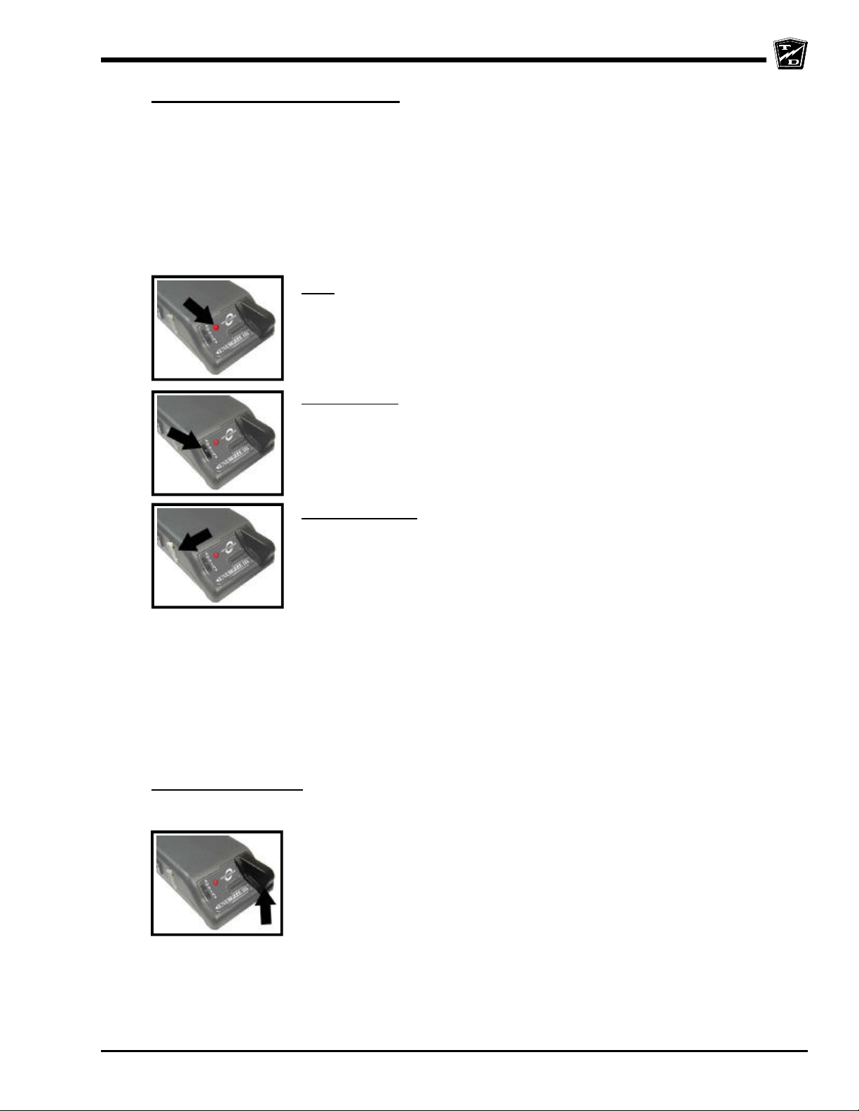
The brake module will be located under the dash tray to the left of the steering column. It has a red indicator
light (LED), a Thumb wheel braking force adjustor, a Pendulum level adjustment lever, and a Manual
Braking lever.
As the vehicle slows during braking, the brake module sends a signal to the trailer energizing the trailer
brakes. This signal is proportional depending on how fast the vehicle is stopping.
LED: The LED’s brightness is related to the braking force
at the trailer, dim with little or no signal to bright at maximum
braking force. Once the vehicles has stopped, the LED
will remain at it’s dimmest intensity as long as the brake
pedal is depressed.
Thumb wheel: The thumb wheel is used to adjust how
much braking force is sent to the trailer brakes. Rotate the
thumb wheel upward towards the top of the housing to
increase the braking force.
Pendulum Lever: The brake sensor inside the module
must be level for it to function correctly. The pendulum
lever is used to level the internal brake sensor. Perform
the following steps to adjust the sensor:
1 This adjustment must be done with the trailer disconnected from the vehicle.
2 Stop the vehicle on a level surface but do not release the brake pedal.
3 Adjust the thumb wheel to its minimum position downward towards the bottom of the module case.
4 Pull the pendulum towards the front of the module case. The LED should be at it’s maximum intensity.
5 Slowly push the pendulum towards the rear of the module case and stop when the LED just reaches
its minimum intensity. The pendulum should be very close to vertical.
6 Repeat the previous two steps a few times to be sure that the pendulum is at the correct position.
Manual Braking Lever: The manual braking lever can be used to manually apply the trailer brakes. Slide
the lever to the left to apply the brakes. The braking force is proportional depending on how far the lever is
moved.
Safety Rules
Page 26
SAFETY RULES AND OPERATING INSTRUCTIONS
Page 12
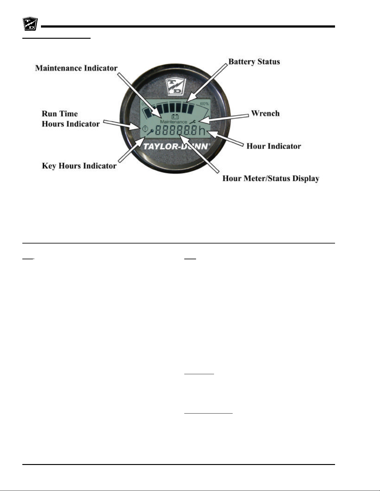
Smart View Display
The Smart View Display (SVD) functions as a Battery Status Indicator (BSI), Hour Meter (HM), speed controller
status monitor, and as an optional maintenance monitor feature. The operation of each of these functions is described
below.
BSI: A bar graph representing the current state of charge
is located across the top of the display. When the
batteries are fully charged, all segments of the bar graph
will be on. As the batteries are used, segments will turn
off in the order of right to left.
When the batteries are discharged to 75%, the last three
segments will flash indicating that you are approaching
the end of the battery cycle. At this time, the vehicle’s
batteries should be charged as soon as possible.
At 90%, all segments will flash and the vehicles speed
will be reduced. At this time, the vehicle should be
removed from service for charging. Discharging beyond
90% will result in damage to the batteries that will shorten
the battery life-span.
NOTE: The battery status gauge as well as any faults
indicating low battery voltage will not reset
until the batteries have successfully
completed a charging cycle.
HM: Depending on the revision level of the controller,
there are one or two hour meter functions, Key Hours
and Run Time Hours (see note below).
Key Hours is the accumulated length of time in hours
that the key switch is in the “ON” position.
Run Time Hours is the accumulated length of time that
the vehicles has been in operation. Time is accumulated
when the FS-1 switch in the accelerator module is closed.
One of the Hours functions is being displayed whenever
the either of the Hours Indicators are visible at the right
side of the display.
NOTE: The Key Hours function was discontinued
starting with revision K controllers shipped
in 2007.
Key Hours: When the display is turned on, the Key Hours
will be displayed for approximately 5-seconds as
indicated by the Key Hours Indicator located at the lower
left of the display. The icon represents the silhouette of
a key.
Run Time Hours: After the initial 5-seconds, the Run
Time Hours will be displayed as indicated by the Run
Time Hours Indicator located at the left of the display.
The icon represents a motor symbol with a “T” in the
center.
Safety Rules
Page 27
SAFETY RULES AND OPERATING INSTRUCTIONS
Page 13
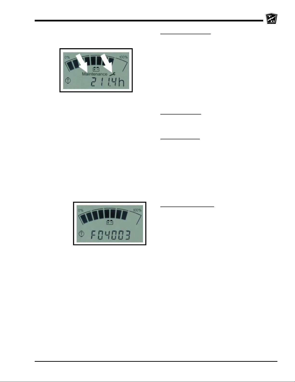
Display showing Maintenance and
Wrench icons
Maintenance Monitor:
NOTE: The Maintenance Monitor function is optional.
The Maintenance Monitor function can be
turned ON or OFF by your dealer.
Operation: The SMD notifies the operator 10-hours
(standard) before a scheduled maintenance is due.
During this warning period, the meter will continue to
alert the operator. This should allow sufficient time for
the operator to schedule the maintenance that is due,
with minimal down time. If the scheduled maintenance
is not performed before the warning period elapses, then
the vehicles maximum speed will be significantly
reduced.
Warning period: The warning starts when the
Maintenance Indicator is ON and the Wrench icon is
flashing. The Wrench icon will continue to flash until the
warning time has expired.
Maintenance Due: Once the warning has expired and
the maintenance is due, the Wrench icon will stop
flashing and remain ON. Additionally, the vehicles
maximum speed will be significantly reduced until the
maintenance is performed and the display is reset. The
display should only be reset by an authorized technician.
Refer to the Illustrated parts section for information
regarding tools required to reset the Smart View Display.
Speed controller status: The display will indicate a fault
code whenever the control system logic detects a
problem with the control system. A fault code is being
displayed whenever the Fault Code Indicator (the letter
‘F’) is visible at the left of the numeric display. Refer to
the fault code table in this section for a summery
description of the fault codes.
Safety Rules
Page 28

SAFETY RULES AND OPERATING INSTRUCTIONS
Page 14
Fault Code Tables
NOTE: Most faults are a result of a fault in the control
system that will require service by a qualified
technician. These faults are shown here for
reference only.
Operator correctable faults are shown in
bold and underlined.
Level 1 Faults
Fault Code Description What to do
F01000 P/S Motor Overheated Stop the vehicle and allow
the system to cool down.
F01001 Motor Brush Fault Refer to service technician
F01002 Pump Motor Brush Fault Refer to service technician
F01003 P/S motor Brush Fault Refer to service technician
F01004 Low Battery Volts Batteries are empty and
require charging. If this
fault does not reset after the
charge cycle is complete
then there may be a
problem with the charger or
batteries.
Refer to qualified service
technician.
F01005 Controller Overheated Stop the vehicle and allow
the system to cool. This
could be a result of an
overloaded vehicle.
F01006 Traction Motor Hot Stop the vehicle and allow
the system to cool down.
This could be a result of an
overloaded vehicle
F01007 Pump Motor Overheated Stop the vehicle and allow
the system to cool down.
F01008 Wiring fault Refer to service technician
Level 4 Faults
Fault Code Description What to do
F04000 Open Contactor Refer to service technician
F04001 Contactor Welded Refer to service technician
F04002 Steer POT Fault N/A
F04003 Sequence Fault Start up switches were not
operated in the correct
order. Refer to Vehicle
Operation Guidelines for
correct sequence.
F04004 F&R Fault Refer to service technician
F04005 F&R Fault Direction was selected
before start switch was
closed. Place direction
selector in the OFF position
and restart.
F04006 Interlock Fault Seat or foot interlock switch
not closed.
F04007 Inch Switch Fault F&R switch NOT in neutral.
F04008 Steer Fault Refer to service technician
F04009 Low Battery Volts Extreme low battery voltage
at the controller. May be a
result of severely
discharged battery or
wrong battery installed.
Confirm that the correct
battery is installed and
charge the battery.
F04010 High battery Volts Refer to service technician
F04011 Out of Range Fault Refer to service technician
F04012 CRC Fault Refer to service technician
F04013 Capacitor Fault Refer to service technician
Level 5 Faults
Fault Code Description What to do
F05000 Contactor Over Current Refer to service technician
F05001 Controller Fault Refer to service technician
F05002 Configuration Error Refer to service technician
F05003 Internal Fault Refer to service technician
F05004 VA Fail Refer to service technician
F05005 Data Layer Fault Refer to service technician
F05006 MOSFET Short Refer to service technician
F05007 Power Up Fault Refer to service technician
F05008 Line Contactor Short Refer to service technician
F05009 Wiring/Motor Short Refer to service technician
F05010 Power Up Fault Refer to service technician
F05011 Drive 0 ON Refer to service technician
F05012 Drive 1 ON Refer to service technician
F05013 Drive 0 OFF Refer to service technician
F05014 Drive 1 OFF Refer to service technician
F05015 Drv 0 MOSFET Trip Refer to service technician
F05016 Drv 1 MOSFET Trip Refer to service technician
F05017 Traction ON Refer to service technician
F05018 Traction OFF Refer to service technician
F05019 MOSFET Short_L Refer to service technician
F05020 Power Up Fault Refer to service technician
F05021 Traction Welded Refer to service technician
F05022 Traction MOSFET Refer to service technician
F05023 Auto Zero Refer to service technician
F05024 Drive 0 ON L Refer to service technician
F05025 Drive 1 ON L Refer to service technician
F05026 Drive 0 OFF L Refer to service technician
F05027 Drive 1 OFF L Refer to service technician
F05028 0 MOSFET trip L Refer to service technician
F05029 1 MOSFET trip L Refer to service technician
F05030 Traction ON L Refer to service technician
F05031 Traction OFF L Refer to service technician
F05032 MOSFET Short R Refer to service technician
F05033 Power Up Fault Refer to service technician
F05034 Traction Welded Refer to service technician
F05035 Traction MOSFET Refer to service technician
F05036 Auto Zero R Refer to service technician
F05037 Drive 0 ON R Refer to service technician
F05038 Drive 1 On R Refer to service technician
F05039 Drive 0 OFF R Refer to service technician
F05040 Drive 1 OFF R Refer to service technician
F05041 0 MOSFET Trip R Refer to service technician
F05042 1 MOSFET Trip R Refer to service technician
F05043 Traction ON R Refer to service technician
F05044 Traction OFF R Refer to service technician
F05045 Stack Corrupt Refer to service technician
F05046 Open Contactor Refer to service technician
Level 2 Faults
Fault Code Description What to do
F02000 Throttle Fault Occurs if throttle control
F02001 Throttle Fault
F02002 Belly Switch Fault Refer to service technician
F02003 Open Field Refer to service technician
F02004 Open Field L Refer to service technician
F02005 Open Field R Refer to service technician
voltage is high at start
up indicating that the
throttle pedal was
depressed when the
start switch was closed.
If the pedal was not
depressed, then refer to
qualified service
technician.
Safety Rules
Page 29

SAFETY RULES AND OPERATING INSTRUCTIONS
Page 15
VEHICLE OPERATION GUIDELINES
Safety Guidelines
• Only qualified and trained operators may drive this
vehicle.
• Drive only on level surfaces or on surfaces having
an incline of no more than 10% (5.6 degrees).
• Drive slowly when making a turn, especially if the
ground is wet or when driving on an incline.
• This vehicle may overturn easily if turned sharply or
when driven at high speeds.
• Observe all traffic regulations and speed limits.
• Keep all body parts (head, arms, legs) inside this
vehicle while it is moving.
• Keep the vehicle under control at all times.
• Yield right of way to pedestrians, ambulances, fire
trucks, or other vehicles in emergencies.
• Do not overtake another vehicle at intersections, blind
spots, or other dangerous locations.
• Do not drive over loose objects, holes, or bumps.
• Yield right of way to pedestrians and emergencies
vehicles.
• Stay in your driving lane under normal conditions,
maintaining a safe distance from all objects.
• Keep a clear view ahead at all times.
While driving:
• Slow down and sound the horn to warn pedestrians
or when approaching a corner or other intersection.
• No reckless driving.
• Do not drive this vehicle on steep inclines or where
prohibited.
• Immediately report any accidents or vehicle problems
to a supervisor.
NOTE: This vehicle is equipped with regenerative
motor braking. When the throttle pedal is
released, the motor is converted into a
generator. This will slow the vehicle and
return this energy to the battery. To disable
the motor braking action and allow the vehicle
to coast, hold slight pressure on the throttle
pedal.
NOTE: If the operator leaves the driver seat while in
motion, the vehicle will come to an abrupt
stop.
Loading and Unloading
• Do not carry more than the maximum number of
passengers allowed for this vehicle.
• Do not exceed the cargo load capacity.
• Do not load cargo that can fall off.
Starting:
Perform all necessary vehicle preparation steps,
inspections, or maintenance before operating this
vehicle.
NOTE: The vehicle is equipped with a seat or foot
interlock switch. This switch must be closed
BEFORE the throttle is depressed.
1. Make sure the forward-off-reverse switch is in the
center “OFF” position.
2. If equipped with a manual park brake, set the
parking brake.
3. Hold down the foot brake.
4. Rotate the ON-OFF switch to the “ON” position.
5. Wait 1-second then place the forward-off-reverse
switch in the desired direction of travel.
6. Release the parking brake.
7. Release the foot brake.
8. Slowly depress the throttle pedal.
• Be careful when handling cargo that is longer, wider,
or higher than this vehicle, be sure to properly secure
all loads.
Towing Loads:
• Do not exceed the towing capacity of the tractor.
• Do not exceed the load capacity of the trailer. Refer
to documentation supplied with your trailer for
information regarding load capacity of the trailer.
• Make sure all loads are securely tied down. Refer to
documentation supplied with your trailer for
information regarding attaching loads to the trailer.
• Do not back up when towing more than one trailer.
• Drive slowly when towing loads with a high center of
gravity.
• When turning, be sure to allow for “corner cutting” of
the trailer.
• Allow for longer stopping distances when towing
heavy loads.
• Allow for longer stopping distances when driving
down a grade.
Safety Rules
Page 30
SAFETY RULES AND OPERATING INSTRUCTIONS
Page 16
Parking
Before leaving the vehicle:
• Set the parking brake.
• Set the forward-off-reverse switch to the ` “OFF”
position.
• Rotate the start switch to the “OFF” position.
In addition:
• If parking this vehicle on an incline, turn the wheels
to the curb, or block the wheels.
• Do not block fire aisles, emergency equipment,
stairways, or exits.
Automatic Electric Park Brake
This vehicle may be equipped with an automatically
applied electric parking brake. Under normal driving
conditions, the parking brake will be applied when the
start switch is turned off or the operator leaves the driver
seat. It will also be applied if the control system loses
power such as when the emergency battery disconnect
switch (if equipped) is activated.
NOTE: The vehicle will come to an abrupt stop if the
start switch is turned off or the operator
leaves the driver seat while the vehicle is in
motion.
The parking brake is powered by the vehicle battery. It
will be applied whenever the batteries are disconnected.
It may be applied if the batteries are severely discharged.
If the vehicle power system fails and applies the brake,
the can be released by disconnecting the electric brake
from the control system and connecting a 20 to 24 volt
DC source (1.5A) to the electric brake.
The automatic park brake should be
disabled for servicing or towing procedures
only. Do not operate the vehicle while the
automatic park brake is disabled. Operating
the vehicle with the automatic park brake
disabled could lead to severe bodily injury
and/or property damage.
Towing This Vehicle
To tow this vehicle, attach a tow strap to the front bumper
tow-bar.
NOTE: If the vehicle is equipped with the automatic
electric park brake, do not tow the vehicle
with the drive wheels on the ground.
Use another driver to steer this vehicle while it is being
towed. Be sure the driver uses the brakes when the
towing vehicle slows or stops. Do not tow the vehicle
faster than 5 m.p.h. or its maximum designed speed,
whichever is lower.
If at all possible, this vehicle should be placed on a carrier,
rather than towing.
Safety Rules
This vehicle is equipped with regenerative
braking. Follow these steps before towing
this vehicle.
1. To tow this vehicle the start switch must
be in the “OFF” position.
2. Place the forward/reverse switch in the
center “OFF” position.
Failure to follow these instructions may
result in damage to the vehicle.
Page 31
SAFETY RULES AND OPERATING INSTRUCTIONS
Page 17
DUMP BED (OPTIONAL)
There are numerous variations of the dump bed options that are available for the Model B series vehicles. Although
the physical design of the dump bed varies, the operation is basically the same. Refer to the original vehicle sales
order for specific information regarding the dump bed option used.
NOTE: The dump bed option must be installed at the factory; field kits are not available.
There are numerous variations of the dump bed options that are available for the Model B series vehicles. Although
the physical design of the dump bed varies, the operation is basically the same. Refer to the original vehicle sales
order for specific information regarding the dump bed option used.
NOTE: The dump bed option must be installed at the factory; field kits are not available.
Before operating the dump bed, place the forward/reverse switch in the center (OFF) position, turn
the key switch OFF and set the parking brake.
Do not operate the dump bed while parked sideways across a grade.
Do not operate the vehicle unless the dump bed is in its fully lowered position.
Failure to comply with these restrictions could result in severe bodily injury and/or property damage.
Operation
Before operating the dump bed, confirm that
there is enough vertical clearance above the
vehicle.
Do not operate the dump bed while underneath
electrical wires. Contact with electrical wires
may result in serious injury or death.
The dump bed is operated hydraulically through two push
button switches.
The actual location of these switches will vary depending
on the type of dump bed. The switches will be located at
the rear of the vehicle on the left or right side.
Do not place any body part underneath a raised
bed unless the bed prop rod is in place. Severe
bodily injury will result if the bed lowers
unexpectedly.
Press the top button to raise the bed. The bed should
remain in the raised position when the button is released.
If the bed does not hold its position, then the hydraulic
system should be serviced.
Press the bottom button to lower the bed. The bed should
come down within 3 to 15 seconds. If the bed does not
lower, or lowers slowly then the hydraulic system should
be serviced.
Service
Service should only be performed by qualified
technicians familiar with hydraulic systems.
If the lowering rate of the dump bed has deminished, it
may be a result of a clogged filter or plugged restricted
flow fitting. The filter is internal of the pump and the
pump must be disassembled to clean the filter (item #
18 on the exploded part diagram). The restricted flow
fitting is installed at the cylinder, the hydraulic hose is
attached to this fitting. Remove the hose and fitting to
make sure nothing has plugged the hole in the fitting.
The restricted flow fitting controls the lowering
rate of the dump. Do not modify the restricted
flow fitting or remove it from the system as
this will result in rapid falling of the dump and
may cause severe bodily injury and/or property
damage.
There is an internal high pressure relief valve in the pump.
This valve must be readjusted whenever the pump is
disassembled. To adjust the valve:
1. Raise the dump to its fully extended position and
tie or block it in place.
2. Press the lowering button to relieve back pressure.
3. Install a pressure gauge (3,000 pound) in line with
the high pressure hose to the cylinder.
4. Press the raise button and read the maximum
pressure on the gauge. Maximum pressure should
be approximately 2,000 pounds. Adjust the relief
valve as required.
Safety Rules
Page 32
SAFETY RULES AND OPERATING INSTRUCTIONS
Page 18
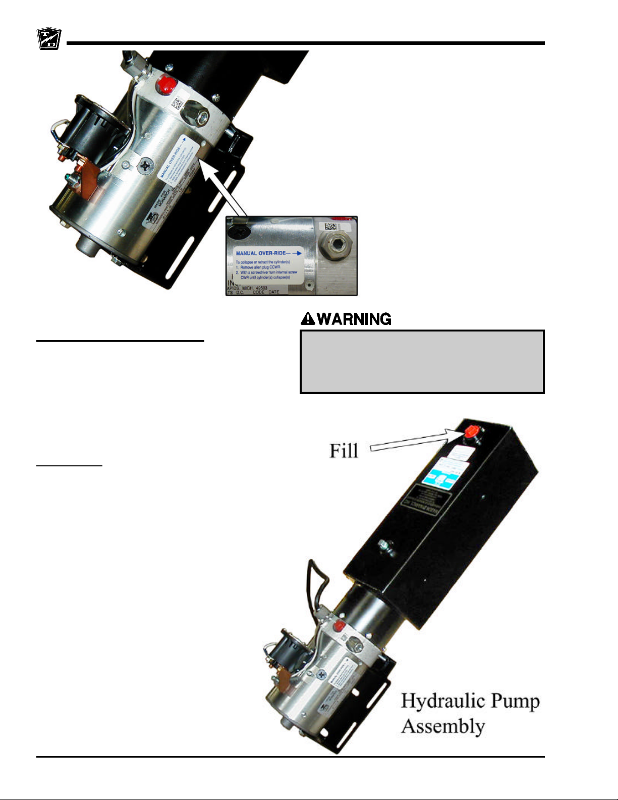
Manual Release
Lowering the Dump Manually
There is a manually operated valve located on the left
side of the hydraulic pump assembly (see illustration).
This valve should only be used if the dump fails to lower
by pressing the lowering button. The valve is covered
by an Allen screw. Remove the Allen screw to access
the valve then turn the internal screw clockwise to lower
the dump.
Lubrication
Under normal conditions, all of the pivot points
should be lubricated with chassis grease every 3months. This includes the upper and lower
hydraulic cylinder pivots and the dump bed pivot
points. Depending on the type of dump bed, there
may be more than one grease fitting for the bed
pivots. If grease fittings are not provided, then the
pins must be removed to apply grease.
The hydraulic fluid level of the tank should be
inspected weekly and filled as required (see
illustration).
Use only use Dextron automatic transmission fluid.
Using any other fluid may result in damage to the
hydraulic pump. The tank must be filled only when
the dump is in its fully lowered position. Fill the
tank to within appriximatly 1-1/2 to 2-1/2 inches
from the filler hole.
Do not place any body part underneath a raised
bed unless the bed prop rod is in place. Severe
bodily injury will result if the bed lowers
unexpectedly.
Safety Rules
Page 33
SAFETY RULES AND OPERATING INSTRUCTIONS
Page 19
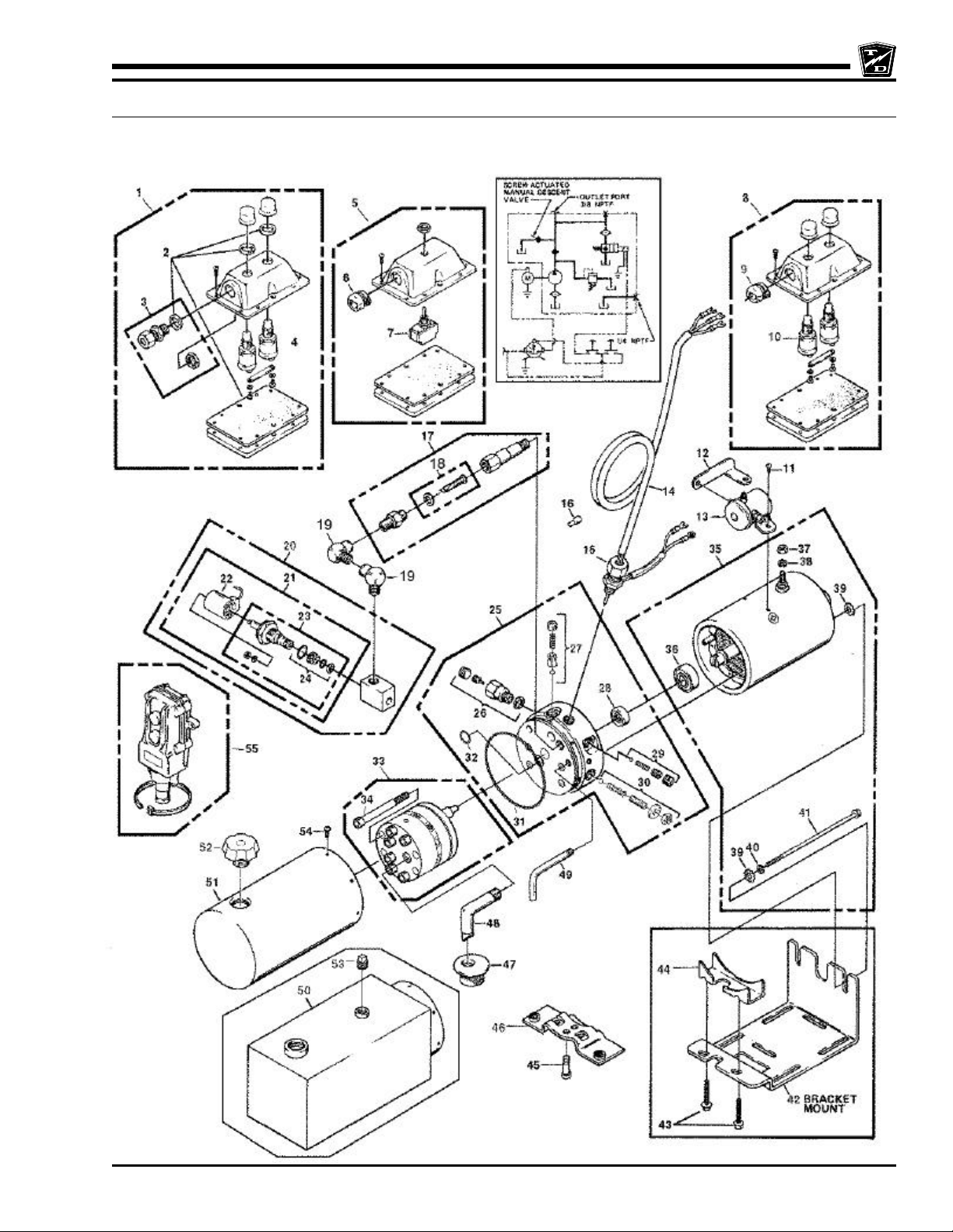
HYDRAULIC PUMP EXPLODED VIEW
This view is provided by the manufacturer of the pump and should only be used as a reference. Refer to the pump
manufacturere web site for current detailed information: http://www.monarchhyd.com/. The pump model # is M-303.
Safety Rules
Page 34
SAFETY RULES AND OPERATING INSTRUCTIONS
Page 20
CHARGING YOUR VEHICLE
Explosive mixtures of Hydrogen gas are
present within battery cells at all times. Do
not work with or charge battery in an area
where open flames (including gas furnace
or water heater pilots), sparks, cigarettes,
or any other sources of combustion are
present. Always provide ample ventilation
in rooms where batteries are being
charged. Failure to do so may result in
severe bodily injury and/or property
damage.
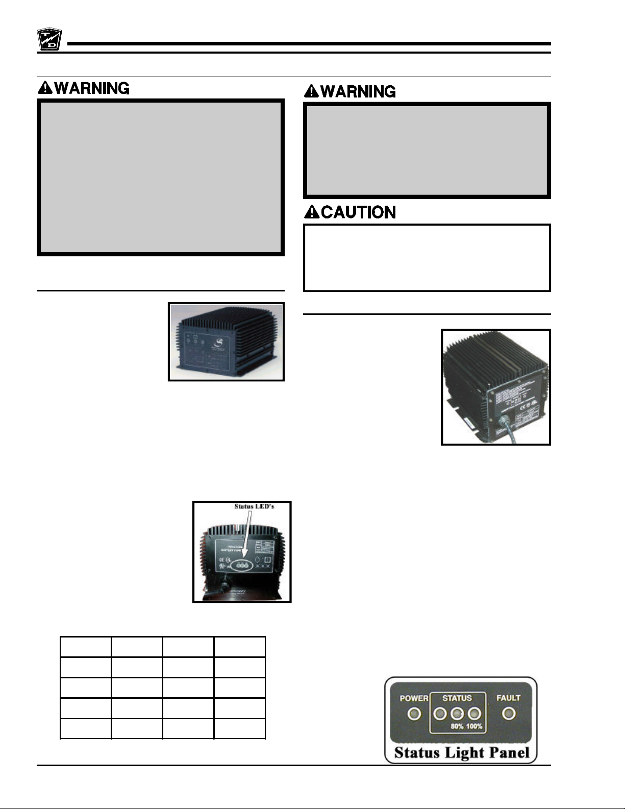
Signet Charger Operation, Model HB Series
The Signet® HB series
chargers use a semiautomatic charging system.
The charger will turn itself
ON when the AC power cord
is connected to the AC
power source and turn itself
OFF when the batteries are
fully charged. Refer to the data plate on the charger for
the voltage and type power required for the charger.
There is a series of LED’s on the faceplate of the charger
that serve two functions:
1. Status of charge. The LED’s will display an
approximate percent of charge during the charging
cycle. Refer to the table below.
2. Error condition. All three
LED’s flashing is an
indication of a charging
problem (charger will also
be beeping). Refer to the
Charger Troubleshooting
section for information on
error codes.
Typical Signet® Built In
Battery electrolyte is poisonous and
dangerous. It contains sulfuric acid. Avoid
contact with skin eyes or clothing. Wear
rubber gloves and safety glasses while
servicing batteries. DO NOT INGEST! This
may result in severe bodily injury.
The key switch must be in the “OFF” position
when charging the batteries. Failure to turn
the key switch “OFF” may result in damage to
the vehicles electrical system.
Signet Charger Operation, Model HBS series
The Signet® HBS series
chargers are fully automatic.
The charger will turn itself ON
when the AC power cord is
connected to the AC power
source and turn itself OFF
when the batteries are fully
charged. Once the charge
cycle is complete, the charger
will continue to monitor the
batteries. If the battery
voltage drops during storage, the charger will start a new
cycle to keep the batteries fully charged.
NOTE: If the charger restarts during a short time
period of storage, then it would be an
indication of faulty batteries.
Refer to the data plate on the charger for the voltage
and type power required for the charger.
There is a series of LED’s on the faceplate of the charger
that serve two functions:
1. Status of charge. The STATUS LED’s will display
an approximate percent of charge during the
charging cycle. Refer to the table below.
Typical Signet® HBS
Charging State
0 to 50% Blinking OFF OFF
50% to 75% ON Blinking OFF
75% to 100% ON ON Blinking
Cycle complete ON ON ON
LED1 LED2 LED3
Safety Rules
2. Error condition. The FAULT LED flashing is an
indication of a charging problem (charger may also
be beeping). Refer to the Charger
Troubleshooting section for information on error
codes.
Page 35
SAFETY RULES AND OPERATING INSTRUCTIONS
Page 21
Lestronic II® Charger Operation
The Lestronic II® charger is a semi-automatic charging
system. The charger will turn itself ON when the AC
power cord is connected to the AC power source and
turn itself OFF when the batteries are fully charged. Refer
to the data plate on the charger for the voltage and type
power required for the charger. When plugged in, the
charger assumes that the batteries require charging and
will charger for a minimum of approximately 4-hours.
This charger should not be plugged in until the batteries
are discharged beyond 50% or the batteries may be
overcharged..
New Battery Break in
New batteries require a break in period of up to 40-cycles.
The batteries will not have their full capacity during this
break in period and may require longer charging times.
To obtain the maximum battery life:
Charge the batteries only after they reach a normal
discharge as indicated on the Battery Status Indicator
(BSI). Failure to follow this guideline could result in the
batteries entering an overcharge state, which will reduce
the life of the batteries. If you find it necessary to charge
the batteries before they are completely discharged we
recommend waiting until they are discharged a minimum
of 25% to reduce the possibility of overcharging. Refer
to Vehicle Controls in this section for information on how
to read the BSI.
Do not discharge the batteries beyond a normal
discharge as indicated on the BSI. Refer to Vehicle
Controls in this section for information on how to read
the BSI.
Check the battery electrolyte once a week. Do not charge
the batteries if the battery electrolyte is low. Charging
when the electrolyte is low will damage the batteries and
shorten their life-span. Only authorized personnel should
perform battery maintenance including maintaining the
battery electrolyte level. Refer to Section Maintenance,
Service and Repair for battery maintenance
information.
Do not interrupt the charging cycle. When the charger is
plugged in, allow it to turn off before disconnecting.
Interrupting the charging cycle could lead to overcharging
or discharging the batteries too deep. Both circumstances
will shorten the life of the batteries.
Charging Time
Average charging time is 8 to 10-hours. The time required
to fully charge your batteries will vary depending on:
• Capacity of the batteries, higher capacity requires
longer charge time.
• Output of the charger, higher output requires less
charge time.
• Depth of discharge, the deeper a battery is
discharged, the longer it takes to charge.
• Temperature, low temperatures require longer charge
time.
It is not unusual for charge times to exceed 15-hours,
especially with new batteries.
Charging time is limited to 20-hours (HBS) or 18-hours
(HB). A fault will occur if the charging time exceeds the
20-hour limit.
STORING / RETURNING TO
SERVICE
Both storing your vehicle and returning it to service
should only be performed by authorized personnel.
Storing Your Vehicle
• Clean the batteries, then fill and charge before
putting the vehicle in storage. Do not store batteries
in a discharged condition.
• Lube all grease fittings.
• Clean, dry, and check all exposed electrical
connections.
• Inflate tires to proper pressure (if applicable).
• For extended storage, the vehicle should be elevated
so that the tires do not touch the ground.
If stored for a prolonged period, the batteries should be
charged as follows:
Returning to
Service
• Check the
battery’s state
of charge and
charge if
required.
• Perform ALL
maintenance checks in the periodic checklist.
Storage
Temperature
(F)
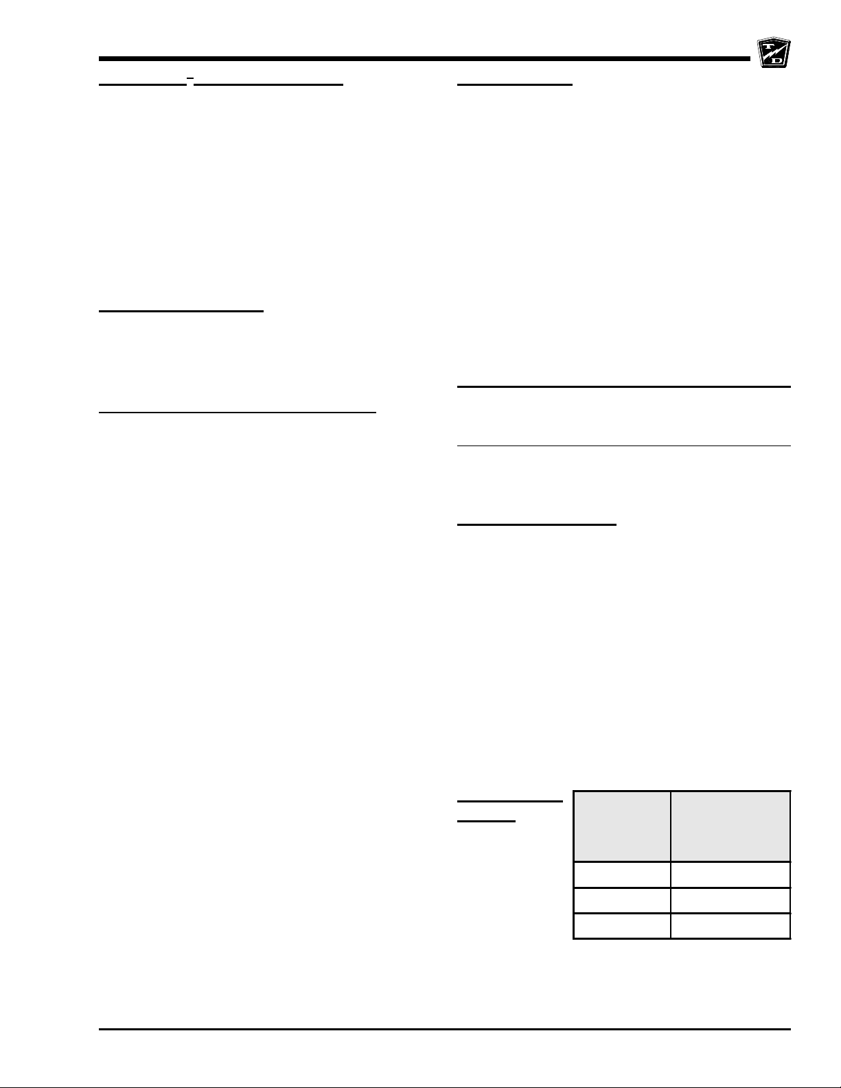
Over 60 1
Between 40 and 60 2
Below 40 6
Charging Interval
(months)
• Remove any blocks from the vehicle and/or place
the vehicle down on to the ground.
• Test drive before putting into normal service.
Safety Rules
Page 36
SAFETY RULES AND OPERATING INSTRUCTIONS
Page 22
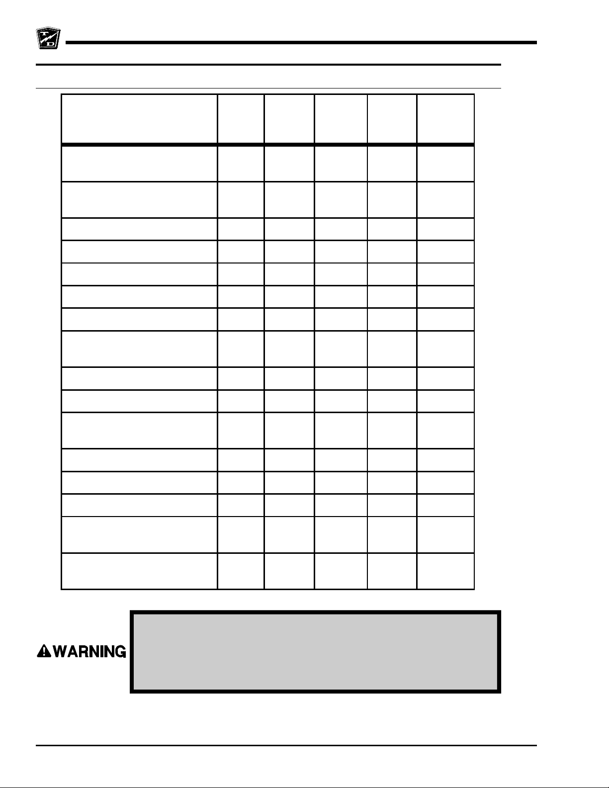
PERIODIC MAINTENANCE CHECKLIST
Maintenance Item
2, 3
Check Condition of Tires and
Tire Pressure
Check All Lights, Horns,
Beepers and Warning Devises
Weekly
(20hrs)
l
l
1
Monthly
(80hrs)
1
Quaterly
(250hrs)
Check and Fill Batteries l
Check Brake System l
Check Steering System l
Check for Fluid Leaks l
Lubricate Vehicle l
Clean and Tighten All Wire
Connections
Wash and Service Batteries l
l
1
Annual
(500hrs)
Semi -
1
(1000hrs)
Annualy
1
Check Park Brake l
Check Motor Brushes and
Blow Out Motor
Check Front Wheel Bearings l
Check Rear Axle Oil l
Change Rear Axle Oil l
Check and Tighten all Nuts and
Bolts
Clean and Repack Front Wheel
Bearings
1, 2, 3 - See notes on following pages.
Only properly trained and authorized technicians should perform
maintenance or repairs to this vehicle. Repairs or maintenance by
improperly trained or unauthorized personnel could cause improper
operation of the vehicle or premature failure of components resulting
in severe bodily injury and/or property damage.
l
l
l
Safety Rules
Page 37
SAFETY RULES AND OPERATING INSTRUCTIONS
Page 23
STANDARD PERIODIC MAINTENANCE SCHEDULE
FOR THE SMART VIEW DISPLAY
NOTE: The maintenance function is optional. Your vehicle may be equipped with a customized maintenance
schedule
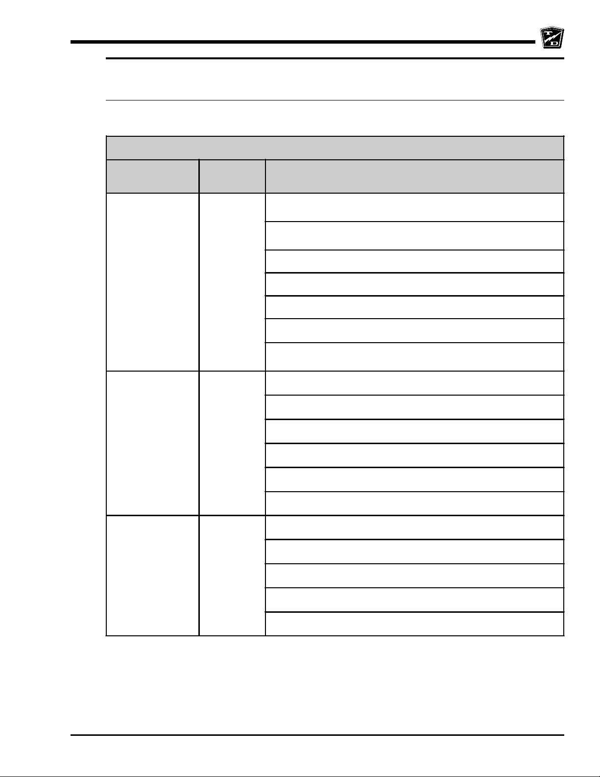
PREVENTATIVE MAINTENANCE SCHEDULE
MAINTENANCE
LEVEL
1 500
2 1000
HOUR
INTERVAL
1
Inspect the brake system including the park brake and mounting
harware
Inspect the steering system, tighten the steering shaft coupler on
the steering gear input shaft
Lubricate the vehicle, check for leaks
Inspect safety interlocks
Inspect front and rear wheel bearings
Inspect and adjust fork collar bearings (3-wheel trucks only)
Inspect and tighten all nuts and bolts. First 500 hours and then
every 1000 hours.
Inspect and tighten all nuts and bolts
Clean and repack front wheel bearings
Inspect and tighten all wire connections
Inspect the motor brushes and commutator
MAINTENANCE TO BE PERFORMED
2,3
3 2000
1, 2, 3 - See notes on following pages.
Inspect the king pin bushings
Check front end alignment
Change oil in the drive and rear axle
Flush hydraulic brake system
Inspect suspension bushings
Replace brake pedal/treadle return spring
Inspect frame for damage
Safety Rules
Page 38
SAFETY RULES AND OPERATING INSTRUCTIONS
Page 24
Daily Visual inspection:
Tire condition and pressure.
External frame damage (body).
Operation of all lights and warning alarms and/or horns.
Smooth and proper operation of all controls such as but not limited to:
• Accelerator pedal, Brake pedal, Steering, Parking brake, etc.
• Proper operation of all locking devises such as but not limited to:
• Tool box, Removable battery trays, Cargo box, Cab doors, etc.
• Proper operation of all interlocking switches such as but not limited to:
• Key switch, Seat interlock switch, Charger interlock switch, etc.
Inspect for leaking fluids or grease.
MAINTENANCE GUIDELINES FOR
SEVERE DUTY APPLICATIONS
1. This maintenance checklist is based on the average application. If the vehicle is operated under
“severe conditions”, service procedures should be conducted more frequently than specified. The
frequency of service under severe conditions is determined by the use of the vehicle. The owner/
operator must evaluate the operating environment to determine the increase in maintenance frequency.
In addition, the whole vehicle should be inspected monthly for signs of damage. The damage must be
repaired immediately.
The following list is meant as a guide and is not all-inclusive of a “severe duty” application.
• Extreme temperature.
• Bumpy, dusty, or ill maintained roads.
• Excessively wet areas.
• Corrosive or contaminated areas.
• Frequent loading of vehicle at/near capacity.
• Use on multiple shifts.
2. Any deficiencies found during an inspection should corrected before the vehicle is returned to service.
3. Battery water level should be inspected on a weekly schedule.
Safety Rules
-
R
D
O
L
Y
A
T
T
h
e
B
e
s
t
W
a
y
T
o
U
N
N
R
s
s
e
n
i
s
u
B
r
u
o
Y
G
t
u
o
o
b
A
Page 39
General Maintenance
TABLE OF CONTENTS
Maintenance Guidelines ...............................2
Troubleshooting Guide .................................3
Lubrication Chart ..........................................4
Page 40
Maintenance, Service and Repair
MAINTENANCE GUIDELINES
Periodic maintenance and service must be performed on this vehicle. Failure to
complete these scheduled maintenance and service procedures can result in
severe bodily injury and/or property damage. It is the owner and/or operators
responsibility to insure that proper service and maintenance is performed on
the vehicle, described in this manual.
1. Make sure the key-switch is in the “OFF” position, then remove the key.
2. Place the forward-reverse switch in the center “OFF” position.
3. Set the park brake.
Before starting any repairs:
4. Place blocks under the front wheels to prevent vehicle movement.
5. Disconnect the main positive and negative cables at the batteries.
Read and follow all of the guidelines listed below. Failure to follow these
guidelines may result in severe bodily injury and/or property damage.
• Avoid fire hazards and have fire protection equipment present in the work area. Conduct vehicle
performance checks in an authorized area where safe clearance exists.
• Before starting the vehicle, follow the recommended safety procedures in Section 2, “Safety
Rules and Operational Information.”
• Ventilate the work area properly.
• Regularly inspect and maintain in a safe working condition, brakes, steering mechanisms, speed
and directional control mechanisms, warning devices, lights, governors, guards, and safety
devices.
• Inspect and maintain battery limit switches, protective devices, electrical conductors, and
connections in conformance with Taylor-Dunn’s® recommended procedures.
• Keep the vehicle in clean condition to minimize fire hazards and facilitate detection of loose or
defective parts.
• Do not use an open flame to check level or leakage of battery electrolyte.
• Do not use open pans of fuel or flammable fluids for cleaning parts.
• Only properly trained and authorized technicians should perform maintenance or repairs to this
vehicle.
Maintenance Page 2
Page 41
Maintenance, Service and Repair
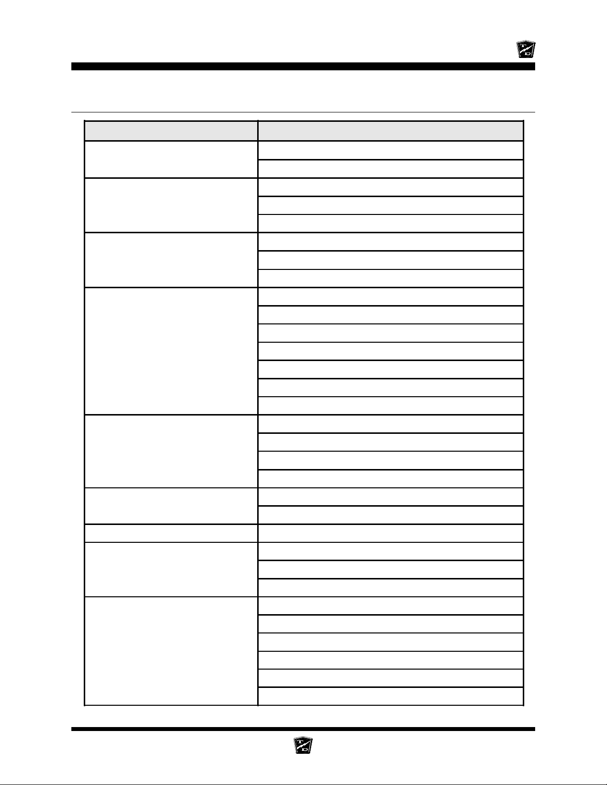
TROUBLESHOOTING GUIDE
Symptom Probable Cause
Steering Pulls in One Direction
Hard Steering
Excessive Steering Play
Lack of Power or Slow Operation
Front End Out of Alignment
Low Tire Pressure
Dry Lube Points in Steering Linkage
Damaged King Pin/Ball Joint
Low Tire Pressure
Worn Ball Joints
Mis-Adjusted or Worn Steering Gear
Loose Steering Linkage
Brakes or Parking Brakes Dragging
Worn Drive Gears
Front End Out of Alignment
Speed Control System Fault
Speed Control System Overheated
High/Low Speed Switch in Low or wiring to the Switch is Faulty
Low Speed Cutback Due to Maintenance Meter Trip (optional)
Worn Drive Gears or Bearings
Abnormal Noise
Oil Leak in Rear Bearing Area
Brake Pedal Soft or Spongy Air in Brake Lines
Brake Pedal Low
Braking Power Low
Worn Front /Rear Axle Bearings
Loose Lug Nuts
Motor Bearings Worn
Rear Wheel Bearing and/or Gasket Failed
Drive Over Filled
Brake Worn (1/16" Wear Limit)
Brake Fluid Low
Brakes Out of Adjustment
Brake Worn (1/16" Wear Limit)
Brake Pads Contaminated with Fluid
Brake Pedal Linkage Binding
Brakes Out of Adjustment
Air in Brake Lines
Trailer Brake System Faulty (optional)
Maintenance Page 3
Page 42
Maintenance, Service and Repair
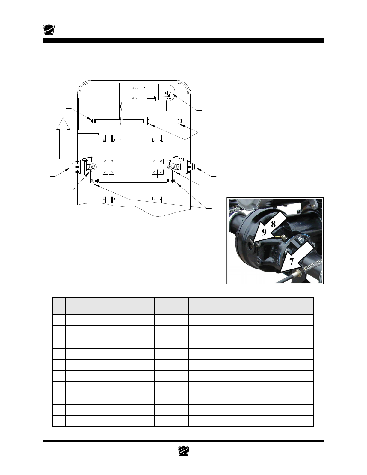
LUBRICATION CHART
3
2
FRONT
4
1
2
3
4
Rear Axle Lubrication
1
Front End Lubrication
# Description Locations Lubricant Type
1 Ball Joints 4 General Purpose Grease
2 Pedal Linkages 3 General Purpose Grease
3 Front Wheel Bearings 2 High Temperature Wheel Bearing Grease
4 King Pin 2 General Purpose Grease
7 Drive Drain Plug 1
8 Drive Level Plug 1
9 Drive Fill Plug 1 SAE 80W90 Gear Oil
Maintenance Page 4
Page 43
Front Axle Service
TABLE OF CONTENTS
Inspect the Front Wheel Bearings
and King Pin...........................................2
Adjust Front Wheel Bearings.......................3
Front Axle Removal and Installation ............4
Removal ...................................................................4
Installation ................................................................ 5
Front Axle Disassembly ................................6
Replace Front Wheel Bearings .....................7
Replace the King Pins and Bushings...........9
Replace the Steering Knuckle ......................11
Page 44
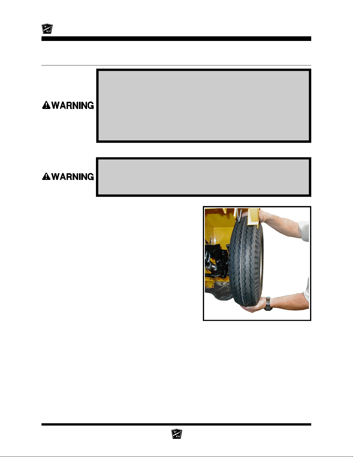
Maintenance, Service, and Repair
INSPECT THE FRONT WHEEL BEARINGS AND KING PIN
1. Make sure the key-switch is in the “OFF” position, then remove
the key.
2. Place the forward-reverse switch in the center “OFF” position.
3. Set the park brake.
4. Place blocks under the rear wheels to prevent vehicle movement.
5. Disconnect the main positive and negative cables at the batteries.
6. Raise the front of the vehicle and support with jack stands.
Always use a lifting strap, hoist, and jack stands, of adequate capacity
to lift and support the vehicle. Failure to use lifting and support devices
of rated load capacity may result in severe bodily injury.
7. Grab the top and bottom of the tire/wheel assembly.
Feel for any movement or play while pulling and
pushing on the top and bottom of the tire. Any
movement or play is an indication of loose wheel
bearings or king pin.
NOTE: Refer to the Adjust Front Wheel
Bearings section for information
regarding the adjustment of the wheel
bearings.
NOTE: If the king pin is loose, then refer to
Replace the King Pins and
Bushings for information regarding
replacing the king pin bushings. There
are no adjustments for the king pin or
bushings.
8. Spin the wheel and listen for any grinding noise.
Any grinding noise may be an indication of worn or
damaged wheel bearings.
NOTE: Refer to the Replace Front Wheel Bearings section for
information regarding the replacement of the wheel bearings.
9. Lower the vehicle.
10.Reconnect the main positive and negative cables at the batteries.
11. Remove the blocks from behind the wheels.
12.Release the park brake and test drive the vehicle.
Front Axle Page 2
Page 45
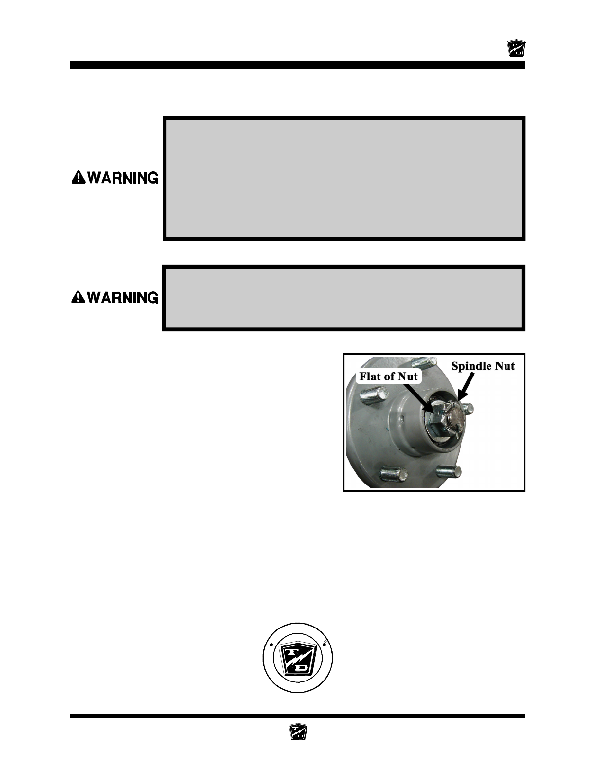
Maintenance, Service, and Repair
ADJUST FRONT WHEEL BEARINGS
1. Make sure the key-switch is in the “OFF” position, then remove
the key.
2. Place the forward-reverse switch in the center “OFF” position.
3. Set the park brake.
4. Place blocks under the rear wheels to prevent vehicle movement.
5. Disconnect the main positive and negative cables at the batteries.
6. Raise the front of the vehicle and support with jack stands.
Always use a lifting strap, hoist, and jack stands, of adequate capacity
to lift and support the vehicle. Failure to use lifting and support devices
of rated load capacity may result in severe bodily injury.
7. Remove the hub dust cap and cotter pin.
8. While rotating the hub, tighten the spindle nut to
30 ft-lbs. This seats the bearings.
9. Back off the spindle nut one flat until the hub turns,
but is not loose.
10. Spin the wheel and listen for any grinding noise.
Any grinding noise may be an indication of worn or
damaged wheel bearings.
NOTE: Refer to the Replace Front Wheel
Bearings section for information
regarding the replacement of the wheel
bearings.
11. Install a new cotter pin.
12. Install the dust cap.
13. Lower the vehicle.
14. Reconnect the main positive and negative cables at the batteries.
15. Remove the blocks from behind the wheels.
16. Release the park brake and test drive the vehicle.
Hub with Dust Cap Removed
-
R
D
O
L
U
Y
A
T
T
h
e
B
e
s
t
W
a
y
T
o
N
N
R
s
s
u
B
r
u
o
Y
t
G
u
o
o
b
A
Front Axle Page 3
s
e
n
i
Page 46
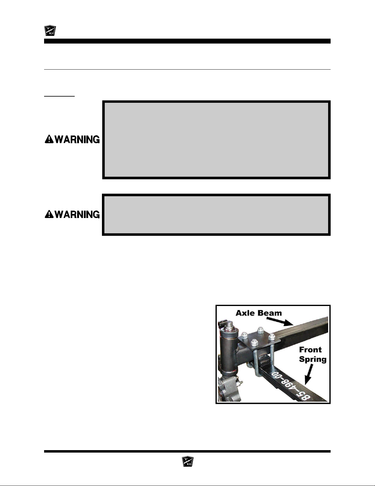
Maintenance, Service, and Repair
FRONT AXLE REMOVAL AND INSTALLATION
Removal
1. Make sure the key-switch is in the “OFF” position, then remove
the key.
2. Place the forward-reverse switch in the center “OFF” position.
3. Set the park brake.
4. Place blocks under the rear wheels to prevent vehicle movement.
5. Disconnect the main positive and negative cables at the batteries.
6. Raise the front of the vehicle and support with jack stands.
Always use a lifting strap, hoist, and jack stands, of adequate capacity
to lift and support the vehicle. Failure to use lifting and support devices
of rated load capacity may result in severe bodily injury.
7. Remove both front wheels. Refer to Tires and Wheels section for information regarding
removing the front wheels.
8. Tie up or support the front axle so it can not fall out of the vehicle.
9. Disconnect the drag link ball joint or rod end from the steering knuckle or the steering gear
pitman arm.
NOTE: Refer to the Replacing the Ball Joints section for information
regarding the removal of the ball joints or rod ends.
10. If equipped with front brakes, disconnect the
hydraulic brake lines from the brake bodies.
11. Disconnect the front axle beam from the front
springs and remove the axle from the vehicle.
NOTE: In some configurations the front
springs and or shocks will have to be
removed in order to remove the axle
beam. Refer to section Front
Suspension for information
regarding removing the springs and
shocks.
Front Axle Page 4
Page 47
Installation
6. Raise the front of the vehicle and support with jack stands.
Maintenance, Service, and Repair
1. Make sure the key-switch is in the “OFF” position, then remove
the key.
2. Place the forward-reverse switch in the center “OFF” position.
3. Set the park brake.
4. Place blocks under the rear wheels to prevent vehicle movement.
5. Disconnect the main positive and negative cables at the batteries.
Always use a lifting strap, hoist, and jack stands, of adequate capacity
to lift and support the vehicle. Failure to use lifting and support devices
of rated load capacity may result in severe bodily injury.
7. Install the front axle in reverse order of removal.
NOTE: Use all new cotter pins.
NOTE: Refer to the Replacing the Ball Joints section for information
regarding the installing the ball joints or rod ends.
NOTE: Refer to Tires and Wheels section for information regarding
removing the front wheels.
8. Realign the front wheels. Refer to Steering Component Service section for information
regarding realigning the front wheels.
9. If equipped with front brakes, bleed the brakes. Refer to Brake Service section for information
regarding bleeding the brakes.
10. Lower the vehicle.
11. Reconnect the main positive and negative cables at the batteries.
12. Remove the blocks from behind the wheels.
13. Release the park brake and test drive the vehicle.
-
R
D
O
L
Y
A
T
T
h
e
B
e
s
t
W
a
y
T
o
U
N
N
R
s
s
e
n
i
s
u
B
r
u
o
Y
G
t
u
o
o
b
A
Front Axle Page 5
Page 48
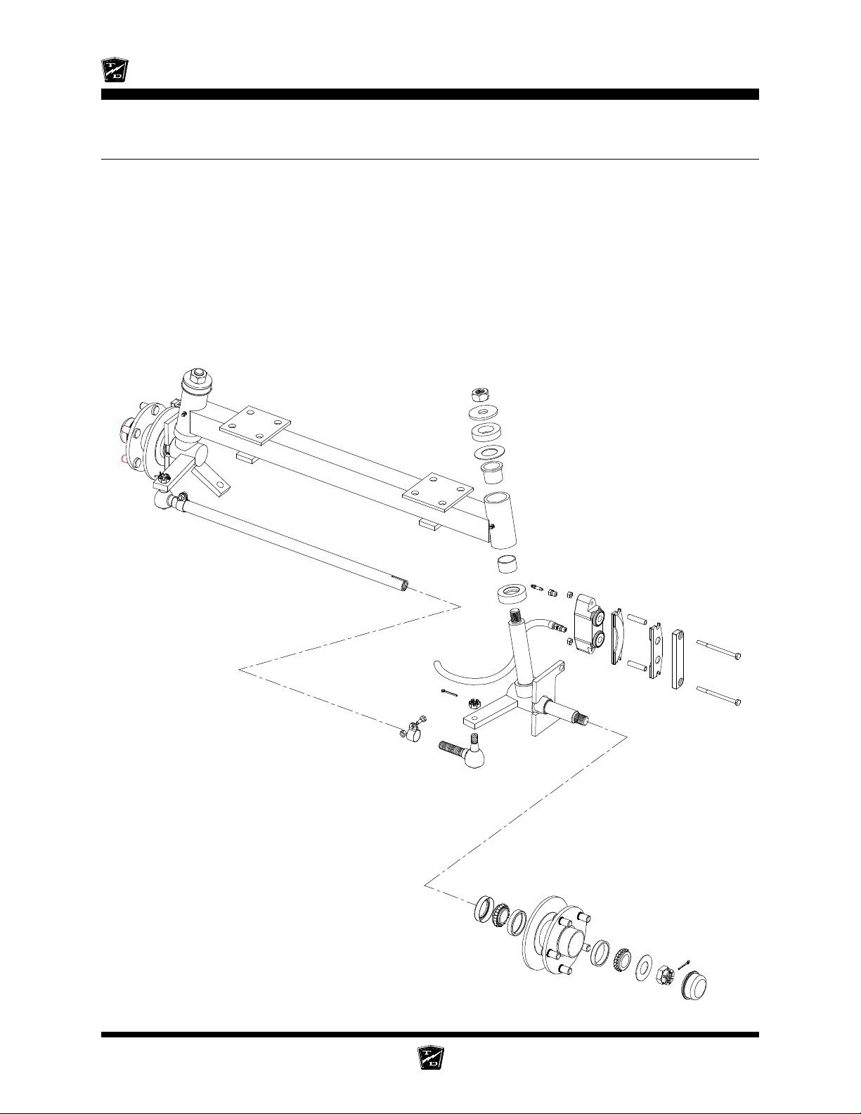
Maintenance, Service, and Repair
FRONT AXLE DISASSEMBLY
Disassembling and reassembling involves removing and replacing the left and right steering knuckles
and king pin bushings. Refer to the following sections for information regarding these procedures:
Replace the Steering Knuckle
Replace the King Pins and Bushings
NOTE: The front axle does not have to be removed unless the axle beam
must be replaced. Refer to Front Axle Removal and
Installation for information regarding removing the front axle.
Axle with integral king pin shown
Front Axle Page 6
Page 49
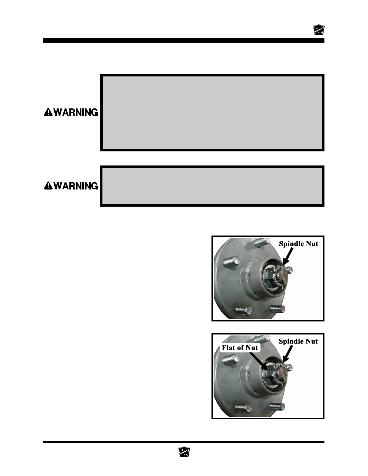
Maintenance, Service, and Repair
REPLACE FRONT WHEEL BEARINGS
1. Make sure the key-switch is in the “OFF” position, then remove
the key.
2. Place the forward-reverse switch in the center “OFF” position.
3. Set the park brake.
4. Place blocks under the rear wheels to prevent vehicle movement.
5. Disconnect the main positive and negative cables at the batteries.
6. Raise the front of the vehicle and support with jack stands.
Always use a lifting strap, hoist, and jack stands, of adequate capacity
to lift and support the vehicle. Failure to use lifting and support devices
of rated load capacity may result in severe bodily injury.
7. Remove the tire/wheel assembly from the hub. Refer to Replace the Steering Knuckle for
information regarding removing the steering knuckle.
8. Remove the hub dust cap, cotter pin, and spindle nut.
9. Remove the hub from the steering knuckle.
NOTE: For a front disc brake option you must
remove the brake body before
removing the hub. Refer to the
Brakes section for information
regarding the removal of the brake
body.
NOTE: Catch the outer bearing as it falls out.
10. Thoroughly clean all grease from the inside of the
hub and the bearings.
11. Inspect and replace the races and bearings as a
set.
NOTE: It is recommended to replace all four
bearings and races in the left and right
wheels as a set.
12. Assemble in reverse order, using new grease seals.
a. Pack inner and outer bearings with grease.
Hub with Dust Cap Removed
b. While rotating the hub, tighten the spindle nut to
30 ft-lbs. This seats the bearings.
c. Back off the spindle nut one flat until the hub
turns, but is not loose.
d. Install a new cotter pin.
Front Axle Page 7
Hub with Dust Cap Removed
Page 50
Maintenance, Service, and Repair
13. Install the hub dust cap.
14. Reinstall the brake body and the tire/wheel assembly.
NOTE: Refer to the Brakes section for information regarding the
installation of the brake body.
15. Lower the vehicle.
16. Reconnect the main positive and negative cables at the batteries.
17. Remove the blocks from behind the wheels.
18. Release the park brake and test drive the vehicle.
-
R
D
O
L
Y
A
T
T
h
e
B
e
s
t
W
a
y
T
o
U
N
N
R
s
s
e
n
i
s
u
B
r
u
o
Y
G
t
u
o
o
b
A
Front Axle Page 8
Page 51
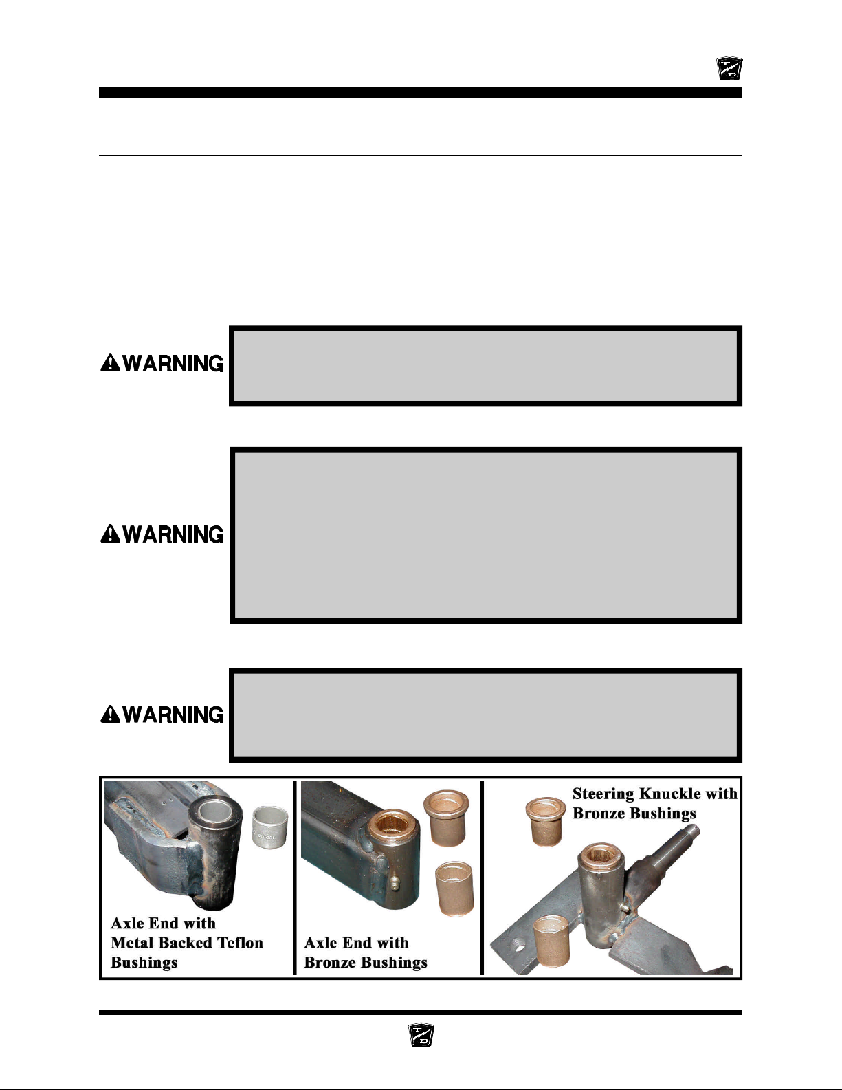
Maintenance, Service, and Repair
REPLACE THE KING PINS AND BUSHINGS
There are different types of king pin bushings depending on the configuration of your vehicle.
• Bronze bushings in the axle beam.
• Bronze bushings in the steering knuckle.
• Metal backed teflon bushings in the axle beam or suspension arm.
NOTE: Bronze bushings must be reamed or broached to the proper
diameter after they are pressed into the axle beam or steering
knuckle.
Failure to correctly broach or ream bronze bushings may result in
steering difficulty and loss of control of the vehicle causing severe
bodily injury and /or property damage.
Refer to the illustration below for the type of bushing in your vehicle.
1. Make sure the key-switch is in the “OFF” position, then remove
the key.
2. Place the forward-reverse switch in the center “OFF” position.
3. Set the park brake.
4. Place blocks under the rear wheels to prevent vehicle movement.
5. Disconnect the main positive and negative cables at the batteries.
6. Raise the front of the vehicle and support with jack stands.
Always use a lifting strap, hoist, and jack stands, of adequate capacity
to lift and support the vehicle. Failure to use lifting and support devices
of rated load capacity may result in severe bodily injury.
Front Axle Page 9
Page 52
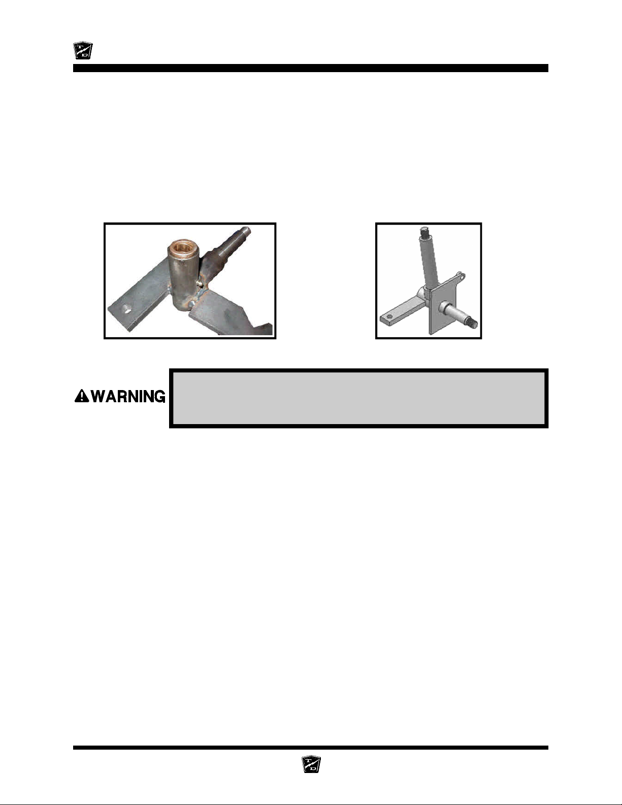
Maintenance, Service, and Repair
7. Remove the steering knuckle. Refer to Replace the Steering Knuckle for information
regarding removing the steering knuckle.
NOTE: It is not necessary to remove the tie rod or drag link for this
procedure.
8. Press the king pin bushings out from the axle, steering knuckle or suspension arm.
9. Press new bushings into the axle, steering knuckle or suspension arm.
a) Yoke with integral king pin: Ream or broach bronze bushings to 1.25” +/- 0.001”.
b) Yoke without king pin: Ream or broach bronze bushings to 0.880” +/- 0.001”.
Tpical Yoke without king pin Typical yoke with integral
king pin
Failure to correctly broach or ream bronze bushings may result in
steering difficulty and loss of control of the vehicle causing severe
bodily injury and/or property damage.
10.Inspect the king pin for damage or wear. If any damage or wear is noted then the king pin must
be replaced.
11. Reassemble in reverse order.
NOTE: Refer to Replace the Steering Knuckle for information on installing
the steering knuckle.
NOTE: It is recommended that the thrust washers or bearing be replaced
whenever replacing the king pin bushings. Refer to the
Replacement Parts section for the orientation of the bearing or
washers in your vehicle.
12.Grease the bushings (bronze only).
13.Lower the vehicle.
14.Reconnect the main positive and negative cables at the batteries.
15.Remove the blocks from behind the wheels.
16.Release the park brake and test drive the vehicle.
Front Axle Page 10
Page 53
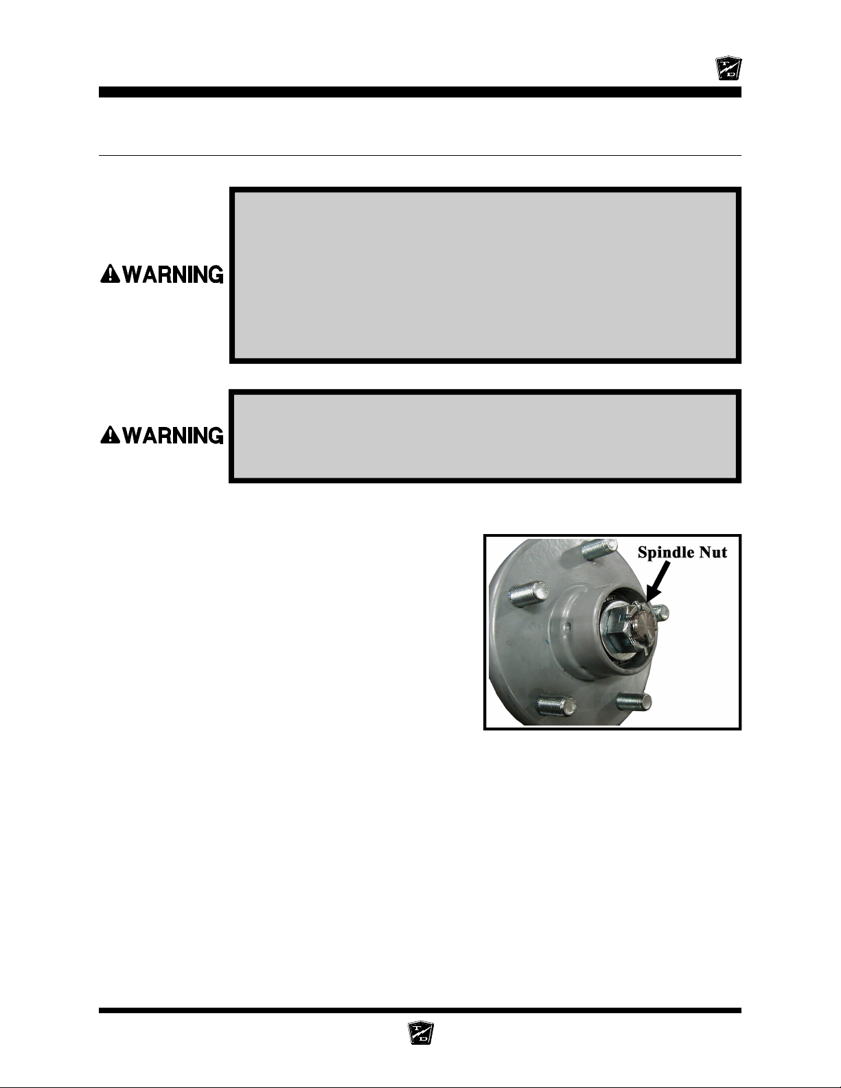
Maintenance, Service, and Repair
REPLACE THE STEERING KNUCKLE
1. Make sure the key-switch is in the “OFF” position, then remove
the key.
2. Place the forward-reverse switch in the center “OFF” position.
3. Set the park brake.
4. Place blocks under the rear wheels to prevent vehicle movement.
5. Disconnect the main positive and negative cables at the batteries.
6. Raise the front of the vehicle and support with jack stands.
Always use a lifting strap, hoist, and jack stands, of adequate capacity
to lift and support the vehicle. Failure to use lifting and support devices
of rated load capacity may result in severe bodily injury.
7. Remove the tire/wheel assembly. Refer to Tires and Wheels section for information regarding
removing the tire/wheel assembly.
8. Remove the hub bearing cap, cotter pin and nut,
then remove the hub from the steering knuckle.
NOTE: For a front disc brake option you must
remove the brake body before
removing the hub. Refer to the
Brakes section for information
regarding the removal of the brake
body. Do not remove the hydraulic
brake line from the brake body. If the
brake line is removed then it will be
necessary to bleed the brakes.
NOTE: Catch the outer bearing as it falls out.
9. Remove the drag link and/or tie rod from the
steering knuckle. Refer to Replace the Ball Joints, Tie Rods, Drag Link in this section for
information regarding removal of the drag link or tie rod.
10. While supporting the knuckle, remove the king pin and thrust bearing.
11. Remove the knuckle from the axle.
Hub with Dust Cap Removed
Front Axle Page 11
Page 54
Maintenance, Service, and Repair
12. Thoroughly clean and/or replace all bearings, nuts, washers, and bushings.
NOTE: Both the left and right side bushings and thrust bearings should be
replaced as a set.
13. Assemble in reverse order.
14. Pack the thrust bearing with grease.
15. Tighen the king pin nut as follows:
a) Yoke with integral king pin: Tighten the king pin nut until all of the up and down play is
removed and the yoke rotates freely. The rubber washer must compress slightly to create a seal
for the grease.
b) Yoke without king pin: tighten the king pin nut until all of the up and down play is removed
and the yoke rotates freely.
NOTE: Refer to Replace Front Wheel Bearings for information
regarding proper tightening of the spindle nut
16. Install new cotter pins.
17. Realign the wheels.
NOTE: Refer to the Steering section for information regarding realignment
of the front wheels.
18. Lower the vehicle.
19. Reconnect the main positive and negative cables at the batteries.
20. Remove the blocks from behind the wheels.
21. Release the park brake and test drive the vehicle.
-
R
D
O
L
Y
A
T
T
h
e
B
e
s
t
W
a
y
T
o
U
N
N
R
s
s
e
n
i
s
u
B
r
u
o
Y
G
t
u
o
o
b
A
Front Axle Page 12
Page 55
Steering Component Service
TABLE OF CONTENTS
Front End Alignment .....................................2
Inspect Ball Joints.........................................6
Inspect Rod Ends..........................................7
Adjust the Steering Gear...............................8
Replace the Steering Shaft ...........................10
Replace the Steering Wheel..........................12
Replace the Steering Gear ............................13
Replace the Ball Joints, Tie Rods, and Drag
Link..........................................................14
Replacing the Drag Link .......................................... 16
Replacing the Tie Rod ............................................. 17
Center the Steering Gear ..............................18
Pitman Shaft Alignment ................................18
Repair the Steering Gear...............................19
Exploded View of Steering Gear ............................22
Page 56
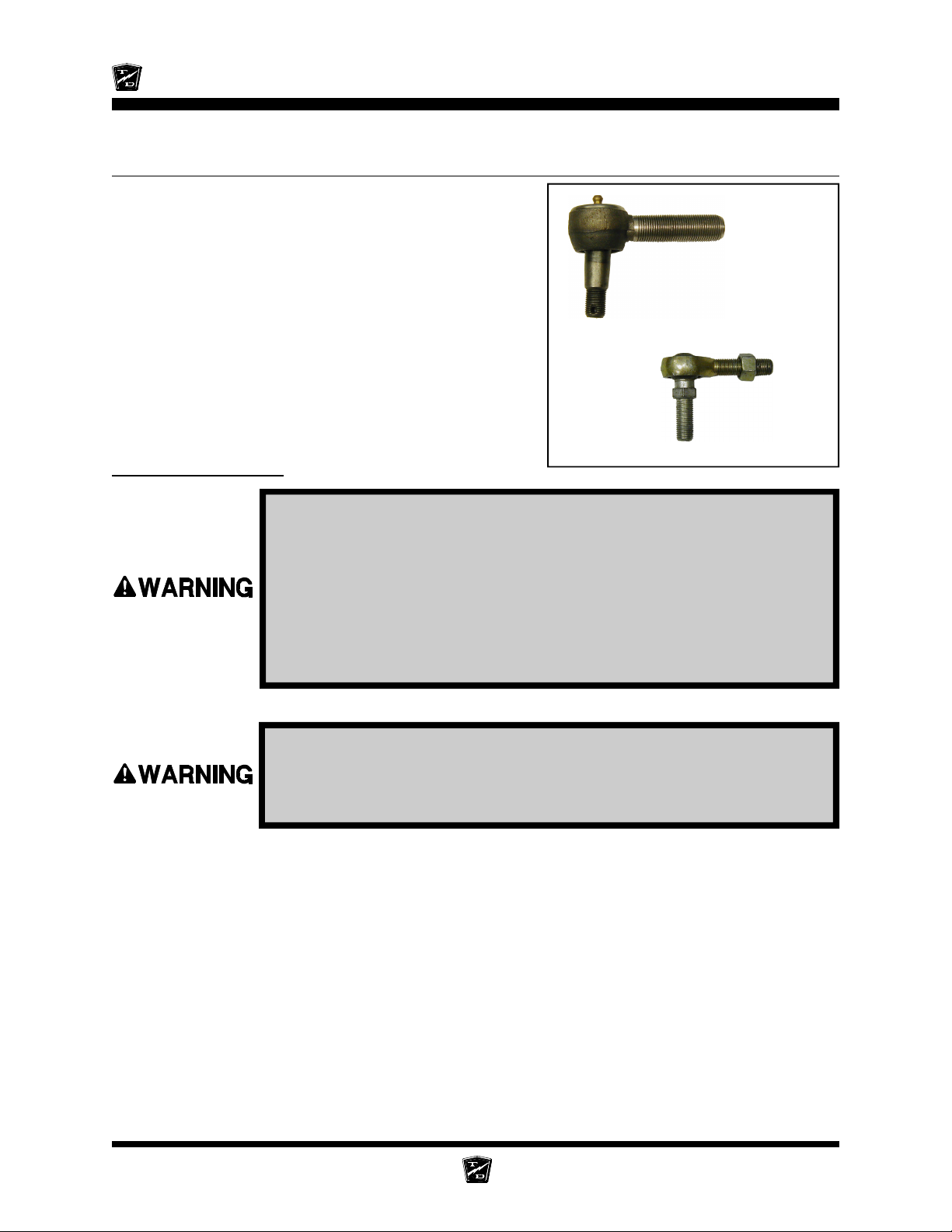
Maintenance, Service, and Repair
FRONT END ALIGNMENT
This section will refer to two different types of ball joints.
One type is has a grease fitting and a tapered shaft where
it is fitted to the steering arm or pitman arm. The second
type cannot be greased and has a straight shaft. See the
illustrations to the right. Depending on the configuration of
your truck, it may be equipped with one or both types of
ball joints.
In this text:
The first type has a grease fitting and will be referred to as
a “Ball Joint.”
The second type has no grease fitting and will be referred
to as a “Rod End.”
Center the Steering
1. Make sure the key-switch is in the “OFF” position, then remove
the key.
Ball Joint
Rod End
2. Place the forward-reverse switch in the center “OFF” position.
3. Set the park brake.
4. Place blocks under the rear wheels to prevent vehicle movement.
5. Disconnect the main positive and negative cables at the batteries.
6. Raise the front of the vehicle and support with jack stands.
Always use a lifting strap, hoist, and jack stands, of adequate capacity
to lift and support the vehicle. Failure to use lifting and support devices
of rated load capacity may result in severe bodily injury.
7. Turn the front wheels so that they are in the straight ahead position and then tie off the wheels
so that they cannot turn from the straight ahead position.
8. Disconnect the drag link from the pitman arm.
NOTE: Refer to Replace the Ball Joints section for information
regarding removing the ball joint or rod end from the drag link.
9. Center the steering gear and tie off the steering wheel so that it cannot rotate.
NOTE: Refer to Center the Steering Gear section for information
regarding centering of the steering gear.
Steering Page 2
Page 57
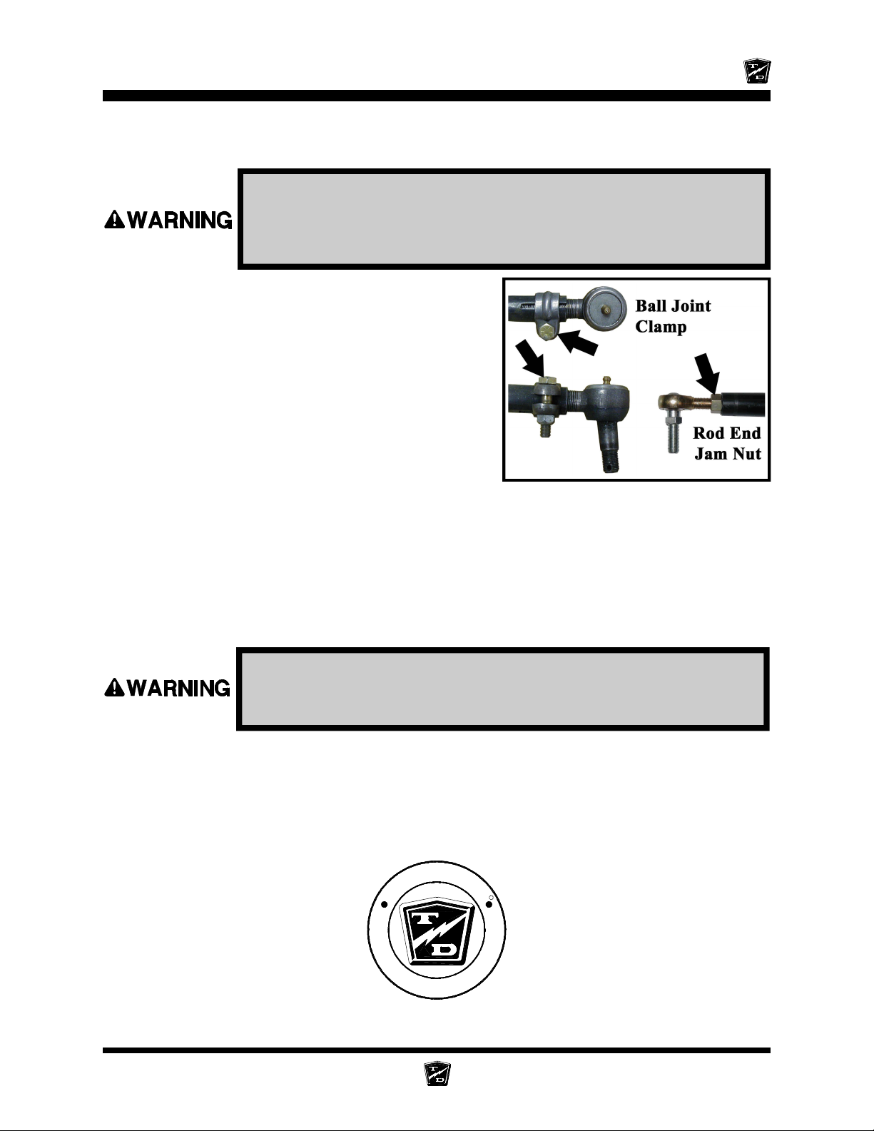
Maintenance, Service, and Repair
10. At this point both the steering wheel and the front wheels should be tied up and held in position.
If one or the other is not tied up then you must start from the beginning.
Do not drive the vehicle while the steering wheel or front wheels are
tied in position. Driving the vehicle while the steering wheel or front
wheels tied in the position may cause loss of control of the vehicle
resulting in severe bodily injury and/or property damage.
11. Loosen the ball joint clamps or the rod end jam nuts
on the drag link.
NOTE: Remember the position and orientation
of the clamps.
12. Adjust the drag link so that it can be easily inserted
into the pitman arm.
13. Tighten the ball joint or rod end nut as specified
below:
Ball joint - 40-45 ft-lbs.
Rod end - 20-25 ft-lbs.
14. If equipped with ball joints, position the ball joint
clamps in their original location and orientation.
15. Tighten the ball joint clamps (28-32 ft. lbs.) or the rod end jam nuts on the drag link.
16. Untie the steering wheel and the front wheels.
17. Reconnect the main positive and negative cables at the batteries.
18. Rotate the steering wheel from a full left turn to a full right turn and make sure that the ball joint
clamps do not contact any other component.
If the clamps are positioned so that they contact other components,
it may result in steering failure and loss of control of the vehicle
causing property damage and/or severe bodily injury.
19. Remove the blocks from behind the wheels.
20. Release the parking brake and test drive the vehicle.
-
R
D
O
L
Y
A
T
T
h
e
B
e
s
t
W
a
y
T
o
U
N
N
R
s
s
e
n
i
s
u
B
r
u
o
Y
G
t
u
o
o
b
A
Steering Page 3
Page 58
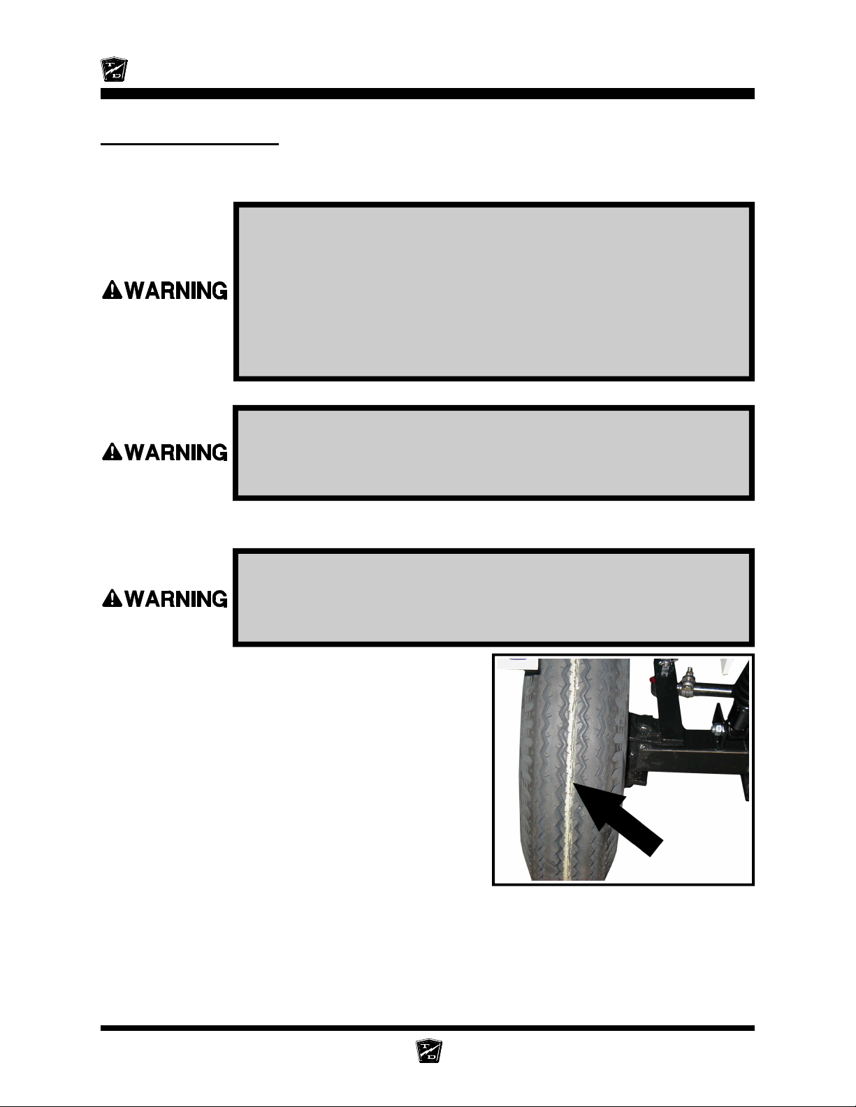
Maintenance, Service, and Repair
Front wheel alignment
NOTE: It is recommended to center the steering before aligning the front
wheels. Refer to the Center the Steering section for information.
1. Make sure the key-switch is in the “OFF” position, then remove
the key.
2. Place the forward-reverse switch in the center “OFF” position.
3. Set the park brake.
4. Place blocks under the rear wheels to prevent vehicle movement.
5. Disconnect the main positive and negative cables at the batteries.
6. Raise the front of the vehicle and support with jack stands.
Always use a lifting strap, hoist, and jack stands, of adequate capacity
to lift and support the vehicle. Failure to use lifting and support devices
of rated load capacity may result in severe bodily injury.
7. Turn the front wheels so that they are in the straight ahead position and tie off the steering wheel
so that it cannot rotate.
Do not drive the vehicle while the steering wheel or front wheels are
tied in position. Driving the vehicle while the steering wheel or front
wheels tied in the position may cause loss of control of the vehicle
resulting in severe bodily injury and/or property damage.
8. Using a piece of chalk, mark a line around the center
of both front tires.
HINT: Hold the chalk on the center of the tire
and rotate the tire to mark the line.
9. Loosen the ball joint clamps or the rod end jam
nuts on the tie rod.
NOTE: Remember the position and orientation
of the ball joint clamps.
10. Lower the front wheels to the ground and push the
vehicle back and forth a few feet to settle the
suspension.
Steering Page 4
Page 59
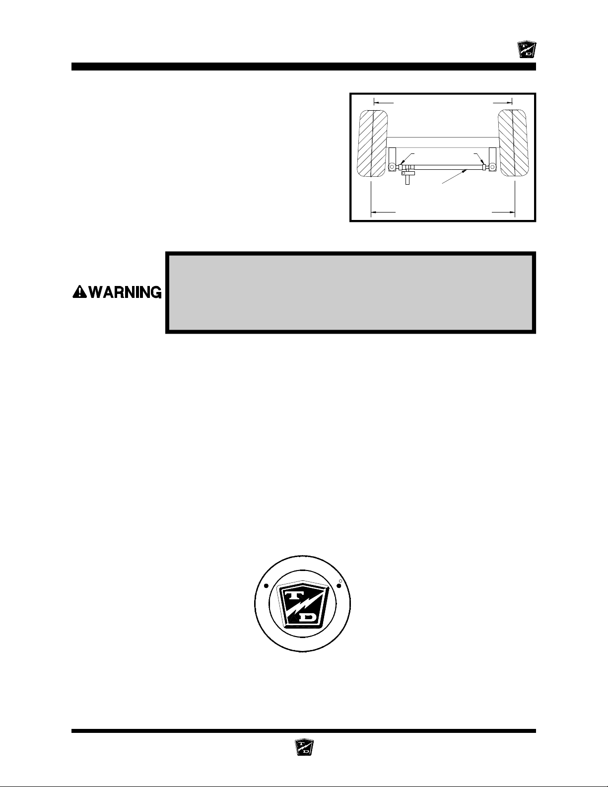
Maintenance, Service, and Repair
11. Measure the distance between the lines at the front
of the tires.
12. Measure the distance between the lines at the rear
of the tires.
13. Adjust the tie rod so that the distance at the front
and rear of the tires is the same.
14. If equipped with ball joints, position the ball joint
clamps in their original location and orientation.
15. Tighten the ball joint clamps (28-32 ft. lbs.) or the
rod end jam nuts.
16. Untie the steering wheel.
Rotate the steering wheel from a full left turn to a full right turn and
make sure that the ball joint clamps do not contact any other
component. Clamps positioned so that they contact other components
may result in steering failure and loss of control of the vehicle causing
severe bodily injury and/or property damage.
17. Reconnect the main positive and negative cables at the batteries.
18. Remove the blocks from behind the wheels.
19. Release the parking brake and test drive the vehicle.
Front Measurement
Sleeve Clamps
Tie Rod
Rear Measurement
-
R
D
O
L
Y
A
T
T
h
e
B
e
s
t
W
a
y
T
o
U
N
N
u
o
Y
G
t
u
o
o
b
A
Steering Page 5
R
s
s
e
n
i
s
u
B
r
Page 60
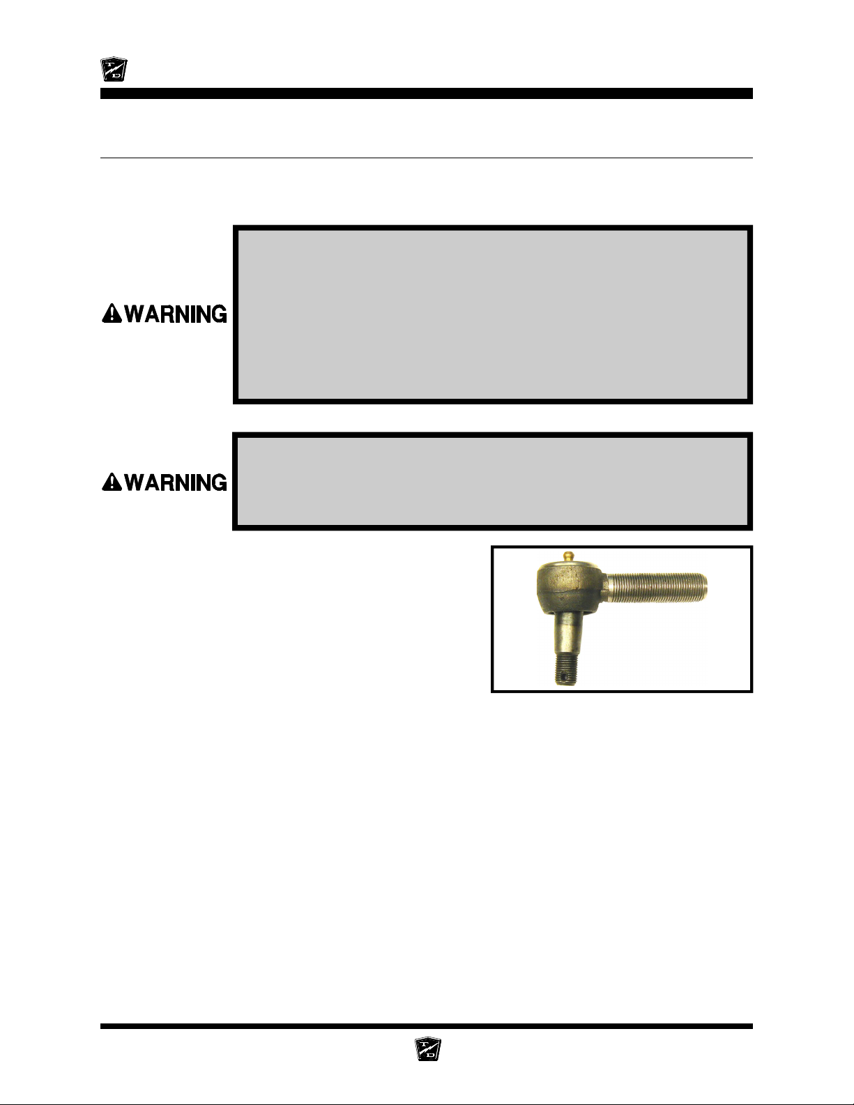
Maintenance, Service, and Repair
INSPECT BALL JOINTS
NOTE: A set of ball joints and/or rod ends will wear at the same rate. If a
ball joint and or rod end is worn out, then all should be replaced as
a set.
1. Make sure the key-switch is in the “OFF” position, then remove
the key.
2. Place the forward-reverse switch in the center “OFF” position.
3. Set the park brake.
4. Place blocks under the rear wheels to prevent vehicle movement.
5. Disconnect the main positive and negative cables at the batteries.
6. Tie off the front wheels so that they cannot turn.
Do not drive the vehicle while the steering wheel or front wheels are
tied in position. Driving the vehicle while the steering wheel or front
wheels tied in position may cause loss of control of the vehicle
resulting in severe bodily injury and/or property damage.
7. While watching the ball joints, rapidly rotate the
steering wheel to the left and right.
8. If the ball joint housing moves up or down then the
ball joint is worn out and should be replaced. Refer
to section Replacing a Ball Joint for information
regarding replacing ball joints.
9. Untie the front wheels.
10. Reconnect the main positive and negative cables
at the batteries.
11. Remove the blocks from behind the wheels.
12. Release the parking brake and test drive the vehicle.
Typical Ball Joint
Steering Page 6
Page 61
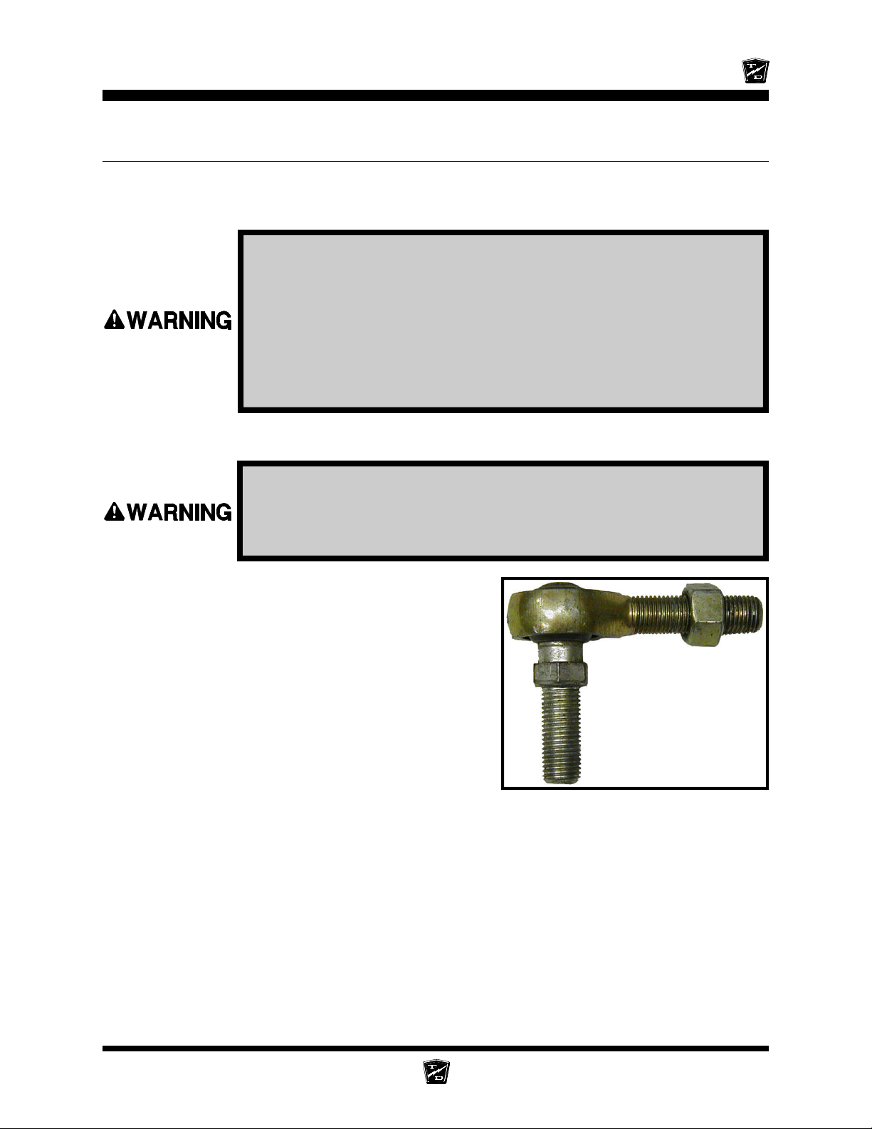
INSPECT ROD ENDS
NOTE: A set of ball joints and/or rod ends will wear at the same rate. If a
ball joint and or rod end is worn out, then all should be replaced as
a set.
1. Make sure the key-switch is in the “OFF” position, then remove the
key.
2. Place the forward-reverse switch in the center “OFF” position.
3. Set the park brake.
4. Place blocks under the rear wheels to prevent vehicle movement.
5. Disconnect the main positive and negative cables at the batteries.
6. Visually inspect each rod end for any signs of play between the ball and the nylon or brass
bushing in the housing.
Do not drive the vehicle while the steering wheel or front wheels are
tied in position. Driving the vehicle while the steering wheel or front
wheels tied in position may cause loss of control of the vehicle resulting
in severe bodily injury and/or property damage.
Maintenance, Service, and Repair
7. If any play is evident, then the rod end is worn out
and should be replaced. Refer to section Replace
the Ball Joints, Tie Rods, and Drag Link for
information regarding replacing ball joints.
8. Reconnect the main positive and negative cables
at the batteries.
9. Remove the blocks from behind the wheels.
10.Release the parking brake and test drive the vehicle.
< Stud
Typical rod end. Studded rod end shown, your
vehicle may be equipped with spherical rod
ends that do not have a stud.
Steering Page 7
Page 62
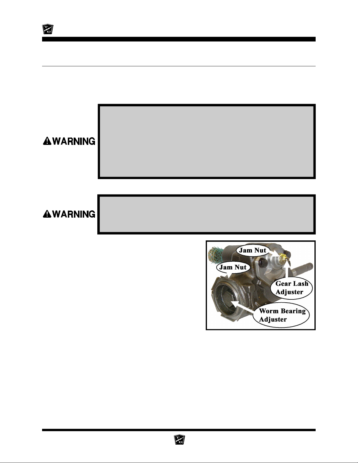
Maintenance, Service, and Repair
ADJUST THE STEERING GEAR
NOTE: In some vehicle configurations it may be necessary to remove the
steering gear to perform this procedure. Refer to Replace the
Steering Gear for information regarding removing the steering
gear.
1. Make sure the key-switch is in the “OFF” position, then remove the
key.
2. Place the forward-reverse switch in the center “OFF” position.
3. Set the park brake.
4. Place blocks under the rear wheels to prevent vehicle movement.
5. Disconnect the main positive and negative cables at the batteries.
6. Raise the front of the vehicle and support with jack stands.
Always use a lifting strap, hoist, and jack stands, of adequate capacity
to lift and support the vehicle. Failure to use lifting and support devices
of rated load capacity may result in serious bodily injury.
7. Disconnect the drag link from the pitman arm.
NOTE: Refer to Replace the Ball Joints
section for information regarding
removing the ball joint from the drag
link.
8. Loosen the gear lash jam nut and the worm bearing
adjuster jam nut.
9. Unscrew the gear lash adjuster all of the way to the
stop.
10. Loosen the worm bearing adjuster and then tighten
just enough to remove all end play from the input
shaft and then an additional 1/8 turn more.
11. While holding the worm bearing adjuster so that it cannot turn, tighten the worm bearing adjuster
jam nut.
12. Find the center position of the steering shaft:
A. Turn the steering shaft all of the way in one direction.
B. While counting the rotations, turn the steering shaft all of the way in the opposite direction.
C. Turn the steering shaft 1/2 the number of turns in the original direction.
Steering Page 8
Page 63
Maintenance, Service, and Repair
13. While rotating the input shaft back and forth through its centered position, adjust the gear lash
adjusting screw so that there is a slight drag as the steering gear is rotated through its centered
position.
14. While holding the gear lash adjusting screw so that it cannot turn, tighten the gear lash adjusting
screw jam nut.
15. Reconnect the main positive and negative cables at the batteries.
16. Remove the blocks from behind the wheels.
17. Release the parking brake and test drive the vehicle.
-
R
D
O
L
Y
A
T
T
h
e
B
e
s
t
W
a
y
T
o
U
N
N
R
s
s
e
n
i
s
u
B
r
u
o
Y
G
t
u
o
o
b
A
Steering Page 9
Page 64
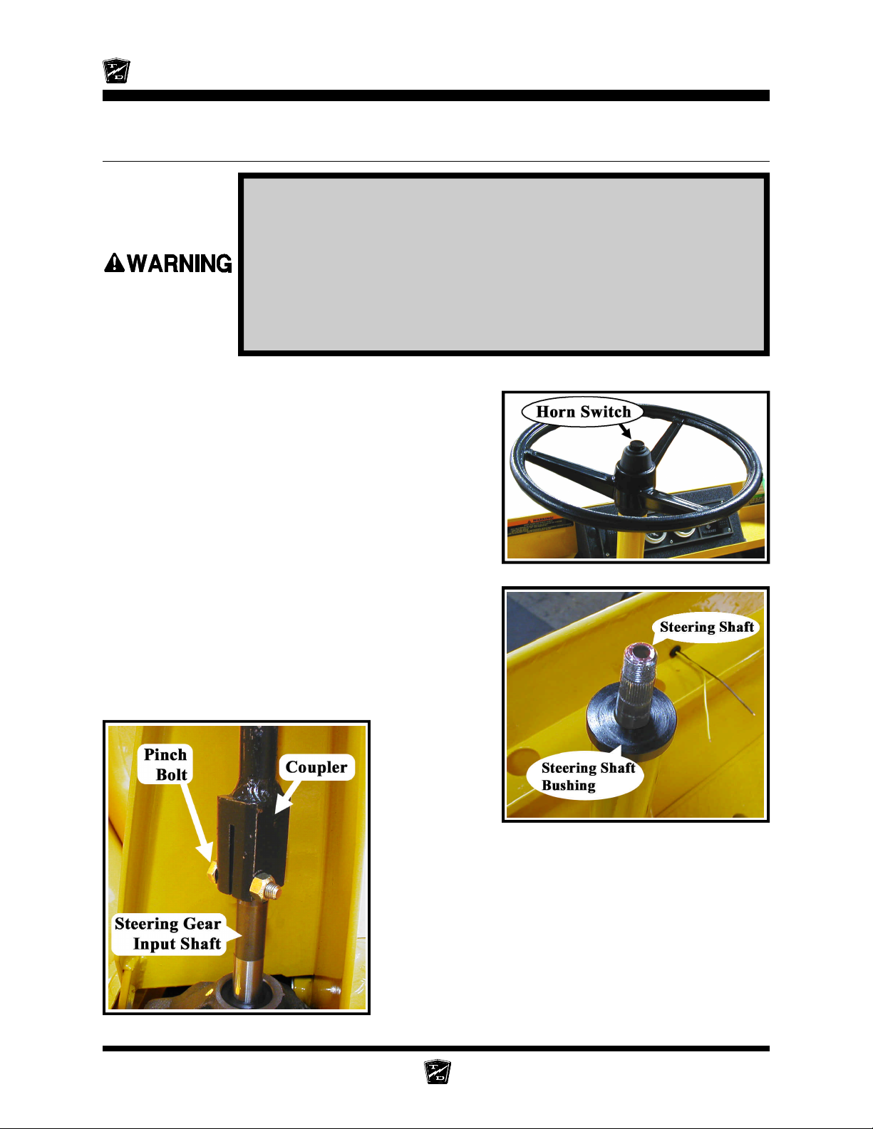
Maintenance, Service, and Repair
REPLACE THE STEERING SHAFT
1. Make sure the key-switch is in the “OFF” position, then remove the
key.
2. Place the forward-reverse switch in the center “OFF” position.
3. Set the park brake.
4. Place blocks under the front wheels to prevent vehicle movement.
5. Disconnect the main positive and negative cables at the batteries.
6. If equipped with a horn switch in the steering wheel, remove the switch, disconnect the wires
from the switch and cut the terminals off of the wires.
7. Remove the steering wheel.
NOTE: Refer to Replace the Steering Wheel
section for information regarding
removing the steering wheel.
8. Remove the upper steering shaft bushing or bearing
from the steering column.
9. Remove the steering gear access cover from the
steering column (if equipped).
10. Remove and discard the pinch bolt and nut from
the steering shaft coupler.
NOTE Most vehicle configurations will now allow the
steering shaft to slide off of the steering gear
input shaft and then back down out of the
steering column. If there is not enough
clearance for this procedure then the steering
gear must be removed. Refer to Replace the
Steering Gear for information regarding
removing the steering gear.
Steering Page 10
Page 65
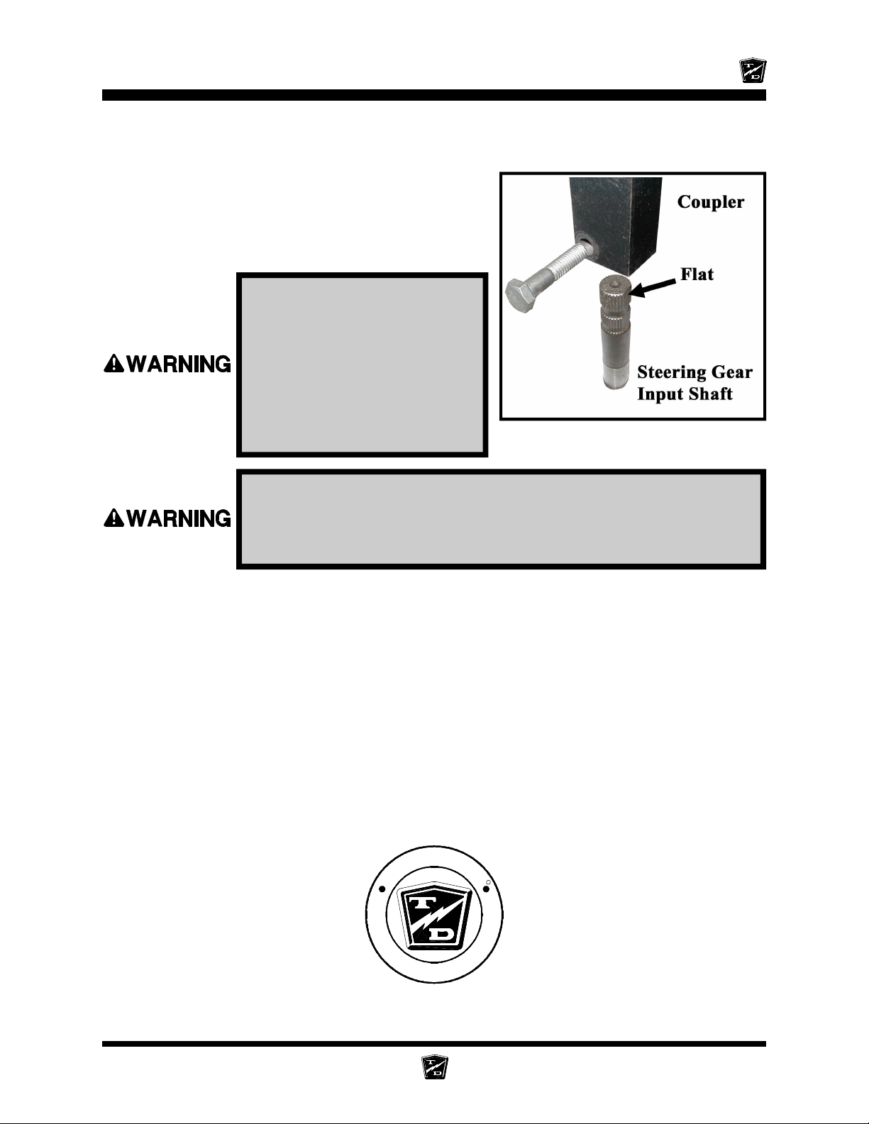
Maintenance, Service, and Repair
11. Remove the steering shaft from the vehicle.
12. Lightly grease the input shaft splines, steering wheel
splines and the upper steering shaft bushing.
13. Install the steering shaft in reverse order using a
new pinch bolt. Orientate the shaft so that the pinch
bolt is opposite the flat in the steering gear shaft.
See the illustration to the right.
Make sure that the pinch bolt
is not aligned with the flat on
the steering shaft. Aligning
the bolt with the flat could
result in failure of the steering
and loss of control of the
vehicle. This could lead to
property damage and/or
severe bodily injury.
Do not use the original pinch bolt and nut. Failure to replace the pinch
bolt and nut may result in failure of the steering causing loss of control
of the vehicle. This could lead to property damage and/or severe bodily
injury.
14. Tighten the pinch bolt to 24-26 ft-lbs.
15. Reconnect the main positive and negative cables at the batteries.
16. Remove the blocks from behind the wheels.
17. Release the parking brake and test drive the vehicle.
-
R
D
O
L
Y
A
T
T
h
e
B
e
s
t
W
a
y
T
o
U
N
N
R
s
s
e
n
i
s
u
B
r
u
o
Y
G
t
u
o
o
b
A
Steering Page 11
Page 66
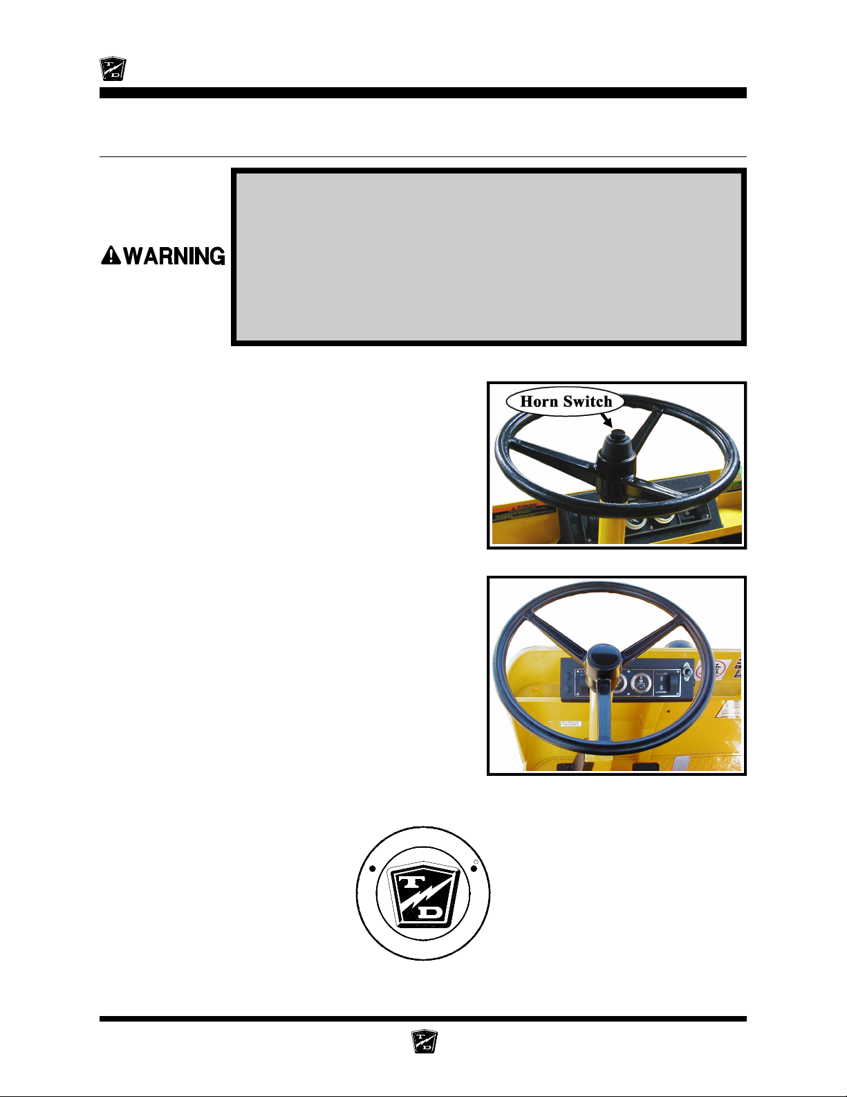
Maintenance, Service, and Repair
REPLACE THE STEERING WHEEL
1. Make sure the key-switch is in the “OFF” position, then remove the
key.
2. Place the forward-reverse switch in the center “OFF” position.
3. Set the park brake.
4. Place blocks under the front wheels to prevent vehicle movement.
5. Disconnect the main positive and negative cables at the batteries.
6. If equipped with a horn switch in the steering wheel, remove the switch and disconnect the wires
from the switch.
7. Remove the steering wheel nut.
8. Using a steering wheel puller, remove the steering
wheel.
9. Position the front wheels in the straight ahead
position.
10. Lightly grease the steering wheel splines and install
the replacement steering wheel orientated as shown
in the illustration to the right.
11. Tighten the steering wheel nut to 28-32 ft lbs.
12. Reinstall the horn switch (if equipped).
13. Reconnect the main positive and negative cables
at the batteries.
14. Remove the blocks from behind the wheels.
15. Release the parking brake and test drive the vehicle.
-
R
D
O
L
Y
A
T
T
h
e
B
e
s
t
W
a
y
T
o
U
N
N
o
Y
G
t
u
o
o
b
A
R
s
s
e
n
i
s
u
B
r
u
Steering Page 12
Page 67
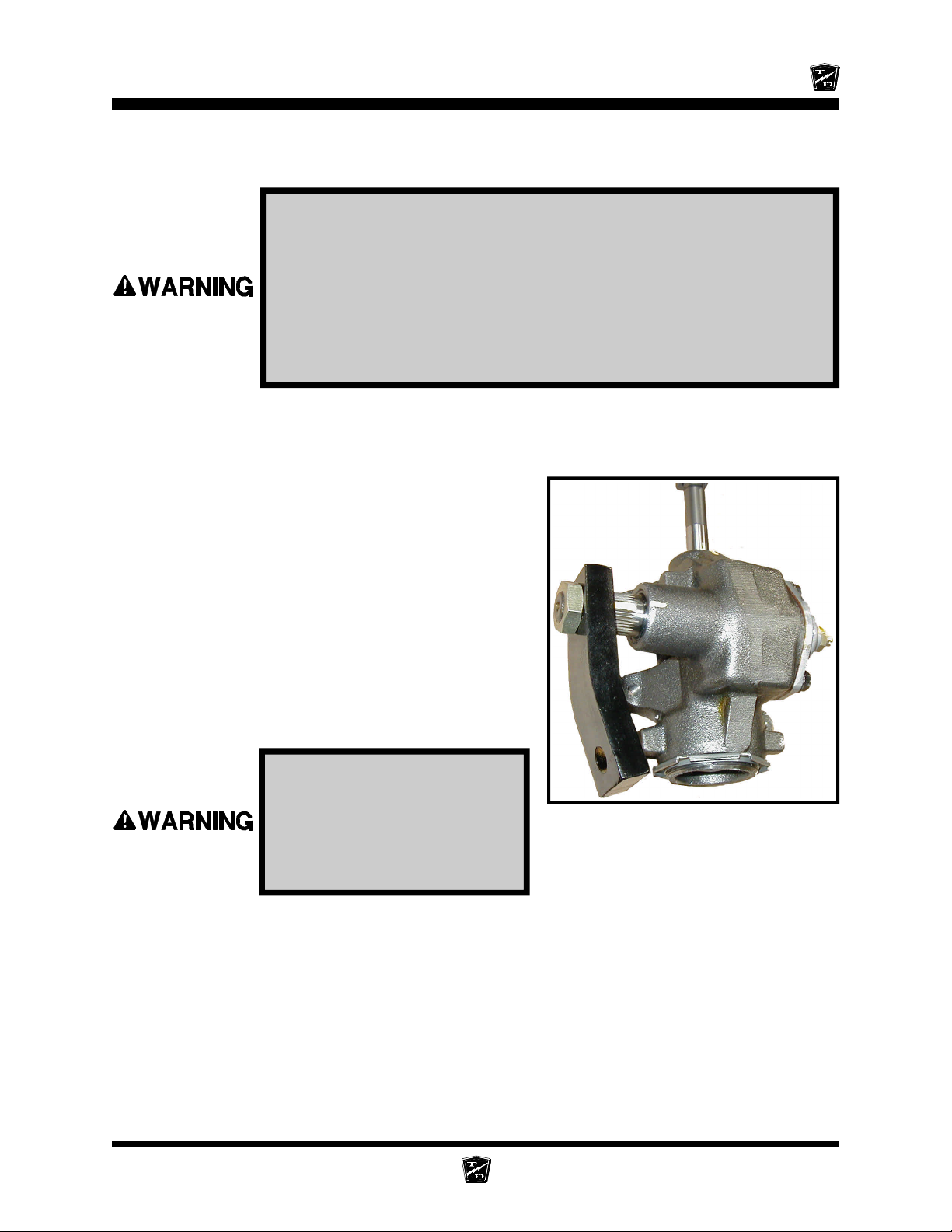
Maintenance, Service, and Repair
REPLACE THE STEERING GEAR
1. Make sure the key-switch is in the “OFF” position, then remove the
key.
2. Place the forward-reverse switch in the center “OFF” position.
3. Set the park brake.
4. Place blocks under the rear wheels to prevent vehicle movement.
5. Disconnect the main positive and negative cables at the batteries.
6. Remove the steering wheel. Refer to Replace the Steering Wheel section for information
regarding removing the steering wheel.
7. Remove the steering shaft. Refer to Replace the Steering Shaft section for information
regarding removing the steering shaft.
8. Remove the pitman arm using a pickle fork.
NOTE: On some vehicle configurations it may
be required to remove the drag link
from the pitman arm. Refer to Replace
the Ball Joints section for information
regarding removing the ball joint from
the pitman arm.
9. Support the steering gear so that it cannot fall out
of the vehicle.
10. Remove the bolts holding the steering gear to the
vehicle frame and remove the steering gear from
the vehicle.
Failure to support the
steering gear will result in
the steering gear falling out
of the vehicle and could
cause property damage and/
or severe bodily injury.
11. Center the steering gear. Refer to Center the Steering Gear section for information regarding
centering the steering gear.
12. Install in reverse order. Torque the pitman arm nut to 75-100 ft-lbs.
13. Reconnect the main positive and negative cables at the batteries.
14. Remove the blocks from behind the wheels.
15. Release the parking brake and test drive the vehicle.
Steering Gear with Pitman Arm
Steering Page 13
Page 68
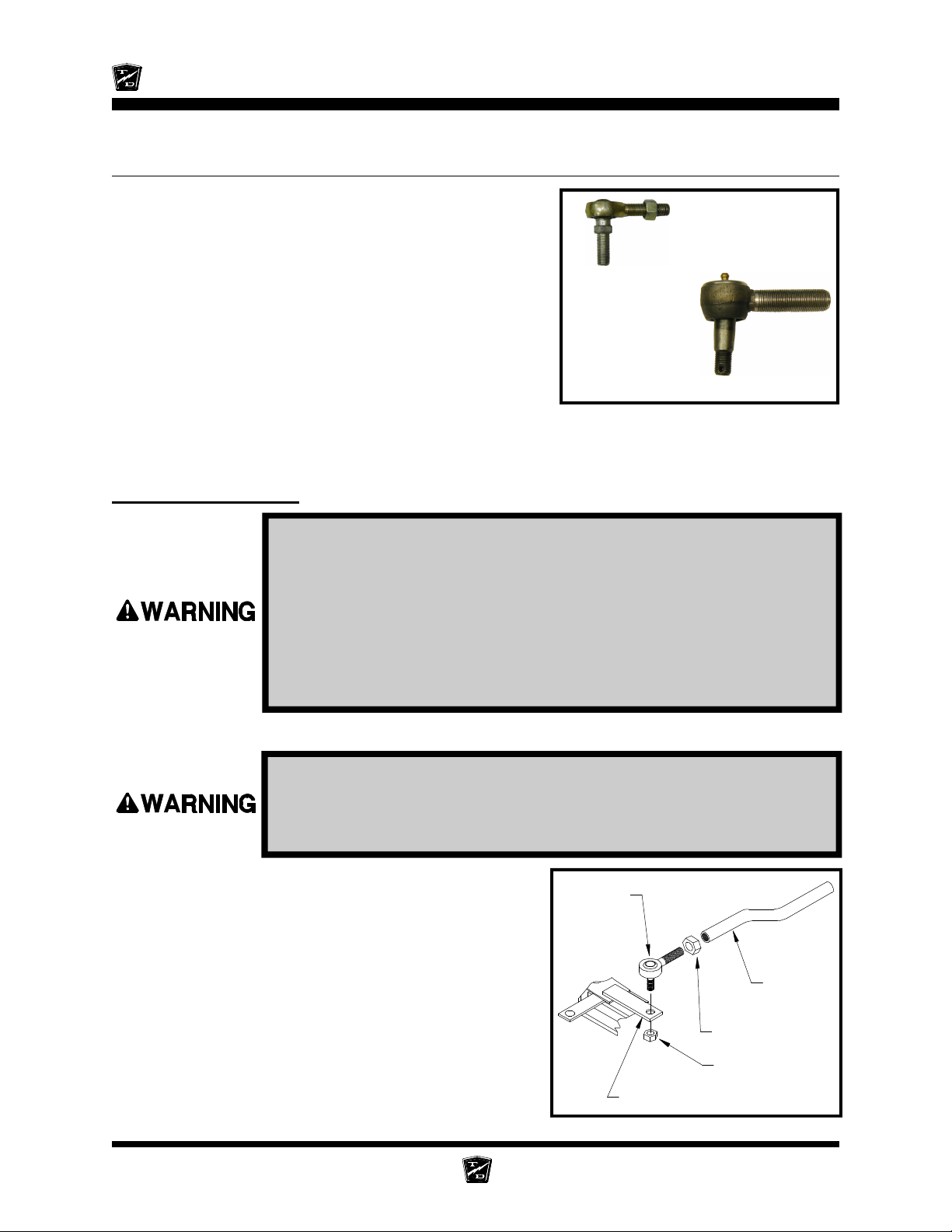
Maintenance, Service, and Repair
REPLACE THE BALL JOINTS, TIE RODS, AND DRAG LINK
This section will refer to two different types of ball joints. One
type is has a grease fitting and a tapered shaft where it is
installed on the steering arm or pitman arm. The second
cannot be greased and has a straight shaft. See the
illustrations to the right. Depending on the configuration of
your vehicle, it may be equipped one or both types of ball
joints.
Rod End
In this text:
The first type will be referred to as a “Ball Joint.”
The second type will be referred to as a “Rod End.”
NOTE: If a rod end or ball joint is worn out, we
recommend replacing all of the ball joints
and/or rod ends as a set.
Replacing a Rod End
1. Make sure the key-switch is in the “OFF” position, then remove the
key.
2. Place the forward-reverse switch in the center “OFF” position.
3. Set the park brake.
4. Place blocks under the rear wheels to prevent vehicle movement.
5. Disconnect the main positive and negative cables at the batteries.
6. Raise the front of the vehicle and support with jack stands.
Always use a lifting strap, hoist, and jack stands, of adequate capacity
to lift and support the vehicle. Failure to use lifting and support devices
of rated load capacity may result in severe bodily injury.
Ball Joint
7. Loosen the rod end jam nut or clamp on the steering
sleeve.
8. Remove the rod end nut.
9. Remove the rod end from the steering arm.
HINT: Count the number of turns required to
remove the rod end from the steering
sleeve. This will make it easier to
realign the wheels.
Steering Page 14
Rod End
Steering
Sleeve
Jam Nut
Rod End Nut
Steering Arm
Page 69
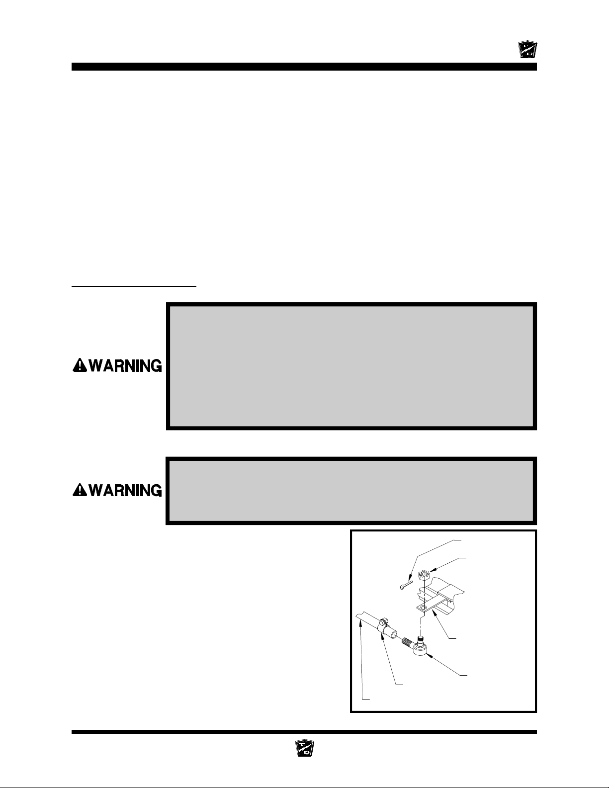
10. Install the new rod end into the steering sleeve. Screw it into the sleeve the same number of
turns counted in the previous step. Do not tighten the rod end clamp or jam nut at this time.
11. Install the rod end into the steering arm. Tighten the rod end nut to 20-25 ft-lbs.
12. Realign the front wheels.
NOTE: Refer to the Steering section for information regarding realignment
of the front wheels.
13. Lower the vehicle.
14. Reconnect the main positive and negative cables at the batteries.
15. Remove the blocks from behind the wheels.
16. Release the park brake and test drive the vehicle.
Replacing a Ball Joint
1. Make sure the key-switch is in the “OFF” position, then remove the
Maintenance, Service, and Repair
key.
2. Place the forward-reverse switch in the center “OFF” position.
3. Set the park brake.
4. Place blocks under the rear wheels to prevent vehicle movement.
5. Disconnect the main positive and negative cables at the batteries.
6. Raise the front of the vehicle and support with jack stands.
Always use a lifting strap, hoist, and jack stands, of adequate capacity
to lift and support the vehicle. Failure to use lifting and support devices
of rated load capacity may result in severe bodily injury.
7. Loosen the ball joint clamp on the steering sleeve.
8. Remove the cotter pin and ball joint nut.
9. Using a pickle fork, remove the ball joint from the
steering arm.
10. Remove the ball joint from the steering sleeve.
HINT: Count the number of turns required to
remove the ball joint from the sleeve.
This will make it easier to realign the
wheels.
Cotter Pin
Ball Joint Nut
Steering Arm
11. Install the new ball joint into the steering sleeve.
Screw it into the sleeve the same number of turns
counted in the previous step. Do not tighten the ball
joint clamp at this time.
Steering Page 15
Clamp
Ball Joint
Steering Sleeve
Page 70
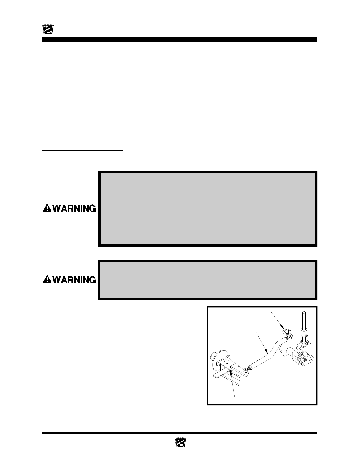
Maintenance, Service, and Repair
Pitman Arm
12. Install the ball joint into the steering arm. Tighten the ball joint nut to 40-45 ft-lbs. and install a new
cotter pin.
13. Realign the front wheels.
NOTE: Refer to the Steering section for information regarding realignment
of the front wheels.
14. Lower the vehicle.
15. Reconnect the main positive and negative cables at the batteries.
16. Remove the blocks from behind the wheels.
17. Release the park brake and test drive the vehicle.
Replacing the Drag Link
The Drag Link is the linkage that connects the steering gear pitman arm to the steering knuckle. Refer to
the illustration on the following page.
1. Make sure the key-switch is in the “OFF” position, then remove the
key.
2. Place the forward-reverse switch in the center “OFF” position.
3. Set the park brake.
4. Place blocks under the rear wheels to prevent vehicle movement.
5. Disconnect the main positive and negative cables at the batteries.
6. Raise the front of the vehicle and support with jack stands.
Always use a lifting strap, hoist, and jack stands, of adequate capacity
to lift and support the vehicle. Failure to use lifting and support devices
of rated load capacity may result in severe bodily injury.
7. Remove the ball joints or rod ends from the steering
knuckle and pitman arm.
NOTE: Refer to the Replacing the Ball
Joints section for information
regarding the removal of the ball joints
or rod ends.
8. Remove the drag link as an assembly.
9. Install in reverse order.
Drag Link
10. Realign the front wheels.
NOTE: Refer to the Steering section for
information regarding realignment of
the front wheels.
Steering Knuckle
Typical Drag Link
Steering Page 16
Page 71
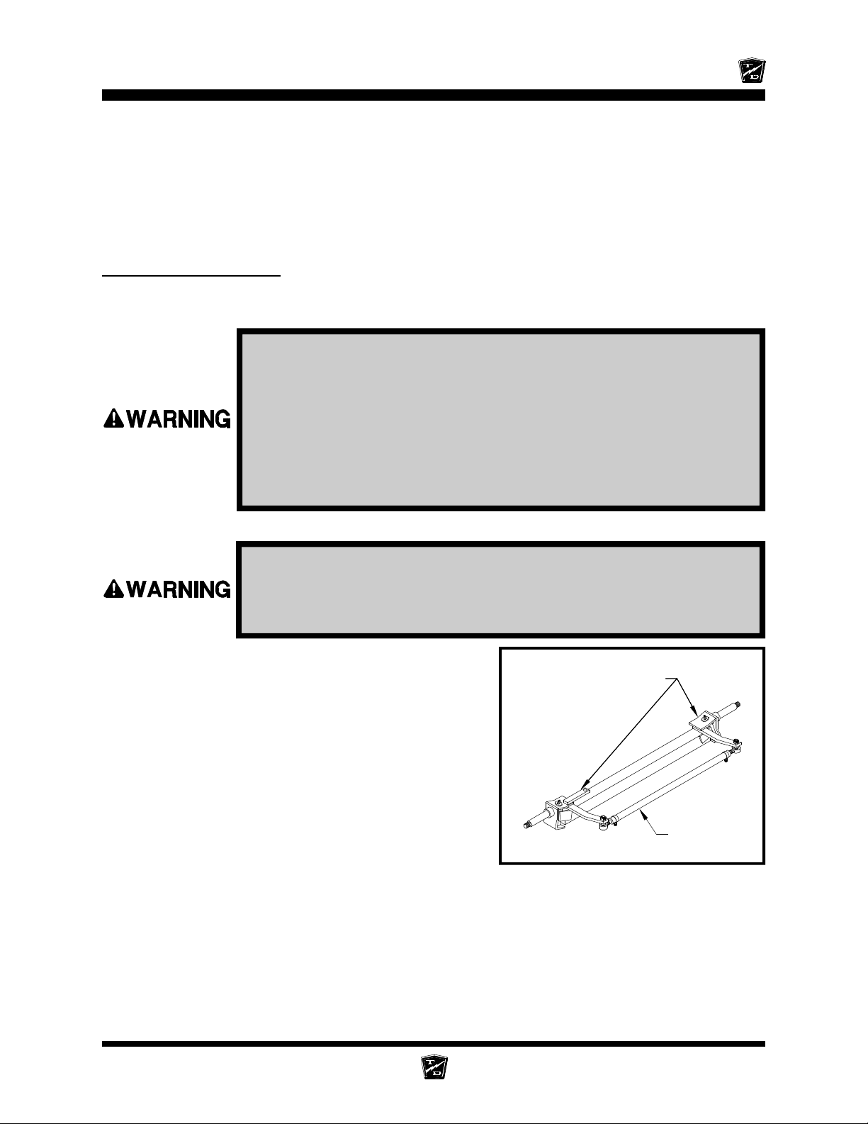
Maintenance, Service, and Repair
Tie Rod
11. Lower the vehicle.
12. Reconnect the main positive and negative cables at the batteries.
13. Remove the blocks from behind the wheels.
14. Release the park brake and test drive the vehicle.
Replacing the Tie Rod
The Tie Rod is the linkage that connects the two steering knuckles together. Refer to the illustration
below..
1. Make sure the key-switch is in the “OFF” position, then remove the
key.
2. Place the forward-reverse switch in the center “OFF” position.
3. Set the park brake.
4. Place blocks under the rear wheels to prevent vehicle movement.
5. Disconnect the main positive and negative cables at the batteries.
6. Raise the front of the vehicle and support with jack stands.
Always use a lifting strap, hoist, and jack stands, of adequate capacity
to lift and support the vehicle. Failure to use lifting and support devices
of rated load capacity may result in severe bodily injury.
7. Remove the ball joints or rod ends from the steering
knuckles.
NOTE: Refer to the Replacing the Ball
Steering Knuckle
Joints section for information
regarding the removal of the ball joints
or rod ends.
8. Remove the tie rod as an assembly.
9. Install in reverse order.
10. Realign the front wheels.
NOTE: Refer to the Steering section for
information regarding realignment of
the front wheels.
11. Lower the vehicle.
12. Reconnect the main positive and negative cables at the batteries.
Typical Front Axle Assembly
13. Remove the blocks from behind the wheels.
14. Release the park brake and test drive the vehicle.
Steering Page 17
Page 72
Maintenance, Service, and Repair
CENTER THE STEERING GEAR
1. Remove the pitman arm.
2. Rotate the input shaft clockwise until it stops.
3. While counting the rotations, rotate the input shaft counter clockwise until it stops.
4. Rotate the input shaft clockwise 1/2 the rotations counted in the previous step.
5. Mark the steering gear input shaft and pitman shaft in relation to the housing for reference.
PITMAN SHAFT ALIGNMENT
1. Make sure the key-switch is in the “OFF” position, then remove the
key.
2. Place the forward-reverse switch in the center “OFF” position.
3. Set the park brake.
4. Place blocks under the rear wheels to prevent vehicle movement.
5. Disconnect the main positive and negative cables at the batteries.
6. Raise the front of the vehicle and support with jack stands.
Always use a lifting strap, hoist, and jack stands, of adequate capacity
to lift and support the vehicle. Failure to use lifting and support devices
of rated load capacity may result in severe bodily injury.
7. Center the steering gear. Refer to Center the Steering Gear section for information regarding
centering the steering gear.
8. Screw both steering stops all of the way in.
9. Install the pitman arm so that it is centered between the steering stops.
10. Realign the front wheels. Refer to Front End Alignment section for information regarding
aligning the front wheels.
11. Adjust the steering stops so that the front wheels do not contact any part of the frame, suspension
or steering linkages and the left and right turning radiuses are equal.
12. Tighten the steering stop jam nuts.
13. Lower the vehicle.
14. Reconnect the main positive and negative cables at the batteries.
15. Remove the blocks from behind the wheels.
16. Release the park brake and test drive the vehicle.
Steering Page 18
Page 73
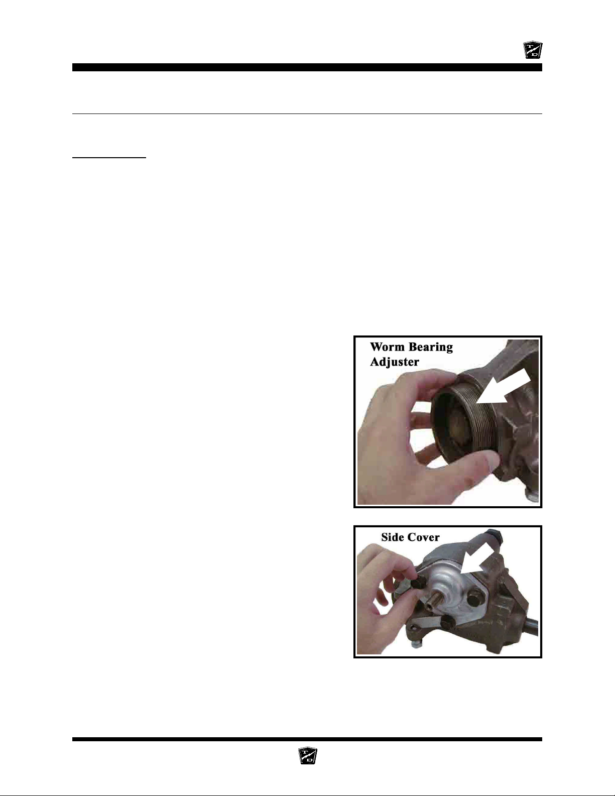
Maintenance, Service, and Repair
REPAIR THE STEERING GEAR
Disassembly
NOTE: The steering gear must be removed from the vehicle for this
procedure. Refer to Replace the Steering Gear section for
information regarding removing the steering gear.
NOTE: The steering gear is packed with grease. Only perform maintenance
on the steering gear in an area that will contain any grease that
may spill out of the steering gear when it is disassembled.
Refer to the illustration at the end of this section for a blown up view of the steering gear assembly.
1. Center the steering gear.
A. Turn the steering shaft all of the way in one direction.
B. While counting the rotation, turn the steering shaft all of the way in the opposite direction.
C. Turn the steering shaft 1/2 the number of turns in the original direction.
2. Remove the worm bearing adjuster locking ring and
the worm bearing adjuster.
3. Remove the side cover/pitman shaft assembly by
removing the three side cover bolts and then pulling
the assembly out of the housing.
NOTE: The side cover/pitman shaft assembly
normally does not have to be
disassembled.
Steering Page 19
Page 74
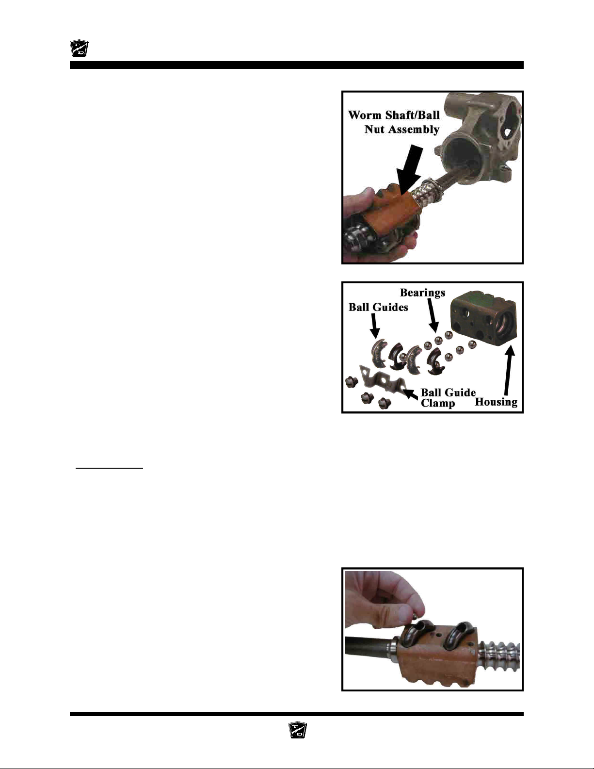
Maintenance, Service, and Repair
4. Remove the worm shaft and ball nut assembly from
the bottom of the housing.
5. Remove the worm shaft seal.
6. Remove the pitman shaft seal.
7. Remove the upper worm bearing and bearing cup
from the housing.
8. The ball nut assembly consists of two sets of ball
bearings that recirculate in two channels in the ball
nut housing. The bearings may fall out once the
bearing guides are removed. Be careful not to lose
any of the bearings.
9. Remove the ball guide clamps, ball guides and all
of the ball bearings.
10. Remove the ball nut from the worm shaft.
11. Thoroughly clean and inspect all parts for signs of
corrosion, damage or wear and replace as required.
Reassembly
1. Lightly lubricate all parts before reassembly.
2. Install a new worm shaft seal and pitman shaft seal into the housing.
3. Install the upper worm bearing cup.
4. Divide the ball bearing into two equal groups.
5. Position the ball nut onto the worm as shaft as shown in the illustration.
6. Insert the ball guides into the ball nut.
7. Insert each group of bearings into the ball guides.
NOTE: Do not rotate the worm shaft while
installing the bearings. This may
cause one or more of the bearings to
enter the crossover passage in the
ball nut, causing improper operation.
8. Install the ball guide clamp.
Steering Page 20
Page 75
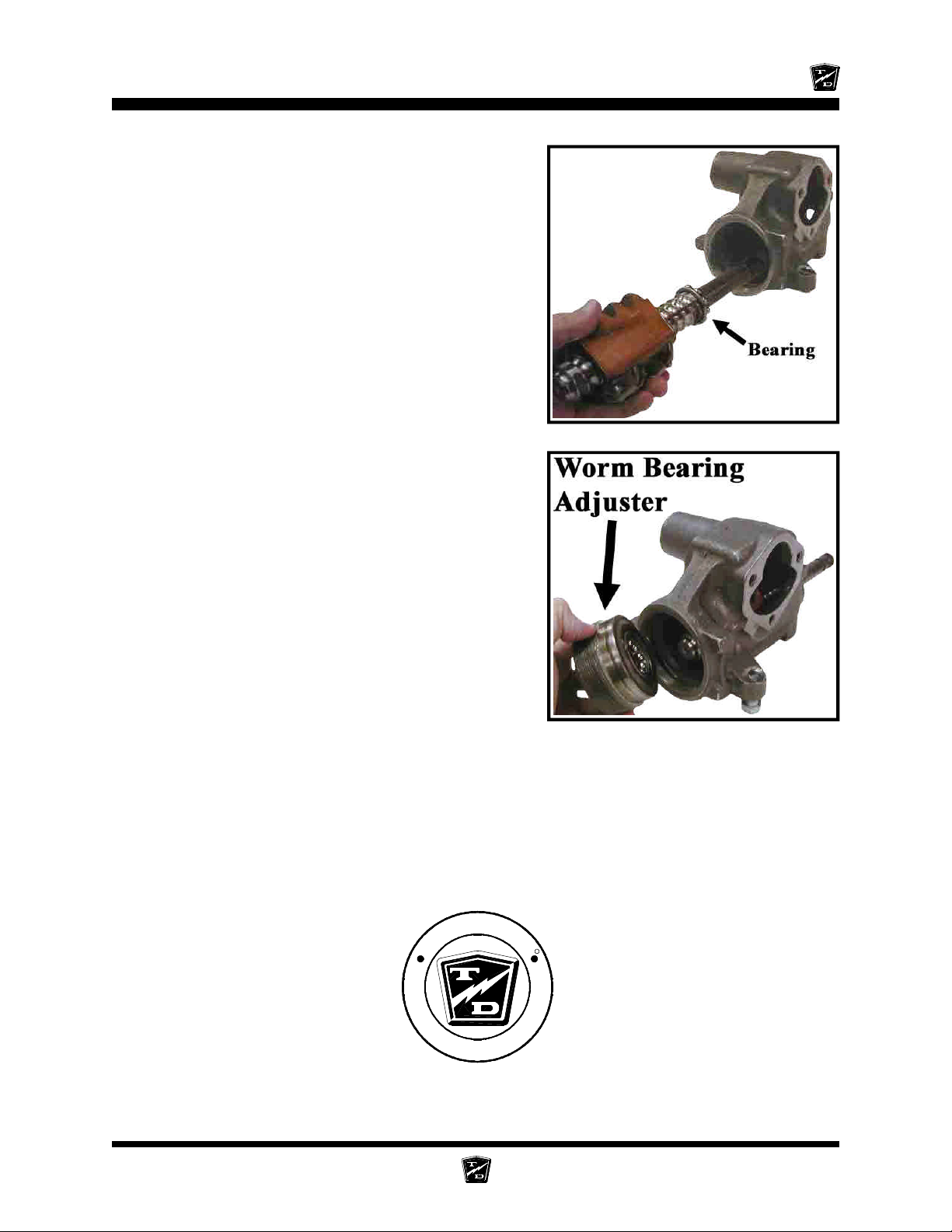
Maintenance, Service, and Repair
9. Place the upper worm bearing on the worm shaft
and install the worm shaft/ball nut assembly into
the housing being careful not to damage the worm
shaft seal.
10. Install the assembled worm bearing adjuster into
the housing and tighten just enough to remove all
play in the worm shaft.
11. Install, but do not tighten the worm bearing adjuster
lock nut.
12. Rotate the worm shaft to center the ball nut in the
housing.
13. Place a new gasket onto the housing and install
the assembled pitman shaft/side cover onto the
housing using two of the three mounting bolts.
14. Pack the steering gear with grease through the open
side cover bolt hole and then install the bolt.
15. Adjust the steering gear.
NOTE: Refer to Adjust the Steering gear
section for information regarding
adjusting the steering gear.
16. Once the adjustments are completed, make sure that the locking ring and jam nut are tight.
-
R
D
O
L
Y
A
T
T
h
e
B
e
s
t
W
a
y
T
o
U
N
N
R
s
s
e
n
i
s
u
B
r
u
o
Y
G
t
u
o
o
b
A
Steering Page 21
Page 76
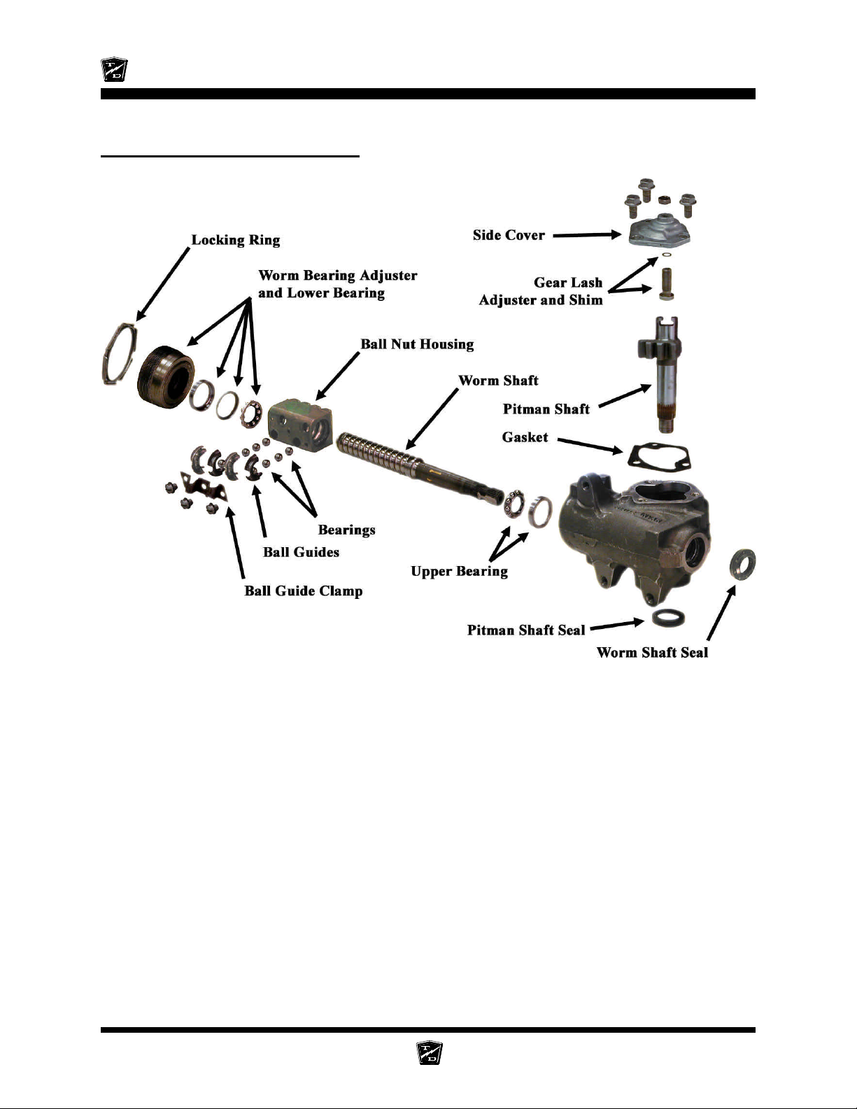
Maintenance, Service, and Repair
Exploded View of Steering Gear
Steering Page 22
Page 77
Brake Service
TABLE OF CONTENTS
Inspect the Service Brake .............................2
Disc Brake Pads ...................................................... 2
Disc Brake Rotor .....................................................3
Inspect the Parking brake .............................4
Wheel Park Brake (hydraulic disc) ......................... 4
Electric Motor Brake ................................................ 5
Adjust the Service Brakes ............................6
Two or Four Wheel Hydraulic Disc Brakes ............6
Adjust the Parking Brake ..............................7
Wheel Park Brake (hydraulic disc) ......................... 7
Check Master Cylinder Fluid ........................8
Bleed the Brake System................................9
Flush the Brake System ................................11
Replace the Parking Brake Lining
(electric motor brake) .............................12
Inspection:................................................................ 14
Replace Front Disc Brake Pads....................15
Replace Rear Brake Pads .............................17
Hydraulic Disc .......................................................... 17
Replace the Wheel Cylinder..........................19
Disc Brake Body Assembly (front or rear) ..............19
Repair the Brake Body ..................................21
Replace the Master Cylinder.........................23
Repair the Master Cylinder ...........................25
Page 78
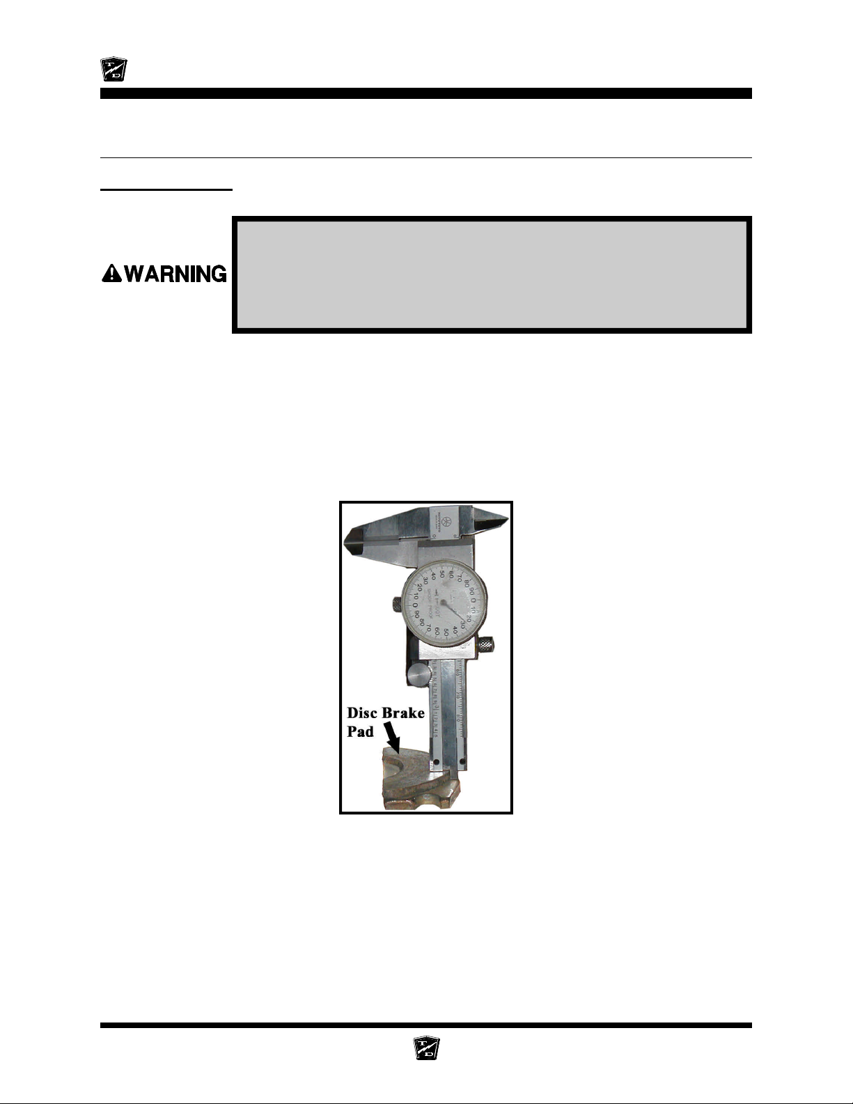
Maintenance, Service, and Repair
INSPECT THE SERVICE BRAKE
Disc Brake Pads
Current Taylor-Dunn® brakes are asbestos free. However, there is the
possibility that the original brakes were replaced with aftermarket
parts containing asbestos. Since this possibility exists, all brake parts
should be handled as if they contain asbestos. Refer to Appendix C for
recommended handling precautions.
NOTE: The brake pad must be removed to accurately measure the lining
thickness. Refer to Replace the Front or Rear Brake Pads section
for information on removing the brake pads.
Measure the brake pad lining at the thinnest point on the pad. If the brake pad lining is 1/16-inch or less
then the brake pad must be replaced.
It is recommended to replace the left and right side brake pads as a set.
Brakes Page 2
Page 79
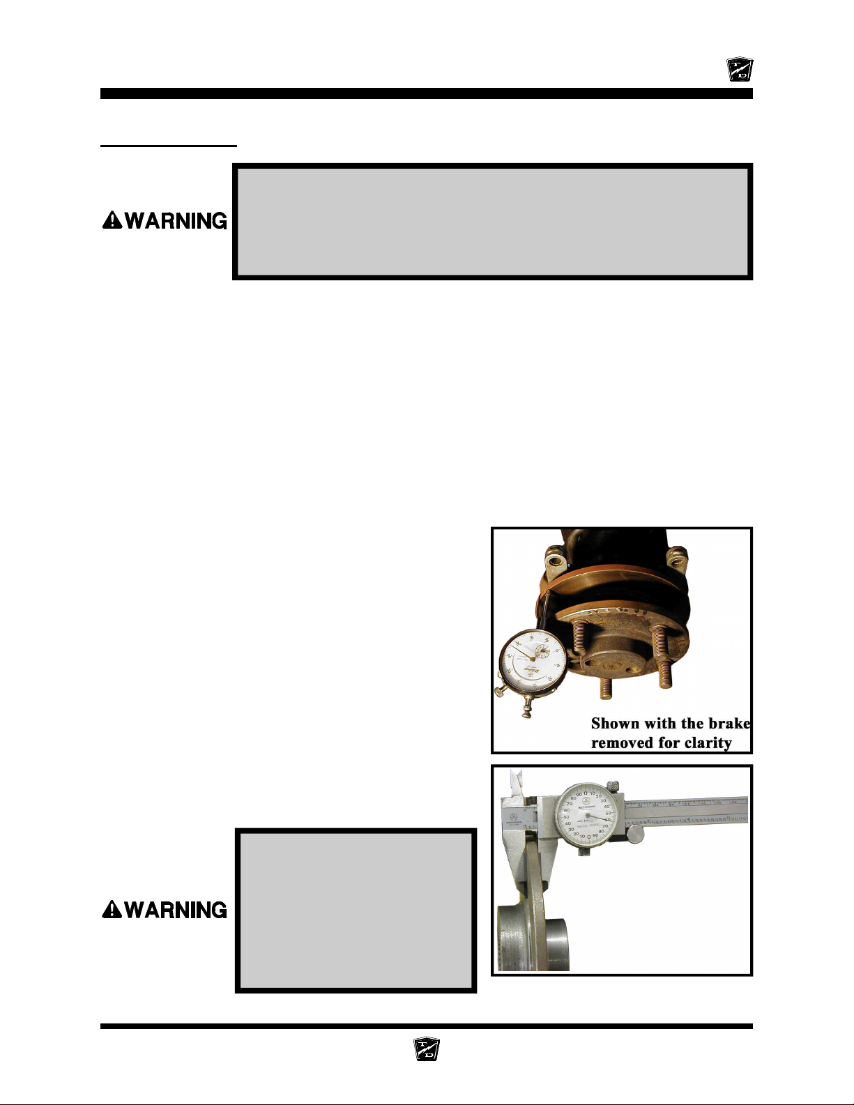
Disc Brake Rotor
NOTE: The front brake rotor is an integral part of the front hub. If the brake
NOTE: Depending on the rear axle configuration, the rear brake rotor may
NOTE: The wheel must be removed to accurately measure the rotor
Maintenance, Service, and Repair
Current Taylor-Dunn® brakes are asbestos free. However, there is
the possibility that the original brakes were replaced with aftermarket
parts containing asbestos. Since this possibility exists, all brake parts
should be handled as if they contain asbestos. Refer to Appendix C for
recommended handling precautions.
rotor is worn beyond its service limits, then the front hub must be
replaced. Refer to Front Axle Service for information on replacing
the front hub.
be an integral part of the rear axle. If the brake rotor is worn beyond
its service limits, then the rear axle must be replaced. Refer to
Transmission section for information regarding replacing the rear
axle
thickness. Refer to Tires and Wheels section for information on
removing the wheel.
1. Measure the run out of the rotor at its maximum
diameter. If the run out exceeds 0.005, then the rotor
must be machined. Do not machine the rotor beyond
its service limits.
NOTE: A bent axle or damaged rear axle could
cause excessive brake rotor run out.
2. Measure the thickness of the brake rotor in 3 places.
If the brake rotor thickness is less than 0.20-inches,
then the rotor must be replaced.
Do not use a rotor that is
worn beyond its service
limits. A rotor worn beyond
its service limits could fail
and cause loss of brakes
resulting in severe bodily
injury and/or property
damage.
Rotor removed for clarity. The rotor does not
have to be removed for this procedure.
Brakes Page 3
Page 80
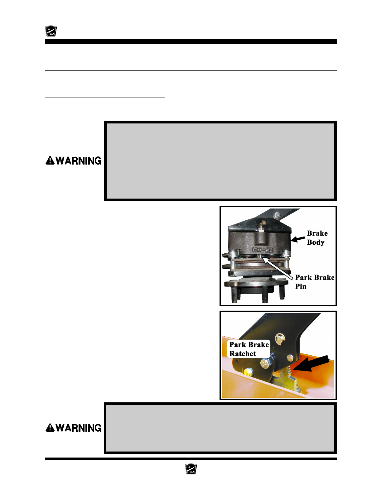
Maintenance, Service, and Repair
INSPECT THE PARKING BRAKE
Wheel Park Brake (hydraulic disc)
NOTE: The parking brake is actuated through a pin in the center of the
rear left and right brake body on the rear axles.
1. Make sure the key-switch is in the “OFF” position, then remove the
key.
2. Place the forward-reverse switch in the center “OFF” position.
3. Set the park brake.
4. Place blocks under the front wheels to prevent vehicle movement.
5. Disconnect the main positive and negative cables at the batteries.
6. Release the park brake.
7. Inspect the brake pads. Refer to Inspect the
Service Brake section to inspect the brake pads.
8. Inspect the park brake pin and bushing for any signs
of damage or corrosion.
NOTE: The park brake pin is inside of the
brake body. Refer to Repair the Brake
Body for information on removing the
park brake pin.
9. Inspect all brake cables and linkages for any signs
of damage, wear, or missing cotter pins.
10. Inspect the brake handle locking mechanism for any
signs of damage.
NOTE: Refer to Adjust the Parking Brake
section for information regarding
adjusting the parking brake.
If any sign of damage or wear is found on the locking mechanism,
cables, or linkages then they must be repaired or replaced
immediately. Failure to repair or replace any damaged component
could result in failure of the park brake causing property damage
and/or severe bodily injury.
Brakes Page 4
Page 81
Maintenance, Service, and Repair
Electric Motor Brake
A variable power supply capable of supplying 0-volts to 24-volts DC at 2-Amps will be required to perform
the testing.
The brake does not have to be removed from the transmission for this test.
1. Make sure the key-switch is in the “OFF” position, then remove the
key.
2. Place the forward-reverse switch in the center “OFF” position.
3. If equipped with a hand or foot park brake, set the park brake.
4. Place blocks under the front wheels to prevent vehicle movement.
5. Disconnect the main positive and negative cables at the batteries.
6. Disconnect the electric brake connector from the vehicles harness.
7. Adjust the power supply to zero volts.
8. Connect the power supply to the electric brake.
9. Slowly increase the voltage until you hear a ‘click’ from the brake. The ‘click’ is the brake releasing.
The motor should now be free to rotate limited by the gear train and parking brake).
a) If the brake does not release until the voltage exceeds 18-volts, then the friction plate has
worn beyond its service limits and must be replaced.
b) If the brake does not release at all, then the brake electromagnet has failed and must be
replaced.
10.Reconnect the electric brake.
11. Reconnect the main positive and negative cables at the batteries.
12.Remove blocks from behind the wheels.
13.Release the parking brake and test drive the vehicle.
-
R
D
O
L
Y
A
T
T
h
e
B
e
s
t
W
a
y
T
o
U
N
Y
G
t
u
o
o
b
A
Brakes Page 5
N
R
s
s
e
n
i
s
u
B
r
u
o
Page 82
Maintenance, Service, and Repair
ADJUST THE SERVICE BRAKES
Two or Four Wheel Hydraulic Disc Brakes
The hydraulic disc brake system is automatically adjusted. A low brake pedal or lack of braking power
could be caused by:
• Brake fluid level low in the master cylinder. See Check the Master Cylinder Fluid section.
• Air in the brake lines. See Bleed the Brakes section.
• Worn brake pads. See Inspect the Service Brake section.
• Worn brake rotor. See Inspect the Service Brake section.
• Binding brake pedal linkage.
If you are experiencing a low brake pedal or lack of braking power, the entire brake system should be
inspected.
-
R
D
O
L
Y
A
T
T
h
e
B
e
s
t
W
a
y
T
o
G
U
N
N
R
s
s
e
n
i
s
u
B
r
u
o
Y
t
u
o
o
b
A
Brakes Page 6
Page 83
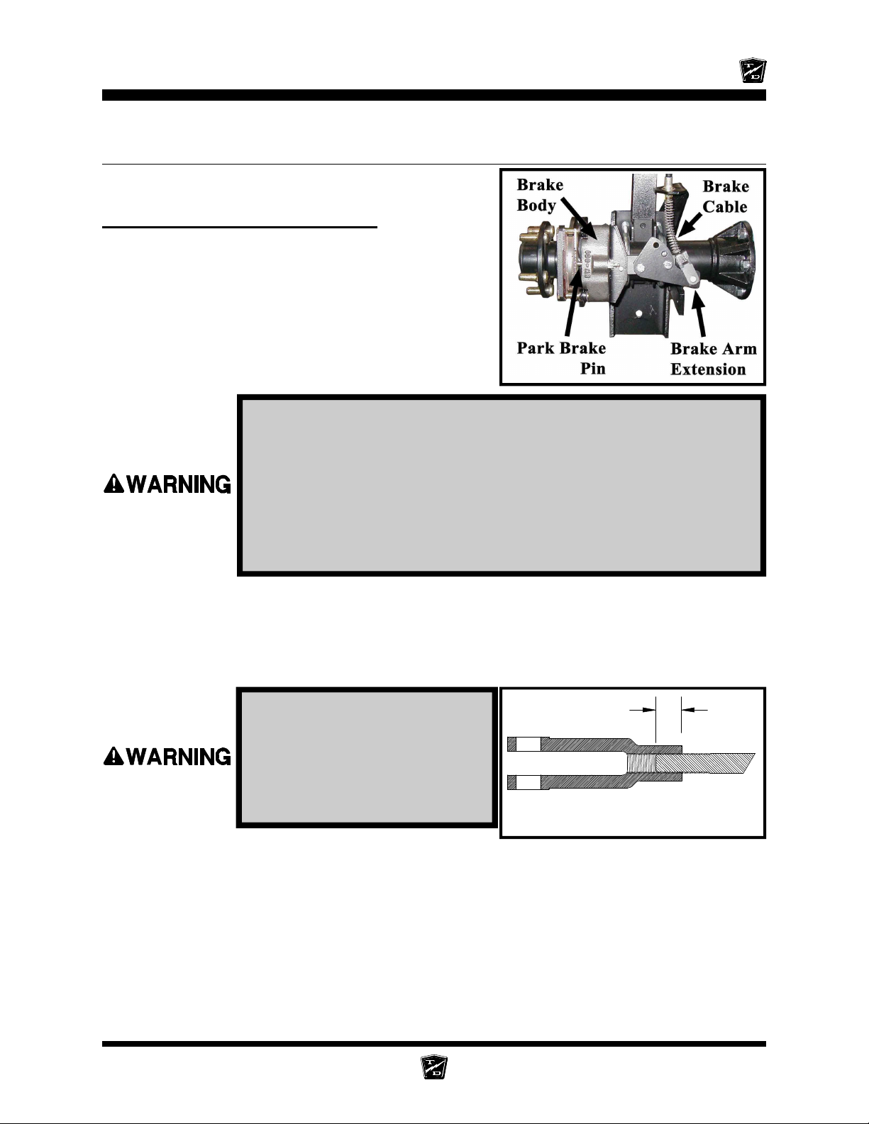
Maintenance, Service, and Repair
3/8 Min.
ADJUST THE PARKING BRAKE
Wheel Park Brake (hydraulic disc)
The parking brake is actuated through a pin in the center of
the rear left and right brake body on the rear axles.
1. Make sure the key-switch is in the “OFF” position, then remove the
key.
2. Place the forward-reverse switch in the center “OFF” position.
3. Set the park brake.
4. Place blocks under the front wheels to prevent vehicle movement.
5. Disconnect the main positive and negative cables at the batteries.
6. Release the park brake.
7. Loosen the jam nuts on the Primary Adjustment Rod.
8. Tighten the Primary Adjustment Rod until it is difficult to rotate the brake arm clevis pin on both
wheels.
9. Loosen the Primary adjustment rod one to two turns so that both wheels rotate whith no brake
drag.
The threaded rod must be
screwed into the clevis with at
least 3/8” of threads. Less than
3/8” of threads in a clevis could
result in brake failure causing
severe bodily injury and/or
property damage.
Cutaway of Clevis and Threaded Rod
NOTE: If there is no adjustment left in the Primary Adjustment Rod, then
the Brake Arm Extension must be rotated to engage the next hole
in the arm.
10.Tighten the jam nuts on the park brake linkage.
11. Set the park brake.
12.Reconnect the main positive and negative cables at the batteries.
13.Remove blocks from behind the wheels.
14.Release the park brake and test drive the vehicle.
Brakes Page 7
Page 84
Maintenance, Service, and Repair
CHECK MASTER CYLINDER FLUID
Do not ingest brake fluid or allow contact with skin or eyes. Always
wear protective clothing and a face shield when working with or
around brake fluid.
SKIN CONTACT
Flush area immediately with water for several minutes. If a rash or
skin irritation develops, get medical attention immediately.
EYE CONTACT
Immediately flush the eye with water for 15 minutes and call
physician.
INGESTION
Get medical attention immediately.
1. Make sure the key-switch is in the “OFF” position, then remove the
key.
2. Place the forward-reverse switch in the center “OFF” position.
3. Set the park brake.
4. Place blocks under the front wheels to prevent vehicle movement.
5. Disconnect the main positive and negative cables at the batteries.
6. Thoroughly clean the area around the master cylinder cap.
7. Remove the master cylinder cap.
8. If the fluid in the master cylinder is contaminated then the entire brake system must be flushed.
Refer to Bleed the Brakes for information regarding flushing the brake system.
9. Fill with brake fluid from a new sealed container to within 1/4-inch of the top of the master
cylinder chamber and reinstall the cap.
10. Reconnect the main positive and negative cables at the batteries.
11. Remove blocks from behind the wheels.
12. Release the parking brake and test drive the vehicle.
• Only use DOT 3 brake fluid from a new sealed container.
• DOT 3 brake fluid is corrosive and will damage paint finishes.
• Dispose of brake fluid in accordance with local state and federal
regulations.
• Read and follow all warnings on the brake fluid container.
Brakes Page 8
Page 85
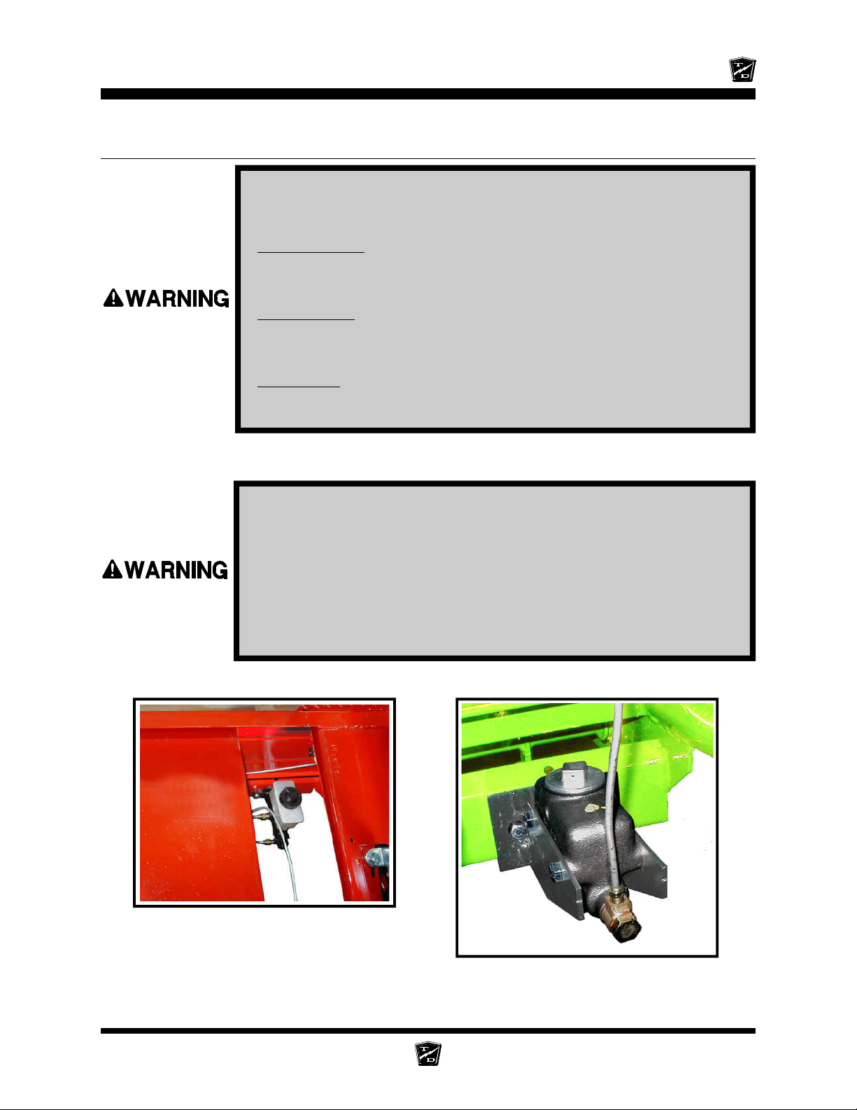
Maintenance, Service, and Repair
BLEED THE BRAKE SYSTEM
Do not ingest brake fluid or allow contact with skin or eyes. Always
wear protective clothing and a face shield when working with or
around brake fluid.
SKIN CONTACT
Flush area immediately with water for several minutes. If a rash or
skin irritation develops, get medical attention immediately.
EYE CONTACT
Immediately flush the eye with water for 15 minutes and call
physician.
INGESTION
Get medical attention immediately.
NOTE: Start this procedure at the wheel furthest from the master cylinder,
then work toward the wheel closest to the master cylinder.
1. Make sure the key-switch is in the “OFF” position, then remove the
key.
2. Place the forward-reverse switch in the center “OFF” position.
3. Set the park brake.
4. Place blocks under the front wheels to prevent vehicle movement.
5. Disconnect the main positive and negative cables at the batteries.
6. Thoroughly clean the area around the master cylinder cap and remove the cap.
Master cylinder is located between the front
seats. Dual reservoir shown.
Brakes Page 9
Single reservoir master cylinder
Page 86
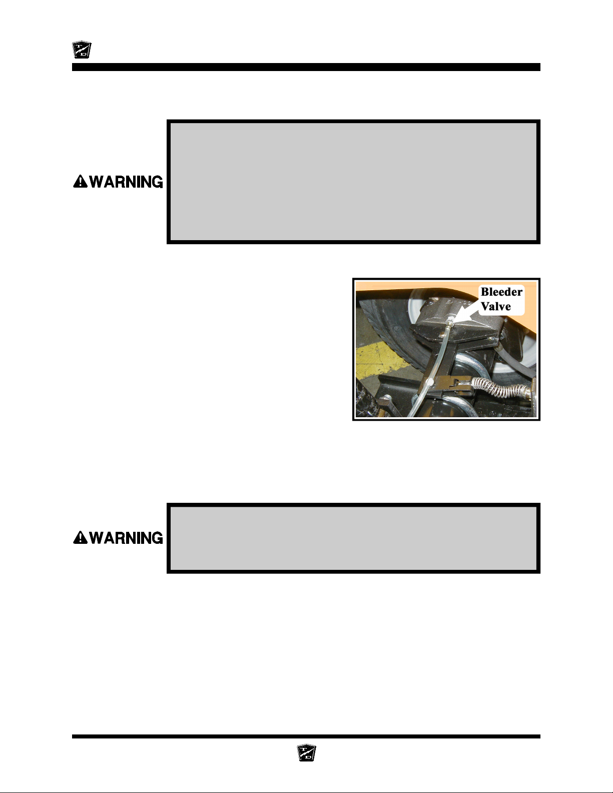
Maintenance, Service, and Repair
7. Add brake fluid from a new sealed container to the master cylinder. Fill to 1/4” from the top of the
master cylinder chamber.
• Only use DOT 3 brake fluid from a new sealed container.
• DOT 3 brake fluid is corrosive and will damage paint finishes.
• Dispose of brake fluid in accordance with local state and federal
regulations.
• Read and follow all warnings on the brake fluid container.
8. The master cylinder fluid level will drop as the brakes are bled. Periodically check and fill the
master cylinder during this procedure. Do not allow the fluid level in the master cylinder to drop
too low as this will allow air into the brake lines.
9. Attach a clear hose to the bleeder valve on the brake
cylinder that is to be bled. Route the hose into a
clear container for waste brake fluid.
10. Pump the brake pedal a few times and then press
and hold light pressure to the brake pedal.
11. Open the bleeder valve on the hydraulic brake body.
12. Depress the foot pedal to the floor and then close
the bleeder valve. Do not release pressure on the
brake pedal until the bleeder valve is closed.
13. Slowly release the foot pedal, allowing it to return
to its released position.
Bleeder valve with hose attached
NOTE: Check and fill the master cylinder frequently during the bleeding
process. Do not allow the fluid level in the master cylinder to drop
low enough to allow air to enter the brake lines. If air enters the
brake lines during the bleeding process, then you will have to start
again from the beginning.
Always use brake fluid from a new sealed container. Never reuse any
brake fluid that has been removed from the brake system. Use of
contaminated brake fluid will degrade the braking performance and
may cause property damage or severe bodily injury.
14. Repeat the above steps until you are sure that all of the air is expelled from the brake line. Any air
bubbles that can be seen in the clear hose attached to the bleeder is an indication that there is
still air in the brake lines.
15. Repeat this process with each of the other wheels.
NOTE: When finished, top off the master cylinder with fluid. See Check
Master Cylinder Fluid for information on filling the master
cylinder.
16. Reconnect the main positive and negative cables at the batteries.
17. Remove the blocks from behind the wheels.
18. Release the park brake and test drive the vehicle.
Brakes Page 10
Page 87
Maintenance, Service, and Repair
FLUSH THE BRAKE SYSTEM
1. Make sure the key-switch is in the “OFF” position, then remove the
key.
2. Place the forward-reverse switch in the center “OFF” position.
3. Set the park brake.
4. Place blocks under the front wheels to prevent vehicle movement.
5. Disconnect the main positive and negative cables at the batteries.
6. Raise the rear wheels off of the ground and support with jack stands.
Always use a lifting strap, hoist, and jack stands, of adequate capacity
to lift and support the vehicle. Failure to use lifting and support devices
of rated load capacity may result in severe bodily injury.
7. If equipped with front brakes, raise the front wheels off of the ground and support with jack
stands.
8. Release the park brake.
9. Remove both rear wheels and, if equipped with front brakes, the front wheels. Refer to Tires
and Wheels section for information regarding removing the wheels.
10. Remove the wheel cylinders from each axle. Refer to Replace the Wheel Cylinder section
for information regarding removing the wheel cylinder.
11. Attach a clear hose to the bleeder valve on each of the wheel cylinders and route the hoses into
a container for waste brake fluid.
12. Position the wheel cylinders so that the bleeder screw is pointing to the ground and open all
bleeder screws.
13. Pump the master cylinder until all fluid has been pumped from the brake lines and all wheel
cylinders.
14. Close all bleeder screws.
15. Fill the master cylinder with fluid.
16. Open one of the bleeder screws and pump the master cylinder until all fluid has been pumped
from the master cylinder and close the bleeder screw.
17. Repeat the above two steps for each wheel cylinder.
18. Reinstall the wheel cylinders and bleed the brakes. Refer to Bleed the Brakes for information
regarding bleeding the brakes.
19. Set the park brake.
20. Install the wheels and lower the vehicle to the ground.
21. Reconnect the main positive and negative cables at the batteries.
22. Release the park brake and test drive the vehicle.
Brakes Page 11
Page 88
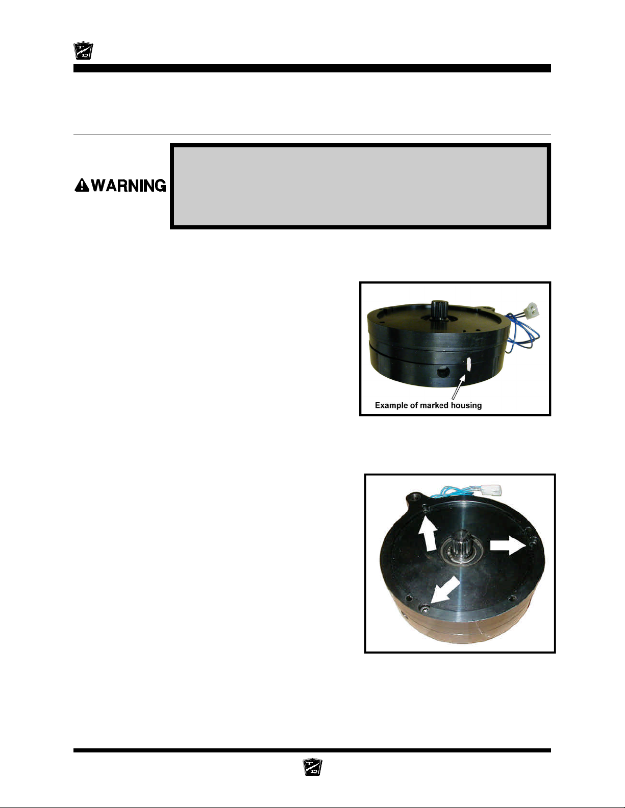
Maintenance, Service, and Repair
REPLACE THE PARKING BRAKE LINING
(ELECTRIC MOTOR BRAKE)
Current Taylor-Dunn® brakes are asbestos free. However, there is the
possibility that the original brakes were replaced with aftermarket
parts containing asbestos. Since this possibility exists, all brake parts
should be handled as if they contain asbestos. Refer to appendix C for
recommended handling precautions.
1. Remove the electric brake assembly from the drive. Refer to Motor Removal and Installation
in the Transmission section for information regarding removing the brake.
2. Place the brake assembly on flat surface with the shaft pointing up.
3. Mark the orientation of the outer housing and
magnet. This mark will be used to correctly align
the housing during reassembly
4. Remove the three Allen head socket screws evenly
so that the internal spring pressure is reduced
gradually. Turn each screw no more than two turns
at a time.
5. Remove the outer housing and friction plate.
Brakes Page 12
Page 89
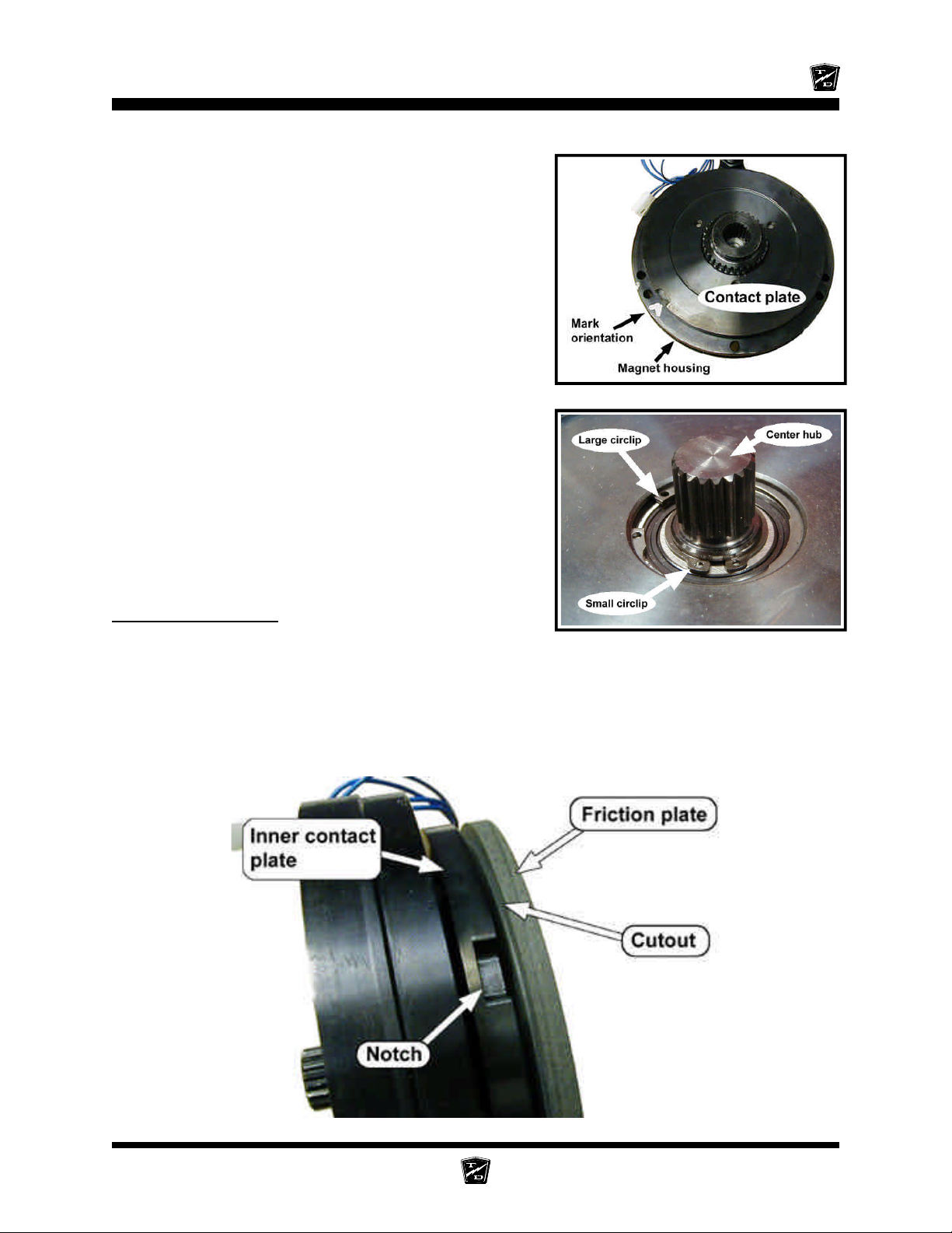
Maintenance, Service, and Repair
6. Mark the orientation of the inner contact plate in
relation to the magnet.
7. Remove the smaller bearing circlip.
8. Using a soft hammer, drive out the center hub and
remove the inner contact plate and six springs.
9. If required, remove the larger bearing circlip and
press out the bearing. If the bearing is removed it
must be replaced.
10. Thoroughly clean all parts.
11. Inspect all parts for damage or wear.
12. Reassemble in reverse order.
Reassembly Notes
a. Orientate the inner contact plate lining up the marks made when removed and so that the notches
face away from the magnet (see illustration below).
b. Orientate the friction plate so that the cutout faces the inner contact plate.
c. Orientate the outer housing lining up the marks made when it was removed.
d. Tighten the three Allen head socket screws in a cross pattern evenly so that the internal spring
pressure is increased gradually. Turn each screw no more than two turns at a time. Final torque10 ft-lbs.
Brakes Page 13
Page 90
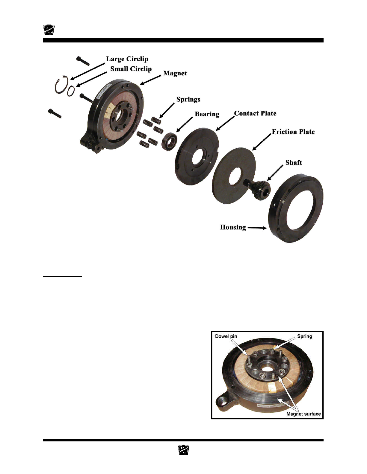
Maintenance, Service, and Repair
Inspection:
1. Measure the free length of the five springs. Minimum length =0.713”
2. Inspect the splines on the hub and the friction plate for damage.
3. Inspect the inner contact plate and the outer housing where they come into contact with the
friction plate for wear or damage.
4. Inspect the three dowel pins and their corresponding
holes in the inner contact plate. The dowel pins
should be straight and the holes should be round.
5. Inspect the bearing for excessive play or roughness
when rotated.
6. Inspect the contact surfaces of the magnet and inner
contact plate for damage and flatness.
Electric motor brake exploded
Note: There are no repairable parts in this assembly. The parts must be
replaced if any damage or wear is found.
Brakes Page 14
Page 91
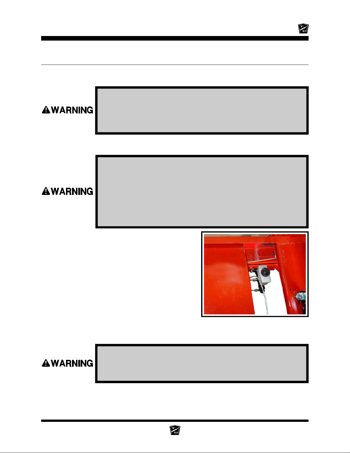
Maintenance, Service, and Repair
REPLACE FRONT DISC BRAKE PADS
NOTE: It is recommended that both the left and right brake pads be replaced
as a set.
Current Taylor-Dunn® brakes are asbestos free. However, there is the
possibility that the original brakes were replaced with aftermarket
parts containing asbestos. Since this possibility exists, all brake parts
should be handled as if they contain asbestos. Refer to appendix C
for recommended handling precautions.
NOTE: Installing new brake pads will raise the brake fluid level in the master
cylinder.
1. Make sure the key-switch is in the “OFF” position, then remove the
key.
2. Place the forward-reverse switch in the center “OFF” position.
3. Set the park brake.
4. Place blocks under the rear wheels to prevent vehicle movement.
5. Disconnect the main positive and negative cables at the batteries.
6. Thoroughly clean the area around the master
cylinder cap.
7. Remove fluid from the master cylinder until it is 1/2
full.
Master cylinder is located between the front
8. Raise the front of the vehicle and support with jack stands.
Always use a lifting strap, hoist, and jack stands, of adequate capacity
to lift and support the vehicle. Failure to use lifting and support devices
of rated load capacity may result in severe bodily injury.
seats. Dual reservoir shown.
9. Remove the tire/wheel assembly. Refer to Tires and Wheels section for information on removing
the tire and wheel assembly.
Brakes Page 15
Page 92
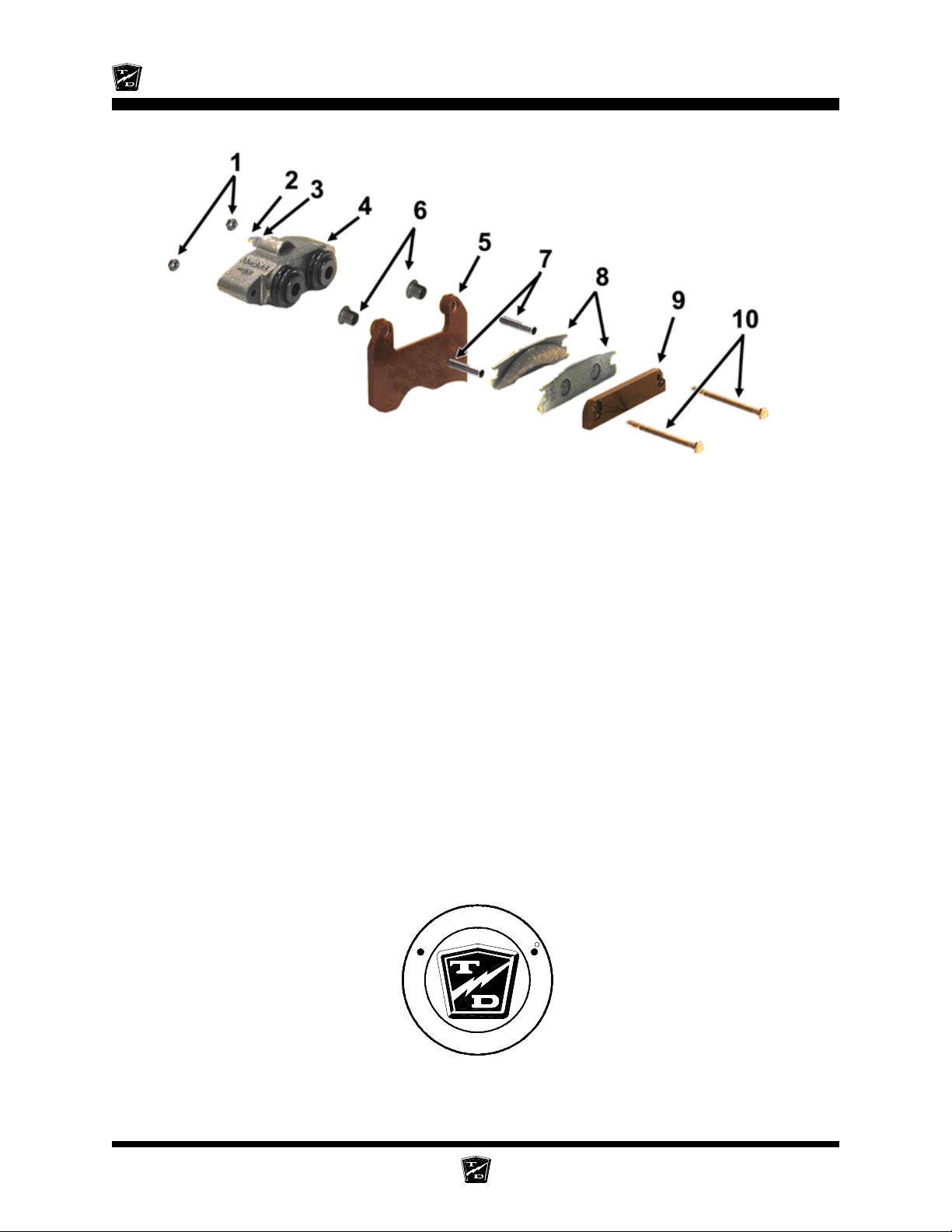
Maintenance, Service, and Repair
NOTE: Refer to the illustration above for the following steps.
10. Remove the brake body bolts (10) and discard the lock nuts (1) and brake pads (8).
11. Remove the spacer bushings (6) from the mounting bracket (5) and discard the bushings.
12. Inspect the brake rotor. See Inspect the Service Brakes section for information regarding
inspecting the brake rotor.
13. Inspect the spacers (7) and replace if any wear or damage is found.
14. Install new spacer bushings in the mounting bracket.
15. Install new brake pads in reverse order. Torque the mounting bolts to 11 ft-lbs.
16. Repeat this procedure for the other wheel.
17. Install the tire/wheel assembly and lower the vehicle to the ground.
18. Fill the master cylinder to the proper level. Refer to Check Master Cylinder Fluid section
for information on the proper master cylinder fluid level.
19. Reconnect the main positive and negative cables at the batteries.
20. Remove the blocks from behind the wheels.
21. Release the park brake and test drive the vehicle.
-
R
D
O
L
Y
A
T
T
h
e
B
e
s
t
W
a
y
T
o
U
N
N
o
Y
G
t
u
o
o
b
A
Brakes Page 16
R
s
s
e
n
i
s
u
B
r
u
Page 93
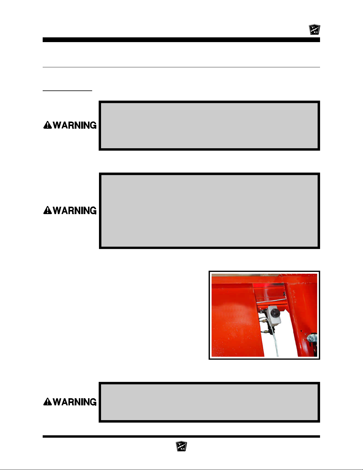
Maintenance, Service, and Repair
REPLACE REAR BRAKE PADS
Hydraulic Disc
Current Taylor-Dunn® brakes are asbestos free. However, there is the
possibility that the original brakes were replaced with aftermarket
parts containing asbestos. Since this possibility exists, all brake parts
should be handled as if they contain asbestos. Refer to appendix C
for recommended handling precautions.
NOTE: It is recommended that both the left and right brake pads be replaced
as a set.
1. Make sure the key-switch is in the “OFF” position, then remove the
key.
2. Place the forward-reverse switch in the center “OFF” position.
3. Set the park brake.
4. Place blocks under the front wheels to prevent vehicle movement.
5. Disconnect the main positive and negative cables at the batteries.
NOTE: Installing new brake pads will raise the brake fluid level in the master
cylinder.
6. Thoroughly clean the area around the master
cylinder cap.
7. Remove fluid from the master cylinder until it is
1/2 full.
8. Raise the rear of the vehicle and support with jack
stands.
Master cylinder is located between the front
seats. Dual reservoir shown.
Always use a lifting strap, hoist, and jack stands, of adequate capacity
to lift and support the vehicle. Failure to use lifting and support devices
of rated load capacity may result in severe bodily injury.
Brakes Page 17
Page 94
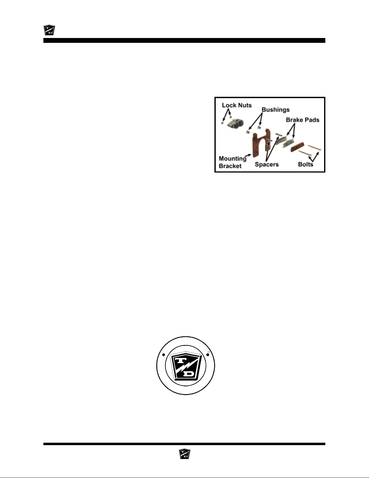
Maintenance, Service, and Repair
9. Remove the tire/wheel assembly.
NOTE: Refer to Tires and Wheels section for information on removing
the tire and wheel assembly.
10. Release the park brake (wheel brake only).
11. Remove the brake body bolts and discard the lock nuts and brake pads.
12. Remove the spacer bushings from the mounting
bracket and discard.
13. Inspect the brake rotor. Refer to Inspect the
Service Brake section for information regarding
inspecting the brake rotor.
14. Inspect the spacers and replace if any wear or
damage is found.
15. Install new spacer bushings in the mounting bracket.
16. Back off the parking brake adjustment (wheel park
brake only).
17. Install new brake pads in reverse order. Torque the
mounting bolts to 11 ft-lbs.
18. Repeat this procedure for the other wheel.
19. Install the tire/wheel assembly and lower the vehicle to the ground.
20. Fill the master cylinder to the proper level. Refer to Check Master Cylinder Fluid section
for information regarding the correct master cylinder fluid level.
21. Adjust the parking brake (wheel park brake only). Refer to Adjust the Parking Brake section.
22. Set the park brake.
23. Reconnect the main positive and negative cables at the batteries.
24. Remove the blocks from behind the wheels.
25. Release the park brake and test drive the vehicle.
-
R
D
O
L
Y
A
T
T
h
e
B
e
s
t
W
a
y
T
o
U
N
N
o
Y
G
t
u
o
o
b
A
Brakes Page 18
R
s
s
e
n
i
s
u
B
r
u
Page 95
Maintenance, Service, and Repair
REPLACE THE WHEEL CYLINDER
Disc Brake Body Assembly (front or rear)
Current Taylor-Dunn® brakes are asbestos free. However, there is the
possibility that the original brakes were replaced with aftermarket
parts containing asbestos. Since this possibility exists, all brake parts
should be handled as if they contain asbestos. Refer to appendix C for
recommended handling precautions.
Do not ingest brake fluid or allow contact with skin or eyes. Always
wear protective clothing and a face shield when working with or
around brake fluid.
SKIN CONTACT
Flush area immediately with water for several minutes. If a rash or
skin irritation develops, get medical attention immediately.
EYE CONTACT
Immediately flush the eye with water for 15 minutes and call
physician.
INGESTION
Get medical attention immediately.
1. Make sure the key-switch is in the “OFF” position, then remove the
key.
2. Place the forward-reverse switch in the center “OFF” position.
3. Set the park brake.
4. Place blocks under the wheels to prevent vehicle movement.
5. Disconnect the main positive and negative cables at the batteries.
6. Release the park brake.
7. Raise the wheel off of the ground and support with jack stands.
Always use a lifting strap, hoist, and jack stands, of adequate capacity
to lift and support the vehicle. Failure to use lifting and support devices
of rated load capacity may result in severe bodily injury.
Brakes Page 19
Page 96
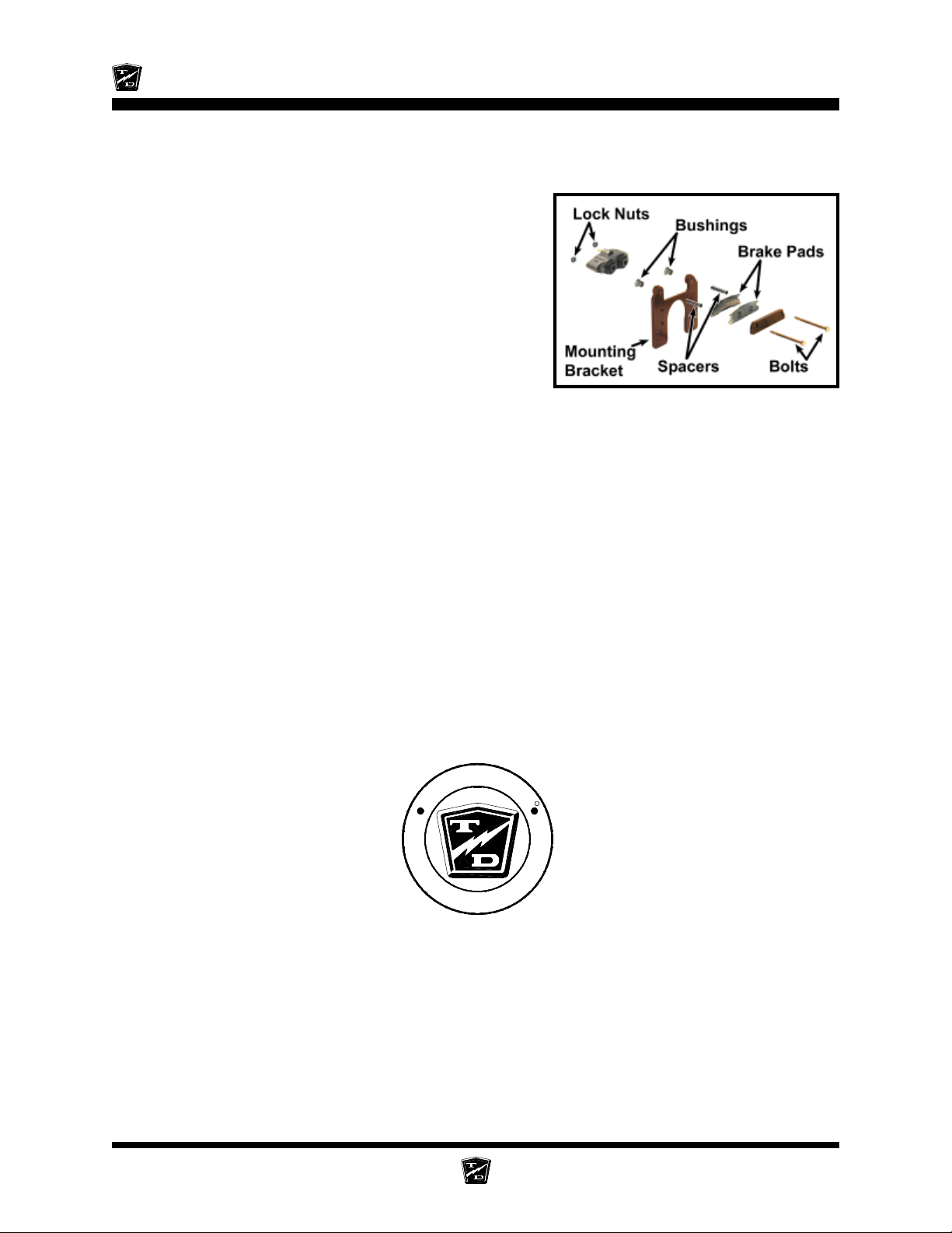
Maintenance, Service, and Repair
8. Remove the tire/wheel assembly. Refer to Tires and Wheels section for information on
removing the tire and wheel assembly.
9. Thoroughly clean the area around the brake body.
10. Remove the brake body bolts and discard the lock
nuts.
11. Inspect the brake rotor. Refer to Inspect the
Service Brake section for information regarding
inspecting the brake rotor.
12. Disconnect the brake hose from the brake body.
13. Install the new brake body assembly in reverse order.
• Use teflon tape thread sealant on the brake hose
fitting.
• Torque the brake body bolts to 11 ft-lbs.
14. Bleed the brakes. Refer to Bleed the Brakes section for information regarding bleeding the
brakes.
15. Set the park brake.
16. Reconnect the main positive and negative cables at the batteries.
17. Lower the wheel to the ground.
18. Remove the blocks from behind the wheels.
19. Release the park brake and test drive the vehicle.
-
R
D
O
L
Y
A
T
T
h
e
B
e
s
t
W
a
y
T
o
U
N
N
o
Y
G
t
u
o
o
b
A
Brakes Page 20
R
s
s
e
n
i
s
u
B
r
u
Page 97
Maintenance, Service, and Repair
REPAIR THE BRAKE BODY
Hydraulic brake system components must be kept clean. Make sure
your work area is free from dirt and debris and will contain any brake
fluid spills. Any debris or contaminates left in the brake system could
lead to brake failure and result in property damage and/or severe
bodily injury.
Do not ingest brake fluid or allow contact with skin or eyes. Always
wear protective clothing and a face shield when working with or
around brake fluid.
SKIN CONTACT
Flush area immediately with water for several minutes. If a rash or
skin irritation develops, get medical attention immediately.
EYE CONTACT
Immediately flush the eye with water for 15 minutes and call
physician.
INGESTION
Get medical attention immediately.
1. Make sure the key-switch is in the “OFF” position, then remove the
key.
2. Place the forward-reverse switch in the center “OFF” position.
3. Set the park brake.
4. Place blocks under the front wheels to prevent vehicle movement.
5. Disconnect the main positive and negative cables at the batteries.
6. Remove the brake body from the vehicle.
NOTE: Refer to Replace the Brake Body Assembly (front or rear)
section for information on removing the brake body.
7. Pull the pistons out of the brake body.
The pistons are very fragile. If the piston is damaged it must be
replaced. Failure to replace a damaged piston could lead to brake
failure and result in property damage and/or severe bodily injury.
8. Remove the piston rubber boot.
9. Remove the piston o-ring from inside of the brake body.
10. Inspect and replace parts as required.
Brakes Page 21
Page 98
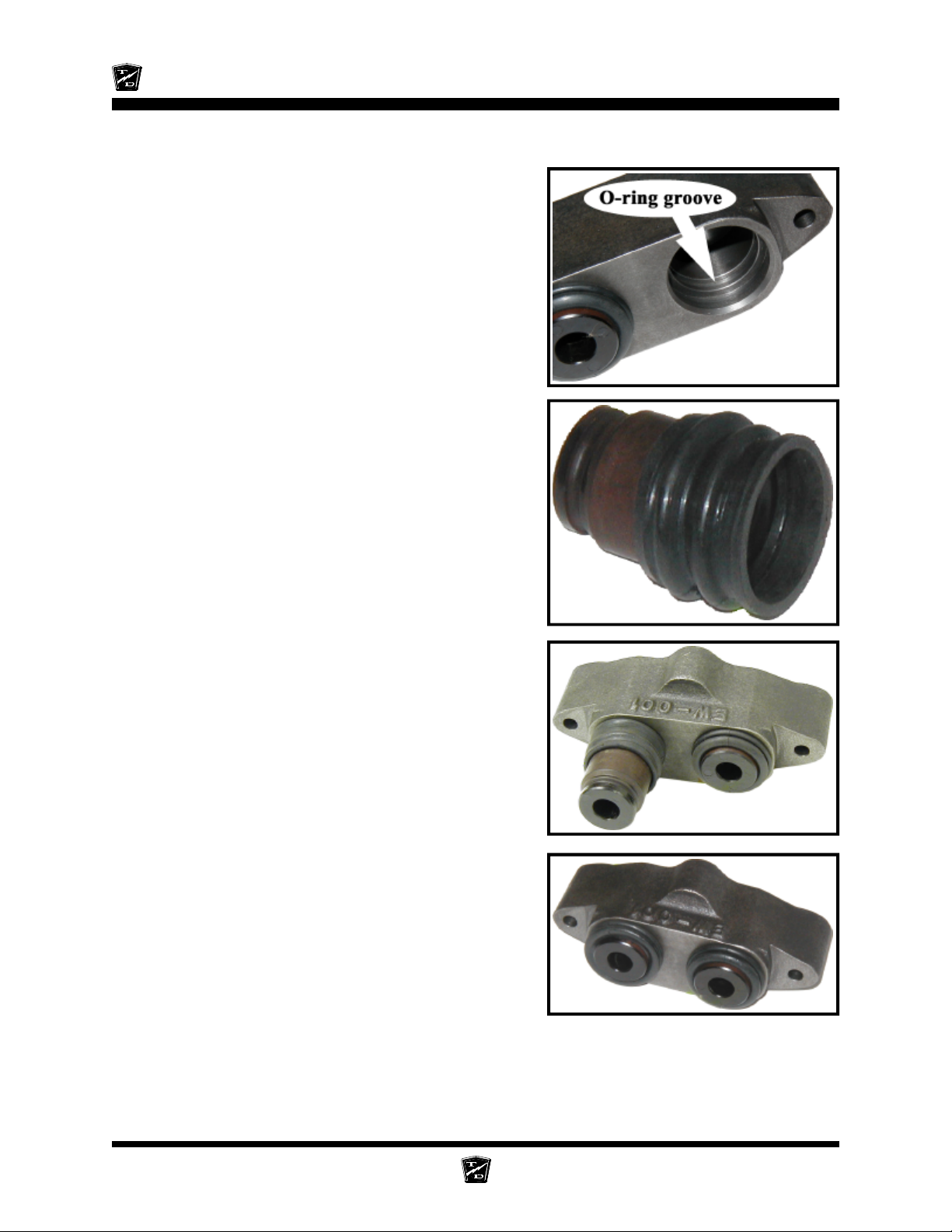
Maintenance, Service, and Repair
11. Lubricate the brake parts with clean brake fluid from a sealed container.
12. Install the o-rings into the brake body. Make sure
that the o-rings are installed into the second groove
and that they are not twisted.
NOTE: There are two different brake assemblies. One has a
standard o-ring with a round cross section, the other
has a square cross section. The two o-rings are not
interchangeable. The square o-ring is not available as
a replacement part. If the square o-ring is damaged,
the entire brake assembly must be replaced.
13. Using tool #41-350-13, slide the rubber boots onto
the pistons as shown. The boot should be hanging
off of the end of the piston.
14. Insert the rubber boot/piston into the brake body
making sure that the boot is properly seated in the
groove.
15. Press the pistons all the way down into the brake
body making sure that the boot seats properly into
the upper groove on the piston.
16. Install any fittings or plugs that were removed from
the brake body using teflon tape thread sealant.
17. If the brake body assembly is not to be immediately
installed onto a vehicle, plug the brake hose fitting
hole to prevent any contaminates from entering the
brake body.
Brakes Page 22
Page 99
Maintenance, Service, and Repair
REPLACE THE MASTER CYLINDER
Do not ingest brake fluid or allow contact with skin or eyes. Always
wear protective clothing and a face shield when working with or
around brake fluid.
SKIN CONTACT
Flush area immediately with water for several minutes. If a rash or
skin irritation develops, get medical attention immediately.
EYE CONTACT
Immediately flush the eye with water for 15 minutes and call
physician.
INGESTION
Get medical attention immediately.
1. Make sure the key-switch is in the “OFF” position, then remove the
key.
2. Place the forward-reverse switch in the center “OFF” position.
3. Set the park brake.
4. Place blocks under the rear wheels to prevent vehicle movement.
5. Disconnect the main positive and negative cables at the batteries.
NOTE: Most vehicle configurations do not require lifting the vehicle to
remove the master cylinder. Lifting the vehicle may not be required.
6. If required, raise the vehicle and support with jack stands.
Always use a lifting strap, hoist, and jack stands, of adequate capacity
to lift and support the vehicle. Failure to use lifting and support devices
of rated load capacity may result in severe bodily injury.
7. Place a drain pan under the master cylinder.
8. Disconnect the brake line(s) to the master cylinder and pump out the fluid in the master cylinder
by depressing the pedal several times.
9. Remove the master cylinder bolts and remove the master cylinder from the vehicle.
Brakes Page 23
Page 100
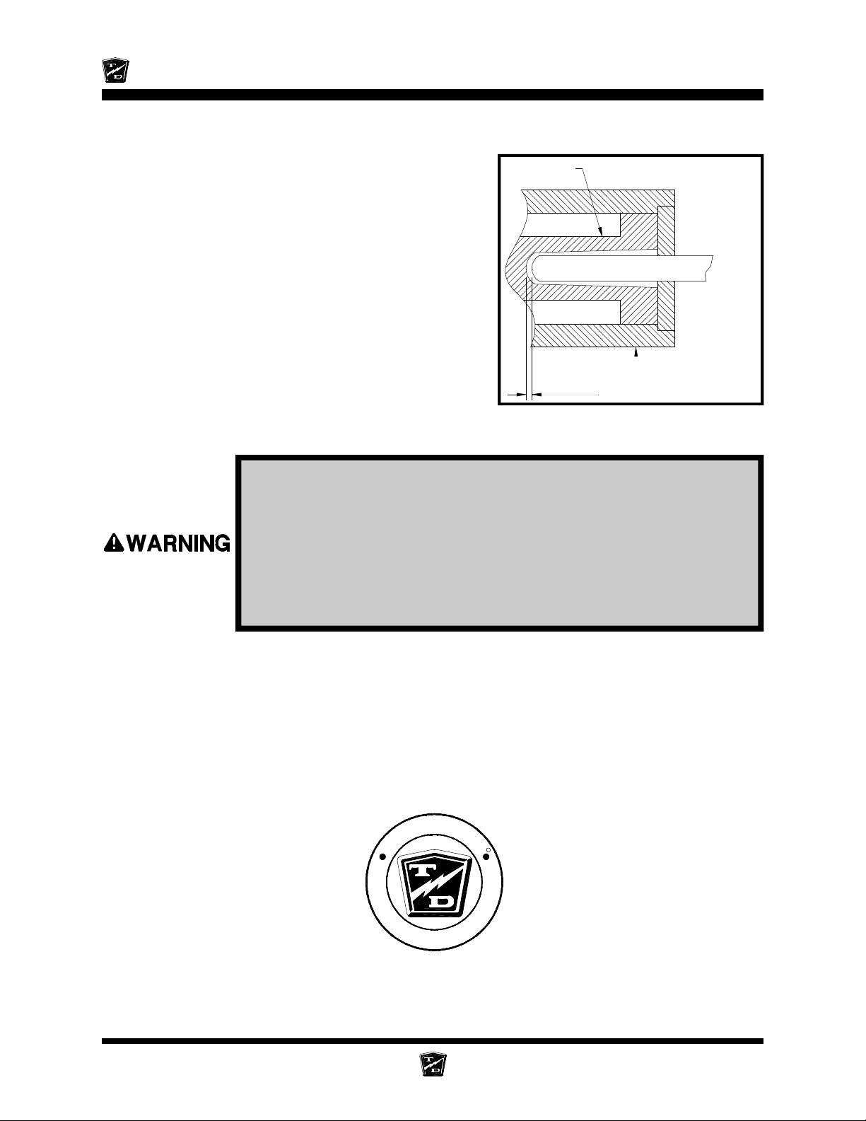
Maintenance, Service, and Repair
1/8"
10. Install in reverse order.
11. Adjust the master cylinder push rod so that it is
approximately 1/8 inch away from the master
cylinder plunger when the brake pedal is up.
12. Fill the master cylinder with brake fluid from a sealed
container.
13. Pump the brake pedal a short distance of one to
two inches until no bubbles are seen coming from
the inlet ports inside of the master cylinder chamber.
14. If the vehicle was raised, lower it to the ground.
15. Bleed the brakes. refer to Bleed the Brakes section
for information regarding bleeding the brakes.
16. Reconnect the main positive and negative cables
at the batteries.
17. Remove the blocks from behind the wheels.
18. Release the park brake and test drive the vehicle.
Plunger
Push Rod
Master Cylinder
Cutaway of typical master cylinder showing
the push rod clearance
• Only use DOT 3 brake fluid from a new sealed container.
• DOT 3 brake fluid is corrosive and will damage paint finishes.
• Dispose of brake fluid in accordance with local state and federal
regulations.
• Read and follow all warnings on the brake fluid container.
-
R
D
O
L
Y
A
T
T
h
e
B
e
s
t
W
a
y
T
o
U
N
N
R
s
s
e
n
i
s
u
B
r
u
o
Y
G
t
u
o
o
b
A
Brakes Page 24
 Loading...