

Taxan Super Vision IVm, Super Vision IV, Super Vision 630, Super Vision 640 Service Manual
,.
.'~
.
:'.:',
- I •
:-,
\",,':'-;-.:''''!
\.,
-:
, '
••
,":"
':
':
c,
.:
• '
:."
••
, : <
. ." .
.•
'
,"",
, " .
..
:"'<;/<':;,C;"
SERVICE
"MANUAL
.
. \
.'
.
r
i,
.
. I
I
..
i .
.1
.
12"
'.
COLOR DISPLAY'
SUPER
VISION
DOtlI
DrYl~M
.
, ' . '. , . . TM
-SUPER
VISION
fbJ3JillJlflnlJ{][I1J
, .
IMPORTANT
SERVICE
SAFETY
;
Operatic.n,of monitor outside
of
cabinet
or
with back removed
involves a shock hazard. Work
on
these models should only
be
performed
by
those who arll thoroughly familiar. with prccau-
..
tions neCessary when working on high voltage equipment
•.
Exercise care
when
servicing this chassis with power applied.
Many 8 plus and high voltage
RF
terminals are exposed which.
if
carelessly contactlld. can cause serious shock
or
result
in
dam-
age
to
the
chassis. Maintain interconnecting ground lead con-
. ncetions
bet.ween
chassis. escutcheon and picture tube dag cluster
when operating chassis. The
+8
Adj.Control in this monitor is
sealed
in
order
to.protect
the user from X-ray irradiation. The
...
'
B Adj.Control should
oot
normally have
to
be
adjusted.But
iC
it
is..cr
Ie
it
is replaced due to damage.check the +B voltage to as-
sure that.
it
is within specifications
after
adjustment.Then seal
this control according
to
the manuCacture's specification.
Certain H Y failures can increase X-ray radiation. Monitors
should
not
be
operated with H Y levels exceeding the
specified
rating
for
th«;
chassis
type. The maximwn operating H Y specified
for
the
chassis used
in
these
monitor
is
22
KV
at
zero beam current with a line voltage
of
120Y
AC.
Higher voltage may also increase possibility of failure
in
H·Ysupply.
It
is
important
to
maintain
specified values
of
aU
components'
in
the horizontal and high voltage circuits and anywhere else in
the
monitor
that
could cause a rise in high voltage
or
operating
supply voltage.No changes should
be
made
to
the original de-
sign
olthe
monitor. Components shown in the shaded areas od
the schematic diagram
and/or.
identified
by
&. *
in
the re-
placement.
parts
list should
be
replaced only with exact Factory
recommended replacement
parts.
The use
of
unauthorized
substitute
parts_ may create a shock.
fire.X- ray
radiation.or
other
hazard.
To determine the presenCe
of
high voltage. use an accurate.high
. impedance.H Ymeter connected between
the
second anode leitd
and the CRT dag
groundin~
device_When servicing the High
Yoltage System.remove
static
charge
e~om
it
by
connp.cting a
10K
ohms resistor in series with an insulated wire (such as a
test probe) between picture tube
dag
and 2nd anode lead.
(AC,
line cord disconnected
Crom
AC
supply.)
The picture tube. used in this·
monitor
employs integral implo-
sion protection. Replace with a tube
at the same type number
,Cor
continued
safety.Do
not
IiCt
picture tube by the neck.Han-
dIe
the picture tube only when wearing shatter-proof goggles
and
after
discharging the high voltage completely.Keep l)ttiers
withoutshafter-proofl goggles away.
When
removing springs
or
spring mounting
parts
from the
chassis.shatter-proof gottgles
must
be worn.Keep others without
shatter-proof
goggles away.
••••
e'
SAFETY INSPECTION • •
lor
e'
•
Before returning the monitor to
the
user. per
Corm
the following
safelY checks:
INFORMATION
Super Vision IV /IVM
Super Vision
640/630
• • •
...
PROTECT YOUR CUSTOMER • • • • •
Llnspect all lead dress
to
make certain
that
leads
are
not
pinched and
that
hardware
is
not lodged between the chassis
and, other metal
parts
in the monitor.
2.Replace all protective devices such
as
non·metaUic control
knobs.cabinet back.l\djustment covlu·s.shields.etc.
3.To
be
sure tllat no shock
hazarc!exists.a
check
for the pres·
enee
oC
leakage current should
be
made
at
eech exposed
metal'
part
having a return
path
to
the chassis(jack.cabinet metal.
screw heads. knobs.shaftli.etc.)in the following manner.
Plug the
AC
line cord directly into a 120Y
AC
receptacle.(Do
not use an Isolation Transformer during these checks. ) All
tP.Sts
must be repeated with' the
AC
Hne
cord plug connections.
l'e~
versed.
(If
necessary.a non-polarized
AC
adapter
plug must
be'
used for .the purpose
of
completing these checks.
Do
not other-
wise operate the monitor with an
adapt,.r.)
Ie
available.measure leakage current using an accurate leakage
current tester.Any reading oCO.35MA
or
more· is excessive and
indicates
II
potential shock hazard which must
be
corrected
be-
Core
returning the monitor
to
the owner.
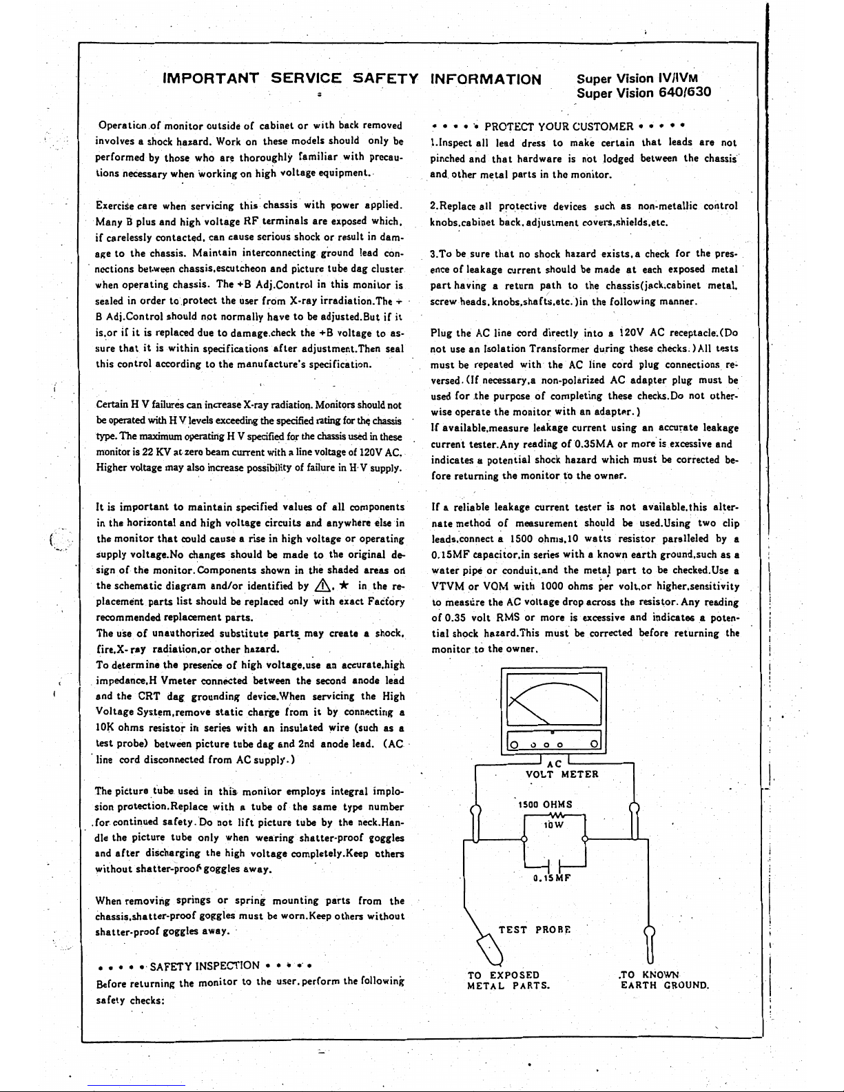
If
a reliable leakage current tester is not available. this alter-
nate method
of
meesurement
sho~I1d
be
used. Using two clip
leads. connect a 1500 ohm:l.l0
watts
resistor paralleled
by
a
0.15MFeapacitor.inseries
with a known
earth
ground.such as.a
water
pipe
or
conduit. and the meta}
part
to
be checked.
Use
a
VTYM
or
YOM with 1000 ohms per
volt.or
higher.sensitivity
to measlire the
AC
voltage drop across the resistor.
Any
reading
of
0.35 volt RMS
or
more is excessive and indicate&a
poten~
tial
shock hazard.This
must
be
corrected before returning the
monitor
to the own.er.
!
!
. ,
0)
a 0
_-----'ACL------,
VOLT
METER
\.
I
1500
OHMS
lOW
O.ISMF
TEST
PROBE
I
TO
EXPOSED
.TO KNOWN
METAL
PARTS_
EARTH
GROUND.
I
, .
IMPORTANT
NOTICE
FOR
SERVICE PERSONNEL BEFORE SERVIC'ING
PLEASE READ BEFORE ATTEMPTING SERVICE
1.' While
the
monitor
isin
operation, do
not
attempt
to
connect
or
disconnect any wires.
10',
sis
2. Make sure
the
power cord is,disconnected before replacing any components
in
the monitor.'
rol
3. When
the
power
is
on, do
not
attempt
to
short any portion
of
the circuit. This shorting may
cause damage
to
the
transistors
in
the monitor.
as·
lal
4.
When servicing
the
H;
V.
area,
be
certain tl:lat
the
C.
R~
T anode is.safely discharged
to
ground
Ill.
before removing
the
anode cap.
)0
5.
Caution, must be exercised
when
servicing this monitor.
;I.S
, The regulator has no current Iimitinganq even a momentary short
of
an
output
voltage could
~e-
cause destruction
of
the
pass transistors.
be
!r-
gt'
i
le-
I
,
I
tr
..
i
ip
I
I '
a
a
"'
i
,
a
ly
Ig
~-
Ie
/
....
- 1 -
IProduct. Outline
'I
This model
is
a 12-inch color display monitor,
used
for a personal computer terminal.
Its
input
is
TIL
s~parate
signals. The input terminal
is
an
8-pin
DIN
)ack.
Specifications
CAT
Signal
input
'
Power Supply
Wattage
Cabinet
Dimensions
Weight
Scanning
frequency
OPERATION
12-inch
type
with
646.8
mm R
• Facing: Non-glare' face 'plate
Facing: Glare face plate
• Screen phosphor:
630/640
Separate
R,
G,
B,
I,
H, V
•
R,
G,
B,
I:
."
Positive
• Sync: Positive or negative
Local commercial
power
supply
SOW
Plastic
630/640A,
B,
S
,
630/640U,
J
B22
(Short persfstence)
322
(W) x 309
(H) x 372
(D)
mm
.
12
kg
24.S
kHz (Horizontal)
54.3
Hz (Vertical)
1.
Plug
the display
and
the computer into
AC
outlets.
2. Set
the
color mode switch
on
the
rear
panel.
3. Connect the signal input terminal
sm
the
rear
panel
to
the computer using the optional cable.
4. Turn on display monitor
and
computer.
5.
The
green
power indicator (just
above
tbe power 'switch), lights, then the
CRT
·screenbrightens.
(There
may
be
9haracters displayed.)
6.
After the monitor warms up,
set
brightness
and
contrast if necessary.
7. Position of the image, image
area,
and
focus
are
preset at
the
factory,
so
you
don't have
to
adjust
these. Depending
oriyour
computer, image width, height,
and
position may differ from
the
stan-
dard settings',
In
such a
case,
reset
as
necessary (controls
are
on
the
rear panell.·
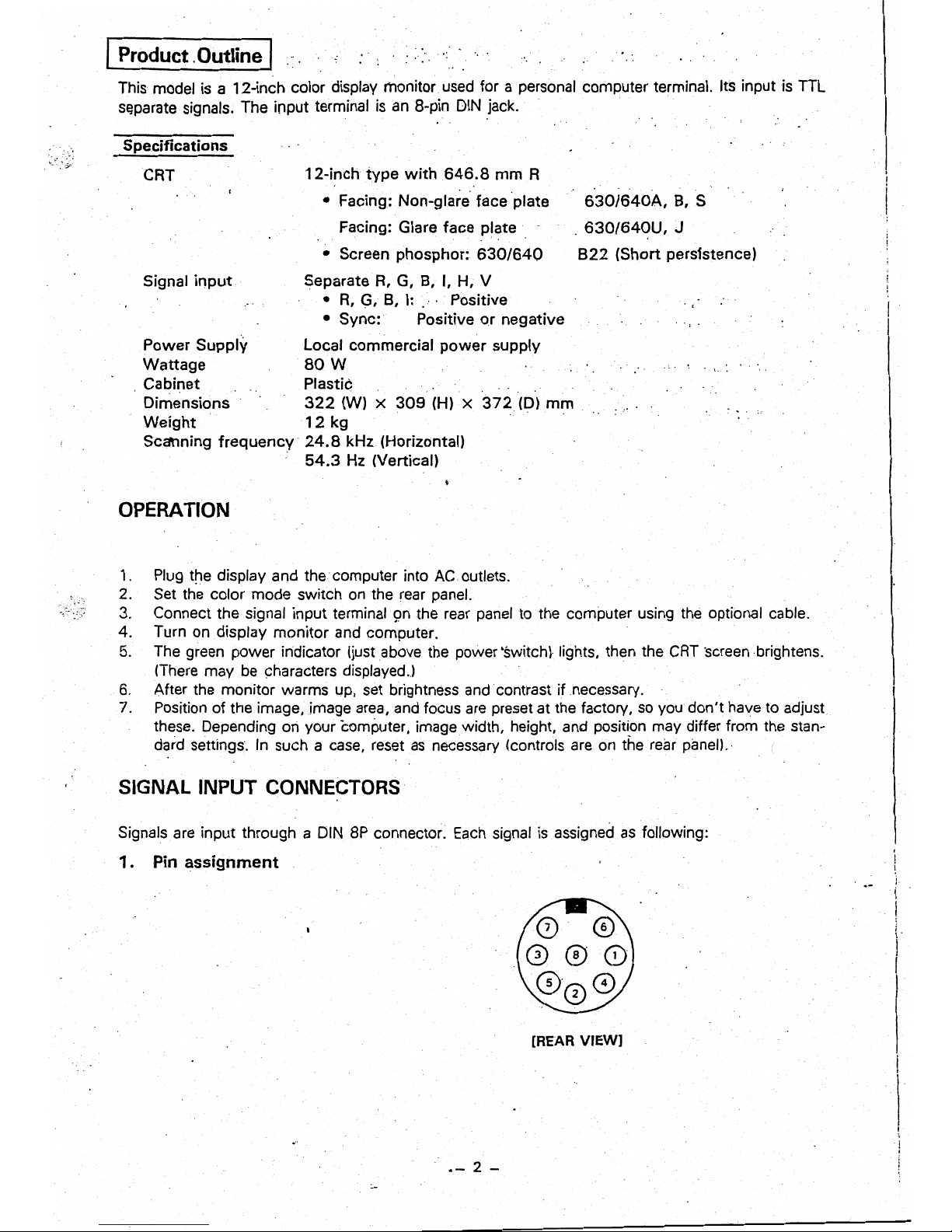
SIGNAL INPUT CONNECTORS
. .
Signals
are
input through a DIN
8P
connector.
Each
signal
is
assigned
as
following:
1 . Pin
assignment
[REAR
VIEW]
.-
2 -
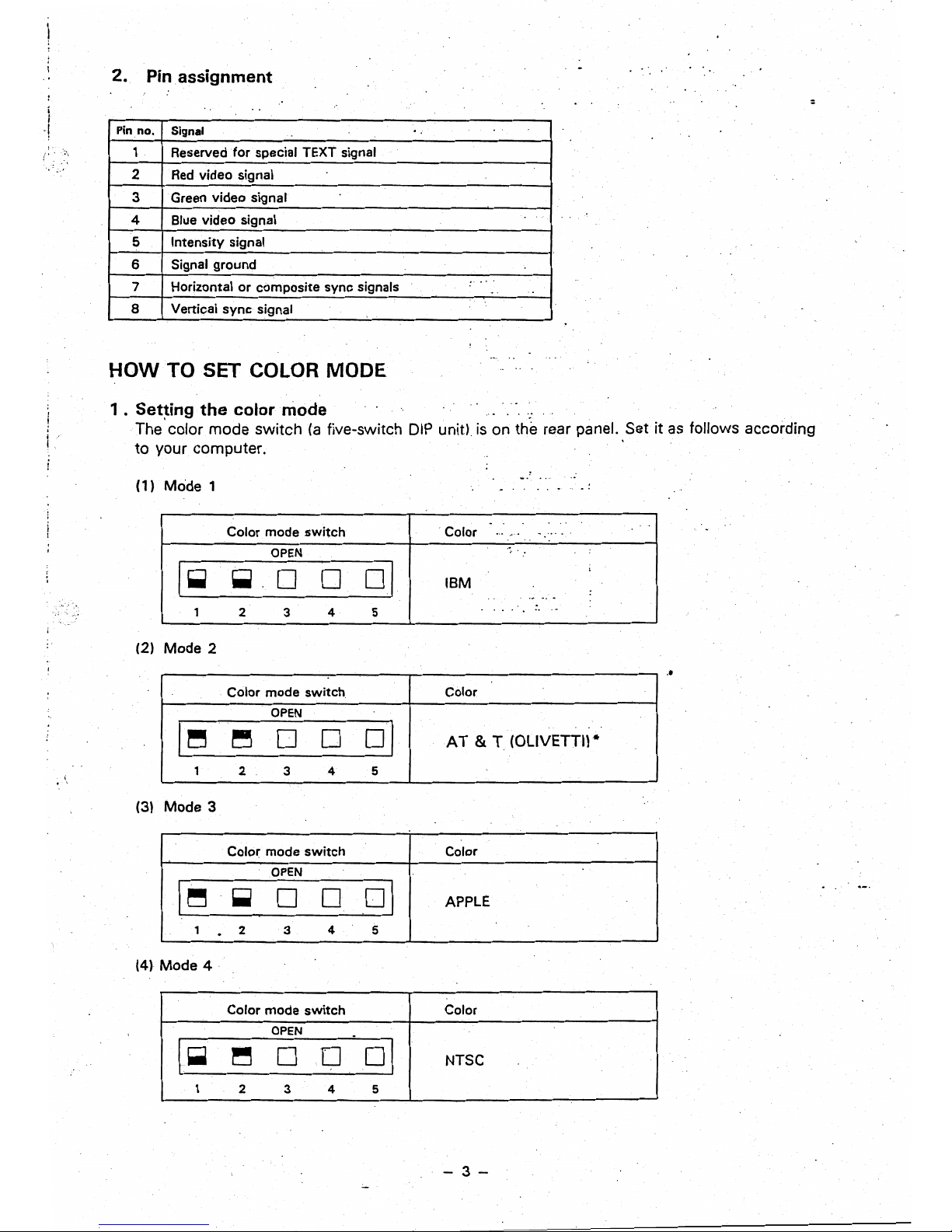
2.
Pin
assignment
:
i
.!
Pin
no.
Signal
1
Reserved
for
special TEXT signal
2
Red
video signal
3 Green video signal
4 Blue video signal
5
Intensity signal
6 Signal ground
.. .
7 Horizontal
or
composite sync signals
~.
..
8 Vertical
sync
signal
HOW
TO SET COLOR MODE
1 .
Set~ing
the
colarmade
.;
The
color mode switch
(a
five-switch
DIP
unit)
is
on the rear panel. Set it
as
follows according
to your computer.
(1) Mode 1
.
Color mode
switch
. Color
...
~'.
. .
..
' .
I-
OPEN
,
~
0 0
oj
IBM
:
.,.
~.
. .
..
..
1
2 3 4 5
(2) Mode 2
..
Color mode
switch
Color
OPEN
AT
& T (OLIVETTI) *
I~
~
0
0
01
1 2
3
4 5
(3) Mode 3
Color mode
switch
Color
I~
OPEN
01
~
0 0
APPLE
1
.
2
3
4
5
(4l
Mode
4·
Color mode
switch
Color
I-
OPEN
.
~
0 D
01
NTSC
1
2 3 4
5
-3-
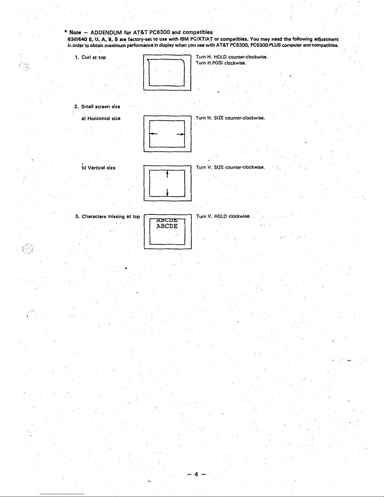
•
Note
- ADDENDUM
fgr
AT&T
PC6300
and compatibles
630/640
E,
U.
A,B.
S are factory-set to use
with
IBM PC/XT/AT
Of
compatibles. You may need the following adjustment
.in
order
to
obtain maximum performance in display when you use with AT&T PC6300. PC6300
PLUS
computer
and
compatibles.
,.
Curl at top
Turn H.
HOLD
counter-clockwise.
Turn
HoPOSI
clockwise .
D
. 2. Small screen size
al
Horizontal size
Turn
H.
SIZE
c;ounter-clockwise.
bl
Vertical size
Turn
V.
SIZE
counter-clockwise.
CJ
3. Characters missing
at
top
Turn
V.
HOLD
clockwise
..
-4-

2.
Setting
the
sync
signal input
mode
(fifth color
mode
switch)
The sync signal of nearly any personal computer can
be
inp~t
by turning off the fifth
DIP
switch.
But the sync signal
of
a few computers can be input only with this switch on. The following
table shows the switch setting
for
a number of sync signals.
Color mode switch Condition Signal type
OPEN
H. sync: Positive TTL level
A
V. sync: Negative TTL level
10
0
D 0
~I
H. sync: Negative TTL level
8
V. sync: Positive TTL level
1
2
3
4 5
.
C
H. V. sync composite, positive
OPEN
H. sync: Positive TTL level
a
V.sync:
Positive TTL level (AT&T)
10
0 0
0
~I
H. sync:
~egative
TTL level
b
V.
sync: Negative,TTL level (18M,
1 2 3
4
5
JAPANESE)
e'
c
H.
V.
sync
composite. ne'gative
3
'.
Setting
the
signal color display
mode
Turnin'g
of
the TEXT switch
(on
the
front
of the unit) changes the display
to
single-color mode.
Super Vision monitor can now be
used
as
a monochrome display monitor. There are four basic
monochrome modes: green, amber, reversed white,
and
white
on
blue.
The
monochrome mode
is
set by the third and fourth DIPswitches
as
follows.
, ' I
,
color
Color
mode
switch
OPEN, '
I
Green'
10
D
~
~
01
1
,2
3
4 5
r
10
0
OPEN
01
i
~.,
~-
Amber
3
4 5
I
-
1 2
\0
OPEN
01
l
~
,
••
Reversed
white
0
~
~
1
2
3
4
5
OPEN
*.
White
on
blue
10
0
~
~
01
1 2
3
4-
5
-
-Note:
In reversed white or white on blue Uppermost raster does nofappear
/'
mode,
the
following phenomena
or its disappearing position varies
may appear
as
described
on
the 'depending on the brightness,
right.
These are quite normal for this
One
or both
ends
are
brighter
V
mode.
v
than other
areas
.
......
lowest
two or three rasters run
off
the screen.
- 5 -
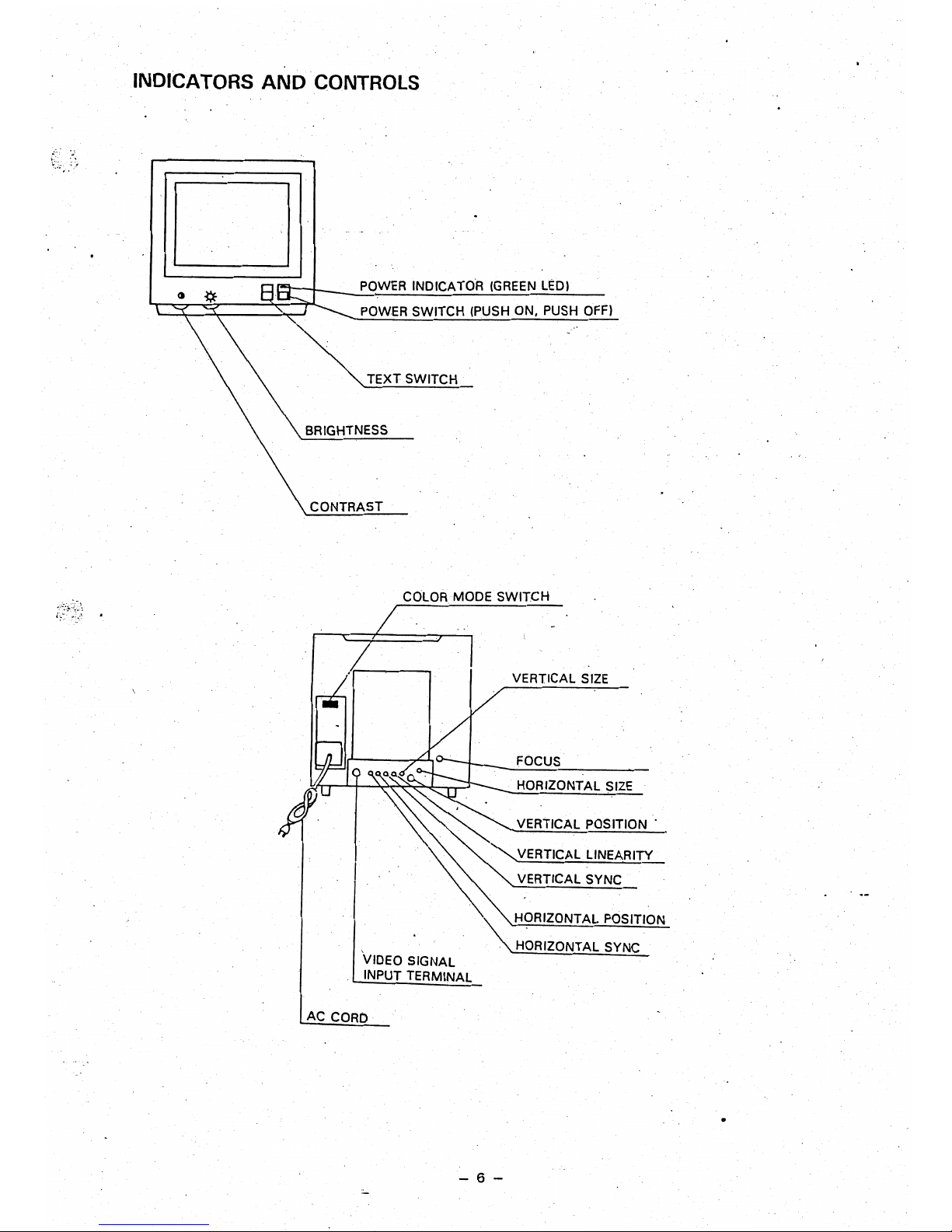
INDICATORS·
AND
CONTROLS
POWER
INDICATOR
(GREEN
LEDI
POWER
SWITCH (PUSH ON. PUSH
OFF)
TEXT SWITCH
BRIGHTNESS
CONTRAST
COLOR
MODE SWITCH
VERTICAL
SIZE
FOCUS
. HORIZONTAL
SIZE
VERTICAL
POSITION·
~
'"
""'VERTICAL
LINEARITY
•
'\:
VERTICAL SYNC
.•
'.'
~ORIZONTAL
POSITION
. '"HORIZONTAL SYNC
VIDEO SIGNAL
INPUT TERMINAL
AC
CORO
- 6 -

(
..
I
I
.
I
ADJUSTING THE DISPLAY
;
1. H. SIZE
If the horizontal size
of
the screen image
is
too short or too long. adjust the
H.
SIZE
control for
the correct
size.
(See illustration
1.)
2.
V.
SIZE
If the vertical
size
of
the screen image
is
too short or too long, adjust
theY.
SIZE
control for the
correct size.
(See
illustration
2.1
.'
3. H.
POSt
If the screen image shifts horizontally. adjust the H.
pas!.
control for a correct image.
(See
illustra-
tion
3.)
.
4.
V.
POSI.
·If the
scree~image
shifts vertically, adjust the
V.
POSI.
control for a correct image.
(See
illustration
3.1
5. H. HOLD
If the screen image has horizontal stripes or if
the.
image moves left or right, adjust the
H.
HOLD
control for a clear stable image.
(See
illustration
4.1
6,
V.
HOLD ,
If the screen image moves or overlaps vertically, adjust the V. HOLD control for
astable
image.
(See
illustration
4,1
7.
FOCUS
Adjust the focus· for the sharpest image.
(See
illustration
6.1
8. V. LIN.
Adjust the
y.LlN
control so
the
height of characters
is
even over the whole screen.
(See
illustration
7.1
9.
CONTRAST
Turning
the.
CONTRAST control clockwise increases the contrast, turning it counterclockwise
. decreases the contrast.
10.
BRIGHT
Turni'ng the
iRIGHT
control clockWise
makes
the screen brighter, turning it counterclockwise makes
it darker.
11.
SUB-CONTRAST
To adjust the subcontrast, display a screen of characters then turn the
BRIGHT
control to the
clic~
stop position, and the CONTRAST control fully clockwise.
Now
adjust the SUB-CONTRAST control
(VR
140) to the position just before the characters ·become saturated
..
12.
H. CENTER
To adjust horizontal centering turn the
BRIGHT
and the CONTRAST controls fully clockwise with
nothing displayed on the screen. Then adjust the
H.
CENTER
VR
(R742) so that the raster
is
centered
on the screen.
-
7-
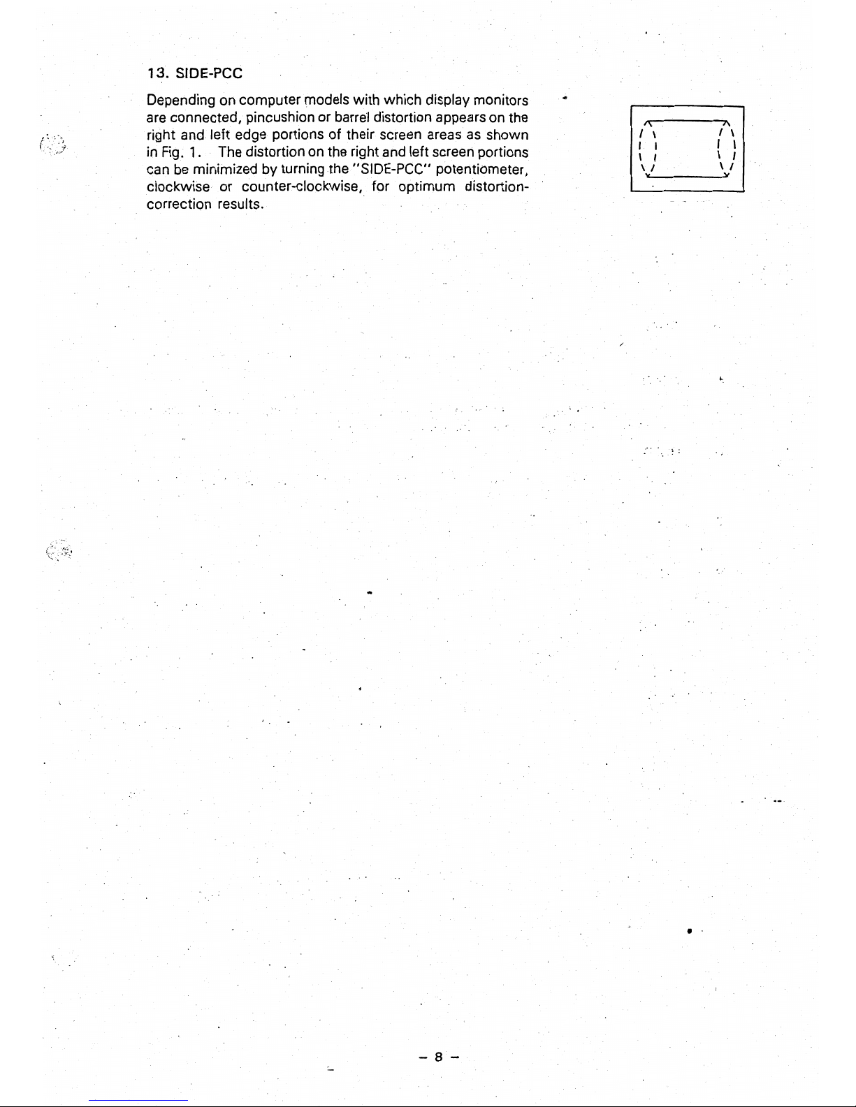
13.
SIDE-pee
Depending on computer models with which display monitors
are connected, pincushion or
barre'!
distortion appears on the
right and left edge portions of their screen areas
as
shown
in
Fig. 1..
The distortion
on
the right and left screen portions
can
be
minimized by turning the "SIDE-PCC" potentiometer,
clockwise or counter-clockwise, for optimum distortioncorrection results.
1\
J\
I \
I \
I ,
r
I
I I
\ I
\ I
\ I
"
"
:-. . .
~
•
- 8 -
 Loading...