

TAXAN PS-232Xh, PS-232X User Manual
DATA PROJECTOR
User’s Manual
KG-PS232Xh/232X
KG-PV131X/131S
IMPORTANT
DLP® (Digital Light Processing) and DLP® chip are registered trademarks of Texas Instruments Incorporated (U.S.A.).
•
VGA and XGA are trademarks or registered trademarks of International Business Machines Corporation (U.S.A.).
•
S-VGA is a registered trademark of Video Electronics Standards Association.
•
Microsoft, Windows, and PowerPoint are registered trademarks of Microsoft Corporation (U.S.A. and other countries).
•
Macintosh is a trademark of Apple Computer Inc. (U.S.A.).
•
Note that even in the absence of explanatory notes, serious attention is paid to the trademarks of the various companies
and to the product trademarks.

Important safety information
This device complies with Part 15 of the FCC Rules. Operation is subject to the following two conditions. (1) This device may
not cause harmful interference, and (2) this device must accept any interference received, including interference that may
cause undesired operation.
Type of Product:
Equipment Classification:
Models:
Projector
Class B Peripheral
KG-PV131S, KG-PV131X, KG-PS232X, KG-PS232Xh
U.S. Responsible Party:
Address:
Tel. No.:
PLUS Vision Corp. of America
9610 SW Sunshine Court Suite 500 Beaverton,
OR 97005
(503) 748 8700
We hereby declare that the equipment specified above
conforms to the technical standards as specified in the FCC Rules.
DECLARATION OF CONFORMITY
Precautions
Thank you for your purchase of this TAXAN data projector.
Please read this User’s Manual to the end so that you will be able to use this product properly.
After reading, keep this manual together with the Warranty in a safe place so that you may refer to it whenever you need it.
Please read this User’s Manual should there be something that you need to know during operation of the projector or in case
of an irregularity.
This User’s Manual covers models KG-PS232Xh/KG-PS232X, and KG-PV131X/KG-PV131S.
The projection distance is the same in these models, but the screen resolution, auto focus function, and some other functions
are dierent.
See the table below and the “Major Specications” for details. See Pages E-90 to 93.
Model Resolution (Full Function) Auto Focus Function
KG-PS232Xh 1024 × 768 (XGA)
KG-PS232X 1024 × 768 (XGA)
KG-PV131X 1024 × 768 (XGA) —
KG-PV131S 800 × 600 (S-VGA) —
○: Function included, —: Function not included
○
○
E-2
Data Projector
Important safety information
CAUTION
TO PREVENT SHOCK, DO NOT OPEN THE CABINET. NO USER-SERVICEABLE PARTS INSIDE. REFER SERVICING TO QUALIFIED
KAGA COMPONENTS SERVICE PERSONNEL.
This symbol warns the user that uninsulated voltage within the unit may have sucient magnitude to cause
electric shock. Therefore, it is dangerous to make any kind of contact with any part inside of this unit.
This symbol alerts the user that important literature concerning the operation and maintenance of this unit has
been included. Therefore, it should be read carefully in order to avoid any problems.
The above cautions are given on the bottom of the product.
WARNING
TO PREVENT FIRE OR SHOCK, DO NOT EXPOSE THIS UNIT TO RAIN OR MOISTURE. DO NOT USE THIS UNIT’S GROUNDED PLUG
WITH AN EXTENSION CORD OR IN AN OUTLET UNLESS ALL THREE PRONGS CAN BE FULLY INSERTED. DO NOT OPEN THE
CABINET. THERE ARE HIGH-VOLTAGE COMPONENTS INSIDE. ALL SERVICING MUST BE DONE BY QUALIFIED KAGA COMPONENTS SERVICE PERSONNEL.
RF Interference
WARNING
This equipment has been tested and found to comply with the limits for a Class B digital device, pursuant to Part 15 of the
FCC Rules. These limits are designed to provide reasonable protection against harmful interference in a residential installation. This equipment generates, uses and can radiate radio frequency energy and, if not installed and used in accordance
with the instructions, may cause harmful interference to radio communications. However, there is no guarantee that interference will not occur in a particular installation. If this equipment does cause harmful interference to radio or television
reception, which can be determined by turning the equipment o and on, the user is encouraged to try to correct the
interference by one or more of the following measures:
Reorientate or relocate the receiving antenna.
•
Increase the separation between the equipment and receiver.
•
Connect the equipment into an outlet on a circuit dierent from that to which the receiver is connected.
•
Consult the dealer or an experienced radio/TV technician for help.
•
DOC Compliance Notice
This Class B digital apparatus meets all requirements of the Canadian Interference-Causing Equipment Regulations.
Hg: Lamp in This Product Contains Mercury. Dispose of Lamp According to Local, State or Federal Law.
KG-PS232Xh/232 X | KG-PV131X/131S User’s Manual
E-3

Important safety information
Important Safeguards
These safety instructions are to ensure the long life of the unit and to prevent re and shock. Please read them carefully and
heed all warnings.
Installation
For best results, use the unit in a darkened room.
•
Place the unit on a at, level surface in a dry area away from dust and moisture.
•
Do not place the unit in direct sunlight, near heaters or heat radiating appliances.
•
Exposure to direct sunlight, smoke or steam can harm internal components.
•
Handle the unit carefully. Dropping or jarring can damage internal components.
•
Do not place heavy objects on top of the unit.
•
Power Supply
The unit is designed to operate on a power supply of 100 - 240 V 50/60 Hz AC. Ensure that your power supply ts these
•
requirements before attempting to use the unit.
Handle the power cable carefully and avoid excessive bending. A damaged cord can cause electric shock or re.
•
Disconnect the power cable (main’s lead) from the power outlet after using the unit.
•
Before disconnecting the power cable, make sure that the indicator of the POWER/STANDBY button lights in orange (not
ashing or in blue).
Cleaning
Disconnect the power cable (main’s lead) from the unit.
•
Clean the cabinet of the unit periodically with a damp cloth. If heavily soiled, use a mild detergent. Never use strong deter-
•
gents or solvents such as alcohol or thinner.
Use a blower or lens paper to clean the lens, and be careful not to scratch or mar the lens.
•
Clean the ventilation slots and speaker grills on the unit periodically using a vacuum cleaner. If accumulated dust blocks the
•
ventilation slots, the unit will overheat, which may cause the unit to malfunction.
Use a soft brush attachment when using the vacuum cleaner. Do not use a hard attachment, such as a crevice tool, to prevent the damage to the unit.
Lamp Replacement
Be sure to replace the lamp when the LAMP indicator comes on. If you continue to use the lamp after 2000 hours of usage,
•
the lamp will turn o.
Fire and Shock Precautions
Ensure that there is sucient ventilation and that vents are unobstructed to prevent the buildup of heat inside the unit. Al-
•
low at least 10 cm (4 inches) of space between the unit and walls.
Prevent foreign objects such as paper clips and bits of paper from falling into the unit. Do not attempt to retrieve any ob-
•
jects that fell into the unit. Do not insert any metal objects such as a wire or screwdriver into the unit. If something should
fall into the unit, immediately disconnect the power cable from the unit and have the object removed by a qualied KAGA
COMPONENTS service person.
Do not place any liquids on top of the unit.
•
Carrying around
When carrying the unit around, please use the soft case that comes with it and, to protect the lens from scratches, always shut
the lens shutter. Also, do not subject the unit to strong mechanical shock.
CAUTION – HOT!
The area around the exhaust vents is hot during and immediately after image projection.
To avoid burns, keep your hands away from this area.
Wait until the exhaust vents area cools o before touching it.
Do not look into the lens while the unit is on. Serious damage to your eyes could result.
E-4
Data Projector

Ways of Viewing this Manual
There are ve ways to search for information in this manual.
I just want to start using the projector
1
“The Procedure from Projection to Turning O the Power”
➜ See Page E-21
This introduces the basic operations of this product.
I would like to know about convenient functions when
2
projecting
“Helpful Hints” ➜ See Page E-8
This introduces convenient functions of this product.
I would like to know about operations via the remote con-
3
trol and the projector control panel
“Finding Information with the Remote Control and the Projector Control
Panel” ➜ See Page E-10
This introduces operating information with the remote control and the projector
control panel.
I would like to know about menu screen operation meth-
4
ods
“Finding Information from the Operations Screen” ➜ See Page E-12
This introduces operating information from the illustrations of the menu screens.
I would like to look up operating information about this
5
product using keywords
“Finding Information with Keywords” ➜ See Page E-14
KG-PS232Xh/232 X | KG-PV131X/131S User’s Manual
E-5

Table of Contents
KG-PS232Xh/232X only
KG-PS232Xh/232X only
KG-PS232Xh/232X only
Important safety information .......................................................................................................................................E-2
Ways of Viewing this Manual ......................................................................................................................................... E-5
Table of Contents .............................................................................................................................................................E-6
Helpful Hints
Convenient functions for the use of this product .....................................................................................................E-8
Finding Information with the Remote Control and the Projector Control Panel
Finding Information with the Remote Control ........................................................................................................E-10
Finding Information with the Projector Control Panel ..........................................................................................E-11
Finding Information from the Operations Screen ...................................................................................................E-12
Menu Screen Names and Functions .....................................................................................................................................................................................E-12
Menu Item List ....................................................................................................................................................................................................................................E-13
Finding Information with Keywords .........................................................................................................................E-14
Check before Use
Check the Accessories...................................................................................................................................................E-15
Names of the Projector Parts and their Functions ..................................................................................................E-17
Names of the Remote Control Parts and their Functions ......................................................................................E-19
Preparing the Remote Control ....................................................................................................................................E-20
Installing the Batteries (and Battery Replacement) ......................................................................................................................................................E-20
Basic Operation
The Procedure from Projection to Turning O the Power .....................................................................................E-21
Basic Operation ....................................................................................................................................................................................................................................E-21
Placement .......................................................................................................................................................................E-25
Screen Size and Projection Distance .....................................................................................................................................................................................E-25
Connecting Personal Computers and Video Equipment ......................................................................................E-26
Connections with the Personal Computer .........................................................................................................................................................................E-26
Connections with Typical Video Equipment ....................................................................................................................................................................E-28
Connections with the AUDIO Jacks ....................................................................................................................................................................................... E-30
Connections with the MONITOR OUT Connector ........................................................................................................................................................ E-31
Connections with the RS-232C Connector.........................................................................................................................................................................E-32
Turning On the Power ...................................................................................................................................................E-33
Turning On the Power for the First Time after Purchase ...........................................................................................................................................E-34
Properly Adjusting the Projected Image to the Screen .........................................................................................E-36
Adjusting the Projected Image. ................................................................................................................................................................................................E-36
Turn o the power after projection is nished ........................................................................................................E-38
Regular Operation .........................................................................................................................................................E-39
Selection of Input Signal ...............................................................................................................................................................................................................E-39
Automatic Adjustment .................................................................................................................................................................................................................... E-39
Auto Focus
Auto Keystone ......................................................................................................................................................................................................................................E-40
Temporarily Blanking/Muting the Video/Audio ..............................................................................................................................................................E-40
Pausing the Video ............................................................................................................................................................................................................................... E-41
Projection Mode Selection .......................................................................................................................................................................................................... E-41
Eco Mode
Manual Adjustment of Focus
Manual Adjustment of Keystone ..............................................................................................................................................................................................E-43
Volume ...................................................................................................................................................................................................................................................... E-43
Enlargement of the Video and Image Movement .........................................................................................................................................................E-44
Using the Menu
Menu Operation Method .............................................................................................................................................E-46
Menu Screen Names and Functions ....................................................................................................................................................................................... E-46
Names and Functions of the Remote Control Buttons and Projector Buttons ...........................................................................................E-46
Using Menu Operations .................................................................................................................................................................................................................E-47
List of Items Allowing Adjustment or Setting of Each Input Signal ....................................................................E-49
Simple Menu / Source ...................................................................................................................................................E-51
Auto Detect ............................................................................................................................................................................................................................................E-51
Manual selection .................................................................................................................................................................................................................................E-51
...................................................................................................................................................................................E-40
......................................................................................................................................................................................E-42
...........................................................................................................................................E-42
E-6
Data Projector

Table of Contents
KG-PS232Xh/232X only
KG-PS232Xh/232X only
Simple Menu / Settings ................................................................................................................................................E-52
Projection Mode .................................................................................................................................................................................................................................E-52
Auto Focus
Auto Keystone ......................................................................................................................................................................................................................................E-53
Keystone ...................................................................................................................................................................................................................................................E-54
Auto Power O ....................................................................................................................................................................................................................................E-55
Eco Mode
Status Display .......................................................................................................................................................................................................................................E-56
Simple Menu / Tools .....................................................................................................................................................E-57
Blank/Mute .............................................................................................................................................................................................................................................. E-57
Still Image ...............................................................................................................................................................................................................................................E-57
Zoom ..........................................................................................................................................................................................................................................................E-58
Timer Display ........................................................................................................................................................................................................................................E-60
Volume .....................................................................................................................................................................................................................................................E-61
Select Language ..................................................................................................................................................................................................................................E-62
Advanced Menu / Image .............................................................................................................................................E-63
Brightness / Contrast / Sharpness ...........................................................................................................................................................................................E-63
Frequency Compensation ............................................................................................................................................................................................................. E-64
Phase Control .......................................................................................................................................................................................................................................E-65
Denition ................................................................................................................................................................................................................................................. E-65
Advanced Menu / View ................................................................................................................................................E-66
Select Aspect Ratio ...........................................................................................................................................................................................................................E-66
Horizontal Position / Vertical Position ................................................................................................................................................................................... E-68
Vertical Flip / Horizontal Flip .......................................................................................................................................................................................................E-68
Advanced Menu / Color ...............................................................................................................................................E-69
Custom Mode ......................................................................................................................................................................................................................................E-69
Gamma Correction ...........................................................................................................................................................................................................................E-69
Color Temperature ............................................................................................................................................................................................................................E-70
White Level ............................................................................................................................................................................................................................................E-70
White Balance .......................................................................................................................................................................................................................................E-71
Color Space ........................................................................................................................................................................................................................................... E-72
Chroma......................................................................................................................................................................................................................................................E-72
Hue ..............................................................................................................................................................................................................................................................E-73
Advanced Menu / Input ...............................................................................................................................................E-74
Advanced Menu / Admin .............................................................................................................................................E-75
Set Password ..........................................................................................................................................................................................................................................E-75
Version .......................................................................................................................................................................................................................................................E-78
Lamp Timer ............................................................................................................................................................................................................................................. E-79
Lamp Timer Reset ..............................................................................................................................................................................................................................E-80
Initialize ....................................................................................................................................................................................................................................................E-81
Startup Screen ......................................................................................................................................................................................................................................E-81
Background Color ..............................................................................................................................................................................................................................E-82
Troubleshooting
When an indicator is lit or ashing ............................................................................................................................E-83
At a time such as this… ...............................................................................................................................................E-84
Maintenance
Cleaning ..........................................................................................................................................................................E-86
Replacing the Lamp Cartridge ...................................................................................................................................E-87
Major Specications
Specications List ..........................................................................................................................................................E-90
Table of Supported Frequency ...................................................................................................................................E-94
Cabinet Dimensions ......................................................................................................................................................E-95
...................................................................................................................................................................................E-53
......................................................................................................................................................................................E-56
KG-PS232Xh/232 X | KG-PV131X/131S User’s Manual
E-7
Helpful Hints
Convenient functions for the use of this product
I would like to use the projector in a simple manner.
This product is equipped with an auto focus function and an auto keystone
correction function. (Only the KG-PS232Xh/232X have the auto focus
function.) When shipped from the factory, both of these functions are ON.
When using this product, just press the POWER/STANDBY button and set the
image size with the zoom ring to allow the image to be projected simply.
See “Basic Operation” for details. See Page E-21.
I would like to project a clear image in conjunction with the projection
location. (Example: I would like to project onto a blackboard, etc.)
A projection mode to suit the purpose can be selected with Projection
Mode under Simple Menu. For example, by selecting the Blackboard
mode a color adjustment that suits blackboards will be made automatically,
allowing a clear image to be projected without making detailed settings.
Other modes include Graphics and Presentation modes.
See “Projection Mode Selection” for information about operation from the
remote control. See Page E-41.
See “Projection Mode” for information about operation from the menu. See
Page E-52.
Technical Point
What is the automatic keystone
correction function?
When the projector is tilted up or down when pro jecting, the
picture will appear distorted.
There are two types of keystone distortion, in the horizontal or vertical direction. This projector has a function that
manually o r automatically correct s the distor tion in the
vertical directi on.
See “Auto Keystone,” and “Keystone” for details. S ee Pages
E-53 and 54.
Technical Point
What is the projection mode?
This projector is already equipped with projection modes
that suit the applicati on. This permits an immed iate color
adjustment to suit the purpose without performing det ailed
adjustments suc h as Gamma Correc tion, Color Tem-
perature, or White Level.
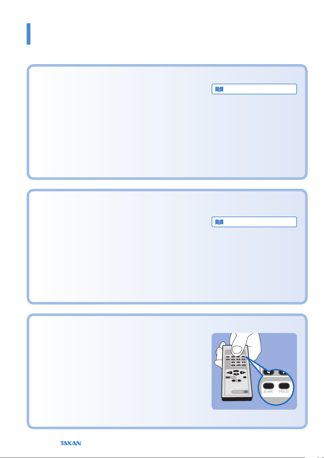
I would like to stop the projection temporarily.
The projection can be stopped temporarily during a presentation or class.
By using Still Image (FREEZE), or Blank/Mute (BLANK) the projection can
be paused, or the video can be made blank temporarily.
See “Temporarily Blanking/Muting the Video/Audio”, or “Pausing the Video”
for information about operation from the remote control. See Pages E-40
and 41.
See “Blank/Mute” or “Still Image” for information about operation from the
menu. See Page E-57.
E-8
Data Projector
Helpful Hints
KG-PS232Xh/232X only
Convenient functions for the use of this product
I would like the lamp to have a longer life.
The life of the lamp can be maintained longer by using the Eco Mode to limit
the power consumption of the projector.
See “Eco Mode” for information about operation from the remote control.
See Page E-42.
See “Eco Mode” for information about operation from the menu. See Page
E-56.
I would like to put away the projector right after using it.
The projector is equipped with a Quick-o function. After turning o the
power, the fan will continue to turn to cool the lamp even when the power
cable has been disconnected.
See “The Procedure from Projection to Turning O the Power” for details
about the Quick-o function. See Page E-24.
What is the Quick-o function?
The projector is equipp ed with a Quick-o function. Even
when the power cable is unplugged soo n after turning o
the power, the internal power supply will power the rotation
of the coolin g fan and cool the lamp allowing immediate
removal.
Technical Point
Theft and mischief are concerns.
This projector is equipped with security lock functions that allow it to be
used more safely including a theft-prevention lock compatible with the
Kensington MicroSaver® security system, and a password setting
See “Names of the Projector Parts and their Functions” for details about the
theft-prevention lock. See Page E-18.
See “Set Password” for information about setting the password. See Page E-
75.
Technical Point
What is a password setting?
This projec tor is equipped wi th a function that can restrict
the star t-up of the p rojector by setting a password to avoid
mischief and unau thorized use.
When a password has been set, upon starting the projector a
password entry screen will be displayed. Use of the projector
will not be possi ble unless the password is entered.
KG-PS232Xh/232 X | KG-PV131X/131S User’s Manual
E-9

KG-PS232Xh/232X only
Finding Information with the Remote Control and the Projector Control Panel
KG-PS232Xh/232X only
KG-PS232Xh/232X only
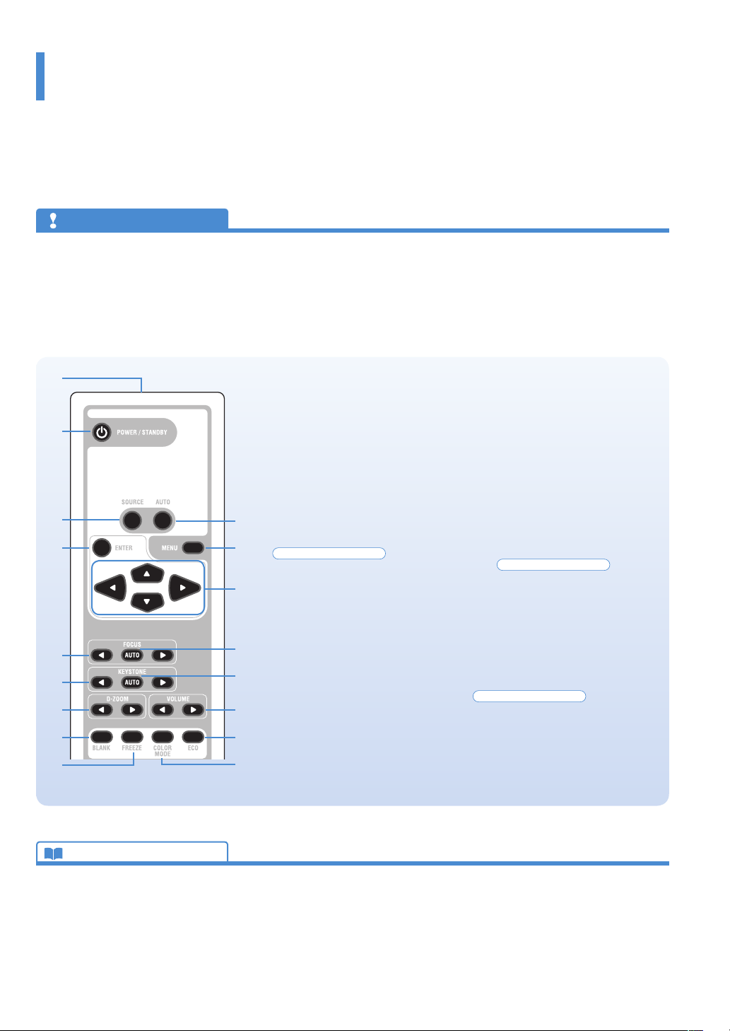
Finding Information with the Remote Control
Infrared transmitter
POWER/STANDBY button
This button is used to switch on the
power and set the projector to the
STANDBY mode. See Page E-34.
SOURCE button
This button selects the input source.
See Page E-39.
ENTER button
This button is used to execute menu
operations, etc.
FOCUS button
This button operates the focus manually.
See Page E-42.
KEYSTONE buttons
These buttons operate the keystone
correction manually. See Page E-43.
AUTO button
This automatically adjusts the video.
(Usually, the video is adjusted automatically at the time of signal selection.) See Page E-39.
*Only the RGB signal is adjustable.
MENU button
This button selects the menu display.
See Page E-47.
Cursor buttons
These buttons perform the menu
operations.
AUTO FOCUS button
This button adjusts the focus automatically.
See Page E-40.
AUTO KEYSTONE button
This button corrects the keystone distortion automatically. See Page E-40.
D-ZOOM buttons
These buttons adjust the digital zoom.
See Page E-44.
BLANK button
This button temporarily blanks the
video and mutes the audio. See Page
E-40.
FREEZE button
This button pauses the video. See
Page E-41.
Technical Point
What is BLANK?
It is a functi on that temporari ly makes the screen go blank
during video projection. This is convenient when you would
like to temporarily blank the video when projecting to a
white board, etc.
See “Te mporarily Blanking/Muting the Vid eo/Audio” for details. See Page E-40.
What is FREEZE?
It is a function that temporarily stops the projected vi deo.
This is a convenient function that allows you to temporarily
stop the video and look for a document should you wish to
nd another docu ment when projecting a document with
the personal computer.
See “Pausing the Video” for details. See Page E-41.
VOLUME buttons
These buttons perform the volume
adjustment. See Page E-43.
ECO button
This button switches to the Eco mode.
See Page E-42.
COLOR MODE button
This button displays the projection
mode menu. See Page E-41.
What is COLOR MODE?
It is a function that automatically adjusts optimum color
tone in conjunction with the projection circumstances. For
example, when projectin g to a blackboard, selecting the
Blackboard mode wi ll automatically set the optimum
color adjustment to a b lackboard.
See “Projection Mode Selection” for details. See Page E-41.
E-10
Data Projector
Finding Information with the Remote Control and the Projector Control Panel
KG-PS232Xh/232X only
KG-PV131X/131S only
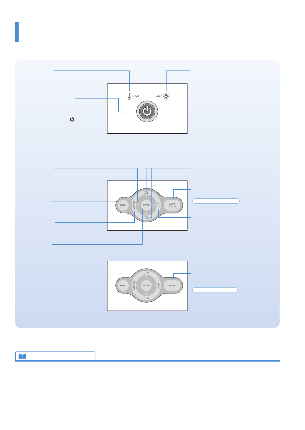
Finding Information with the Projector Control Panel
HEAT indicator
This is an indicator that indicates faults
related to the temperature of the projector.
See Page E-83.
POWER/STANDBY button
This button is used to switch on the power
and set the projector to the STANDBY
mode. See Page E-34.
The power supply symbol of the POWER/STANDBY button serves as an indicator
that indicates the on/o status of the Eco
mode, the temperature, and lamp faults.
Eco Mode: See Pages E-42 and E-56.
Indications of the indicator: See Page E-83.
Cursor buttons
These buttons perform the menu operations. (They are allocated to other functions when the menu screen is not being
displayed.)
MENU button
This button selects the menu display.
See Page E-47.
SOURCE button
This button displays the input source
screen. See Page E-39.
ENTER button
This button is used to execute menu operations, etc.
LAMP indicator
This is an indicator that indicates faults
related to the lamp. See Page E-83.
KEYSTONE buttons
These buttons operate the keystone correction manually. See Page E-43.
AUTO FOCUS button
This button adjusts the focus automatically.
See Page E-40.
AUTO button
This automatically adjusts the video. (Usually, the video is adjusted automatically at
the time of signal selection.) See Page E-39.
* Only the RGB signal is adjustable.
Technical Point
What is the menu display?
The menus of this projec tor include the two types of Simple Menu and Advanced Menu.
Simple Menu includes a collection of frequently used functions. In cluded are On/O switch-
ing of Auto Keystone and Auto Focus, Projec tion Mode and other items. On the contrary,
the Advanced Menu includes infrequently used set tings such as ne adjus tments of the image and Set Password, etc.
See “Using the Menu” for details. See Page E-46.
BLANK button
This button temporarily blanks the video
and mutes the audio.
See Page E-40.
What is Keystone Distortion?
Keystone distortio n is distortion of the projec ted image that occurs when the p rojector is tilted
vertically or ho rizontally with respect to the screen.
There are two t ypes of keystone distor tion, in the hori zontal direction when the projector is
slanted to the left or right, an d in the vertical direction when th e projector is tilted up or down.
This projector can manual ly or automatically correct the distor tion in the vertical direction .
See “Auto Keystone”, and “Keystone” for details. See Pages E-53 and 54.
KG-PS232Xh/232 X | KG-PV131X/131S User’s Manual
E-11
Finding Information with the Remote Control and the Projector Control Panel
Finding Information from the Operations Screen
This section describes menu viewing and operation. Please see the various explanatory pages about menu functions and
adjustment/setting methods. To use the remote control, direct it towards the remote control infrared sensor of the projector
and operate it.
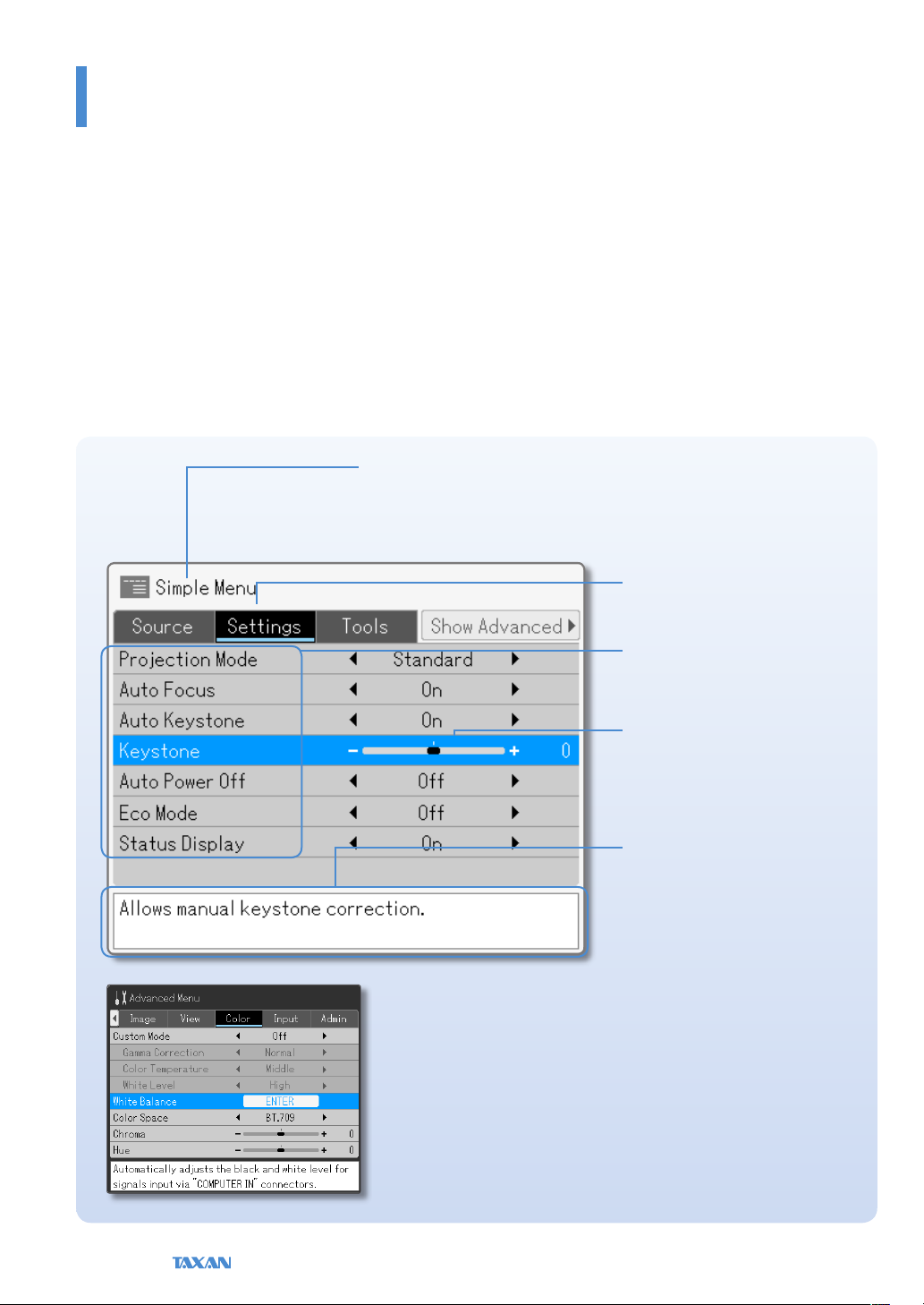
Menu Screen Names and Functions
This projector has two types of menu, a Simple Menu that enables operation of basic functions, and an Advanced Menu that
enables detailed settings such as image settings, etc. Since the operation method is the same for both types, the Simple Menu
will be used here to describe the names and functions of the menu screen.
With respect to the Simple and Advanced screens,
Simple Menu has a light gray background color. Select-
ing Show Advanced will change the display to the
Advanced Menu.
Menu Name
This is the title of the menu. The color
of the selected menu will change.
Advanced Menu
In the Advanced Menu the menu background color changes from light gray to
deep gray.
Item Name
This is the name of the adjustment or
setting. The (blue) cursor will move to
the selected item.
Adjustment Bar and Settings
Contents
The increases and decreases in bar
length express the adjustment condition. The set contents are displayed in
characters.
Help
A Help explanation related to the
selected menu/item is displayed.
E-12
Data Projector
Finding Information with the Remote Control and the Projector Control Panel
Finding Information from the Operations Screen
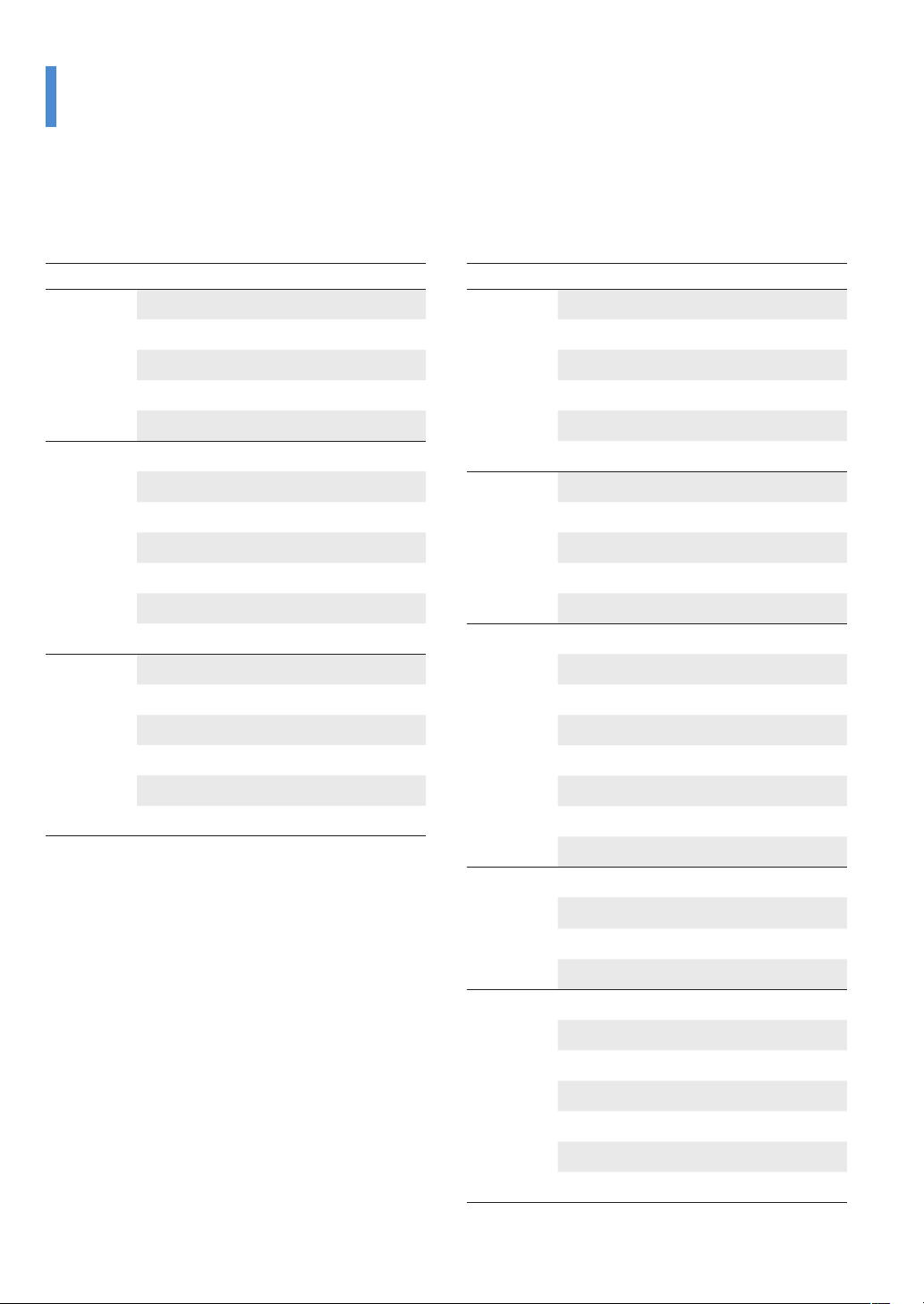
Menu Item List
Simple Menu
Menu Name Item Name Page
Source Auto Detect E-51
Manual selection Computer1 E-51
Computer2 E-51
Video E-51
S-Video E-51
Settings Projection Mode E-52
Auto Focus
Auto Keystone E-53
Keystone E-54
Auto Power O E-55
Eco Mode
Status Display E-56
Tools Blank/Mute E-57
Still Image E-57
Zoom E-58
Timer Display E-60
Volume E-61
Select language E-62
E-53
E-56
Advanced Menu
Menu Name Item Name Page
Image Brightness E-63
Contrast E-63
Sharpness E-63
Frequency Compensation E-64
Phase Control E-65
Denition E-65
View Select Aspect Ratio E-66
Horizontal Position E-68
Vertical Position E-68
Vertical Flip E-68
Horizontal Flip E-68
Color Custom Mode E-69
Gamma Correction E-69
Color Temperature E-70
White Level E-70
White Balance E-71
Color Space E-72
Chroma E-72
Hue E-73
Input Computer1 E-74
Computer2 E-74
Video E-74
S-Video E-74
Admin Set Password E-75
Version E-78
Lamp Timer E-79
Lamp Timer Reset E-80
Initialize E-81
Startup Screen E-81
Background Color E-82
KG-PS232Xh/232 X | KG-PV131X/131S User’s Manual
E-13

Finding Information with the Remote Control and the Projector Control Panel
Finding Information with Keywords
Keyword Page
Advanced Menu E-50
Aspect Ratio E-66
AUTO E-39
AUTO FOCUS E-40
Auto Focus function E-40, 53
AUTO KEYSTONE E-40
Auto Keystone (Auto keystone correction) E-40, 53
Auto Power O E-55
Background Color E-82
BLANK E-40
Blanking of the video E-41, 57
Blanking/Muting of the video/audio E-40, 57
Blurred Screen E-37
Ceiling suspension setting E-68
Chroma E-72
COLOR MODE E-41
Color Space E-72
Color Temperature E-70
Computer 1/2 E-51, 74
Contrast E-63
Digital Zoom E-44, 58
D-ZOOM E-44
ECO E-42
Eco Mode E-42, 56
Flashing indicator E-83
Focus E-37, 42
FOCUS E-42
FREEZE E-41
Frequency E-64, 94
Gamma E-69
HEAT E-83
Hue E-73
Keyword Page
Initial Setting E-34
Initialize E-81
Input source E-39, 51
KEYSTONE E-43
Keystone (Keystone correction) E-43, 54
Keystone distortion E-40, 43, 53, 54
LAMP E-83
Lamp replacement E-87
Language E-62
MENU E-47
No signal E-27
Notebook computer external output signal E-27
Phase E-65
POWER/STANDBY E-10, 11, 22
Projection Mode E-41, 52
Quick-o function E-24
Rear Projection E-68
RS-232C connector E-32
Sharpness E-63
Simple Menu E-49
Source E-39, 51
SOURCE E-39
Standby E-33
Startup Screen E-81
Status Display E-56
Timer E-60
Video/S-Video E-51, 74
Volume E-43, 61
VOLUME E-43
White Balance E-71
White Level E-70
E-14
Data Projector
Check before Use
Check the Accessories
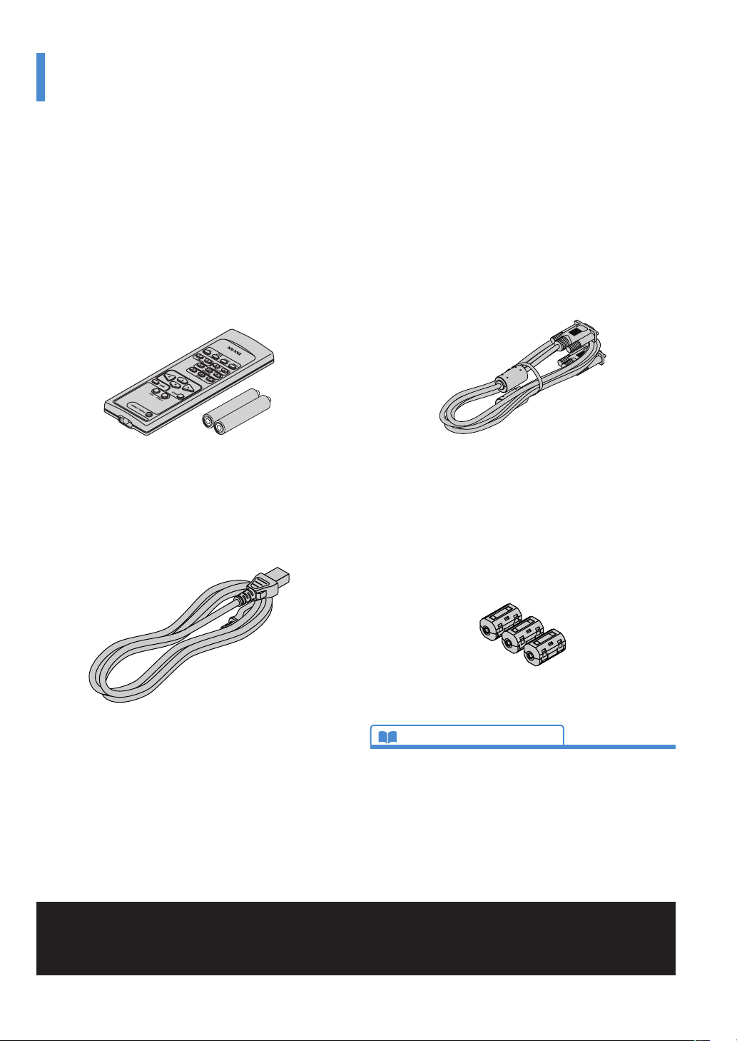
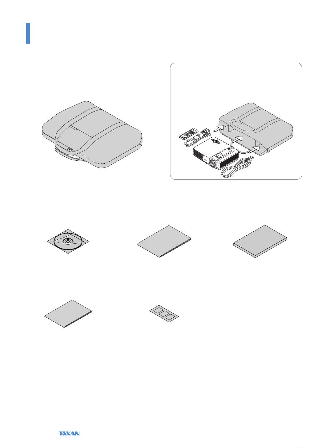
Remove the projector and the accessories from the box and check that the following items are included.
*The supplied power cable is a dedicated product for this projector. Never use it with another product.
Remote control (including two AA batteries) [1]
This remote control is used for projector operation. See Page
E-19.
Power cable (1.8 m / 5.9 feet) [1]
This power cable supplies power to the unit.
See “ Turning On the Power” for connection information. See
Page E-33.
RGB signal cable (Mini D-Sub 15-pin, 2 m / 6.6 feet) [1]
This is used for making connections with a personal computer. See “Connections with a Personal Computer” for connection information. See Page E-26.
Ferrite core [3]
These ferrite cores are attached to the two power cables and
either one of the video cable or S-video cable.
See “Attaching the Ferrite Core” for details. See Pages E-28
and 33.
Technical Point
What is a ferrite core?
These a re acces sories that are used to reduce the radiated noise from the inter face cables of
digital equipment a nd other devices. When a high frequency current that is the source of noise
ows in a cable, it will generate a magnetic eld an d noise will be emitted. The ferrite core
absorbs t his and conver ts it to heat which is radiated. Attaching a ferrite core will reduce the
deterioration of the pi cture.
“WARNING”
Handling the cables supplied with this product, will expose you to lead, a chemical known to the State of California to cause
birth defects or other reproductive harm.
Wash hands after handling.
KG-PS232Xh/232 X | KG-PV131X/131S User’s Manual
E-15
Check before Use
Check the Accessories
Soft Case [1]
This case will hold the projector, the accessories, and the
user’s manual.
User’s manual (CD-ROM edition)
[1]
Startup Guide [1] Safety and Support Service Guide
Item Insertion
Close the lens shutter of the projector and place the
projector in the case with the lens facing upward. Place
the accessories in the storage pocket.
[1]
Security Sheet [1] Security Label [1]
E-16
Data Projector
Check before Use
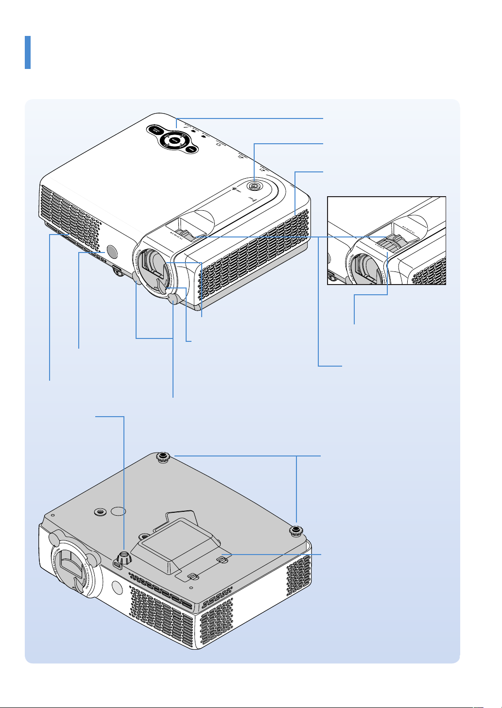
Names of the Projector Parts and their Functions
KG-PS232Xh/232X Projector control panel
See Page E-11
POWER/STANDBY button
See Page E-33
Ventilation slots
KG-PV131X/131S
Remote control sensor
Exhaust vents
Front adjuster
Adjusts the projection
angle. See Page E-36.
Lens
Lens shutter
This shutter protects the lens. Closing
the shutter during projection will automatically activate Blanking/Muting
of the video/audio. See Page E-33.
Focus sensor
Focus ring
Adjusts the focus of the screen
picture. See Page E-37.
Zoom ring
Adjusts the size of the screen
picture. See Page E-36
Rear adjusters
Adjust the projection angle. See Page
E-36.
Lamp cover
See “Replacing the Lamp Cartridge”
for information about how to replace
the lamp. See Page E-87.
KG-PS232Xh/232 X | KG-PV131X/131S User’s Manual
E-17

Check before Use
Names of the Projector Parts and their Functions
AC IN connector
See Page E-33
Built-in Security Slot
This is compatible with the MicroSaver® security system manufactured
Ventilation slots
by Kensington Computer Products
Group. (See below)
Remote control sensor
AUDIO IN connector
See Page E-30
VIDEO IN connector
See Page E-28
S-VIDEO IN connector
See Page E-28
RS-232C connector
This connector is used
for projector control. See
Page E-32
COMPUTER IN connector
See Page E-26
MONITOR OUT connector
This connector is used for
video output. See Page E-31
Built-in Security Slot
This security slot supports the MicroSaver Security System manufactured by Kensington Microware Inc.
E-18
Data Projector
Check before Use
KG-PS232Xh/232X only
KG-PS232Xh/232X only
KG-PS232Xh/232X only
Names of the Remote Control Parts and their Functions
Two types of remote control are available for this product.
Here, the description will be based on the remote control for model KG-PS232Xh/232X.
* The remote control for model KG-PV131X/131S does not include some of the buttons. See description below for details.
Precautions
Do not drop the remo te control or handle it inappropriately.
•
Do not expose the remote control to water or other liquids. Shou ld the remote control become wet, wipe it dr y immediately.
•
Try to avoid use in hot and /or humid locations.
•
Please keep batteries o ut of the reach of children. If a b attery is swallowed, promptly obtain the medical care of a doctor.
•
Remove the battery f rom the remote control when it is not go ing to be used for a long period.
•
Some operations (s uch as menu operations) are available on ly through the use of the remote control and attention should be given to its c areful handling.
•
1
2
3
4
5
6
7
8
9
1. Infrared transmitter
2. POWER/STANDBY button
This button is used to switch on the
power and set the projector to the
STANDBY mode. See Page E-34.
3. SOURCE button
This button selects the input source. See
Page E-39.
4. ENTER button
This button is used to execute menu
operations, etc.
10
5. FOCUS button
This button operates the focus manually.
11
See Page E-42.
6. KEYSTONE buttons
12
These buttons operate the keystone correction manually. See Page E-43.
7. D-ZOOM buttons
These buttons adjust the digital zoom.
See Page E-44.
13
8. BLANK button
This button temporarily blanks the video
14
and mutes the audio. See Page E-40.
9. FREEZE button
This button pauses the video. See Page
15
E-41.
16
17
10. AUTO button
This automatically adjusts the video.
(Usually, the video is adjusted automatically at the time of signal selection.) See
Page E-39.
* Only the RGB signal is adjustable.
11. MENU button
This button selects the menu display.
See Page E-47.
12. Cursor buttons
These buttons perform the menu operations.
13. AUTO FOCUS button
This button adjusts the focus automatically.
See Page E-40.
14. AUTO KEYSTONE button
This button corrects the keystone distortion automatically. See Page E-40.
15. VOLUME buttons
These buttons perform the volume
adjustment. See Page E-43.
16. ECO button
This button switches to the Eco mode.
See Page E-42.
17. COLOR MODE button
This button displays the projection
mode menu. See Page E-41.
Technical Point
What is BLANK?
It is a functi on that temporari ly makes the screen go blank
during video projection. This is convenient when you would
like to temporarily blank the video when projecting to a
white board, etc.
See “Te mporarily Blanking/Muting the Vid eo/Audio” for details. See Page E-40.
What is FREEZE?
It is a function that temporarily stops the projected vi deo.
This is a convenient function that allows you to temporarily
stop the video and look for a document should you wish to
nd another docu ment when projecting a document with
the personal computer.
See “Pausing the Video” for details. See Page E-41.
What is COLOR MODE?
It is a function that automatically adjusts optimum color
tone in conjunction with the projection circumstances. For
example, when projectin g to a blackboard, selecting the
Blackboard mode wi ll automatically set the optimum
color adjustment to a b lackboard.
See “Projection Mode Selection” for details. See Page E-41.
KG-PS232Xh/232 X | KG-PV131X/131S User’s Manual
E-19
Check before Use
Preparing the Remote Control
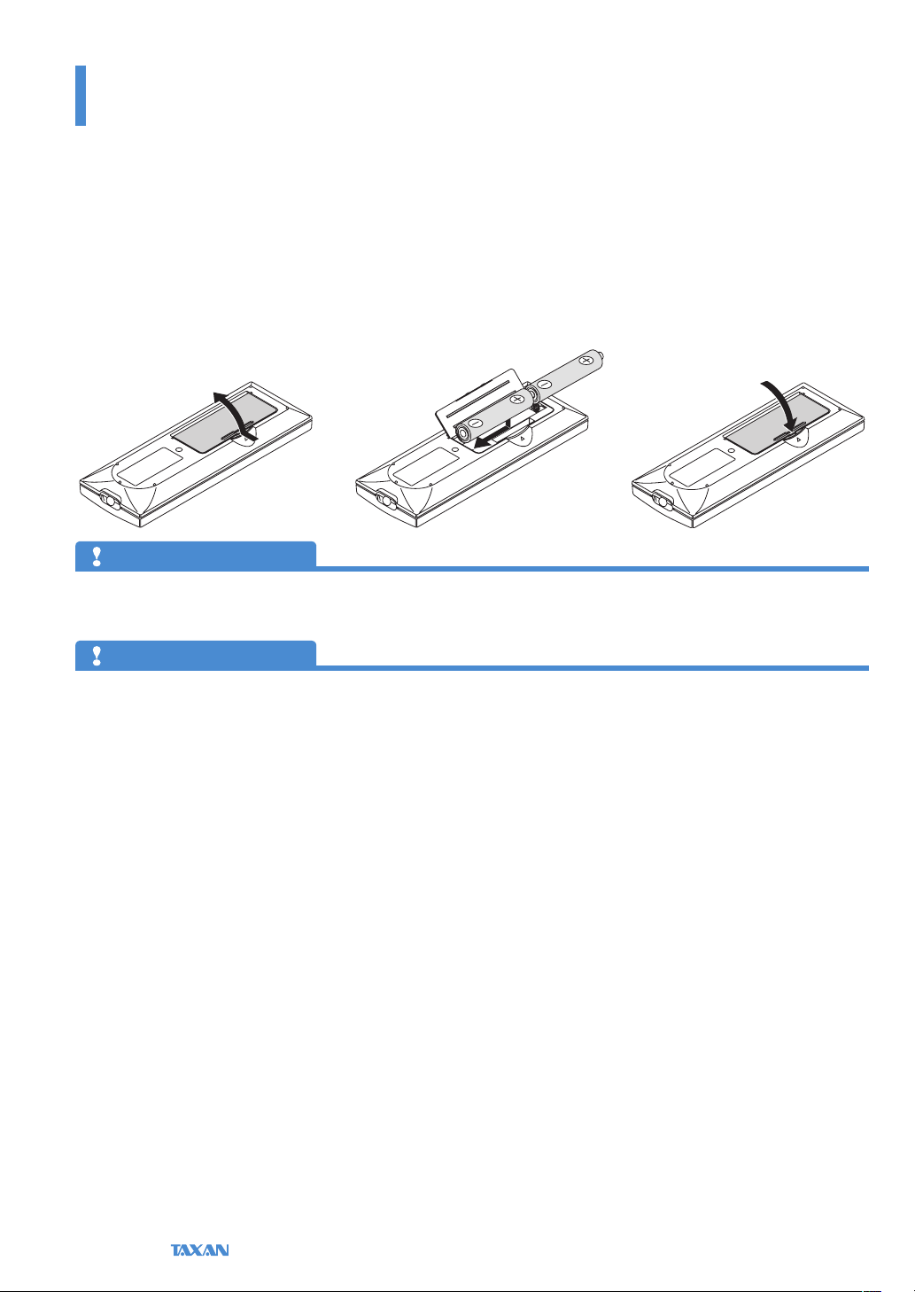
Installing the Batteries (and Battery Replacement)
The projector and the batteries are packaged separately. Insert the batteries in the remote control before use.
When it is time to replace the batteries, do so using the same procedure.
1. Open the cover of the battery
case located on the back of the
remote control.
Precautions
Use the same type of replacement batteries as the suppli ed AA batteries. There is danger of explosion i f dierent battery types are used.
•
Dispose of used batteries according to the local regulatio ns.
•
Note
Exposure of the main unit’s remote control sensor or the remote control inf rared transmitter to bright light or the obstruction of the signal by an obstacle located in the
•
pathway may prevent operation. To prevent operational diculties w ith the sensor when the projector is installed suspended from the ceiling, ins tall the projector 1.5
m (4.9 feet) or fu rther from uorescent lighting.
The remote control will n ot function properly when the batteries are weak.
•
2. Insert the batteries so that +
and − ends match the markings
inside the case.
3. Close the cover of the battery
case.
E-20
Data Projector
Basic Operation
The Procedure from Projection to Turning O the Power
Basic Operation
This section provides a simple description of the method of operation from projector setup, to video projection, and nishing up. For the detailed operational
methods of the various operations, please see the respective pages with the description.
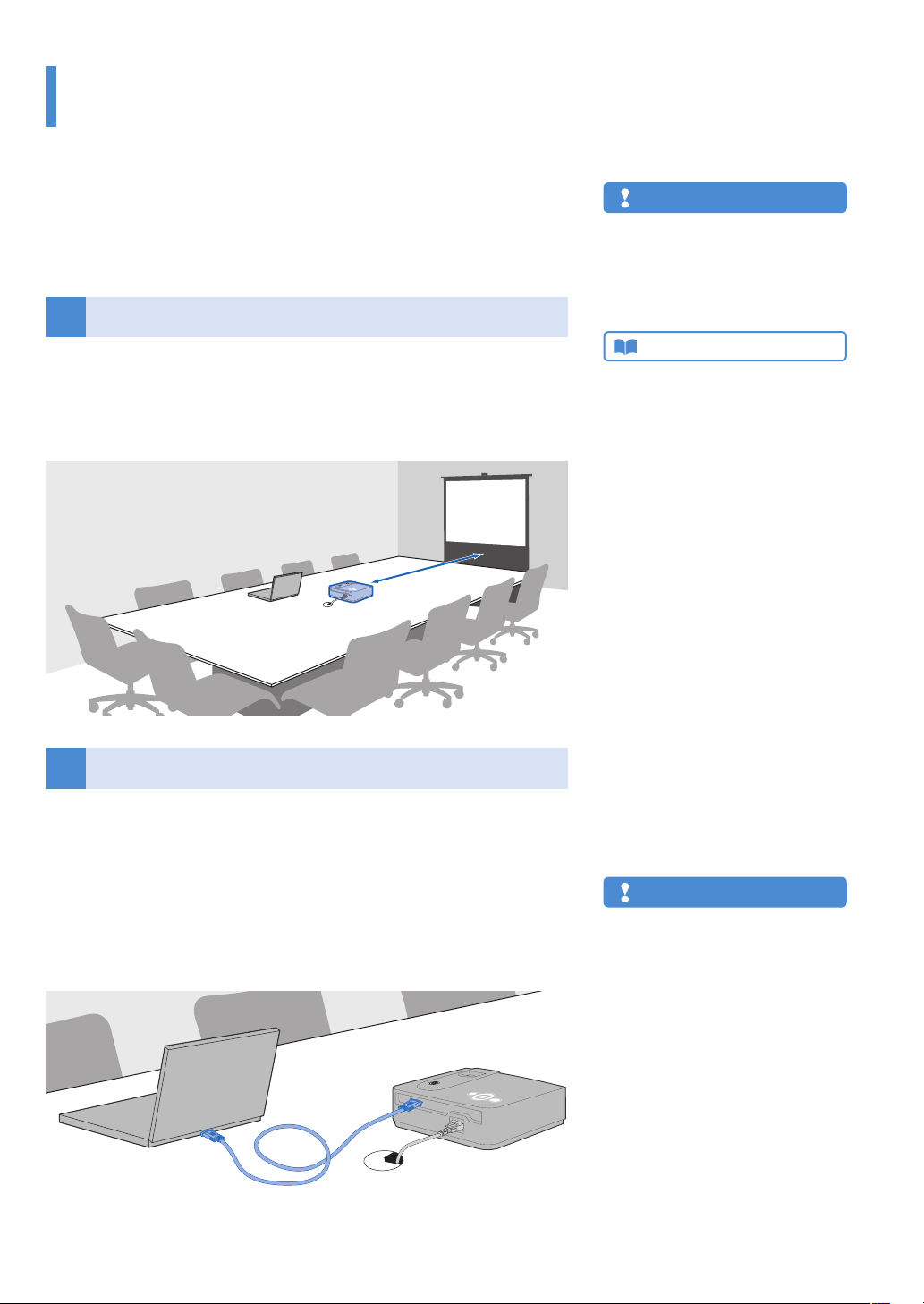
Placement
1
Determine the setup locations of the screen and the projector and set up the
items.
See “Screen Size and Projection Distance” for information about distance and placement considerations at the time of setup. See Page E-25.
Connecting Personal Computers and Video Equipment
2
Connect the projector and your equipment.
To make connection with the RGB connector of a personal computer, see Con-
•
nections with Personal Computer on Page E-26.
To make connection with the video connector (RCA jack) of video equipment,
•
or an S-video connector, see “Connections with Typical Video Equipment” on
Page E-28.
To make connection with the YCbCr connector, or YPbPr connector of video
•
equipment, see “Using YCbCr Connectors or YPbPr Connectors” on Page E-29.
Note
In conside ration of quality, perfection is expect-
•
ed, but very rarely black or bright dots may exist
among the pixels of DLP® t ype projectors. Thank
you for your understandi ng.
Please purchase a s creen separately.
•
Technical Point
What is an RGB connector?
This is a connector used for transferri ng video signals to
a monitor or other equipment. The three col ors R (red), G
(green), and B (blue) are separated and transf erred as an
analog signal with this system. The display of a personal
computer is expressed by the RGB color spa ce, and synthesizing the three colors perm its all colors to be reproduced.
These conne ctors mainly use a standard called mini D-Sub
15-pin that describes their form, and control signals used for
signal synchronization, as well as other sign als, are transferred at the same time as the RGB color signal.
What is a Video Connector, an S-connector,
a YCbCr Connector, and a YPbPr Connector?
Several types of connectors are used as video connectors
including composite video connectors, separate video connectors, and component video connectors.
Composite video connectors are usually called pin jacks or
RCA jacks, and they are mainly included on video decks,
document cameras, etc.
Separate video connec tors are most typically called S-video,
and becau se they take the form of mini DIN 4-pin con nectors, mini DIN 4-pin m ay also be used to describe S-video.
Component video conne ctors are called color-dierence
input connectors. The us ual NTSC (480i) signal connector
that transfers the C color signal wh ich is divided into the B-Y
color-dierence signal Cb (P b), and the R-Y color-dierence
signal Cr (Pr) is described as Y/Cb/Cr. Connectors that can
be used for video f ormats above NTSC may be described as
Y/Pb/Pr.
Note
A commercially-availab le component cable is re-
•
quired to make con nection with equipment h aving YCbCr connectors suc h as DVD players, etc.
A commercially-available component cable is
•
required to make con nection with equipmen t
having YPbPr connectors such as high denition
video equipment, etc.
KG-PS232Xh/232 X | KG-PV131X/131S User’s Manual
E-21
Basic Operation
The Procedure from Projection to Turning O the Power
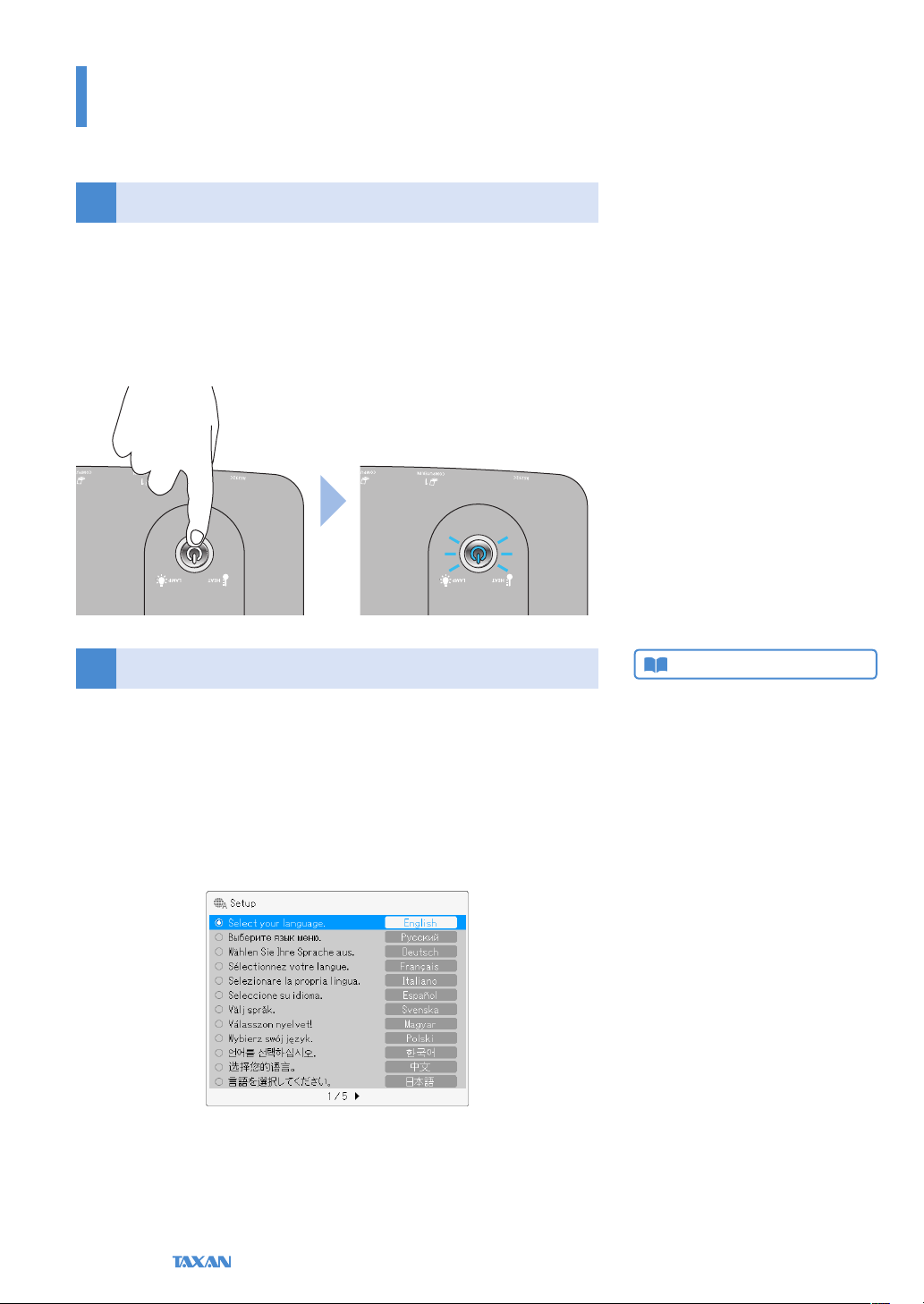
Turn On the Power
3
Press the POWER/STANDBY button of the remote control or the projector and turn
on the power.
The indicator of the POWER/STANDBY button will change from the orange color of
the standby mode to (ashing) blue. See “Turning On the Power” for details about
when the power is turned on. See Page E-33.
The Video Is Projected
4
Language Settings and other initial settings will be displayed only when the
power is turned on for the rst time after purchase. See “Turning On the Power for
the First Time after Purchase” on Page E-34.
The factory default setting is for Automatic Detection be On. This will automatically project the video when an input signal is detected.
When attempting to project video from a notebook computer, and video is not
•
projected, see “To Output the External Output Signal of a Notebook Computer”
on Page E-27.
Technical Point
The projector is equipped with a Quick-star t function. The
Quick-start function is a function that projects the video a
short time a fter pressing the POWER/STANDBY button.
The video w ill be projected a little over ten seconds after
pressing the POWER/STANDBY button.
E-22
Data Projector
Basic Operation
The Procedure from Projection to Turning O the Power
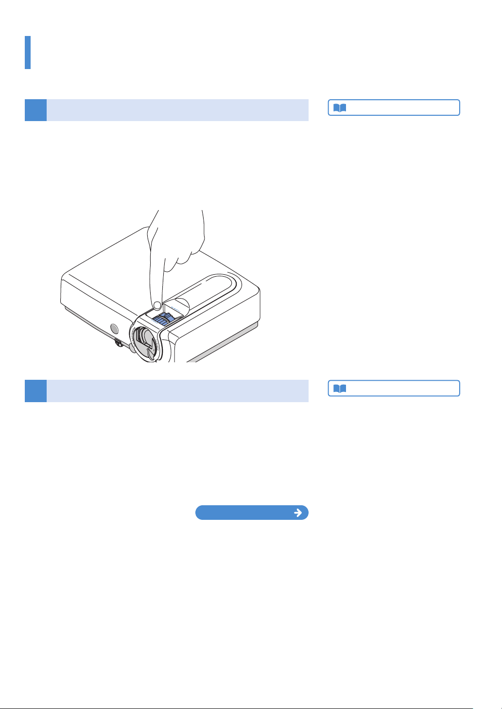
Properly Adjusting the Projected Image to the Screen
5
Model KG-PS232Xh/232X is equipped with an Auto Focus function. This func-
•
tion automatically adjusts the focus when the size of the projected image is
adjusted with the zoom ring.
Since model KG-PV131X/131S does not have an Auto Focus function, please
•
adjust the size of the projected image with the zoom ring, and adjust the focus
with the focus ring. See “Adjusting the Focus” on Page E-37 for details.
Adjusting Images and Video
6
Adjust the video to the optimal condition as required.
AUTO button: Automatically adjusts the image of the RGB signal.
•
“Automatic Adjustment” See Page E-39.
Projection Mode: Can select a projection mode to suit the purpose.
•
“Projection Mode selection” See Page E-41.
Advanced Menu: Allows more detailed video settings to be made such as Im-
•
age, and Color. “Advanced Menu” See Page E-63.
Technical Point
What is the Auto Focus function?
Model KG-P S232Xh / 232X is equ ipped with an Auto
Focus function. The Auto Focu s function is a fun ction that
measures the dista nce to the screen and performs the fo cus adj ustment automatically. Auto Focus uses the infrared
sensor at the front o f the projector to determine the screen
position and adju st the focus.
See “Auto Focus” for information ab out the setting method.
See Page E-53.
Technical Point
What is the projection mode?
It is a function that automatically adjusts optimum color
tone in conjunctio n with the projection circumstances.
For example, when projec ting to a blackboard, selecting
the Blackbo ard mode will au tomatically set the optimum
color adjustment to a b lackboard.
Continued on next page
KG-PS232Xh/232 X | KG-PV131X/131S User’s Manual
E-23
Basic Operation
The Procedure from Projection to Turning O the Power
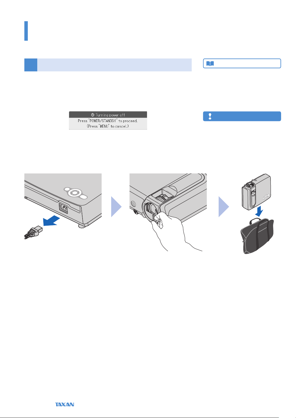
Turn O the Power after Projection is Finished
7
After projection is nished, press the POWER/STANDBY button to turn o the
power.
This message will be displayed: Turning power o – Press "POWER/STANDBY" to
proceed. (Press "MENU" to cancel.)
A press of the POWER/STANDBY button cause the screen to go blank and will enter
the projector into the power o operation. When the Quick-o function is not being used, check that the POWER/STANDBY button indicator is lit in orange in the
standby mode and then disconnect the power cable. When the power cable is
disconnected, the indicator of the POWER/STANDBY button will go o.
Technical Point
What is the Quick-o function?
The projector is equipp ed with a Quick-o function. Even
when the power cable is unplugged soo n after turning o
the power, the internal power supply will power the rotation
of the coolin g fan and cool the lamp allowing immediate
removal.
Note
After cooling the projector wit h the power cable
•
connected, relightin g of the lamp might become
dicult.
Do n ot place the projector in a bag or other en-
•
closure while the co oling fan is turning.
E-24
Data Projector
Basic Operation
31.3"
40"
60
"
80"
100"
120"
150"
200"
250
"
1.20 (3.94)
1.33–1.54
(4.36
–5.05)
2.00
–2.33
(6.56
–7.64)
2.69
–3.12 (8.8
3
–10.24)
3.38
–3.91 (11.09
–12.83)
4.06
–4.69 (13.32
–15.39)
5.08
–5.88 (16.67
–19.29)
6.79
–7.85 (22.28
–25.75)
8.49
–9.82 (27.85
–32.22)
10.20
–11.79 (33.46
–38.68)
h2
h1
300"
Placement
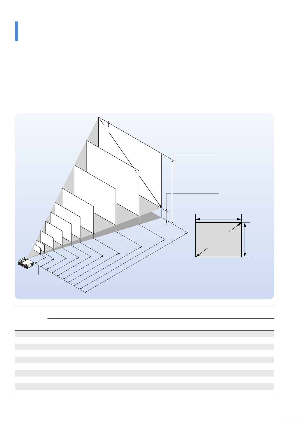
Use this information as a guide to nd out about what the screen size will be for the projected video when placing the
•
projector.
The projection distance over which focusing is adjustable is 1.20 m (3.9 feet) to 11.79 m (38.65 feet) from the projector lens
•
surface. The projector should be placed within this range.
It will be necessary to change the projection method when the projector is installed suspended from the ceiling. See “Verti-
•
cal Flip / Horizontal Flip”. See Page E-68.
Screen Size and Projection Distance
Screen Size Designation (Inches)
Height from center of
lens to top edge of the
projection
Height from center of
lens to bottom edge of
the projection
Width
Screen size
(Diagonal)
Lens surface of
the main unit
Unit: m (feet)
There is a tolerance of ±5% due to
•
design values.
This table uses the lens apex and lens
•
center as references and requires that
the projector be in a horizontal condition (with front and rear adjusters fully
withdrawn).
Screen Size
Designation
(Inches)
31.3" 0.64 × 0.48 2.09 × 1.57 — – 1.20 — – 3.94 0.53 1.73 0.05 0.16
100" 2.03 × 1.52 6.67 × 5.00 3.38 – 3.91 11.09 – 12.83 1.68 5.52 0.16 0.52
120" 2.44 × 1.83 8.00 × 6.00 4.06 – 4.69 13.32 – 15.39 2.02 6.62 0.19 0.62
150" 3.05 × 2.29 10.00 × 7.50 5.08 – 5.88 16.67 – 19.29 2.53 8.29 0.24 0.79
200" 4.06 × 3.05 13.33 × 10.00 6.79 – 7.85 22.28 – 25.75 3.36 11.02 0.31 1.02
250" 5.08 × 3.81 16.67 × 12.50 8.49 – 9.82 27.85 – 32.22 4.20 13.78 0.39 1.28
300" 6.10 × 4.57 20.00 × 15.00 10.20 – 11.79 33.46 – 38.68 5.04 16.54 0.47 1.54
40" 0.81 × 0.61 2.67 × 2.00 1.33 – 1.54 4.36 – 5.05 0.67 2.20 0.06 0.20
60" 1.22 × 0.91 4.00 × 3.00 2.00 – 2.33 6.56 – 7.64 1.00 3.30 0.09 0.30
80" 1.63 × 1.22 5.33 × 4.00 2.69 – 3.12 8.83 – 10.24 1.35 4.43 0.13 0.43
Screen Size
Width × Height
(m) (feet) (m)
Wide – Tele
Projection Distance Height h1 Height h2
(feet)
Wide – Tele
(m) (feet) (m) (feet)
Height
KG-PS232Xh/232 X | KG-PV131X/131S User’s Manual
E-25
Basic Operation
Connecting Personal Computers and Video Equipment
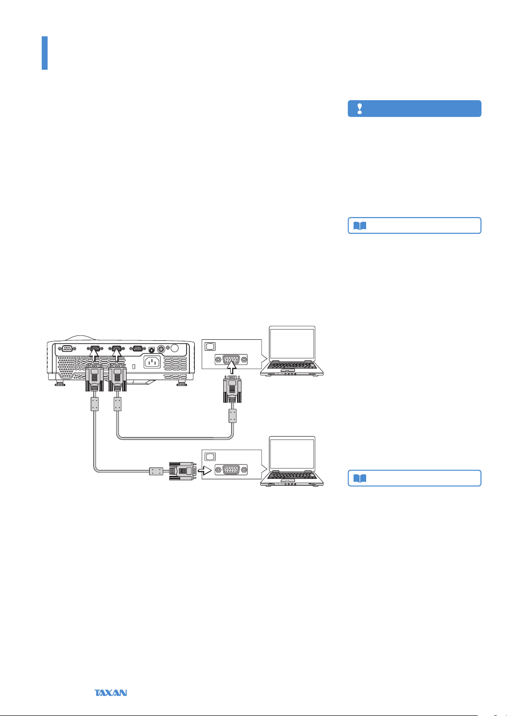
Connections with the Personal Computer
Connecting the projector with a personal computer permits the video of the personal computer to be projected to a large sized screen at meetings, lectures, and
on other occasions.
Please check the following before making connections with the personal computer.
An appropriate resolution for the KG-PV131S is 800 × 600 dots (S-VGA), and the
•
maximum displayable resolution is 1024 × 768 dots (XGA).
An appropriate resolution for the KG-PS232Xh/232X and KG-PV131X is 1024
•
× 768 dots (XGA), and the maximum displayable resolution is 1280 × 1024 dots
(S-XGA).
Please change to a displayable resolution at the PC side when the aforementioned
maximum displayable resolution is exceeded. See “Table of Supported Frequency”
for details. See Page E-94.
The screen resolution setting method of the personal computer will dier depending on the specic model. Please read the personal computer instruction manual
or the on-line help information, or contact the manufacturer of your personal
computer.
Monitor Output
Personal computer
RGB signal cable
(Commercially-available)
Monitor Output
Personal computer
Note
Use of a cable longer than the supplied RGB cable
•
or extension of the cable might result in the generation of noise or deterioration of the image.
When a lo ng cable is used, we recommend the
use of a noise canceller or other devices. Contact
an installer or o ther professional for details.
Setting the output freq uency of the personal
•
computer to 60 Hz will result in the display of the
clearest video.
Technical Point
What is an RGB connector?
This is a connector used for transferri ng video signals to
a monitor or other equipment. The three col ors R (red), G
(green), and B (blue) are separated and transf erred as an
analog signal with this system. The display of a personal
computer is expressed by the RGB color spa ce, and synthesizing the three colors perm its all colors to be reproduced.
These conne ctors mainly use a standard called mini D-Sub
15-pin that describes their form, and control signals used for
signal synchronization, as well as other sign als, are transferred at the same time as the RGB color signal.
What are supported frequencies?
Supported frequencies is a term that indicates the breadth
of the scanning frequencies that this projector su pports. The
scanning frequenci es express the speed when the display is
drawing the screen. The number of lines that can be drawn
in 1 second are called the h orizontal scanning frequency, and
the number of t imes the screen is overwritten in 1 second is
called the vertical scanning f requency. The higher the scanning frequenc y, the higher t he resolution or the greater the
number of simult aneously expressed colors can will b e possible, and a display having little icker can be produced. As
an example, a display having a ver tical scanning f requency
of 70 Hz can draw the screen 70 times in 1 second.
RGB signal cable (Supplied item)
Connect the COMPUTER IN 1/2 connector of the projector with the video output
connector of the personal computer using the supplied RGB signal cable or a commercially-available one.
When making connections, align the orientation of the connectors and insert
•
them. Then, turn the knobs and secure to the connector of the projector.
The factory default input signal setting is set to Auto; however, if there is no
•
projection, change the setting of the input signal to Computer with Advanced
Menu ▶ Input ▶ Computer 1/2. See “Input” for details about the setting of
input signals. See Page E-74.
E-26
Data Projector
Technical Point
This projector is equipped with two COMPUTER IN connec tors. When two personal computer s are used in meetings or
classes, t hey can both be connec ted to the projector at the
same time.
One RGB cable is supplied with this projector. When the
•
projector is used with two computers, please purchase an
additional commercially-avai lable RGB cable.
When two personal computers are connected, the v ideo
•
that is detected rst will be projected. To switch the video,
press the SOURCE b utton of t he projector or the remote
control and switch the inpu t.

Basic Operation
Connecting Personal Computers and Video Equipment
To Output the External Output Signal of a Notebook Computer
When connecting a notebook computer, knowledge will be required for the cable
connection and notebook computer startup procedure as well as the operation
that follows notebook computer startup. Please consult the instruction manual
of your notebook computer or the on-line help while performing the following
procedure.
1. Check whether a signal is being sent from the notebook computer to this
projector.
An indication appearing on the liquid crystal display of the notebook computer does not necessarily mean that an external output signal is being output.
2. When a signal is not being output from the notebook computer, take
steps to output an external output signal.
The output method of the external output signal will dier depending on the
personal computer manufacturer. See the table below for details.
Manufacturer Key
ACER Fn + F5
DELL Fn + F8
EPSON Fn + F8
FUJITSU Fn + F10
Hewlett-Packard Fn + F4
IBM Fn + F7
Lenovo Fn + F7
NEC Fn + F3
Panasonic Fn + F3
SHARP Fn + F5
SONY Fn + F7
SOTEC Fn + F3–F5
TOSHIBA Fn + F5
Note: The content of the table is current as of December, 2007.
Note
When t he liquid cryst al screen of the notebo ok
computer and the projec tor image are displayed
at the same time, the projected image migh t not
be correct even though the li quid crystal scree n
displays the correct image. Should this occur, stop
the simultaneous display of the notebook computer
and try the mode with external output only. Try an
operation such as that described in step 2 at the
left, and try closing the liquid crystal panel whi ch
might result in exter nal output only.
KG-PS232Xh/232 X | KG-PV131X/131S User’s Manual
E-27
Basic Operation
Connecting Personal Computers and Video Equipment
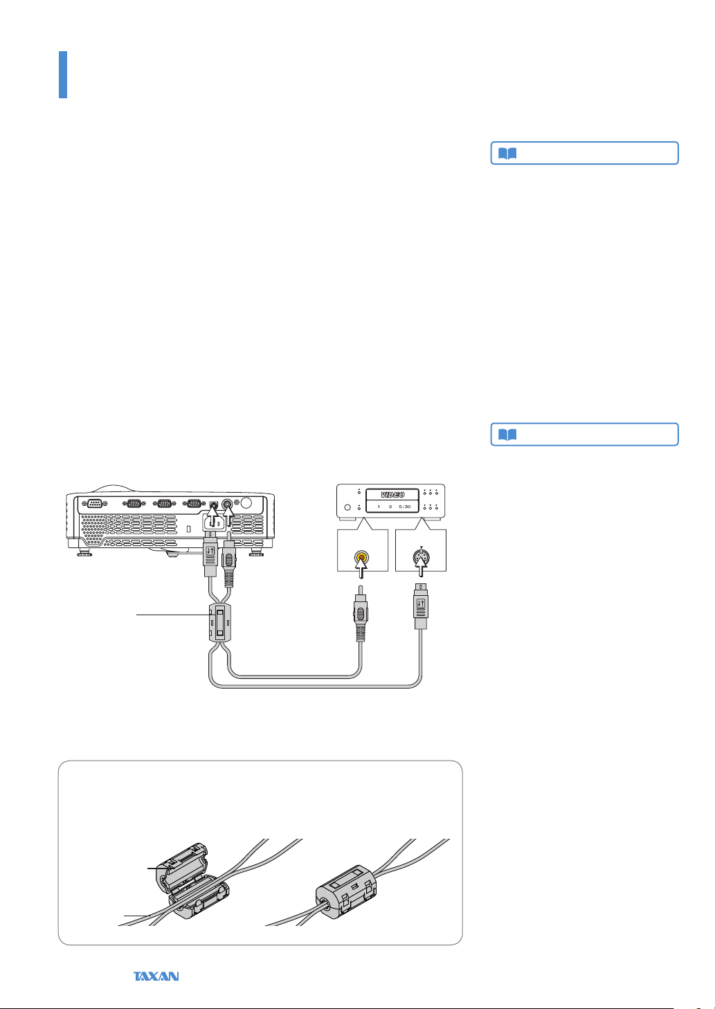
Connections with Typical Video Equipment
This product can project the video from a wide variety of video equipment including video decks, television, and video cameras, etc.
Using RCA Jacks
Connect to the projector’s VIDEO IN connector using a commercially-available
•
video cable.
The factory default input setting of the VIDEO IN connector is set to Auto; how-
•
ever, if there is no projection, change the input setting with Advanced Menu ▶
Input ▶ Video. See “Input” for details. See Page E-74.
Using S-Video Connectors
Connect to the projector’s S-VIDEO IN connector using a commercially-available
•
S-video cable.
The factory default input setting of the S-VIDEO IN connector is set to Auto;
•
however, if there is no projection, change the input setting with Advanced
Menu ▶ Input ▶ S-Video. See “Input” for details. See Page E-74.
Video decks, DVD players, document cameras, etc.
VIDEO S-VIDEO
Technical Point
What is a RCA Connector,
and a S-Connector?
Several types of connectors are used as video connectors
including composite video connectors, separate video connectors, and component video connectors.
Composite video connectors are usually called pin jacks or
RCA jacks, and they are mainly included on video decks,
document cameras, etc.
Separate video connec tors are most typically called S-video,
and becau se they take the form of mini DIN 4-pin con nectors, mini DIN 4-pin m ay also be used to describe S-video.
Component video conne ctors are called color-dierence
input connectors. The us ual NTSC (480i) signal connector
that transfers the C color signal wh ich is divided into the B-Y
color-dierence signal Cb (P b), and the R-Y color-dierence
signal Cr (Pr) is described as Y/Cb/Cr. Connectors that can
be used for video f ormats above NTSC may be described as
Y/Pb/Pr.
Technical Point
What is a ferrite core?
These are accessories that are used to reduce the radiated
noise from the interface cables of digital equi pment and
other devices. When a hig h frequen cy current that is the
source of no ise ows in a cable, it will generate a magnetic
eld and noise will be emitted. The ferrite core abso rbs this
and converts it to heat which is radiated. Attaching a ferrite
core will reduce the deterioration of the picture.
Ferrite core
(Supplied item)
Video cable (Commer-
cially-available)
S-Video cable
(Commercially-available)
Attaching the Ferrite Core
Place side-by-side the commercially-available video cable and the S-video
cable as illustrated in the diagram and attach the supplied ferrite core.
Ferrite core
Cable
E-28
Data Projector
Basic Operation
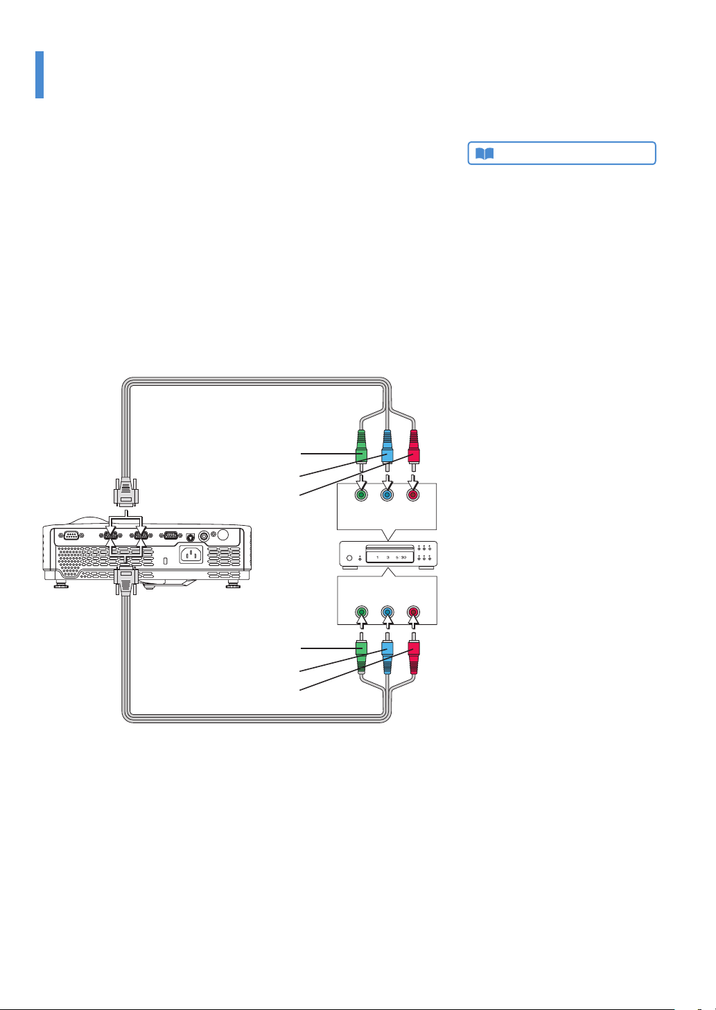
Connecting Personal Computers and Video Equipment
Using YCbCr Connectors or YPbPr Connectors
Use a commercially-available conversion cable to connect with the COMPUTER
•
IN 1/2 connector of the projector.
The factory default input setting of the COMPUTER IN 1/2 connector is set to
•
Auto; however, if there is no projection, change the input setting with Advanced
Menu ▶ Input ▶ Computer 1/2. See “Input” for details. See Page E-74.
When projecting the YCbCr signal or YPbPr signal, if the color of the overall im-
•
age strongly leans toward being greenish or another color, change the setting
under Advanced Menu ▶ Color ▶ Color Space. See “Color Space” for details.
See Page E-72.
Component cable (Commercially-available) (Mini
D-Sub 15-pin/RCA 3-pin)
Green
Blue
Red
Y Cb Cr
Component
Technical Point
What is YCbCr Connector, and
a YPbPr Connector?
Several types of connectors are used as video connectors
including composite video connectors, separate video connectors, and component video connectors.
Composite video connectors are usually called pin jacks or
RCA jacks, and they are mainly included on video decks,
document cameras, etc.
Separate video connec tors are most typically called S-video,
and becau se they take the form of mini DIN 4-pin con nectors, mini DIN 4-pin m ay also be used to describe S-video.
Component video conne ctors are called color-dierence
input connectors. The us ual NTSC (480i) signal connector
that transfers the C color signal wh ich is divided into the B-Y
color-dierence signal Cb (P b), and the R-Y color-dierence
signal Cr (Pr) is described as Y/Cb/Cr. Connectors that can
be used for video f ormats above NTSC may be described as
Y/Pb/Pr.
Green
Blue
Red
Component cable (Commercially-available) (Mini
D-Sub 15-pin/RCA 3-pin)
KG-PS232Xh/232 X | KG-PV131X/131S User’s Manual
Component
Y Pb Pr
E-29
 Loading...