

Page 1

ZoneRanger
User’s Guide
Tavve Software Company
www.tavve.com
Page 2

Copyright
Copyright © 1999–2013 Tavve Software Company
All rights reserved
Printed in USA.
Document Version 5.5 2013
Restricted rights legend
Software and the accompanying documentation are provided to the U.S. Government in a transaction subject
to the Federal Acquisition Regulations with Restricted Rights.
Use, reproduction, or disclosure is subject to restrictions set forth in the commercial license terms and
conditions between Tavve Software Company and the Customer.
Trademarks
CiscoWorks is a registered trademark of Cisco Systems, Inc.
CiscoSecure ACS is a registered trademark of Cisco Systems, Inc.
ZoneRanger is a trademark of Tavve Software Company.
HP NNM is a registered trademark of Hewlett-Packard Company.
Tivoli NetView is a registered trademark of Tivoli Systems and IBM company.
OpenVPN is a trademark of OpenVPN Solutions LLC.
Copyright reference
Copyright © 1999-2003 Intalio Inc. All Rights Reserved.
Copyright ©1999-2013 The Apache Software Foundation. All Rights reserved.
Copyright © 2003-2012 Sun Microsystems, Inc. All Rights Reserved.
V1.2.x enhancements, (c) 2005, Multiplan Consultants Ltd.
Copyright © 2000 Just Objects B.V. <[email protected]>
Copyright © 2000-2004, XDoclet Team. All rights reserved.
Copyright © 1996-2008, The PostgreSQL Global Development Group
Copyright © 1994, The Regents of the University of California
Copyright (C) 1991, 1999 Free Software Foundation, Inc.
Copyright (c) 2000 - 2012 The Legion Of The Bouncy Castle
Copyright (c) 2005-2008 Sam Stephenson
Copyright (c) 2002-2008 Atsuhiko Yamanaka, Jcraft, Inc. All rights reserved.
Copyright (c) 2002-2006, A. Abram White. All rights reserved.
Copyright (c) 2002,2003, Stefan Haustein, Oberhausen, Rhld., Germany.
Copyright (c) 2000, 2009 OSGi Alliance.
Third-party software from the following may be included with your product and is subject to the software
license agreement:
Copyright 1998 Carnegie Mellon University. All rights reserved. The name of the University may not be
used to endorse or promote products derived from this software without specific prior written
permission.
ZoneRanger 5.5 User's Guide
2
Page 3

ZoneRanger 5.5 User's Guide
3
Page 4

Preface
About ZoneRanger
The ZoneRanger appliance provides enterprises with a mechanism for extending the reach of
management applications into firewall-protected networks. ZoneRanger, working together with the
Ranger Gateway software component, serves as a proxy firewall for management traffic,
simultaneously enabling the flow of management traffic between applications and devices, and
inspecting/filtering the traffic in order to mitigate security risks.
ZoneRanger has been designed for demilitarized zones (DMZs), which are the most common form
of firewall-protected network, but can also be used in any situation where firewalls prevent the
normal flow of management protocol traffic.
About this Guide
This guide provides detailed information intended to help users successfully deploy, configure and
operate ZoneRangers within their networks. Topics covered include:
• The ZoneRanger architecture
• Deployment arrangements and options for ZoneRanger and Ranger Gateway
• Foundational concepts and mechanisms required to understand, install, configure, and
operate ZoneRangers and Ranger Gateways
• Proxy and management services provided by ZoneRanger
• ZoneRanger and Ranger Gateway user interfaces
Audience
This guide is intended for persons with a good understanding of network protocols and the
management of networks in general.
Technical Support
Technical assistance is available when you purchase a support contract.
Support covers the ZoneRanger device, the Ranger Gateway software, and the technical
documentation. Please have the ZoneRanger serial number located on the back of the device ready
before calling Tavve technical support.
You can contact Tavve technical support at:
• E-mail:[email protected]
• Telephone:+1 919-654-1235
• Fax: +1 919-380-7147
ZoneRanger 5.5 User's Guide
4
Page 5

Document Organization
This guide is divided into six sections:
• Part I, ZoneRanger and Ranger Gateway Overview, describes the architecture of the
ZoneRanger and Ranger Gateway within a network environment. This section provides the
reader with a framework for how the ZoneRanger and Ranger Gateway are deployed and
operate within the enterprise.
• Part II, ZoneRanger Concepts, describes the high level concepts employed by the
ZoneRanger and Ranger Gateway. Understanding of ZoneRanger and Ranger Gateway
concepts is a necessary prerequisite for the rest of this guide.
• Part III, ZoneRanger Services, describes the proxy and management services provided by
ZoneRanger and Ranger Gateway. The functionality of each service is described in detail,
along with associated deployment and configuration options.
• Part IV, ZoneRanger User Interfaces, provides reference documentation for the various
user interfaces used to configure and operate the ZoneRanger and the Ranger Gateway.
• Part V, ZoneRanger Applications, describes separately licensed ZoneRanger feature sets
for specific management applications.
• Appendices, provides additional information on miscellaneous topics associated with
ZoneRanger and Ranger Gateway.
ZoneRanger 5.5 User's Guide
5
Page 6

Table of Contents
Preface ...........................................................................................................................................................................4
Part I. ZoneRanger and Ranger Gateway Overview....................................................................................................8
Chapter 1: Zone Ranger and Ranger Gateway Architecture....................................................................................8
Part II. ZoneRanger Concepts.....................................................................................................................................13
Chapter 2: Address Patterns.....................................................................................................................................15
Chapter 3: Address Transforms...............................................................................................................................16
Chapter 4: Audit.......................................................................................................................................................18
Chapter 5: Backups/Profiles....................................................................................................................................20
Chapter 6: Destination Groups................................................................................................................................22
Chapter 7: Device Groups.......................................................................................................................................23
Chapter 8: GVI/RGVI..............................................................................................................................................25
Chapter 9: Joining....................................................................................................................................................32
Chapter 10: Licensing..............................................................................................................................................34
Chapter 11: Managed Nodes...................................................................................................................................35
Chapter 12: Node Groups........................................................................................................................................36
Chapter 13: Pooling/Redundancy/VIP/Grouping...................................................................................................37
Chapter 14: Proxy Access Control..........................................................................................................................41
Chapter 15: Proxy Caching.....................................................................................................................................46
Chapter 16: Proxy Map............................................................................................................................................48
Chapter 17: Server Groups......................................................................................................................................54
Chapter 18: Whitelist...............................................................................................................................................57
Part III. ZoneRanger Services.....................................................................................................................................58
Chapter 19: Discovery.............................................................................................................................................58
Chapter 20: Forwarding...........................................................................................................................................61
Chapter 21: FTP Proxy............................................................................................................................................65
Chapter 22: HTTP/HTTPS Proxy...........................................................................................................................67
Chapter 23: ICMP Proxy.........................................................................................................................................73
Chapter 24: NTP Proxy............................................................................................................................................74
Chapter 25: Polling..................................................................................................................................................77
Chapter 26: Root Cause...........................................................................................................................................79
Chapter 27: SNMP Proxy........................................................................................................................................80
Chapter 28: TCP Proxy............................................................................................................................................91
Chapter 29: Telnet/SSH Proxy................................................................................................................................93
Chapter 30: TACACS+/RADIUS Proxy...............................................................................................................102
Chapter 31: TFTP Proxy........................................................................................................................................108
Chapter 32: Traffic Monitoring.............................................................................................................................110
Chapter 33: Whitelisting........................................................................................................................................111
Part IV. ZoneRanger and Ranger Gateway Interfaces..............................................................................................112
Chapter 34: ZoneRanger Web Interface................................................................................................................113
Chapter 35: Ranger Gateway Viewer....................................................................................................................208
Chapter 36: ZoneRanger Text Interface................................................................................................................240
Chapter 37: Ranger Gateway Command Interface...............................................................................................291
Part V. ZoneRanger Applications..............................................................................................................................340
Chapter 38: HP OM...............................................................................................................................................341
Chapter 39: Web File.............................................................................................................................................347
Appendices.................................................................................................................................................................353
A. SNMP Agent.....................................................................................................................................................353
B. ZoneRanger and Ranger Gateway Traps.........................................................................................................360
C. SOCKS..............................................................................................................................................................365
D. IP Address Aliasing...........................................................................................................................................367
ZoneRanger 5.5 User's Guide
6
Page 7

E. SSL Communications between ZoneRanger and Ranger Gateway................................................................370
F. Accessing ZoneRanger Though the Ranger Gateway......................................................................................372
G. ZoneRanger Technician Access........................................................................................................................374
H. Installation.........................................................................................................................................................375
I. Installing Ranger Gateway in Solaris 10 Zones................................................................................................377
J. RGVI Client Installation and Configuration.....................................................................................................378
ZoneRanger 5.5 User's Guide
7
Page 8
Part I. ZoneRanger and Ranger Gateway Overview
Chapter 1: Zone Ranger and Ranger Gateway Architecture
Introduction and Deployment Architecture
ZoneRanger is a hardware appliance that provides enterprises with a mechanism for extending the
reach of management applications into firewall-protected networks. ZoneRanger, working together
with the Ranger Gateway software component, serves as a proxy firewall for management traffic,
simultaneously enabling the flow of management traffic between applications and devices, and
inspecting/filtering the traffic in order to mitigate security risks.
ZoneRangers are typically installed in a network zones, such as a DMZ, where there are devices to
be managed that management applications are unable to reach due to firewall-based network
partitioning. The Ranger Gateway software component is typically installed on the same server as
the management application, and acts as the interface between the management application and one
or more ZoneRangers. Ranger Gateway functions as a transparent proxy, intercepting and relaying
management protocol traffic addressed for managed devices, so that the management application
can remain unaware that the Ranger Gateway and ZoneRanger are being used. As a result,
ZoneRanger and Ranger Gateway can be used with a wide variety of management applications.
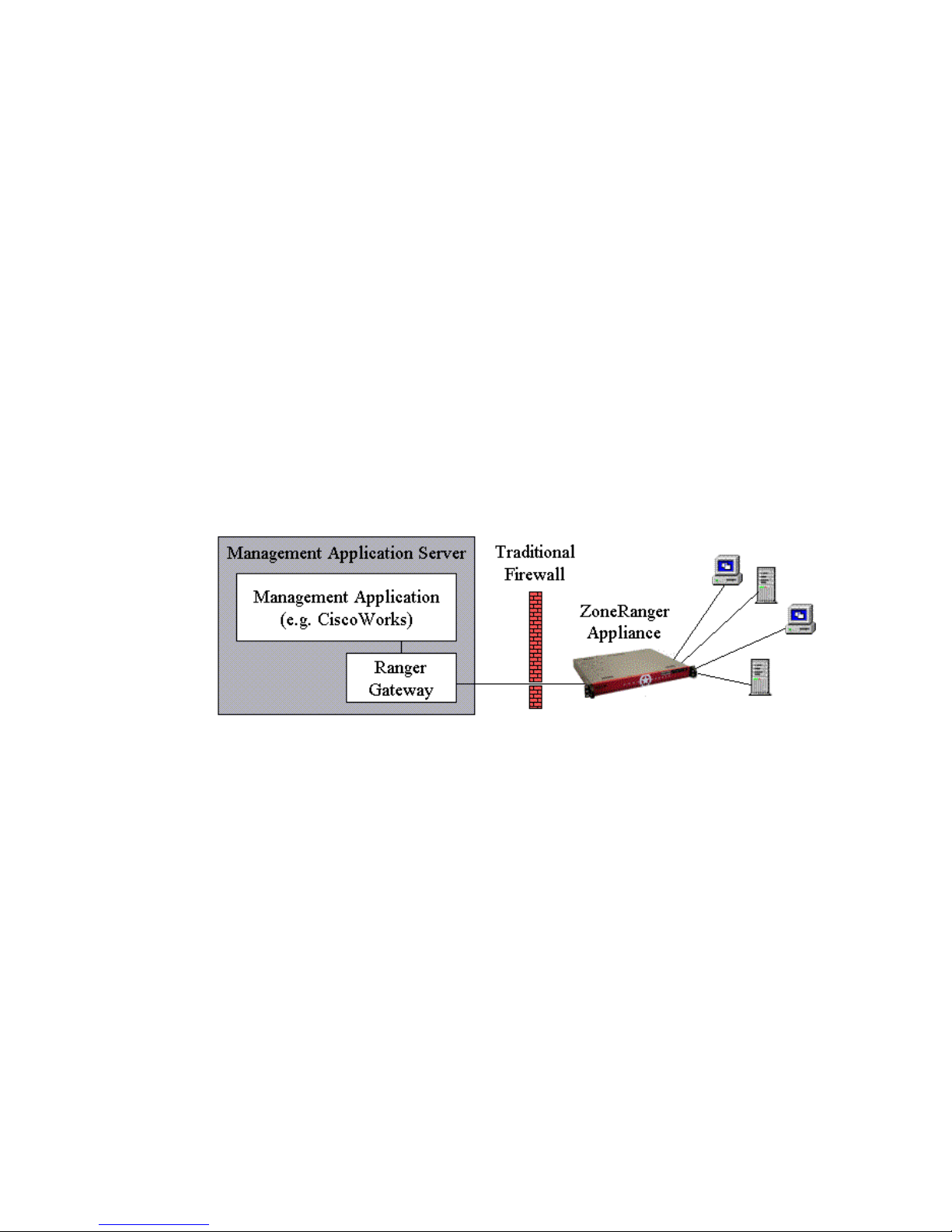
A simple ZoneRanger configuration is illustrated in the following figure.
Figure 1-1. Simple ZoneRanger configuration
Note that the Ranger Gateway software is installed on the same server as the management
application (e.g. CiscoWorks), and that the ZoneRanger is installed in the remote network alongside
the managed devices. The Ranger Gateway and ZoneRanger communicate using a single SSLencrypted TCP connection. All management protocol traffic being proxied through the ZoneRanger
is multiplexed over this single connection, resulting in a dramatic reduction in firewall rules and
associated configuration effort.
ZoneRanger 5.5 User's Guide
8
Page 9
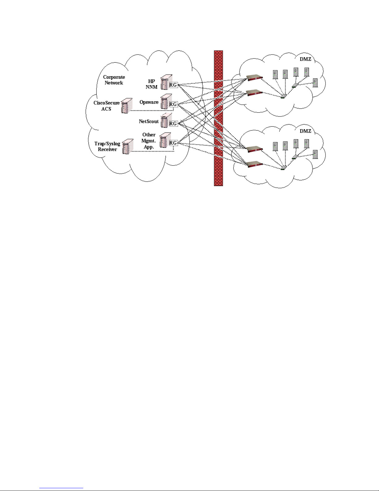
The following figure shows a more advanced ZoneRanger deployment scenario.
Figure 1-2. Advanced ZoneRanger configuration
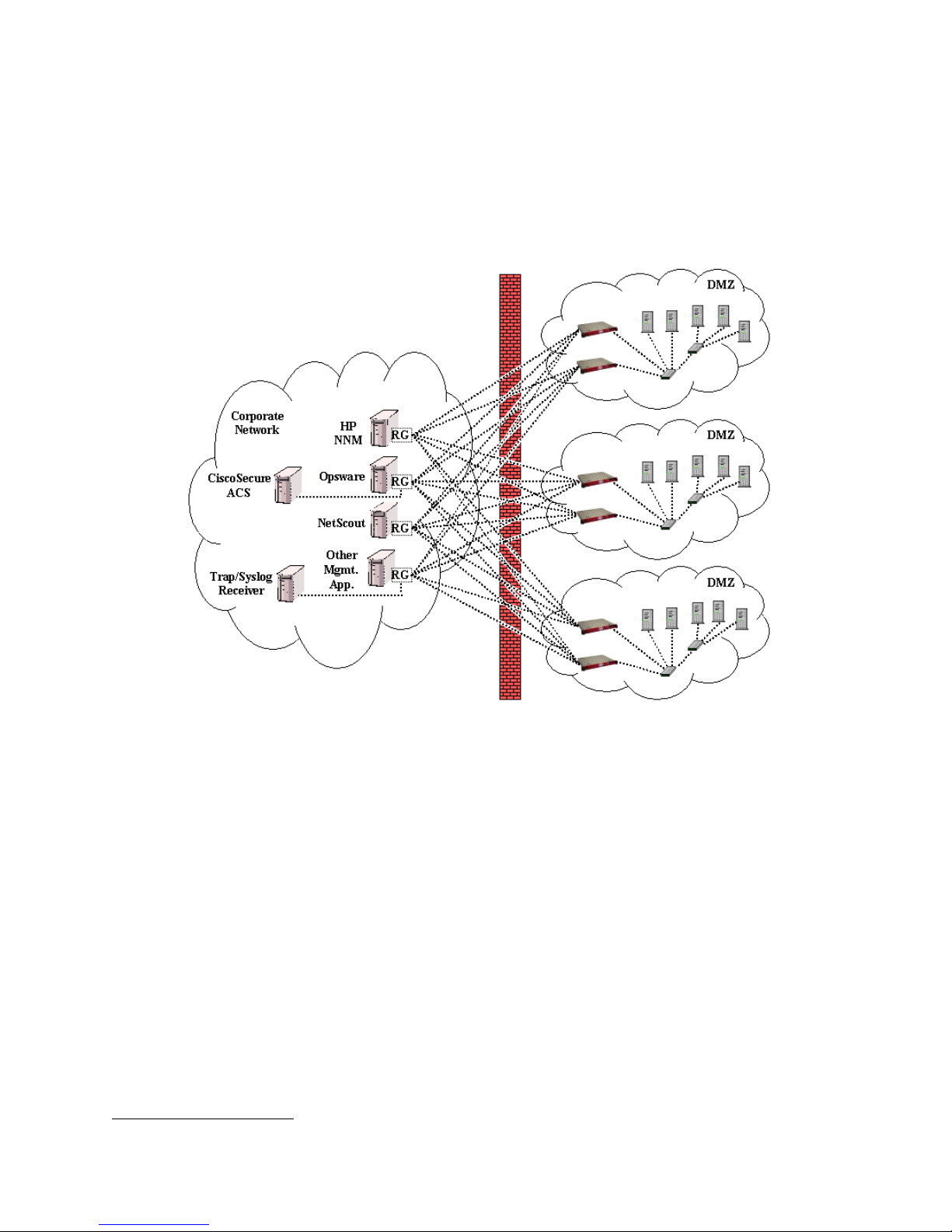
In this scenario there are multiple remote networks to be managed (i.e. multiple DMZ’s), and
multiple management applications. A redundant pair of ZoneRangers is installed in each DMZ, and
instances of the Ranger Gateway (RG) software have been installed on the majority of the
management application servers. An SSL-encrypted TCP connection is maintained between each
Ranger Gateway instance and each ZoneRanger, so that each management application is able to
reach all of the DMZ devices that need to be managed. As a result, there is a many-to-many
relationship between Ranger Gateways and ZoneRangers: each Ranger Gateway instance can be
joined to multiple ZoneRangers and each ZoneRanger can be joined to multiple Ranger Gateways.
The figure also shows two management application servers, one with CiscoSecure ACS and one
with a Trap/Syslog Receiver, that do not have the Ranger Gateway software installed, but instead
interact with the ZoneRangers using Ranger Gateway software installed on another server.
Depending on the nature of the management application, the management protocols being used, and
the server hardware involved, this simplified approach may be advantageous in some situations. In
most cases, however, installing the Ranger Gateway on the same server as the management
application is the preferred approach.
Ranger Gateway software can be installed on any of the various hardware platforms that support the
following operating systems:
• Centos 5.2 or later
• Red Hat Enterprise Linux version 4.0 or higher
• Solaris 2.8 or higher
• SuSE Linux version 11.1 or higher
• Windows XP, Server 2000, Server 2003, 2008 Server, 2008 Server R2
ZoneRanger Services
The primary function of the ZoneRanger is to act as an application-layer proxy firewall for the
protocols most typically used by management applications. ZoneRanger provides proxy services
covering a variety of protocol scenarios:
ZoneRanger 5.5 User's Guide
9
Page 10

• Request/response protocols, where the requests are originated by the management
application:
─ ICMP
─ SNMP
• Request/response protocols, where the requests are originated by the managed devices:
─ TACACS+
─ RADIUS
─ NTP
─ Generic TCP
• Session-oriented protocols, where the sessions are initiated by the management
applications:
─ SSH
─ HTTPS
• Event/notification protocols, where events are generated by managed devices and are
filtered and forwarded to management applications:
─ SNMP
─ Syslog
─ NetFlow
─ sFlow
─ Generic UDP
• File transfer protocols, where the transfers are initiated by the management applications:
─ FTP
─ TFTP
1
ZoneRanger’s proxy services are transparent, in that management applications are not specifically
aware that the Ranger Gateway and ZoneRanger are being used, and do not need to be configured in
a special way in order to incorporate the use of the proxy. This approach simplifies management
application configuration, and enables ZoneRanger and Ranger Gateway to be used with a wide
variety of management applications.
In addition to its role as a management proxy firewall, ZoneRanger can also be configured to act as
a remote management station, performing network discovery, IP, SNMP, and TCP polling, and root
cause analysis. As a result, users have the option of having their management applications poll their
managed devices, with the ZoneRanger acting as a proxy firewall for the polling traffic, or having
the ZoneRanger poll the managed devices, and forward status traps to their management
applications.
User Interfaces
Each ZoneRanger and Ranger Gateway instance can be configured and administered using a textbased, command-line style user interface, or a graphical user interface. The user interfaces for
ZoneRanger and Ranger Gateway are described further in the following sections.
1
ZoneRanger also provides limited support for TFTP transfers initiated by managed devices.
ZoneRanger 5.5 User's Guide
10
Page 11

ZoneRanger User Interfaces
ZoneRanger provides two primary user interfaces:
• A web based interface that can be accessed directly via HTTP on TCP port 80 or HTTPS on
TCP port 443, or via proxy through a joined Ranger Gateway.
• A text-based command-line interface that can be accessed directly via Telnet on TCP port
23, or SSH on TCP port 22, or via proxy through a joined Ranger Gateway.
When accessing the ZoneRanger through either the web interface or text interface, you will need to
authenticate with a login ID and password. ZoneRangers support two authorization levels
(Administrator and Operator) and are shipped with the following initial user configuration:
User Name Password Access Level
admin admin Administration
operator operator Operator
When using the web interface, the administrator authorization level enables access to all
ZoneRanger configuration and operation menus. Users having operator access are able to view the
ZoneRanger status, and information regarding managed devices and associated protocol traffic, but
are not allowed to configure the ZoneRanger or initiate administrative actions. For security, users
are automatically logged out of the ZoneRanger web interface after 30 minutes of inactivity.
Reference documentation for the ZoneRanger web interface is provided in Chapter 30.
The text interface requires administrator authorization privileges. Users with operator authorization
are not permitted to access the ZoneRanger text interface. Reference documentation for the
ZoneRanger text interface is provided in Chapter 32.
Ranger Gateway User Interfaces
Ranger Gateway provides two user interfaces:
1. A GUI-based client application, called the Ranger Gateway Viewer.
2. A text-based command-line interface, consisting of a set of commands that can be executed
from an operating system shell on the server where the Ranger Gateway has been installed.
The Ranger Gateway command interface is implemented as a set of executable commands, installed
in a bin directory. In the case of Solaris and Linux, this directory also includes a command to start
the Ranger Gateway Viewer application. The location of this bin directory is dependent on the
operating system:
Operating System Directory
Linux install_dir/gateway/bin
Solaris install_dir/gateway/bin
Windows install_dir\bin
where <install_dir> is the directory where the Ranger Gateway software was installed.
To start the Ranger Gateway Viewer on a Solaris or Linux system, run the RangerGateway
command from an operating system shell. To start the Ranger Gateway Viewer on a Windows
system, select Programs > Tavve > Ranger Gateway Viewer from the Start menu. Reference
documentation for the Ranger Gateway Viewer is provided in Chapter 33.
All of the commands which comprise the Ranger Gateway command interface are executed from an
operating system shell. You can execute any command with a -? argument to display the usage
information for that command, as illustrated in the following figure.
ZoneRanger 5.5 User's Guide
11
Page 12
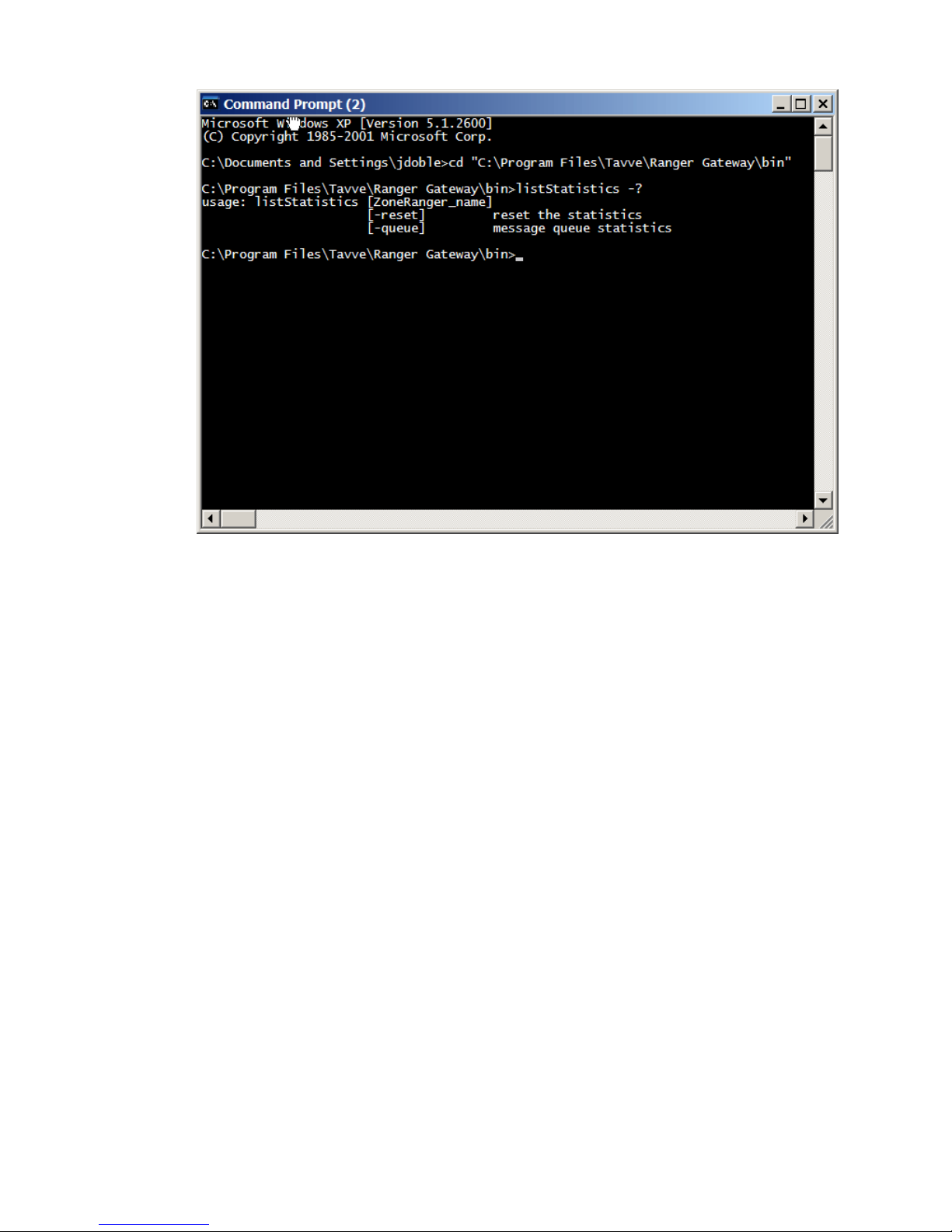
Figure 1-3. Ranger Gateway Command example
Reference documentation for the Ranger Gateway command interface is provided in Chapter 36.
ZoneRanger 5.5 User's Guide
12
Page 13

Part II. ZoneRanger Concepts
This section introduces and describes foundational concepts and mechanisms that are important for
ZoneRanger users to understand, so that they can properly configure and administer their ZoneRangers, and
obtain maximum value from their ZoneRanger deployments. Later chapters will build on these concepts and
mechanisms and will assume that the reader is reasonably familiar with the content of this section.
The following concepts and mechanisms are discussed:
• Address Patterns – IP address or hostname values that contain wild card characters or range
descriptions and thus can describe a range of IP addresses or hostnames.
• Address Transforms – Rules that specify how to transform IP addresses or hostnames to new values
(e.g. to accommodate NAT).
• Audit – The automated process whereby Ranger Gateway and ZoneRanger perform periodic self-
checks, and, where necessary, perform corrective actions.
• Backups/Profiles – Mechanisms for saving and restoring all or part of a ZoneRanger and Ranger
Gateway configuration.
• Destination Groups – ZoneRanger mechanism for defined named groups of Ranger Gateways and
UDP packet destinations to be applied to forwarding rules as a means to create and manage fewer
rules.
• Device Groups – Ranger Gateway mechanism for defining named groups of managed devices, and
using these named groups in a variety of configuration rules.
• Node Groups – ZoneRanger mechanism for defining named groups of IP address patterns, and
using these node groups in a variety of configuration rules particularly forwarding and proxy rules.
• Pooling/Redundancy/VIP/Grouping – Mechanisms for providing high availability and/or load-
balancing ZoneRanger deployments.
• Gateway Virtual Interface (GVI) and Remote Gateway Virtual Interface (RGVI) – Mechanisms
whereby the Ranger Gateway intercepts requests generated by management applications that are
destined for managed devices, so that these requests can be relayed through a ZoneRanger to the
target devices.
• Joining – The process by which a working association between Ranger Gateway and a ZoneRanger
is established.
• Managed Nodes – Mechanism whereby a ZoneRanger user identifies the set of nodes (e.g. network
devices, servers) to which ZoneRanger proxy and management services will be applied.
• Proxy Access Control – Mechanism whereby the Ranger Gateway identifies the management
protocol to be used for a given destination address, transport protocol, and destination port. Also can
be used to restrict access to proxy services based on source address, destination address, transport
protocol and destination port.
• Proxy Caching – Mechanism for reducing management traffic by saving the results of recent ICMP
and SNMP proxy requests, and, where appropriate, returning saved values instead of passing the
request along to the managed device.
• Proxy Map – Mechanism whereby the Ranger Gateway selects an appropriate ZoneRanger to proxy
a management protocol transaction, based on configured rules.
• Server Groups – ZoneRanger mechanism for defining named groups of TACACS+/RADIUS
servers and associated settings.
ZoneRanger 5.5 User's Guide
13
Page 14

• Whitelist – ZoneRanger mechanism to define a specific list of devices from which only those
devices will the ZoneRanger either receive data or send data.
Each of these concepts and mechanisms are described in further detail in the following chapters.
ZoneRanger 5.5 User's Guide
14
Page 15

Chapter 2: Address Patterns
An address pattern is an IP address or hostname value that contains wild card characters or range
descriptions and thus can be used to describe a range of IP addresses or hostnames. Address patterns are
commonly used in Ranger Gateway and ZoneRanger commands and configuration tables, in order to
provide a concise mechanism for specifying a set of related addresses.
For example, all of the IP addresses in the 64.1.25.0/24 subnet, can be described using the
following address pattern:
62.1.25.*
The * wildcard character can appear in any part of the address. More specific ranges can also be
specified, such as:
64.[1-2].25.[1-10]
Wildcard characters can also be used with host names. For example:
*.company.com
or
*.*.company.com
Wildcard and non-wildcard characters cannot be combined within a part of the address. For example, the
following address patterns would not be allowed:
abc*.company.com
64.1.25.1[6-8]
In order for a hostname pattern to match a given address, the number of address parts must match. For
example, the hostname server1.company.com matches the pattern *.company.com, but the
hostname server1.payroll.company.com does not.
ZoneRanger 5.5 User's Guide
15
Page 16

Chapter 3: Address Transforms
An address transform is a simple rule that specifies how to take a given IP address or hostname value,
and transform it to a new value. Address transforms are used by the Proxy Map service in the Ranger
Gateway in order to accommodate static NAT configurations, where the address for a managed device as
specified by a management application is different from the actual address of the managed device.
Address transforms, in this case, are used to convert the device address as specified by the management
application into the real address that the ZoneRanger will use to communicate with the managed device.
For example, the following address transform indicates that the first three parts of the resulting address
should be 192.168.1, and the wild card character in the last part of the transform indicates that that
the last part of the resulting address should be copied from the original address.
192.168.1.*
The following table illustrates the addresses that would result from applying a variety of simple address
transforms to a number of input addresses:
Original Address Address Transform Resulting Address
127.0.0.3 192.168.1.* 192.168.1.3
64.2.37.4 192.168.1.* 192.168.1.4
64.2.37.55 10.1.*.* 10.1.37.55
192.168.2.10 10.1.*.* 10.1.2.10
Address transforms can also perform simple computations. For example, the following address
transform indicates that the first three parts of the resulting address should be 192.168.1, and the *+2
expression in the last part of the transform indicates that that the last part of the resulting address should
be calculated by taking the last part of the original address and adding 2.
192.168.1.*+2
The following table illustrates the addresses that would result from applying a variety of address
transforms to a number of input addresses:
Original Address Address Transform Resulting Address
127.0.0.3 192.168.1.*+2 192.168.1.5
64.2.37.4 192.168.1.*+2 192.168.1.6
64.2.37.25 10.1.*-2.*+2 10.1.35.27
192.168.3.200 10.1.*-2.*+2 10.1.1.202
192.168.3.254 10.1.*-2.*+10 10.1.1.8
Note that + and – are the only operations allowed, and all arithmetic is modulo 256.
Address transforms can also be used with host names. For example, the following address transform
indicates that the last two parts of the resulting hostname should be dmz1.com, and that the first part of
the hostname should be copied from the original hostname.
*.dmz1.com
The number of parts in the original hostname does not need to exactly match the number of parts in the
address transform. For example, the following table illustrates the addresses that would result from
applying the address transform *.dmz1.company.com to a variety of input hostnames:
ZoneRanger 5.5 User's Guide
16
Page 17

Original Address Address Transform Resulting Address
host1.company.com *.dmz1.company.com host1.dmz1.company.com
host2.company.com host2.dmz1.company.com
host3.net1.company.com host3.dmz1.company.com
host4.net2.branch1.company.com host4.dmz1.company.com
Note that wildcard characters in address transforms always refer to the corresponding part in the input
address or hostname, as counted from left to right.
Wildcard and non-wildcard characters cannot be combined within a part of an address transform. For
example, the following address transform is invalid:
dmz*.company.com
Examples showing how address transforms can be used when dealing with NAT scenarios, or when
managing network zones with overlapping address spaces, are provided in Chapter 16.
ZoneRanger 5.5 User's Guide
17
Page 18

Chapter 4: Audit
In order to provide a high level of reliability, the ZoneRanger appliance and the Ranger Gateway
software both incorporate a periodic self-audit process. The audit process in each case runs on a fiveminute interval, performing a series of pre-configured tests, verifying that services are configured
correctly, that components are able to communicate as required, and that the software is operating
properly. In the normal case, where no problems are detected, the audit will simply terminate, and
reschedule itself to run again five minutes later. If any problems are detected, the audit process will
inform the user in a variety of ways:
• The ZoneRanger web interface can be used to view the results of the most recent audit for that
ZoneRanger (on the Information section of the ZoneRanger dashboard, and on the View >
System Audit page).
• The Ranger Gateway Viewer can be used to view the results of the most recent Ranger Gateway
audit, and the results of the most recent audits for any joined ZoneRangers.
• The auditResult command on the Ranger Gateway can be used to view the results of the
most recent Ranger Gateway audit, and the results of the most recent audits for any joined
ZoneRangers.
• The audit process can be configured to send an SNMP trap whenever a problem is detected.
• The audit process can be configured to send a Syslog message whenever a problem is detected.
When audit results are presented to the user, a description of the problem being reported is provided,
along with an assessment of the severity of the problem. Two severity categories are supported:
• Major: The problem that has been detected is significant and may affect the ability of the
ZoneRanger or Ranger Gateway to provide necessary services. Corrective action should be
taken immediately.
• Minor: The problem that has been detected may impair the operation of one or more services,
but does not necessarily require immediate attention.
In addition to informing the user, the audit process may, where appropriate, automatically perform one
or more corrective actions in an attempt to resolve the problem that has been detected. The ability to
automatically correct a problem fundamentally depends on the nature of the problem. For example, if a
ZoneRanger is unable to communicate with a Ranger Gateway, or if a service has been configured
incorrectly, the audit process will notify the user, as described above, but no automatic corrective action
will be taken. If an internal software error has been detected, on the other hand, the audit process will
perform an escalating series of corrective actions, typically beginning with restarting the affected
internal service, and potentially restarting the entire software application, or, in the case of ZoneRanger,
rebooting the appliance, if a problem persists across multiple audit cycles.
It should be noted that the Ranger Gateway Viewer, the ZoneRanger web interface, and the
listAuditResults command all display the results of the most recent audit. As a result,
when a problem detected by the audit process is corrected, that problem will remain in the list of
detected problems until the next audit cycle. When the next audit cycle completes, the problem should
no longer be listed, provided that the corrective action was successful.
ZoneRanger 5.5 User's Guide
18
Page 19

In addition to the primary audit process, as described above, the ZoneRanger appliance also includes a
secondary audit, which runs every thirty minutes. The goal of the secondary audit is to verify that the
primary audit is doing its job. If the secondary audit determines that the primary audit is no longer
functioning properly, the ZoneRanger appliance will be automatically rebooted. This two-layer audit
approach helps to ensure that ZoneRanger will continue to operate reliably, even when unexpected
software problems occur. Note that the Ranger Gateway does not include a comparable secondary audit,
because the Ranger Gateway software is typically installed on the same server as one or more
management applications, and users will typically prefer to keep these applications running, even if
Ranger Gateway problems are detected.
ZoneRanger 5.5 User's Guide
19
Page 20

Chapter 5: Backups/Profiles
ZoneRanger provides two mechanisms for managing sets of configuration information: backups and
profiles. Backups and profiles are similar in that in each case, a set of configuration information for a
ZoneRanger is gathered and saved in a file that can be restored to the same ZoneRanger, or applied to a
different ZoneRanger. The primary difference between backups and profiles is that backups contain the
content of the ZoneRanger’s database of discovered devices, as well as any polling/management
configuration associated with those devices that is also stored in the database, while profiles do not.
ZoneRanger Profiles
Profiles are intended to be used as a form of configuration template, so that a ZoneRanger configuration
can be developed, captured, and easily replicated across a set of ZoneRangers that may be installed in
different network regions, and be managing different sets of devices. Backups, on the other hand, can be
used to roll back a given ZoneRanger’s configuration to a previous state, to auto-configure a new
ZoneRanger that is being added to an existing pool, or to replace an existing ZoneRanger that may have
failed or is being redeployed to another location.
Profiles are created (a.k.a. saved) using the ZoneRanger web interface, from the Administration >
Profiles page. The user has two options with regards to the location(s) where the profile file will be
stored:
• The profile can be saved on the ZoneRanger only.
• The profile can be saved on the ZoneRanger, and also copied to a joined Ranger Gateway.
When loading (i.e. applying) a profile, the user can choose to load any profile stored on that
ZoneRanger, or stored on any joined Ranger Gateway. Note that a profile can only be loaded on a
ZoneRanger that is at the same software version as the ZoneRanger that created the profile. The
ZoneRanger web interface can also be used to delete profiles from the ZoneRanger or any joined Ranger
Gateway.
ZoneRanger Backups
Backups can be created using the ZoneRanger web interface, from the Administration >
Backup/Restore page, or by executing the Ranger Gateway backup command. When creating a
backup from the web interface, the user has two options with regards to the location(s) where the backup
file will be stored:
• The backup can be saved on the ZoneRanger only.
• The backup can be saved on the ZoneRanger, and also copied to a joined Ranger Gateway.
When creating a backup using the Ranger Gateway backup command, the backup will always be saved
on the ZoneRanger, and copied to the Ranger Gateway where the command was executed. Note that the
backup command is primarily intended to allow users to perform automated periodic backups. For
example, if the Ranger Gateway is installed on a Solaris or Linux operating system, a cron job can be
configured to run this command at scheduled times. In a similar manner, the Scheduled Tasks
mechanism can be used to automate backups on a Windows operating systems. Backups are stored in
the Ranger Gateway store/zr/backup directory.
Backups can only be restored from the ZoneRanger web interface. When restoring from a backup, the
user can choose any backup file stored on that ZoneRanger, or stored on any joined Ranger Gateway.
Note that a backup file can only be loaded on a ZoneRanger that is at the same software version, model
number (e.g. ZR-50, ZR-200, ZR-500, ZR-SPX, or ZR-MSP) and hardware version as the ZoneRanger
that created the backup file. The ZoneRanger web interface can also be used to delete backup files from
the ZoneRanger or any joined Ranger Gateway.
ZoneRanger 5.5 User's Guide
20
Page 21

It should be noted that there is a small amount of ZoneRanger configuration information that is currently
not included in a backup and must always be configured manually:
• IP interface configuration (i.e. which interfaces are enabled, and their associated IP addresses
and network masks).
• Joining passcode.
• SNMP agent configuration (e.g.. sysContact and sysLocation)
Ranger Gateway Backups
Backups of the Ranger Gateway configuration can be created and restored using the Ranger Gateway
rgBackup command. Only backups of the same Ranger Gateway version may be restored. By default,
Ranger Gateway backups are located in the <install_dir>/backups directory. However, the [ -d
directory] option may be used to create or restore Ranger Gateway backups from an alternate directory.
Note, when a Ranger Gateway backup is restored, the Ranger Gateway software will be restarted.
ZoneRanger 5.5 User's Guide
21
Page 22

Chapter 6: Destination Groups
A destination group is a named set of rules which can be used in forwarding rules to define where a
UDP datagram will be forwarded. Each individual rule in a destination group is comprised of a Ranger
Gateway or Data Diode and the ultimate destination of the UDP datagram. Destination groups provide a
mechanism to improve the organization of forwarding rules by grouping all rules that are configured
with the same Ranger Gateways and final destinations together. This allows for the creation and
management of fewer Forwarding Rules.
For example, if a ZoneRanger was joined to three Ranger Gateways (RG1, RG2, RG3) that were used to
forward syslog messages to three management applications (appl, app2, app3). If there were also five
specific syslog filters configured on the ZoneRanger to process syslog messages and forward those
messages to each of the management applications, that would require the creation of 15 forwarding
rules.
Forwarding Rules
– RG1 app1 syslog rule 1
– RG1 app1 syslog rule 2
– RG1 app1 syslog rule 3
– RG1 app1 syslog rule 4
– RG1 app1 syslog rule 5
– RG2 app2 syslog rule 1
– RG2 app2 syslog rule 2
– ...
– RG3 app3 syslog rule 5
With destination groups, a single destination group (DG1) could be created with rules for each Ranger
Gateway and management application as the destination. Then only 5 forwarding rules would need to
be created for the syslog messages.
Destination Group (DG1)
– RG1 app1
– RG2 app2
– RG3 app3
Forwarding Rules
– DG1 syslog rule 1
– DG1 syslog rule 2
– DG1 syslog rule 3
– DG1 syslog rule 4
– DG1 syslog rule 5
ZoneRanger 5.5 User's Guide
22
Page 23
Chapter 7: Device Groups
A device group is a named set of IP addresses, or address patterns, defined using the deviceGroup
command on the Ranger Gateway, or using the Ranger Gateway Viewer. Device groups are similar to
address patterns in that they provide a concise mechanism for referring to a collection of devices in
configuration rules. The advantage of device groups is that they can refer to an arbitrary collection of
devices with disjoint addresses, as opposed to address ranges and wild cards which can only refer to
contiguous IP address spaces. This is useful when you need to apply configuration settings to devices of
a particular type (e.g. routers), where it is unlikely that the addresses of these devices will happen to fall
within a contiguous range.
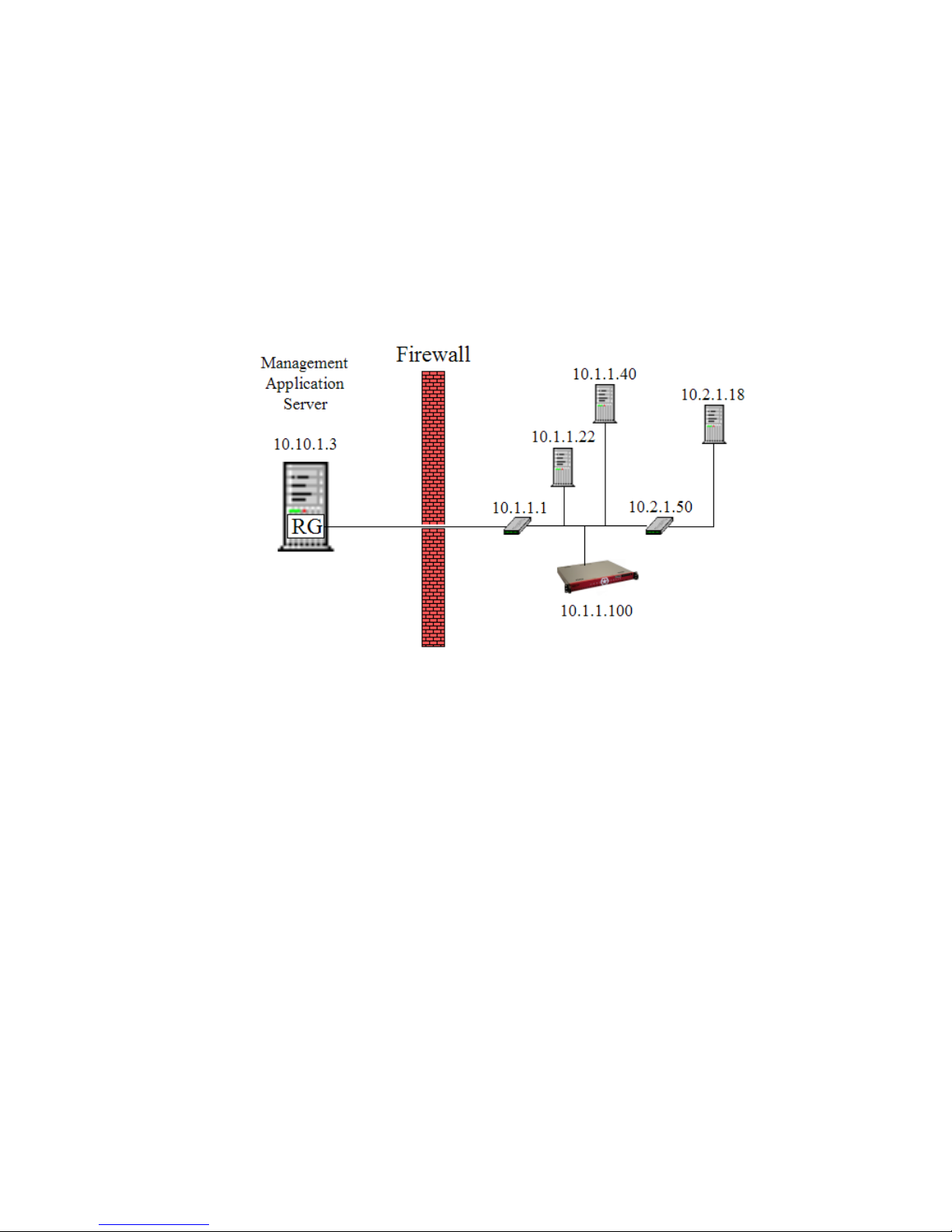
For example, consider the following network:
Figure 7-1. Device Group configuration
The managed network in the figure contains two routers (10.1.1.1, and 10.2.1.50), three servers
(10.1.1.22, 10.1.1.40, and 10.2.1.18), and one ZoneRanger (10.1.1.100). In order to facilitate different
configuration settings for different device types, we could define two device groups:
• MyRouters: 10.1.1.1, 10.2.1.50
• MyServers: 10.1.1.22, 10.1.1.40, 10.2.1.18
Device groups can be used to define rules associated with Proxy Access Control (see Chapter 14) and
Proxy Map (see Chapter 16) services on the Ranger Gateway. For example, one of the tables used in
Proxy Access Control consists of rules of the following form:
<src-address> <dest-address> <port-configuration>
The <src-address> and <dest-address> values in these rules can be specified in the form of
specific addresses, address patterns, or device groups. Using the MyRouters and MyServers device
groups defined above, and assuming we have three defined port configurations, unimaginatively named
portConfig-1, portConfig-2, and portConfig-3, we could configure Proxy Access Control
using the following rules:
• *.*.*.* @MyRouters portConfig-1
• *.*.*.* @MyServers portConfig-2
• *.*.*.* 10.1.1.100 portConfig-3
ZoneRanger 5.5 User's Guide
23
Page 24

In addition to user-defined device groups, there are two special device groups that are defined
automatically:
• The Local device group consists of all addresses that are local to the Ranger Gateway server.
• The ZoneRanger device group consists of the IP addresses of all joined ZoneRangers
2
.
Using these device groups, in the network shown above, if we wanted to only allow proxy requests
originating from the Ranger Gateway server, the Proxy Access Control rules above could be rewritten
as:
• @Local @MyRouters portConfig-1
• @Local @MyServers portConfig-2
• @Local @ZoneRanger portConfig-3
Device groups can also contain device groups. For example, we could define a new group called
MyRoutersAndServers as follows:
MyRoutersAndServers: @MyRouters, @MyServers
Once a device group is defined, and configuration settings have been associated with it, those settings
can be applied to a new device by simply adding that device to the group. Similarly, a device that is
included in a configured device group can be reverted back to default settings by simply removing that
device from the group.
2
As a convenience, the ZoneRanger device group also includes any IP addresses that map to a joined
ZoneRanger based on the Proxy Map configuration.
ZoneRanger 5.5 User's Guide
24
Page 25

Chapter 8: GVI/RGVI
In order for the ZoneRanger to proxy management traffic to managed devices, the management traffic
generated by a management application must first be routed to the Ranger Gateway. This can be
accomplished in a variety of ways:
1. Configure the management application to direct management traffic associated with devices
located in firewall-partitioned networks to the Ranger Gateway.
2. Provide a mechanism whereby management traffic destined for devices located in firewallpartitioned networks is intercepted by the Ranger Gateway.
The primary advantage of the latter approach is that the management application can send requests to
devices located in firewall-partitioned networks as if it was communicating with those devices directly.
The fact that the requests are intercepted and processed by the Ranger Gateway is effectively hidden
from the management application. This ability to hide the existence of the proxy from the management
application is referred to as transparent proxy. The preferred mechanisms for supporting transparent
proxy on the Ranger Gateway are the Gateway Virtual Interface (GVI) and the Remote Gateway Virtual
Interface (RGVI). These mechanisms are described in the following sections.
GVI
The GVI mechanism is used when the management application and Ranger Gateway software are
installed on the same server. The internal architecture and operation of the GVI mechanism is illustrated
in the following figure.
Figure 8-1. GVI Architecture
ZoneRanger 5.5 User's Guide
25
Page 26

When the GVI service is enabled, the Ranger Gateway creates a virtual point-to-point interface on the
management application server, and adds one or more static routes to the management application server
so that traffic destined for devices located in firewall-partitioned networks is routed to this virtual
interface (1). The GVI service in the Ranger Gateway, as the creator/owner of the virtual interface,
receives all traffic that is routed to the virtual interface (2). The GVI service consults with the Proxy
Access Control service in the Ranger Gateway to determine if the traffic should be allowed, and to
identify the protocol-specific proxy service (e.g. SNMP proxy, TCP proxy) that should handle the traffic.
If the request is allowed, the GVI service forwards the traffic to the selected proxy service (3). The
proxy service consults the Proxy Map service in the Ranger Gateway in order to identify identify a
ZoneRanger that is able to relay the traffic to the target device, and to translate the target address, if
necessary, and then forwards the traffic to the selected ZoneRanger (4)(5), which in turn, forwards the
traffic to the target DMZ device (6). Where applicable, proxy services may also perform validation and
filtering of the management traffic, as appropriate for the service being used.
The GVI service also includes a route manager that simplifies creation and management of the static
routes that are needed so that management traffic is routed to the virtual interface. The route manager
can be configured with a set of subnets or individual IP addresses that should be routed to the virtual
interface, and will automatically create the associated static routes when the GVI service is enabled, and
will delete these routes when the GVI service is disabled. If the GVI service is enabled and the Ranger
Gateway software is stopped, the route manager will automatically remove any static routes associated
with the virtual interface, and will reconfigure these routes when the Ranger Gateway software is
restarted. As a result, there should be no need to redefine static routes if the management application
server is rebooted, because the virtual interface static routes will be reconfigured when the Ranger
Gateway software is started.
The virtual interface created by the GVI service emulates a point-to-point interface. As such, a local IP
address and a remote IP address must be associated with this interface. By default, the GVI service
configures the virtual interface with the following addresses:
• Local: 192.168.48.1
• Remote: 192.168.48.2
Alternative addresses can be configured if these addresses create a conflict. Please contact Tavve
Support for more information if you need to change these addresses.
In order to route a subnet corresponding to a set of managed devices to the virtual interface, the route
manager creates a static gateway route to the virtual interface’s remote address. For example, in order to
route the 10.1.10.0/255.255.255.0 subnet to the virtual interface, the following route would be
defined:
10.1.10.0 255.255.255.0 192.168.48.2
Before creating a static route for a given subnet, the route manager checks to see if any of the IP
addresses being used to communicate with joined ZoneRangers lie within the subnet being added. In
order to ensure that communication with joined ZoneRangers can continue, the route manager
automatically creates host routes for any such addresses. These host routes override the subnet routes in
the system routing table for the given IP addresses, and effectively ensure that traffic destined for joined
ZoneRangers is routed to the gateway that would have been used in the absence of any virtual interface
routes.
ZoneRanger 5.5 User's Guide
26
Page 27
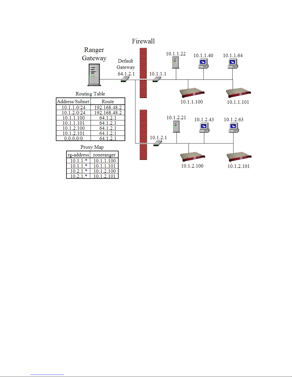
For example, consider the network in the following figure:
Figure 8-2. GVI Example
In the example, a Ranger Gateway is being used to manage two firewall-partitioned networks. Two
ZoneRangers have been deployed into each of these networks. In order to intercept management traffic
destined for these networks, two GVI subnet routes have been configured:
• 10.1.1.0/24
• 10.1.2.0/24
When the GVI service is enabled, the GVI route manager will automatically create static routes
indicating that traffic destined for these subnets should be routed to the GVI interface's remote address
(192.168.48.2). Given that the IP addresses of each of the ZoneRangers lie within these subnets, the GVI
route manager will automatically create host routes for each of the joined ZoneRangers indicating that
traffic destined for the ZoneRanger addresses should be routed via the original default gateway that was
configured for the Ranger Gateway server (64.1.2.1). The figure also shows the original default routing
rule (0.0.0.0/0 → 64.1.2.1), and a simple Proxy Map configuration indicating which ZoneRangers
should be used to proxy traffic for which device addresses.
If the GVI service is enabled, and a request to join to a given ZoneRanger is received by the Ranger
Gateway, the GVI route manager will automatically create a host route for that IP address, where
necessary to ensure that traffic destined for the ZoneRanger will bypass the virtual interface. Host routes
for joined ZoneRangers will automatically be removed from the system routing table if the ZoneRanger
is unjoined, any overlapping virtual interface routes are removed, or the GVI service is disabled.
The GVI service can be controlled and configured using the Ranger Gateway Viewer or the gvi Ranger
Gateway command.
On Windows servers, once the GVI is enabled, run the Windows command ncpa.cpl to display the
current list of network interfaces. Using the Advanced > Advanced Settings... menu item, verify that
the GVI virtual interface is last in the access order for network services.
ZoneRanger 5.5 User's Guide
27
Page 28
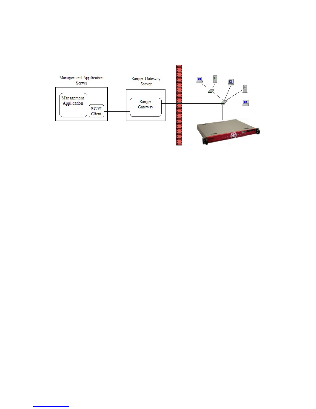
RGVI
The RGVI mechanism is used when the management application and Ranger Gateway software are
installed on different servers, as illustrated in the following figure.
Figure 8-3. RGVI Architecture
The RGVI mechanism makes use of a thin RGVI client, installed on the management application server.
The RGVI client intercepts traffic destined for managed devices, and relays this traffic to the Ranger
Gateway software using a UDP-based communication protocol.
The primary advantages of RGVI are as follows:
• The processor/memory footprint of the RGVI client is considerably less than the Ranger
Gateway software.
• The RGVI client can be installed on some operating systems for which the Ranger Gateway
software is not currently supported.
The internal architecture and operation of the RGVI mechanism is illustrated in the following figure.
ZoneRanger 5.5 User's Guide
28
Page 29
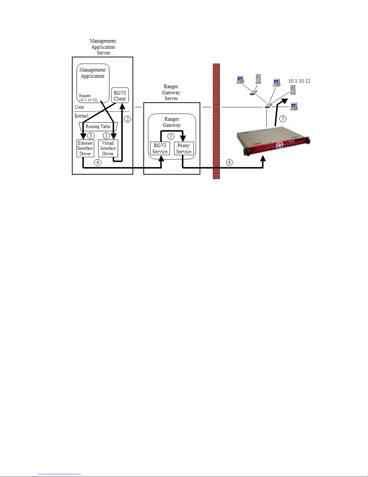
Figure 8-4. RGVI Architecture
The RGVI Client is configured with the addresses of one or more Ranger Gateway servers to which it
can connect in order to provide proxy services. When the RGVI client is initialized on the Management
Application Server, it creates a virtual point-to-point interface which is used to intercept traffic destined
for managed devices, similar to the approach used for GVI, then attempts to connect to one of the
configured Ranger Gateway servers. When the connection to a Ranger Gateway server is established,
the Ranger Gateway will send the RGVI client a list of individual IP addresses and subnets that the
RGVI client should intercept. On receipt of this list, the RGVI client will configure corresponding static
routes on the management application server so that traffic destined for devices located in firewallpartitioned networks is routed to its associated virtual interface (1). The RGVI client, as the
creator/owner of the virtual interface, receives all traffic that is routed to the virtual interface (2), then
relays this traffic to the Ranger Gateway server to which it has connected (3)(4). Within the Ranger
Gateway, this traffic is received by the RGVI service which consults with the Proxy Access Control
service in the Ranger Gateway to determine if the traffic should be allowed, and to identify the protocolspecific proxy service (e.g. SNMP proxy, TCP proxy) that should handle the traffic. If the request is
allowed, the RGVI service forwards the traffic to the selected proxy service (5). The proxy service
consults the Proxy Map service in the Ranger Gateway in order to identify identify a ZoneRanger that is
able to relay the traffic to the target device, and to translate the target address, if necessary, and then
forwards the traffic to the selected ZoneRanger (6), which in turn, forwards the traffic to the target DMZ
device (7). As in the case of GVI, where applicable, proxy services may also perform validation and
filtering of the management traffic, as appropriate for the service being used.
The RGVI mechanism allows a single Ranger Gateway server to support multiple management
application servers, as illustrated in the following figure.
ZoneRanger 5.5 User's Guide
29
Page 30
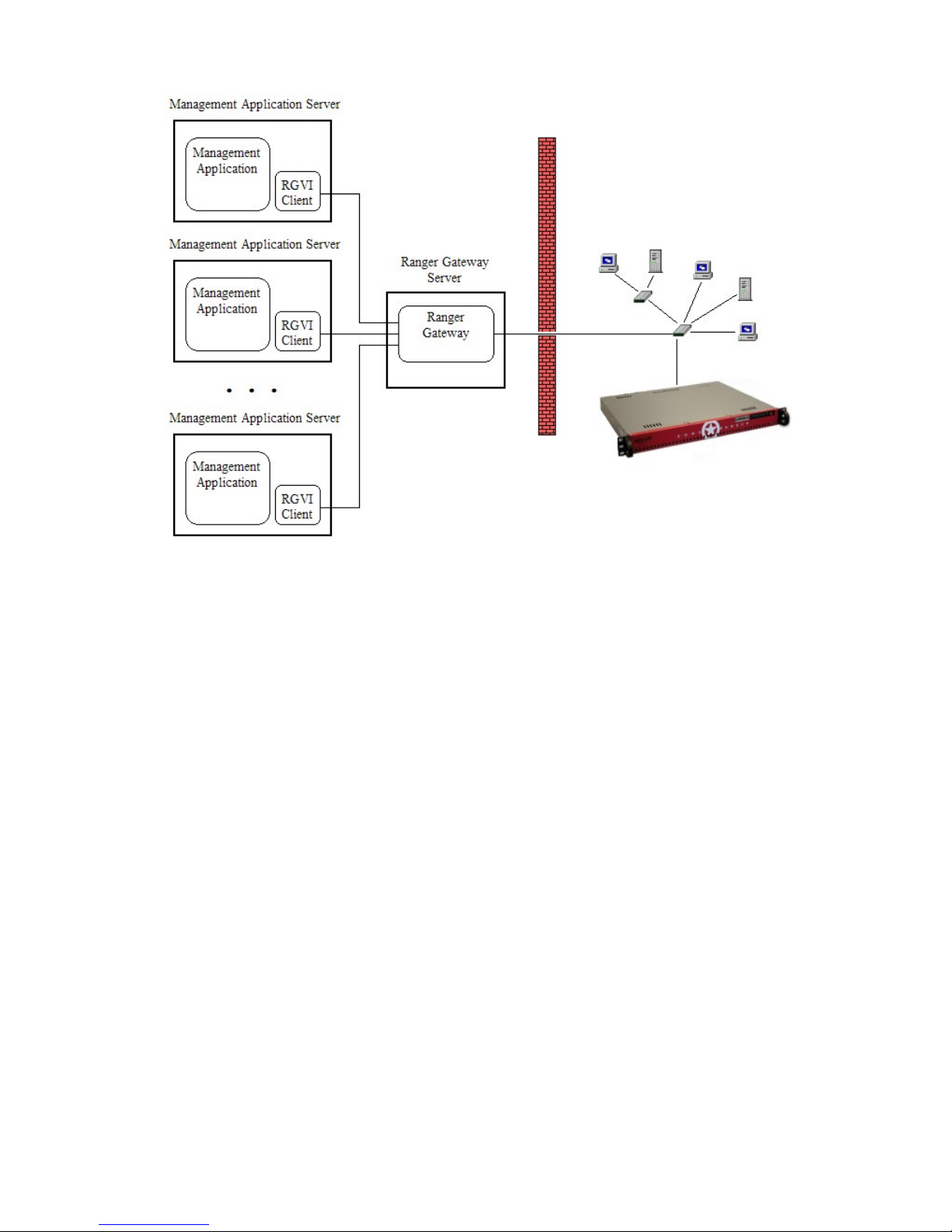
Figure 8-5. Sharing a Ranger Gateway among multiple Management Application Servers
The RGVI service in the Ranger Gateway is configured with a list of permitted clients, and each client
can be configured with its own list of host and/or subnet addresses to be intercepted, or can inherit the
list of host and/or subnet addresses configured for the GVI service. When a client connects to the RGVI
service within the Ranger Gateway, the service checks its configuration to verify that the client is
permitted to use the RGVI service, and if so, pushes the corresponding set of host and/or subnet
addresses to the client, which then configures the corresponding routes on the management application
server. Permitted clients can also be specified using address patterns or device groups, allowing multiple
client addresses to share the same list of host and/or subnets to be intercepted. Note that if the list of
hosts and/or subnets to be intercepted for RGVI client entry is modified while one or more of the set
of the matching clients is running and connected to the Ranger Gateway, these clients will need to be
restarted in order for the modifications to take effect.
In addition to checking the client's IP address to ensure that a client is permitted to access the RGVI
service, the Ranger Gateway also authenticates each client using SSL certificates. The list of trusted
RGVI subjects and corresponding certificate authorities can be configured using the trustSSL Ranger
Gateway command. Note that Ranger Gateway to ZoneRanger messaging and RGVI share a common
list of trusted certificate authorities, but have distinct trusted subject lists.
Although SSL-based authentication is always provided for RGVI client-to-server connections, the RGVI
service can optionally be configured to provide encryption and integrity checking for any data being
transferred between the client and the Ranger Gateway. The option to provide encryption and integrity
checking for data traffic can be enabled or disabled using the Ranger Gateway Viewer or the rgvi
Ranger Gateway command. Note that if the Ranger Gateway is configured to provide encryption and
integrity checking, all RGVI clients that can connect to that Ranger Gateway must also be configured to
provide encryption and integrity checking. Similarly, if encryption and integrity checking is disabled on
the Ranger Gateway, it must also be disabled on all RGVI clients.
By default, the RGVI client communicates with the Ranger Gateway using a custom UDP-based
protocol. The port on which the Ranger Gateway listens for incoming connections from RGVI clients is
configurable (default is 1194). Note that if the RGVI port on the Ranger Gateway is modified, it will
also be necessary to modify the configuration for each RGVI client to use the same port.
ZoneRanger 5.5 User's Guide
30
Page 31

In order to provide high availability, each RGVI client can be configured with the IP addresses of
multiple Ranger Gateways. When the client is started, it will attempt to connect to one of the Ranger
Gateways in the list. If the connection attempt succeeds, the RGVI client will direct all proxy traffic to
the connected Ranger Gateway. If the connection attempt fails, the RGVI client will attempt to connect
to a different Ranger Gateway. If the RGVI client has successfully connected to a given Ranger
Gateway, but subsequently loses connectivity, the client will time out and attempt to connect to a
different Ranger Gateway.
The RGVI service can be controlled and configured using the Ranger Gateway Viewer or the rgvi
Ranger Gateway command.
RGVI client installation and configuration instructions for various operating systems are provided in
Appendix J.
ZoneRanger 5.5 User's Guide
31
Page 32

Chapter 9: Joining
In the ZoneRanger architecture, the ability to proxy traffic between a management application and the
devices in a firewall-partitioned network requires two components:
• One or more ZoneRanger appliances, located in the same network partition as the managed
devices.
• An installed instance of the Ranger Gateway software component, which is typically installed
on the same server as one or more management applications3.
The role of the Ranger Gateway is to act as an interface between the ZoneRangers and management
applications, relaying proxy traffic to/from ZoneRangers that are able to communicate directly with the
managed devices.
For security purposes, before a Ranger Gateway can relay management traffic to/from a given
ZoneRanger, it must first be joined to that ZoneRanger. Joining is a simple process, initiated by the user,
and can be performed using any of the following user interface mechanisms:
• Ranger Gateway Viewer
• Ranger Gateway command
• ZoneRanger web interface
Joining essentially establishes a persistent relationship between a Ranger Gateway and a ZoneRanger, so
that the joined entities can cooperate in the provision of proxy services. Security for the joining process
is implemented in two layers:
1. The Ranger Gateway and ZoneRanger must authenticate each other using SSL certificates.
2. The Ranger Gateway and ZoneRanger must be configured with matching passcodes4.
SSL authentication, when properly configured, can provide a high level of security. In order for a Ranger
Gateway and a ZoneRanger to establish an SSL connection, the following conditions must be satisfied:
1. The Ranger Gateway must present an SSL certificate that has been signed by a certificate
authority recognized by the ZoneRanger, and must have a distinguished name that matches one
of the entries in the ZoneRanger’s configured list of trusted subjects.
2. The ZoneRanger must present an SSL certificate that has been signed by a certificate authority
recognized by the Ranger Gateway, and must have a distinguished name that matches one of the
entries in the Ranger Gateway’s configured list of trusted subjects.
By comparison, passcode authentication offers a more casual level of security, and is intended more to
prevent unintentional joining between a Ranger Gateway and a ZoneRanger.
3
The Ranger Gateway software can also be installed on a separate server, located in the same subnet as
the management application server.
4
When joining to a ZoneRanger from the Ranger Gateway, it is also possible to specify the passcode of
the ZoneRanger as part of the request, even if that passcode does not match the Ranger Gateway’s
configured default value.
ZoneRanger 5.5 User's Guide
32
Page 33
A single Ranger Gateway can be joined with up to 250 ZoneRangers. Given that each Ranger Gateway
instance typically serves a single management application instance, this allows a given management
application to extend its reach into many firewall-partitioned networks, providing that one or more
ZoneRangers have been installed in each such network. Similarly, each ZoneRanger can be joined with
up to 250 Ranger Gateway instances, allowing managed devices in the firewall-partitioned network
where the ZoneRanger has been installed to interact by proxy with a large number of management
applications. The many-to-many joining relationship between Ranger Gateways and ZoneRangers is
illustrated in the following figure.
Figure 9-1. Many to Many ZoneRanger configuration
The figure shows four Ranger Gateway instances, each joined with six ZoneRangers. Each of the
ZoneRangers is joined with all four Ranger Gateways. The number of joining relationships that need to
be established, then, depends on the number of management applications being used, and the number of
firewall-partitioned networks to be managed.
If there is a firewall between a Ranger Gateway and a ZoneRanger that need to be joined, as is typically
the case, a firewall rule must be configured, to allow the Ranger Gateway and ZoneRanger to
communicate. All management protocol traffic being proxied between a Ranger Gateway and a
ZoneRanger is multiplexed over a single TCP connection, so a single TCP firewall rule, specifying the
configured messaging port5 as the destination port is all that is required.
Note that the figure also shows two management applications: CiscoSecure ACS and a Trap/Syslog
Receiver that make use of a Ranger Gateway installed on a different server. This approach can be used
to reduce the number of Ranger Gateway instances, and associated firewall rules and joining
relationships, in cases where the nature and volume of the protocol traffic allows.
5
The default messaging port is TCP 4854.
ZoneRanger 5.5 User's Guide
33
Page 34

Chapter 10: Licensing
ZoneRanger may be a physical appliance or a virtual appliance (VM). When in the form of a physical
appliance, the ZoneRanger is manufactured with a particular license specifying the number of devices it
is allowed to manage. This license is a permanent license with no expiration date. When in the form of
a virtual appliance (VM), the ZoneRanger must obtain its license via a Ranger Gateway License Server
or via a provided Activation Key. This license will also specify the number of devices the ZoneRanger
is allowed to manage but it will have an expiration date and will need to be renewed periodically.
Ranger Gateway License Server
A Ranger Gateway, when configured with licenses provided by Tavve, may be a license server for any
ZoneRanger VMs joined to it. Once a ZoneRanger VM has joined to a Ranger Gateway License Server,
the Administration > License Activation page on the ZoneRanger VM web interface may be used to
specify which of the available licenses on the Ranger Gateway License Server should be allocated to this
ZoneRanger VM. Once the license is allocated to the ZoneRanger VM, the ZoneRanger VM is now
activated and must maintain communication with the Ranger Gateway License Server in order to
maintain its activation. If communications between the ZoneRanger VM and the Ranger Gateway
License Server is lost, the ZoneRanger VM license will eventually be deactivated.
The Administration > License Activation page may also be used to choose a different license to be
activated on the ZoneRanger VM from any available licenses on the Ranger Gateway License Server.
Whenever any license is activated on the ZoneRanger VM, the ZoneRanger software may restart.
If a new ZoneRanger VM license is activated that has fewer nodes than are currently managed by the
presently activated license, all managed nodes will be automatically unmanaged. For example, if a
ZoneRanger VM has an activated ZR-200 license with 150 managed nodes and the ZoneRanger VM is
then activated with a ZR-50 license, all of the 150 managed nodes will be automatically unmanaged
once the new license activation is complete.
If the expiration time is reached on a currently activated ZoneRanger VM, the ZoneRanger VM will
automatically be deactivated and restarted.
Activation Key
A ZoneRanger VM may be activated by using an Activation Key provided by Tavve. On the
Administration > License Activation page on the ZoneRanger VM web interface, an Activation Key
may be entered in order to activate the license on the ZoneRanger VM. The Pending Token as displayed
on the Administration > License Activation page must be provided to Tavve Software in order for an
Activation Key to be generated. Once the Activation Key is entered, the ZoneRanger VM will be
activated after a software restart.
ZoneRanger 5.5 User's Guide
34
Page 35

Chapter 11: Managed Nodes
For all node-based ZoneRanger models (e.g. ZR-50, ZR-200, and ZR-500), the majority of the proxy
and autonomous management services are available only to the set of nodes (a.k.a. devices) that have
been designated as managed. In each case, the model number indicates the maximum number of nodes
that can be managed by a given ZoneRanger.
In order for a node to be managed, it must first be discovered. Discovery, in the context of ZoneRanger,
is the process whereby a ZoneRanger analyzes its surrounding network and populates its database with
the nodes, interfaces, subnets, and TCP ports that are encountered. Depending on the discovery options
settings the discovery process can range from minimal (i.e. simply analyze a list of seed node addresses
in an attempt to identify devices that support multiple IP addresses) to fairly aggressive (e.g. ping
ranges, broadcast pings, ARP cache queries, and routing table queries). The ability to identify devices
(a.k.a. nodes) with multiple IP interfaces is particularly important, because it is the number of managed
nodes that is limited based on the license, not the number of interfaces. For example, a router may have
several interfaces, each with its own IP address. If the ZoneRanger discovery process is able to
determine that these IP addresses are associated with a single device, that device will count as a single
node towards the license limit.
Nodes can automatically be designated as managed during the discovery process, or can be managed or
unmanaged manually using the ZoneRanger web interface. If the Auto manage newly discovered
nodes discovery option is enabled, newly discovered nodes are automatically designated as managed
when discovery runs, until the license limit is reached. After the license limit is reached, any additional
newly discovered nodes are designated as unmanaged. After discovery runs, you can unmanage one or
more nodes, and manage others, using the ZoneRanger web interface.
If the Auto manage newly discovered nodes discovery option is not enabled, newly discovered nodes
are designated as unmanaged, regardless of the license limit. After discovery runs, you can use the
ZoneRanger web interface to manage one or more of the discovered nodes.
The ZR-SPX model has no license limit with respect to proxy and forwarding services. That is, a ZRSPX will proxy traffic to/from any device, regardless of whether or not that device has been designated
as managed or even exists in the database. Note that autonomous management features (e.g. ZoneRanger
polling, root cause) remain limited to managed nodes, even for the ZR-SPX model, and that the ZR-SPX
has a limit of 50 managed nodes.
The ZR-SPX model is engineered based on traffic capacity, rather than node limits. As such, customers
are encouraged to consult with Tavve Sales in order to determine the number of ZR-SPX units that
would be required for any given application/deployment.
ZoneRanger 5.5 User's Guide
35
Page 36

Chapter 12: Node Groups
There are many configuration areas in ZoneRanger which accept a list of IP addresses and/or address
patterns. The same list of devices may need to be applied to multiple configuration areas. Node Groups
represent a collection of address patterns that can be applied to the following IP address based
configurations:
• Forwarding rules
• TACACS+/RADIUS proxy rules
• Inbound TCP proxy rules
• Outbound ICMP proxy caching
• IP Interface polling
• SNMP Manager rules
• SNMP Disallowed lists.
Node Groups are maintained on the Configuration > Node Management page Node Groups tab of the
ZoneRanger Web GUI. Node Groups may contain any number of valid address patterns as well as other
Node Groups. When specifying a Node Group in a configuration rule or within another Node Group,
the name of the Node Group must be prefixed with '@' to indicate that the value should be interpreted as
a Node Group. For example, the Node Group “webservers” would be represented as @webservers. It
may represent the following:
10.254.1.[1-5]
10.10.23.25
@otherwebservers
Note that Node Groups do not contain hostnames.
ZoneRanger 5.5 User's Guide
36
Page 37
Chapter 13: Pooling/Redundancy/VIP/Grouping
ZoneRanger deployments typically place two or more ZoneRangers in each firewall-partitioned
network, for one or both of the following reasons:
• High availability (i.e. if one ZoneRanger fails, the other ZoneRanger(s) can handle the required
management protocol proxy traffic).
• High capacity (i.e. by deploying multiple ZoneRangers in a load balancing configuration, the
total volume of management protocol traffic that can be proxied to/from the firewall-partitioned
network is increased).
High availability and high capacity are supported by a variety of Ranger Gateway and ZoneRanger
mechanisms as described in the following sections.
Pooling
The simplest configuration for multiple ZoneRangers in the same network partition is referred to as
pooling. A pool of ZoneRangers is essentially a set of multiple ZoneRangers, each unaware of the
others, that are deployed in the same network partition and are joined to the same Ranger Gateway(s).
Each Ranger Gateway that uses the pool is configured with an understanding that each of the
ZoneRangers in the pool is equally capable of relaying management protocol traffic to a given set of
devices (i.e. the devices in the network partition where the ZoneRanger pool is deployed). The Ranger
Gateway can be configured to distribute management protocol proxy transactions across the pool in a
load-balancing fashion, in order to achieve high capacity. In addition, if the Ranger Gateway detects that
it is unable to communicate with one of the members of the pool, traffic will be distributed to the
remaining members, in order to achieve high availability.
Pooling is implemented within the Ranger Gateway’s Proxy Map service, and affects management
protocol traffic originated by the management application, such as ICMP proxy or SNMP Get/Set proxy.
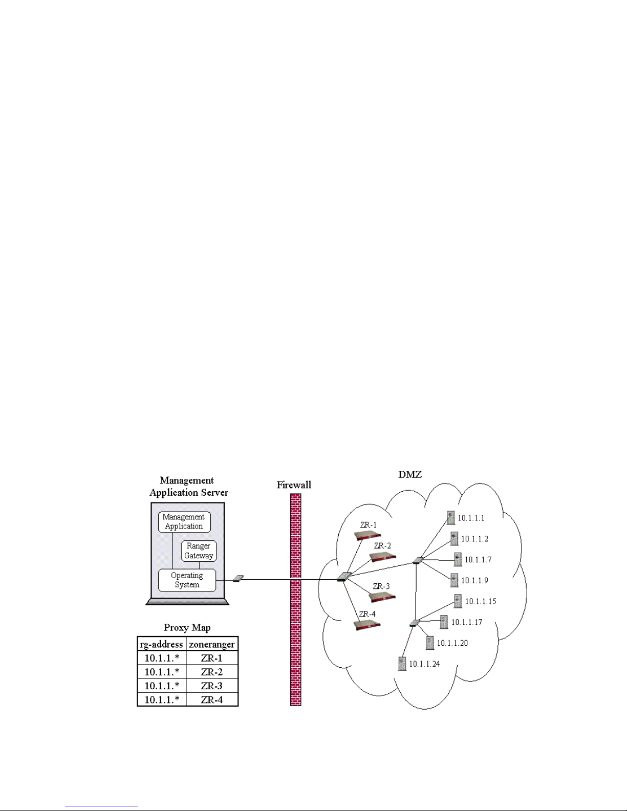
The following figure illustrates a simple pool of four ZoneRangers. Note that the Proxy Map
configuration indicates that each of the ZoneRangers is equally capable of relaying management
protocol traffic to any of the managed devices in the DMZ where they have been deployed.
Figure 13-1. ZoneRanger Pooling Example
ZoneRanger 5.5 User's Guide
37
Page 38
Redundancy
Redundancy is a more sophisticated form of multiple ZoneRanger configuration. When using
redundancy, a persistent relationship is configured between the redundant ZoneRangers, so that they
become aware of each other. When two or more ZoneRangers are configured to be redundant,
configuration changes to one of the ZoneRangers, including changes to configuration options associated
with managed devices, will automatically be propagated to the other ZoneRangers, making it easier to
keep the configurations of the redundant ZoneRangers in sync. Whenever a redundant ZoneRanger that
has been down or was otherwise unreachable is restored, and communication with its peers is
reestablished, the ZoneRanger will resynchronize its configuration with its peers in order to pick up any
configuration changes that may have occurred.
Redundant ZoneRangers perform discovery and polling independently. As such, discovery results and
device status information are not propagated between redundant ZoneRangers. If polling configuration
settings associated with discovered devices are modified on one ZoneRanger, the changes are
propagated to all redundant ZoneRangers, each of which will attempt to locate the corresponding device
in their own database of discovered devices, and make identical changes.
ZoneRangers can be configured to be redundant during initial configuration, or at a later time, using the
ZoneRanger web interface. Note that redundancy and pooling can be used simultaneously. That is, the
Proxy Map service on the Ranger Gateway can be configured to distribute management protocol traffic
across the set of redundant ZoneRangers, in the same way as across a simple pool of ZoneRangers. In
that sense, Redundancy provides all of the features of pooling, plus the added value of automatically
synchronizing the configurations of the redundant ZoneRangers. A redundant pool of ZoneRangers is
illustrated in the following figure.
Figure 13-2. Redundant ZoneRanger Pooling Example
ZoneRanger 5.5 User's Guide
38
Page 39
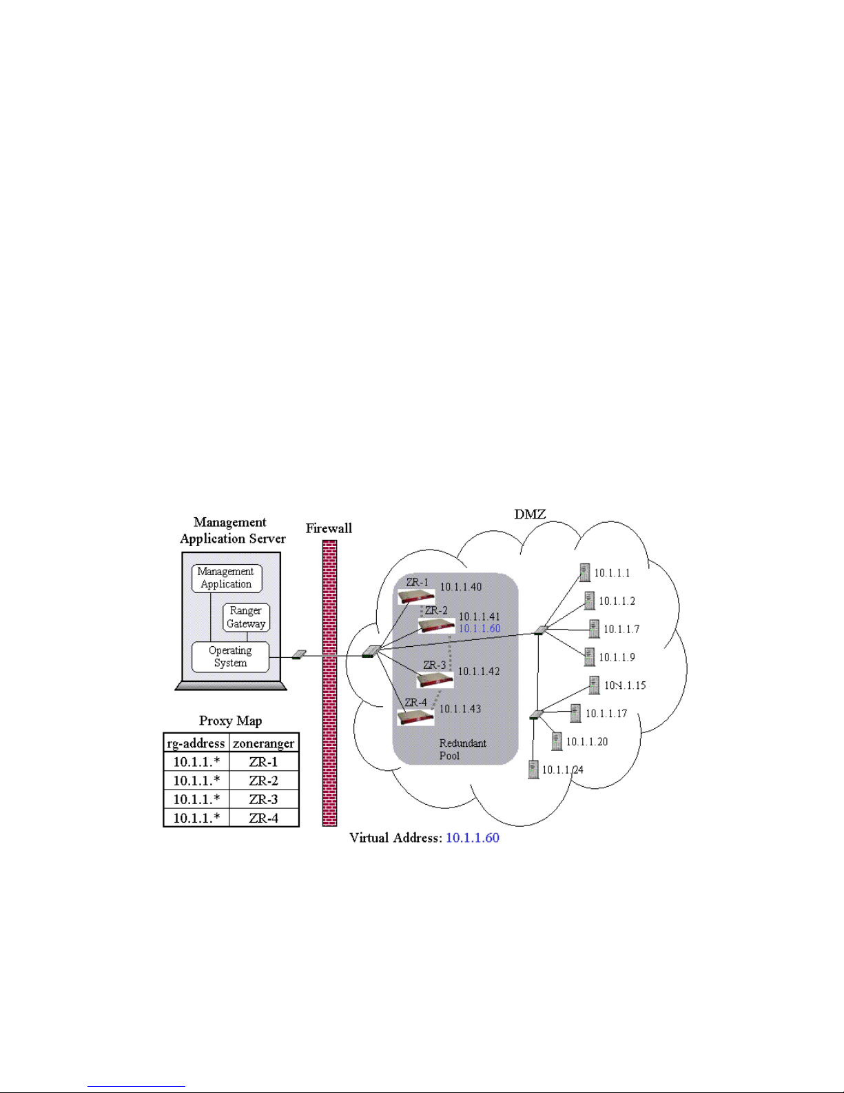
Virtual IP
Redundant ZoneRangers may be configured with a Virtual IP, forming a VIP Cluster.. Within a VIP
Cluster, a virtual IP address is defined and shared across a set of redundant ZoneRangers. At any given
time, one of the ZoneRangers will be active with respect to the virtual IP address (i.e. it is configured to
receive traffic destined for the virtual address), while the others will be passive. If the passive
ZoneRangers detect that the active ZoneRanger has failed, or is no longer communicating, one of the
passive ZoneRangers will become active, so that there should always be a healthy ZoneRanger able to
receive and process traffic directed towards the virtual address.
The advantage of creating a VIP Cluster is that managed devices can be configured to forward protocol
traffic such as SNMP traps, Syslog messages, NetFlow messages or sFlow messages to a single address
(i.e. the virtual IP address), and whatever ZoneRanger happens to be active on that address at that time
will relay the traffic to the intended management application(s) via one or more Ranger Gateways.
Note that in addition to the virtual IP address, each ZoneRanger also will have its own unique real
address. As such, an alternative to using virtual IP is to configure managed devices to forward
management protocol traffic to multiple ZoneRangers, specifying the real IP address in each case. In the
case of SNMP traps, and Syslog messages, each Ranger Gateway will remove the duplicate traffic, so
that each actual trap or message should only be forwarded once to the listening management
applications. This approach minimizes the possibility of lost traps or messages, at the cost of increased
management traffic (e.g. the managed device must forward each SNMP trap or Syslog message multiple
times). Creating a VIP Cluster will eliminate this additional traffic, at the cost of the possibility of lost
traffic during the brief period of time that it will take for a passive ZoneRanger to detect that the active
ZoneRanger has failed, and to become active.
Figure 13-3. Redundant ZoneRanger within a VIP Cluster
Note that in this figure, ZR-2 is currently active, with respect to the VIP address (10.1.1.60), while the
other three ZoneRangers are currently passive. Managed devices, in this case would typically be
configured to forward traffic such as SNMP traps and Syslog messages to the 10.1.1.60 address.
ZoneRanger 5.5 User's Guide
39
Page 40

Grouping
Grouping is another concept that applies when multiple ZoneRangers are deployed into the same
network partition. A set of ZoneRangers is considered to be grouped when they are all configured with
the same group name6. Grouping impacts the behavior of the Ranger Gateway with respect to two proxy
features:
• The Ranger Gateway’s algorithm for de-duplicating forwarded SNMP traps and Syslog
messages depends on grouping, in that if a Ranger Gateway receives duplicate SNMP traps or
Syslog messages forwarded from multiple ZoneRangers, the duplicates will be removed only if
the configured group names of the forwarding ZoneRangers are identical.
• When using one of the three-part community string formats (i.e.
community@ZoneRanger@device or device@ZoneRanger@community) in
conjunction with SNMP Get/Set proxy, if the group name is used in place of the ZoneRanger in
the community string, the Ranger Gateway will select one of the joined ZoneRangers in the
group to relay the request to the managed device.
Note that it is possible to configure a set of ZoneRangers to have the same group name with or without
configuring redundancy. For example, if a pool of ZoneRangers is configured without configuring
redundancy, the group names of each of the ZoneRangers in the pool still need to match in order for
SNMP trap and Syslog message de-duplication to work properly. If redundancy is configured, the
redundant ZoneRangers will automatically have the same group name (i.e. the group name from the
source ZoneRanger will be propagated to any target ZoneRangers).
6
The group name of a ZoneRanger can be configured during initial configuration, or at any subsequent
time via the ZoneRanger web interface.
ZoneRanger 5.5 User's Guide
40
Page 41

Chapter 14: Proxy Access Control
Proxy Access Control on the Ranger Gateway governs the handling of management traffic originated by
management applications and destined for managed devices (e.g. ICMP request, SNMP Get/Set request,
HTTPS, SSH, FTP), enabling users to configure what clients are allowed to use what protocols for given
managed devices. Traffic originated by managed devices is typically governed by configuration rules
within the ZoneRanger (e.g. forwarding rules, TACACS+/RADIUS server groups), and is outside of the
scope of Proxy Access Control.
Whenever a proxy request is received from a management application, the Ranger Gateway uses Proxy
Access Control configuration rules to determine:
• Whether the proxy request should be allowed or discarded.
• If the request is allowed, the protocol being used (e.g. for validation, or special processing).
• If the request is allowed, the port translation rule, if any, that should be applied before
presenting the request to a managed device.
Proxy Access Control is organized into two stages, based on two configuration tables, the portMap table
and the portConfig table:
• The portMap table consists of an ordered set of rules of the following form:
(src-address, dest-address, port-config-name)
where src-address is the IP address associated with the requesting client, dest-address
is the IP address associated with the target managed device, and port-config-name is the
name of the port configuration to be used in the second stage.
In the first stage, the Ranger Gateway takes the src-address and dest-address for a
given request, and searches the portMap table for the first matching rule. If no matching rule is
found, the request is discarded.
• The portConfig table consists of a set of rules of the following form:
(port-config-name, transport, rg-port, protocol, zr-port)
where port-config-name is the name of a port configuration (as identified in the previous
stage), transport indicates whether the request is using ICMP, UDP, or TCP, rg-port is
the destination port associated with the request as received by the Ranger Gateway, protocol
identifies the management protocol to be used for the request, and zr-port either specifies
the destination port that the ZoneRanger should use when forwarding the request to the target
device, or a translation rule that can be used to calculate the port that should be used based on
the rg-port.
In the second stage, the Ranger Gateway takes the port-config-name that was identified in
the first stage, the transport associated with the request, and, where applicable, the
destination port associated with the request (a.k.a. rg-port) and searches the portConfig table
for the first matching rule. If no matching rule is found, the request is discarded. Note that if the
transport is ICMP, the rg-port, protocol, and zr-port fields are not used.
To illustrate this process, consider the network and configuration tables in the following figure:
ZoneRanger 5.5 User's Guide
41
Page 42
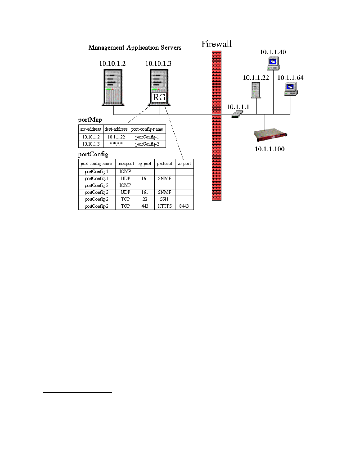
Figure 14-1. Proxy Access Control Example
This figure shows two management application servers (10.10.1.2 and 10.10.1.3), only one of which
(10.10.1.3) contains a Ranger Gateway. The 10.10.1.2 server is assumed to be using the 10.10.1.3 server
to relay management traffic7. According to the portMap table, if an application running on server
10.10.1.2 initiates a request destined for device 10.1.1.22, the port configuration named portConfig-
1 will be selected. If the same application initiates a request for any other managed device, no matching
port configuration will be found, and the request will be discarded. According to the portConfig table,
the portConfig-1 port configuration allows ICMP proxy and SNMP proxy on UDP port 161.
Requests from 10.10.1.2 to 10.1.1.22 involving other transport protocols and/or ports will be discarded.
Referring back to the portMap table, if an application running on server 10.10.1.3 initiates a request to
any of the managed devices, the port configuration named portConfig-2 will be used, because the
*.*.*.* destination address pattern will match all destination addresses. The portConfig table shows
that portConfig-2 allows ICMP proxy, SNMP proxy on UDP port 161, SSH proxy on TCP port 22,
and HTTPS proxy on port 443 (which will be translated to port 8443 before presenting the request to the
target device). Requests from 10.10.1.3 involving other transport protocols and/or ports will be
discarded.
Although standard well-known port values have been used in this example for each management
protocol, it is also possible to allow supported protocols to be used on non-standard ports (e.g. to
confuse, or hide from port scanners, for improved security).
7
A management application server with no Ranger Gateway installed can proxy traffic through a
Ranger Gateway installed within another server in a variety of ways, including SOCKS, joined
ZoneRanger proxy ports (i.e. 200xx), or by enabling IP forwarding on the Ranger Gateway server, and
configuring the other server to route management traffic to the Ranger Gateway server.
ZoneRanger 5.5 User's Guide
42
Page 43

The intent of the two-stage approach is to allow a small number of port configurations to be defined, and
re-used across multiple devices. As an example, it may be useful to define custom port configurations
for specific device types (e.g. Windows server, Cisco router), and configure the portMap table so that the
appropriate port configuration is used in each case. When this approach is used, the port configuration
details only need to be specified once per device type.
The portMap table also supports the use of address patterns (see Chapter 2) and device groups (see
Chapter 7) in the src-address and dest-address fields, in order to allow a single rule to be
applied to multiple devices.
The default portMap configuration, for a new ZoneRanger, is as follows:
*.*.*.* @ZoneRanger ZoneRangerDefault
*.*.*.* *.*.*.* Default
This configuration indicates that requests from any source directed towards a joined ZoneRanger will be
governed by the ZoneRangerDefault configuration, and that all other requests will be governed by the
Default configuration. The ZoneRangerDefault rule is configured first, so that requests directed towards
ZoneRangers will match that rule, as opposed to the Default rule. In order to restrict the Ranger
Gateway so that only traffic originated by applications on the Ranger Gateway server itself will be
processed, the portMap table would need to be configured as follows:
@Local @ZoneRanger ZoneRangerDefault
@Local *.*.*.* Default
Note: When restricting the Ranger Gateway to only accept local traffic it is highly recommended that
the @Local device group be specified, as opposed to specifying individual local IP addresses. The
source address for traffic received via GVI or RGVI will typically be a special address associated with
the underlying virtual point-to-point interface, so configuring rules based on specific IP addresses may
not produce the expected results.
The Default port configuration for a new ZoneRanger contains the following rules:
Default TCP 22 SSH
Default TCP 443 HTTPS
Default UDP 161 SNMP
Default ICMP
This configuration allows the use of SSH on TCP port 22, HTTPS on TCP port 443, SNMP on UDP port
161, and ICMP. The ZoneRangerDefault port configuration contains the following rules:
ZoneRangerDefault TCP 22 SSH
ZoneRangerDefault TCP 23 TELNET
ZoneRangerDefault TCP 80 HTTP
ZoneRangerDefault TCP 443 HTTPS
ZoneRangerDefault TCP 5432 SQL
ZoneRangerDefault UDP 161 SNMP
ZoneRangerDefault ICMP
ZoneRanger 5.5 User's Guide
43
Page 44

This configuration includes all of the rules from the Default configuration, plus the ability to use Telnet
on TCP port 23, HTTP on TCP port 80, and SQL on port 5432. Note that these rules only govern access
to the ZoneRanger via proxy through the Ranger Gateway. Direct access to ZoneRanger ports can be
enabled and/or disabled from the Configure > System page Ports tab on the ZoneRanger web interface
or using the Ranger Gateway portControl command.
The rg-port value in a port configuration rule can indicate a specific port, as described earlier, but can
also indicate a contiguous range of ports. For example, adding the following rule would enable SSH to
be used on TCP ports in the range 300-310:
Default TCP 300-310 SSH
Port transformations can also be used with port ranges. For example, the following rule would enable
SSH to be used on TCP destination ports in the range 300-310, but would transform these ports to the
8300-8310 range before forwarding protocol messages to the target devices:
Default TCP 300-310 SSH *+8000
Similarly, the following rule would enable SSH to be used on TCP destination ports in the range 300310, but would transform these ports to the 250-260 range before forwarding protocol messages to the
target devices:
Default TCP 300-310 SSH *-50
There may be times when it is useful to proxy a TCP-based management protocol that is not explicitly
supported by ZoneRanger (e.g. a proprietary or vendor-specific protocol). This form of proxy can be
enabled by adding a port configuration rule, specifying TCP as the protocol. For example:
Default TCP 300-310 TCP
Note that where TCP is specified as the protocol, the ZoneRanger does not provide any application
protocol inspection/filtering. However, given that ZoneRanger provides a break in the TCP protocol (i.e.
there are two TCP connections for each proxy session: one between the management application and the
Ranger gateway, and one between the ZoneRanger and the managed device), the management
application is essentially protected from TCP/IP layer attacks.
For each joined ZoneRanger, the Ranger Gateway allocates a set of special ports that can be used to
proxy management protocol traffic to the ZoneRanger itself. The ports assigned for each joined
ZoneRanger can be listed using the listTcpPorts command on the Ranger Gateway. These special
ports are typically allocated in the 20000’s range. For example, for a single joined ZoneRanger, the
listTcpPorts command might display the following:
ZR-Name http=20005 https=20006 sql=20007 ssh=20008 telnet=20009
Access to joined ZoneRangers via these special ports is also governed by port configuration rules. When
the Ranger Gateway receives a request on one of these special ports, the Ranger Gateway identifies the
ZoneRanger associated with the port, then maps the protocol associated with the port to the
corresponding port on the ZoneRanger8, according to the following table:
Protocol Port
http 80
https 443
sql 5432
ssh 22
telnet 23
8
Note that in some cases the port on the ZoneRanger is an internal port that can only be accessed by
proxy through the Ranger Gateway.
ZoneRanger 5.5 User's Guide
44
Page 45

Once the ZoneRanger address and the port on the ZoneRanger have been identified, the Ranger Gateway
looks up the applicable port configuration in the portMap table, based on the source address and
ZoneRanger address, then looks for the first matching rule in the portConfig table, based on the
transport (TCP) and the ZoneRanger port. For example, assuming the listTcpPorts command output
is as follows:
ZR-1 http=20005 https=20006 sql=20007 ssh=20008 telnet=20009
and if the ZoneRanger named “ZR-1” has an IP address of 10.10.4.5, if a request comes in on port
20008, the ZoneRanger address and port will be:
address=10.10.4.5, port=22
The Ranger Gateway will look first for a matching rule in the portMap table, using 10.10.4.5 as the
destination address, then will look for a matching rule in the portConfig table using 22 as the rg-port.
Assuming the default portMap and portConfig configuration, the following rules will be selected and the
request will be allowed to proceed:
• portMap:
*.*.*.* @ZoneRanger ZoneRangerDefault
• portConfig:
ZoneRangerDefault TCP 22 SSH
Although at first glance this approach for handling the special Ranger Gateway ports may seem a little
complicated, it has a significant advantage in that it allows access to a specific ZoneRanger/service to be
governed by a single rule, regardless of whether the service is being accessed using special Ranger
Gateway ports, or more directly via the GVI. In essence, access to a ZoneRanger service via a special
Ranger Gateway port is made to look like the equivalent GVI request, then is processed accordingly.
ZoneRanger 5.5 User's Guide
45
Page 46

Chapter 15: Proxy Caching
One of the primary advantages of ZoneRanger is that it is able to act as a proxy for management traffic
on behalf of a wide variety of management applications. As a result, it is possible to have multiple
management applications simultaneously proxying ICMP and SNMP traffic through a common pool of
ZoneRangers to a common set of managed devices. As the number of management applications
increases, and as polling rates increase, managed devices and the networks in which they reside may
become inundated with repeated requests for the same information from different applications.
The ZoneRanger proxy caching feature addresses this issue by saving results of recent ICMP and SNMP
proxy requests in an internal database, and using this cached information to respond to subsequent
requests, as opposed to passing the proxy requests on to the managed devices.
ICMP and SNMP proxy caching are enabled and configured separately, as described in the following
sections.
ICMP Proxy Caching
ICMP proxy caching is configured based on rules associated with specified IP addresses or IP address
ranges. Options associated with each rule include the following:
• Whether or not a successful ping request to a managed device will be remembered in the cache,
and how long a cached response will be considered to be valid.
• Whether or not an unsuccessful ping request to a managed device will be remembered in the
cache, and how long a cached response will be considered to be valid.
When an ICMP ping request is received by the ZoneRanger, if ICMP proxy caching is enabled, the
ZoneRanger will attempt to locate a matching caching configuration rule, and a cached result:
• If a valid cached result is found, based on the applicable configuration rule, the ZoneRanger
will immediately send a positive response back to the Ranger Gateway, if the cached result was
positive, or will discard the request if the cached result was negative.
• If there is no cached result, or if the cached result is determined to have expired, the request will
be forwarded on to the managed device and will be processed normally.
Whenever an ICMP proxy request is forwarded to a managed device, the cache is refreshed based on the
result. If the managed device responds to the ping, a positive result will be stored in the cache with the
timestamp updated to the current time. If the request times out, a negative result will be stored in the
cache.
SNMP Proxy Caching
SNMP proxy caching is configured based on rules associated with specific SNMP Object Identifiers
(OIDs). Each rule has associated options specifying whether or not caching is enabled for that OID
value, and if so, how long a cached response will be considered to be valid. When an SNMP Get/Set
request is received by the ZoneRanger, if SNMP proxy caching is enabled, the ZoneRanger will inspect
the OIDs specified in the request and attempt to locate matching caching configuration rules, and
associated cached results:
• If valid cached results are found for all of the specified OIDs, the ZoneRanger will immediately
send a response back to the Ranger Gateway with the cached values.
ZoneRanger 5.5 User's Guide
46
Page 47

• If valid cached values are found for some but not all of the specified OIDs, a pared down
request will be forwarded to the managed device, with the OIDs associated with valid cached
results removed. When the response comes back from the managed device, the returned values
will be stored in the cache and combined with the previously located cached values and the
resulting response will be returned to the management application via the Ranger Gateway.
• If no valid cached results are found, the entire request will be forwarded to the managed device,
the returned values will be stored in the cache, and the result will be returned to the
management application via the Ranger Gateway.
Whenever an SNMP proxy request is forwarded to a managed device, the cache is refreshed based on
the results with the timestamp updated to the current time.
SNMP proxy caching is based on OIDs so that users can configure different expiry times for different
types of data. For example, information that is subject to frequent change, such as the status of an
interface (i.e. ifOperStatus) should only be cached for a short period of time, if at all, while information
that is relatively static, such as the contact name for a device (i.e. sysContact) can reasonably be cached
for a relatively long period of time.
When the ZoneRanger searches for a rule to match a requested OID value, the OID value associated
with each configured rule is treated as a prefix. As such, each rule is considered to match the specified
OID value, and also to match the tree of OID values that begin with the specified value. For example, if
the ZoneRanger were to receive a request for OID 1.3.6.1.2.1.1.4, a configured rule with OID
value 1.3.6.1.2.1.1 would be treated as a match. This approach allows a single configured rule to
be applied to a large number of OIDs, effectively reducing the number of rules that need to be
configured. It is important to note that the configured rules are searched in order, and the first matching
rule for a given OID is used. For example, if the following rules were configured:
1.3.6.1.2.1.1.4, 10 minutes
1.3.6.1.2.1.1, 5 seconds
If a request for OID 1.3.6.1.2.1.1.4 is received, the first rule will be applied, but if a request for OID
1.3.6.1.2.1.1.5 is received, the second rule will be applied.
ZoneRanger 5.5 User's Guide
47
Page 48

Chapter 16: Proxy Map
The Proxy Map service in the Ranger Gateway supports the handling of management traffic originated
by management applications and destined for managed devices (e.g. ICMP request, SNMP Get/Set
request, HTTPS, SSH, FTP), enabling users to configure which ZoneRangers should be used to proxy
traffic for given managed devices. Traffic originated by managed devices is typically governed by
configuration rules within the ZoneRanger (e.g. forwarding rules, TACACS+/RADIUS server groups),
and is outside of the scope of the Proxy Map service.
The Proxy Map service provides the following functions:
• For each proxy transaction (for example, ICMP echo request, SNMP request, SSH session
request), the Proxy Map service identifies one or more joined ZoneRangers that are able to
relay the proxy traffic to the target device, and selects one of these ZoneRangers to handle the
given transaction.
• If network address translation (NAT) is in effect, the Proxy Map service translates the target
device address associated with the request at the Ranger Gateway to the corresponding device
address that the selected ZoneRanger must to communicate with the target device.
In simple ZoneRanger installations, the default Proxy Map configuration settings might be sufficient for
the Proxy Map service to operate. For example, if a Ranger Gateway is joined to a single ZoneRanger,
and no NAT is in effect, the Proxy Map service does not need additional configuration information to
select a ZoneRanger and identify the target address for a proxy transaction. In general, the Proxy Map
service configuration must be modified if any of the following conditions are true:
• The Ranger Gateway is joined to multiple ZoneRangers that are managing different devices
(that is, the proxy map service cannot assume that any ZoneRanger can proxy traffic to any
managed device).
• The firewall(s) associated with one or more of the network zones where joined ZoneRangers
are installed are configured for NAT.
• IP Address Aliasing is being used (see Appendix D) and the alias IP addresses defined for
managed devices do not match the actual IP addresses.
ZoneRanger 5.5 User's Guide
48
Page 49
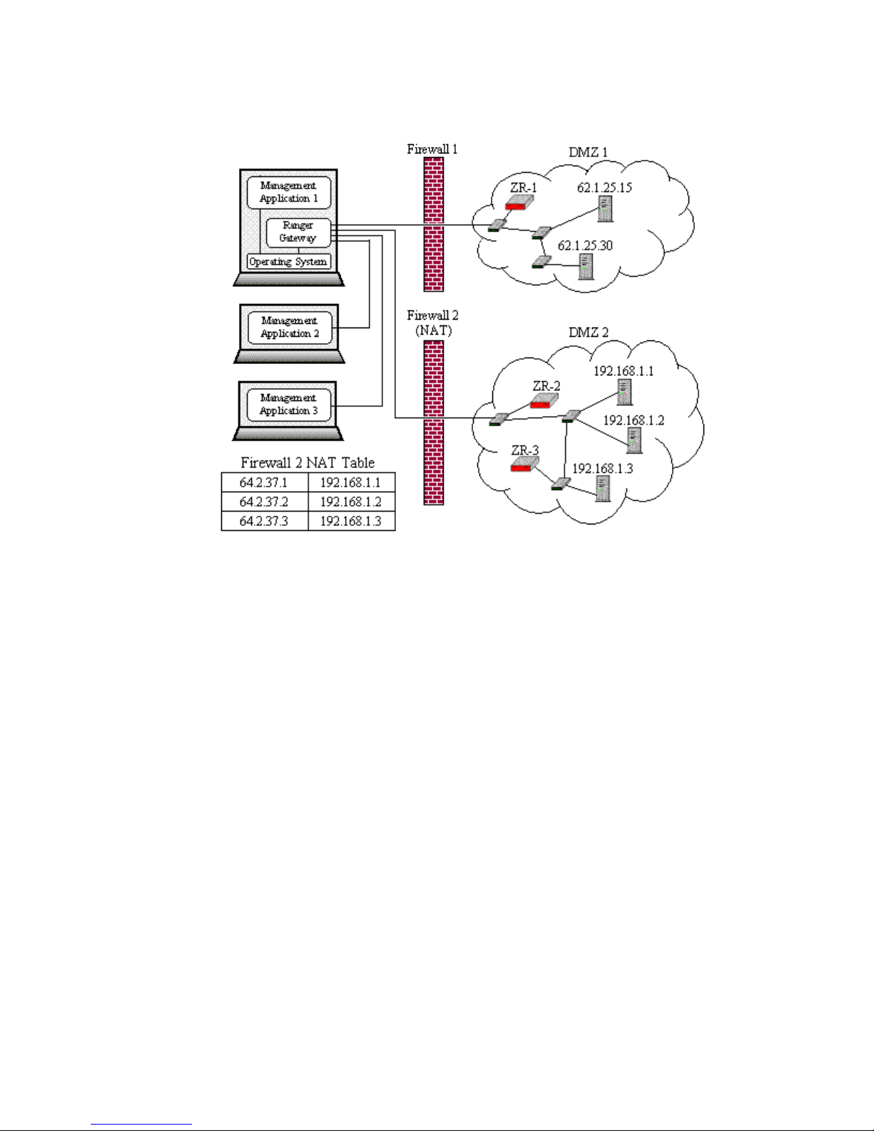
In order to describe the Proxy Map service in detail, it is useful to consider the network example shown
in the following figure:
Figure 16-1. Proxy Map Example
Note the following from this figure:
• A single Ranger Gateway supports multiple management applications. In general, management
applications can be co-resident with the Ranger Gateway software, or may execute on other
servers.
• The Ranger Gateway is joined to three ZoneRangers (ZR-1, ZR-2, and ZR-3). ZR-1 manages
devices in DMZ 1, while ZR-2 and ZR-3 manage devices in DMZ 3.
• Firewall 1 is not configured for NAT. Firewall 2 is configured to translate 64.2.37.*
addresses to 192.168.1.* addresses.
When any of the management applications in this example initiate a proxy transaction, the initial request
is relayed to the Ranger Gateway, along with some form of information that indicates the target DMZ
device, as described in the following examples:
• Management Application 1 could initiate a proxy transaction, such an ICMP echo
request, an SNMP Get request, or an SSH session request, directly to IP address 62.1.25.15.
The Ranger Gateway can intercept the request via GVI, and must select a ZoneRanger (ZR-1)
to relay the transaction. In this case, because no NAT is required, the Ranger Gateway will
indicate to the selected ZoneRanger that the target DMZ device address is 62.1.25.15.
• Management Application 1 could initiate a proxy transaction, such an ICMP echo
request, an SNMP Get request, or an SSH session request, directly to IP address 64.2.37.1.
The Ranger Gateway can intercept the request via GVI, and must select a ZoneRanger (ZR-2
or ZR-3) to relay the transaction. In this case, because NAT is required, the Ranger Gateway
will indicate to the selected ZoneRanger that the target DMZ device address is 192.168.1.1.
ZoneRanger 5.5 User's Guide
49
Page 50

• Management Application 2 could send an SNMP Get request to the Ranger Gateway,
indicating 62.1.25.30 as the target DMZ device using a community string convention. The
Ranger Gateway must select a ZoneRanger (ZR-1) to relay the transaction, and in this case,
because no NAT is required, will indicate to the selected ZoneRanger that the target DMZ
device address is 62.1.25.30.
• Management Application 3, a SOCKS-enabled SSH client, could initiate an SSH
session to address 64.2.37.3, using the Ranger Gateway SOCKS server. In this case, the
target device address is passed to the Ranger Gateway along the SOCKS protocol. The Ranger
Gateway must select a ZoneRanger (ZR-2 or ZR-3) to relay the session, and in this case, given
that NAT is in effect, must translate the target address to its corresponding address
(192.168.1.3) before passing the request to the selected ZoneRanger.
The Proxy Map service in the Ranger Gateway would be responsible for selecting the ZoneRanger for
each transaction and performing any necessary address translation before relaying the transaction to the
selected ZoneRanger. The Proxy Map service makes these decisions based on configuration settings,
ZoneRanger status information, and the content of an internal configuration table referred to as the
active proxy map. Each entry in the active proxy map consists of a the following fields:
• rg-address
The host name or IP address of the target device for a proxy transaction, as indicated to the
Ranger Gateway by the management application.
• zoneranger
The host name or IP address of a ZoneRanger that might be selected to relay a proxy
transaction.
• zr-address
The actual host name or IP address that the ZoneRanger should use to access the target device.
Note that if NAT is not in effect, this field can be omitted.
The active proxy map configuration table corresponding to the example above is as follows:
rg-address zoneranger zr-address
62.1.25.15 ZR-1
62.1.25.30 ZR-1
64.2.37.1 ZR-2 192.168.1.1
64.2.37.1 ZR-3 192.168.1.1
64.2.37.2 ZR-2 192.168.1.2
64.2.37.2 ZR-3 192.168.1.2
64.2.37.3 ZR-2 192.168.1.3
64.2.37.3 ZR-3 192.168.1.3
If the target address for a proxy transaction is 62.1.25.15, the Proxy Map service would look up all
entries with 62.1.25.15 in the rg-address column, and given that there is only one matching
entry, would select the corresponding ZoneRanger (ZR-1). Given that the zr-address column for
this entry is blank, the original target address would be passed on to the selected ZoneRanger.
If the target address for a proxy transaction is 64.2.37.3, the Proxy Map service would look up all
entries with 64.2.37.3 in the rg-address column. In this case, two entries are found, one for ZR-2
and one for ZR-3. The Proxy Map service selects one of the entries based on configured criteria and
status information, then passes the zr-address value from the selected entry (192.168.1.3) to the
selected ZoneRanger.
ZoneRanger 5.5 User's Guide
50
Page 51
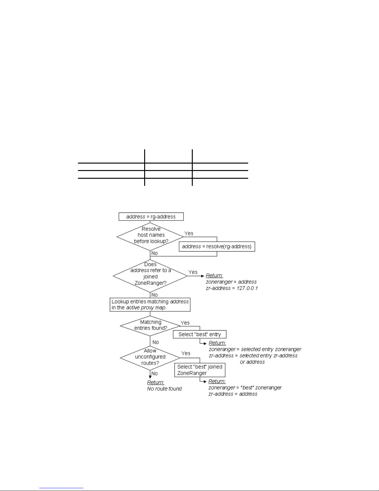
Note that although these examples have used IP addresses, the Proxy Map service can work with IP
addresses, host names, or combinations of both. In addition, the Proxy Map service can be configured
with rg-address values specified as address patterns, or device groups. For example:
• 62.2.37.*
• 62.2.37.[3-7]
• *.company.com
• @MyGroup
When NAT is in effect, each entry in the active proxy map must include a zr-address value. In order
for a single address pattern entry to be used for multiple devices, the zr-address must be specified as
an address transform. Using address patterns and address transforms, the active proxy map configuration
for the example network could be reduced to the following:
rg-address zoneranger zr-address
64.1.25.* ZR-1
64.2.37.[1-3] ZR-2 192.168.1.*
64.2.37.[1-3] ZR-2 192.168.1.*
The following flow chart illustrates the operation of the algorithm used by the Proxy Map service.
Figure 16-2. Proxy Map algorithm
This algorithm makes use of a number of configuration settings:
• If the resolve_host_names setting is enabled, the address associated with the target device
at the Ranger Gateway (that is, the rg-address) is resolved to an IP address before the active
proxy map lookup is performed.
ZoneRanger 5.5 User's Guide
51
Page 52

• When multiple ZoneRangers are available to relay a transaction for a given device, the selection
is based on the balance_zoneranger_selection setting. If this setting is enabled, the
Proxy Map service attempts to spread transaction load evenly across the available
ZoneRangers, by tracking recent history of selection decisions, and preferring ZoneRangers that
have been selected less frequently.
If this setting is disabled, the proxy map service tends to prefer the ZoneRangers from which
the Ranger Gateway has received the most recent communication. Disabling this setting
provides the highest reliability, because the best ZoneRanger is selected for each transaction,
and ZoneRangers that may be out of service tend to be bypassed. The disadvantage of this
approach is that proxy traffic might be concentrated on a single ZoneRanger, while other
available ZoneRangers may be bypassed.
• If no entries in the active proxy map match the given rg-address, and the
allow_unconfigured_routes setting is enabled, the Proxy Map service simply selects
the best available ZoneRanger, using the same criteria as described above, making the
assumption that any joined ZoneRanger should be able to reach the target device, and that no
NAT is in effect.
If this setting is disabled, and there are no matching entries in the active proxy map, the Proxy
Map service indicates that there is no route to the target device. The intent of the
allow_unconfigured_routes setting is to allow simple configurations (for example, one
Ranger Gateway joined to two ZoneRangers that both manage the same DMZ, with no NAT) to
operate without requiring the active proxy map to be configured. Where NAT is in effect, or
where a Ranger Gateway is joined to ZoneRangers that manage disjoint networks, this setting
must be disabled.
Proxy Map configuration settings can be modified using the Ranger Gateway Viewer or the proxyMap
command.
In some cases, the target of a proxy transaction might be the ZoneRanger itself (e.g. querying
ZoneRanger MIB values via SNMP proxy, or accessing the ZoneRanger text interface using SSH
proxy). To handle these cases, the Proxy Map service algorithm performs an initial check to see if the
rg-address matches the host name or IP address of a joined ZoneRanger. If a match is found, active
proxy map lookup is bypassed, and the indicated ZoneRanger is selected as the best route to itself. The
Ranger Gateway indicates 127.0.0.1 as the target address to the ZoneRanger, so that the ZoneRanger
will know that the intended target of the transaction is the ZoneRanger itself.
The Proxy Map service automatically collects entries with identical rg-address values into groups
and arranges these groups in an ordered list, according to the following rules:
• Groups of entries where the rg-address is specified as a specific value, as opposed to an
address pattern, are placed at the head of the list, so that they can be given preference.
• Groups of entries where the rg-address value is specified as an address pattern are placed at
the end of the list, in the order in which the groups were originally added to the active proxy
map.
When looking up entries for a given rg-address value, the Proxy Map service searches through this
ordered list, locates the first matching group, and selects a ZoneRanger from the entries in the first
matching group, based on ZoneRanger status information, the balance_zoneranger_selection
setting, and, where applicable, recent selection history, as described above.
The Proxy Map service can be especially helpful in situations where an organization needs to manage a
network where IP address ranges are reused across multiple network zones. For example, this situation
can arise whenever companies that have been using private Internet addresses are merged. In the
absence of NAT, the recommended solution is to define unique virtual addresses that are mapped to real
device addresses by the Proxy Map service.
ZoneRanger 5.5 User's Guide
52
Page 53
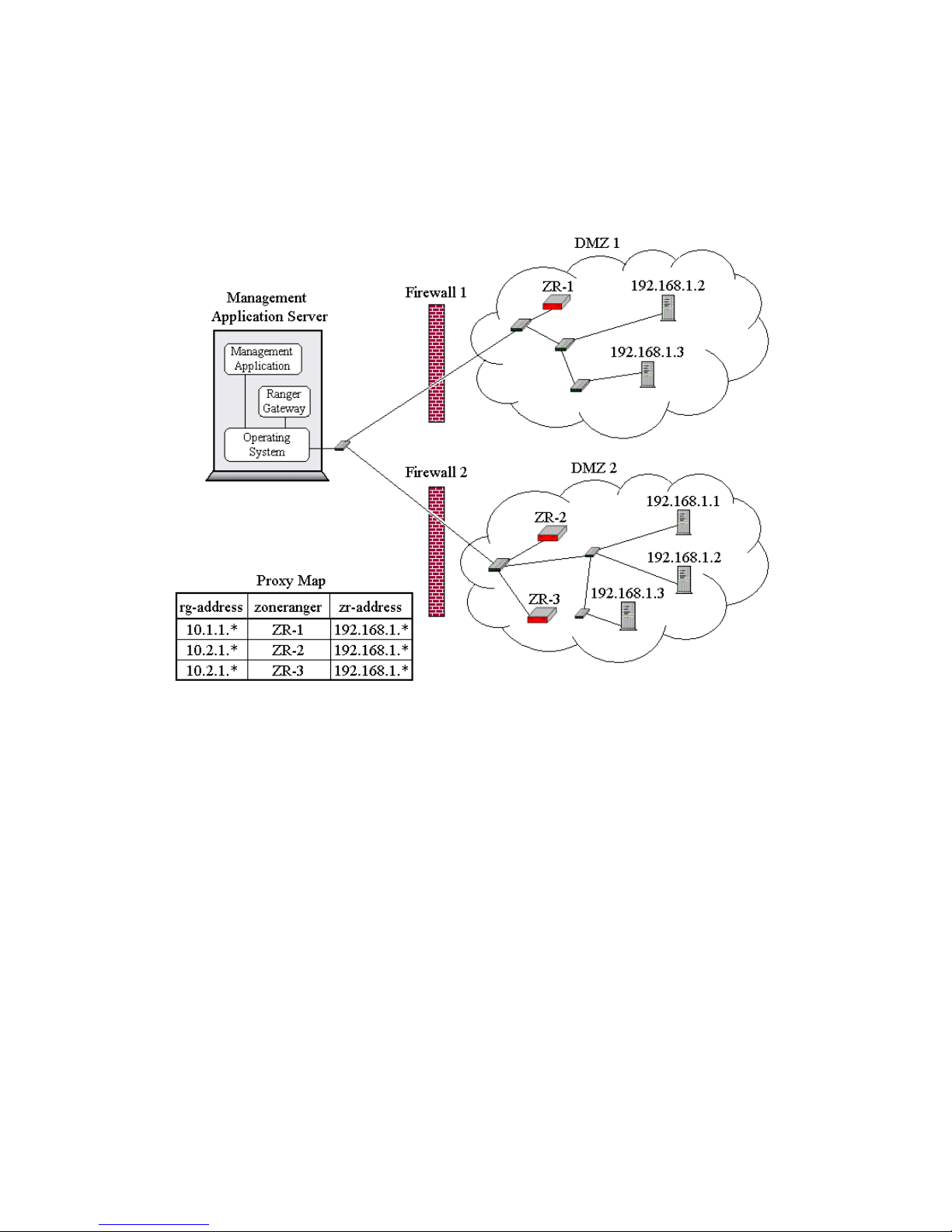
The proxyMap command on the Ranger Gateway can be used to generate, modify, and list the contents
of the active proxy map, and can also be used to view and modify configuration settings for the Proxy
Map service.
For example, consider the network shown in the following figure:
Figure 16-3. Duplicate IP Proxy Map algorithm
Note that addresses 192.168.1.2 and 192.168.1.3 are defined in both DMZ 1 and DMZ 2, and
that virtual address spaces 10.1.1.* and 10.2.1.* have been configured to map to the devices in
the two DMZ’s.
Even though this approach requires some amount of effort to manage and configure virtual addresses, it
should be noted that in most cases, the scope of these addresses is confined to the management
application server. As such, routers, firewalls, and other applications would have no awareness or
visibility of these addresses, resulting in simpler configuration and maintenance than alternatives such as
static NAT.
ZoneRanger 5.5 User's Guide
53
Page 54
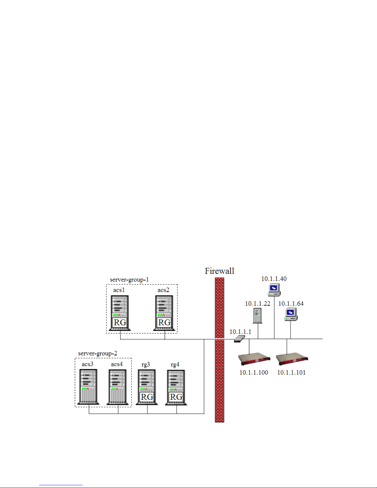
Chapter 17: Server Groups
ZoneRanger TACACS+ proxy and RADIUS proxy services can be used to proxy TACACS+ and/or
RADIUS traffic from managed devices to configured authentication, authorization, and accounting
(a.k.a. AAA) servers. Configuration of these proxy services is organized around the concept of server
groups, where each server group contains the following information:
• The name of the server group
• A set of entries of the following form:
(Ranger Gateway, TACACS+/RADIUS Server)
• Protocol options related to TACACS+
• Protocol options related to RADIUS
The underlying assumption behind server groups is that there may be multiple TACACS+/RADIUS
servers in a group, primarily for reasons of high availability, and that any of the TACACS+/RADIUS
servers in a group are equally able to handle authentication and authorization requests from a given set
of devices.
ZoneRanger also supports the ability to define multiple server groups, and to associate different server
groups with different device addresses, so that TACACS+/RADIUS traffic for different devices can be
handled by different groups of servers. Each server group has its own set of (Ranger Gateway,
TACACS+/RADIUS Server) entries and protocol-specific options. Once a set of server groups has
been defined, proxy rules must be configured for each protocol, associating managed devices, or groups
of managed devices with the server group that should be used for those devices. Each proxy rule
associates an IP address, or range of IP addresses, with a server group name. Separate proxy rule tables
are provided for TACACS+ and RADIUS.
For example consider the network shown in the following figure:
Figure 17-1. Server Groups Example
In this example, there are two redundant pairs of TACACS+/RADIUS servers:
ZoneRanger 5.5 User's Guide
54
Page 55

• acs1 and acs2
• acs3 and acs4
Note that acs1 and acs2 have the Ranger Gateway software installed on the same server, while acs3
and acs4 are served by Ranger Gateway instances installed on servers rg3 and rg4. Assume that
managed devices 10.1.1.22, 10.1.1.40, and 10.1.1.64 are to be served by acs1 and acs2,
and that the router (10.1.1.1) and ZoneRangers (10.1.1.100 and 10.1.1.101) are to be served
by acs3 and acs4. In order to support this configuration, the following server groups would be
defined:
• server-group-1
─ acs1, 127.0.0.1
─ acs2, 127.0.0.1
• server-group-1
─ rg3, acs3
─ rg3, acs4
─ rg4, acs3
─ rg4, acs4
The pairs configured for each server group have two parts:
• A Ranger Gateway that can be used to relay a request to a TACACS+/RADIUS server.
• The address that the Ranger Gateway should use to communicate with the TACACS+/RADIUS
server.
In server-group-1, where the Ranger Gateway instances are installed on the same physical servers
as acs1 and acs2, the Ranger Gateway address is the same as the server address, and the Ranger
Gateway can use the localhost address (127.0.0.1) to communicate with the TACACS+/RADIUS
server software installed on the same physical server. In server-group-2, where the Ranger
Gateway instances to be used are installed on separate servers (rg3 and rg4), either Ranger Gateway
instance can be used to relay traffic to either TACACS+/RADIUS server, so additional pairs are
configured, essentially listing all possible ways to reach all possible servers.
For any given request, the ZoneRanger will perform the following steps:
1. Identify the server group associated with the requesting device, based on configured rule tables
associated with the TACACS+ and RADIUS services.
2. Go through the set of (Ranger Gateway, TACACS+/RADIUS server) entries associated with
that server group, to identify a set of Ranger Gateway candidates. For example, if server-group1 was selected in the previous step, the Ranger Gateway candidates would be rg3 and rg4.
3. Select a Ranger Gateway from the set of Ranger Gateway candidates, based on recent
transaction history.
4. Relay the request to the selected Ranger Gateway, listing all TACACS+/RADIUS server
candidates associated with the selected Ranger Gateway. For example, if rg3 was selected, the
TACACS+/RADIUS server candidates would be: acs3 and acs4.
When the Ranger Gateway receives the relayed request, a TACACS+/RADIUS server will be selected
from the list of server candidates, based on recent transaction history, and the request will be relayed to
the selected server.
ZoneRanger 5.5 User's Guide
55
Page 56

Server Groups are configured on the Configure > Access Control page Server Groups tab of the
ZoneRanger web interface. Proxy rules for TACACS+ and RADIUS are configured on the TACACS+
and RADIUS tabs.
The simplest possible server group configuration is to define a single group. The following steps would
be required:
• Define a single server group named MyServerGroup
• Add the following proxy rule to the TACACS+ table:
*.*.*.* MyServerGroup
• Add the following rule to the RADIUS table:
*.*.*.* MyServerGroup
Using this configuration, the ZoneRanger will select a server from MyServerGroup to handle
TACACS+ and RADIUS requests from all managed devices. If there was a need to configure a second
server group to handle requests originated by specific devices, the following steps would be required:
• Define a new server group (e.g. MyOtherServerGroup)
• Insert proxy rules for the specific IP addresses or IP address ranges to the top of the TACACS+
table:
10.254.1.1 MyOtherServerGroup
10.254.2.[10-20] MyOtherServerGroup
*.*.*.* MyServerGroup
• Insert proxy rules for the specific IP addresses or IP address ranges to the top of the RADIUS
table:
10.254.1.1 MyOtherServerGroup
10.254.2.[10-20] MyOtherServerGroup
*.*.*.* MyServerGroup
When handling a TACACS+ or RADIUS request from a given device, the ZoneRanger will search
through the proxy rules table associated with the protocol being used for the first rule that matches the
requesting device’s address. As such, it is important to ensure that specific address rules are placed
ahead of overlapping range or wild-card rules.
ZoneRanger 5.5 User's Guide
56
Page 57

Chapter 18: Whitelist
Inbound
ZoneRanger can receive many different types of inbound data such as SNMP traps, Syslog
messages, TACACS+ requests, etc. In the case of a node-licensed ZoneRanger, the source of the
information will be verified as a managed node before the data will be processed based on the
ZoneRanger configuration. In the case of a ZR-SPX licensed ZoneRanger, no management check
occurs and the data will be processed based on the ZoneRanger configuration.
ZoneRanger may be configured with a specific set of devices (“whitelist”) from which it will
receive information. Thus, when the Whitelist feature is enabled, only inbound data with a source
address configured in the whitelist, will be further processed based on the ZoneRanger
configuration. If the source address of the inbound data is not specified in the whitelist, it will
dropped with no further processing.
For security purposes, the whitelist provides a mechanism for the ZR-SPX licensed ZoneRanger to
restrict the set of IP addresses from which it will accept information. In the case of the nodelicensed ZoneRanger, the use of the whitelist provides an additional security check as well as a
performance improvement in that the ZoneRanger will no longer need to verify whether or not the
incoming source address is from a managed node.
Joined Ranger Gateways and redundant ZoneRangers are automatically whitelisted, but will not
appear in the whitelist configuration. However, new Join requests from another Ranger Gateway
and Redundancy requests from another ZoneRanger will be subject to the whitelist. Thus, the IP
address of the new Ranger Gateway or new redundant ZoneRanger must be specified in the
whitelist for the request to be successful.
Outbound
ZoneRanger can proxy many different types of outbound data such as SNMP proxy, ICMP proxy,
TCP Proxy, etc. In the case of a node-licensed ZoneRanger, the destination of the request will be
verified as a managed node before the request will be processed based on the ZoneRanger
configuration. In the case of a ZR-SPX licensed ZoneRanger, no management check occurs and the
request will be processed based on the ZoneRanger configuration.
ZoneRanger may be configured with a specific set of devices (“whitelist”) to which it will send
information. Thus, when the Whitelist feature is enabled, only outbound data with a source address
configured in the whitelist, will be further processed based on the ZoneRanger configuration. If the
source address of the outbound data is not specified in the whitelist, it will dropped with no further
processing.
For security purposes, the whitelist provides a mechanism for the ZR-SPX licensed ZoneRanger to
restrict the set of IP addresses from which it will send information. In the case of the node-licensed
ZoneRanger, the use of the whitelist provides an additional security check as well as a performance
improvement in that the ZoneRanger will no longer need to verify whether or not the outgoing
source address is from a managed node.
Enforcing the whitelist for outbound requests will include any traffic sent from the ZoneRanger.
Thus is will effect Discovery, Root Cause, and Diagnostics requests initiated by the ZoneRanger as
well as requests proxied from a joined Ranger Gateway.
Joined Ranger Gateways and redundant ZoneRangers are automatically whitelisted, but will not
appear in the whitelist configuration. However, new Join and Redundancy requests initiated from
the ZoneRanger will be subject to the whitelist. Thus, the IP address of the new Ranger Gateway or
new redundant ZoneRanger must be specified in the whitelist for the request to be successful.
ZoneRanger 5.5 User's Guide
57
Page 58

Part III. ZoneRanger Services
Chapter 19: Discovery
Populating the ZoneRanger Database
Most ZoneRanger management services as well as proxy services for non-SPX ZoneRanger models
require the ZoneRanger database to be populated with information about the entities that the
ZoneRanger is intended to manage, such as nodes, interfaces, and TCP ports.
The process of analyzing the network and populating the ZoneRanger database is called discovery.
The process can range from a simple analysis to identify interfaces and subnets associated with a
predefined set of configured seed nodes, to an aggressive search for network device information,
combining techniques such as seed node analysis, ping range sweeps, ARP cache and route table
searches, broadcast pings, and root cause path analysis.
The extent and aggressiveness of the network analysis that is performed is based on a variety of
configuration options. This chapter describes how discovery is configured and executed on a
ZoneRanger.
The ZoneRanger database is organized into tables based on the types of entities that can be
discovered, such as nodes, interfaces, subnets, and TCP ports. The database also includes
relationships between entities, for example, the interfaces and TCP ports associated with a node, the
interfaces on a given subnet, and so on.
ZoneRanger discovery is an automated process that can be invoked manually as needed, or
configured to run periodically. The first time discovery runs on a ZoneRanger, the database is
populated based purely on the results of analyzing configured seed nodes and ping ranges. On
subsequent discovery runs, existing database content is merged with new discovery results so that
existing entities are updated with any changes, and new entities can be added to the database.
The Discovery Algorithm
To understand the various discovery configuration options, a simplified overview of the discovery
algorithm is helpful. The ZoneRanger discovery algorithm comprises two main types of activity:
• Accumulating addresses (that is, building a list of entity addresses to analyze)
• Analyzing addresses (that is, analyzing the entity addresses in the list).
The simplest way to accumulate addresses is to configure seed nodes and ping ranges. Configured
seed nodes are automatically added to the list of addresses to be analyzed. Any addresses in a
configured ping range that pass the include network/exclude network filter criteria and respond to a
ping are also added to the list of addresses to be analyzed.
The primary purpose of analyzing addresses is to identify nodes, interfaces, subnets, and TCP ports,
and the relationships between these entities, to populate the database.
In addition, depending on configuration options, additional addresses may be discovered while
analyzing addresses:
• In the interface table of a device
• In the ARP cache of a device
• In the route table of a device
• As the result of entities responding to broadcast ping requests
ZoneRanger 5.5 User's Guide
58
Page 59
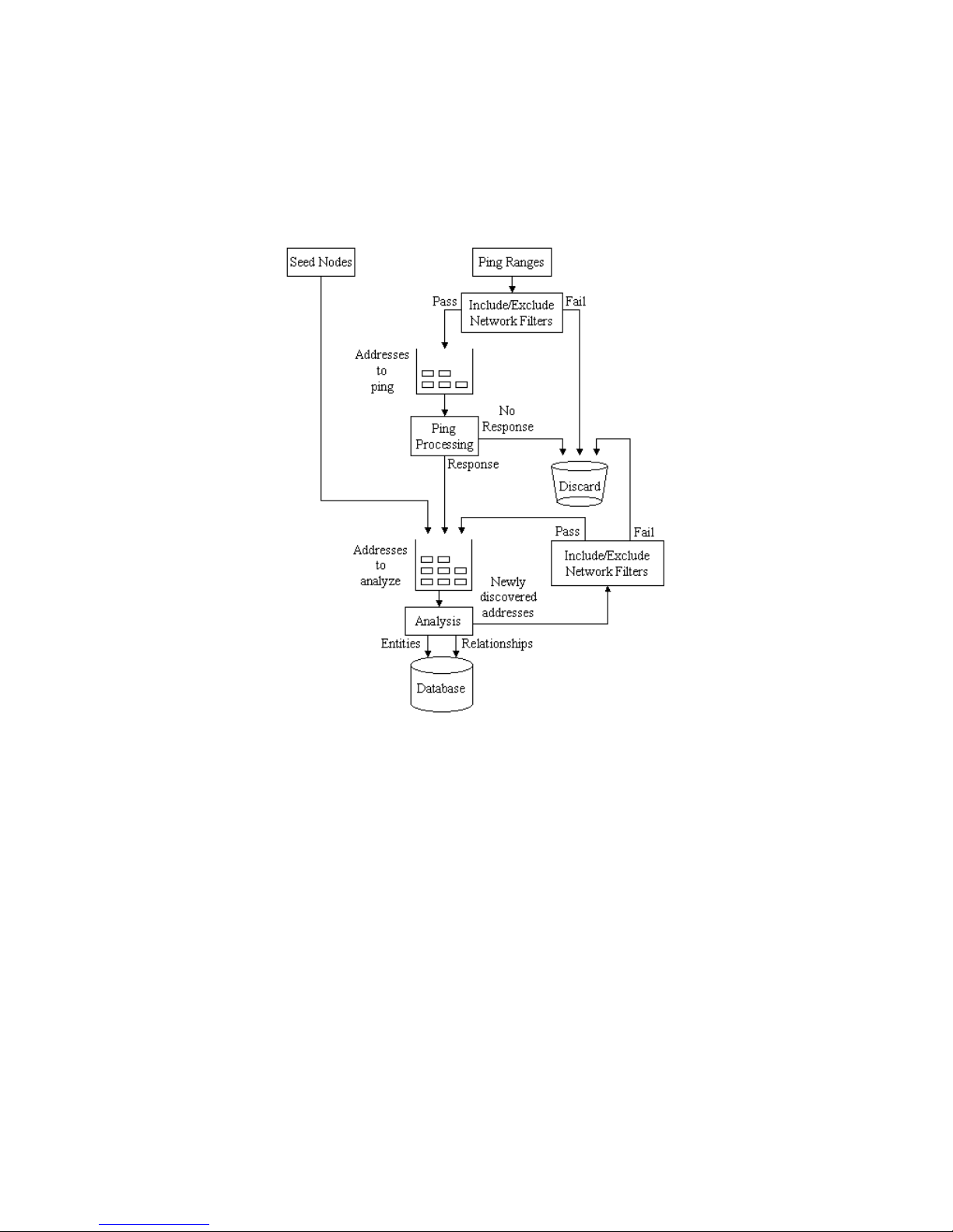
• During the routing path analysis required for the ZoneRanger root cause algorithm
Most of these mechanisms can be disabled using configuration options. To limit discovery to the
portions of the network that are of interest, addresses discovered during analysis activities are added
to the list of addresses to be analyzed only if they pass the include network/exclude network filter
criteria.
Figure 19-1. Discovery Algorithm
Default discovery behavior
The following default discovery settings (Configuration > Discovery) are generated during initial
ZoneRanger configuration:
• Search for additional nodes is enabled, and the Read IP route table, Read ARP cache,
and Broadcast ping enabled suboptions are enabled.
• Auto configure polling for newly discovered nodes is enabled.
• Auto Manage newly discovered nodes is enabled.
• The Seed Node List is populated with a single entry containing the default gateway IP
address as specified during initial ZoneRanger configuration.
• The Include Networks list is populated with a single entry, generated by taking the IP
address of the ZoneRanger specified during initial ZoneRanger configuration, and masking
off the last three octets. For example, if the ZoneRanger's IP address is 10.254.1.190, the
default include network is 10.0.0.0, which limits discovery to IP addresses of the form
10.n.n.n. The Exclude Networks list is initially empty.
• The Ping Ranges list is initially empty.
ZoneRanger 5.5 User's Guide
59
Page 60

• Several common TCP services and their associated ports are configured for discovery.
• A list of common sysObjectId to device type mappings is provided for commonly used
routers and switches.
During initial configuration, you are given the option to automatically run discovery after initial
configuration is complete. If this option is accepted, discovery runs, using these default settings,
immediately after the ZoneRanger completes its initial startup. In addition, the periodic discovery
option will be enabled with a default interval of 7 days. If this option is declined, you can wait until
the ZoneRanger starts up, modify the discovery settings as desired, and then either invoke discovery
manually or configure periodic discovery.
Incremental Discovery
As an alternative to running the full discovery algorithm, ZoneRanger also provides a mechanism
whereby the user can request that a short list of IP addresses or hostnames be scanned and
incrementally added to the database. When this mechanism is invoked, the ZoneRanger will scan
each provided IP address or hostname using SNMP and TCP and will update the ZoneRanger
database with the resulting information. If a new IP address or hostname is scanned, information for
that device will be added to the database. If an existing IP address or hostname is scanned, the
information in the ZoneRanger database for that device will be updated.
Note that incremental discovery is intended as a shortcut, to be used in cases where executing the
full discovery algorithm would consume too much time. Accordingly, the incremental discovery
algorithm does not gather subnet or path information for added devices. As a result, root cause
information will not be available for these newly added devices until a full discovery is executed.
ZoneRanger 5.5 User's Guide
60
Page 61
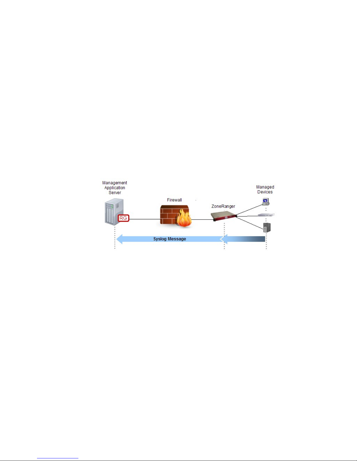
Chapter 20: Forwarding
ZoneRanger can be configured to listen for UDP traffic on specified ports, and forward that traffic
through a Ranger Gateway to a specified destination host and port that is reachable from the Ranger
Gateway. ZoneRanger can forward the following types of traffic:
• Trap
• Syslog
• sFlow
• NetFlow
• Generic UDP
Unless the ZoneRanger model is SPX, the traps, datagrams, and messages that ZoneRanger forwards
must originate from managed nodes. In the case of the SPX model, all information is forwarded
regardless of originating address. Forwarding rules are used to specify the type, source, and destination
of UDP information on the ZoneRanger to which to forward to a Ranger Gateway and ultimately a
management application.
Figure 20-1. ZoneRanger Forwarding
When UDP information is forwarded from the ZoneRanger to a Ranger Gateway to its ultimate
destination, the source address of the UDP information when it is received by the management
application is the address of the Ranger Gateway since it sent the UDP data. However, The Ranger
Gateway can be configured for particular protocols to “spoof” the address of the information to be that
of the original sending device instead of the address of the Ranger Gateway. Depending on the
requirements of the management application, spoofing may need to be configured for particular
protocols.
Forwarding Rules
Forwarding rules define the source and destination information of the UDP data to be forwarded.
Forwarding rules are configured on the ZoneRanger Configuration > Forwarding page. Each
forwarding rule is associated with a Ranger Gateway. Any number of forwarding rules may be
associated with a Ranger Gateway.
Forwarding rules are defined by the following criteria:
• Type of UDP traffic
• Source address of the UDP traffic
• Local port ZoneRanger listens for UDP traffic
• Destination host to which Ranger Gateway will forward UDP traffic
ZoneRanger 5.5 User's Guide
61
Page 62

• Destination port on destination host to which Ranger Gateway will forward UDP traffic
• Any filtering associated with this type of UDP traffic.
Forwarding Logging may be enabled to determine if UDP data is received by the ZoneRanger and
whether or not that UDP data passes a configured Forwarding Rule. The /log/udpFwd.log file can
be downloaded using a joined Ranger Gateway.
Trap Forwarding
ZoneRanger has the capability to receive SNMP traps from managed devices and forward those
traps through a Ranger Gateway to another application. When an SNMP trap is received by
ZoneRanger, the trap is verified to be syntactically correct. Thus, if the SNMP trap does not meet
the RFC definition of a correctly formatted SNMP trap, it will be discarded. If the SNMP trap is
inspected to determine whether or not it is syntactically correct, it will be processed by the
ZoneRanger forwarding service.
Trap filters are a named set of conditions which may be created in ZoneRanger to refine the
forwarding of SNMP traps. Through the ZoneRanger Configuration > Forwarding page Trap
Filters tab, a specific set of conditions may be created to apply to Trap Forwarding Rules. The
following conditions may be used in the creation of Trap Filters:
Condition Description
Trap Previously defined trap known by its name.
Enterprise ID SNMPv1 Enterprise OID of a trap or an OID
prefix. If the trap is not SNMPv1, its
Enterprise OID is described in RFC 3584.
Generic Type SNMPv1 Generic Type of a trap. If the trap is
not SNMPv1, its Generic Type is described in
RFC 3584
Specific Type SNMPv1 Specific Type of a trap. If the trap is
not SNMPv1, its Specific Type is described in
RFC 3584.
Trap OID SNMPv2c Trap OID of a trap or an OID prefix. If
the trap is SNMPv1, its Enterprise OID is
described in RFC 3584.
Variable
Binding
Agent SNMPv1 Agent of a trap. If the trap is not
Version SNMP version of the trap
Community SNMP community string. In the case of an SNMPv3
Filter Defines another previously defined trap filter
Variable Binding value of a trap, defined by
its index starting at 1. An '*' may be used at
the beginning and/or end of the value to denote
a wildcard match. Any '*' inside the value is
not treated as a wildcard
SNMPv1, the Agent is described in RFC 3584.
Multiple agents can be listed using commas
between IP addresses and may be an address
pattern.
trap, the user name will be compared rather
than the community string.
as a condition for this filter
Each condition may be defined as positive (default) or negative (“Not”). Also, each trap filter may
be configured so that the trap passes the filter if it meets all of the specified conditions or if it meets
at least one of the specified conditions.
ZoneRanger 5.5 User's Guide
62
Page 63

Each verified SNMP trap will be compared to the set of all configured Forwarding Rules. If the
SNMP trap meets the conditions of a Forwarding Rule, the SNMP trap is securely sent to the
corresponding Ranger Gateway to be ultimately sent to the Destination Host and Port as configured
in that specific Forwarding Rule. An SNMP Trap may match multiple Forwarding Rules, even to
the same Ranger Gateway. Unless the group name of the ZoneRangers which are forwarding the
traps is the same in which case the traps will be deduplicated, the traps will be forwarded multiple
times.
After a trap has passed a Forwarding Rule, the trap may also be configured to be converted to an
SNMPv1 or SNMPv2c. If an SNMPv3 or SNMPv2c inform is received and it is to be forwarded as
SNMPv1, it will be converted to a trap. In this case, the ZoneRanger will respond to the originating
device with an appropriate response after forwarding the trap.
The ZoneRanger is only able to process an incoming SNMPv3 Inform if there is a configured
SNMPv3 user or the Inform is using noAuthNoPriv Security Level. When the ZoneRanger is able
to process an incoming SNMPv3 Inform, the ZoneRanger will convert the Inform to an SNMPv3
Trap, forward the trap based on any configured forwarding rules, and respond to the client that the
Inform was received. ZoneRanger can forward SNMPv3 traps which use any Security Level
regardless of whether or not there is a configured SNMPv3 user.
There are some limitations when SNMPv3 users are not configured for SNMPv3 traps and informs:
1. Encrypted notifications will not match any trap filters using properties of the PDU with the
exception of version.
2. The ZoneRanger will not return responses to the client when it receives an SNMPv3 Inform.
3. Duplicate encrypted notifications will not be discarded on the Ranger Gateway.
Syslog Forwarding
ZoneRanger has the capability to receive Syslog messages from managed devices and forward those
messages through a Ranger Gateway to another application. When an Syslog message is received
by ZoneRanger, the message is inspected to determine whether or not to be syntactically correct.
Thus, if the message does not meet the RFC definition of a correctly formatted Syslog message, it
will be discarded. If the Syslog message is verified to be syntactically correct, it will be processed
by the ZoneRanger forwarding service. Otherwise, it will be discarded.
Syslog filters may be use to further refine the forwarding of messages within a particular syslog
forwarding rule. When configuring a syslog type Forwarding Rule, the Edit button allows for the
syslog filter specification. ZoneRanger has the ability to specially process syslog messages sent
from Cisco devices (Cisco Syslog). Specific syslog filters may be created related to Cisco syslog
messages. The following conditions may be used in the creation of syslog filter specification:
Condition Description
ZoneRanger 5.5 User's Guide
63
Page 64

Program Name Name of the program that generated the
syslog message, as the name appears in
the message.
Message Search Search string that the syslog message
must contain. The search string can be a
regular expression search
Cisco Syslog with Max
Severity
Syslog with Max
Severity
Syslog with Facility Syslog messages of the specified
Cisco syslog messages of the specified
severity or lower.
Note: The severities are more urgent the
lower the number, so this filter
includes the specified severity and
those that are more urgent.
Syslog messages of the specified
severity or lower.
Note: Syslog severities are more urgent
the lower the number, so this filter
includes the specified severity and
those that are more urgent.
severity or lower.
Note: Syslog severities are more urgent
the lower the number, so this filter
includes the specified severity and
those that are more urgent.
If multiple criteria are selected, a Syslog message must match all selected criteria to be forwarded.
Also, syslog filters allow messages to be forwarded as a syslog message or forwarded as an SNMP
trap. If the Cisco Syslog with Max Severity criteria is chosen, the correct Cisco trap for the
severity is generated. Otherwise, a Syslog trap with the specified Specific Type is generated.
NetFlow and sFlow Forwarding
ZoneRanger has the capability to receive NetFlow and sFlow packets from managed devices and
forward those packets through a Ranger Gateway to another application. When a NetFlow or sFlow
packet is received by ZoneRanger, the packet is inspected to determine whether or not to be
syntactically correct. For NetFlow, version 5 and version 9 packets will be verified. For sFlow,
version 4 and version 5 packets will be verified. Any other version will be discarded. If the
NetFlow or sFlow packet is verified to be syntactically correct, it will be processed by the
ZoneRanger forwarding service. Otherwise, the packet is discarded.
Generic UDP Forwarding
ZoneRanger has the capability to receive generic UDP traffic from managed devices and forward
those packets through a Ranger Gateway to another application. Since there is no configured format
for this UDP traffic, no verification occurs before the packets are processed by the ZoneRanger
forwarding service.
ZoneRanger 5.5 User's Guide
64
Page 65
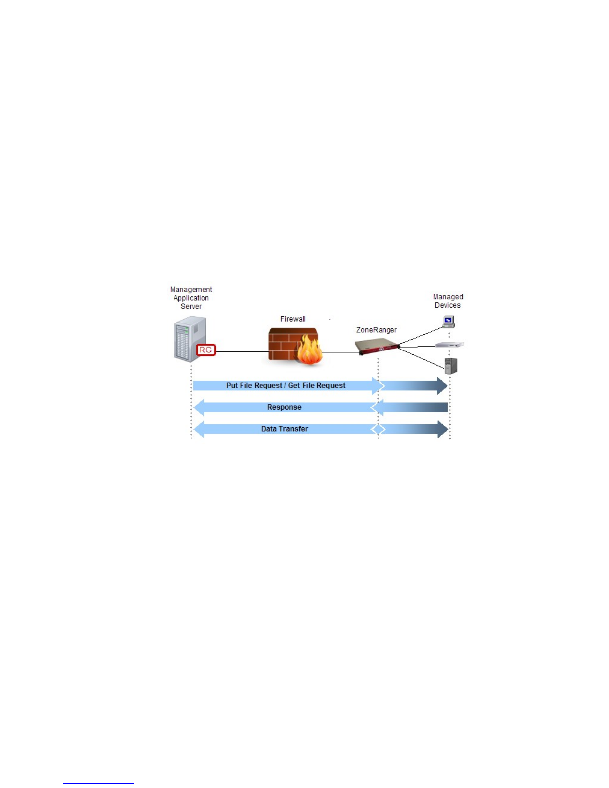
Chapter 21: FTP Proxy
The basic intent of the FTP protocol is to allow client applications to transfer files to/from a remote
server. The FTP protocol is based on TCP and separates control and data into separate TCP connections.
In cases where the client and server are separated by a firewall, this separation of control and data
connections creates a problem. While control connections are always directed at a well-known port, data
connections use dynamically assigned ports, making it difficult to configure the firewall to allow only
the needed ports. Making matters worse, the direction in which the data connection is initiated depends
on whether requested transfer mode is active or passive, making it difficult to implement a policy
preventing initiation of connections from less secure network zones to more secure network zones.
The ZoneRanger FTP proxy service provides an effective solution for these problems, acting as an
application-layer proxy firewall for FTP traffic, enabling FTP clients to exchange files with servers
located within firewall-partitioned networks.
The following figure provides a high-level overview of an FTP proxy transaction. Note that the
Management Application Server in this figure is acting as an FTP client, and one or more managed
devices may act as FTP servers.
Figure 21-1. ZoneRanger FTP Proxy
Note that the put file or get file requests and associated responses shown in this figure are exchanged via
the control connection, while the transfer of the actual file content takes place over a separate TCP data
connection. The ZoneRanger FTP proxy service carefully inspects all FTP control connection traffic,
and only those data connections that are matched with known outstanding transfer requests, are allowed
to pass.
The ZoneRanger FTP proxy feature supports all FTP protocol transactions defined in RFC 959,
including:
• Get File Request (from devices in a firewall-partitioned zone)
• Put File Request (to devices in a firewall-partitioned zone)
• List Directory Request
• Delete File Request
• Rename File Request
ZoneRanger 5.5 User's Guide
65
Page 66

In addition to supporting active and passive mode file transfers, the ZoneRanger FTP proxy feature
(Configuration > Inbound Proxy page TCP tab) also includes an optional active-to-passive conversion
feature, allowing an FTP client’s active mode transfer requests to be presented to clients as passive mode
requests, so that clients that only support active mode are able to exchange files with servers that only
support passive mode. The active-to-passive conversion feature is enabled on a per-ZoneRanger basis.
When this feature is enabled the ZoneRanger will present all FTP proxy requests to managed devices in
the form of passive requests, regardless of whether to FTP client’s request is active or passive.
In cases where the FTP servers reside in a less secure network than the FTP clients, enabling active-topassive conversion, where possible, is recommended from a security perspective, because it ensures that
all FTP data connections are originated by the ZoneRanger, rather than by the managed devices.
While the ZoneRanger FTP proxy service is able to mitigate a variety of risks associated with passing
FTP traffic between firewall-partitioned networks, it should be noted that the FTP protocol exchanges
user ID and password information over an unencrypted TCP connection, which results in a certain
amount of unavoidable risk. As a result, it is recommended that newer, more secure file transfer
protocols such as SCP and SFTP alternatives be used wherever possible. The ZoneRanger FTP proxy
service is recommended for use only in cases where the managed devices reside in a highly secure
network, or where FTP is the only solution available, given the management applications and/or
managed devices involved.
ZoneRanger 5.5 User's Guide
66
Page 67
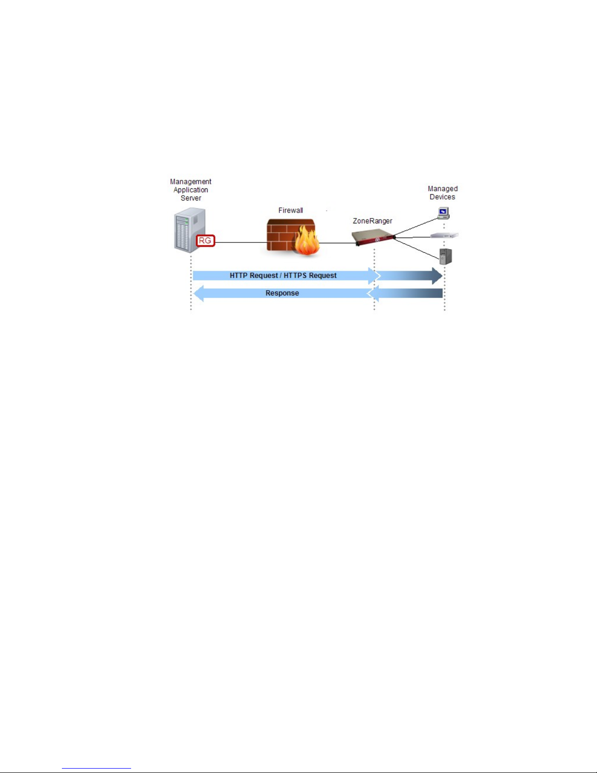
Chapter 22: HTTP/HTTPS Proxy
A Ranger Gateway and one or more joined ZoneRangers can provide an HTTP/HTTPS proxy service,
enabling access to web servers located in firewall-partitioned networks, without requiring the firewall to
be configured to pass HTTP or HTTPS.
The following figure provides a high-level overview of an HTTP/HTTPS proxy transaction. Note that
the Management Application Server in this figure is acting as a web browser, and one or more managed
devices may act as web servers.
Figure 22-1. ZoneRanger HTTP/HTTPS
In addition to using HTTP/HTTPS proxy to communicate with managed devices, the HTTP and HTTPS
proxy services can also be used to access the ZoneRanger web interface for joined ZoneRangers.
While the ZoneRanger is able to proxy both HTTP and HTTPS protocols, HTTPS will typically be the
preferred protocol for most applications, because the HTTP protocol may exchange user ID and
password information over an unencrypted TCP connection, and therefore is less secure. As a result,
HTTPS proxy is enabled by default and HTTP is disabled by default for managed devices.
Web browsers can access HTTP and HTTPS Proxy services in a variety of ways, as described in the
following sections.
GVI/RGVI
When using GVI or RGVI, the web browser sends HTTP or HTTPS requests intended for a
managed device to the actual address of the target device, or an address that can be uniquely
mapped to the target device. The management application server is configured with static routing
rules, so that traffic destined for devices located in firewall-partitioned networks is routed to a
virtual interface, which then forwards the traffic to the Ranger Gateway.
When the Ranger Gateway receives the initial TCP connection request for an HTTP or HTTPS
session, it will check the Proxy Access Control configuration to verify that the request should be
allowed, and to identify the proxy service to which the request should be forwarded. The Ranger
Gateway will then consult the Proxy Map service in order to identify a ZoneRanger that is able to
relay the request to the target device. The request is then forwarded to the selected ZoneRanger,
which in turn, establishes a TCP connection to the target device. Once this TCP connection is
established, the ZoneRanger will inform the Ranger Gateway, and the Ranger Gateway will
complete the establishment of the initial TCP connection (i.e. the connection between the web
browser and the Ranger Gateway). From this point on, the Ranger Gateway and selected
ZoneRanger will relay HTTP or HTTPS data between the web browser’s TCP connection to the
Ranger Gateway and the ZoneRanger’s TCP connection to the target device, until one of the
connections is disconnected.
ZoneRanger 5.5 User's Guide
67
Page 68

The primary advantage of GVI and RGVI is that the existence of the HTTP/HTTPS proxy is
completely transparent to the management application. Common routing mechanisms within the
underlying operating system are used to intercept traffic bound for devices in firewall-partitioned
networks, so there is no need to modify or reconfigure the management application in any way.
Another advantage is that the same mechanism can be used for other proxy services, such as ICMP
proxy, or SNMP proxy.
SOCKS
SOCKS is a standard protocol for generic TCP and UDP proxy services that can be used to redirect
management traffic from the management application to a SOCKS server integrated within the
Ranger Gateway. In order to use SOCKS, either the management application must include built-in
support for SOCKS, or generic SOCKS “shim” software must be installed on the management
application server. The shim software inserts itself between the management application and the
server’s TCP/IP stack, and redirects traffic for specified IP addresses and ports to a SOCKS server,
based on configuration information.
In order to access a managed device through HTTP or HTTPS proxy, a SOCKS-aware web browser
initially establishes a TCP connection to the SOCKS port (by default, 4855) on the Ranger
Gateway. After this connection is established, the client application sends a SOCKS connection
request to the Ranger Gateway, indicating the managed device and port to which the client would
like to connect.
The SOCKS server on the Ranger Gateway will check the Proxy Access Control configuration to
verify that the request should be allowed, and to identify the proxy service to which the request
should be forwarded. The Ranger Gateway will then consult the Proxy Map service in order to
identify a ZoneRanger that is able to proxy traffic to the target device, and to translate the target
address, if necessary, then forwards the connection request to the selected ZoneRanger, which
attempts to connect to the target device. If this connection is successfully established, the
ZoneRanger notifies the Ranger Gateway, which in turn notifies the web browser.
From this point, the Ranger Gateway and selected ZoneRanger simply relay data between the client
application’s TCP connection to the Ranger Gateway and the ZoneRanger’s TCP connection to the
target device, allowing the web browser and target device to exchange HTTP/HTTPS requests and
responses. The Ranger Gateway and ZoneRanger continue to relay data until one of the connections
is disconnected. Most web browsers support the SOCKS protocol.
As an example, the following steps would be used to configure Internet Explorer 6.0 to use the
SOCKS server on the Ranger Gateway (port 4855).
1. Select Internet Options… from the Tools menu and click the Connections tab. The
resulting dialog should be as shown in the following figure.
ZoneRanger 5.5 User's Guide
68
Page 69
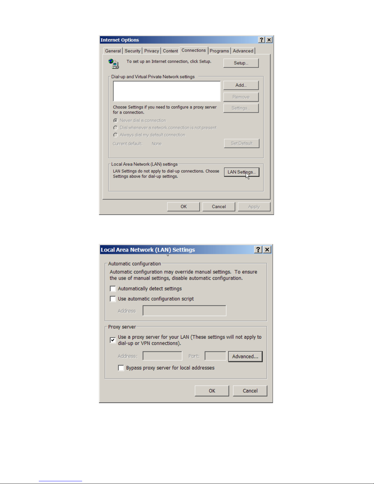
Figure 22-2. Internet Explorer ... Connections tab
2. Click the LAN Settings button. A dialog box will open as shown in the following figure.
Figure 22-3. Internet Explorer ... LAN Settings
3. Check the Use a proxy server for your LAN box, then click the Advanced… button. A
dialog box will open as shown in the following figure.
ZoneRanger 5.5 User's Guide
69
Page 70
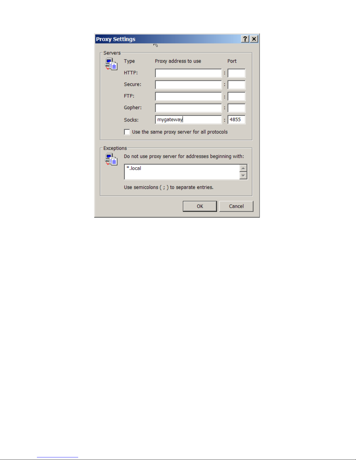
Figure 22-4. Internet Explorer ... Proxy Settings
4. Enter the IP address or hostname of the Ranger Gateway and the SOCKS server port in the
Socks row of the Servers table as shown in the figure. Note that the Use the same proxy
server for all protocols box should be left unchecked, and all of the other rows in the
Servers table should be left blank as shown in the figure.
5. Click OK in the three dialog boxes to save your changes.
Dedicated HTTP/HTTPS Ports
When a ZoneRanger is joined to a Ranger Gateway, the Ranger Gateway allocates dedicated ports
that can be used to access various services (for example, HTTP, HTTPS, SQL, Telnet, and SSH) on
the newly joined ZoneRanger.
You can use the listTcpPorts command on the Ranger Gateway command interface or the Ranger
Gateway Viewer to identify the ports that have been allocated for each ZoneRanger.
For example, the following figure shows the dedicated ports associated with a selected ZoneRanger
listed on the Information tab of the main window of the Ranger Gateway Viewer. Note that the
HTTP Port in this case is 20000 and the HTTPS Port is 20001.
ZoneRanger 5.5 User's Guide
70
Page 71
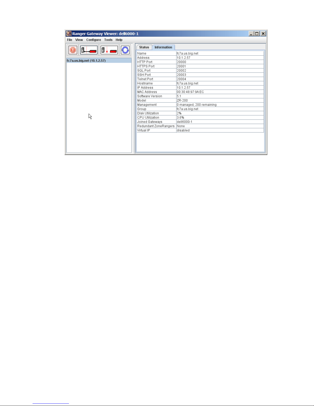
Figure 22-5. Ranger Gateway ... Information tab
A web browser can establish a proxy connection to a joined ZoneRanger simply by connecting to
the Ranger Gateway’s address, specifying the dedicated HTTP or HTTPS port associated with that
ZoneRanger as the destination port, as shown in the following figure.
ZoneRanger 5.5 User's Guide
71
Page 72
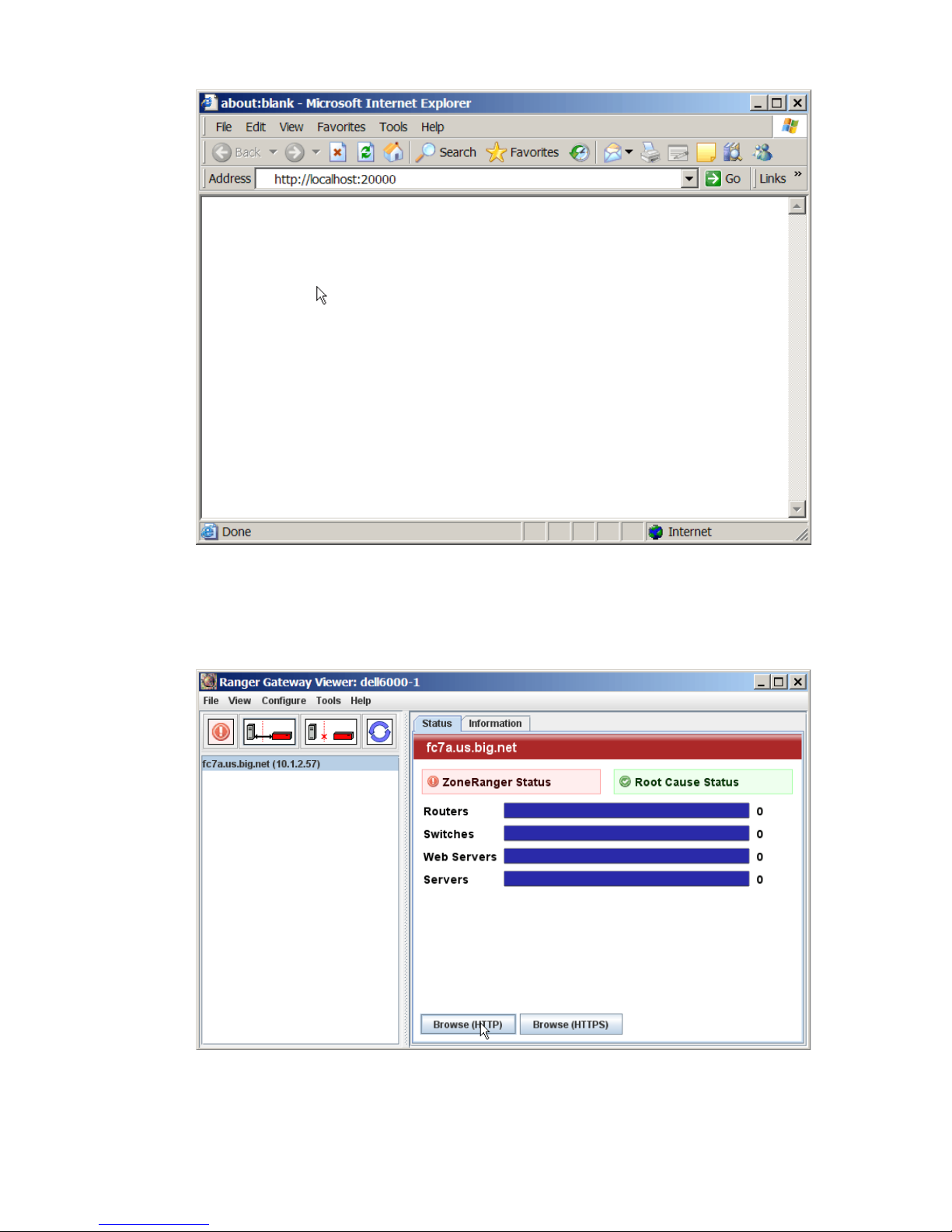
Figure 22-6. Ranger Gateway ... Local Port
As a shortcut, the user can automatically launch their default browser and browse via a dedicated
HTTP or HTTPS port to the web interface of the selected ZoneRanger by clicking the Browse
(HTTP) or Browse (HTTPS) buttons on the Status tab of the Ranger Gateway Viewer’s main
window as shown in the following figure.
Figure 22-7. Ranger Gateway Main Window
ZoneRanger 5.5 User's Guide
72
Page 73
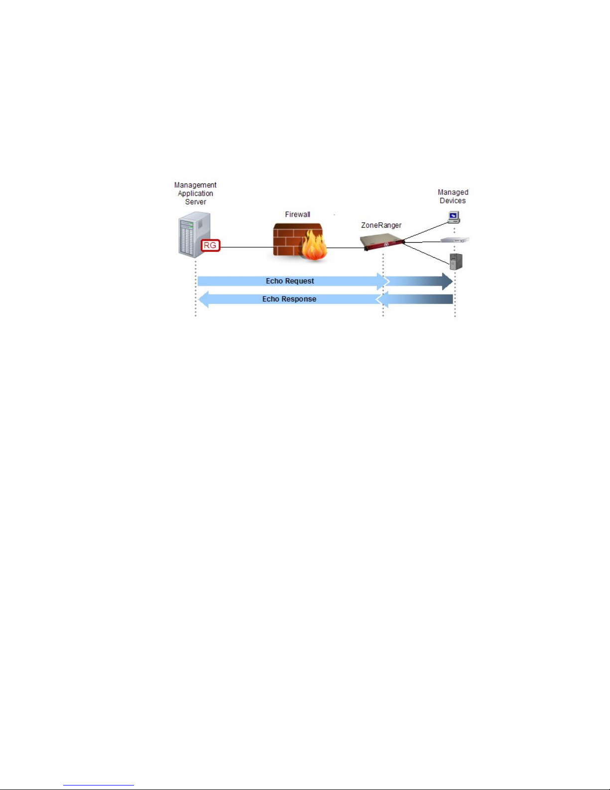
Chapter 23: ICMP Proxy
A Ranger Gateway and one or more joined ZoneRangers can provide an ICMP proxy service, enabling
management applications to send ICMP echo requests (a.k.a. “ping”) to devices in firewall-partitioned
networks (e.g. DMZs), and to receive associated ICMP echo responses, without requiring the firewall to
be configured to allow ICMP traffic. The ICMP proxy service will only proxy ICMP echo requests and
responses.
The following figure provides a high-level overview of an ICMP proxy transaction.
Figure 23-1. ZoneRanger ICMP Proxy
The basic steps of an ICMP proxy transaction are as follows:
1. A management application generates an ICMP echo request, intended for a specific managed
device.
2. The Ranger Gateway intercepts the ICMP echo request via the GVI or RGVI interface.
3. The Ranger Gateway checks the Proxy Access Control configuration to verify that the ICMP
echo request should be allowed, and to identify the proxy service to which the ICMP echo
request should be forwarded (i.e. ICMP Proxy).
4. The ICMP Proxy service in the Ranger Gateway consults with the Proxy Map service to select a
ZoneRanger that is able to relay the ICMP echo request to the target device, then forwards the
ICMP echo request to the selected ZoneRanger.
5. The ZoneRanger forwards the ICMP echo request to the managed device.
6. The managed device generates an ICMP echo response and sends it to the requesting
ZoneRanger.
7. The ZoneRanger forwards the ICMP echo response to the Ranger Gateway.
8. The Ranger Gateway forwards the ICMP echo response to the management application.
In order to use the ICMP proxy service, the GVI or RGVI service, as described in Chapter 7, on the
Ranger Gateway must be enabled, and configured to intercept traffic destined for managed devices
located in firewall-partitioned networks.
The ICMP proxy service can optionally be configured to perform proxy caching as described in Chapter
33.
ZoneRanger 5.5 User's Guide
73
Page 74
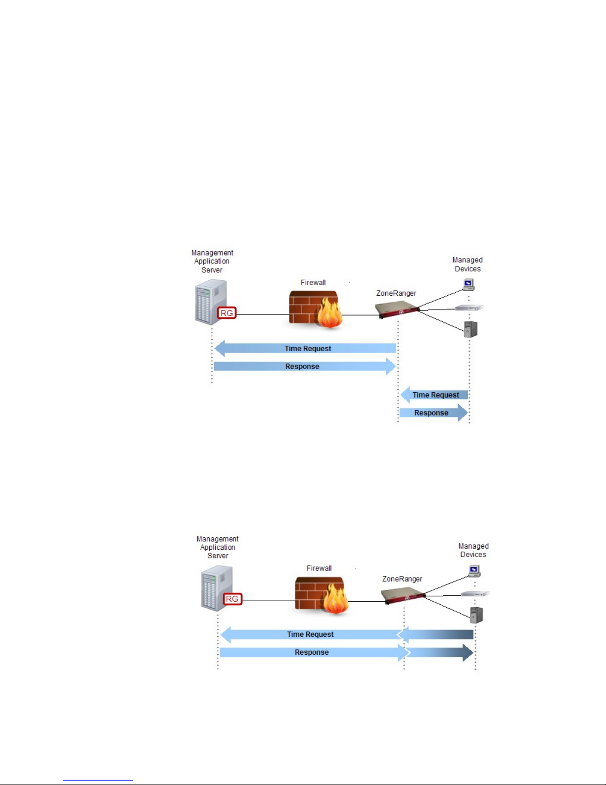
Chapter 24: NTP Proxy
The Network Time Protocol (NTP) allows network devices and servers to synchronize their clocks with
one or more centralized time servers, across a variable-latency network. In applications where time
synchronization across devices is important, the ability to administer time across a large number of
devices from a small number of centralized time servers using NTP is a significant advantage.
A ZoneRanger, joined to a Ranger Gateway, can provide an NTP proxy service, enabling devices in
firewall-partitioned networks to synchronize their clocks with NTP servers located in other network
zones, without requiring configuration of firewall rules to allow NTP traffic. ZoneRanger’s NTP proxy
service can be configured to operate in either of two modes:
1. The ZoneRanger can obtain its time from a centralized NTP server (either directly or via a
joined Ranger Gateway), and can act as a secondary time server, responding autonomously to
NTP requests from client devices, as illustrated in the following figure.
Figure 24-1. ZoneRanger NTP Proxy -- Mode 1
2. The ZoneRanger can act as straight NTP protocol proxy, inspecting NTP requests received from
client devices, relaying valid requests via a joined Ranger Gateway to a centralized timer
server, and relaying server responses back to the requesting clients, as illustrated in the
following figure.
Figure 24-2. ZoneRanger NTP Proxy -- Mode 2
ZoneRanger 5.5 User's Guide
74
Page 75

Configuring ZoneRanger to Act as a Secondary NTP Server
The following steps are required to configure ZoneRanger to act as a secondary NTP time server
and can be found on the web interface on the Configuration > System page Time tab:
1. The Time Synchronization Enabled option should be enabled.
2. The Server Type for time synchronization should be set to NTP.
3. If NTP authentication is required, a set of one or more (index, key) pairs should be
configured in the NTP Keys table. This set of (index, key) pairs may include:
a. Pairs that match the values configured on the NTP servers, as described in part “c” of
the following step.
b. Additional pairs that managed devices may use when authenticating NTP traffic
to/from the ZoneRanger.
4. A list of NTP time servers should be configured in the NTP Servers table. The following
information is required for each entry in the list:
a. The Ranger Gateway through which the ZoneRanger will access the NTP server. The
value “None (direct)” can be specified if the ZoneRanger should access the NTP server
directly.
b. The IP address or hostname of the NTP server.
c. The authentication (index, key) to be used when accessing the NTP server. The
selected (index, key) must match the configuration of the specified server. That is,
the set of (index, key) pairs configured on the specified server must include the
selected (index, key) pair.
5. The ZoneRanger Acts as NTP Server option should be enabled.
6. Optionally, the Authenticate Client Requests option may be enabled.
7. Managed devices should be configured to use the ZoneRanger as their NTP time server. For
high availability, multiple ZoneRangers configured to act as an NTP server can be deployed in
the same network. If the redundant ZoneRangers are configured with the virtual IP address
feature enabled, the configured NTP server list for each managed device can simply include the
virtual IP address. If the virtual IP address feature is not enabled, the configured NTP server list
for each managed device should include the specific address for each NTP-enabled
ZoneRanger.
Configuring ZoneRanger to Act as an NTP Proxy
The following steps are required to configure ZoneRanger to act as an NTP proxy and can be found
on the web interface on the Configuration > Inbound Proxy page NTP tab:
1. The ZoneRanger must be configured not to act as an NTP server. This can be accomplished in a
variety of ways:
a. Time Synchronization on the Configuration > System page Time tab can be disabled.
b. The Server Type for time synchronization can be set to a value other then NTP.
c. The ZoneRanger Acts as NTP Server option can be disabled.
2. A list of NTP time servers should be configured in the Proxy NTP Servers. The following
information is required for each entry in the list:
ZoneRanger 5.5 User's Guide
75
Page 76

a. The Ranger Gateway through which the ZoneRanger will access the NTP server. Note
that the option for the ZoneRanger to access an NTP server directly is not supported in
this case.
b. The IP address or hostname of the NTP Server.
3. Optionally, the Validate Authentication option may be enabled. If this option is enabled, a set
of (index, key) pairs must be configured in the Keys table. These values must match the
corresponding values configured on the NTP servers that were specified in the previous step. In
the case of NTP proxy, the managed device acting as an NTP client does not have any control
over which NTP server will be chosen to handle each request. As such, the table of (index,
key) values in the specified NTP servers must be identical, at least for the set of indexes that
the managed devices may use.
4. By default, when the ZoneRanger proxies a NTP proxy request through the joined Ranger
Gateway to the NTP server, the source of the NTP request will appear to the NTP server as if
the NTP client is the Ranger Gateway server and not the actual ZoneRanger managed device. It
is possible to configure the Ranger Gateway to spoof the source address in the NTP proxy
request to be that of the ZoneRanger managed device instead of the address of the Ranger
Gateway. To configure NTP proxy spoofing, either use the Ranger Gateway Viewer Configure
> Gateway Settings menu, NTP Proxy area or the configGateway command on the Ranger
Gateway.
Additional Note
If the Ranger Gateway is communicating with an NTP server installed on the same server using
GVI or on a different server using RGVI, it may be necessary to restart the NTP server after the
GVI service or RGVI client on that server are enabled. The startup procedure of some NTP servers
is to enumerate the IP addresses on a given server, and then to specifically bind a listener for each of
these addresses. Enabling GVI or starting an RGVI client effectively creates a new IP address,
associated with an underlying virtual point-to-point interface, and if this interface was not
configured at the point when the NTP server was started, the NTP server will be unaware of the
additional interface, and will not be able to receive NTP traffic from that interface. Where the
Ranger Gateway and an NTP server are co-located on the same server, it is recommended that the
server be configured to start the Ranger Gateway before starting the NTP server when the server
starts up. Similarly, where an RGVI client and an NTP server are co-located on the same server, it
is recommended that the server be configured to start the RGVI client before starting the NTP
server.
ZoneRanger 5.5 User's Guide
76
Page 77

Chapter 25: Polling
ZoneRanger has the capability to monitor managed devices for status changes. ZoneRanger supports the
following types of polling:
• ICMP polling (often called “ping”) to determine the status of IP interfaces
• SNMP querying of ifTable information (ifOperStatus) of SNMP enabled nodes to
determine the status of individual interfaces
• TCP polling of TCP ports on nodes to determine the status of processes listening on the ports
The Configuration > Polling page on the ZoneRanger provides the interface for polling configuration.
By default, when a device is discovered, it is automatically configured to be polled for status changes.
This behavior may be changed on the Configuration > Discovery page Options tab by unchecking
Auto managing newly discovered nodes.
ICMP Polling
ZoneRanger uses ICMP polling to monitor the status of IP interfaces. By default, ZoneRanger polls
interfaces on managed devices every 5 minutes (300 seconds). Using the Configuration > Polling
page Interface Settings tab, different polling rates as well as ICMP timeouts and retries may be
configured for nodes, specific IP interfaces, or groups of IP interfaces.
Whether or not ICMP polling is enabled or disabled for a particular IP interface may be configured
on the Configuration > Polling page Enable/Disable tab. By choosing the appropriate device in
the list, ICMP polling for each IP interface may be disabled by setting Poll Interface to None.
When ZoneRanger determines the status of an IP interface has changed, a tscZRIfUp or
tscZRIfDown SNMP trap is generated as appropriate. If a device is determined to have changed
state, a tscZRNodeUp or tscZRNodeDown trap will be generated. If at least one interface of a
device whose previous status was Up is determined to be Down, a tscZRNodeMarginal trap will be
generated.
ICMP Latency
As the ZoneRanger ICMP polls IP interfaces, the polling service caches the last ICMP round-trip
time for each IP interface. This value may be retrieved for all IP addresses or specific IP addresses
using the viewIcmpLatency command from a joined Ranger Gateway. The polling service only
retains the last ICMP latency measurement for each polled IP interface.
SNMP Polling
For those interfaces which do not have an IP address, ZoneRanger can be configured to use SNMP
polling to monitor the status. The SNMP status of an interface is determined by the SNMP querying
of ifTable information (ifOperStatus) of SNMP enabled nodes. By default, ZoneRanger
does NOT automatically configure any interfaces to use SNMP polling. When SNMP polling is
configured, ZoneRanger polls those interfaces on managed devices every 5 minutes (300 seconds).
Using the Configuration > Polling page Interface Settings tab, different polling rates for nodes,
specific interfaces, or groups of interfaces may be configured. If the interface is an SNMP interface
without an IP address, the node name in the database should be used as the pattern.
Whether or not SNMP polling is enabled or disabled for a particular interface may be configured on
the Configuration > Polling page Enable/Disable tab. By choosing the appropriate device in the
list, SNMP polling for each interface may be enabled by setting Poll Interface to SNMP.
ZoneRanger 5.5 User's Guide
77
Page 78

If the SNMP option under Poll Interface is unavailable for the interfaces on a device (i.e. there is
no ifIndex listed), that means the device did not respond to an SNMP request when it was
discovered. If the device is configured to support SNMP, verify the settings on the Configuration >
SNMP page are correct for this device. Then use the Diagnostics > SNMP walk page to test
whether or not ZoneRanger can use SNMP to query the device. Once ZoneRanger can successfully
make SNMP requests to the device, the device needs to be rediscovered using the Configuration >
Discovery page.
When ZoneRanger determines the status of an interface has changed, a tscZRIfUp or tscZRIfDown
SNMP trap is generated as appropriate. If a device is determined to have changed state, a
tscZRNodeUp or tscZRNodeDown trap will be generated. If at least one interface of a device
whose previous status was Up is determined to be Down, a tscZRNodeMarginal trap will be
generated.
TCP Polling
ZoneRanger uses TCP polling of TCP ports on nodes to determine the status of processes listening
on those TCP ports. By default, ZoneRanger polls TCP ports on managed devices every 5 minutes
(300 seconds). Use the Configuration > Polling page TCP Settings tab to configure different
polling rates for an individual TCP Port as well as modifying the default TCP port polling rate.
Polling for a particular TCP port may be enabled or disabled using the Polling Enabled column on
the Configuration > Polling page TCP Settings tab. When devices are discovered, the TCP ports
listed on this tab will automatically be polled. If a Polling Enabled checkbox is unchecked, polling
for the corresponding TCP port is disabled for all nodes, regardless of the per-node Poll TCP
settings.
TCP port status propagation for specific services can be enabled or disabled for all nodes. If status
propagation is enabled, TCP port status effects the overall status of nodes. Thus, if a TCP port does
not, the TCP port will be in the Down state and the node will be in the Marginal state. When
ZoneRanger determines the status of an TCP port has changed, a tscZRTcpUp, tscZRTcpBusy,
tscZRTcpRefused, or tscZRTcpTimout SNMP trap is generated as appropriate.
All of the TCP ports listed on the Configuration > Polling page TCP Settings tab, are configured
on the Configuration > Discovery page TCP Ports tab. If a TCP is added or removed on the
Configuration > Discovery page TCP Ports tab, that TCP port will be added or removed from the
Configuration > Polling page TCP Settings tab.
ZoneRanger 5.5 User's Guide
78
Page 79

Chapter 26: Root Cause
Though the use of a sophisticated root cause analysis service, ZoneRanger will automatically determine
the root cause of a device outage. Depending on the network topology, a problem with one device, such
as a router or switch, can affect status polling results for multiple devices. To address this problem, when
ZoneRanger is triggered by status polling failures as described in Chapter 24, the root cause service
determines which device is the root cause of the problem, and which devices are impacted by the root
cause device.
The root cause service divides root cause analysis into two categories: IP (related to interface status
polling failures) and TCP (related to TCP status polling failures). The Configuration > Root Cause
page IP tab is used to configure the reporting of IP root causes and the Configuration > Root Cause
page TCP tab is used to configure reporting TCP root causes.
After the polling service determines an IP interface has failed a status poll, the root cause service will
enter a verification period to determine if the IP interface is no longer replying or if it was a transitory
outage. The verification time period is configured on the Configuration > Root Cause page IP tab
from the Advanced button. The default is to verify an outage using four ICMP requests over a two
minute period.
Once the device is verified to have failed, a tscZRVerifyDown SNMP trap is generated. Then once the
root cause is determined, the tscZRSourceDown SNMP trap is generated indicating the root cause of the
outage. Using the Configuration > Root Cause page IP tab, ZoneRanger can be configured to send an
email indicating the root cause either through a joined Ranger Gateway or directly from the
ZoneRanger.
If the polling service determines additional IP devices fail to respond, whose outage was caused by a
root cause device, a tscZRInferredDown SNMP trap will be generated indicating this device is impacted
by a root cause outage. The list of current root causes can be displayed using the View > Root Causes
page on the ZoneRanger.
When a root cause device is successfully polled by the polling service, the root cause service verifies the
device is responding and generates a tscZRVerifyUp SNMP trap. A tscZRSourceUp SNMP trap and
optional email, if configured, are then generated indicating the root cause outage has been restored.
The root cause service describes root causes outages in terms of entities which are IP, TCP, or cloud.
The IP entity refers to an IP address. The TCP entity refers to a TCP port. The cloud entity refers to an
area of the network which the ZoneRanger could not determine any specific IP addressable information.
One example of a cloud is a dumb network hub.
ZoneRanger 5.5 User's Guide
79
Page 80
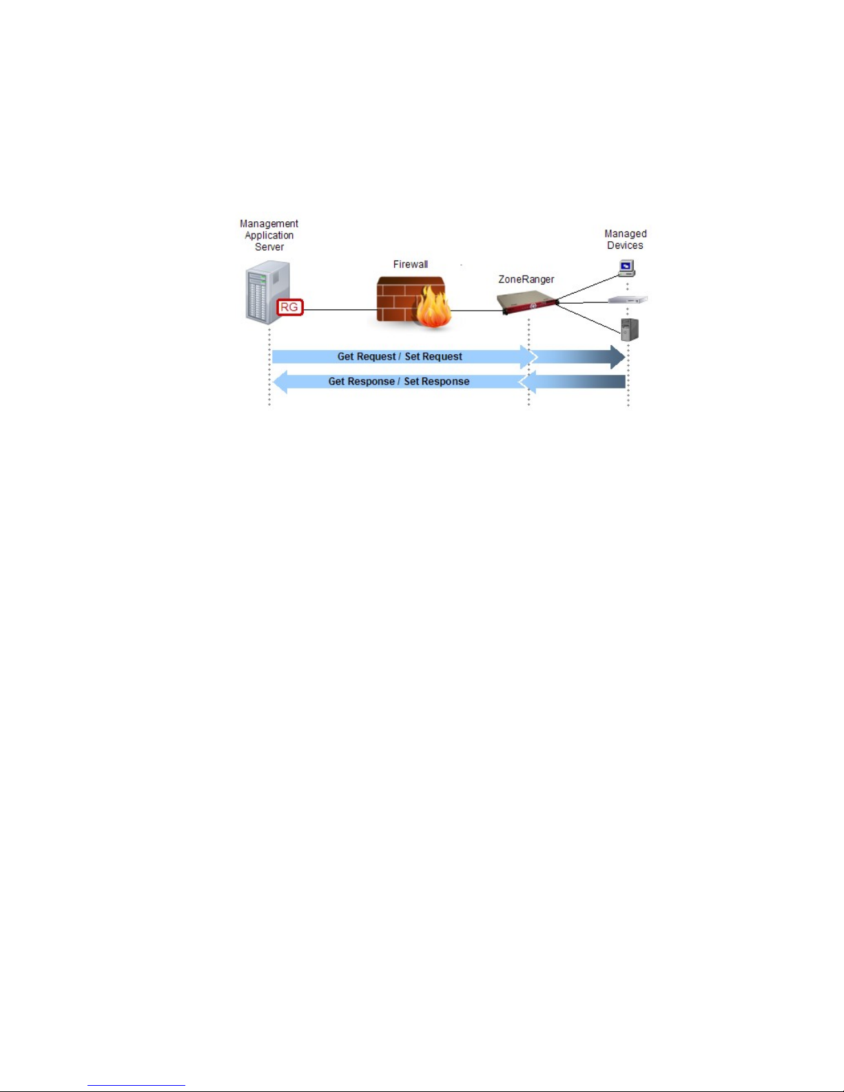
Chapter 27: SNMP Proxy
A Ranger Gateway and one or more joined ZoneRangers can provide an SNMP proxy service, enabling
management applications to have SNMP access to devices in firewall-partitioned networks (e.g. DMZs)
without requiring the firewall to be configured to allow SNMP traffic.
The following figure provides a high-level overview of an SNMP proxy transaction.
Figure 27-1. ZoneRanger SNMP Proxy
The basic steps of an SNMP proxy transaction are as follows:
1. A management application generates an SNMP Get or SNMP Set request, intended for a
specific managed device.
2. The Ranger Gateway receives/intercepts the request.
3. The Ranger Gateway checks the Proxy Access Control configuration to verify that the request
should be allowed, and to identify the proxy service to which the request should be forwarded
(i.e. SNMP Proxy).
4. The SNMP Proxy service in the Ranger Gateway consults with the Proxy Map service in order
to select a ZoneRanger that is able to relay the request to the target device.
5. The ZoneRanger forwards the request to the target device.
6. The target device generates a response and sends it to the requesting ZoneRanger.
7. The ZoneRanger forwards the response to the Ranger Gateway.
8. The Ranger Gateway forwards the response to the management application.
Management applications can access the SNMP Proxy service in a variety of ways, as described in the
following sections.
GVI/RGVI
When using GVI or RGVI, the management application sends SNMP requests intended for a
managed device to the actual address of the target device, or an address that can be uniquely
mapped to the target device. The management application server is configured with static routing
rules, so that traffic destined for devices located in firewall-partitioned networks is routed to a
virtual interface, which then forwards the traffic to the Ranger Gateway.
Consider the network example in the following figure. Two DMZ’s are shown. The first DMZ has
one ZoneRanger (ZR-1) and the second one has two (ZR-2, ZR-3). The IP addresses in the two
DMZ’s do not overlap.
ZoneRanger 5.5 User's Guide
80
Page 81
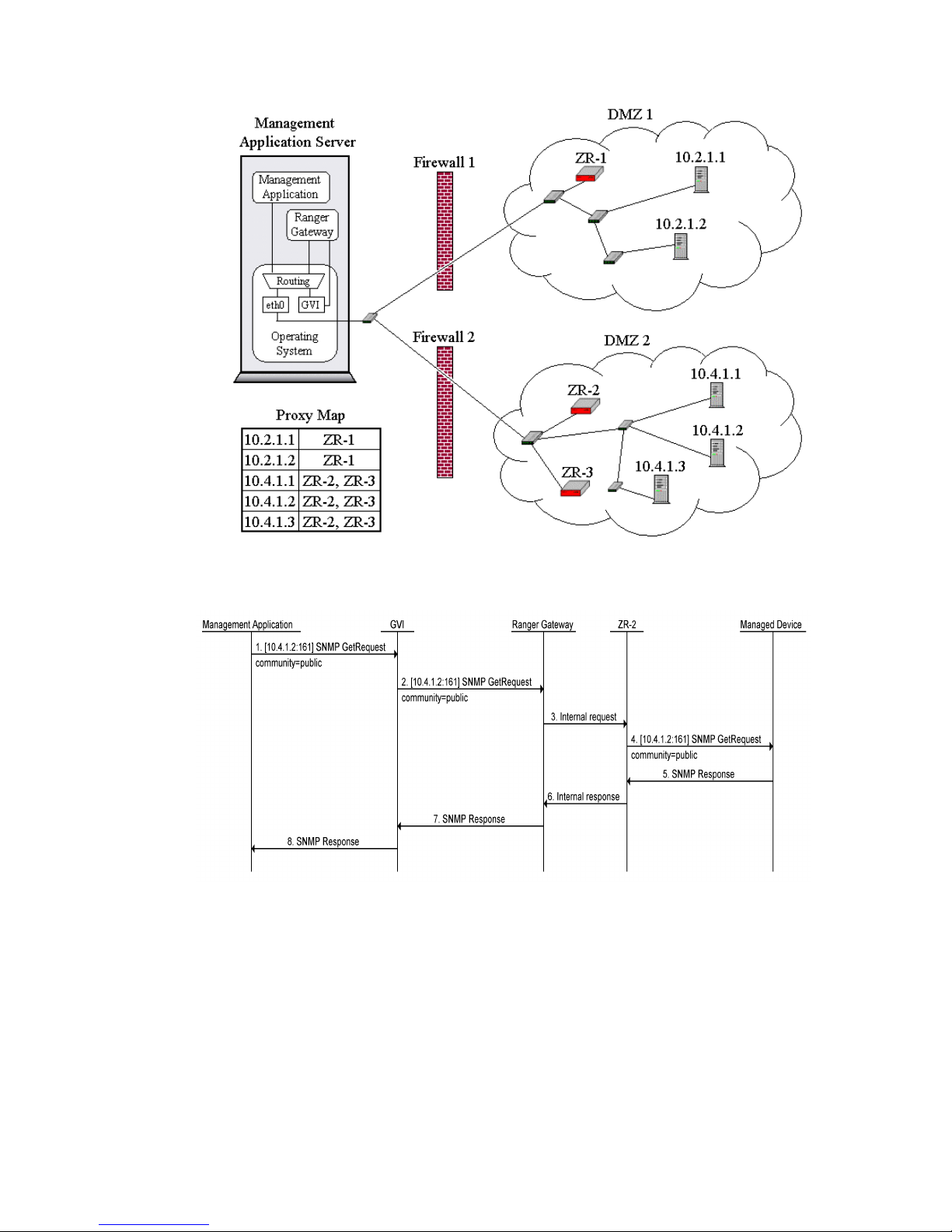
Figure 27-2. ZoneRanger SNMP Proxy with GVI
The messaging flow for an SNMP proxy request using GVI is illustrated in the following figure.
Note the following from this example:
• The management application requests that a UDP datagram containing the SNMP
GetRequest message be sent to the address of the target device (10.4.1.2) [1].
• The routing table in the management application server is preconfigured to route traffic
destined for the 10.4.1.2 address to the GVI driver.
• The GVI driver forwards the request to the Ranger Gateway [2], which checks the Proxy
Access Control configuration to verify that the request should be allowed and to identify
the proxy service to which the request should be forwarded (i.e. SNMP Proxy).
ZoneRanger 5.5 User's Guide
81
Page 82

• The SNMP Proxy service consults the Proxy Map service in the Ranger Gateway to
determine the list of ZoneRangers that manage the target device (ZR-2, and ZR-3). One of
the ZoneRangers (ZR-2) is selected, and the request is forwarded to the selected
ZoneRanger [3].
• The selected ZoneRanger forwards the request to the target device [4].
• The target device replies back to the ZoneRanger [5], which relays the response to the
Ranger Gateway [6]. The SNMP Proxy service relays the response to the GVI driver [7].
• The GVI driver forwards the response to the management application [8].
The primary advantage of GVI and RGVI is that the existence of the SNMP proxy is completely
transparent to the management application. Common routing mechanisms within the underlying
operating system are used to intercept traffic bound for devices in firewall-partitioned networks, so
there is no need to modify or reconfigure the management application in any way. Another
advantage is that the same mechanism can be used for other proxy services, such as ICMP proxy, or
TCP proxy.
SOCKS
SOCKS is a standard protocol for generic TCP and UDP proxy services that can be used to redirect
management traffic from the management application to a SOCKS server integrated within the
Ranger Gateway. In order to use SOCKS, either the management application must include built-in
support for SOCKS, or generic SOCKS “shim” software must be installed on the management
application server. The shim software inserts itself between the management application and the
server’s TCP/IP stack, and redirects traffic for specified IP addresses and ports to a SOCKS server,
based on configuration information.
When using the SOCKS mechanism, the management application sends SNMP requests intended
for a managed device to the actual address of the target device, or an address that can be uniquely
mapped to the target device. The built-in SOCKS client or the SOCKS shim redirects these requests
to the SOCKS server integrated within the Ranger Gateway.
ZoneRanger 5.5 User's Guide
82
Page 83
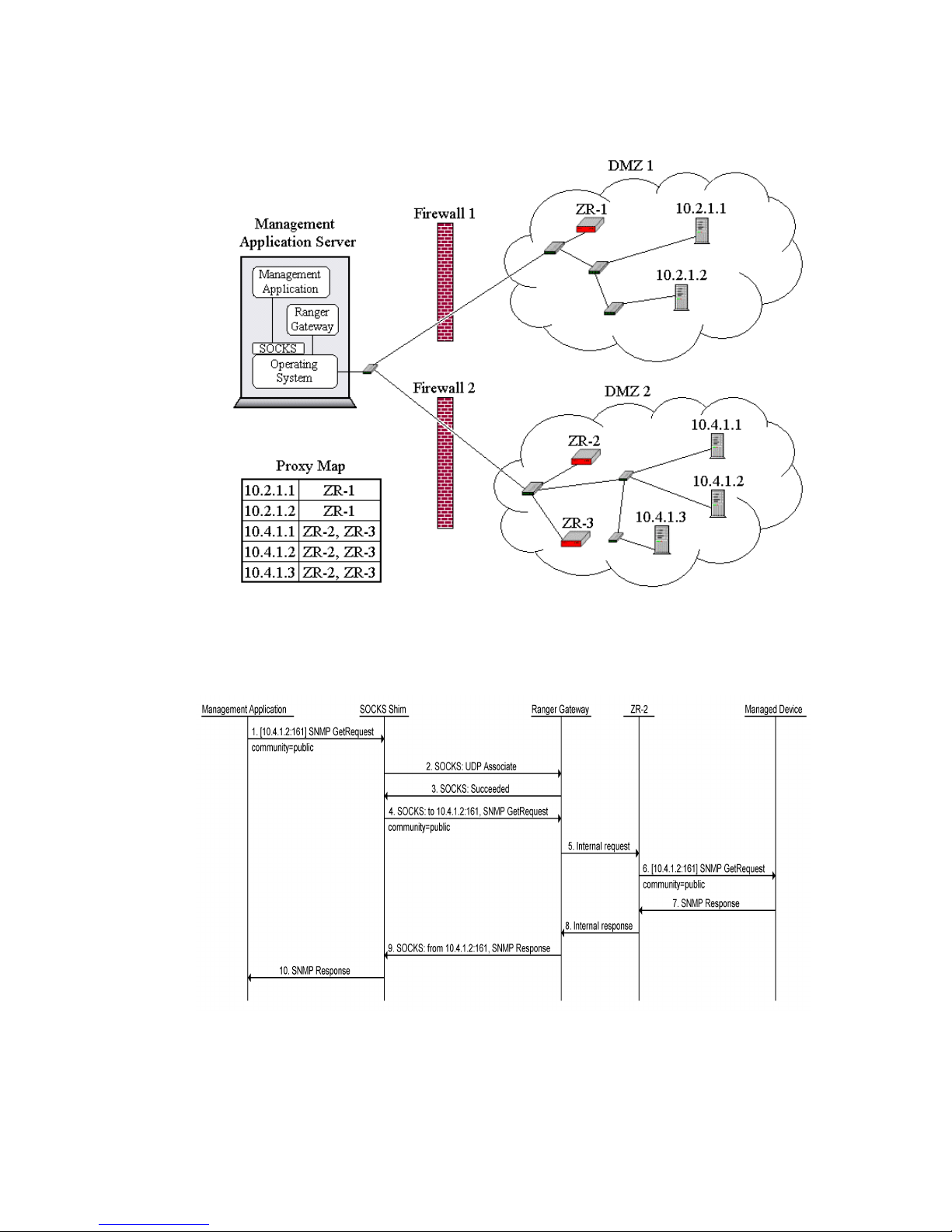
The following figure shows a SOCKS shim inserted between the management application and the
operating system.
Figure 27-3. ZoneRanger SNMP Proxy with SOCKS
The messaging flow for an SNMP proxy request using a SOCKS shim is illustrated in the following
figure.
Note the following from this example:
• The management application requests that a UDP datagram containing the SNMP Get
request message be sent to the address of the target device (10.4.1.2) [1].
ZoneRanger 5.5 User's Guide
83
Page 84

• The SOCKS shim intercepts the request, performs a SOCKS protocol handshake with the
SOCKS server in the Ranger Gateway, to establish a “UDP association” [2, 3], then
forwards the SNMP request, to the SOCKS server, along with a header indicating that the
datagram is intended for address 10.4.1.2 [4].
• The SOCKS server in the Ranger Gateway checks the Proxy Access Control configuration
to verify that the request should be allowed and to identify the proxy service to which the
request should be forwarded (i.e. SNMP Proxy).
• The SNMP Proxy service consults the Proxy Map service to determine the list of
ZoneRangers that manage the target device (ZR-2, and ZR-3). One of the ZoneRangers
(ZR-2) is selected, and the request is forwarded to the selected ZoneRanger [5].
• The selected ZoneRanger forwards the request to the target device [6].
• The target device replies back to the ZoneRanger [7], which relays the response to the
Ranger Gateway [8]. The SNMP Proxy service relays the response to the SOCKS server,
which forwards the response to the SOCKS shim along with a header indicating that the
response was received from 10.4.1.2 [9].
• The SOCKS shim forwards the response to the management application [10].
One advantage of SOCKS over GVI/RGVI is that it is typically possible to configure the SOCKS
client to route traffic for certain ports to the Ranger Gateway, while traffic destined for other ports is
routed normally. In addition, some SOCKS clients can be configured to only intercept traffic sent
from specified applications. A disadvantage of SOCKS is that many management applications do
not provide built-in support for SOCKS and reliable SOCKS shims may not be available for the
operating system being used. In these cases, an alternative SNMP proxy access mechanism will
need to be selected.
IP Address Aliasing
Most operating systems provide a means to associate multiple IP addresses with each network
interface (i.e. a primary address, and one or more “aliases”). If IP address aliases, corresponding to
managed devices located in firewall-partitioned networks, are defined on the management
application server, all traffic generated by the management application and destined for these
devices will be routed as local traffic to the interface where the IP address aliases have been defined.
If an SNMP proxy port has been configured, the SNMP Proxy service on the Ranger Gateway will
listen on that port for requests destined for any of these IP addresses. As a result, when a
management application sends an SNMP request intended for a managed device to one of the
configured alias addresses, with the destination port set to the configured SNMP proxy port, the
Ranger Gateway will receive the request.
If the management application and the Ranger Gateway software have been installed on the same
server, the IP address aliases can usually be added to the server’s loopback interface. In such cases,
it may be possible to configure the IP address aliases for managed devices to be the same as the
actual IP addresses of those devices. If the management application and the Ranger Gateway
software have been installed on different servers, the IP address aliases must be added to an
appropriate network interface on the Ranger Gateway server, and static routes will need to be
defined on the management application server to ensure that SNMP requests are routed to the
Ranger Gateway server.
ZoneRanger 5.5 User's Guide
84
Page 85
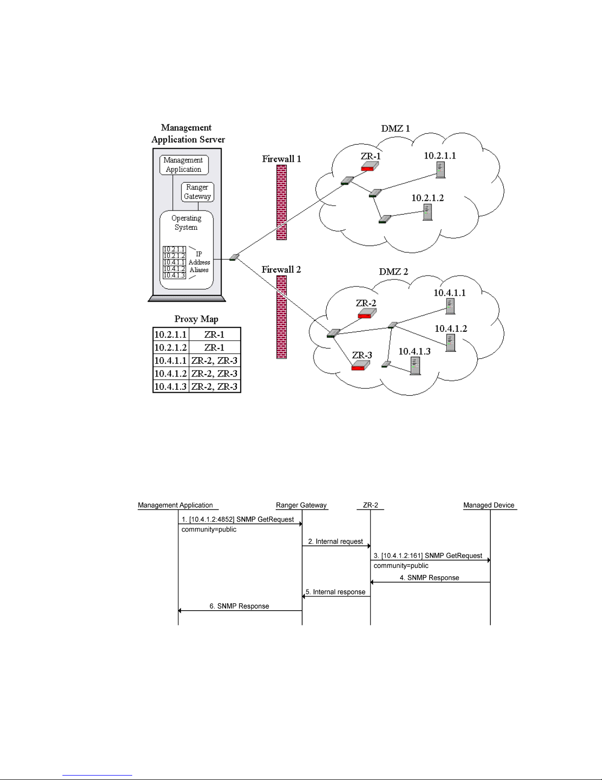
Consider the network example in the following figure. In this example, the management application
and the Ranger Gateway have been installed on the same server. Two DMZ’s are shown. The first
DMZ has one ZoneRanger (ZR-1) and the second one has two (ZR-2, ZR-3). The IP addresses in
the two DMZ’s do not overlap.
Figure 27-4. ZoneRanger SNMP Proxy with IP Aliasing
In order to manage this network, addresses 10.2.1.1, 10.2.1.2, 10.4.1.1, 10.4.1.2, and 10.4.1.3 would
be configured as IP address aliases on the management application server, corresponding to the five
managed devices, and the Proxy Map service in the Ranger Gateway would be configured as shown
in the figure. An example of the messaging flow for an SNMP proxy request is shown in the
following figure.
Note the following from this example:
ZoneRanger 5.5 User's Guide
85
Page 86

• The management application requests that a UDP datagram containing the SNMP Get
request message be sent to the address of the target device (10.4.1.2), using the destination
SNMP proxy port [1]. Assuming that the specified destination IP address has been defined
as an IP address alias on the management application server, the request will be delivered
to the SNMP Proxy service within the Ranger Gateway.
• The SNMP Proxy service in the Ranger Gateway will check the Proxy Access Control
configuration to verify that the request should be allowed, then will consult the Proxy Map
service to determine the list of ZoneRangers that manage the target device (ZR-2, and ZR-
3). One of the ZoneRangers (ZR-2) is selected, and the request is forwarded to the selected
ZoneRanger [2].
• The selected ZoneRanger forwards the request to the target device [3].
• The target device replies back to the ZoneRanger [4], which relays the response to the
Ranger Gateway [5].
• The Ranger Gateway forwards the response to the management application [6].
In some cases it may be necessary to configure the SNMP proxy service to use a non-standard port
value in order to avoid conflict with an SNMP agent on the Ranger Gateway server that may be
listening on port 161. The port that the ZoneRanger will use to present the request to the managed
device can be configured on a per-device basis. This allows different managed devices in the same
firewall-partitioned network to listen for SNMP requests on different ports. By default, the
ZoneRanger will forward SNMP requests to destination port 161.
IP address aliasing can be used on all operating systems where the Ranger Gateway software is
supported. The main disadvantage of the IP address aliasing technique is the administrative effort
required to add and maintain IP address aliases for all managed devices on the Ranger Gateway
server. Another concern is that operating systems may limit the number of IP address aliases that
can be defined. As a result, this technique may not be able to support the required number of
managed devices for some applications.
Community String Conventions
In all of the previously described mechanisms, the Ranger Gateway determines the address of the
target device for each SNMP request based on the address to which the management application
sent the request. An alternative is to configure the management application to send the SNMP
request to an arbitrary IP address on the Ranger Gateway server, and for the SNMP Proxy service
within the Ranger Gateway to determine the target device address based on additional information
embedded into the SNMP request’s community string, according to specified conventions. For
example, the following community string format can be used:
community@ZoneRanger@device
where community is the actual community string that the target device is expecting (e.g. public),
ZoneRanger is the name or IP address of a ZoneRanger that is managing the target device, and
device is the name or IP address of the target device. In this case, the Ranger Gateway would
extract the ZoneRanger and device values from the community string, and would forward the
request to the specified ZoneRanger. The ZoneRanger would then send the request to the target
device. Note that the ZoneRanger and device values are removed before the request is
forwarded to the target device, so the target device only sees the community value that it is
expecting.
ZoneRanger 5.5 User's Guide
86
Page 87
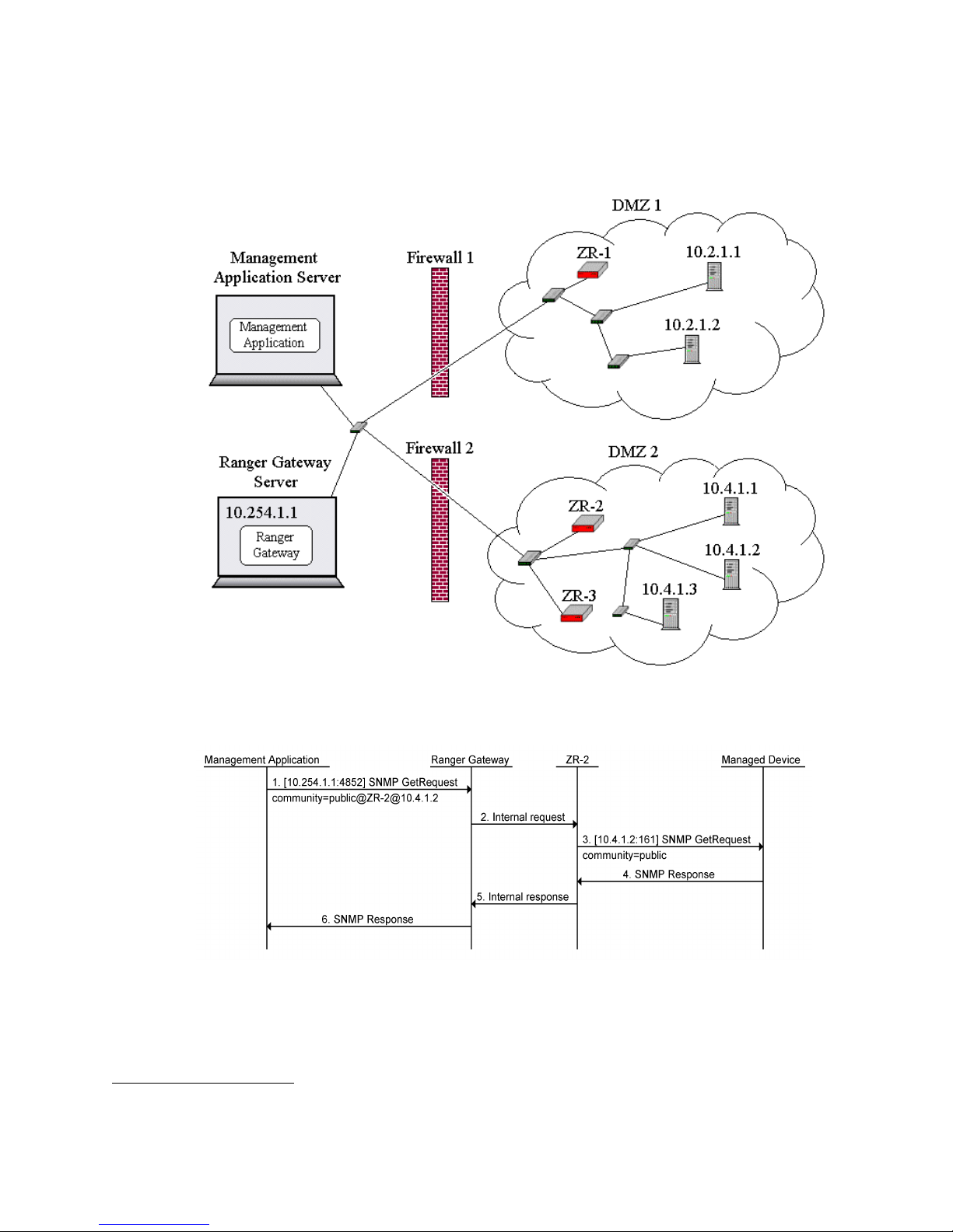
Consider the network example in the following figure. In this example, the management application
and the Ranger Gateway have been installed on different servers9. Two DMZ’s are shown. The first
DMZ has one ZoneRanger (ZR-1) and the second one has two (ZR-2, ZR-3). The IP addresses in
the two DMZ’s do not overlap. The IP address of the Ranger Gateway Server is 10.254.1.1.
Figure 27-5. ZoneRanger SNMP Proxy with Community String Conventions
An example of the messaging flow for an SNMP proxy request is shown in the following figure.
9
The community string conventions mechanism can also be used in cases where the Ranger Gateway
is installed on the management application server. In such cases, the management application would
need to send SNMP requests to a local IP address.
ZoneRanger 5.5 User's Guide
87
Page 88

Note the following from this example:
• The management application directs the SNMP request to the Ranger Gateway’s IP address
(10.254.1.1), using the SNMP proxy port [1]. The ZoneRanger to which the request should
be forwarded (ZR-2), and the target device’s actual IP address (10.4.1.2) are embedded in
the community string, along with the community string value that the target device expects
(i.e. public).
• The SNMP Proxy service in the Ranger Gateway receives the request, parses the
community string, verifies that the request should be allowed, then forwards the request to
the specified ZoneRanger [2].
• The ZoneRanger forwards the request to the target device [3], with the ZoneRanger and
device portions of the community string removed.
• The target device replies back to the ZoneRanger [4], which relays the response to the
Ranger Gateway [5].
• The Ranger Gateway forwards the response to the management application [6].
The SNMP Proxy service can be configured to use different community string formats. The
following formats are supported:
1. community@ZoneRanger@device
2. device@ZoneRanger@community
3. community@device
4. device@community
5. community
Formats 1 and 2 require management applications to specify the ZoneRanger (or ZoneRanger
group) that will relay the SNMP request to the target device. When using grouping, the
ZoneRanger field in the community string can be replaced with a group name that identifies a
group of ZoneRangers, and the SNMP Proxy service in the Ranger Gateway will automatically
select a ZoneRanger from this group to relay the request. The only difference between formats 1 and
2 is the order of the fields. The ability to configure the SNMP Proxy service to use different field
orders has been provided in order to handle situations where management applications and managed
devices are using their own community string prefix or suffix conventions.
Formats 3 and 4 do not require the management application to specify a ZoneRanger. Instead, the
SNMP Proxy service consults the Proxy Map service, in order to identify a ZoneRanger that is able
to relay traffic to the target device, and then forwards the SNMP request to the selected ZoneRanger.
The only difference between formats 3 and 4 is the order of the fields. The ability to use different
field orders has been provided in case management applications and managed devices are using
their own community string prefix or suffix conventions.
When the Proxy Map service is used, the responsibility for identifying the ZoneRanger to relay each
request is essentially moved from the management application to the Ranger Gateway. The
advantages of this approach are:
• Associations between ZoneRangers and DMZ devices, and any required address
translations for DMZ devices (e.g. if NAT is in effect) are configured in one place, and can
be shared by multiple proxy services across multiple management applications.
• The Proxy Map service can be configured to balance proxy requests across a set of
ZoneRanger candidates, resulting in a more even distribution of proxy traffic in situations
where DMZ devices are being managed by multiple ZoneRangers.
ZoneRanger 5.5 User's Guide
88
Page 89
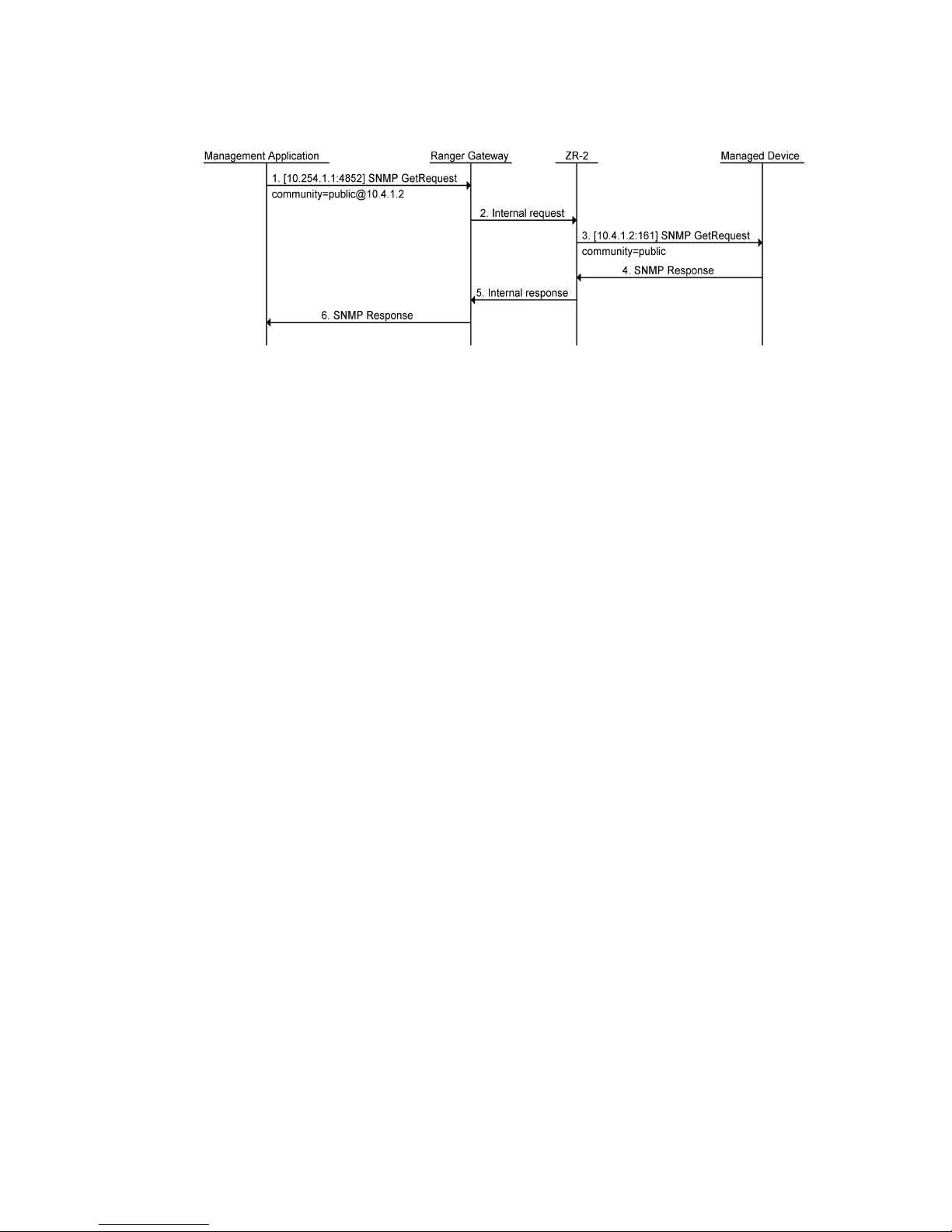
The following figure shows a message flow example, based on the previous sample network, using
the community@device convention.
Note the following from this example:
• The management application directs the SNMP request to the Ranger Gateway’s IP address
(10.254.1.1), using the SNMP proxy port [1]. The target device’s actual IP address
(10.4.1.2) is embedded in the community string, along with the community string value
that the target device expects (e.g. public).
• The SNMP Proxy service verifies that the request should be allowed, then consults the
Proxy Map service in the Ranger Gateway to determine the list of ZoneRangers that
manage the target device (ZR-2, and ZR-3). One of the ZoneRangers (ZR-2) is selected,
and the request is forwarded to the selected ZoneRanger [2].
• The selected ZoneRanger uses the actual IP address of the target device (10.4.1.2) to
forward the request to the target device [3], with the device portion of the community
string removed.
• The target device replies back to the ZoneRanger [4], which relays the response to the
Ranger Gateway [5].
• The Ranger Gateway forwards the response to the management application [6].
Format 5 implies that no special information is embedded in the community string, and is used in
conjunction with the IP address aliasing mechanism.
In some cases it may be necessary to configure the SNMP proxy service to use a non-standard port
value in order to avoid conflict with an SNMP agent on the Ranger Gateway server that may be
listening on port 161. The port that the ZoneRanger will use to present the request to the managed
device can be configured on a per-device basis. This allows different managed devices in the same
firewall-partitioned network to listen for SNMP requests on different ports. By default, the
ZoneRanger will forward SNMP requests to destination port 161. When community string
conventions are being used, the management application can optionally override the configured port
for a given device, by adding “:port” to the device part of the community string, where port
is the desired port number.
When community string conventions are used, a simplified form of Proxy Access Control is used to
determine whether or not requests should be allowed. Instead of using the portMap and portConfig
tables, as described in Chapter 14, the SNMP Proxy service simply verifies that the source address
associated with the request matches the configured SNMP proxy client address. The SNMP proxy
client address can be configured using the Ranger Gateway Viewer or by using the
configGateway command.
ZoneRanger 5.5 User's Guide
89
Page 90
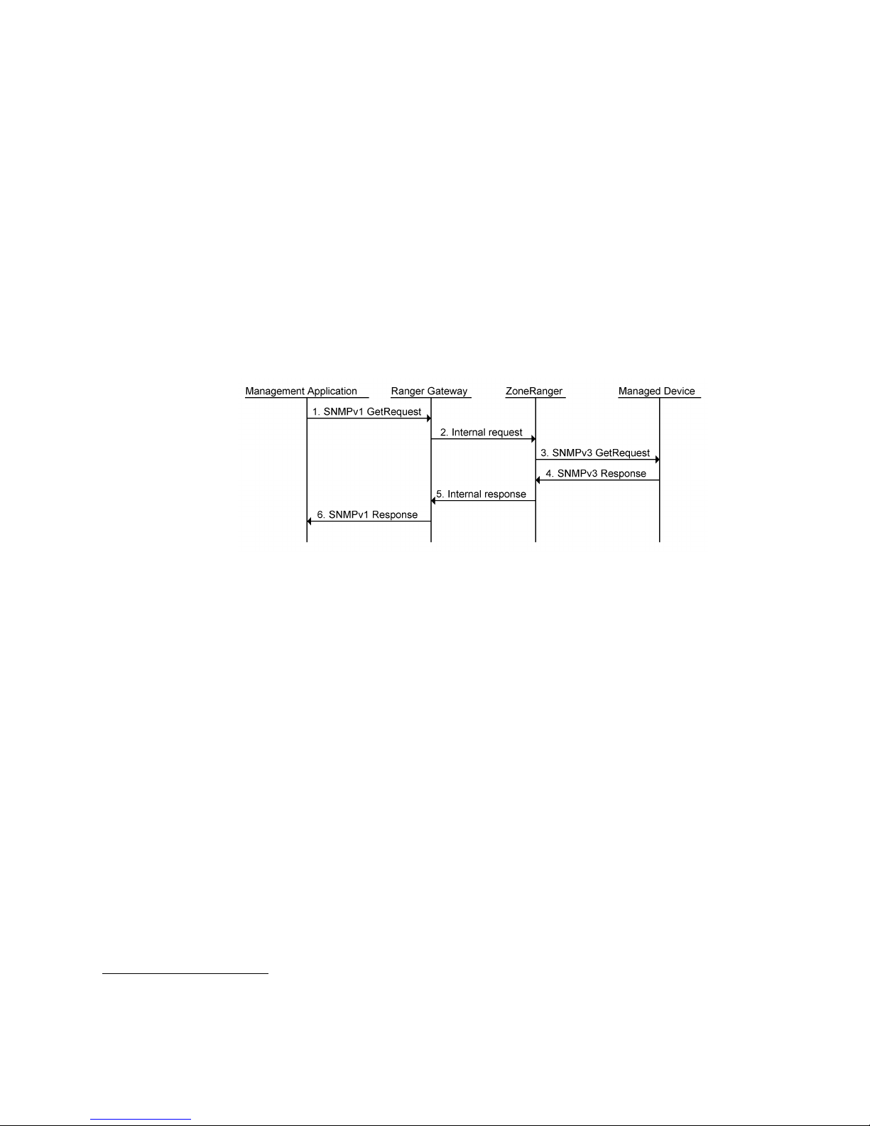
Community string conventions are best suited for management applications that can be configured
to send SNMP requests for all managed devices to a single address10. The primary advantage of
community string conventions is that there is no need to install a GVI driver, an RGVI client, or a
SOCKS shim on the management application server. The three-part community string format (e.g.
community@ZoneRanger@device) is also useful when managing networks with overlapping
addresses. The primary disadvantage is that the management application must be configured in an
atypical way in order to use the proxy. Some management applications require unique addresses for
each managed device, and do not support the concept of a common proxy address. In these cases, an
alternative SNMP proxy mechanism will need to be selected.
SNMPv3 Conversion
The ZoneRanger SNMP Proxy service can be used to proxy SNMPv1 and SNMPv2c requests to
managed devices. In addition, ZoneRanger can be configured to translate SNMPv1 or SNMPv2c
requests to SNMPv3 requests, as illustrated in the following figure.
This feature enables authentication and encryption of SNMP messages in firewall-partitioned
networks, such as a DMZ, where enhanced security is arguably most needed, while avoiding the
need to configure or upgrade existing management applications to support SNMPv3. SNMPv3
conversion can be configured on a per-device basis, so that the additional administrative effort
required for SNMPv3 can be limited only to those devices where security is most needed.
It is recommended that SNMPv3 users change the authentication and encryption passwords
associated with management devices on a regular basis. To facilitate this, the ZoneRanger web
interface includes a tool for automatically updating SNMPv3 passwords on managed devices. This
tool is located on the Administration > SNMP page SNMPv3 Passwords tab of the ZoneRanger
web interface.
10
Community string conventions can also be used when the management application uses different
addresses for different target devices. However, the GVI/RGVI, SOCKS, or IP address aliasing
mechanisms are likely to be preferred in such cases, because the need to configure special community
strings for each device is eliminated.
ZoneRanger 5.5 User's Guide
90
Page 91
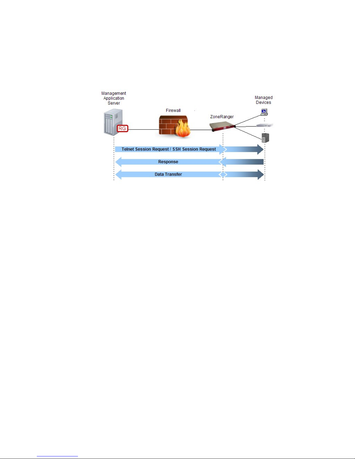
Chapter 28: TCP Proxy
A Ranger Gateway and one or more joined ZoneRangers can provide a TCP proxy service, enabling
management applications to establish TCP connections to devices located in firewall-partitioned
networks, without requiring the firewall to be configured to allow TCP connections.
The following figure provides a high-level overview of a TCP proxy transaction.
Figure 28-1. ZoneRanger TCP Proxy
The TCP proxy service is intended for use only in cases where the application protocol being carried
over the TCP connection is not supported by one of the more specific TCP-based proxy services (e.g.
Telnet, SSH, HTTP, HTTPS). Given that the application protocol being used is not identified, the TCP
proxy service is unable to perform any application layer protocol screening or filtering. As such, TCP
proxy is disabled by default, and should only be enabled for those devices/ports where it is absolutely
needed.
Management applications can access the TCP Proxy service in a variety of ways, as described in the
following sections.
GVI/RGVI
When using GVI or RGVI, the management application sends TCP connection requests intended for
a managed device to the actual address of the target device, or an address that can be uniquely
mapped to the target device. The management application server is configured with static routing
rules, so that traffic destined for devices located in firewall-partitioned networks is routed to a
virtual interface, which then forwards the traffic to the Ranger Gateway.
When the Ranger Gateway receives the TCP connection request, it will check the Proxy Access
Control configuration to verify that the request should be allowed, then will consult the Proxy Map
service in order to identify a ZoneRanger that is able to relay the request to the target device. The
request is forwarded to the selected ZoneRanger, which in turn, establishes a TCP connection to the
target device. Once this TCP connection is established, the ZoneRanger will inform the Ranger
Gateway, and the Ranger Gateway will complete the establishment of the initial TCP connection
(i.e. the connection between the management application and the Ranger Gateway). From this point
on, the Ranger Gateway and selected ZoneRanger will relay data between the management
application’s TCP connection to the Ranger Gateway and the ZoneRanger’s TCP connection to the
target device, until one of the connections is disconnected.
ZoneRanger 5.5 User's Guide
91
Page 92

The primary advantage of GVI and RGVI is that the existence of the TCP proxy is completely
transparent to the management application. Common routing mechanisms within the underlying
operating system are used to intercept traffic bound for devices in firewall-partitioned networks, so
there is no need to modify or reconfigure the management application in any way. Another
advantage is that the same mechanism can be used for other proxy services, such as ICMP proxy, or
SNMP proxy.
SOCKS
SOCKS is a standard protocol for generic TCP and UDP proxy services that can be used to redirect
management traffic from the management application to a SOCKS server integrated within the
Ranger Gateway. In order to use SOCKS, either the management application must include built-in
support for SOCKS, or generic SOCKS “shim” software must be installed on the management
application server. The shim software inserts itself between the management application and the
server’s TCP/IP stack, and redirects traffic for specified IP addresses and ports to a SOCKS server,
based on configuration information.
In order to access a managed device through TCP proxy, a SOCKS-aware web browser initially
establishes a TCP connection to the SOCKS port (by default, 4855) on the Ranger Gateway. After
this connection is established, the client application sends a SOCKS connection request to the
Ranger Gateway, indicating the managed device and port to which the client would like to connect.
The SOCKS server on the Ranger Gateway checks the Proxy Access Control configuration to verify
that the request should be allowed, then consults the Proxy Map service to identify a ZoneRanger
that is able to proxy traffic to the target device, and to translate the target address, if necessary. The
request is then forwarded to the selected ZoneRanger, which attempts to connect to the target
device. If this connection is successfully established, the ZoneRanger notifies the Ranger Gateway,
which in turn notifies the management application.
From this point, the Ranger Gateway and selected ZoneRanger simply relay data between the client
application’s TCP connection to the Ranger Gateway and the ZoneRanger’s TCP connection to the
target device. The Ranger Gateway and ZoneRanger continue to relay data until one of the
connections is disconnected.
Most web browsers support the SOCKS protocol. If a SOCKS-enabled web browser is not
available, you can use SOCKS “shim” software, which effectively inserts itself between the client
application and the networking layer on the host where the client application is running, and
redirects connection requests to a configured SOCKS server.
ZoneRanger 5.5 User's Guide
92
Page 93
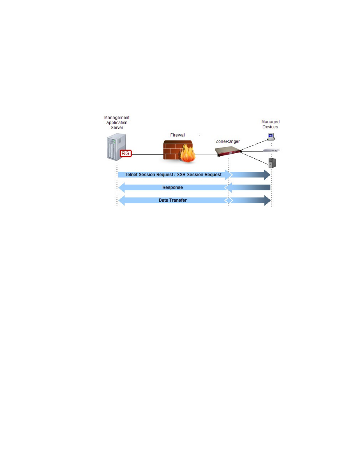
Chapter 29: Telnet/SSH Proxy
A Ranger Gateway and one or more joined ZoneRangers can provide an Telnet and SSH proxy service,
enabling Telnet and/or SSH client applications to have command line access to devices located in
firewall-partitioned networks, without requiring the firewall to be configured to pass Telnet or SSH
traffic.
The following figure provides a high-level overview of a Telnet/SSH proxy transaction. Note that the
Management Application Server in this figure is acting as a Telnet/SSH client, and one or more managed
devices may act as Telnet/SSH servers.
Figure 29-1. ZoneRanger Telnet/SSH Proxy
Telnet/SSH clients can range from simple command-line tools, to configuration management or security
management applications that use Telnet or SSH to communicate with managed devices. In addition to
using Telnet/SSH proxy to communicate with managed devices, the Telnet and SSH proxy services can
also be used to access the ZoneRanger text interface for joined ZoneRangers.
While the ZoneRanger is able to proxy both Telnet and SSH protocols, SSH will typically be the
preferred protocol for most applications, because the Telnet protocol, which exchanges user ID and
password information over an unencrypted TCP connection, is less secure. As a result, SSH proxy is
enabled by default and Telnet is disabled by default for managed devices.
Management applications can access Telnet and SSH Proxy services in a variety of ways, as described in
the following sections.
GVI/RGVI
When using GVI or RGVI, the management application sends Telnet or SSH requests intended for a
managed device to the actual address of the target device, or an address that can be uniquely
mapped to the target device. The management application server is configured with static routing
rules, so that traffic destined for devices located in firewall-partitioned networks is routed to a
virtual interface, which then forwards the traffic to the Ranger Gateway.
ZoneRanger 5.5 User's Guide
93
Page 94
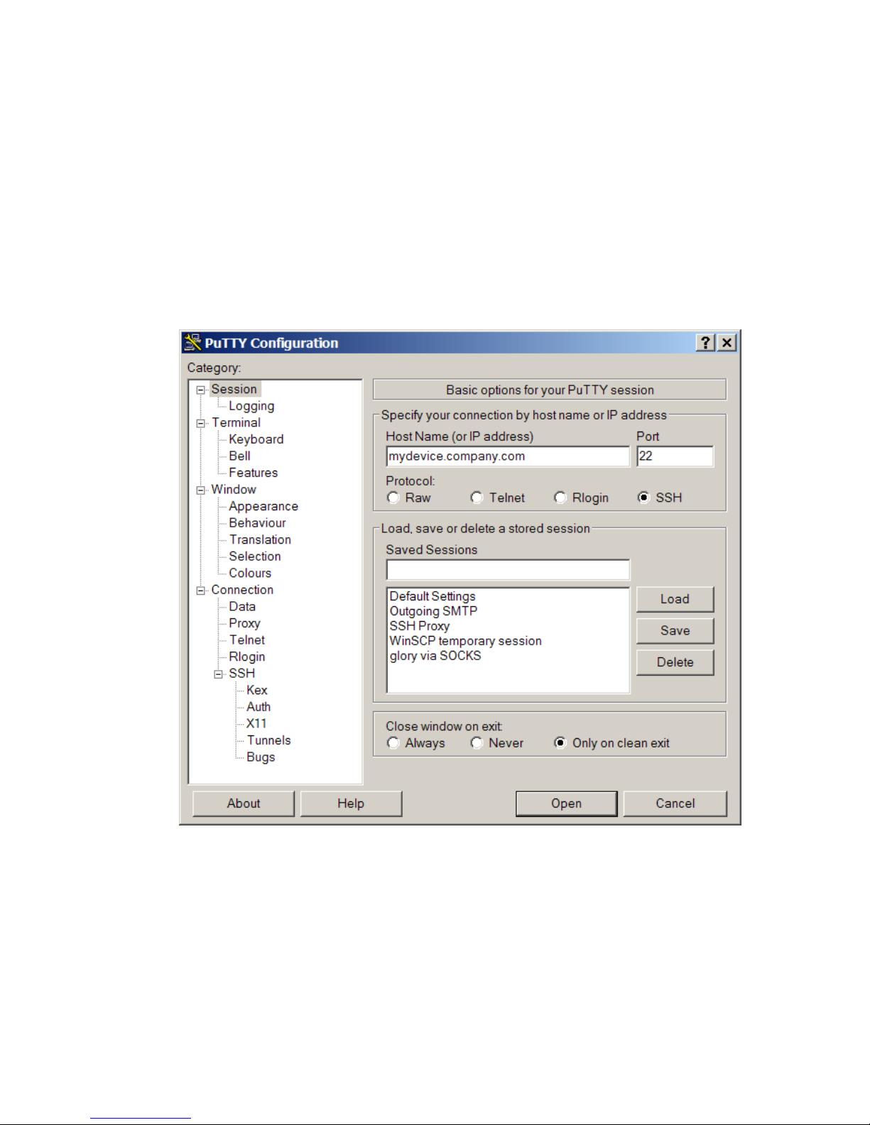
When the Ranger Gateway receives the initial TCP connection request for a Telnet or SSH
connection, it will check the Proxy Access Control configuration to verify that the request should be
allowed, then will consult the Proxy Map service in order to identify a ZoneRanger that is able to
relay the request to the target device. The request is then forwarded to the selected ZoneRanger,
which in turn, establishes a TCP connection to the target device. Once this TCP connection is
established, the ZoneRanger will inform the Ranger Gateway, and the Ranger Gateway will
complete the establishment of the initial TCP connection (i.e. the connection between the
management application and the Ranger Gateway). From this point on, the Ranger Gateway and
selected ZoneRanger will relay Telnet or SSH data between the management application’s TCP
connection to the Ranger Gateway and the ZoneRanger’s TCP connection to the target device, until
one of the connections is disconnected.
The following figure illustrates how PuTTY, a freely available Telnet/SSH client application, can be
used to establish an SSH session with a managed device via GVI or RGVI.
Figure 29-2. Ranger Gateway with PUTTY with GVI or RGVI
The steps to establish a connection, in this case are:
1. Enter the IP address or hostname of the target device.
2. Select the protocol to be used (SSH in this example).
3. Verify the port value. PuTTY will automatically set this value based on the selected
protocol. You may need to modify this value if the target device uses a non-standard port
for SSH or Telnet.
4. Click the Open button to establish the SSH session.
ZoneRanger 5.5 User's Guide
94
Page 95

The primary advantage of GVI and RGVI is that the existence of the Telnet/SSH proxy is
completely transparent to the management application. Common routing mechanisms within the
underlying operating system are used to intercept traffic bound for devices in firewall-partitioned
networks, so there is no need to modify or reconfigure the management application in any way.
Another advantage is that the same mechanism can be used for other proxy services, such as ICMP
proxy, or SNMP proxy.
SOCKS
SOCKS is a standard protocol for generic TCP and UDP proxy services that can be used to redirect
management traffic from the management application to a SOCKS server integrated within the
Ranger Gateway. In order to use SOCKS, either the management application must include built-in
support for SOCKS, or generic SOCKS “shim” software must be installed on the management
application server. The shim software inserts itself between the management application and the
server’s TCP/IP stack, and redirects traffic for specified IP addresses and ports to a SOCKS server,
based on configuration information.
In order to access a managed device through Telnet or SSH proxy, a SOCKS-aware Telnet/SSH
client application can initially establishes a TCP connection to the SOCKS port (by default, 4855)
on the Ranger Gateway. After this connection is established, the client application sends a SOCKS
connection request to the Ranger Gateway, indicating the DMZ device and port to which the client
would like to connect.
The SOCKS server on the Ranger Gateway will check the Proxy Access Control configuration to
verify that the request should be allowed, then will consult the Proxy Map service to identify a
ZoneRanger that is able to proxy traffic to the target device, and to translate the target address, if
necessary. The request is then forwarded to the selected ZoneRanger, which attempts to connect to
the target device. If this connection is successfully established, the ZoneRanger notifies the Ranger
Gateway, which in turn notifies the Telnet/SSH client.
From this point, the Ranger Gateway and selected ZoneRanger simply relay data between the client
application’s TCP connection to the Ranger Gateway and the ZoneRanger’s TCP connection to the
target device, allowing the SSH client and target device to establish a Telnet or SSH session. The
Ranger Gateway and ZoneRanger continue to relay data until one of the connections is
disconnected.
Most commercial Telnet/SSH client applications support the SOCKS protocol. If a SOCKS-enabled
SSH client is not available, you can use SOCKS “shim” software, which effectively inserts itself
between the client application and the networking layer on the host where the client application is
running, and redirects connection requests to a configured SOCKS server.
The following figures how PuTTY can be used to establish an SSH session with a managed device
through the SOCKS server in the Ranger Gateway.
ZoneRanger 5.5 User's Guide
95
Page 96
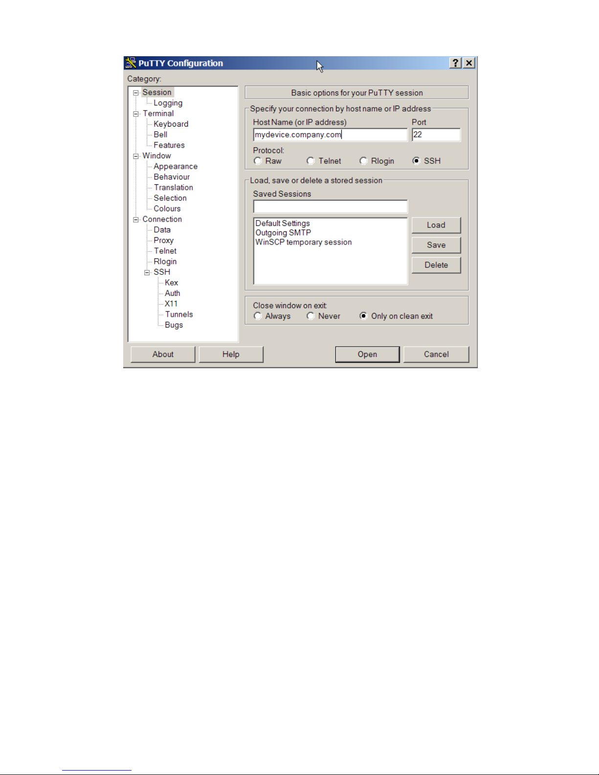
Figure 29-3. Ranger Gateway with PUTTY with SOCKS
The steps to establish a connection, in this case are:
1. Enter the IP address or hostname of the target device.
2. Select the protocol to be used (SSH in this example).
3. Verify the port value. PuTTY will automatically set this value based on the selected
protocol. You may need to modify this value if the target device uses a non-standard port
for SSH or Telnet.
4. Click Proxy in the Category pane on the left hand side of the window. The following page
is displayed.
ZoneRanger 5.5 User's Guide
96
Page 97
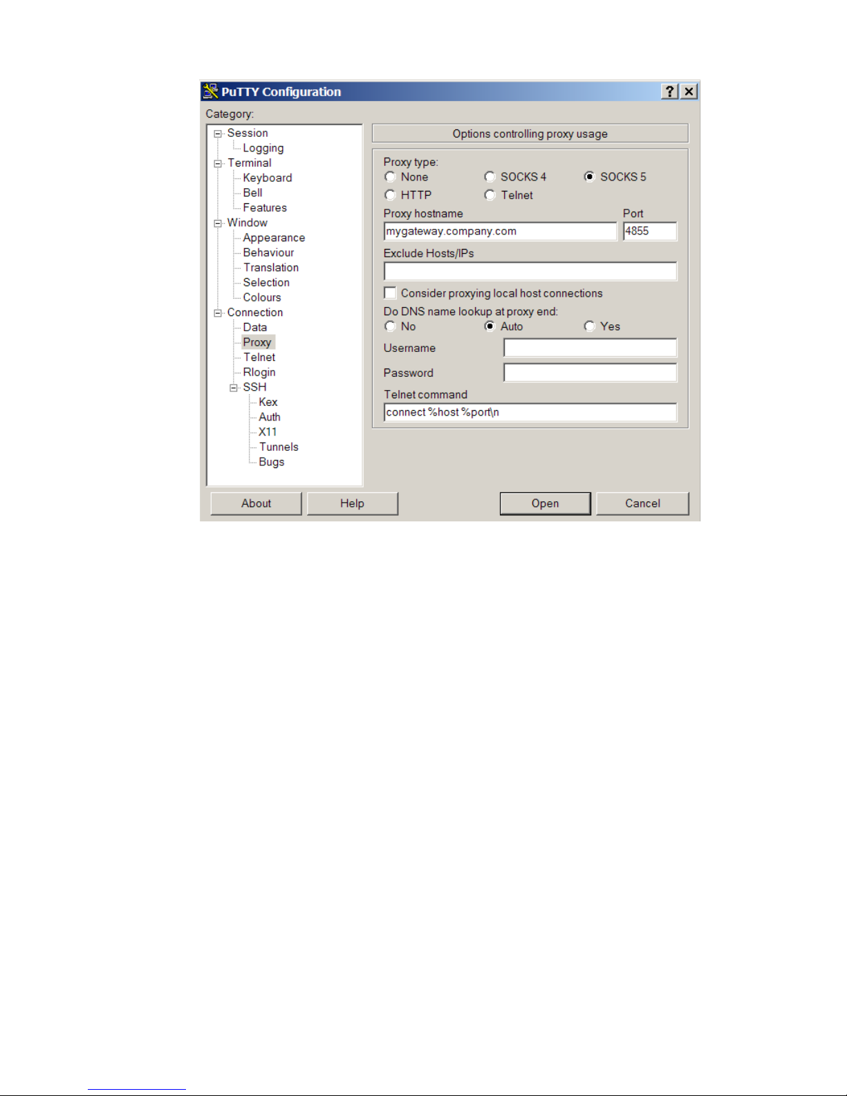
Figure 29-4. Ranger Gateway with PUTTY with SOCKS 5
5. Specify the Proxy type (SOCKS 5, for this example), Proxy hostname, which should be
the host name or IP address of the Ranger Gateway (for example,
mygateway.company.com), and the Port, which should be the SOCKS server port on the
Ranger Gateway (for example, 4855).
6. Depending on your DNS configuration, you may need to change the Do DNS name
lookup at proxy end setting. The Username and Password fields should be left blank.
7. Click the Open button to establish the SSH session.
One advantage of SOCKS over GVI/RGVI is that it is typically possible to configure the SOCKS
client to route traffic for certain ports to the Ranger Gateway, while traffic destined for other ports is
routed normally. In addition, some SOCKS clients can be configured to only intercept traffic sent
from specified applications. A disadvantage of SOCKS is that many management applications do
not provide built-in support for SOCKS and reliable SOCKS shims may not be available for the
operating system being used. In these cases, an alternative Telnet/SSH proxy access mechanism will
need to be selected.
ZoneRanger 5.5 User's Guide
97
Page 98

IP Address Aliasing
Most operating systems provide a means to associate multiple IP addresses with each network
interface (i.e. a primary address, and one or more “aliases”). If IP address aliases, corresponding to
managed devices located in firewall-partitioned networks, are defined on the management
application server, all traffic generated by the management application and destined for these
devices will be routed as local traffic to the interface where the IP address aliases have been defined.
If an SSH proxy port has been configured, the SSH Proxy service on the Ranger Gateway will listen
on that port for requests destined for any of these IP addresses. As a result, when a management
application sends a SSH request intended for a managed device to one of the configured alias
addresses, with the destination port set to the configured SSH proxy port, the Ranger Gateway will
receive the request.
If the management application and the Ranger Gateway software have been installed on the same
server, the IP address aliases can usually be added to the server’s loopback interface. In such cases,
it may be possible to configure the IP address aliases for managed devices to be the same as the
actual IP addresses of those devices. If the management application and the Ranger Gateway
software have been installed on different servers, the IP address aliases must be added to an
appropriate network interface on the Ranger Gateway server, and static routes will need to be
defined on the management application server to ensure that traffic related to SSH session requests
is routed to the Ranger Gateway server.
The SSH proxy port can be configured using the configGateway command or the Ranger
Gateway Viewer > Gateway Settings window. Note that by default, this feature is disabled and
the SSH proxy port is undefined. In addition, an SSH proxy destination port must be defined to
indicate the port on managed devices that the ZoneRanger should use to establish SSH proxy
sessions. The SSH proxy destination port can be defined using the configGateway command or the
Ranger Gateway Viewer > Gateway Settings window. The default value is 22. Note that the IP
address aliasing mechanism does not support Telnet proxy.
To access a managed device using SSH proxy, an SSH client application would establish a TCP
connection to the IP address on the Ranger Gateway that is associated with the target device,
specifying the configured SSH proxy port as the destination port. After this connection is
established, the Ranger Gateway will check the Proxy Access Control configuration to verify that
the request should be allowed, then will consult the Proxy Map service to identify the target device,
and to select a ZoneRanger that is able to proxy traffic to the target device. The connection request
is then forwarded to the selected ZoneRanger, which attempts to connect to the target device.
If this connection is successfully established, the ZoneRanger notifies the Ranger Gateway. From
this point, the Ranger Gateway and selected ZoneRanger simply relay data between the client
application’s TCP connection to the Ranger Gateway and the ZoneRanger’s TCP connection to the
target device, enabling the SSH client and target device to establish an SSH session. The Ranger
Gateway and ZoneRanger continue to relay data until one of the connections is disconnected.
ZoneRanger 5.5 User's Guide
98
Page 99

The following figure illustrates how to use PuTTY to establish an SSH session with a managed
device, using the SSH proxy port on the Ranger Gateway.
Figure 29-5. Ranger Gateway with PUTTY with IP Address Aliasing
The steps to establish a connection, in this case are:
1. Enter the IP address or hostname of the target device (64.10.37.5, in this case).
2. Select the protocol to be used (SSH in this example).
3. Enter the configured SSH proxy port value (4822 in this example) in the Port field.
4. Click the Open button to establish the SSH session.
The IP address aliasing approach for SSH proxy has the following advantages:
• It can be used in cases where the Ranger Gateway software is installed on a server with an
operating system that does not support GVI.
• It does not require a SOCKS-enabled SSH client or SOCKS shim.
The main disadvantage of the IP address aliasing technique is the administrative effort required to
add and maintain IP address aliases for all managed devices on the Ranger Gateway server. Another
concern is that operating systems may limit the number of IP address aliases that can be defined. As
a result, this technique may not be able to support the required number of managed devices for some
applications.
ZoneRanger 5.5 User's Guide
99
Page 100
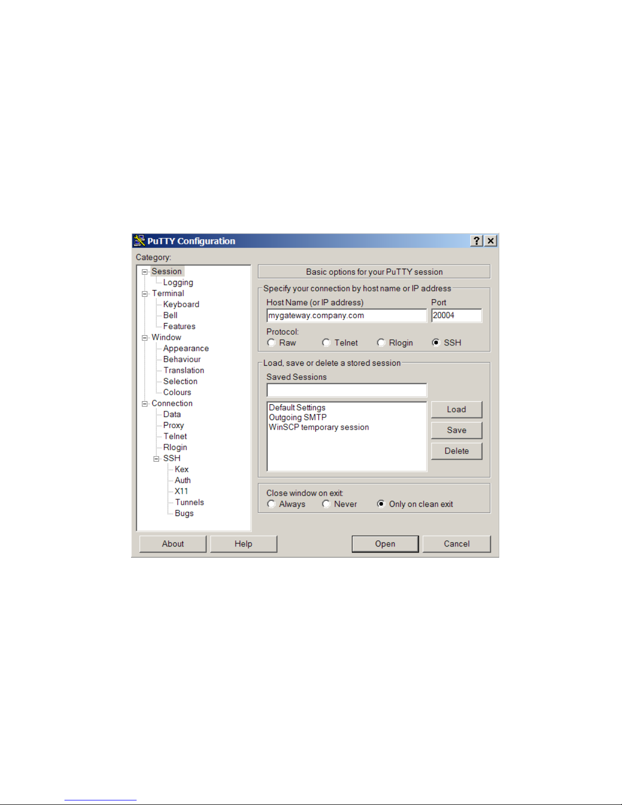
Dedicated Telnet/SSH Ports
When a ZoneRanger is joined to a Ranger Gateway, the Ranger Gateway allocates dedicated ports
that can be used to access various services,HTTP, HTTPS, SQL, Telnet, and SSH, on the newly
joined ZoneRanger. You can use the listTcpPorts command on the Ranger Gateway command
interface or the Ranger Gateway Viewer to identify the ports that have been allocated for each
ZoneRanger.
A Telnet/SSH client application can establish a proxy connection to a joined ZoneRanger simply by
connecting to the ranger Gateway’s address, specifying the dedicated Telnet or SSH port associated
with that ZoneRanger as the destination port.
The following figure illustrates how to use PuTTY to establish an SSH session with a joined
ZoneRanger, using that ZoneRanger’s dedicated SSH proxy port on the Ranger Gateway.
Figure 29-6. Ranger Gateway with PUTTY with dedicated ports
The steps to establish a connection, in this case are:
3. Enter the IP address or hostname of the target device (mygateway.company.com, in this
example).
4. Select the protocol to be used (SSH in this example).
5. Enter the configured SSH proxy port value (20004 in this example) in the Port field.
6. Click the Open button to establish the SSH session.
ZoneRanger 5.5 User's Guide
100
 Loading...