

Page 1
XE330-C09
Page 2

1
SAFETY HINTS
WARNING - Read all instructions before using this appliance.
■ Do not operate elliptical on deeply padded, plush or shag carpet. Damage to both
carpet and elliptical may result.
■ Keep children away from the elliptical. There are obvious pinch points and other
caution areas that can cause harm.
■ Keep hands away from all moving parts.
■ Never operate the elliptical if it has a damaged cord or plug. If the elliptical is not working
properly, call your dealer.
■ Keep the cord away from heated surfaces.
■ Do not operate where aerosol spray products are being used or where oxygen is
being administered. Sparks from the motor may ignite a highly gaseous environment.
■ Never drop or insert any object into any openings.
■ Do not use outdoors.
■ To disconnect, turn all controls to the off position, then remove the plug from the outlet.
■ Do not attempt to use your elliptical for any purpose other than for the purpose it is
intended.
■ The pulse sensors are not medical devices. Various factors, including the user’s
movement, may affect the accuracy of heart rate readings. The pulse sensors are
intended only as exercise aids in determining heart rate trends in general.
■ Wear proper shoes. High heels, dress shoes, sandals or bare feet are not suitable
for use on your elliptical. Quality athletic shoes are recommended to avoid leg fatigue.
SAVE THESE INSTRUCTIONS - THINK SAFETY!
CAUTION!! Please be careful when opening this unit.
XE330-C08&C09_1012C
Page 3
2
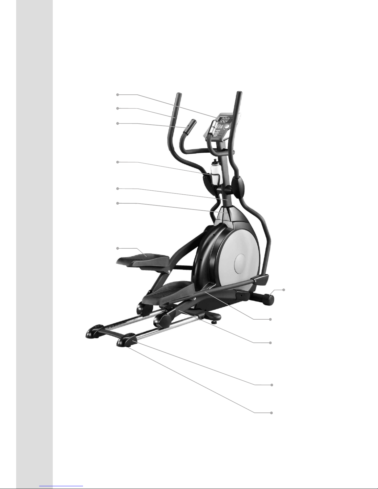
INTRODUCTION
Console
Handle Bar
Console Mast Cover
Wheel
Connecting Arm
Pedal Arm
Rear Stabilizer Cover
Cushion (Foot Pad)
Pedal
Handpulse
Console Mast
Drink Bottle Holder
Page 4

3
ASSEMBLY
PACK
CHECK
LIST
ASSEMBLY PACK CHECK LIST
Step 1
#70. 5/16" x 15m/m
Hex Head Screw (6pcs)
#97. 5/16"x 23 x1.5T
Flat Washer (4pcs)
#102. 5/16"x 23 x2T
Curved Washer (2pcs)
Step 2
#97. 5/16" x 23 x 1.5T
Flat Washer (2pcs)
#70. 5/16" x 15m/m
Hex Head Screw (2pcs)
#101. ψ17
Wavy Washer (2pcs)
#75. 5/16" x 15m/m
Button Head Socket Screw (6pcs)
#71. 5/16 x 32m/m
Hex Head Screw (2 pcs)
#98. 5/16" x 20 x 1.5T Flat
Washer (4 pcs)
#105. 5/16" x 7T
Nylon Nut (2 pcs)
#89. 3/8" x 7T
Nylon Nut (2 pcs)
#94. 3/8" x 19 x 1.5T Flat
Washer (2 pcs)
Step 3
#76. 5/16 x 3/4"
Button Head Socket Screw (2 pcs)
#77. 3/8 x 2-1/4"
Button Head Socket Screw (2 pcs)
#78. M5 x 10m/m
Phillips Head Screw (4pcs)
* these four screws are attached in
the back of the console.
Page 5
4
ASSEMBLY
PACK
CHECK
LIST
#84. ψ3.5x12m/m
Self Tapping Screw (8pcs)
#79. M5 x 15m/m
Phillips Head Screw (8pcs)
ASSEMBLY PACK CHECK LIST
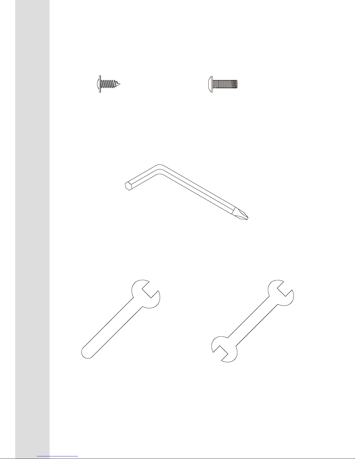
Step4
Tools
#108. Combination M5 Allen Wrench
& Phillips Head Screw Driver (1 pc)
#110. 12m/m Wrench ( 1pc)
#111. 13/14m/m Wrench ( 2pcs)
Page 6

5
ASSEMBLY
DRAWING
Step 1
Page 7
6
ASSEMBLY
DRAWING
Step 2
Page 8

7
ASSEMBLY
DRAWING
Step 3
Page 9

8
ASSEMBLY
DRAWING
Step 1
Page 10

9
ASSEMBLY
Assembly
■ UNPACKING THE UNIT
1. Using a razor knife (Box Cutter) cut the outside, bottom, edge of box along the dotted Line. Lift Box
over the unit and unpack.
2. Carefully remove all parts from carton and inspect for any damage or missing parts. If damaged
parts are found, or parts are missing, contact your dealer immediately.
3. Locate the hardware package. The hardware is separated into steps. Remove the tools first. Remove
the hardware for each step as needed to avoid confusion.
STEP 1: CONSOLE MAST ASSEMBLY
1. Locate the Console Mast (10) and Console Mast Cover (41) and slide the Cover onto the
Mast as far as it will go. Make sure the Console Mast Cover (41) is facing the correct way.
2. At the top opening of the Main Frame (1) of the elliptical is a Computer Cable (32).
Unravel and straighten out the Computer Cable (32) and feed it into the bottom of the
console mast tube (10) and out of the top opening.
3. Install the Console Mast (10) into the receiving bracket in the top of the Main Frame (1).
Put the 4pcs of 5/16"x 23 x1.5T Flat Washers (97) onto the 4pcs of 5/16" x 15m/m Hex
Head Screws (70) and the 2pcs of 5/16” x 23 x 2T Curved Washers (102) onto the 2pcs of
5/16" x 15m/m Hex Head Screws (70). Install, and hand tighten by using the 12m/m
Wrench (110).
NOTE: There is a electrical wire running through the Console Mast Tube (10). Be careful
not to damage or pinch this Computer Cable (32) during this procedure.
4. Locate the Console (31) and the 4 pcs of M5 x 10m/m Phillips Head Screws (78) by using
the Combination M5 Allen Wrench & Phillips Head Screw Driver (108).
5. There will be three electrical wire connectors at the top opening of the Console Mast (10),
two 2 pin Hand pulse Cable (37-3), one Computer Cable (32). Connect these to the mating
connectors on the back of the Console (31). The connectors are keyed so you cannot plug
them in the wrong way so do not force them.
6. Storing the excess wire back into the Console Mast (10), carefully install the Console (31)
onto the mounting plate of Console Mast (10) and secure using the 4 pcs of M5 x 10m/m
Phillips Head Screws (78).
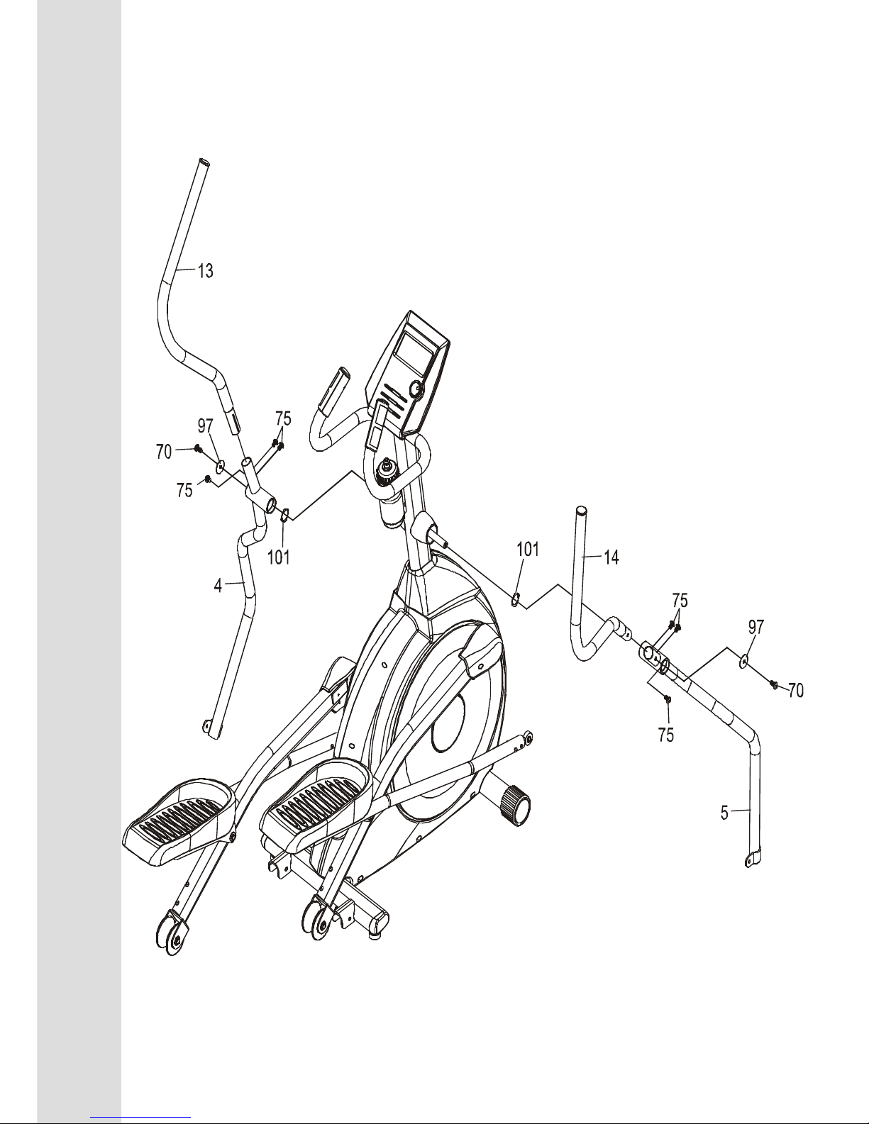
STEP 2: HANDLE BAR ASSEMBLY
1. Install the 2 pcs of ψ17 Wave Washers (101) onto the Left and Right side of the Handle Bar
axle.
2. Slide the Lower Left and Right Handle Bars (4&5) onto the appropriate side of the axle.
3. Put the 2 pcs of 5/16" x 23 x 1.5T Flat Washers (97) onto the 2 pcs of 5/16" x 15m/m Hex
Head Screws (70) and install, and tighten, in the threaded holes in the ends of the axle.
4. Install the Left and Right Handle Bars (13&14) into the Lower Left and Right Handle Bars
(4&5) with 6pcs of 5/16 x15m/m Button Head Socket Screws (75) by using the
Combination M5 Allen Wrench & Phillips Head Screw Driver (108).
Page 11

10
ASSEMBLY
STEP 3: CONNECTING ARM ASSEMBLY
1. Align the hole in the end of the Connecting arms (L&R)(7&8)(pivoting rod end) with the
hole in the bracket of the Lower Handle Bars (L&R)(3&4). The rod end should be on the
inside of the Lower Handle Bars (L&R)(3&4). bracket. Take 2pcs of 5/16" x 1-1/4" Hex
Head Screws (71) and install it through the Lower Handle Bars (L&R)(3&4) bracket and
the rod end. Install 2pcs of 5/16" x 20 x 1.5T Flat Washers (98), 2pcs of 5/16" x 7T
Nylon Nuts(105) tighten firmly using the 12m/m Wrench (111) on the 5/16" x 7T Nylon
Nut (105)and one on the 5/16" x 1-1/4" Hex Head Screw(71).
2. Install the 2 pcs of Rails (15) into the receiving bracket in the end of Main Frame(1) with 2
pcs of 3/8” x 2-1/4” Button Head Socket Screws(77) , 2pcs of 3/8" x 19 x 1.5T Flat
Washers(94) and 2 pcs of 3/8" x 7T Nylon Nut (89) by using 2 pcs of 13/14m/m Wrench
(111).
3. Put the Lug Cover (L) (61) and Lug Cover (R)(62) onto the Iron Plate (16).
Install the Rails (15) with 2 pcs of 5/16” x 3/4” Button Head Socket Screws (76) and 2 pcs
of 5/16" x 20 x 1.5T Flat Washers (98) by using Combination M5 Allen Wrench &
Phillips Head Screw Driver (108).
STEP 4: PLASTICS ASSEMBLY
1. Install the Connecting Arm Covers (L & R) (59 & 60) over the connection of the rod end
and Lower Handle Bars (L & R) (4 & 5) with 4pcs of M5 x 15m/m Phillips Head
Screws(79) and 2pcs of ψ3.5x12m/m Self Tapping Screws(84) by using the Combination
M5 Allen Wrench & Phillips Head Screw Driver (108).
2. Install the 2pcs of Wheel Covers(52) using the 4pcs of M5x15m/m Phillips Head
Screws(79).
3. Install the Front Handle Bar Cover (L & R) (54 & 56) and Rear Handle Bar Cover (L &
R) (55 & 57) over the Handle Bars axle connections with the 6 pcs ofψ3.5x12m/m Self
Tapping Screws (84) by using Phillips Head Screw Driver (108).
PLEASE ENSURE ALL FASTENERS ARE TIGHT AFTER THE COMPONENTS
HAVE BEEN ASSEMBLED.
Page 12

11
LUBRICATION &
TRANSPORT
■■■■TRANSPORT
The
elliptical
is equipped with two transport wheels which are engaged when rear of it is lifted.
■■■■LUBRICATION
1. Pour 2c.c of the lubricant under the middle of Rail. You must be pour lubricant each three
months.
2. If the user felt the exercise is not smooth or there were some noise during exercising, please pour
2 c.c.of the lubricant on the middle of Rails.
Page 13

12
FUNCTIONS
Starting a program
Quick Start
After the console power on you must to set date and time by rotating Enter key, then press Enter key to
confirm. After finishing the installation time you may press the Start key to begin, this will initiate the
Quick Start mode. In Quick Start the Time will count up from zero and the workload may be adjusted
manually by rotating the Enter button. Distance and Calories will accrue, starting from zero.
The bottom right data window will switch between RPM and Speed every 5 seconds. RPM is your actual
pedal rotation speed, and the Speed readout is in MPH, indicating approximate road speed as if pedaling a
bicycle in 7
th
gear.
The Distance window shows distance traveled, based on pedal speed, in miles. The Pulse window will
display your heart rate in beats per minute if you are holding the heart rate hand sensors, or wearing a chest
strap transmitter.
The Calorie reading shows total Calories burned and is an approximate number. The Watt reading indicates
how much work you are doing. If the Watt reading is 100, this means you are doing enough work to light a
100 watts light bulb.
COMPUTER
OPERATION INSTRUCTIONS
Page 14

13
FUNCTIONS
Manual
After power up, or reset, highlight the Manual icon at the bottom of the display and press Enter key.
The profile will be blinking and you may rotate the Enter key to adjust the program workload and then
press Enter. The Time window will now be blinking. Rotate the Enter key to adjust the program Time and
then press Enter. The Distance window will now be blinking and you can adjust a target Distance using the
Enter key then press Enter. The Calories window will now be blinking and you can adjust a target Calories
using the Enter key then press Enter. Pulse will now be blinking, repeat the same process as above to set,
then press Enter. After adjusting all the parameters, press Start to begin your workout.
Preset Programs
There are 12 preset programs to choose from. After power up, or reset, rotate the Enter key to highlight the
Program icon. Press the Enter key to enter the program mode. The display will show P1, for two seconds,
then change to the P1 program profile. You may keep rotateing the Enter key to scroll through the 12
programs. When you see a program you want, press the Enter key to enter.
At this point you may press start to begin the program with the default settings or you may customize the
program.
To customize the workload, rotate the Enter key. You will see the profile increase in size. When the
workload is where you like it press the Enter key (If you do not want to customize the profile, just press the
Enter key to bypass).
The Time window will now be blinking. Use the Enter key to adjust the workout time and then press Enter.
The Distance window will now be blinking. Repeat the same process to set the distance to count down, if
desired, and press Enter.
The Calorie window will now be blinking. Repeat the same process then press Enter.
The Pulse window will now be blinking. Entering a Pulse number will set an alarm that will beep when
your heart rate reaches the programmed number to let you know you have reached your target.
Once you have set the data you may press Start to begin the program. You may also press Start at any time
during the programming to begin. Any data that is not programmed at that point will count up from zero.
When the program ends there is a series of audible beeps. You may press Start to restart the program or
press Reset to return to the start-up screen.
User Program
This mode allows you to build and save your own custom program.
Rotate the Enter key until the User icon at the bottom of the display is blinking then press Enter. The first
column of the profile will be blinking. Rotate the Enter key to adjust the work load then press Enter. The
second column will now be blinking. Repeat the same process as above and press Enter. Repeat this
process until all the columns are adjusted to your liking. All the settings will be saved as a custom program.
You may press the Start key to begin.
Target HR
This program allows you to set a target heart rate and the machine will automatically adjust the work load
to safely reach the target and maintain that target.
Use the Enter key to select the Target HR program and press Enter. The display will show a number and
the age icon at top will be blinking. Rotate the Enter key to adjust the age and press Enter. The display will
now show a blinking percent number or the letters THR.
You may use the Enter key to choose either 55%, 75%, 90% or THR. The percentage choices will
automatically set the target to a percent of your maximum heart rate, based on your age. This is why it is
important to adjust the age properly. The console will use a formula to determine the correct percentage:
220 – age = maximum HR. For example a 30 year old persons’ Max HR is 190 BPM (220 – 30 = 190
BPM). If the 30 year old wants to work at 75%, their target HR will be 142BPM.
Page 15

14
FUNCTIONS
If you want to choose to work at 75% - for example - then use the Enter arrow to highlight 75% and press
Enter. Now the Time window will be blinking and you can program it and other data the same as other
programs. If you want to set your own custom Target HR then rotate the Enter arrow to highlight THR
and press Enter. The Pulse window will now be blinking. Use the Enter arrows to set your own Target
HR and press Enter to continue.
NOTE: E
lliptical’s console have attach receiver, have to match transmitter to play target HR program. User can to
get accuate heart rate in exercise.
Watt
After power up, or reset, rotate the Enter key to highlight the Watt icon. Press the Enter key to enter the Watt
mode.
When you choose to set the Watts then the machine will automatically adjust the workload to
maintain continuous work. What this means is that if you set the Watt to 100 the machine will try to keep
you working at a rate of work that equals 100 Watts (or working at a rate that will keep a 100 Watt light
bulb burning). Watts are determined by the amount of work you are doing. On the Elliptical this means
the speed you are pedaling at combined with the workload of the machine.
In Watt mode, if you change your speed the machine will automatically change the workload to maintain the
same Watt load. If you pedal faster the workload will decrease and if you pedal slower the workload
increases.
After adjusting all the parameters, press Start to begin your workout.
FUNCTIONS
TIME: Count up: accumulates training time from zero to 99:59.
Count down: counts down from preset time to zero.
SPEED/ RPM: Automatically toggles between SPEED and RPM every 6 seconds.
Speed is in miles per hour (or kilometers per hour)
DISTANCE: Count up: accumulates training distance from 0.00 to 99.9 miles.
Count down: counts down from preset distance to zero.
CALORIES: Accumulates calories burned from 0 to 999. This is an estimated number only to be used
from workout to workout to compare your progress. Actual calorie burn cannot be
measured accurately on any consumer exercise equipment because every individual
burns calories at a different rate.
WATT: Indicates the amount of work being done in Watts.
PULSE: Displays your current heart rate when you grasp the hand sensors or wear the chest strap
transmitter.
LOAD: Shown next to the workout profile. Indicates the level of work being done from 1 to 8.
RECOVERY: Used to measure how fast your heart rate (HR) recovers from exercise. The faster your
HR returns to normal from exercise level, the better aerobic shape you are in. Pressing
the recovery button will start a 60 second count down. Hold the hand pulse sensors and
do not exercise during the count down. At the end of the 60 seconds a score will be
displayed ranging from F1 to F6 with F1 being the highest score and F6 being the
lowest.
TEMPERTURE: Displays current room temperature from 0℃ to 60℃.
Page 16

19
WARM
Quadriceps Stretch
With one hand against a wall for balance, reach behind you
and pull your right foot up. Bring your heel as close to your
buttocks as possible. Hold for 15 counts and repeat with
left foot up.
Inner Thigh Stretch
Sit with the soles of your feet together with your knees
pointing outward. Pull your feet as close into your groin as
possible. Gently push your knees towards the floor. Hold
for 10 counts
Toe Touches
Slowly bend forward from your waist, letting you back and
shoulders relax as you stretch toward your toes. Reach
down as far as you can and hold for 15 counts.
Hamstring Stretches
Sit with your right leg extended. Rest the sole of your left
foot against your right inner thigh. Stretch toward your toe
as far as possible. Hold for 15 counts Relax and then repeat
with left leg extended.
Page 17

18
AEROBIC EXERCISE
Aerobic exercise is any sustained activity that sends oxygen to your muscles via your heart and lungs.
Aerobic exercise improves the fitness of your lungs and heart - your body’s most important muscle.
Aerobic exercise fitness is promoted by any activity that uses your large muscle -arms, legs, or buttock,
for example. Your heart beats quickly and you breathe deeply. An aerobic exercise should
be part of your entire exercise routine.
WEIGHT TRAINING
Along with aerobic exercising which helps get rid of and keep off the excess fat that our bodies can
store, weight training is an essential part of the exercise routine process. Weight training helps tone,
build and strengthen muscle. If you are working above your target zone, you may want to do a less
amount of reps. And as always ,consult your physician before beginning any exercise program.
MUSCLE CHART
CYCLE
The exercise routine that is performed on the cycle will develop the lower body muscle group as well
as condition the circulatory system and provide a good aerobic workout . These muscle groups are
highlighted on the muscle chart below.
Page 18

20
OVERVIEW
CHART
Page 19

21
S
LIST
NO. DESCRIPTION O'TY
1 Main Frame 1
2 Pedal Arm (L) 1
3 Pedal Arm (R) 1
4 Lower Handle Bar (L) 1
5 Lower Handle Bar (R) 1
6 Bushing Housing, Pedal Arm 2
7 Connecting Arm (L) 1
8 Connecting Arm (R) 1
9 Cross Bar 2
10 Console Mast 1
11 Idler Wheel Assembly 1
12 Crank Axle 1
13 Swing Arm (L) 1
14 Swing Arm (R) 1
15 Rail Tube 2
16 Rail Strap 1
17 Blacking Arbor for Pedal 2
18 Axle for Slide Wheel 2
19 Rod End Sleeve 3
20 6005_Bearing 2
21 6203_Bearing 6
22 6003_Bearing 8
23 Rod End Bearing 2
24 Ø31 × Ø25.5 × Ø19 × 16+3T_Bushing 4
25 350m/m_Steel Cable 1
26 Drive Belt 1
27 Ø330_Drive Pulley 1
28 Flywheel 1
29 Magnet 1
30 25 × 7 × 7m/m_Woodruff Key 2
31 Console Assembly 1
32 1100m/m_Computer Cable 1
33 600m/m_DC Power Cable 1
34 Gear Motor 1
35 250m/m_Sensor W/Cable 1
36 Sensor Rack 1
37 850m/m_Handpulse W/Cable Assembly 2
37~4 Ø3 × 20m/m_Tapping Screw 4
38 Power Adaptor 1
39 Slide Wheel , Urethane 2
40~1 3/8" × 2"_Flat Head Socket Bolt 2
40~2 Rubber Foot 2
41 Console Mast Cover 1
42 Side Case(L) 1
43 Side Case(R) 1
Page 20

22
PARTS
LIST
NO. DESCRIPTION O'TY
11 Round Disk 2
15 Round Disk Cover 2
46 Cover Swing Arm Axle 2
47 Pedal Arm Cover (L) 1
48 Pedal Arm Cover (R) 1
50 Pedal (L) 1
51 Pedal (R) 1
52 Slide Wheel Cover 2
53 Button Head Plug 4
54 Front Handle Bar Cover (L) 1
55 Rear Handle Bar Cover (L) 1
56 Front Handle Bar Cover (R) 1
57 Rear Handle Bar Cover (R) 1
58 Round Cap 2
59 Connecting Arm Cover (L) 2
60 Connecting Arm Cover (R) 2
61 Lug Cover (L) 1
62 Lug Cover (R) 1
63 Transportation Wheel 2
64 Oval End Cap 2
65 EVA Foam for Rail Strap 1
66 Handgrip Foam 2
67 Rubber Foot 2
68~1
Drink Bottle(Optional)
1
68~2 Drink Bottle Holder 1
68~3 M5 × 12m/m_Phillips Head Screw 2
69 35 × 25.5 × 5T_Bushing 1
70 5/16" × 15m/m_Hex Head Bolt 20
71 5/16" × 32m/m_Hex Head Bolt 2
72 1/4" × 3/4"_Hex Head Bolt 4
73 3/8" × 2-1/4"_Socket Head Cap Bolt 2
74 M8 × 30L_Socket Head Cap Bolt 2
75 5/16" × 15m/m_Button Head Socket Bolt 6
76 5/16" × 3/4"_Button Head Socket Bolt 2
77 3/8" × 2-1/4"_Button Head Socket Bolt 2
78 M5 × 10m/m_Phillips Head Screw 2
79 M5 × 15m/m_Phillips Head Screw 8
80 5 × 16m/m_Tapping Screw 7
81 5 × 25m/m_Tapping Screw 2
82 4.8 × 38m/m_Sheet Metal Screw 1
83 5 × 16m/m_Tapping Screw 12
84 Ø3.5 × 12m/m_Sheet Metal Screw 8
86 Ø17_C Ring 1
87 M8 × 7T_Nyloc Nut 1
88 1/4"_Nyloc Nut 4
Page 21

23
PARTS
LIST
NO. DESCRIPTION O'TY
89 3/8" × 7T_Nyloc Nut 2
90 3/8" -UNF26 × 4T_Nut 2
91 3/8" -UNF26 × 9T_Nut 2
92 3/8" × 7T_Nut 4
93 M12_Nut 2
94 3/8" × 19 × 1.5T_Flat Washer 9
96 5/16" × 35 × 1.5T_Flat Washer 2
97 5/16" × 23 × 1.5T_Flat Washer 14
98 5/16" × 20 × 1.5T_Flat Washer 8
99 1/4" × 19m/m_Flat Washer 13
100 J Bolt 1
101 Ø17_Wave Washer 6
102 5/16" × 23 × 2T_Curved Washer 2
103 M8 × 20m/m_Carriage Bolt 1
104 Ø17 × Ø23.5 × 2T_Flat Washer 2
105 5/16" × 7T_Nyloc Nut 2
106 3.5 × 16m/m_Tapping Screw 3
108 Combination M5 Allen Wrench & Phillips Head Screw Driver 1
110
12m/m_Wrench
1
111
13.14m/m_Wrench
2
112 5 × 19m/m_Tapping Screw 2
133 M5 × 10m/m_Phillips Head Screw 8
135 M8 × 9T_Nyloc Nut 1
136 3/8" × 11T_Nyloc Nut 2
137 3.5 × 16m/m_Sheet Metal Screw 7
138 M8 × 6.3T_Nut 4
144 3/8" -UNF26 × 6T_Nut 1
145
Axle Stopper
1
146 M5 × 5m/m_Slotted Set Screws 2
 Loading...