

Page 1
Assembly and operating instructions
Elliptical cross trainer X7.7
Art. No. TF-X77
Page 2

X7.7
2
Page 3

3
Dear Customer,
Thank you for deciding for a high-quality training equipment of the brand Taurus,
the brand that makes athlete‘s hearts beat faster. Taurus oers a wide range of home
tness equipment like elliptical cross trainers, ergometers, tread-mills and rowing
machines. Taurus equipment is the optimal equipment for all those who want to train
at home independent of goals and tness level. For further information please visit
www.sport-tiedje.com or www.taurus-tness.de.
SAFETY NOTICE
Please read all of the instructions carefully before assembly and rst
use. These instructions are intended to ensure speedy assembly and
explain safe usage. Make sure that all people exercising with the
equipment (in particular children and persons with limited physical, sensory, mental or
mo-tor capabilities) are informed about these instructions and its content in advance.
In case of doubt, a responsible person must supervise the use of the equipment.
This equipment has been manufactured according to the latest safety knowledge. As
far as possible, potential safety hazards which could cause injury have been eliminated.
Make sure to follow the instructions carefully and that all parts are securely in place. If
required, read through the instructions again to correct any mistakes.
Please pay close attention to the safety and maintenance instructions given here. The
contract partner cannot be held liable for damage to health, accidents or damage to
the equipment when it is not used in accordance with these instructions.
The equipment is suitable for home use as well as semi-professional use (e. g.,
hospitals, clubs, hotels, schools, etc.). It is not suitable for commercial or professional
use (e. g., commercial gyms).
Retain these instructions in a safe place for future reference, maintenance or when
ordering replacement parts.
Page 4

X7.7
4
CONTENTS
1 GENERAL INFORMATION 6
1.1 Technical data 6
1.2 Personal safety 7
1.3 Electrical safety 8
1.4 Set-up place 8
2 ASSEMBLY INSTRUCTIONS, MAINTENANCE AND CARE 9
2.1 General instructions 9
2.2 Faults and troubleshooting 10
2.3 Maintenance and service calendar 11
3 ASSEMBLY 11
3.1 Package contents 11
3.2 Assembly instructions 16
4 OPERATING INSTRUCTIONS 28
4.1 Console display 28
4.2 Button functions 29
4.3 Turning on the equipment 29
4.4 Programmes 30
4.4.1 Manual programme 30
4.4.2 Training programmes 32
4.4.3 Heart rate controlled programmes 33
5 WORKOUT INSTRUCTIONS 36
5.1 Heart rate measuring 36
5.2 10 tips for eective elliptical cross trainer training 39
5.3 Designing a workout 40
5.4 Stretching exercises for leg and chest muscles 42
5.5 Workout journal 44
Page 5

5
6 WARRANTY INFORMATION 45
7 DISPOSAL 47
8 ORDERING ACCESSORIES 48
9 ORDERING SPARE PARTS 49
9.1 Service-hotline 49
9.2 Serial number and model name 49
9.3 Parts list 50
9.4 Exploded drawing 55
Page 6

X7.7
6
1 GENERAL INFORMATION
1.1 Technical data
LED display of
+ speed in km/h /cadence (rotations per minute)
+ training time in min
+ training distance in km
+ calories burnt in kcal
+ heart rate (when using the hand sensors or a chest strap)
+ Watts/Resistance level
Resistance system: Electronic magnet brake system
Resistance level: 16
Watt: 0 - 250 Watt
Total number of training programmes: 9
Pre-set programmes: 4
Manual programme: 1
Heart rate controlled programmes: 4
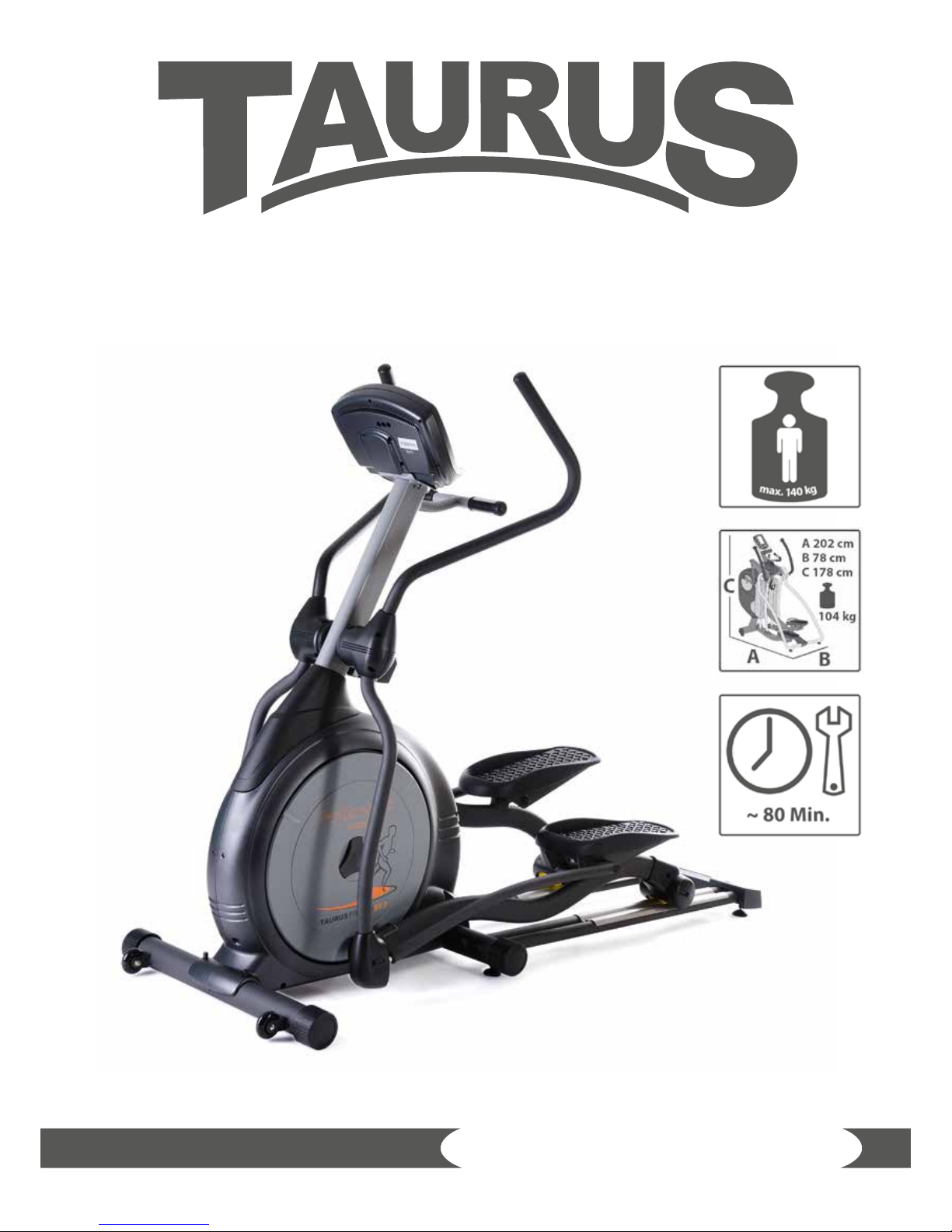
Balance mass: 19,6 kg
Transmission ratio: 1 : 10,3
Operation: generator
Stride length: 50 cm
Maximum user height: 200 cm
Weight and dimensions:
Article weight (gross, incl. packaging): 111 kg
Article weight (net, without packaging): 104 kg
Packaging dimensions (L x W x H): approx. 1460 mm x 540 mm x 830 mm
Set-up dimensions (L x W x H): approx. 2020 mm x 780 mm x 1780 mm
Maximum user weight: 140 kg/ 309 lbs
Page 7

7
1.2 Personal safety
+ Before you start using the equipment, you should consult your physician that
this type of exercise is suitable for you from a health perspective. Particularly
aected are persons who: have a hereditary disposition to high blood pressure
or heart disease, are over the age of 45, smoke, have high cholesterol values, are
overweight and/or have not exercised regularly in the past year.
+ Please note that working out excessively can seriously damage your health. Please
also be aware that heart rate monitoring systems might be imprecise.
+ The equipment may only be used for its intended purpose; that means for whole
body workouts for adults.
+ Any other usage is prohibited and potentially dangerous. The contract partner
cannot be held liable for damage resulting from improper use.
+ The equipment is strictly for use by one person at a time.
+ Children should not be allowed unsupervised access to the equipment.
+ Before starting your training, make yourself familiar with all of the equipment‘s
functions and setting options. Have an expert explain the correct usage of the
product to you.
+ Make sure that nobody is in the range of motion of the equipment while exercising.
+ Keep your hands, feet and other body parts, hair, clothing, jewelry and other
objects well clear of moving parts.
+ During use, wear suitable sports clothing rather than loose or baggy clothing.
When selecting sports shoes, think about the suitability of the sole – preferably
this should be made of rubber or other non-slip materials. Shoes with heels,
leather soles, studs or spikes are not suitable. Never work out in bare feet.
+ It is also important to take note of the information given in the workout instructions
for creating a training plan.
+ At the rst signs of weakness, nausea, dizziness, pain, diculty in breathing or
other abnormal symptoms, stop your workout immediately and, if necessary,
consult your physician.
+ Without prior agreement from your authorized contract partner, opening the
equipment is prohibited.
Page 8

X7.7
8
1.3 Electrical safety
+ The machine requires a network connection of 220 - 230V with 50 Hertz mains
voltage.
+ The equipment should be connected directly to a grounded plug socket only by
means of the power cable supplied. The use of multi-socket adapters or similar
is not recommended. Extension leads must comply with local electrical safety
guidelines. Always fully unwind the power cable.
+ The outlet should be secured with a fuse with a minimum value of „16 amperes,
slow“.
+ In order to reduce the risk of an electric shock, always unplug the equipment from
the mains socket immediately after your workout, before assembly or dismantling,
and before maintenance or cleaning. Do not pull on the cable.
+ When plugged in, do not leave the equipment unattended at any time. To avoid
use by anyone unfamiliar with the operating instructions, the power cable should
be removed when the equipment is not in use.
+ Keep the power cable away from heat, oil and sharp edges. Do not route the power
cable underneath the equipment or under a carpet or rug, and do not place any
objects on top of it.
+ Make no modications to either the power cable or the mains plug.
+ If the power cable or the plug are damaged or defective, contact your authorized
contract partner. Do not use the equipment in the meantime.
+ Do not keep electrical devices (e. g., mobile phones) in close proximity to the
console or the control electronics, otherwise display values (e. g., pulse measuring)
could be inaccurate.
1.4 Set-up place
+ The equipment should only be used indoors, in a suciently heated and dry area
(ambient temperature between 10°C and 35°C). The equipment should not be
used outdoors or in rooms with high humidity (over 70%) like swimming pools. The
equipment should only be stored in surroundings with an ambient temperature
between 5°C and 45°C.
+ The training room should be well ventilated during training and not be exposed to
any draughts.
+ Choose a location in which to place the equipment such that there is enough free
space/clearance to the front, the rear and to the sides of the equipment (at least
1.50 m). Furthermore, the equipment should not be set up in main entrances or on
escape routes.
+ Always keep the power cable away from hot surfaces and grounds and make sure
that the cable is not stuck somewhere or becomes a „trip hazard“.
Page 9

9
+ No objects of any type should be inserted into the openings of the equipment.
+ The equipment should be placed on a level and solid surface, any unevenness in
the oor should be leveled out.
+ A oor protective mat / equipment underlay can help to protect high-quality oor
coverings (parquet, laminate, cork, carpets) from dents and sweat and can help to
level out slight unevenness.
2 ASSEMBLY INSTRUCTIONS, MAINTENANCE AND CARE
2.1 General instructions
+ Please check if all parts and tools belonging to the equipment are included in the
delivery and if there is any transport damage. If there are any complaints, please
contact your contract partner directly.
+ Some of the nuts and bolts to be used in assembly are already pre-mounted in
order to make set-up as easy as possible.
+ The equipment must be assembled by adults. In case of doubt, ask for assistance
from another person with technical skills.
+ Keep children away from the equipment during assembly, because small parts are
included in the delivery and may be swallowed.
+ Make sure that you have enough space (at least 1.50 m) in every direction during
assembly.
+ Do not leave any tools and packaging materials like plastic sheeting laying around
to avoid danger of suocation for children.
+ Assemble the equipment on an underlay mat or on the cardboard packaging in
order to avoid damage to the equipment and to the oor (scratches).
+ Before starting assembly, all individual parts should be placed on the oor next to
each other.
+ Read the assembly instructions carefully and assemble the equipment according
to the illustrations. Proceed carefully and cautiously.
+ First loosen all parts and check for their correct tting. Then tighten the screws
using a too.
+ Modications to the design or improper repairs may pose a hazard to the user and
should not be carried out. The product warranty may be void as a result.
+ Only authorized service technicians are permitted to carry out all servicing and/or
repairs – it excludes maintenance and care.
+ Damaged or worn components may impair your safety and the lifespan of
the equipment. You should therefore immediately replace damaged or worn
components. Please contact your contract partner in such a case. The equipment
should no longer be used until it has been repaired. When needed, only use
original Taurus spare parts.
Page 10

X7.7
10
+ Check the tightness of all screw connections once a month.
+ In order to be able to guarantee the constructively dened safety level of this
equipment, we recommend having the equipment regularly maintained (at least
once a year) by specialists (service technicians of your contract partner).
+ The equipment may be cleaned of dust, dirt and sweat using a damp cloth. The
use of solvents should be strictly avoided. Also, make sure that no liquids (e. g.
sweat) get into the openings of the equipment (e. g. console).
2.2 Faults and troubleshooting
The equipment runs through regular quality controls during production. Nevertheless,
errors or malfunctions on the equipment may occur. Individual parts are often the
cause of faults and replacement is usually sucient. Please use the following overview
to see the ve most common errors and how to repair them. If the equipment still
does not work properly, please contact your contract partner.
Problem Cause Solution
Drive discs wobble
or make noises
Drive pulley is loose Tighten nuts
Display does not
work
No plug connection,
power supply not
plugged in
Check all plug connections and
see if the power supply is plugged
in
Footplates are
creaking
Footplates are loose Tighten up the footplate screws
Creaking noises
Screws are loose Check screws are properly
tightened
No pulse reading
• Sources of
interference in the
room
• Using a chest strap:
- Unsuitable chest
strap
- Chest strap is
incorrectly positioned
- Batteries are empty
oder discharged
• Eliminate sources of interference
(e. g. mobile phone, loudspeaker,
etc.)
• Use a suitable chest strap (see
recommended accessories)
• Reposition the chest strap and/or
moisten the electrodes
• Change or charge the batteries
Page 11

11
2.3 Maintenance and service calendar
The following routine work must be done in the specied time intervals:
Part Weekly Monthly Twice a year Annually
Display console C I
Lubricate the moving parts
I
Plastic cover
C I
Screws and cable connections
I
Legends: C = cleaning; I = inspect
Page 12
X7.7
12
3 ASSEMBLY
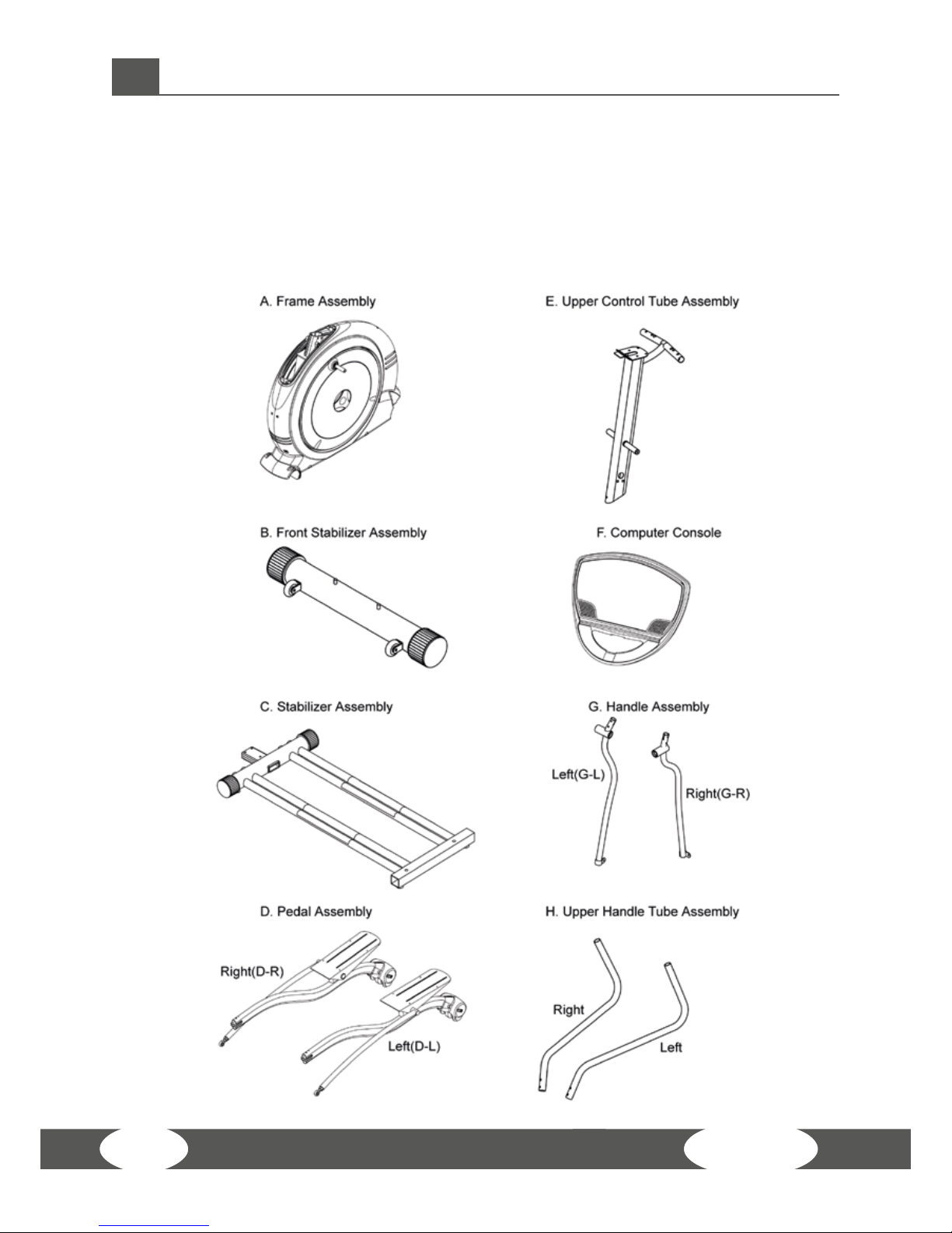
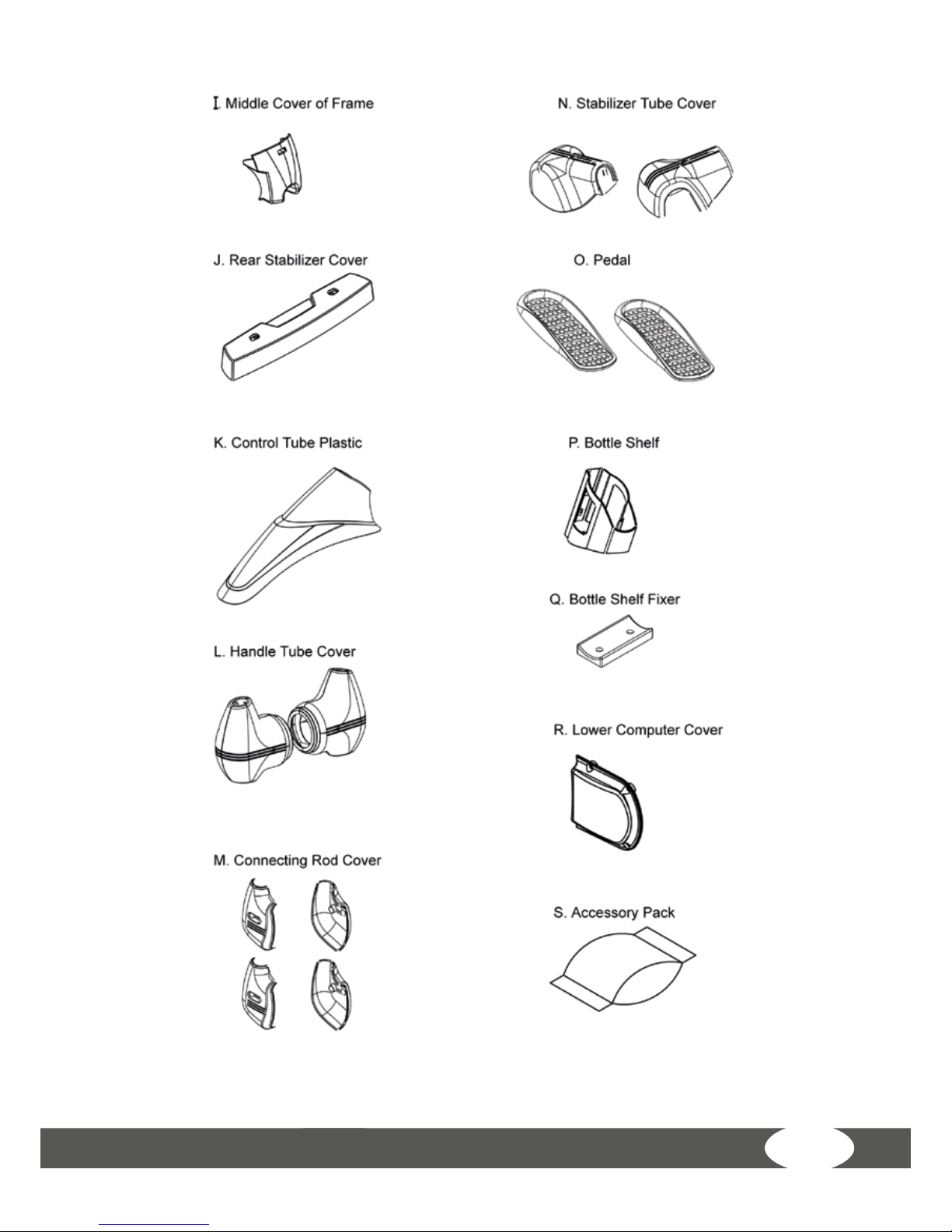
3.1 Package contents
The package contains the parts represented in the illustration, including a power
cable with mains plug. If one of the illustrated parts is missing, please contact your
contract partner.
Page 13
13
Page 14

X7.7
14
Screws and tools
Step Itme Description Qty
1 1 Long Hex Nut 2
2
2 CKS Hex Screw M10x40 Blue Nylonpatch 3
3 Spring Washer M10 3
4 Flat Washer Ø10x Ø20x1.5t 3
3
5 Truss Philips Screw M5x10 1
6 Truss Philips Screw M4x15 2
39 Flat Washer Ø4x Ø10x1.0t 2
4
7 Truss Hex Screw M8x15- Blue Nylonpatch 2
8 Washer Ø8x Ø25x2.0t 2
9 Wave Washer Ø17x Ø24x0.3t 2
5
10 CKS Hex Screw M10x70 2
11 CKS Hex Screw M8x15 1
12 Nylon Nut M10 2
13 Washer Ø8x Ø25x2.0t 1
6
14 Truss Hex Screw M4xP0.7x8 Blue Nylonpatch 4
15 Washer Ø6x Ø13x2.0t 4
16 Acorn Cap Nut M6xP1.0 4
Page 15

15
Step Itme Description Qty
7
17 Truss Hex Screw M8x15 Blue Nylonpatch 2
18 Flat Washer Ø8.5xØ30x2.0t 2
19 Wave Washer Ø26.4x Ø34.2x0.3t 4
20 CKS Hex Screw M12x40 2
21 Nylon Nut M12 2
38 Flat Washer Ø25x Ø35x1.0t 2
8
22 Carriage Screw M8x45 4
23 Nylon Nut M8 4
9 24 Truss Philips Self Tapping Screw Ø5x15 8
10 25 Truss Philips Screw M4x15 6
11
26 Blue Nylonpatch 8
27 Washer Ø6x Ø13x1.0t stainless steel 8
12
28 Truss Philips Screw M6x15 2
29 Washer Ø6x Ø13x1.0t 2
Tools
30 IHex Wrench 75x150<8MM> 1
31 Hex Wrench 10mm 1
32 Hex Wrench 6mm 1
33 Hex Wrench 5x25x67mm 1
34 Hex Wrench +Screwdriver 5x40x180mm 1
35 Bushing Wrench + Screwdriver 13mm+17mm Zinc 1
36 Lug Wrench -19mm+13mm<Galvanization 1
37 Open end wrench 10mm 1
Page 16
X7.7
16
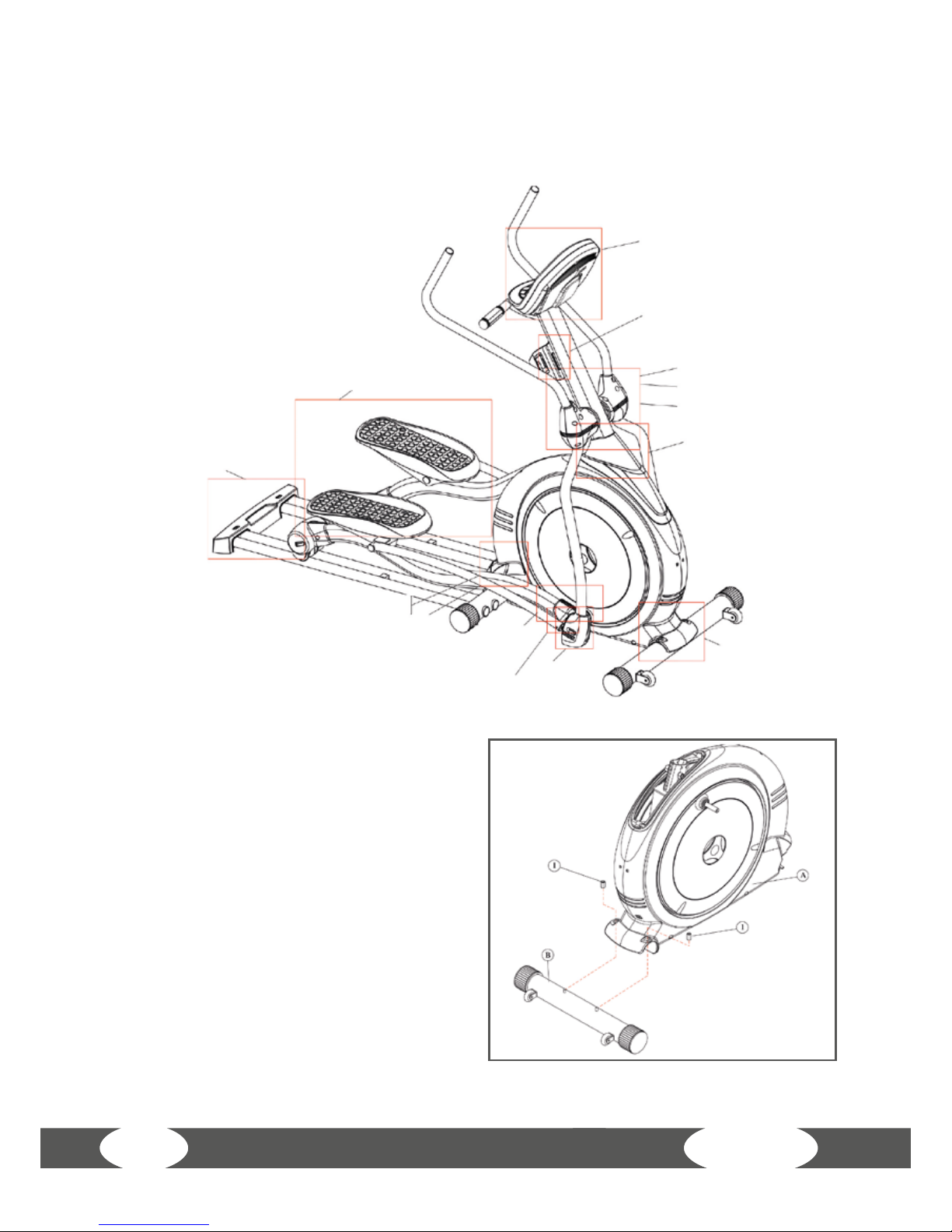
Step 1: Assembly of the frame and the
front base
Mount the frame (A) on the front base
with the screws. Then cover the long
hexagon nuts (1).
Step 1.
Step 9.
Step 10.
Step 3-1.
Step 2.
Step 4.
Step 3-2.
Step 8.
Step 5.
Step 7-2.
Step 7-1.
Step 12.
Step 11.
Step 6.
3.2 Assembly instructions
Before starting assembly, look carefully through the individual assembly steps shown
and assemble the equipment in the order indicated.
Page 17
17
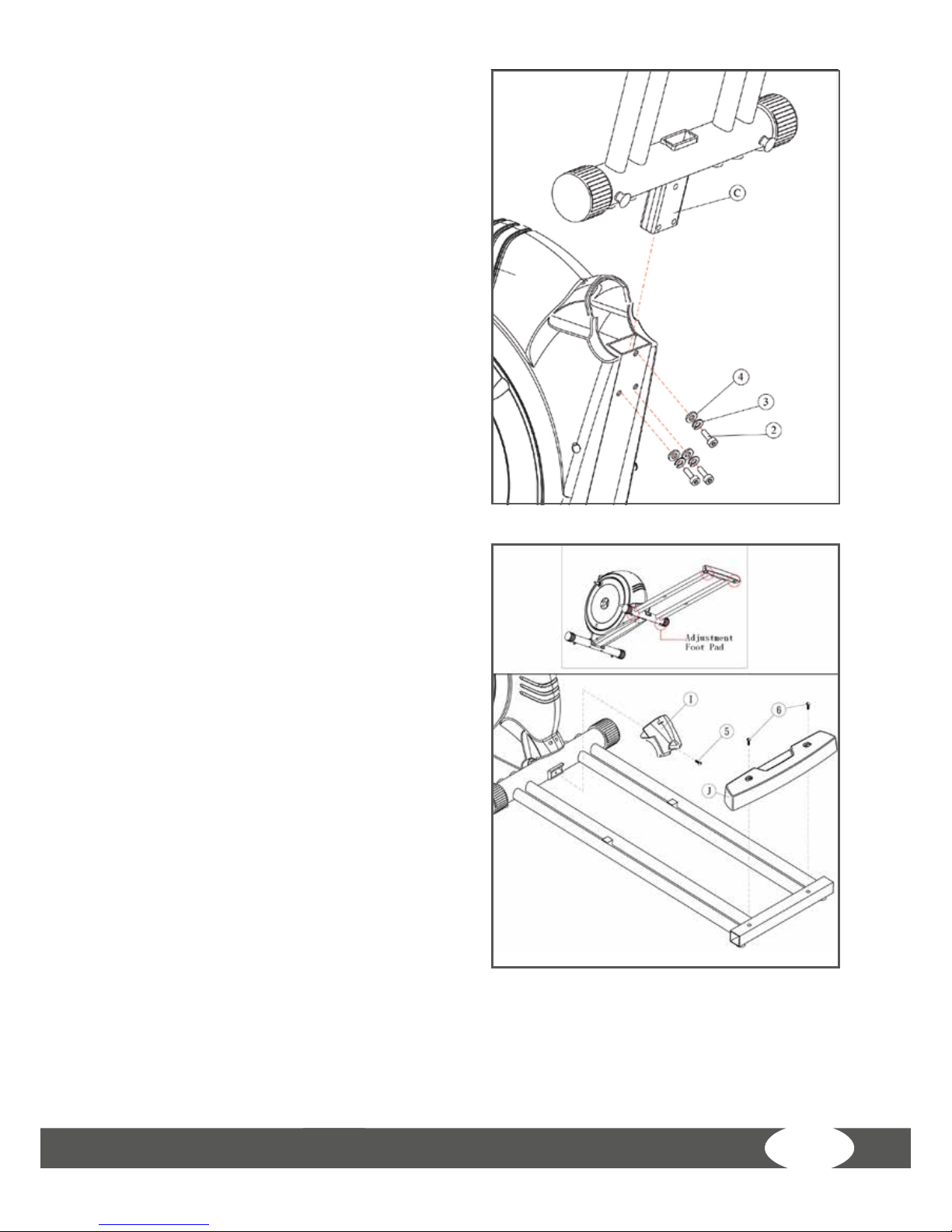
Step 2: Assembly of the frame
Insert the base assembly (C) in the frame
and mount it with the screws (2,3,4).
Step 3: Assembly of the middle cover
and the base
Place the middle cover (I) between the
base assembly and mount it with the
screw (5). Cover the rear cross tube with
the cover (J) and the screws (6).
Attention: After the assembly, make sure
that the centre as well as the rear part of
the equipment stand evenly.
Page 18

X7.7
18
Step 4: Assembly of the pedal components
Place the washer (9) on the crank axle and the left side (D-L) of the pedal assembly on
the left side of the frame crank axle. Then place the washer (8) on it and mount the left
pedal assembly with the screw (7).
Place the washer (9) on the crank axle and the right side (D-R) of the pedal assembly
on the right side of the frame crank axle. Then place the washer (8) on it and mount
the right pedal assembly with the screw (7).
Page 19
19
Step 5: Assembly of the front
frame
Accomplish this assembly step with
two persons if possible. While one
person is holding the front frame
(E) and is putting it in the respective
hole, the other person tightens the
screws.
While tightening the screws, make
sure that none of the screws falls
inside the casing.
Insert the front frame (E) in the
plastics cover (K). Then insert the
front frame (E) in the respective
hole of the main frame (A). Connect
the respective cable endings with
each other. Then press the plastics
cover (K) down, before you mount
the frame with the mounting parts
(10, 11, 12, 13).
Page 20

X7.7
20
Step 6: Assembly of the computer console
Place the pre-drillings behind the computer one on top of the other and mount the
computer (F) with the screws (15, 16). While assembling it, make sure that the computer
is appropriately mounted in order to avoid possible damages to the computer.
Once the computer is assembled, connect all signals. Please pay attention to the
respective directions of connection.
Mount the lower computer cover (R) with the screw (14). Make sure that the cables
do not get clamped. Please also avoid an excessive bending of the cables, because it
might result in damages.
Page 21

21
Step 7: Assembly of the swing arms
1.1: Place the washers (19) next to each other. Then place the handlebar cover (G-L) on
the illustrated tube of the front frame (E). Mount it with the parts (17, 18).
Please pay attention to the dierent sides of the handlebars during the assembly.
Repeat this assembly step for the other side as well (1.3).
Then mount the lower part of the swing arms according to the illustration 1.2
respectively 1.4 with the accessory parts (20, 21) to the pedal components.
Page 22

X7.7
22
Step 8: Assembly of the upper handlebars
Put the upper handlebars (H) on the respective holders of the swing arms and mount
it with the screws (22,23).
Please pay attention to the dierent sides of the handlebars during the assembly as
well.
Page 23
23
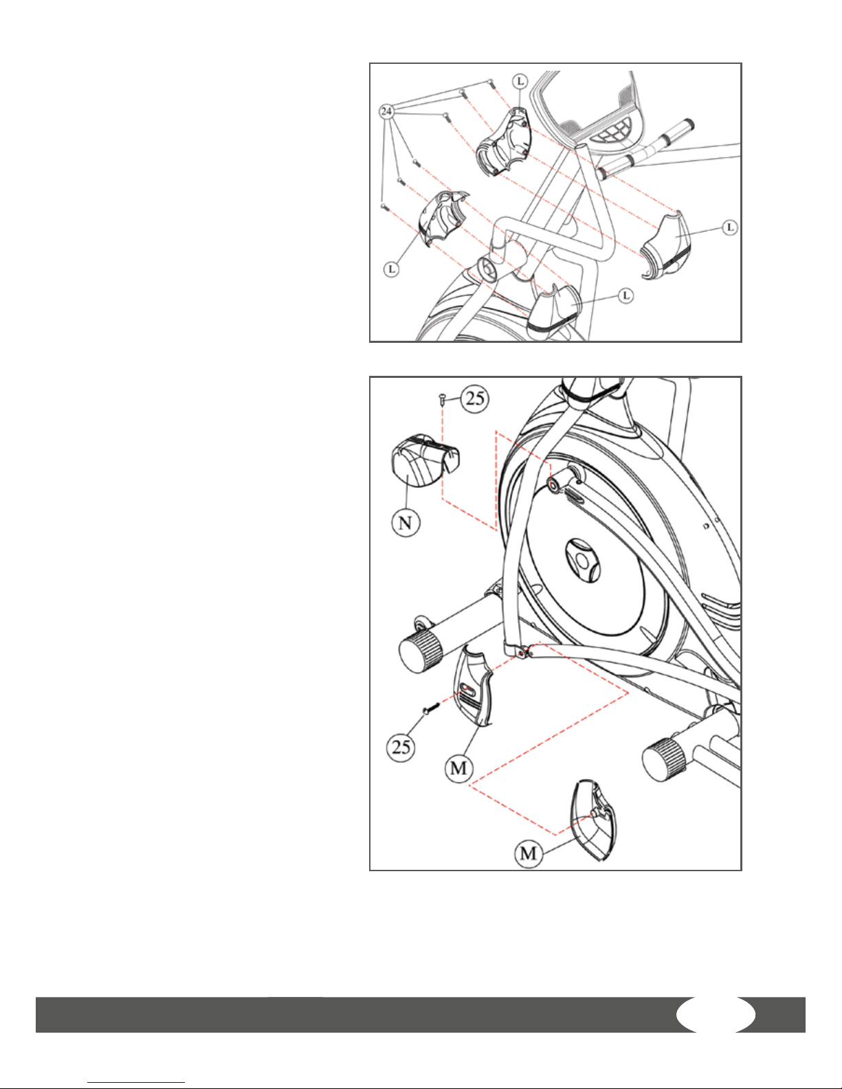
Step 9: Assembly of the plastics
covers (handlebars)
Place the covers (L) on the
equipment according to the
illustration and mount these with
the screws (24).
Make sure that the plastics covers
align and are appropriately
connected.
Step 10: Assembly of the
plastics covers (pedals)
Connect the left and right pedal
cover (N) with the respective
pedal components. Check that all
pre-drillings on the plastics cover
align with those of the steel tube.
Mount it with the screws (25).
Then mount the left and right
cover (M) on the left and right
swing arm. Mount it also with the
screws (25).
Page 24

X7.7
24
Step 11: Assembly of the pedals
Place the pre-drillings of the left pedal (O) on the respective pre-drillings of the pedal
rods. Mount the pedals with the washers (27) and the screws (26).
Repeat this step with the right pedal on the right pedal rods.
Tip: There are directions indicated on the pedals, which are meant to facilitate the
assembly. Please pay attention to these directions provided.
Page 25

25
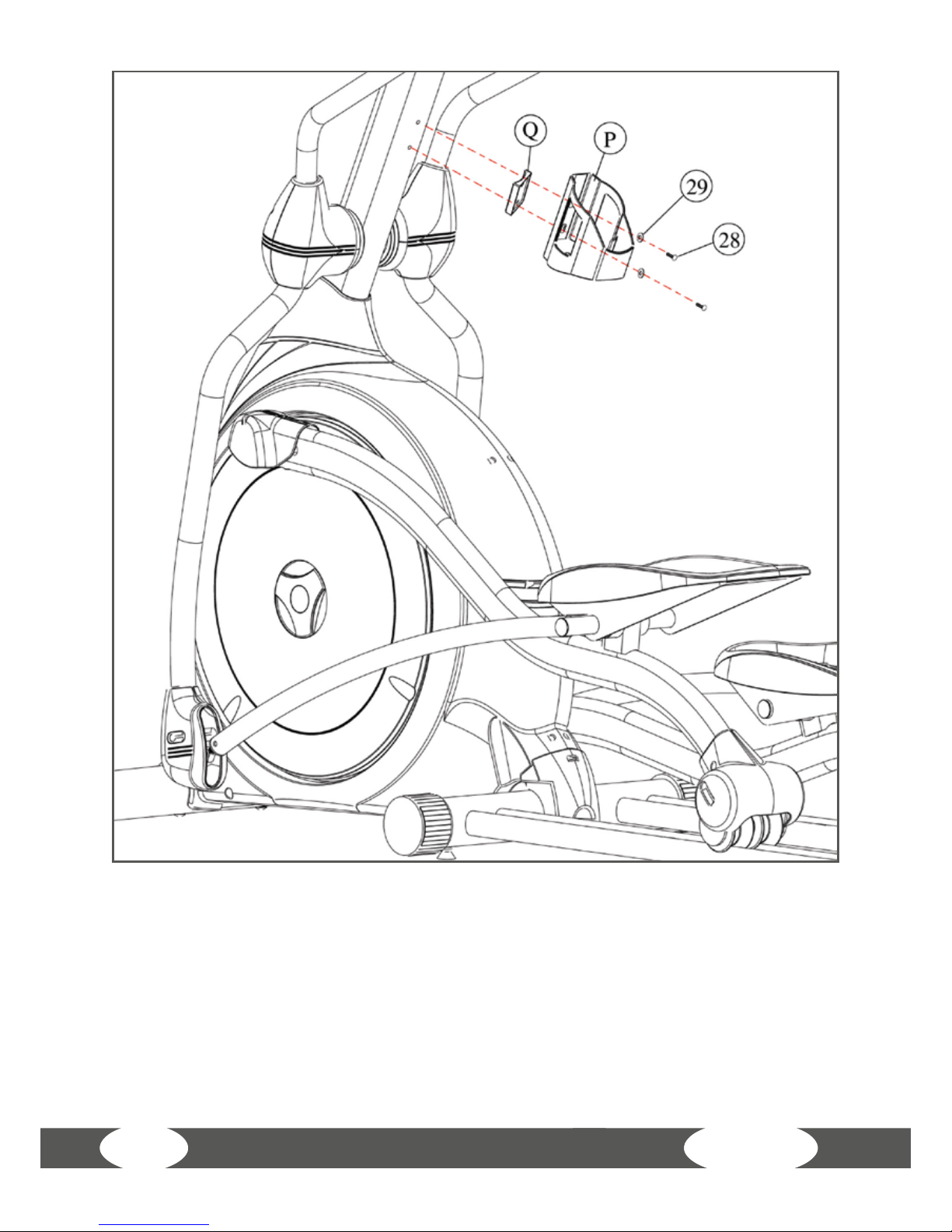
Step 12: Assembly of the cup holder
Mount the cup holder (P) and the xation of the cup holder (Q) on the front frame
construction. Mount it with the sealing washer (29) and the screw (28).
Page 26
X7.7
26
After nishing the assembly, please check again that all screws are
tightened.
Page 27
27
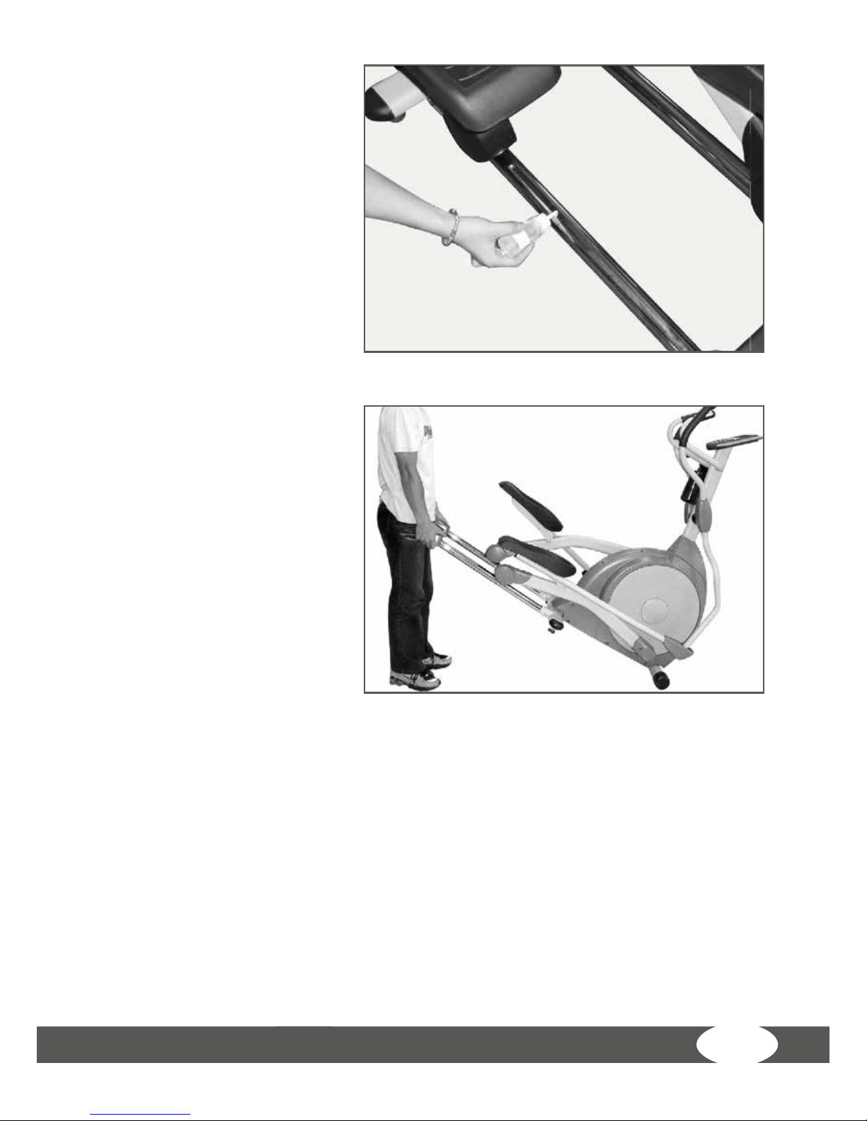
Lubrication
Apply 2 ml of the lubricant
under the middle of the rail. It
is recommended to apply the
lubricant every three months.
When you notice that the
movement is not smooth and
even or noises can be heard,
apply 2 ml of the lubricant in
the middle of the rail.
Transport
The machine is equipped with
transport wheels for an easy
transport of the equipment. Lift
the equipment at the rear end
to move it.
Page 28

X7.7
28
4 OPERATING INSTRUCTIONS
4.1 Console display
CALORIES
Calorie consumption in kcal
Note: Measuring the calorie consumption
The calculation of the energy consumption is done by means
of a general formula. It is not possible to calculate an individual
energy consumption exactly, because a multitude of personal
data is required here. In order to make an approach to your
actual energy consumption possible, you can set your body
weight with this model.
TIME Training time
HEART RATE Heart rate
RPM Speed in rotations per minute
DISTANCE Training distance in km
WORKLEVEL Level of diculty
Page 29

29
WAT T Resistance in watt
METS
Metabolic equivalent (= measure, which is
used for expressing the oxygen cost (oxygen
consumption per unit of body weight), which
is required for accomplishing a task. A MET
corresponds to the approximate metabolism of a
sitting person at rest.
4.2 Button functions
QUICK START Conrm the settings
ENTER Select programmes and set values
RESET Reset all values
+ button Choose proles and increase intensity
- button Choose proles and reduce intensity
Display Shift Switch the display function
Program Proles splay the chosen training prole
4.3 Turning on the equipment
The self power-generating elliptical cross trainer can be placed independently of
sockets. The resistance of this elliptical cross trainer is generated by a continuous
use. The elliptical cross trainer has a low resistance, when the speed is below 60 RPM
(rotations per minute).
Energy save function
The computer is equipped with an energy save function. That means: Once the user
is doing the elliptical movement, the dynamo generates power itself. The provided,
rechargeable 3A batteries of the computer save the generated power and use it when
a speed signal is not received or the training is stopped.
Note: When the equipment is delivered, the batteries are not charged. Please charge
the batteries completely by means of a standard battery charger (charge time of 10
to 20 hours).
Page 30

X7.7
30
Alternatively, you can start the training immediately, so that the batteries are
charged by the self-generated power. Please pay attention to the fact that only
training sessions of 30 minutes and more can inuence the charging of batteries
with a lasting eect.
When the speed signal is no longer received and the training is stopped and the
computer has not been used for more than a minute, the backlight turns o for
one minute. When the computer will not be used after one minute, it turns o
automatically. All values will be reset then.
Start Display:
When you use the equipment, the scrolling text SET WEIGHT is displayed. Press
WEIGHT for entering the weight and then set the body weight (in kg) with the + and –
buttons. Setting the weight serves the calculation of the calorie consumption during
the training session. When the setting is nished, press ENTER.
Now you can choose the type of your training: In order to start with a pre-dened
training programme, select a respective training prole (PROGRAM PROFILES). Press
MANUAL for a manual training. Press QUICK START, when you want to start the training
immediately without a training programme.
4.4 Programmes
Choose one of the following programmes with the control knob:
• Manual programme: 1
• Dierent proles for pre-set training programmes: 4
• Heart rate controlled training programmes: 4
4.4.1 Manual programme
Press MANUAL to get to the manual mode. At rst, the dot matrix displays the lowest
level of diculty. Press ENTER in order to set a training duration. SET TIME is displayed
and you can choose a training time of 1 to 99 minutes with the + and – buttons.
Page 31

31
When you press START in the manual mode, your training starts immediately. The
time counts up starting from 00:00. Throughout the training, you are informed about
time (TIME), covered distance (DIST), speed in rotations per minute (RPM), and burnt
calories (CAL).
Press DISPLAY SHIFT and the values of level of diculty (LEVEL), resistance in watt
(WATT), the metabolic equivalent (METS) as well as your current heart rate (PULSE)
are displayed as well. The latter is only done, when a chest strap is worn for telemetric
heart rate measuring and when the elliptical cross trainer can receive a pulse signal.
The level of diculty can be adjusted by pressing the + and – buttons at any time.
When you have achieved your preferred training duration, that means that the preset training is counted down to 00:00, the computer gets automatically in to the STOP
mode. Here you can look at your training values as well as the training process by
means of the dot matrix for a short time.
Prole of the manual training programme
Page 32

X7.7
32
Random Prole
Weight Loss Prole
Hill Intervals Prole
CV Workout Prole
4.4.2 Training programmes
Choose any pre-set training programme and then set further values (training duration,
etc.).
Proles of the pre-set training programmes
Page 33

33
When you have chosen a pre-set training programme, you have the possibility to do
the training according to certain levels of diculty. Here, 16 pre-saved levels from L1
to L16 are displayed. Press the + or – button to set the preferred level of diculty.
The matrix window displays the process of the training programme. Then press ENTER
to set the time. The default value of the programme is 30 minutes; it can be set from
1 to 99 minutes (in 1-minute increments). After the setting, press ENTER or START to
start the running training.
When you skip the settings of level and time after the selection of the training
programme and press START directly, the non-chosen values are displayed according
to the default values. Throughout the training, you are informed about time (TIME),
covered distance (DIST), speed in rotations per minute (RPM), and burnt calories (CAL).
Press DISPLAY SHIFT and the values of level of diculty (LEVEL), resistance in watt
(WATT), metabolic equivalent (METS) as well as your current heart rate (PULSE) are
also displayed. The latter is only done, when a chest strap is worn for telemetric heart
rate measuring and when the elliptical cross trainer can receive a pulse signal. The
level of diculty can be adjusted by pressing the + and – buttons.
When you have achieved your preferred training duration, that means that the preset training time is counted down to 00:00, the computer gets automatically in to the
STOP mode. Here, you can look at your training values as well as the training process
by means of the dot matrix for a short time.
4.4.3 Heart rate controlled programmes
Press HRC to choose a heart rate controlled programme. Press ENTER until you get to
the selection of your age. When AGE is displayed in the LED display, set your age with
the + and – buttons. The default value is 25 years. Conrm your setting of age with
ENTER. Then the pulse value (PULSE) is displayed on the LED display.
The computer calculates the target pulse depending upon the set age. It is 55% of the
maximum heart rate and is perfect for weight reduction.
When you want to do a tness or cardio training, choose either the HRC programme
70% or 80 % (of the maximum heart rate) or the fourth heart rate controlled programme
(SET HRC) with the + and – buttons. Set your target heart rate independent of the
values mentioned above with the latter one. Use the + and – buttons here as well.
Page 34

X7.7
34
After setting the target heart rate, you can choose the duration of the training
programme with the + and – buttons. The default value of the programme is 30
minutes; it can be set from 1 to 99 minutes (in 1-minute increments). Press ENTER or
START after the setting to start your running training.
Every HRC programme starts with a warm-up phase of two minutes. After it,
BEGINNING HR is displayed and the resistance is slowly adapted so that your target
heart rate is achieved and then constantly kept.
If your pulse cannot be received for 60 seconds or if you have nished your workout,
you return to the START mode.
Proles of the HRC training programmes
Page 35

35
Age
BPM
Age
BPM
Age
BPM
H Base L H Base L H Base L
13 197 124 124 36 175 110 110 59 153 97 97
14 196 124 124 37 174 110 110 60 152 96 96
15 195 123 123 38 173 109 109 61 151 95 95
16 194 122 122 38 172 109 109 62 150 95 95
17 193 122 122 40 171 108 108 63 149 94 94
18 192 121 121 41 170 107 107 64 148 94 94
18 191 121 121 42 169 107 107 65 147 93 93
20 190 120 120 43 168 106 106 66 146 92 92
21 189 119 119 44 167 106 106 67 145 92 92
22 188 119 119 45 166 105 105 68 144 91 91
23 187 118 118 46 165 104 104 69 143 91 91
24 186 118 118 47 164 104 104 70 143 90 90
25 185 117 117 48 163 103 103 71 142 90 89
26 184 116 116 49 162 103 103 72 141 90 89
27 183 116 116 50 162 102 102 73 140 90 88
28 182 115 115 51 161 101 101 74 139 90 88
29 181 115 115 52 160 101 101 75 138 90 87
30 181 114 114 53 159 100 100 76 137 90 86
31 180 113 113 54 158 100 100 77 136 90 86
32 179 113 113 55 157 99 99 78 135 90 85
33 178 112 112 56 156 98 98 79 134 90 85
34 177 112 112 57 155 98 98 80 133 90 84
35 176 111 111 58 154 97 97
BPM = Heart rate = beats per minute
(H): = 95% of the max. heart rate; maximum value for pulse control
(L): = 60% of the max. heart rate; minimum value for pulse control
(Base): = 60-70% of the max. heart rate; recommendable for weight reduction
The following chart shows the relation between age and heart rate.
Page 36

X7.7
36
5 WORKOUT INSTRUCTIONS
5.1 Heart rate measuring
Pulse measuring through hand sensors
The hand sensors integrated in the handles allow you to determine your heart rate.
You can measure your heart rate by lightly grasping the sensors with both hands at the
same time. Blood pressure changes occur due to the heartbeat. The sensors measure
the changes to the electric skin resistance caused by it. These values are then used to
create an average and are displayed on the screen of the console as a heart rate.
Note:
For some people, the skin resistance change caused by the heart rate is so minimal
that the measurements do not allow for usable values. Strong callus or sweat on the
hands may also impair a correct measurement. In such cases, the heart rate will not be
shown at all or only incorrectly.
If the measurement is incorrect or not taken at all, please check if it happens to only
one person or to several people. If the pulse display only does not work in a single
case, the equipment is not defective. In this case, we recommend using a chest strap
to achieve a permanently correct heart rate display.
CAUTION: Your training equipment is not a medical device. Dierent factors
may inuence the accuracy of the heart rate display. The heart rate display only
serves as a training aid.
Telemetric heart rate measuring
This elliptical cross trainer is already equipped with a heart rate receiver as standard.
Using a chest strap makes it possible for you to have a wireless heart rate measuring.
This optimal and ECG-precise type of measuring reads the heart rate directly from the
skin through a transmitting chest strap. The chest strap then sends the impulse to the
receiver integrated in the console.
Positioning the chest strap and moistening the electrodes:
Place the belt directly below the chest, while the transmitter should be placed on the
middle of the chest. The chest strap should sit comfortably, but not too loose. If the
belt is too loose, the contact to the electrodes may be disrupted or the belt may slip
while exercising. The transmitter turns on automatically once it is put on. In order to
allow for a precise measuring, you should moisten the rubber electrodes. This is best
done with a special chest strap contact gel, which is also used for ultrasound scans.
Page 37

37
Note:
If you have not been active in doing sports for a longer period of time, you should
rst go to your physician in order to discuss your training with them. You should also
contact your physician in advance in the event of heart problems, high/low blood
pressure and obesity.
Training with heart rate orientation
Heart rate orientation guarantees an extremely eective and healthy training. Through
your age and the following table, you can quickly and easily read and determine the
optimal pulse for your training. An alarm will sound if your heart rate exceeds the set
target heart rate. Which target heart rate is important for which training goal can be
found out in the following.
Fat burning (weight management): The main goal here is to burn deposits of fat. In
order to achieve this training goal, a low training intensity (approximately 55% of the
maximum heart rate) and a longer training period are required.
Cardiovascular training (cardio training): The primary goal is to increase stamina
and tness through an improved provision of oxygen through the cardiovascular
system. In order to achieve this training goal, medium intensity (approximately 75%
of the maximum heart rate) with a medium training period is required.
Anaerobic (maximum) load training: The main goal of maximum load training is to
improve recovery after short, intense loads in order to be able to quickly return to the
aerobic zone. In order to achieve this training goal, a high intensity (approximately
90% of the maximum heart rate) with short, intense load is required, which is followed
by a recovery phase in order to prevent muscle fatigue.
Page 38

X7.7
38
Example:
For a 45-year-old man or woman, the maximum heart rate is 175 (220 - 45 = 175).
• The fat burning target zone (55%) is at approximately 96 beats/min.
= (220 - age) x 0.55.
• The cardio target zone (75%) is at approximately 131 beats/min.
= (220 - age) x 0.75.
• The maximum heart rate for an anaerobic load training (90%) is at approximately
157 beats/min. = (220 - age) x 0.9.
20
80
100
120
140
160
180
200
220
65 7060555045403525 30
200
195
190
185
180
175
170
180
150
110
146
107
175
171
166
162
157
153
148
143
139
135
131
128
124
105
102
99
96
94
91
88
85
83
113
116
120
144
139
136
150
155
160
165
Heart rate diagram for training intensity
Maximum pulse (220-age)
90% of maximum pulse - anaerobic (maximum) intensity training
75% of maximum pulse - cardiovascular training (cardio training)
55% of maximum pulse - fat burning (weight control)
Heartbeats
Age
Page 39

39
5.2 10 tips for eective elliptical cross training
1. Set goals
What would you like to achieve with your training? Weight regulation, improved
stamina, prevent risk of disease, more mobility, cardiovascular training, etc. In order
to achieve your long-term training goal, set individual partial goals, e. g., weekly or
monthly goals.
2. Concentration on training
Try to only dedicate yourself to your training session and do not be distracted.
3. Position yourself correctly while exercising
When you execute the movement, you should start with a moderate speed and hold on
if needed. The speed can then be increased gradually. The adjustment of your natural
running style will occur relatively quickly. Beginners and overweight people should
start with a walking program in order to not overload their joints in the beginning.
4. Correct breathing / appropriate resistance level
Do not overexert yourself physically and mentally by starting with resistance levels
that are too high. Start slowly and increase the resistance steadily. Aim for regular and
calm breathing.
5. Keep yourself properly hydrated
Drink, drink, drink! Have a drinking bottle close by during your workout.
6. Sucient recovery periods
Allow your body and your muscles enough time to recover after your workout. Only a
relaxed muscle will be fully operational again.
7. Choose a diversied program
Dierent program functions from your training console support you in doing this. For
example, you can complete an interval, incline or step number training unit.
8. Creating the right workout
Every training session should have a warm-up phase, a cool-down phase and a
targeted stretching. It increases physical and mental performance and prevents
injuries and sore muscles.
Page 40

X7.7
40
9. Workout journal
Keep a record of your training sessions. Note the date, resting pulse, active pulse, recovery
pulse, resistance level, time, distance, calories burnt and tness level.
10. Reward yourself
Do something good for you and your body after training or after achieving a partial goal.
Go to the sauna or a swimming pool. Mix a protein shake or enjoy a delicious salad.
5.3 Designing a workout
We recommend two or three workouts per week. Warm up for about ve minutes before
starting each workout. Finish the workout with a cool-down and targeted stretching.
Warm-up approx. ve min. Dynamic movement of large muscle groups at a
low intensity. Core body temperature increases
and the metabolic process is speeded up.
WEEK 1 + 2
Beginner Advanced
Days Duration Intensity Duration Intensity
Mon 20 min. Slow speed without
resistance
30 min. Moderate speed, keep
resistance low
Wed 20 min. Slow speed without
resistance
30 min. Moderate speed, keep
resistance low
Fri 20 min. Slow speed without
resistance
30 min. Moderate speed, keep
resistance low
In the rst week, increase the speed in
between for two-minutes. Maintain heart
rate.
In the second week, increase the speed for
brief periods.
WEEK 3 + 4
Beginner Advanced
Days Duration Intensity Duration Intensity
Mon 25 min. Slow speed without
resistance
35 min. Vary speed, keep resistance
low
Wed 25 min. Slow speed without
resistance
35 min. Vary speed, keep resistance
low
Page 41

41
Fri 25 min. Slow speed without
resistance
35 min. Vary speed, keep resistance
low
In the third week, increase the resistance
slightly.
In the fourth week, combine forwards
and backwards movements.
WEEK 5 + 6
Beginner Advanced
Days Duration Intensity Duration Intensity
Mon 30 min. Moderate speed, keep
resistance low
40 min. Vary speed, keep resistance
low
Wed 30 min. Moderate speed, keep
resistance low
40 min. Vary speed, keep resistance
low
Fri 30 min. Moderate speed, keep
resistance low
40 min. Vary speed, keep resistance
low
In the fth week, increase the resistance
slightly at moderate speed.
In the sixth week, alternate between
forwards and backwards movements.
WEEK 7 + 8
Beginner Advanced
Days Duration Intensity Duration Intensity
Mon 35 min. Vary speed, keep
resistance low
45 min. Vary speed, increase
resistance
Wed 35 min. Vary speed, keep
resistance low
45 min. Vary speed, increase
resistance
Fri 35 min. Vary speed, keep
resistance low
45 min. Vary speed, increase
resistance
In the seventh week, include short sprints. In the eighth week, alternate between
forwards and backwards movements.
Cool-down approximately 5 min. Finish your training at low resistance and
at slow speed. Allow your body to gently
slow back down.
Page 42
X7.7
42
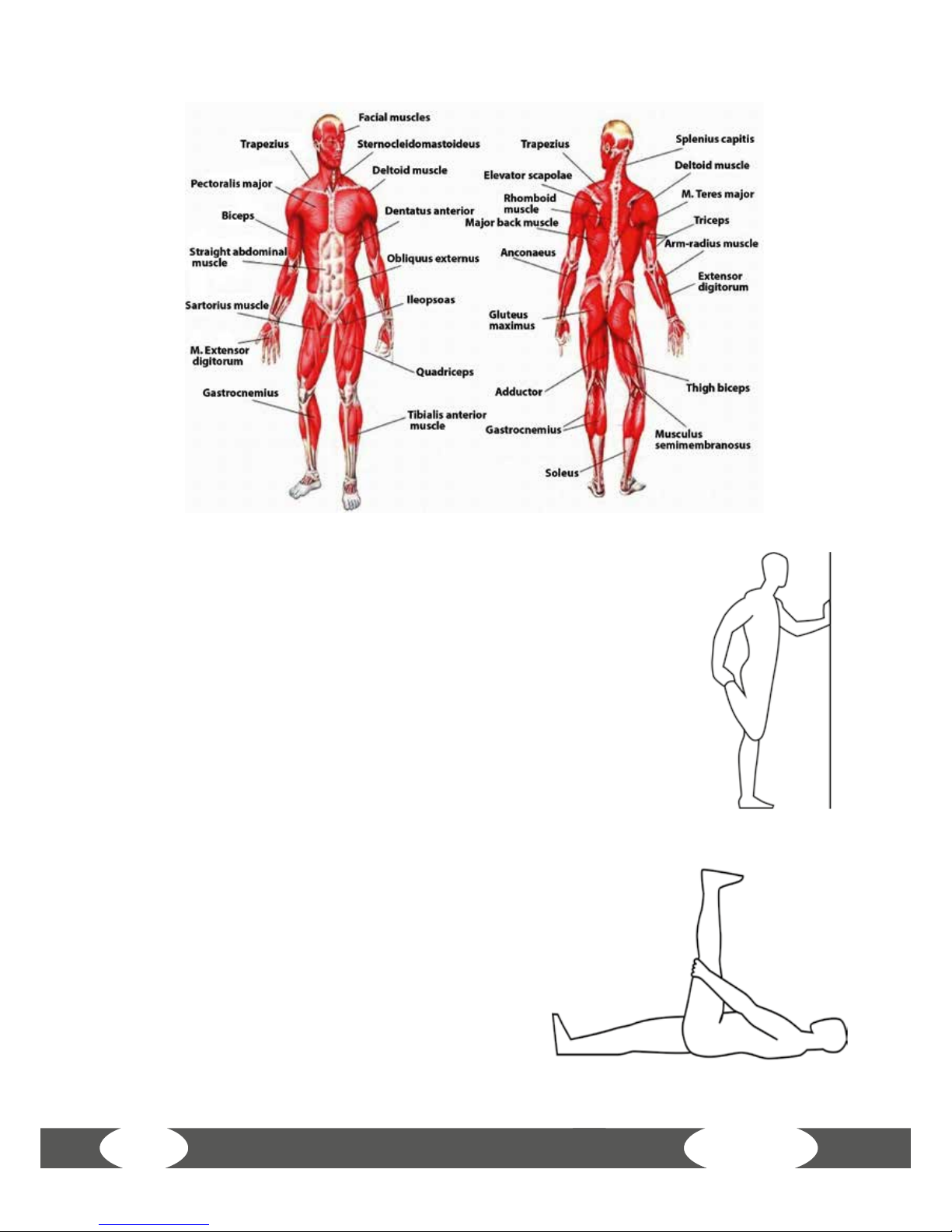
5.4 Stretching exercises for leg & chest muscles
1. Exercise: Stretching of front thigh / leg extension (quadriceps)
• Stable position, grab arches of feet
• Pull heel towards buttocks, knee points downwards
(no abduction)
• Straight upper body, avoid tilting the pelvic forward
(hollow back) by tensing the abdominal muscles
• Change legs
2. Exercise: Stretching the back thigh / leg curl (hamstring)
• Pull thigh towards upper body with both
hands
• Stretch through increased stretching in
the knee joint
• The lower leg maintains contact with the
oor, keep hips bent
• Change legs
Page 43

43
3. Exercise: Stretching the calf muscles (gastrocnemius)
• Place feet parallel to each other pointing forward,
the heels touch the oor
• Support yourself on a chair coming from a lunge
• Move your body weight to the front leg, press
your heel from the rear leg towards the oor and
hold the contact
• Slowly stretch your knee of the rear leg until you
feel the stretch in your calves
• Change legs
4. Exercise: Stretching the chest muscles (pectoralis major)
• Stand parallel to a wall
• Place your forearm at 90° to the wall with the elbow
just above shoulder height
• Turn your head and upper body gradually to the
opposite sides until you feel a stretch in the front
chest, of the shoulder being leaned on
• Pay attention to tension in your abdominal and
gluteal muscles
• Your weight is on your front leg
• Change legs
All recommendations of these instructions apply solely to healthy persons and
are not suitable for those with heart or cardiovascular problems. All of the tips
are intended only as a guide to help you create a workout. Your physician can
oer appropriate advice for particular, personal requirements.
We hope you enjoy your workout and have a lot of success!
Page 44

X7.7
44
5.5 Workout journal
Date
Training weight
Time (min.)
Calories burnt Body weight
Distance
Ø Pulse
Resistance level
I feel ...
(Copy template)
Page 45

45
6 WARRANTY INFORMATION
Taurus training tness equipment is subject to strict quality controls. However, if a
tness equipment purchased from us does not work perfectly, we take it very seriously
and ask you to contact our customer service as indicated. We are happy to help you by
phone via our service hotline.
Error descriptions
Your tness equipment is developed for long-term, high-quality training. However,
should a problem arise, please rst read the operating instructions. For further
assistance, please contact your contract partner or call our service hotline. To ensure
your problem is solved as quickly as possible, please describe the defect as exactly as
possible.
In addition to the statutory warranty, we provide a warranty for every tness
equipment purchased from us according to the following provisions.
Your statutory rights are not aected.
Warrantee
The warrantee is the rst/original buyer and/or any person who received a newly
purchased product as a gift from the original buyer.
Warranty periods
The following warranty periods begin on delivery of the tness equipment.
Model Use Full warranty Frame
X7.7
Home use 24 months 30 years
Semiprofessional use 12 months
Repair costs
According to our choice, there will either be a repair, a replacement of individual
damaged parts or a complete replacement. Spare parts, that have to be mounted
while assembling the equipment, have to be replaced by the warrantee personally
and are not a part of repair. After the expiration of the warranty period for repair costs,
a pure parts warranty applies, which does not include the repair, installation and
delivery costs.
Page 46

X7.7
46
The terms of use are dened as follows:
• Home use: solely for private use in private households up to 3 hours per day
• Semi-professional use: up to 6 hours per day (e. g. rehabilitation centers, hotels,
clubs, company gyms)
• Professional use: more than 6 hours per day (e. g. commercial gyms)
Warranty service
Within the warranty period, equipment which develops faults as a result of material
or manufacturing defects, will be repaired or replaced at our discretion. Ownership
of equipment or parts of equipment which have been replaced is transferred to us.
The warranty period is not extended nor does a new warranty period begin following
repair or replacement under the warranty.
Warranty conditions
For the warranty to be valid, the following steps must be taken:
Please contact our customer service by email or phone. If the product under warranty
has to be sent in for repair, the seller bears costs. After expiry of the warranty, the buyer
bears the costs of transport and insurance. If the fault is covered by our warranty, you
will receive a new or repaired equipment in return.
Warranty claims are invalid in case of damage resulting from:
• misuse or improper handling
• environmental inuences (moisture, heat, electrical surge, dust, etc.)
• failure to follow the current safety measures for the equipment
• failure to follow the operating instructions
• use of force (e. g. hitting, kicking, falling)
• interventions which were not carried out by one of our authorized service centers
• unauthorized repair attempts
Proof of purchase and serial number
Please make sure that you are able to provide the appropriate receipt when claiming
on your warranty. So that we can clearly identify the model of your equipment, and
for the purposes of our quality control, you will need to give the serial number of
your equipment, when contacting the service team. Where possible please have your
serial number and your customer number ready when you call our service hotline. It
will help us to deal with your request swiftly.
Page 47

47
If you have trouble nding the serial number on your tness equipment, our service
team is at your disposal to oer further information.
Service outside the warranty period
We are also happy to issue an individual cost estimate if there is a problem with your
tness equipment after the warranty has expired, or in cases which do not fall under
the terms of the warranty, e. g. normal wear and tear. Please contact our customer
service team to nd a quick and cost-eective solution to your problem. In such a case
you will be responsible for the delivery costs.
Communication
Many problems can be solved just by speaking to us as your contract partner. We
know how important it is to you as a user of the tness equipment to have problems
solved quickly and simply, so you can enjoy working out with minimal interruption.
For that reason, we also want to resolve your queries quickly and in a straightforward
manner. Thus, please always keep your customer number and the serial number of
the faulty equipment handy.
7 DISPOSAL
At the end of its operational life, this equipment cannot be disposed
of in normal household waste. Instead, it must be disposed of via an
electricals recycling centre. Further information can be obtained from
your local authority‘s recycling service.
The materials can be recycled as per their symbols. Through the reuse, recycling of
materials or other forms of recovery of old equipment, you make an important contribution to the protection of the environment.
Page 48

X7.7
48
8 ORDERING ACCESSORIES
Sport-Tiedje oor mat XL
Art. No. ST-FM-XL
Sport-Tiedje transmitter chest strap
Art. No. ST1000
Sport-Tiedje Komfort chest strap
Premium
Art. No. ST1050
Chest strap electrode gel 250ml
Art. No. BK-250
Fitness equipment care set
Art. No. HF-500
Page 49

49
9 ORDERING SPARE PARTS
9.1 Service hotline
So that we can give you the best possible service, please have your model name, part
number, serial number, exploded drawing and parts list ready.
SERVICE-HOTLINE
9.2 Serial number and model name
Before assembling your equipment, nd the serial number on the white sticker and enter
it in the appropriate space.
Serial number:
Brand / category: Model name:
Taurus elliptical cross trainer X7.7
+31 172 619961
info@tshop.nl
Ma. - Do. 9:00 - 17:00
Vr. 9:00 - 21:00
Za. 10:00 - 17:00
+33 (0) 172 770033
+49 4621 4210-933
service-france@sport-tiedje.fr
Lun. - Ven. 8:00 - 18:00
Sam. 9:00 - 18:00
80 90 16 50
+49 4621 4210-945
info@t-tness.dk
Ma. - Fr. 8:00 - 18:00
Lø. 9:00 - 18:00
+44 141 876 3972
orders@powerhousetness.co.uk
Mon. - Fri. 9:00 - 17:00
+49 4621 4210-0
service-int@sport-tiedje.de
Mon - Fri 8:00 - 18:00
Sat 9:00 - 18:00
+49 4621 4210-0
+49 4621 4210-699
service@sport-tiedje.de
Mo. - Fr. 8:00 - 18:00
Sa. 9:00 - 18:00
DE
NL
DK
UK
FR
INT
Page 50

X7.7
50
9.3 Parts list
No Qty. Part number Description
(A) Main Frame and Assembly Fittings
A01 1 JEA2-A1001 Frame Assembly
A02 1 EA1-C1001 Grank Set Assembly
A03 1 JEA1-D1002 Idler Wheel Assembly
A04 1 PCT-002-1 Belt Wheel(big) Φ310<J8 for belt>, including sensor magnet
NF-061
A05 4 SGA8-20I CKS Hex Screw M8xP1.25x20
A06 4 SOC8 Nylon Nut M8xP1.25
A07 1 CA-490J8 Belt 49" J8
A08 1 NS-122 Idler Wheel Spring
A09 4 GH-6204ZZ Bearing 6204ZZ
A10 1 SRA20 C Shaped Ring for Φ20 Post
A11 1 NT-1633 Inner Belt Wheel Bushion
A12 1 SK-469 M20xP1.0 Nylon Nut
A13 1 NFW-004(NT-1683) Generator Φ242 small belt wheel Φ30 10J B600321A (including
post cover)
A14 4 SGA6-20 CKS Hex Screw M6xP1.0x20
A15 4 SPB6 Spring Washer M6
A16 4 SPA060-130-10 Washer Φ6xΦ13x1.0t
A17 3 NT-1489 IDLER PAD
A18 3 SIA5-15IL Counter Sink Hex Screw M5xP0.8x15 blue nylok
A19 1 SGA8-25I CKS Hex Screw M8xP1.25x25
A20 1 SGA8-30I CKS Hex Screw M8xP1.25x30
A21 1 XRB-037-003 Lower PC board 040901
A22 2 SAE5-12 Round Head Philips Screw M5xP0.8x12
A23 6 BJ-48-330B binding 4.8X330mm black
A24 1 BJ-22-080B binding 2.2X80mm black
A25 1 BJ-36-102B binding 3.6X102mm black
A26 1 DFA017-035-0080 HDR Foam GripΦ17xΦ24x80mm
A30 1 NT-2439 crankshaft socket
(B) Front Base Tube Assembly (1 set)
B01 1 JEB1-B1001 Front Base Tube Assembly
Page 51

51
No Qty. Part number Description
B02 2 PCB-75-001 outside cover tube Ø75 吾吾(FC012)
B03 2 NT-2318 Long Allen Nut
B04 2 SDA8-45 Truss Hex Screw M8xP1.25x45
B05 2 SOC8 Nylon Nut M8xP1.25
B06 2 SPA080-160-20 Washer Φ8xΦ16x2.0t
B07 2 PB-01-002 Bearing wheel (non-bearing)Φ70XΦ8X28t
(C) Cover (1 set)
C01 1 P-1506L Left Frame Cover
C02 1 P-1506R Right Frame Cover
C03 2 NO-3141 Plastic Iron Fixing Plate
C04 1 NO-3141A Plastic Iron Fixing Plate-short
C05 2 SPA060-160-10 WasherΦ6xΦ16x1.0t
C06 10 SCA5-10 Truss Philips Screw M5xP0.8x10
C07 2 SCA5-12 Truss Philips Screw M5xP0.8x12
C08 4 SCI5-12 Truss Philips Self Tapping Screw Φ5x12
(D) Turn Plate Cross Fittings (1 set)
D01 2 JEA1-G1001 Turn Plate Cross Assembly
D02 2 P-1504 Plastic Turn Plate
D03 16 SCI5-15 Truss Philips Self Tapping Screw Φ5x15
D04 2 SOB14-P15-10T Nut(washer shaped) M14xP1.5x10t
D05 2 P-1505 Turn Plate Cover
(E) Rear Leg Tube Assembly (1 set)
E01 1 JED5-I1002 Rear Leg Tube Assembly
E02 2 SOA8 Allen Nut M8xP1.25
E03 4 P-1820 Adjustment Foot Pad
E04 2 PCB-75-001 Outside cover tube Φ75 (FC012)
E05 1 P-1972 Rear Leg Tube Cover
E06 4 PCA-1-1/2-003 Flat cover tube φ1-1/2"x2.0t (BC-218-1)
E07 3 SK-463 CKS hex screw M10xP1.5x40 blue nylok
E08 3 SPB10 Spring washer M10
E09 3 SPA100-200-15 Flat washer Φ10xΦ20x1.5t
E10 2 SCA4-15 Truss philips screw M4xP0.7x15
E11 2 AAL208E0620-001 Wheel Plate
Page 52

X7.7
52
No Qty. Part number Description
E12 4 SDA8-15 Truss hex screw M8XP1.25X15
E13 4 SOC8 Nylon nut M8
E14 4 BAA0600-250-15 Foam 600mmx25mmx1.5t
(F) Iron Stabilizer Tube and Fittings (1 set)
F01 2 JEA3-M1001 Iron Stabilizer Tube Assembly
F02 16 GH-6003ZZ Bearing 6003ZZ
F03 2 NT-1557 Wheel Fixing Bushion
F04 8 A4B020E00072-001 Post<short> Φ18XΦ23.7X7.2
F05 2 SPG170-240-03 Wave Washer Φ17xΦ24x0.3t
F06 2 SK-443 Fixing Screw M8XP1.25X135 <-15>
F07 4 SOC8 Nylon Nut M8xP1.25
F08 4 P-1728B PU Wheel Φ74X44
F09 2 JEA1-J1001 Front Pedal Fixing Plate Assembly
F10 2 SGA8-85IL CKS Hex Screw M8XP1.25X85<=30mm> blue nylok
F11 4 NO-2014 Arc Washer
F12 2 NT-1560 Plastic Core of Iron Stabilizer Tube
F13 2 P-1516L Left Wheel Cover
F14 2 P-1516R Right Wheel Cover
F15 4 SCA4-15 Truss Philips Screw M4xP0.7x15
F16 2 SDA8-15L Truss Hex Screw M8xP1.25x15-blue nylok
F17 2 SPA080-250-20 Washer Φ8xΦ25x2.0t
F18 2 SPG170-240-03 Wave washer Φ17xΦ24x0.3t
(G) Upper Control Tube Set (1 set)
G01 1 (G) Upper Control Tube Set Upper Frame Assembly
G02 2 SGA10-70I CKS Hex Screw M10xP1.5x70
G03 1 SGA8-15I CKS Hex Screw M8xP1.25x15
G04 2 SOC10 Nylon Nut M10xP1.5
G05 1 SPA080-250-20 Washer Φ 8x Φ 25x2.0t
G06 2 BE-0300 Binding L=300 black
(H) Contact Hand Pulse Set (1 set)
H01 4 P-1080 Hand Pulse Sensor Base
H02 4 NO-2432 Hand Pulse Sensor Plate
H03 4 BAC0750-250-03 Double Sided Tape 25mmx75mmx0.3t
Page 53

53
No Qty. Part number Description
H04 4 SAA3-30 Round Head Philips Screw M3xP0.5x30
H05 4 SOA3 Allen Nut M3xP0.5
H06 2 P-1712 Tube End-Φ1-1/4"
(I) Handrail Set (1 set)
I01 1 JEA2-Q2001 Left Handrail Tube Assemly
I02 1 JEA2-Q1001 Right Handrail Tube Assemly
I03 4 GH-6305VV Bearing 6305VV
I04 1 JEB1-Q2001 Left Upper Handrail Tube
I05 1 JEB1-Q2002 Right Upper Handrail Tube
I06 2 PFA-031-03-970 HDR Foam GripΦ31X3.0tX970 (left&right)
I07 2 P-1712 Tube Cap-Φ1-1/4"
I08 2 SDA8-15L Truss Hex Screw M8xP1.25x15-blue nylok
I09 2 SPA085-300-20 Flat washer Φ8.5XΦ30X2.0t
I10 4 SNA8-45 Screw M8XP1.25X45
I11 4 SOC8 Nylon Nut M8xP1.25
I12 4 SPG264-342-03 Wave washer 26.4x34.2x0.3t
(J) Connecting Rod Set (1 set)
J01 1 JEA2-R1001 Right Connecting Rod Assembly
J02 1 JEA2-R2001 Left Connecting Rod Assembly
J03 2 GH-POS12-R Universal Post-POS12-R(Φ12)
J04 4 SOC12 Nylon Nut M12xP1.75
J05 2 BAA0900-900-30 Foam Sticker 90X90X3.0t (one side plastic)
J06 2 NT-1483 Axle
J07 4 SGA8-15L CKS Hex Screw M8XP1.25X15 blue nylok
J08 2 P-1651 Plastic Washer
J09 4 P-1393 Tube End
J10 4 SPA085-190-20 Washer Φ8.5xΦ19x2.0t
J11 2 SGA12-40I CKS Hex Screw M12xP1.75x40
J12 2 SGA6-10L CKS Hex Screw blue nylok M6xP1.0x10
(K) Plastic Attachments (1 set)
K01 1 P-1507 Middle Frame Cover
K02 1 P-2564 Left Pedal Steel Plastic
K03 1 P-2565 Right Pedal Steel Plastic
Page 54

X7.7
54
No Qty. Part number Description
K04 1 P-2559 Handle bar front plastic (Left)
K05 1 P-2558 Handle bar rear plastic (Left)
K06 1 P-2561 Handle bar front plastic (Right)
K07 1 P-2560 Handle bar rear plastic (Right)
K08 2 P-2566 Left Tube Plastic
K09 2 P-2567 Right Tube Plastic
K10 2 P-1519 Pedal <ABS+TPR>
K11 1 P-2562 Upright Tube Shroud
K12 8 SCI5-15 Truss Philips Self Tapping Screw Φ5x15
K13 6 SCA4-15 Truss Philips Screw M4xP0.7x15
K14 8 SCA5-10SL Truss Philips Screw M5xP0.8x10 Stainless Steel, blue nylok
K15 8 SPA060-130-10S Washer Φ6xΦ13x1.0t Stainless Steel
K16 1 SCA5-10 Truss Philips Screw M5xP0.8x10
(L) Computer Console & Wires (1 set)
L01 1 HEA1-T1006-1 Computer Console(including XL-502 upper hand pulse wire &
XL-423 upper controller
L02 4 SOG6 Nut Cap M6XP1.0
L03 4 SPA060-130-10 Nut Cap M6XP1.0
L04 2 XL-270 upper hand pulse wire<lower> handpulse sensor wire 720mm
L05 1 XL-424 Controller Wire <Middle>
L06 1 XL-504 Controller Wire <Down>
L07 1 XL-426 Flywheel Control Cable (A)
L08 1 XL-505 Flywheel Control Cable
(M) Other Fittings (1set)
M01 1 HED5-Y1001 Part Bag
M02 1 P-2119 Bottle Holder
M03 1 P-540D Bottle Holder Base
M04 2 SCA6-15 Truss philips screw M6xP1.0x15
M05 2 SPA060-130-10 Washer ψ6xψ13x1.0t
M06 1 P-1646 monitor decorative cover
M07 4 SCA4-8 Truss philips screw M4xP0.7x8
M08 4 BE-0300 Binding L=300 black
Page 55

55
9.4 Exploded drawing
Page 56

X7.7
56
CONTACT
Company head oce
Sport-Tiedje GmbH
Flensburger Str. 55
24837 Schleswig
Germany
Hotline for Technical Information
DISCLAIMER
©2011 TAURUS is a registered brand of the company Sport-Tiedje GmbH.
All rights reserved. Any use of this trademark without the explicit written
permission of Sport-Tiedje is prohibited.
Product and instructions are subject to change. Technical data can be changed without
advance notice.
+31 172 619961
info@tshop.nl
+33 (0) 172 770033
+49 4621 4210-933
service-france@sport-tiedje.fr
80 90 16 50
+49 4621 4210-945
info@t-tness.dk
+44 141 876 3986
support@powerhousetness.co.uk
+49 4621 4210-0
service-int@sport-tiedje.de
www.sport-tiedje.com
www.taurus-tness.de
+49 4621 4210-0
+49 4621 4210-698
technik@sport-tiedje.de
DE
NL
DK
UK
FR
INT
Please nd a detailed overview including address and opening hours for all specialist
tness stores of the Sport-Tiedje Group in Germany and abroad on the following website.
www.sport-tiedje.com/en/stores
Page 57

57
Notes
Page 58

X7.7
58
Notes
Page 59

59
Page 60

Elliptical cross trainer X7.7
 Loading...