

Page 1
TFUT.01.01
Assembly and operating instructions
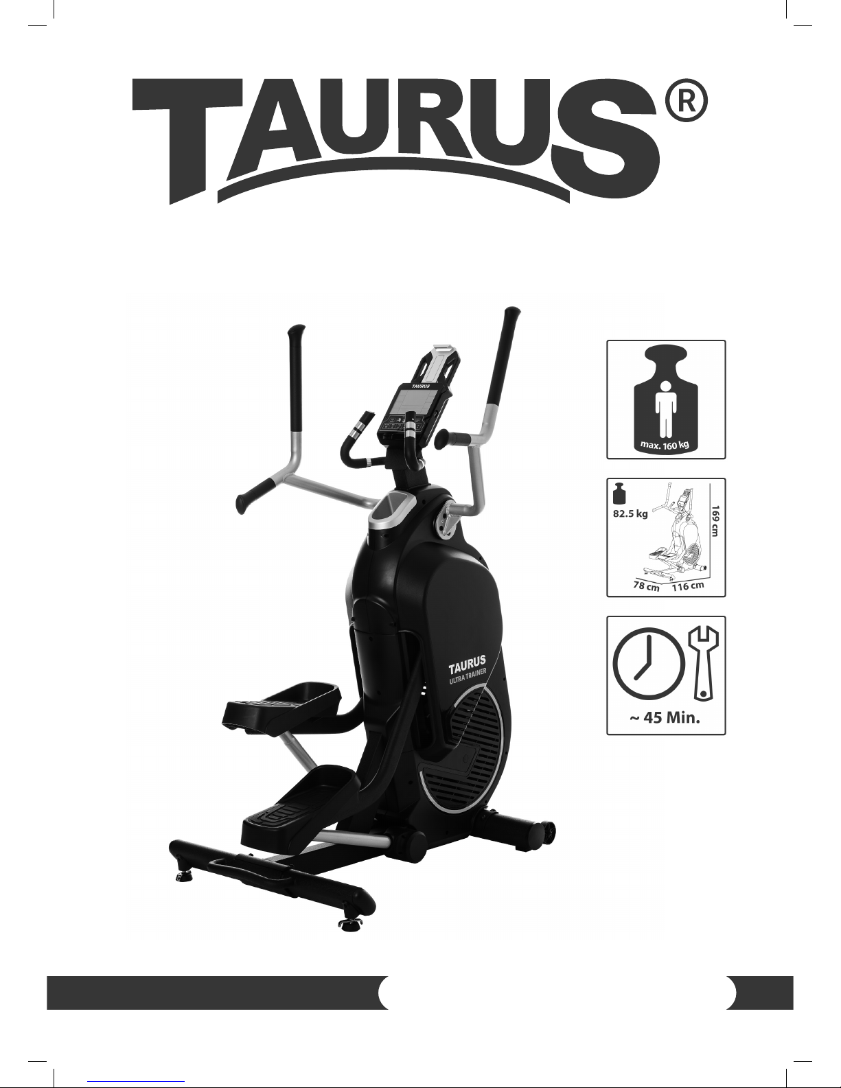
ELLIPTICAL ULTRA TRAINER
TF-UT
Page 2

ULTRA TRAINER
2
Page 3

3
Dear Customer,
Thank you for deciding for a high-quality training equipment of the brand Taurus®,
the brand that makes athlete‘s hearts beat faster. Taurus® oers a wide range of home
tness equipment like elliptical cross trainers, ergometers, treadmills and rowing
machines. Taurus® equipment is the optimal equipment for all those who want to
train at home independent of goals and tness level. For further information please
visit www.sport-tiedje.com or www.taurus-tness.com.
SAFETY NOTICE
Please read all of the instructions carefully before assembly and rst
use. These instructions are intended to ensure speedy assembly and
explain safe usage. Make sure that all people exercising with the
equipment (in particular children and persons with limited physical, sensory, mental or
motor capabilities) are informed about these instructions and its content in advance.
In case of doubt, a responsible person must supervise the use of the equipment.
This equipment has been manufactured according to the latest safety knowledge. As
far as possible, potential safety hazards which could cause injury have been eliminated.
Make sure to follow the instructions carefully and that all parts are securely in place. If
required, read through the instructions again to correct any mistakes.
Please pay close attention to the safety and maintenance instructions given here. The
contract partner cannot be held liable for damage to health, accidents or damage to
the equipment when it is not used in accordance with these instructions.
The equipment is suitable for home use and semi-professional use (e. g., hospitals,
clubs, hotels, schools, etc.).
Retain these instructions in a safe place for future reference, maintenance or when
ordering replacement parts.
Page 4

ULTRA TRAINER
4
CONTENT
1 GENERAL INFORMATION 6
1.1 Technical data 6
1.2 Personal safety 7
1.3 Set-up place 8
2 ASSEMBLY INSTRUCTIONS, MAINTENANCE AND CARE 8
2.1 General instructions 8
2.2 Errors and error diagnosis 9
2.3 Maintenance and service calendar 10
3 ASSEMBLY 11
3.1 Package contents 11
3.2 Assembly instructions 13
4 OPERATING INSTRUCTIONS 21
4.1 Console display 21
4.2 Button functions 22
4.3 Turning on and o the equipment 23
4.4 Programmes 25
4.4.1 Quick Start 25
4.4.2 Manual Modus 26
4.4.3 Valley / Hill Valley / High Land Rift Valley mode 27
4.4.4 Interval 10/20 / Interval 20/10 / Interval MAX 28
4.4.5 Heart Rate Control 30
4.4.6 Recovery 31
4.5 Check or delate saved data 31
5 WORKOUT INSTRUCTIONS 34
5.1 Heart rate measuring 34
5.2 10 tips for eective ergometer training 37
5.3 Designing a workout 38
5.4 Stretching exercises for leg & chest muscles 40
5.5 Workout journal 42
Page 5

5
6 WARRANTY INFORMATION 43
7 DISPOSAL 45
8 ORDERING ACCESSORIES 46
9 ORDERING SPARE PARTS 47
9.1 Service hotline 47
9.2 Serial number and model name 47
9.3 Parts list 48
9.4 Exploded drawing 50
Page 6

ULTRA TRAINER
6
1 GENERAL INFORMATION
1.1 Technical data
LCD display of
+ training distance
+ calories burnt in kcal
+ heart rate (when using the hand sensors or a chest strap)
+ watts
+ cadence (rotations per minute)
+ speed
+ training time in min
+ calorie burn rate per minute
Resistance system: Hybrid air and magnetic resistance system
Total number of training programs: 11
User dened programs: 3
Heart rate controlled programs: 4
Weight and dimensions::
Article weight (gross, including packaging): 85 kg
Article weight (net, without packaging): 82,5 kg
Set-up dimensions (L x W x H): approximately 1160 mm x 780 mm x 1690 mm
Maximum user weight: 160 kg / 352 lbs
Page 7

7
1.2 Personal safety
+ Before you start using the equipment, you should consult your physician that
this type of exercise is suitable for you from a health perspective. Particularly
aected are persons who: have a hereditary disposition to high blood pressure
or heart disease, are over the age of 45, smoke, have high cholesterol values, are
overweight and/or have not exercised regularly in the past year.
+ Please note that working out excessively can seriously damage your health. Please
also be aware that heart rate monitoring systems might be imprecise.
+ The equipment may only be used for its intended purpose; that means for lower
body training for adults.
+ Any other usage is prohibited and potentially dangerous. The contract partner
cannot be held liable for damage resulting from improper use.
+ The equipment is strictly for use by one person at a time.
+ Children should not be allowed unsupervised access to the equipment.
+ Before starting your training, make yourself familiar with all of the equipment‘s
functions and setting options. Have an expert explain the correct usage of the
product to you.
+ Make sure that nobody is in the range of motion of the equipment while exercising.
+ Keep your hands, feet and other body parts, hair, clothing, jewelry and other
objects well clear of moving parts.
+ During use, wear suitable sports clothing rather than loose or baggy clothing.
When selecting sports shoes, think about the suitability of the sole – preferably
this should be made of rubber or other non-slip materials. Shoes with heels,
leather soles, studs or spikes are not suitable. Never work out in bare feet.
+ It is also important to take note of the information given in the workout instructions
for creating a workout plan.
+ At the rst signs of weakness, nausea, dizziness, pain, diculty in breathing or
other abnormal symptoms, stop your workout immediately and, if necessary,
consult your physician.
+ Without prior agreement from your authorized contract partner, opening the
equipment is prohibited.
Page 8

ULTRA TRAINER
8
1.3 Set-up place
+ The equipment should only be used indoors, in a suciently heated and dry area
(ambient temperature between 10°C and 35°C). The equipment should not be
used outdoors or in rooms with high humidity (over 70%) like swimming pools. The
equipment should only be stored in surroundings with an ambient temperature
between 5°C and 45°C.
+ The training room should be well ventilated during training and not be exposed to
any draughts.
+ Choose a location in which to place the equipment such that there is enough free
space/clearance to the front, the rear and to the sides of the equipment (at least
1.50 m). Furthermore, the equipment should not be set up in main entrances or on
escape routes.
+ Always keep the power cable away from hot surfaces and grounds and make sure
that the cable is not stuck somewhere or becomes a „trip hazard“.
+ No objects of any type should be inserted into the openings of the equipment.
+ The equipment should be placed on a level and solid surface, any unevenness in
the oor should be leveled out.
+ A oor protective mat / equipment underlay can help to protect high-quality oor
coverings (parquet, laminate, cork, carpets) from dents and sweat and can help to
level out slight unevenness.
2 ASSEMBLY INSTRUCTIONS, MAINTENANCE AND CARE
2.1 General instructions
+ Please check if all parts and tools belonging to the equipment are included in the
delivery and if there is any transport damage. If there are any complaints, please
contact your contract partner directly.
+ Some of the nuts and bolts to be used in assembly are already pre-mounted in
order to make set-up as easy as possible.
+ The equipment must be assembled by adults. In case of doubt, ask for assistance
from another person with technical skills.
+ Keep children away from the equipment during assembly, because small parts are
included in the delivery and may be swallowed.
+ Make sure that you have enough space (at least 1.50 m) in every direction during
assembly.
Page 9

9
+ Do not leave any tools and packaging materials like plastic sheeting laying around
to avoid danger of suocation for children.
+ Assemble the equipment on an underlay mat or on the cardboard packaging in
order to avoid damage to the equipment and to the oor (scratches).
+ Before starting assembly, all individual parts should be placed on the oor next to
each other.
+ Read the assembly instructions carefully and assemble the equipment according
to the illustrations. Proceed carefully and cautiously.
+ First loosen all parts and check for their correct tting. Then tighten the screws
using a tool.
+ Modications to the design or improper repairs may pose a hazard to the user and
should not be carried out. The product warranty may be void as a result.
+ Only authorized service technicians are permitted to carry out all servicing and/or
repairs – it excludes maintenance and care.
+ Damaged or worn components may impair your safety and the lifespan of
the equipment. You should therefore immediately replace damaged or worn
components. Please contact your contract partner in such a case. The equipment
should no longer be used until it has been repaired. When needed, only use
original Taurus® spare parts.
+ Check the tightness of all screw connections once a month.
+ In order to be able to guarantee the constructively dened safety level of this
equipment, we recommend having the equipment regularly maintained (at least
once a year) by specialists (service technicians of your contract partner).
+ The equipment may be cleaned of dust, dirt and sweat using a damp cloth. The
use of solvents should be strictly avoided. Also, make sure that no liquids (e. g.
sweat) get into the openings of the equipment (e. g. console).
2.2 Faults and troubleshooting
The equipment runs through regular quality controls during production. Nevertheless,
errors or malfunctions on the equipment may occur. Individual parts are often the
cause of faults and replacement is usually sucient. Please use the following overview
to see the ve most common errors and how to repair them. If the equipment still
does not work properly, please contact your contract partner.
Page 10
ULTRA TRAINER
10
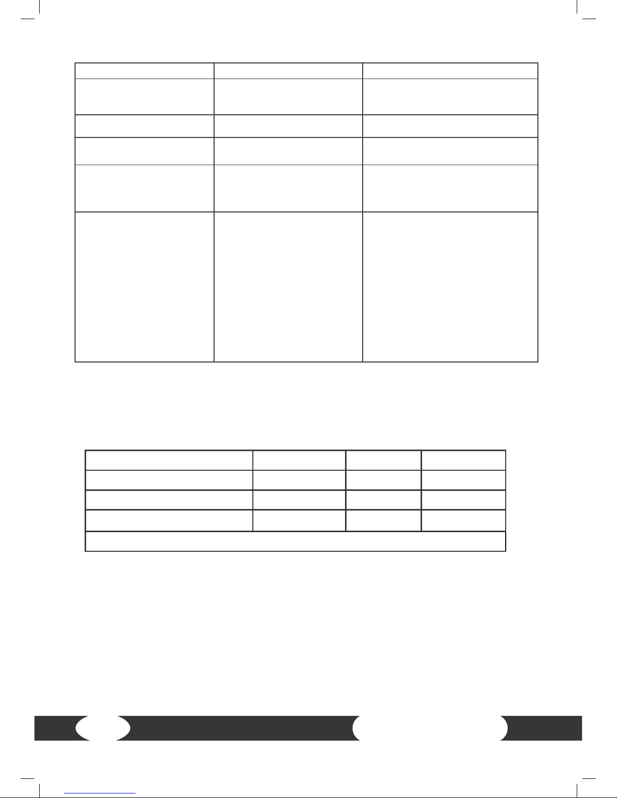
Problem Cause Solution
Crackling noise in pedal
area
Loose pedals Tighten the pedals
Equipment wobbles Equipment is not level Adjust the supporting feet
Handlebar/saddle wobbles
Screws are loose Tighten screws
Display does not turn on
Power is disconnected Check all plug connections and
see if the plug is plugged in
No pulse reading
• Sources of interference in
the room
• Using a chest strap:
- Unsuitable chest strap
- Chest strap is incorrectly
positioned
- Batteries are empty
• Eliminate sources of interference
(e. g. mobile phone, loudspeaker,
etc.)
• Use a suitable chest strap (see
recommended accessories)
• Reposition the chest strap and/
or moisten the electrodes
• Charge the batteries
2.3 Maintenance and service calendar
The following routine work must be done in the specied time intervals:
Part Weekly Monthly Twice a year
Display console C I
Tighten the pedals I
Plastic cover
C I
Legends: C = cleaning; I = inspect
Page 11
11
3 ASSEMBLY
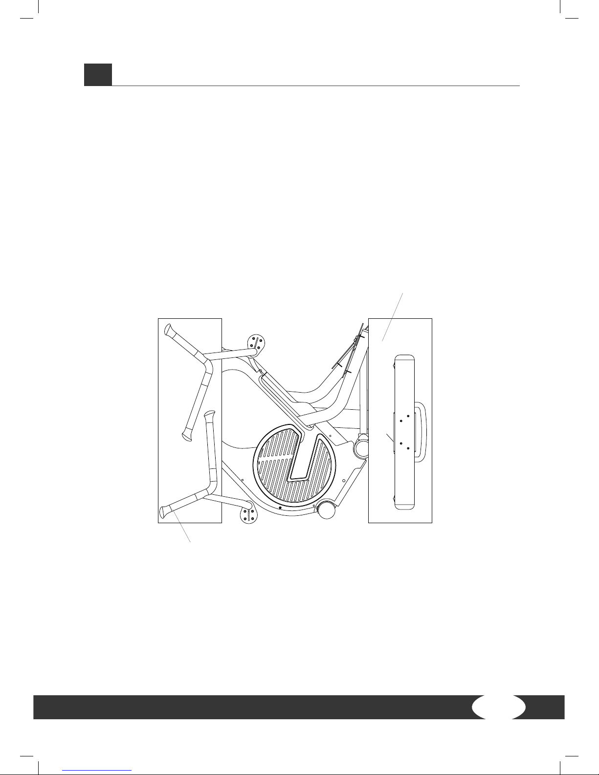
3.1 Package contents
Warning: Be careful while unpacking
Place the box at on the oor so that the upper cover can be removed. Remove the
parts (i. e., handles, pedal tubes, rear base, console, etc.) from the upper styrofoam 1
and 2. Remove the styrofoam completely.
POLYFOAM(1)
POLYFOAM(2)
Page 12

ULTRA TRAINER
12
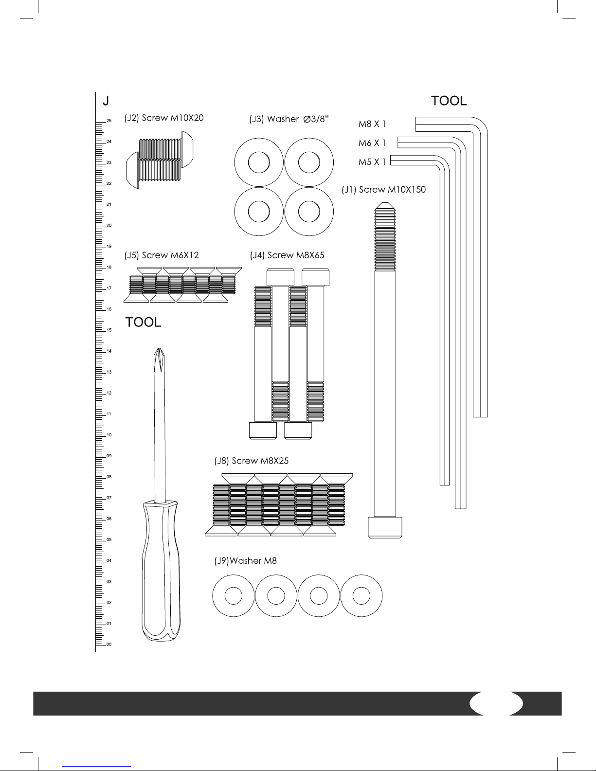
Parts list
Page 13
13
Parts list
Page 14

ULTRA TRAINER
14
3.2 Assembly instructions
Before starting assembly, look carefully through the individual assembly steps
shown and assemble the equipment in the order indicated.
Step 1: Be careful while unpacking
(1) Place the box at on the oor and remove the
upper box at rst.
(2) Lift the main frame and remove the styrofoam.
Place the main frame on an even oor.
Note: For safety reasons, removing the main frame
and the assembly itself should be done by at least
two persons.
A
Step 2: Preparation of the assembly
(1) Remove the four pre-mounted screws
(Z2) from the paper roll (Z1). Repeat this
step on the other side.
(2) Remove the pre-mounted screw (J2)
and the paper roll.
Note: The J2 screws are required for the
following assembly. However, the parts
Z1 and Z2 are no longer required.
A
A
Z2
PAPER TUBE
Z1
J2
Page 15
15
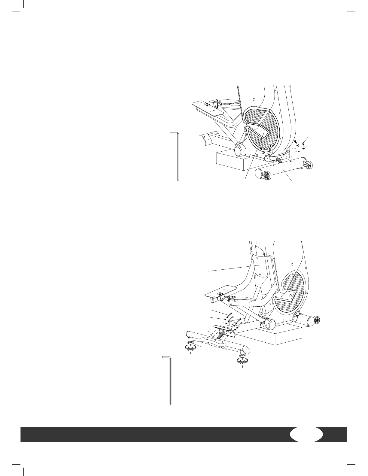
Step 3: Assembly of the front base
(1) Mount the front base (B) with the screw (J2) and the washer (J3) on the bracket of
the main frame (A).
Note: The J2 screws were removed according to gure 2.
Step 4: Assembly of the rear base
(1) Mount the rear base (C) with the
screw (J4) and the washer (J9) on the
bracket of the main frame (A).
(2) After the assembly, you can place the
machine completely on the oor.
Note: Align the levelling feet (C5) at the
bottom of the rear base so that the machine stands even and stable.
BA
J2
J3
6 m/m
BA
J2
J3
6 m/m
J4
A
J9
C
C5
6 m/m
6 m/m
Page 16

ULTRA TRAINER
16
Step 5: Assembly of the console upright post
(1) Connect the console cables (D1 and
A1).
(2) Slide the console upright post (D) on
the main frame (A).
(3) Tighten the screw (J1), see illustration
A.
Note: Please make sure that the cables
are correctly connected and that the cables are not clamped during the assembly.
Step 6: Assembly of the console
(1) Remove four screws (G1) at the back
of the console (G).
(2) Connect the console cables (D1, G3,
G4) and the pulse cable (D4) with the
console. The pulse cables can be exchanged.
Note: Please make sure that the cables
are correctly connected. Push excess
cable in the console upright post (D).
Please make sure that the cables are not
clamped during the assembly of the console.
(3) At rst, tighten the four screws (G1)
manually and then with a screwdriver to
tighten the console (G) safely on the console upright post (D).
8 m/m
A
A1
D
J1
J1
D1
View A
8 m/m
G
G1
D4
D1
G3
G4
D
8 m/m
5 m/m
E1
E2
J8
E2
A
J8
J8
R
R
J5
H1
A
Abb. A
Page 17

17
Step 7: Assembly of the handles
(1) Mount the right handle (E2) with the screw (J8) on the shaft of the main frame (A).
(2) Mount the left handle (E1) with the screw (J8) on the shaft of the main frame (A).
Note: Please pay attention to the markings (R and L) on the connecting tube of the
handles and on the shaft in order to mount the handles correctly.
Step 8.1: Assembly of the treads
The left and right treads can be exchanged.
(1) Mount the tread (H1) with the screw (J5) on
the tread plate. Tighten the screw. Repeat this
step on the other side.
5 m/m
E1
E2
J8
E2
A
J8
J8
R
R
5 m/m
E2
J8
E2
J8
R
R
J5
H1
A
5 m/m
E1
E2
J8
E2
A
J8
J8
R
R
J5
H1
A
Page 18

ULTRA TRAINER
18
Step 8.2: Assembly of the upholstery
The left and the right upholsteries can be exchanged. The front and rear sides can be
exchanged as well.
(1) Insert the upholstery (H2) in the front clip of the tread (H1), see illustration A.
(2) Insert the upholstery in the rear clip of the tread (H2), see illustration B.
(3) Press the upholstery at against it.
Page 19

19
Step 9: Use the keys for setting the resistance
When the console is turned on, press the keys on the little handles to set the resistance. Press +LOAD on the right side to increase the resistance. Press -LOAD on the left
side to reduce it.
Step 10: Transport the equipment
When you want to move the equipment to another place, just tilt it on both connecting tubes (big handles) until the transport wheels touch the oor. Move the machine
to the preferred place. Lower the machine carefully. If required, align the levelling
feet once again to ensure the stability of the machine itself.
WARNING: Never tilt the machine on your own but always with at least two persons.
Do not tilt the machine when you suer from physical disorders.
Page 20

ULTRA TRAINER
20
Step 11: Assembly of the cable
Plug the power plug in the connection jack on the main frame of the machine, before
you connect the power cable to the socket.
Step 12: Additional features
(1) It is recommended to pedal backwards, because it is more comfortable and oers
a more intensive training.
(2) Adjustable holder for smartphone/tablet
(3) USB Port beside the console as charging station
(4) Cup holder
I
I
Page 21

21
4 OPERATING INSTRUCTIONS
4.1 Console display
UP
BUTTON FUNCTIONS
7$*+($575$7(
TIME
The time counts from 00:00 to a maximum of 99:59 in
1-minute increments.
SPEED
Displays the current speed.
The maximum speed is 99.9 km/h or mph.
RPM
Displays the rotations per minute.
Range from 0 to 999 RPM.
DISTANCE
Counts the total distance from 0.0 to 999.9 km or miles in
increments of 0.1kilometres or miles.
CALORIES
Counts the calories consumption from 0 to a maximum of
9999 calories during the training. The unit for reducing or
increasing is 10 kcal. (This values serve as rough guides for
comparing with dierent training sessions. However, they
cannot be used for medical treatment.)
WAT T
Displays the current training wattage.
Range from 0 to 999.
PULSE Set a target pulse from 0 – 30 to 230.
Page 22

ULTRA TRAINER
22
4.2 Button functions
START/STOP
Start or stop the training. Press it in the Standby mode to
start Quick Start in the MANUAL programme.
DOWN Reduce the functional values or the training resistance
UP Increase the functional values or the training resistance
ENTER Conrm the settings
RESET
Reset the current setting, the screen returns to the initial
training mode in the selection. Hold it pressed for two
seconds in the Standby mode to reset all.
RECOVERY Activate the recovery function.
RECORDED DATA Press in the Stop mode to check the data.
SAVE/DELETE
SAVE: Press STOP to stop the training. The display asks
whether you want to save the data. Press SAVE.
DELETE: When you check the saved data, press DELETE. The
system asks whether you really want to delete the data.
Conrm with ENTER.
INTERVAL
20/10 20 seconds training, 10 seconds recovery,
8 repetitions
10/20 10 seconds training, 20 seconds recovery,
8 repetitions
MAX 20 seconds training at the intensity 5, 80 seconds
recovery at the intensity 1, 8 repetitions
Page 23

23
4.3 Turn on the machine
(1) Connect the monitor to the power and press RESET for two seconds. The LCD
screen displays all segments for two seconds and a signal sounds (see g. 1).
Go to the settings of calendar and time (g. 2 to 5). Set the time and the calendar with
the UP/DOWN buttons. Conrm with ENTER.
FIGURE 1
FIGURE 5
YEAR SELECT PRESS ENTERMONTH SELECT PRESS ENTER
DAY SELECT PRESS ENTER
PRESS ENTER
HOUR SELECT PRESS ENTER
MINUTE SELECT
FIGURE 2 FIGURE 4
FIGURE 3
Page 24

ULTRA TRAINER
24
(2) Press the UP/DOWN buttons to choose the user (U) from 1 to 4. Conrm with
ENTER (g. 6). Enter the user data for gender, age, height, and weight (g. 7 to 10).
FIURE 6
FIURE 9 FIURE 10
FIURE 7 FIURE 8
USER SELECT PRESS ENTER
SEX SELECT PRESS ENTER
AGE SELECT PRESS ENTER
HEIGHT SELECT PRESS ENTER
WEIGHT SELECT PRESS ENTER
Page 25

25
4.4 Programmes
The programmes can be chosen as follows: MANUAL q VALLEY q HILL VALLEY q
HIGH LAND RIFT VALLEY q INTERVAL 10/20 q INTERVAL 20/10 q INTERVAL MAX q
H.R.C. (g. 11 to 18).
4.4.1 QUICK START in the manual programme
(1) Press ENTER in the MANUAL programme (g. 19).
(2) Press START/STOP to start the training (g. 20). The resistance can be adjusted
during the training.
(3) Press START/STOP to stop the training.
FIURE 11 FIURE 12 FIURE 13
FIURE 14 FIURE 15
FIURE 17 FIURE 18
FIURE 16
FIURE 11 FIURE 12 FIURE 13
FIURE 14 FIURE 15
FIURE 17 FIURE 18
FIURE 19 FIURE 20
FIURE 16
Page 26

ULTRA TRAINER
26
4.4.2 Manual Mode
(1) Choose the MANUAL mode and conrm with ENTER (g. 19). Increase or reduce
the intensity level (from 1 to 6) with the UP/DOWN buttons. Conrm with ENTER.
(2) Target values for TIME/DISTANCE/CALORIES/PULSE can be pre-set. Press START/
STOP to start the training (g. 20). Press RESET to return to the setting in the MANUAL
mode.
(3) The resistance can be adjusted during the training.
Press ENTER to continue the previous setting
Press START to get started, do not set up any target value.
MANUAL SELECT
TAG TIME SELECT
LOAD SELECT
TAG DISTANCE SELECT
TAG CALORIES SELECT
TAG HEART RATE SELECT
PRESS ENTER
PRESS ENTER
PRESS ENTER
PRESS ENTER
PRESS ENTER
PRESS START
PRESS START
Page 27

27
4.4.3 VALLEY / HILL VALLEY / HIGH LAND RIFT VALLEY mode
(1) Choose the VALLEY / HILL VALLEY / HIGH LAND RIFT VALLEY programme (g. 21
to 23). Conrm with ENTER.
(2) The time can be pre-set. Press START/STOP to start the training (g. 24).
(3) After the training start, the time is counted down. When the time reaches zero,
the screen lights up and a signal sounds. Press any button to stop the signal.
FIURE 21
FIURE 24
FIURE 22 FIURE 23
Press ENTER to continue the previous setting
Press START to get started, do not set up any target value.
HILL VALLEY SELECT
TAG DISTANCE SELECT TAG CALORIES SELECT
TAG HEART RATE SELECT
PRESS ENTER
PRESS ENTER
PRESS ENTER
PRESS ENTER
PRESS ENTER
TAG TIME SELECT
PRESS START
PRESS START
VALLEY SELECT
HIGHT LAND RIFT VALLEY SELECT
Page 28

ULTRA TRAINER
28
4.4.4 INTERVAL 10/20 / INTERVAL 20/10 / INTERVAL MAX
(1) Choose the INTERVAL 10/20 / INTERVAL 20/10 / INTERVAL MAX programme with
the UP/DOWN buttons (g. 25 to 27). Conrm with ENTER.
INTERVAL 10/20
(training 10 seconds, recovery 20 seconds)
1. Press START in the 10/20 mode. The training starts after three seconds.
2. WORK TIME counts 10 seconds down. The training values for distance, calories,
watt, speed, and RPM are displayed. 1/8 WORK 0:10 is displayed. The countdown
starts (g. 28).
3. In the last three seconds, a signal sounds as reminder. Then the WORK mode turns
in the REST mode.
4. REST TIME counts 20 seconds down. 1/8 REST 0:20 is displayed (g. 29). The countdown starts.
5. In the last three seconds, a signal sounds as reminder. Then the REST mode turns
in the WORK mode.
6. The steps 2 to 5 are repeated. Each repetition counts until REST 08/8 is displayed.
Then the programme stops and then displays the training values (g. 30).
INTERVAL 20/10
(training 20 seconds, recovery 10 seconds)
1. Press START in the 20/10 mode. The training starts after three seconds.
2. WORK TIME counts 20 seconds down. The training values for distance, calories, watt,
speed, and RPM are displayed. 1/8 WORK 0:20 is displayed. The countdown starts.
3. In the last three seconds, a signal sounds as reminder. Then the WORK mode turns
in the REST mode.
4. REST TIME counts 10 seconds down. 1/8 REST 0:10 is displayed (g. 29) The countdown starts.
5. In the last three seconds, a signal sounds as reminder. Then the REST mode turns
in the WORK mode.
6. The steps 2 to 5 are repeated. Each repetition counts until REST 08/8 is displayed.
Then the programme stops and then displays the training values.
Page 29

29
INTERVAL MAX
(training 20 seconds at the intensity 5, recovery 1:20 seconds at intensity 1)
1. Press START in the MAX mode. The training starts after three seconds.
2. WORK TIME counts 20 seconds down and the intensity increases to 5. The training
values for distance, calories, watt, speed, and RPM are displayed. 1/8 WORK 0:20 is
displayed. The countdown is started.
3. In the last three seconds, a signal sounds as reminder. Then the WORK mode turns
in the REST mode.
4. REST TIME counts 1:20 seconds down and the intensity is reduced to 1. 1/8 REST
1:20 is displayed. The countdown starts.
5. In the last three seconds, a signal sounds as reminder. Then the REST mode turns
in the WORK mode.
6. The steps 2 to 5 are repeated. Each repetition counts until REST 08/8 is displayed.
Then the programme stops and then displays the training values.
PRESS INTERVAL 10/20 QUICK KEY
PRESS INTERVAL 20/10 QUICK KEY
PRESS INTERVAL MAX QUICK KEY
INTERVAL 10/20 SELECT
PRESS START
OR
INTERVAL 20/10 SELECT
PRESS START
OR
INTERVAL MAX SELECT
PRESS START
OR
FIURE 25 FIURE 26 FIURE 27
FIURE 28 FIURE 29 FIURE 30
Page 30

ULTRA TRAINER
30
4.4.5 Heart rate control
(1) In the H.R.C. mode (g. 31), the screen displays 55%, 75%, 90%, and TARGET (g.
32 to 35). Choose the preferred heart rate with the UP/DOWN buttons.
(2) The time can be pre-set. Press START/STOP to start the training.
(3) After the training start, the time is counted down. When it reaches zero, the screen
lights up and a signal sounds. Press any button to stop the signal. When there is no
pulse for six seconds, the LCD screen displays PULSE INPUT as reminder until a pulse
is set (g. 36).
FIURE 31 FIURE 32 FIURE 33
FIURE 34 FIURE 35 FIURE 36
PULSE SETTING
Press START to get started, do not set up any target value.
TAG TIME SELECT
PRESS START
PRESS START
H.R.C. SELECT PRESS ENTE
RP
RESS ENTER
PRESS ENTER TO TAG SELECT
55% 75% 90% TAG SELECT
Page 31

31
4.4.6 Recovery
Press RECOVERY after the pure training time and grasp both handles. All function
displays stop except for TIME. It counts down from 00:60 to 00:00 (g. 37). When the
console detects a pulse signal, the LCD screen displays RECOVERY SCANNING. When
the console does not detect a pulse signal, the LCD screen reminds of it by displaying
PULSE INPUT! The screen displays your recovery pulse status with F1 to F6 (g. 38). F1
stands for the best value, F6 for the worst. Continue training to improve your recovery pulse. Press RECOVERY again to return to the main display.
4.5 Check or delete saved data
1. When the machine is turned on, the calendar and the user data U1 to U4 (g. 39 to
47) have to be entered. Please make sure that the calendar data are correctly entered.
2. Press START/STOP during the training to stop the display and press SAVE.DELETE. SAVE FINISH is displayed (g. 48). The training values are saved now. The console
saves all training values, storages, time, average speed, average RPM, average Watt
value, distance, and calories.
FIURE 37 FIURE 38
FIURE 37 FIURE 38
FIURE 39 FIURE 40 FIURE 41
FIURE 42 FIURE 43 FIURE 44
Page 32

ULTRA TRAINER
32
3. When you want to check the data, press the mode selection in the main programme and press RECORDED DATA. Then press UP/DOWN to see the previously saved
data (g. 49).
4. Check in RECORDED DATA and press SAVE.DELETE. Conrm the deletion of the saving with ENTER (g. 50).
5. Delete all data: Press SAVE.DELETE for six seconds in the calendar setting or in the
RECORDED DATA control. DELETE ALL! is displayed (g. 51). Conrm with ENTER. All
data are deleted (g. 52). The computer reboots after 15 seconds and returns to the
calendar default 20170101.
FIURE 45
FIURE 48
FIURE 46 FIURE 47
PRESS SAVE.DELETE KEY
PRESS STOP
Stpe 1. Remove the four screws (G1) from the back of
FIURE 45
FIURE 48
FIURE 46 FIURE 47
FIURE 49
FIURE 51
FIURE 52
FIURE 50
PRESS SAVE.DELETE KEY
PRESS STOP
Page 33

33
Note:
1.When you stop treading for more than four minutes, the computer turns to the
energy save mode. All settings and training values remain saved until you start the
training again.
2. When the computer does not work, please plug out the adapter and plug it in
again.
PRESS ENTER
DATA SELECT PRESS RESET
PRESS RECORDED DATA KEY
PRESS SAVE.DELETE KEY
PRESS ENTER
PRESS SAVE.DELETE KEY 6 SECONDS
Delete single data
Delete all data and reset
Set up the Date
Page 34

ULTRA TRAINER
34
5 WORKOUT INSTRUCTIONS
5.1 Heart rate measuring
Pulse measuring through hand sensors
The hand sensors integrated in the handles allow you to determine your heart rate.
You can measure your heart rate by lightly grasping the sensors with both hands at the
same time. Blood pressure changes occur due to the heartbeat. The sensors measure
the changes to the electric skin resistance caused by it. These values are then used to
create an average and are displayed on the screen of the console as a heart rate.
Note:
For some people, the skin resistance change caused by the heart rate is so minimal
that the measurements do not allow for usable values. Strong callus or sweat on the
hands may also impair a correct measurement. In such cases, the heart rate will not be
shown at all or only incorrectly.
If the measurement is incorrect or not taken at all, please check if it happens to only
one person or to several people. If the pulse display only does not work in a single
case, the equipment is not defective. In this case, we recommend using a chest strap
to achieve a permanently correct heart rate display.
CAUTION: Your training equipment is not a medical device. Dierent factors
may inuence the accuracy of the heart rate display. The heart rate display only
serves as a training aid.
Telemetric heart rate measuring
This ergometer is already equipped with a heart rate receiver as standard. Using a
chest strap makes it possible for you to have a wireless heart rate measuring. This
optimal and ECG-precise type of measuring reads the heart rate directly from the
skin through a transmitting chest strap. The chest strap then sends the impulse to the
receiver integrated in the console.
Positioning the chest strap and moistening the electrodes:
Place the belt directly below the chest, while the transmitter should be placed on the
middle of the chest. The chest strap should sit comfortably, but not too loose. If the
belt is too loose, the contact to the electrodes may be disrupted or the belt may slip
while exercising. The transmitter turns on automatically once it is put on. In order to
allow for a precise measuring, you should moisten the rubber electrodes. This is best
done with a special chest strap contact gel, which is also used for ultrasound scans.
Page 35

35
Note:
If you have not been active in doing sports for a longer period of time, you should
rst go to your physician in order to discuss your training with them. You should also
contact your physician in advance in the event of heart problems, high/low blood
pressure and obesity.
Training with heart rate orientation
Heart rate orientation guarantees an extremely eective and healthy training. Through
your age and the following table, you can quickly and easily read and determine the
optimal pulse for your training. An alarm will sound if your heart rate exceeds the set
target heart rate. Which target heart rate is important for which training goal can be
found out in the following.
Fat burning (weight management): The main goal here is to burn deposits of fat. In
order to achieve this training goal, a low training intensity (approximately 55% of the
maximum heart rate) and a longer training period are required.
Cardiovascular training (cardio training): The primary goal is to increase stamina
and tness through an improved provision of oxygen through the cardiovascular
system. In order to achieve this training goal, medium intensity (approximately 75%
of the maximum heart rate) with a medium training period is required.
Anaerobic (maximum) load training: The main goal of maximum load training is to
improve recovery after short, intense loads in order to be able to quickly return to the
aerobic zone. In order to achieve this training goal, a high intensity (approximately
90% of the maximum heart rate) with short, intense load is required, which is followed
by a recovery phase in order to prevent muscle fatigue.
Page 36

ULTRA TRAINER
36
Example:
For a 45-year-old man or woman, the maximum heart rate is 175 (220 - 45 = 175).
• The fat burning target zone (55%) is at approximately 96 beats/min.
= (220 - age) x 0.55.
• The cardio target zone (75%) is at approximately 131 beats/min.
= (220 - age) x 0.75.
• The maximum heart rate for an anaerobic load training (90%) is at approximately
157 beats/min. = (220 - age) x 0.9.
20
80
100
120
140
160
180
200
220
65 7060555045403525 30
200
195
190
185
180
175
170
180
150
110
146
107
175
171
166
162
157
153
148
143
139
135
131
128
124
105
102
99
96
94
91
88
85
83
113
116
120
144
139
136
150
155
160
165
Heart rate diagram for training intensity
Maximum pulse (220-age)
90% of maximum pulse - anaerobic (maximum) intensity training
75% of maximum pulse - cardiovascular training (cardio training)
55% of maximum pulse - fat burning (weight control)
Heartbeats
Age
Page 37

37
5.2 10 tips for eective ergometer training
1. Set goals
What would you like to achieve with your training? Weight regulation, improved
stamina, prevent risk of disease, more mobility, cardiovascular training, etc. In order
to achieve your long-term training goal, set individual partial goals, e. g., weekly or
monthly goals.
2. Concentration on training
Try to only dedicate yourself to your training session and do not be distracted.
3. Position yourself correctly while exercising
As you pedal, your upper body should be shifted slightly forward and your back held
straight. Avoid side-to-side motion in the hips and back.
4. Correct breathing / appropriate resistance level
Do not overexert yourself physically and mentally by starting with resistance levels
that are too high. Start slowly and increase the resistance steadily. Aim for regular and
calm breathing.
5. Keep yourself properly hydrated
Drink, drink, drink! Have a drinking bottle close by during your workout.
6. Sucient recovery periods
Allow your body and your muscles enough time to recover after your workout. Only a
relaxed muscle will be fully operational again.
7. Choose a diversied program
Switch your focus between dierent muscle groups and dierent levels of intensity
during your workout.
8. Creating the right workout
Every training session should have a warm-up phase, a cool-down phase and a
targeted stretching. It increases physical and mental performance and prevents
injuries and sore muscles.
Page 38

ULTRA TRAINER
38
9. Workout journal
Keep a record of your training sessions. Note the date, resting pulse, active pulse,
recovery pulse, resistance level, time, distance, calories burnt and tness level.
10. Reward yourself
Do something good for you and your body after training or after achieving a partial
goal. Go to the sauna or a swimming pool. Mix a protein shake or enjoy a delicious
salad.
5.3 Designing a workout
We recommend two or three workouts per week. Warm up for about ve minutes
before starting each workout. Finish the workout with a cool-down and targeted
stretching.
Warm-up approx. ve min. Dynamic movement of large muscle groups at a
low intensity. Core body temperature increases
and the metabolic process is speeded up.
WEEK 1 + 2
Beginner Advanced
Days Duration Intensity Duration Intensity
Mon 20 min. Slow speed 30 min. Moderate speed
Wed 20 min. Slow speed 30 min. Moderate speed
Fri 20 min. Slow speed 30 min. Moderate speed
WEEK 3 + 4
Beginner Advanced
Days Duration Intensity Duration Intensity
Mon 25 min. Slow speed 35 min. Vary speed
Wed 25 min. Slow speed 35 min. Vary speed
Fri 25 min. Slow speed 35 min. Vary speed,
Page 39

39
WEEK 5 + 6
Beginner Advanced
Days Duration Intensity Duration Intensity
Mon 30 min. Moderate speed 40 min. Vary speed
Wed 30 min. Moderate speed 40 min. Vary speed
Fri 30 min. Moderate speed 40 min. Vary speed
WEEK 7 + 8
Beginner Advanced
Days Duration Intensity Duration Intensity
Mon 35 min. Vary speed 45 min. Vary speed
Wed 35 min. Vary speed 45 min. Vary speed
Fri 35 min. Vary speed, 45 min. Vary speed,
Cool-down approximately 5 min. Finish your training at low resistance and
at slow speed. Allow your body to gently
slow back down.
Page 40

ULTRA TRAINER
40
5.4 Stretching exercises for leg & chest muscles
1. Exercise: Stretching of front thigh / leg extension (quadriceps)
• Stable position, grab arches of feet
• Pull heel towards buttocks, knee points downwards
(no abduction)
• Straight upper body, avoid tilting the pelvic forward
(hollow back) by tensing the abdominal muscles
• Change legs
2. Exercise: Stretching the back thigh / leg curl (hamstring)
• Pull thigh towards upper body with both
hands
• Stretch through increased stretching in
the knee joint
• The lower leg maintains contact with the
oor, keep hips bent
• Change legs
Trapezius
Biceps
Pectoralis major
Straight abdominal
muscle
M. Extensor
digitorum
Gastrocnemius
Tibialis anterior
muscle
Quadriceps
Ileopsoas
Obliquus externus
Dentatus anterior
Deltoid muscle
Sternocleidomastoideus
Trapezius
Elevator scapolae
Rhomboid
muscle
Major back
muscle
Anconaeus
Gluteus
maximus
Adductor
Gastrocnemius
Soleus
Musculus
semimembranosus
Thigh biceps
Extensor
digitorum
Arm-radius muscle
Triceps
Deltoid muscle
Splenius capitis
Sartorius muscle
M. Teres major
Page 41

41
3. Exercise: Stretching the calf muscles (gastrocnemius)
• Place feet parallel to each other pointing forward,
the heels touch the oor
• Support yourself on a chair coming from a lunge
• Move your body weight to the front leg, press
your heel from the rear leg towards the oor and
hold the contact
• Slowly stretch your knee of the rear leg until you
feel the stretch in your calves
• Change legs
4. Exercise: Stretching the chest muscles (pectoralis major)
• Stand parallel to a wall
• Place your forearm at 90° to the wall with the elbow
just above shoulder height
• Turn your head and upper body gradually to the
opposite sides until you feel a stretch in the front
chest, of the shoulder being leaned on
• Pay attention to tension in your abdominal and
gluteal muscles
• Your weight is on your front leg
• Change legs
All recommendations of these instructions apply solely to healthy persons and
are not suitable for those with heart or cardiovascular problems. All of the tips
are intended only as a guide to help you create a workout. Your physician can
oer appropriate advice for particular, personal requirements.
We hope you enjoy your workout and have a lot of success!
Page 42

ULTRA TRAINER
42
5.5 Workout journal
Date
Training weight
Time (min.)
Calories burnt Body weight
Distance
Ø Pulse
Resistance level
I feel ...
(Copy template)
Page 43

43
6 WARRANTY INFORMATION
Taurus® training tness equipment is subject to strict quality controls. However, if a
tness equipment purchased from us does not work perfectly, we take it very seriously
and ask you to contact our customer service as indicated. We are happy to help you by
phone via our service hotline.
Error descriptions
Your tness equipment is developed for long-term, high-quality training. However,
should a problem arise, please rst read the operating instructions. For further
assistance, please contact your contract partner or call our service hotline. To ensure
your problem is solved as quickly as possible, please describe the defect as exactly as
possible.
In addition to the statutory warranty, we provide a warranty for every tness
equipment purchased from us according to the following provisions.
Your statutory rights are not aected.
Warrantee
The warrantee is the rst/original buyer and/or any person who received a newly
purchased product as a gift from the original buyer.
Warranty periods
The following warranty periods begin on delivery of the tness equipment.
Model Use Full warranty Frame
Ultra Trainer
Home use 24 months 30 years
Semi-professional use 12 months
Repair costs
According to our choice, there will either be a repair, a replacement of individual
damaged parts or a complete replacement. Spare parts, that have to be mounted
while assembling the equipment, have to be replaced by the warrantee personally
and are not a part of repair. After the expiration of the warranty period for repair costs,
a pure parts warranty applies, which does not include the repair, installation and
delivery costs.
Page 44

ULTRA TRAINER
44
The terms of use are dened as follows:
• Home use: solely for private use in private households up to 3 hours per day
• Semi-professional use: up to 6 hours per day (e. g. rehabilitation centers, hotels,
clubs, company gyms)
• Professional use: more than 6 hours per day (e. g. commercial gyms)
Warranty service
Within the warranty period, equipment which develops faults as a result of material
or manufacturing defects, will be repaired or replaced at our discretion. Ownership
of equipment or parts of equipment which have been replaced is transferred to us.
The warranty period is not extended nor does a new warranty period begin following
repair or replacement under the warranty.
Warranty conditions
For the warranty to be valid, the following steps must be taken:
Please contact our customer service by email or phone. If the product under warranty
has to be sent in for repair, the seller bears costs. After expiry of the warranty, the buyer
bears the costs of transport and insurance. If the fault is covered by our warranty, you
will receive a new or repaired equipment in return.
Warranty claims are invalid in case of damage resulting from:
• misuse or improper handling
• environmental inuences (moisture, heat, electrical surge, dust, etc.)
• failure to follow the current safety measures for the equipment
• failure to follow the operating instructions
• use of force (e. g. hitting, kicking, falling)
• interventions which were not carried out by one of our authorized service centers
• unauthorized repair attempts
Proof of purchase and serial number
Please make sure that you are able to provide the appropriate receipt when claiming
on your warranty. So that we can clearly identify the model of your equipment, and
for the purposes of our quality control, you will need to give the serial number of
your equipment, when contacting the service team. Where possible please have your
serial number and your customer number ready when you call our service hotline. It
will help us to deal with your request swiftly.
Page 45

45
If you have trouble nding the serial number on your tness equipment, our service
team is at your disposal to oer further information.
Service outside the warranty period
We are also happy to issue an individual cost estimate if there is a problem with your
tness equipment after the warranty has expired, or in cases which do not fall under
the terms of the warranty, e. g. normal wear and tear. Please contact our customer
service team to nd a quick and cost-eective solution to your problem. In such a case
you will be responsible for the delivery costs.
Communication
Many problems can be solved just by speaking to us as your contract partner. We
know how important it is to you as a user of the tness equipment to have problems
solved quickly and simply, so you can enjoy working out with minimal interruption.
For that reason, we also want to resolve your queries quickly and in a straightforward
manner. Thus, please always keep your customer number and the serial number of
the faulty equipment handy.
7 DISPOSAL
At the end of its operational life, this equipment cannot be disposed
of in normal household waste. Instead, it must be disposed of via an
electricals recycling centre. Further information can be obtained from
your local authority‘s recycling service.
The materials can be recycled as per their symbols. Through the reuse, recycling of
materials or other forms of recovery of old equipment, you make an important contribution to the protection of the environment.
Note for battery disposal
Do not dispose of used batteries in the household waste. Being the end-user, you are
obliged to dispose of used batteries at a commercial or municipal collection point.
You can also give the batteries, which you received from us, to one of our stores or
send these to our warehouse postage free (see contact details at the end of these
instructions).
Pb = Battery contains more than 0.004 percent by weight of lead.
Cd = Battery contains more than 0.002 percent by weight of cadmium.
Hg = Battery contains more than 0.0005 percent by weight of mercury.
Page 46

ULTRA TRAINER
46
8 ORDERING ACCESSORIES
SSport-Tiedje oor mat size XL
Art. No. ST-FM-XL
Chest strap contact gel 250ml
Art. No. BK-250
Fitness equipment care set
Art. No. HF-500
Polar Transmitter Chest Strap T34
uncoded
Art. No. T34
Page 47

47
9 ORDERING SPARE PARTS
9.1 Service hotline
So that we can give you the best possible service, please have your model name, part
number, serial number, exploded drawing and parts list ready.
SERVICE-HOTLINE
9.2 Serial number and model name
Before assembling your equipment, nd the serial number on the white sticker and enter
it in the appropriate space.
Serial number:
Brand / category: Model name:
Taurus elliptical cross trainer Ultra Trainer
+31 172 619961
info@tshop.nl
Ma. - Do. 9:00 - 17:00
Vr. 9:00 - 21:00
Za. 10:00 - 17:00
+33 (0) 172 770033
+49 4621 4210-933
service-france@sport-tiedje.fr
Lun. - Ven. 8:00 - 18:00
Sam. 9:00 - 18:00
80 90 16 50
+49 4621 4210-945
info@t-tness.dk
Ma. - Fr. 8:00 - 18:00
Lø. 9:00 - 18:00
+44 141 876 3972
orders@powerhousetness.co.uk
Mon. - Fri. 9:00 - 17:00
+49 4621 4210-0
service-int@sport-tiedje.de
Mon - Fri 8:00 - 18:00
Sat 9:00 - 18:00
+49 4621 4210-0
+49 4621 4210-699
service@sport-tiedje.de
Mo. - Fr. 8:00 - 18:00
Sa. 9:00 - 18:00
DE
NL
DK
UK
FR
INT
Page 48

ULTRA TRAINER
48
9.3 Parts list
No. Description Qty. No. Description Qty.
A MAIN FRAME 1 A47 NUT M5 3
A1 SENSOR WIRE 1600MM 1 A48 MAGNETIC 6
A2 TENSION CABLE 1 A49 MAGNETIC HOUSING 1
A3 SCREW M10X150MM 1 A50 SCREW M5X8MM 2
A4 BEARING 6005ZZ 4 A51 NUT 1
A5 BEARING NUT 1 A52 SCREW M5X10MM 1
A6 AXLE 1 A53 SCREW 8
A7 CLIP S25 1 A54 SCREW 8
A8 CRANK-L 1 A55 SMALL CHAIN COVER 1
A9 CRANK-R 1 A56 BOTTLE HOLDER 1
A10 SCREW M8X40MM 2 A58 MAIN CHAIN COVER (L) 1
A11 FIXING PIN 1 A59 MAIN CHAIN COVER (R) 1
A12 SCREW M8X20MM 1 A60 PEDAL TUBE (L) 1
A13 MOTOR 1 A61 PEDAL TUBE (R) 1
A14 SCREW M4X12MM 4 A62 SCREW M8X12MM 8
A15 SENSOR WIRE HOUSING 1 A63 END CAP 2
A16 SENSOR WIRE 1 A64 C CLIP R47 2
A17 SENSOR WIRE HOUSING SCREW 1 A65 BEARING 2204ZZ 2
A18 BELT WHEELΦ360 1 A66 WASHER 2
A19 BELT 610J6 1 A67 NUT (8T) 2
A20 MAGNETIC Φ15x7 1 A68 JOINT PAD 2
A21 WEIGHT BOARD 1 A69 SCREW M8X16MM 4
A22 PLASTIC PULLEY 1 A70 BUSHING Φ38XΦ19 4
A23 ALUMINUM CIRCLE 4 A71 BUSH Φ19X48.4MM 2
A24 PULLEY 1 A72 HANDLE CONNECTING TUBE(L) 1
A25 AXLE 10X138MM 1 A73 HANDLE CONNECTING TUBE(R) 1
A26 SCREW M4X40MM 8 A74 JOINT COVER(L-1) 1
A27 BEARING 6000ZZ 1 A75 JOINT COVER(L-2) 1
A28 BEARING 6900ZZ (TPX) 2 A76 JOINT COVER(R-1) 1
A29 DC WIRE 1 A77 JOINT COVER(R-2) 1
A30 NUT 1 A78 SCREW M3X10MM 4
A31 END CAP 2 A79 SCREW M5X10MM 2
A32 ADJUSTING SCREW M6 (Φ10) 2 A80 PEDAL SUPPORTING TUBE (L) 1
Page 49

49
No. Description Qty. No. Description Qty.
A33 FIXING PAD 2 A81 PEDAL SUPPORTING TUBE (R) 1
A34 FIXING HOLDER 2 A82 BEARING SLEEVE Φ76.2X2.8T 4
A35 NUT M6 2 A83 BEARING 6204ZZ (TPX) 2
A36 NUT (6T) 3 A84 WASHER 2
A37 NUT (3T) 1 A85 NUT (8T) 2
A38 MAGNETIC BASE PLATE 1 B FRONT STABILIZER 1
A39 SCREW M5X15MM 3
B1 END CAP Φ89 2
A40 BUSH 1 B2 ADJUSTING END CAP 2
A41 SCREW M5X8MM 2 B3 SCREW 4X12 MM 6
A42 WAVE WASHER 1
B4 WHEEL 2
A43 C CLIP S10 1 B5 SCREW 8X40 MM 2
A44 MAGNETIC BASE 1 B6 NUT M8 2
A45 TORSION SPRING 1 C REAR STABILIZER 1
A46 WASHER M5XΦ13X1.5T 3 C1 END CAP 50X100 2
C2 COVER FOR FOOT PAD 2 E5 OSCILLATING AXLE BASE 2
C3 ADJUSTED NUT 2 E6 HANDLEBAR SUPPORTING
COVER(OUTER)
2
C4 KNOB Φ50 2 E7 HANDLEBAR SUPPORTING
COVER(INNER)
2
C5 SCREW M4X12MM 2 E8 BEARING 6003ZZ (TPX) 2
D CONSOLE SUPPORTING TUBE 1 E9 BEARING 6002ZZ (TPX) 2
D1 SENSOR WIRE 200mm 1 E10 SCREW M8X45MM 8
D2 SPONG HDR Φ23X3TX130MM 2 E11 WASHER M6XΦ19X2T 2
D3 FOAM SPACER RING 2 E12 SCREW M6X10MM 2
D4 PLASTIC PIPE 2
E13 SPACER RING M8X6T 8
D5 HANDLE PULSE RING Φ31.8X30.5m 2
E14 BEARING 6201ZZ 4
D6 SPACER RING Φ25.4 2 E15 SCREW M5X6MM 8
D7 HANDLE PULSE RING Φ31.8X22mm 2 E16 NUT M8 4
D8 UPPER HANDLE PULSE HOUSING 2 G CONSOLE 1
D9 LOWER HANDLE PULSE HOUSING 2 G1 SCREW M5X15MM 4
D10 HANDLE PULSE 4 G2 READING RACK 1
D11 SCREW M3X10MM 4 G3 SENSOR WIRE 450mm 1
D12 SCREW M3X10MM 4 G4 SENSOR WIRE 450mm 1
Page 50

ULTRA TRAINER
50
E5
E6
E7
E8
E9
E10
J5
J8
J8
E11
E12
E13
E13
A
E14
E16
E15
G
G1
G2
G3
G4
D
D4
D3*2
D4*2
D6*2
D8*2
D9*2
D10
D11
D12
D13
D15
D18
D20
D21
D19
D14
D16
D17
D12
D7*2
D5*2
D1
D2*2
J1
A1
A4
A4
A5
A6
A7
A8
A9
A11
A12
C
J4
J9
C1
C2
I
C3
C5
C4
A10
B
B1
B2
J2
J4
B3
B4
B5
B6
A15
A16
A17
A18
A19
A20
A22
A21
A23
A24
A25
A26
H1
H2
J5
A27
A2
A28
A33*2
A34*2
A35*2
A31
A32*2
A29
A30
A36*3
A37
A38
A39
A41
A42
A43
A44
A46
A47
A48
A51
A53
A53
A66
A67
A53
A53
A54
A55
A56
A54
A54
A54
A54
A53
A58
A59
A53
A53
A52
A49
A50
A45
A40
H1
A60
A62
A64
E1
E2
A65
A63
A68
A69
A70
A71
A78
A79
E13
E14
E13
A87
A80
A82
A83
A4
A82
A72
A74
A75
A73
A69
A61
A76
A77
A81
A84
A85
E15
H2
A13
A14
9.4 Exploded drawing
Page 51

51
CONTACT
Company head oce
Sport-Tiedje GmbH
Flensburger Str. 55
24837 Schleswig
Germany
Hotline for Technical Information
DISCLAIMER
©2011 TAURUS® is a registered brand of the company Sport-Tiedje GmbH.
All rights reserved. Any use of this trademark without the explicit written
permission of Sport-Tiedje is prohibited.
Product and instructions are subject to change. Technical data can be changed without
advance notice.
+31 172 619961
info@tshop.nl
+33 (0) 172 770033
+49 4621 4210-933
service-france@sport-tiedje.fr
80 90 16 50
+49 4621 4210-945
info@t-tness.dk
+44 141 876 3986
support@powerhousetness.co.uk
+49 4621 4210-0
service-int@sport-tiedje.de
www.sport-tiedje.com
www.taurus-tness.de
+49 4621 4210-0
+49 4621 4210-698
technik@sport-tiedje.de
DE
NL
DK
UK
FR
INT
Please nd a detailed overview including address and opening hours for all specialist
tness stores of the Sport-Tiedje Group in Germany and abroad on the following website.
www.sport-tiedje.com/en/stores
Page 52

ELLIPTICAL ULTRA TRAINER
 Loading...