

Page 1
After Sales Support TEL: 07 3188 2025 WEB: h e l p d e s k @d u o n s .c o m .a u
350W
Belt & Disc sanDer
instrUctiOn ManUal
aFter sales sUPPOrt
tel: 07 3188 2025
WeB: HelPDesK@DUOns.cOM.aU
MODel nUMBer tBs-350
article nUMBer BGM6019
n26968
BGM6019 Ma 1112-13.indd 1 13-12-2011 08:44:45
Page 2

2Belt & Disc Sander
After Sales Support TEL: 07 3188 2025 WEB: h e l p d e s k @d u o n s .c o m .a u
Congratulations on choosing to buy a TAURUS® product.
All products brought to you by TAURUS® are manufactured to the highest standards of
performance and safety, and, as part of our philosophy of customer service and satisfaction, are
backed by our comprehensive 1 Year Warranty.
We hope you will enjoy using your purchase for many years to come.
What your 1 year warranty means
Great care has gone into the manufacture of this product and it should therefore provide you
with years of good service when used properly. In the event of product failure within its
intended use over the course of the first 1 year after the date of purchase, we will remedy the
problem as quickly as possible once it has been brought to our attention. In the unlikely event
of such an occurrence, or if you require any information about the product please contact us
via our after sales support services, details of which can be found in this manual and on the
product itself.
BGM6019 Ma 1112-13.indd 2 13-12-2011 08:44:45
Page 3
3Belt & Disc Sander
After Sales Support TEL: 07 3188 2025 WEB: h e l p d e s k @d u o n s .c o m .a u
General information and safety instructions page 3
Assembly page 7
Assembly and spare parts page 9
Features page 11
Operating instructions page 14
Frequently asked questions page 14
Other useful information page 15
GENERAL INFORMATION AND SAFETY INSTRUCTIONS
Warning!
Read the enclosed safety warnings, the additional safety warnings and the
instructions. Failure to follow the safety warnings and the instructions may result
in electric shock, fire and/or serious injury.
Keep the safety warnings and the instructions for future reference.
The following symbols are used in the user manual or on the product:
Denotes risk of personal injury, loss of life or damage to the tool in case of non-observance
of the instructions in this manual.
Risk of electric shock.
Immediately remove the mains plug from the mains if the mains cable becomes damaged
and during cleaning and maintenance.
Wear safety goggles. Wear hearing protection.
Risk of flying objects. Keep bystanders away from the work area.
Do not dispose of the product in unsuitable containers.
BGM6019 Ma 1112-13.indd 3 13-12-2011 08:44:46
Page 4

4Belt & Disc Sander
After Sales Support TEL: 07 3188 2025 WEB: h e l p d e s k @d u o n s .c o m .a u
“WARNING ! When using electric tools basic safety precautions should always be
followed to reduce the risk of fire, electric shock and personal injury including the
following. Read all these instructions before attempting to operate this product and save
these instructions”.
Safe operation
1 - Keep work area clear
- Cluttered areas and benches invite injuries.
2 - Consider work area environment
- Do not expose tools to rain.
- Do not use tools in damp or wet locations.
- Keep work area well lit.
- Do not use tools in the presence of flammable liquids or gases.
3 - Guard against electric shock
- Avoid body contact with earthed or grounded surfaces (e.g. pipes, radiators, ranges,
refrigerators).
4 - Keep other persons away
- Do not let persons, especially children, not involved in the work touch the tool or the
extension cord and keep them away from the work area.
5 - Store idle tools
- When not in use, tools should be stored in a dry locked-up place, out of reach of children.
6 - Do not force the tool
- It will do the job better and safer at the rate for which it was intended.
7 - Use the right tool
- Do not force small tools to do the job of a heavy duty tool.
- Do not use tools for purposes not intended; for example do not use circular saws to cut
tree limbs or logs.
8 - Dress properly
- Do not wear loose clothing or jewellery; they can be caught in moving parts.
- Non-skid footwear is recommended when working outdoors.
- Wear protective hair covering to contain long hair.
9 - Use protective equipment
- Use safety glasses.
- Use face or dust mask if working operations create dust.
10 - Connect dust extraction equipment
- If the tool is provided for the connection of dust extraction and collecting equipment,
ensure these are connected and properly used.
11 - Do not abuse the cord
BGM6019 Ma 1112-13.indd 4 13-12-2011 08:44:46
Page 5

5Belt & Disc Sander
After Sales Support TEL: 07 3188 2025 WEB: h e l p d e s k @d u o n s .c o m .a u
- Never yank the cord to disconnect it from the socket. Keep the cord away from heat, oil
and sharp edges.
12 - Secure work
- Where possible use clamps or a vice to hold the work. It is safer than using your hand.
13 - Do not overreach
- Keep proper footing and balance at all times.
14 - Maintain tools with care
- Keep cutting tools sharp and clean for better and safer performance.
- Follow instruction for lubricating and changing accessories.
- Inspect tool cords periodically and if damaged have them repaired by an authorised
service facility.
- Inspect extension cords periodically and replace if damaged.
- Keep handles dry, clean and free from oil and grease.
15 - Disconnect tools
- When not in use, before servicing and when changing accessories such as blades, bits and
cutters, disconnect tools from the power supply.
16 - Remove adjusting keys and wrenches
- Form the habit of checking to see that keys and adjusting wrenches are removed from the
tool before turning it on.
17 - Avoid unintentional starting
- Ensure switch is in “off ” position when plugging in.
18 - Use outdoor extension leads
- When the tool is used outdoors, use only extension cords intended for outdoor use and so
marked.
19 - Stay alert
- Watch what you are doing, use common sense and do not operate the tool when you are
tired.
20 - Check damaged parts
- Before further use of tool, it should be carefully checked to determine that it will operate
properly and perform its intended function.
- Check for alignment of moving parts, binding of moving parts, breakage of parts,
mounting and any other conditions that may affect its operation.
- A guard or other part that is damaged should be properly repaired or replaced by an
authorised service centre unless otherwise indicated in this instruction manual.
- Have defective switches replaced by an authorised service centre.
- Do not use the tool if the switch does not turn it on and off.
21 - Warning: The use of any accessory or attachment other than one recommended in this
instruction manual may present a risk of personal injury.
BGM6019 Ma 1112-13.indd 5 13-12-2011 08:44:46
Page 6
6Belt & Disc Sander
After Sales Support TEL: 07 3188 2025 WEB: h e l p d e s k @d u o n s .c o m .a u
22 - Have your tool repaired by a qualified person
- This electric tool complies with the relevant safety rules. Repairs should only be carried
out by qualified persons using original spare parts, otherwise this may result in
considerable danger to the user.
Special safety instructions
The following points need to be checked:•
Do the connecting voltage of the machine correspond with the mains voltage.•
Are the mains lead and the mains plug in a good condition; strong, without ravels or damages.•
For functional reasons the turning parts of this machine are not covered. Therefore it is of •
utmost importance to be careful. Hold the workpiece firmly, to prevent it from slipping
from your hands. Never touch the sanding surfaces of a working machine with your hands.
Avoid the use of long extension cables.•
If necessary, secure the sanding machine with screws.•
Whenever using the machine
Check that the switch is NOT in the ‘ON/1’ position before connecting the machine to the •
power supply.
Always keep the power cord out of the way of the tool’s moving parts.•
Immediately switch off the machine when:
The plug or power cord is defective or damaged.•
The switch is defective.•
You smell smoke or burning insulation•
Electrical safety
When using electric machines always observe the safety regulations applicable in your country
to reduce the risk of fire, electric shock and personal injury. Read the following safety
instructions and also the enclosed safety instructions.
Always check that the power supply corresponds to the voltage on the rating plate.
Replacing cables or plugs
Immediately throw away old cables or plugs when they have been replaced by new ones. It is
dangerous to insert the plug of a loose cable in the wall outlet.
BGM6019 Ma 1112-13.indd 6 13-12-2011 08:44:46
Page 7

7Belt & Disc Sander
After Sales Support TEL: 07 3188 2025 WEB: h e l p d e s k @d u o n s .c o m .a u
Using extension cables
Only use an approved extension cable suitable for the power input of the machine. The
minimum conductor size is 1.5 mm
2
. When using a cable reel always unwind the reel
completely.
Technical specifications
Voltage 230 V ~
Frequency 50 Hz
Power input 350 W
No load speed sander belt 282 m/min
No load speed sander disc 1450 /min
Sanding belt size 915 X 100 mm
Sanding disc size Ø 150 mm
Weight 14.2 kg
Lpa (Sound pressure level) 75 + 3 dB(A)
Lwa (acoustic power) 88 + 3 db(A)
Vibration level
The vibration emission level stated in this instruction manual has been measured in
accordance with a standardised test given in EN 61029; it may be used to compare one tool
with another and as a preliminary assessment of exposure to vibration when using the tool for
the applications mentioned
- using the tool for different applications, or with different or poorly maintainted accessories,
may significantly increase the exposure level
- the times when the tool is switched off or when it is running but not actually doing the job,
may significantly reduce the exposure level
Protect yourself against the effects of vibration by maintaining the tool and its
accessories, keeping your hands warm, and organising your work patterns
ASSEMBLY
Installation
Avoid the use of long extension cables. If necessary, secure the sanding machine on a working
bench with help of screws through the holes in the feet of the machine frame. Do not forget to
leave enough space around the machine for the workpieces to be sanded.
BGM6019 Ma 1112-13.indd 7 13-12-2011 08:44:46
Page 8

8Belt & Disc Sander
After Sales Support TEL: 07 3188 2025 WEB: h e l p d e s k @d u o n s .c o m .a u
Assembly
Put the machine frame on its head and press the four rubber stops into the foot of the frame.
Machine frame, aluminium disc (10) and work plate (12) are supplied in separate packaging.
Push the aluminium disc on the shaft and fasten the disc with the socket bolt in the side of the
disc (Fig.B - D).
Place the work plate (12) with the shaft in the machine frame and secure the work plate with
the bolt in the side of the machine frame. Check with a 90° sash angle on the work plate and
against the sanding disc if the angle is exactly 90° (Fig.E).
If necessary, adjust this angle with the calibration indicator.
The mitre scale (13), which is also supplied separately, can be placed on the work plate (12).
With the use of this mitre scale the angle of grinding can be determined precisely.
The fence (8) for the belt sander can be placed behind the uppermost bolt of the V-belt guard.
In this way the workpiece can be held firmly against the belt, without great hazards.
To prevent the workpiece or your fingers from getting caught between the work plate (12)
and the sanding disc (11), the space between work plate (12) and sanding disc (11) must not
exceed 1.6 mm.
The choice of sanding paper
With coarse sanding paper (P 60) generally most of the material can be removed, and fine
sanding paper (P 150) is then used for finishing. An uneven surface is first treated with coarse
sanding paper and sanded until it is even. Subsequently medium-coarse sanding paper (P 100)
is used to remove the scratches caused by the first type of paper used. Fine sanding paper (P
150) is used for finishing. The sanding needs to be continued until the surface is smooth.
The placing of the sanding paper
Fig. F - H
When the sanding machine is held with the sanding disc turned towards you, the sanding belt
moves from right to left along the upper part of the machine. Because of this turning direction
the workpiece will be pressed against the right side of the fence. An arrow on the inside
indicates the right direction of running of the sanding belt (see drawing). If no direction is
indicated, the sanding belt must be placed in such a way that the elevated part of the seam is
placed into the turning direction of the belt. So it is very important that the sanding belt is
placed in the correct way. The machine uses standard 100 x 915 mm sanding belts (nr 7):
Remove the plug from the mains socket.
Push the clamping handle completely to the right to take away the tension of the transport
rollers (Fig.A: 4).
BGM6019 Ma 1112-13.indd 8 13-12-2011 08:44:46
Page 9

9Belt & Disc Sander
After Sales Support TEL: 07 3188 2025 WEB: h e l p d e s k @d u o n s .c o m .a u
Push the sanding belt along both of the transport rollers, starting from the back of the •
machine.
Push the clamping handle completely to the left. Now the sanding belt should be •
completely tight.
Turn the transport roller exactly in a right angle to the direction of the sanding belts with •
the use of the winged nut at the right roller. The direction of running of the belt is adjusted
correctly if the sides of the sanding belt are running parallel to the bearing plate.
The sanding disc
Paper or “velcro” plates are used for the sanding disc. The standard diameter is 150 mm. The
plates are self adhesive.
Vertical placing of the sanding belt
For more flexibility of the sanding belt its bottom side can be used, because there is no bearing
plate. For an easy reach of this bottom side the sanding belt can be placed in vertical position.
Loosen the two nuts at the front of the sanding machine, around the left transport roller •
shaft, with the use of an open-end spanner.
Push the sanding belt up in the position desired.•
Fasten the two nuts again.•
The workpiece can now rest on the worktop instead of on the sanding belt;•
The work plate which is used for the sanding disc can now be pushed with the shaft into •
the hole of the machine frame, at the left side of the sanding machine.
Fasten the bolt at the back of the machine.•
The work plate can now be used as support for the sanding of the work piece against the •
sanding belt.
ASSEMBLY AND SPARE PARTS
Spare parts list
Position Description No.
126140 Guide roll 2
126141 Adjustment knob 9
126143 Drive roll + shaft 14
126142 Capacitor 17
126144 Motor pulley 29
126145 Sander disc 35 + 36
BGM6019 Ma 1112-13.indd 9 13-12-2011 08:44:46
Page 10

10Belt & Disc Sander
After Sales Support TEL: 07 3188 2025 WEB: h e l p d e s k @d u o n s .c o m .a u
126146 Cover + dust extraction 37
126147 Mitre guide 40 + 41
126148 Driven pulley 56
126149 Rubber foot 63 - 66
126150 Switch 81
126151 V-belt 83
126152 Velcro sticker for Sander Disc -
Expanded view
BGM6019 Ma 1112-13.indd 10 13-12-2011 08:44:46
Page 11

11Belt & Disc Sander
After Sales Support TEL: 07 3188 2025 WEB: h e l p d e s k @d u o n s .c o m .a u
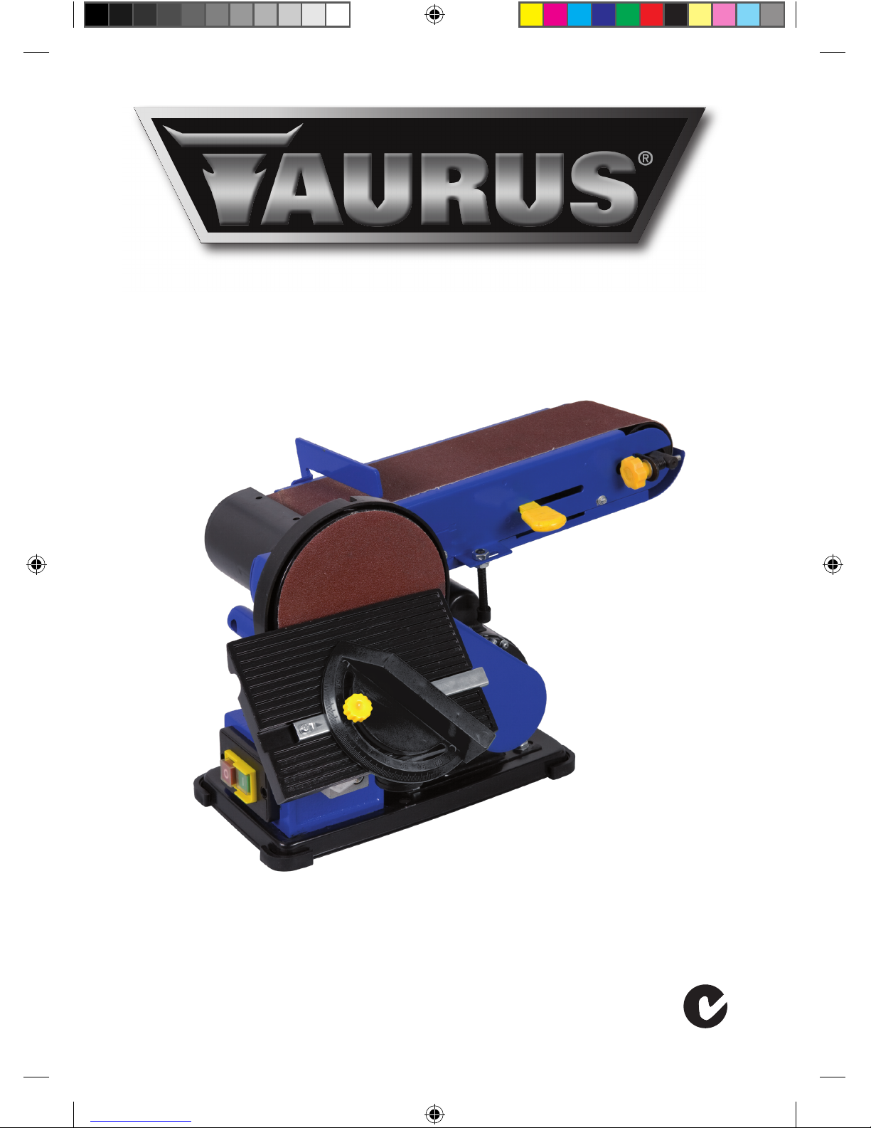
FEATURES
1. Machine frame
2. Motor
3. Roller stop and parallel stop
4. Clamping handle
5. Transport roller
6. Sanding belt
7 On/off switch
8. Fence
9. Drive roller
10. Aluminium disc
11. Sanding disc
12. Work plate
13. Mitre scale
14. Supporting arm
4
3
11
10
13
12
14
5
6
8
9
2
1
7
Fig. A
BGM6019 Ma 1112-13.indd 11 13-12-2011 08:44:47
Page 12

12Belt & Disc Sander
After Sales Support TEL: 07 3188 2025 WEB: h e l p d e s k @d u o n s .c o m .a u
Fig. B Fig. C
Fig. D Fig. E
BGM6019 Ma 1112-13.indd 12 13-12-2011 08:44:48
Page 13

13Belt & Disc Sander
After Sales Support TEL: 07 3188 2025 WEB: h e l p d e s k @d u o n s .c o m .a u
15
Fig. F Fig. G
Fig. H
BGM6019 Ma 1112-13.indd 13 13-12-2011 08:44:49
Page 14

14Belt & Disc Sander
After Sales Support TEL: 07 3188 2025 WEB: h e l p d e s k @d u o n s .c o m .a u
OPERATING INSTRUCTIONS
Switching On/Off
Press the switch into position ‘1’ to put your sanding machine into operation.•
To switch off the machine the same switch needs to be pressed to position ‘0’.•
Always keep the mains cable away from moving parts.•
There is no need to apply any pressure with the workpiece, because this only slows down •
the speed of the sanding disc.
Sanding
The sanding belt and disc supplied with this sanding machine are suitable for the sanding of
metal, wood or synthetic surfaces. The workpiece should always be held firmly during sanding.
No extra pressure is needed. Guide the work piece up and down over the sanding belt, in order
to prevent the sanding belt and plate from wearing through in one place. Round objects can be
sanded at the ends of the sanding belt. Work pieces which are longer than the sanding
machine can be sanded by removing the fence.
NB: To prevent splintering, wood always needs to be sanded in the longitudinal direction of the
grain.
To treat a very soft surface, there is a very handy method to ‘bring the particles to the surface’.
This is done as follows: wet the already sanded surface with a cloth or sponge and let it dry well.
Some wood fibres will swell up more than others, which leads to a rougher surface than before.
Now the higher particles are treated with fine sanding paper, the result is a remarkably smooth
surface. This method should not be applied with varnished wood, however, because the
varnish may come loose because of the moisture.
FREQUENTLY ASKED QUESTIONS
What do I need to do when the motor becomes hot and cuts out?
Wait several minutes until the machine has cooled down, and then restart the machine. If •
this does not work, contact the customer service helpline.
What do I need to do when I switch the machine on, but it will not run?
Restart the machine or wait several minutes until the machine has cooled down, and then •
restart the machine. If this does not work, contact the customer service helpline.
BGM6019 Ma 1112-13.indd 14 13-12-2011 08:44:49
Page 15

15Belt & Disc Sander
After Sales Support TEL: 07 3188 2025 WEB: h e l p d e s k @d u o n s .c o m .a u
OTHER USEFULL INFORMATION
Cleaning and maintenance
Before cleaning and maintenance, always switch off the machine and remove the mains
plug from the mains.
Regularly clean the housing with a soft cloth.•
Keep the ventilation slots free from dust and dirt. If necessary, use a soft, moist cloth to •
remove dust and dirt from the ventilation slots.
Regularly clean the cutting discs to avoid inaccuracies during use.•
Warranty
Consult the enclosed warranty terms.
Environment
The product, the accessories, and the packaging must be sorted for environmentally
friendly recycling.
Only for EC countries
Do not dispose of power tools into domestic waste. According to the European Guideline
2002/96/EC for Waste Electrical and Electronic Equipment and its implementation into national
right, power tools that are no longer usable must be collected separately and disposed of in an
environmentally friendly way.
The product and the user manual are subject to change. Specifications can be changed
without further notice.
BGM6019 Ma 1112-13.indd 15 13-12-2011 08:44:49
Page 16

16Belt & Disc Sander
After Sales Support TEL: 07 3188 2025 WEB: h e l p d e s k @d u o n s .c o m .a u
DECLARATION OF CONFORMITY
(GB) We declare under our sole responsibility that this product is in conformity and accordance with the following
standards and regulations:
EN610291, EN550141, EN550142, EN6100032, EN6100033
2006/42/EC, 2006/95/EC, 2004/108/EC, 2002/96/EC, 2002/95/EC
Zwolle, 01-08-2011
I. Mönnink
CEO Ferm BV
It is our policy to continuously improve our products and we therefore reserve the right to
change the product specification without prior notice.
Ferm BV • Lingenstraat 6 • 8028 PM • Zwolle The Netherlands
BGM6019 Ma 1112-13.indd 16 13-12-2011 08:44:49
Page 17

17Belt & Disc Sander
After Sales Support TEL: 07 3188 2025 WEB: h e l p d e s k @d u o n s .c o m .a u
BGM6019 Ma 1112-13.indd 17 13-12-2011 08:44:49
Page 18

18Belt & Disc Sander
After Sales Support TEL: 07 3188 2025 WEB: h e l p d e s k @d u o n s .c o m .a u
BGM6019 Ma 1112-13.indd 18 13-12-2011 08:44:49
Page 19

19Belt & Disc Sander
After Sales Support TEL: 07 3188 2025 WEB: h e l p d e s k @d u o n s .c o m .a u
BGM6019 Ma 1112-13.indd 19 13-12-2011 08:44:49
Page 20

After Sales Support TEL: 07 3188 2025 WEB: h e l p d e s k @d u o n s .c o m .a u
1112-13
BGM6019 Ma 1112-13.indd 20 13-12-2011 08:44:49
 Loading...