

Page 1
Assembly and operating instructions
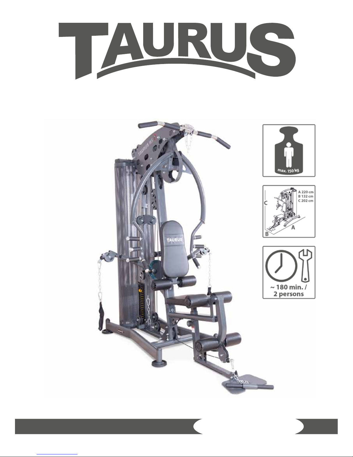
Multi-gym WS7
TF-WS7-2
Page 2

WS7
2
Page 3

3
Dear Customer,
Thank you for deciding for a high-quality training equipment of the brand Taurus,
the brand that makes athlete‘s hearts beat faster. Taurus oers a wide range of home
tness equipment like elliptical cross trainers, ergometers, treadmills and rowing
machines. Taurus equipment is the optimal equipment for all those who want to train
at home independent of goals and tness level. For further information please visit
www.sport-tiedje.com or www.taurus-tness.de.
SAFETY NOTICE
Please read all of the instructions carefully before assembly and rst
use. These instructions are intended to ensure speedy assembly and
explain safe usage. Make sure that all people exercising with the
equipment (in particular children and persons with limited physical, sensory, mental or
motor capabilities) are informed about these instructions and its content in advance.
In case of doubt, a responsible person must supervise the use of the equipment.
This equipment has been manufactured according to the latest safety knowledge. As
far as possible, potential safety hazards which could cause injury have been eliminated.
Make sure to follow the instructions carefully and that all parts are securely in place. If
required, read through the instructions again to correct any mistakes.
Please pay close attention to the safety and maintenance instructions given here. The
contract partner cannot be held liable for damage to health, accidents or damage to
the equipment when it is not used in accordance with these instructions.
The equipment is only suitable for use at home. The equipment is not suitable for
semi-professional (e. g., hospitals, clubs, hotels, schools, etc.) and commercial or
professional use (e. g., health clubs).
Retain these instructions in a safe place for future reference, maintenance or when
ordering replacement parts.
Page 4

WS7
4
Page 5

5
CONTENTS
1 GENERAL INFORMATION 6
1.1 Technical data 6
1.2 Personal safety 7
1.3 Set-up place 8
2 ASSEMBLY INSTRUCTIONS, MAINTENANCE AND CARE 9
2.1 Workout exercises 9
2.2 Faults and Troubleshooting 10
2.3 Maintenance and service calendar 11
3 ASSEMBLY 12
4 WORKOUT INSTRUCTIONS 50
4.1 Workout exercises 50
4.2 Stretching exercises for leg and chest muscles 54
4.3 Workout journal 56
5 WARRANTY INFORMATION 57
6 DISPOSAL 59
7 ORDERING ACCESSORIES 60
8 ORDERING SPARE PARTS 61
8.1 Service hotline 61
8.2 Serial number and model name 61
8.3 Parts list 62
8.4 Exploded drawing 65
Page 6

WS7
6
1 GENERAL INFORMATION
1.1 Technical data
Weight and dimensions:
Weight and dimensions:
Item weight (gross, incl. packaging): 249 kg
Item weight (net, without packaging): 233 kg
Weight stack in kg: 90 kg
Packed dimensions boxes (length x width x height):
No. 1 approx. 195 cm x 47 cm x 22 cm
No. 2 approx. 139 cm x 93 cm x 28.5 cm
No. 3 approx. 181.5 cm x 30 cm x 20 cm
No. 4 approx. 28.5 cm x 13 cm x 13.5 cm
No. 5 approx. 28.5 cm x 13 cm x 13.5 cm
No. 6 approx. 28.5 cm x 13 cm x 13.5 cm
Set-up dimensions (length x width x height): approx. 220 cm x 132 cm x 202 cm
Maximum user weight: 150 kg/330 lbs
Page 7

7
1.2 Personal safety
+ Before you start using the equipment, you should consult your physician that this
type of exercise is suitable for you from a health perspective. Particularly aected
are persons who: have a hereditary disposition to high blood pressure or heart
disease, are over the age of 45, smoke, have high cholesterol values, are overweight
and/or have not exercised regularly in the past year.
+ Please note that working out excessively can seriously damage your health.
+ The equipment may only be used for its intended purpose; this means for strength
training for adults.
+ Any other usage is prohibited and potentially dangerous. The contract partner
cannot be held liable for damage resulting from improper use.
+ The equipment may not be used by several persons at the same time.
+ Children should not be allowed unsupervised access to the equipment.
+ Before starting your training, make yourself familiar with all of the equipment‘s
functions and setting options. Have an expert explain the correct usage of the
product to you.
+ Make sure that nobody is in the range of motion of the equipment while exercising.
+ Keep your hands, feet and other body parts, hair, clothing, jewelry and other
objects well clear of moving parts.
+ During use, wear suitable sports clothing rather than loose or baggy clothing.
When selecting sports shoes, think about the suitability of the sole – preferably
this should be made of rubber or other non-slip materials. Shoes with heels, leather
soles, studs or spikes are not suitable. Never work out in bare feet.
+ It is also important to take note of the information given in the workout instructions
for creating a workout plan.
+ At the rst signs of weakness, nausea, dizziness, pain, diculty in breathing or
other abnormal symptoms, stop your workout immediately and, if necessary,
consult your physician.
+ Before each training session, check all cables for any possible damage. Immediately
replace defective cables and do not use the equipment until it has been repaired.
Also pay attention to any material fatigue.
+ Never let go of the handlebars or grips as long as there is resistance in order to
avoid crushing and similar injuries.
+ Make sure that the cables are always in the wheel guide. If the cables are stuck
while you are training, stop training immediately and check the cable run.
+ If you adjust the seat, make sure that it fully locks in its new position, because
otherwise it may slide and lead to injuries.
Page 8

WS7
8
1.3 Set-up place
+ The equipment should only be used indoors, in a suciently heated and dry area
(ambient temperature between 10°C and 35°C). The equipment should not be
used outdoors or in rooms with high humidity (over 70%) like swimming pools. The
equipment should only be stored in surroundings with an ambient temperature
between 5°C and 45°C.
+ The training room should be well ventilated during training and not be exposed to
any draughts.
+ Choose a location in which to place the equipment such that there is enough free
space/clearance to the front, the rear and to the sides of the equipment (at least
1.50 m). Furthermore, the equipment should not be set up in main entrances or on
escape routes.
+ No objects of any type should be inserted into the openings of the equipment.
+ The equipment should be placed on a level and solid surface, any unevenness in
the oor should be leveled out.
+ A oor protective mat / equipment underlay can help to protect high-quality oor
coverings (parquet, laminate, cork, carpets) from dents and sweat and can help to
level out slight unevenness.
2
Page 9

9
2 ASSEMBLY INSTRUCTIONS, MAINTENANCE AND CARE
2.1 General instructions
+ Please check if all parts and tools belonging to the equipment are included in the
delivery and if there is any transport damage. If there are any complaints, please
contact your contract partner directly.
+ Some of the nuts and bolts to be used in assembly are already pre-mounted in
order to make set-up as easy as possible.
+ The equipment must be assembled by adults. In case of doubt, ask for assistance
from another person with technical skills.
+ Keep children away from the equipment during assembly, because small parts are
included in the delivery and may be swallowed.
+ Make sure that you have enough space (at least 1.50 m) in every direction during
assembly.
+ Do not leave any tools and packaging materials like plastic sheeting laying around
to avoid danger of suocation for children.
+ Assemble the equipment on an underlay mat or on the cardboard packaging in
order to avoid damage to the equipment and to the oor (scratches).
+ Before starting assembly, all individual parts should be placed on the oor next to
each other.
+ Read the assembly instructions carefully and assemble the equipment according
to the illustrations. Proceed carefully and cautiously.
+ First loosen all parts and check for their correct tting. Then tighten the screws
using a tool.
+ Modications to the design or improper repairs may pose a hazard to the user and
should not be carried out. The product warranty may be void as a result.
+ Only authorized service technicians are permitted to carry out all servicing and/or
repairs – it excludes maintenance and care.
+ Damaged or worn components may impair your safety and the lifespan of
the equipment. You should therefore immediately replace damaged or worn
components. Please contact your contract partner in such a case. The equipment
should no longer be used until it has been repaired. When needed, only use
original Taurus spare parts.
+ Check the tightness of all screw connections once a month.
+ In order to be able to guarantee the constructively dened safety level of this
equipment, we recommend having the equipment regularly maintained (at least
once a year) by specialists (service technicians of your contract partner).
Page 10

WS7
10
+ The equipment may be cleaned of dust, dirt and sweat using a damp cloth. The
use of solvents should be strictly avoided. Also, make sure that no liquids (e. g.
sweat) get into the openings of the equipment.
2.2 Faults and Troubleshooting
The equipment runs through regular quality controls during production. Nevertheless,
errors or malfunctions on the equipment may occur. Individual parts are often the
cause of faults and replacement is usually sucient. Please use the following overview
to see the four most common errors and how to repair them. If the equipment still
does not work properly, please contact your contract partner.
Problem Cause Solution
Scraping noises
Cable or pulleys not
running smoothly or are
damaged
Perform a visual check of the route
of the cable or of the pulley or of
the pulley guide
Weight is
suspended in the
air
Cable is too tightly
stretched
Readjust cable tension
Cable is not taut Cable is too slack Readjust cable tension
Squeaking &
cracking noises
Screws are either too
loose or too tight
Check that screws are correctly
tightened or lubricate
Page 11

11
2.3 Maintenance and service calendar
The multi-gym needs to be cleaned after every training session with a moist towel (no
solvent!) in order to avoid damage caused by sweat.
The following routine work must be done in the specied time intervals:
Part Weekly Weekly 2x annually Annually
Pulling ropes and rollers C / I
Bolts
I
Pulleys and cable guide
I
Legends: C = cleaning; I = inspect
Page 12
WS7
12
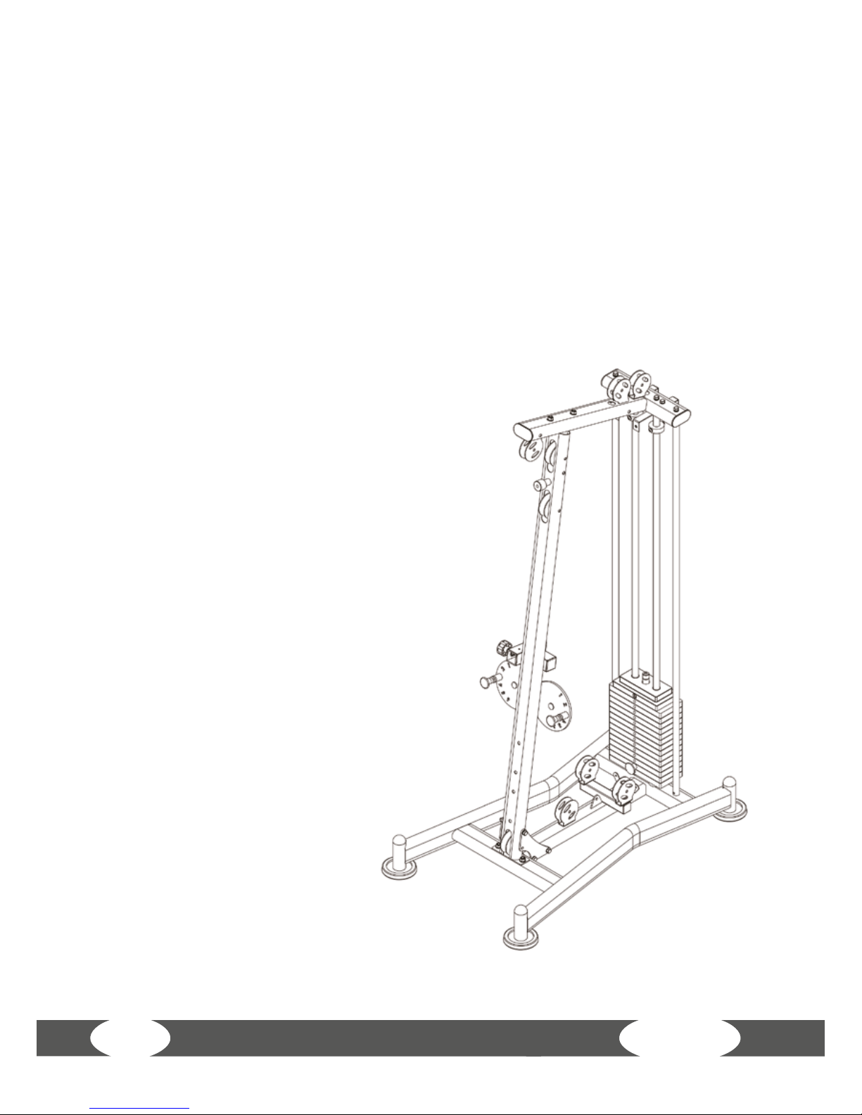
3 ASSEMBLY
In order to make the assembly of the equipment easier, we recommend that you
do not initially fully tighten the screws and bolts. However, you should make
sure that all screws and bolts are rmly tightened after assembly.
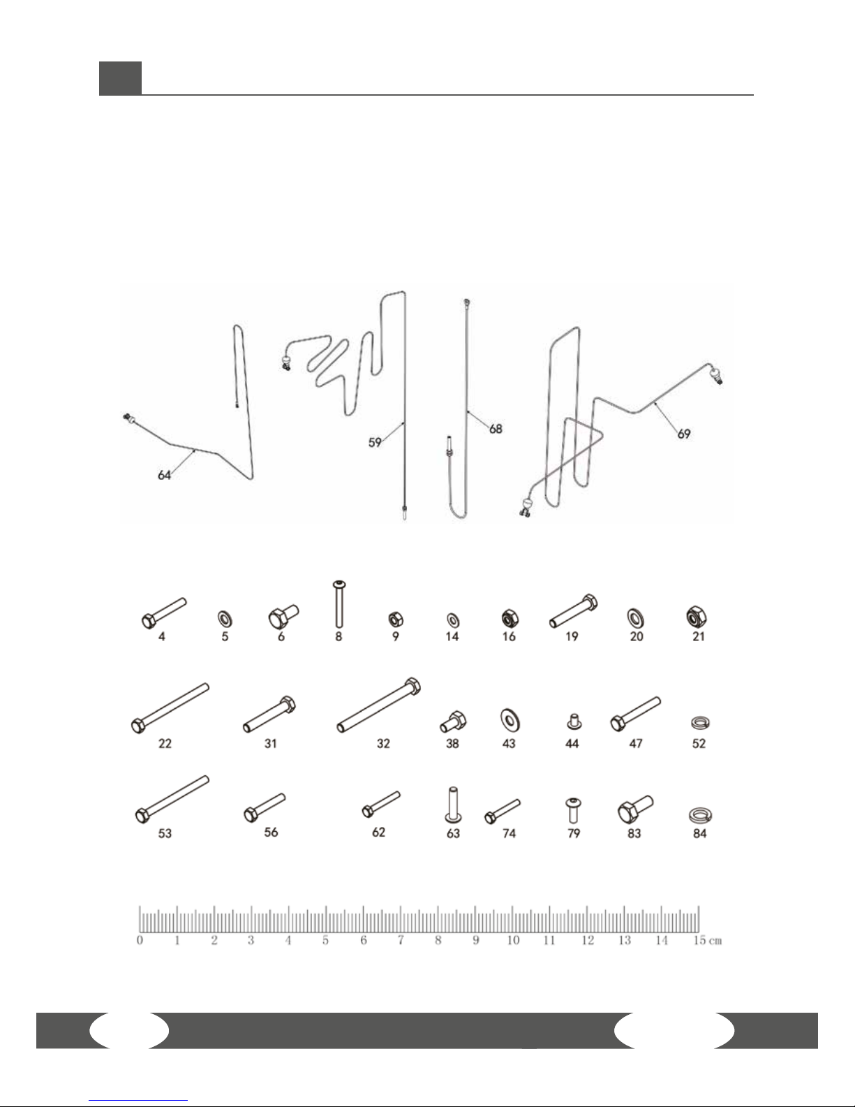
Screws and cables overview
Page 13
13
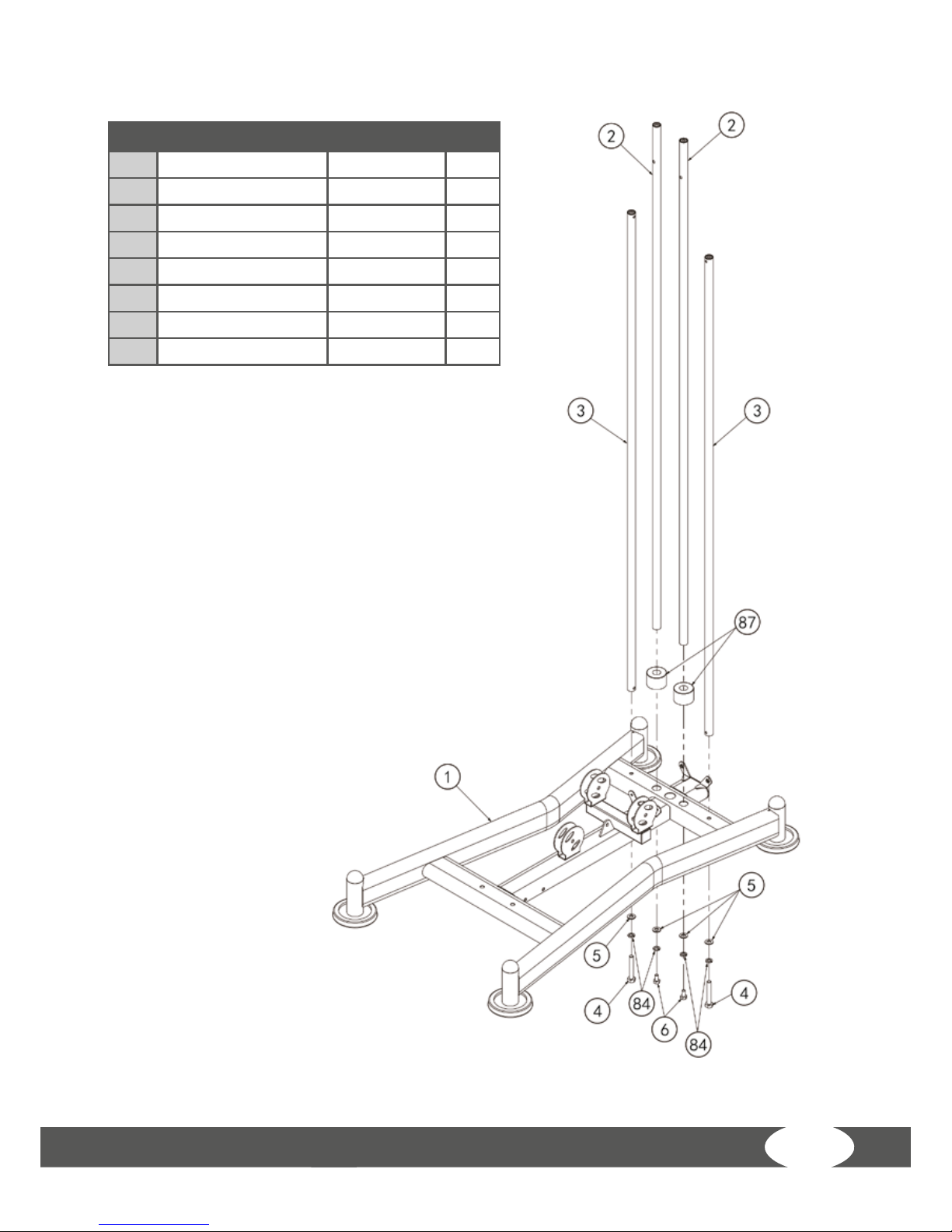
Step 1: Exploded drawing
No. Description Note
Qty.
1 ground frame 1
2 guide bar Φ25*1853 2
3 back support tube Φ259*1757.5 2
4 outer hexagon bolt M10*65 2
5 shim Φ10 4
6 outer hexagon bolt M10*20 2
84 spring shim Φ10 4
87 cushion Φ60*Φ26*42 2
Page 14
WS7
14
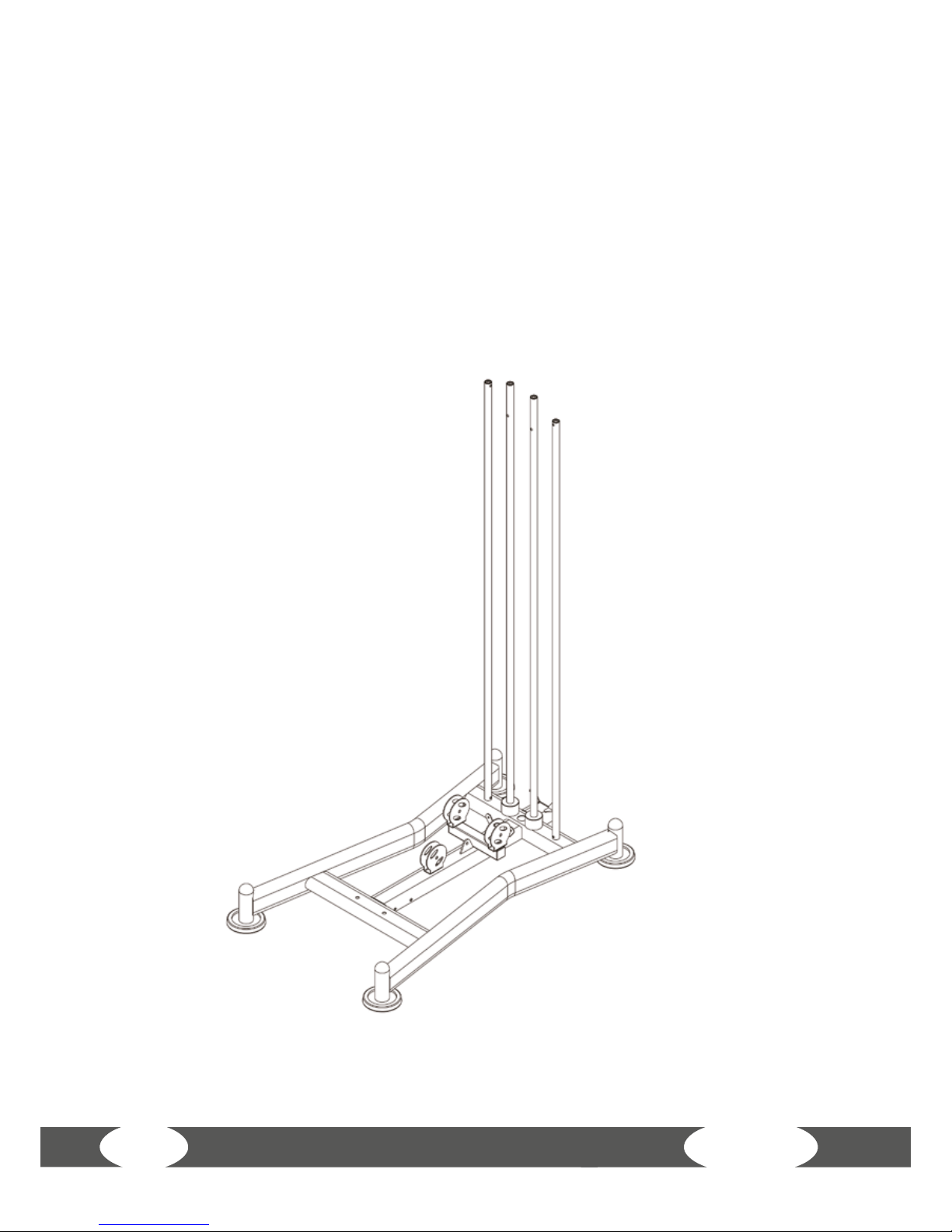
Step 1: Assembly
1. Mount the rear support struts (3) to the base frame (1) using hexagon bolts M10*65
(4), (4), spring washers Φ10 (84) and washers Φ10 (5).
2. Secure the guide rods (2) to the base frame (1) using hexagon bolts M10*20 (6),
spring washers Φ10 (84) and washers Φ10 (5).
3. Slide the rubber dampers (87) on the guide rods (2) from the top down to the very
bottom.
Page 15
15
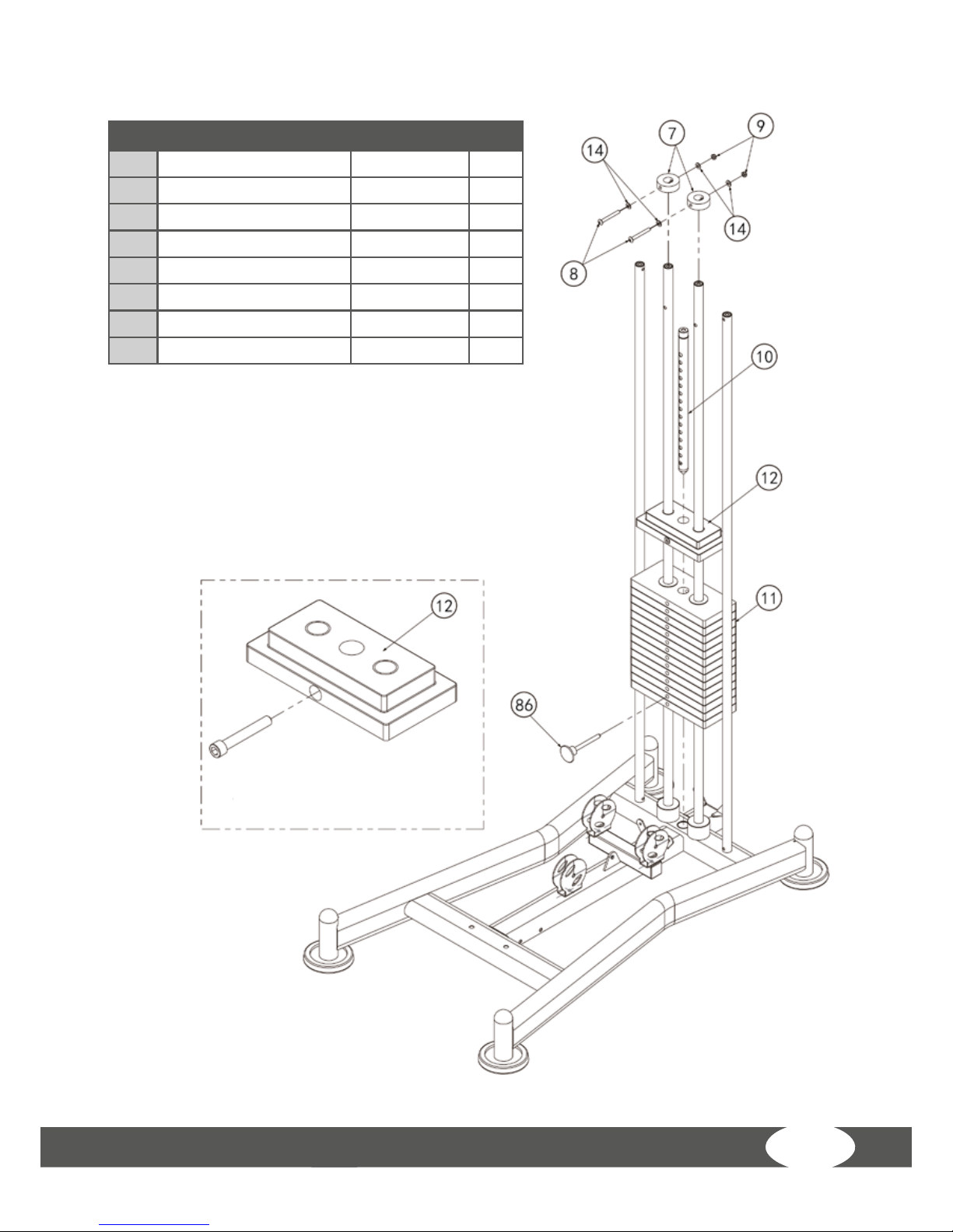
Step 2: Exploded drawing
No. Description Note
Qty.
7 weight stack rubber crash Φ60*Φ26*20 2
8 hexagon sock button head M8*70 2
9 lock nut M8 2
10 weight stack lift bar 92 KG 1
11 below steel weight stack 6 KG 14
12 top steel weight stack 8 KG 1
14 shim Φ8 4
86 magnetic pin Φ10*100 1
Upper steel weight stack (12)
Partially enlarged drawing
Page 16
WS7
16
Step 2: Assembly
1. Guide the 14 6-kg weight plates (11) carefully down the two guide rods (2); nally
set the single 8-kg weight stack (12) on the top.
Ideally, the weight stacks should be labeled before they are put in place; arrange
the stacks so that the heaviest weight is at the bottom. The writing should be
visible from the front.
2. Remove the screw from the topmost weight stack (12), lower the steel lifting
rod/strut (10) into the central opening in the weight stack and secure it in place by
screwing the screw back into the upper weight stack (12).
3. Secure the two upper rubber stoppers (7) in the topmost hole in the guide rods
(2) using – in each case – one hexagon bolt M8* (8), two
washers Φ8 (14) and one locking nut (9).
4. Insert the magnetic safety pin (86) into the front of the
second-to-bottom weight plate.
Page 17
17
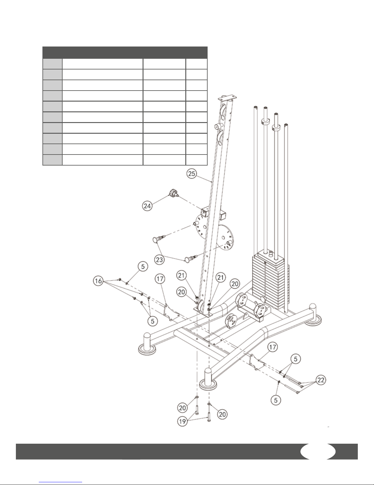
Step 3: Exploded drawing
No. Description Note
Qty.
5 shim Φ10 6
16 luck out M10 3
17 side support xing plate 2
19 outer hexagon bolt M12*70 2
20 shim Φ12 4
21 luck out M12 2
22 outer hexagon bolt M10*130 3
23 umbrella shape lock pin 2
24 plum ower pull pin M18*1.5 Φ10 1
25 inclined support frame 1
Page 18

WS7
18
Step 3: Assembly
1. Mount the diagonal, front frame section (25) to the base frame (1) using hexagon
bolts M12*70 (19), washers Φ12 (20) and locking nuts M12 (21).
2. Mount the two side mounting plates (17) to the diagonal, front frame section (25)
and to the base frame (1) using three hexagon bolts M10*130 (22), six washers Φ10 (5)
and three locking nuts M10 (16).
3. Mount the two locking pins (23) to the two circular plates on the front of the frame
section (25).
4. Mount the pull pin/retaining pin (24) to the diagonal, front frame section (25).
Page 19
19
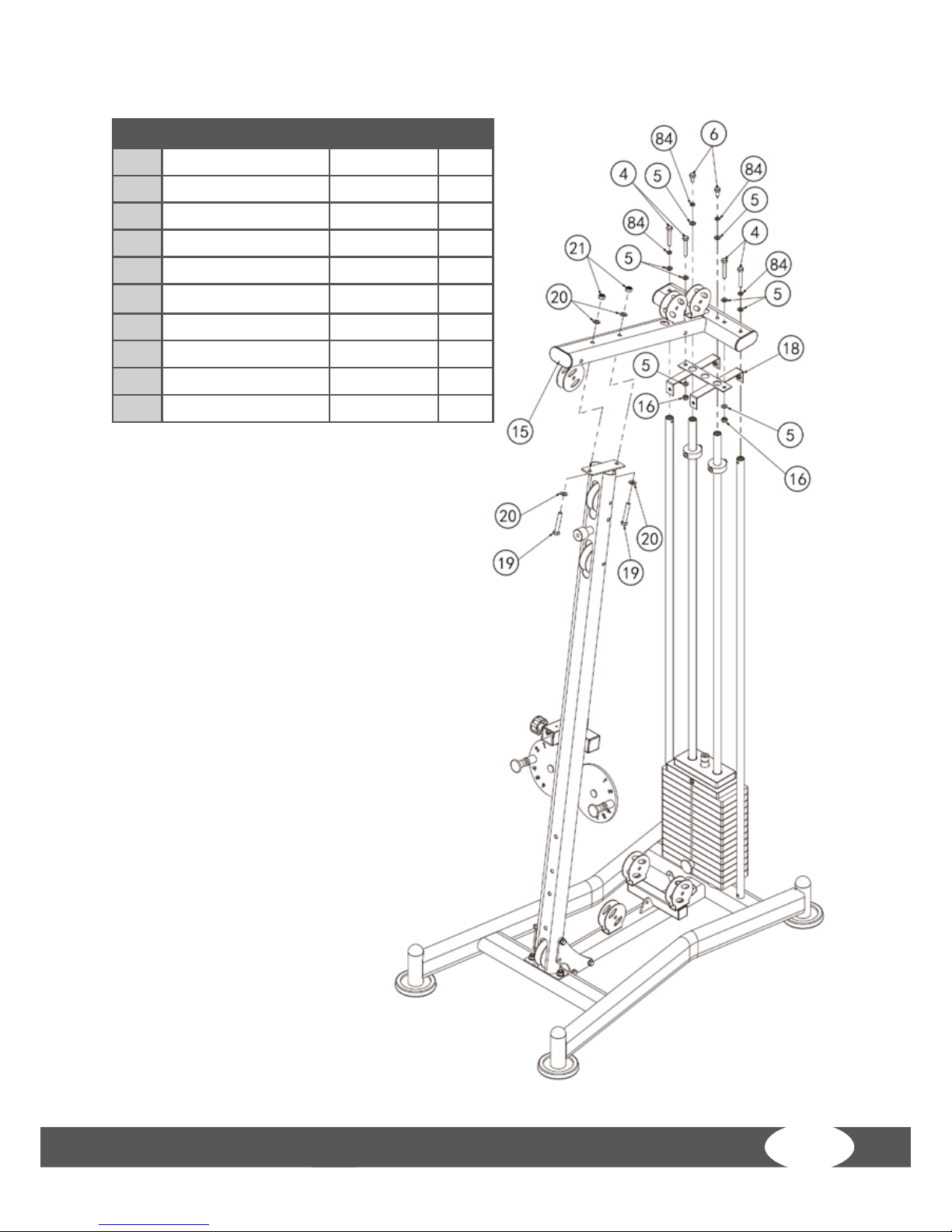
Step 4: Exploded drawing
No. Description Note
Qty.
4 outer hexagon bolt M10*65 4
5 shim Φ10 8
6 outer hexagon bolt M10*20 2
15 upper frame weldment 1
16 luck out M10 2
18 sheild support frame 1
19 outer hexagon bolt M12*70 2
20 shim Φ12 4
21 luck out M12 2
84 spring shim Φ10 4
Page 20
WS7
20
Step 4: Assembly
1. Push the mounting for the weight stack cover (18) onto the guide rods.
2. Place the upper connecting frame (15) on the guide rods and the front, diagonal
frame. Mount the upper frame to the guide rods using two hexagon bolts M10*20 (6),
two washers Φ10 (5) and two spring washers Φ10 (84).
3. Mount the upper frame (15) to the front frame using two hexagon bolts M12*70
(19), two washers Φ12 (20) and two locking nuts M12 (21).
4. Mount the upper frame (15) to the rear support struts (3) using two hexagon bolts
M10*65 (4), two washers Φ10 (5) and two spring washers Φ10 (84).
5. Mount the holder for the weight stack cover
(18) to the upper frame (15) using two hexagon
bolts M10*65 (4), two washers Φ10 (5) and two
locking nuts M10 (16).
Page 21
21
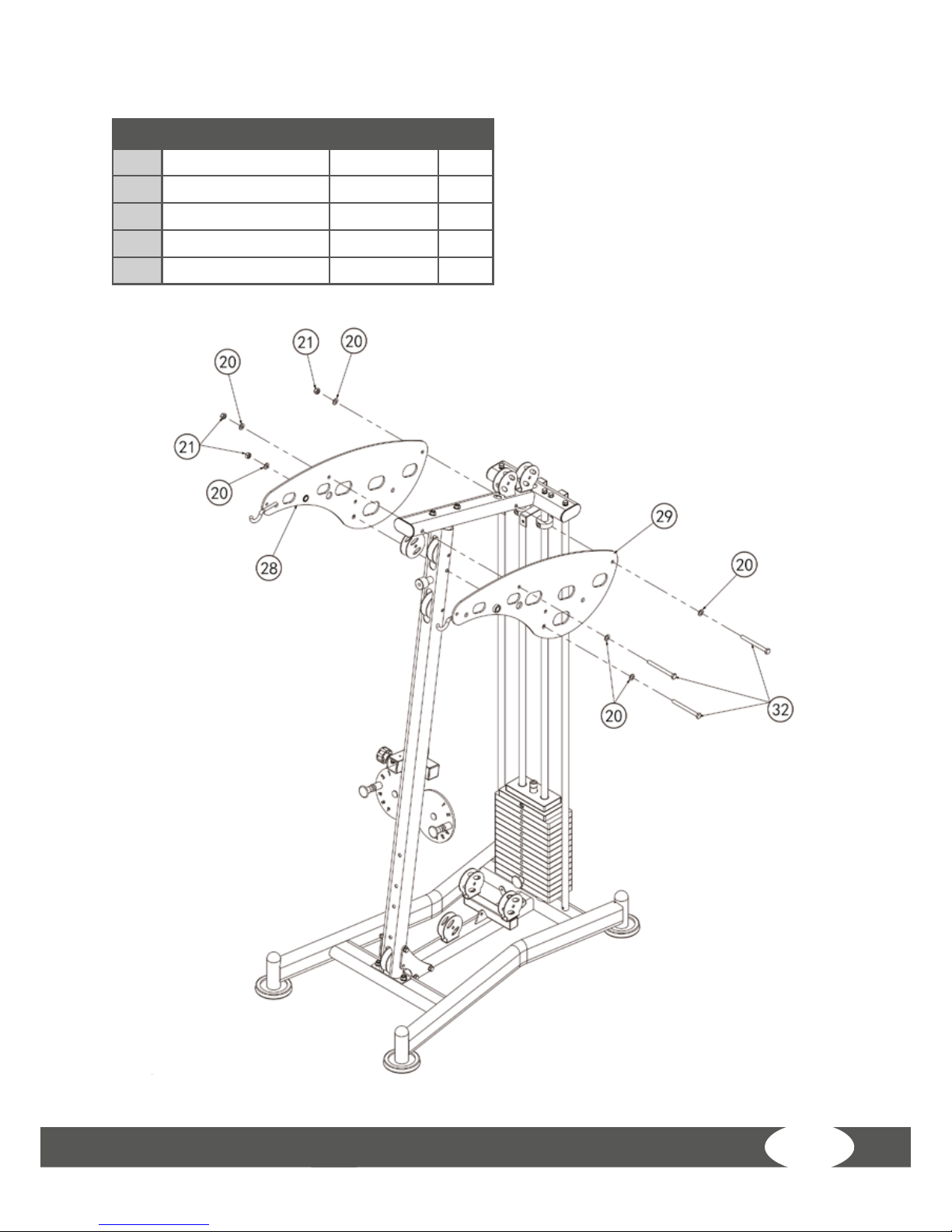
Step 5: Exploded drawing
No. Description Note
Qty.
20 shim Φ12 6
21 luck out M12 3
28 right decorative plate M10*20 1
29 left decorative plate 1
32 outer hexagon bolt M12*130 3
Page 22

WS7
22
Step 5: Assembly
Mount the right cover (28) and the left cover (27) onto the upper frame using three
hexagon bolts M12*130 (32), six washers Φ12 (20) and three locking nuts M12 (21).
Page 23

23
Step 6: Exploded drawing
No. Description Note
Qty.
5 shim Φ10 2
20 shim Φ12 4
21 luck out M12 2
24 plum ower pull pin
M18*1.5
Φ10 1
26 saet cushion adjust
frame
1
27 leg curl bending tube 1
30 axis of rotation Φ17*57 1
31 outer hexagon bolt M12*75 2
33 seat cushion tube 1
83 outer hexagon bolt M10*25 2
84 spring shim Φ10 2
Page 24

WS7
24
Step 6: Assembly
1. Mount the seat upholstery holder (33) to the front frame using hexagon bolts
M12*75 (31), washers Φ12 (20) and locking nuts M12 (21).
2. Push the bushing (30) into the leg-curl holder (27).
3. Insert the leg-curl sloping bar (27) into the seat upholstery holder (33) using
hexagon bolts M10*25 (83), spring washers Φ10 (84) and washers Φ10 (5).
4. Mount the seat upholstery adjustment frame (26) to the seat upholstery holder (33)
using the locking screw (24).
Page 25

25
Step 7: Exploded drawing
No. Description Note
Qty.
6 outer hexagon bolt M10*20 4
14 shim Φ8 1
36 front push frame holder 1
37 front push holder axle Φ17*134 1
38 outer hexagon bolt M8*16 1
39 front push arm 1
40 front push frame axle Φ17*100 1
41 labeling arc plate 1
43 big shim Φ25*10*2.0 4
82 plum ower pull pin-M18*1.5 Φ12 1
84 spring shim Φ10 2
Page 26
WS7
26
Step 7: Assembly
1. Using the shaft (37), connect chest-press mount (36) to the covers and, using
hexagon bolts M10*20 (6), spring washers Φ10 (84) and the large washers Φ10 (43),
x both ends to the front mount shaft (37).
2. Connect chest-press module (39) to chest-press mount (36) using the front bushings
(40). Secure to the bushing (40) on both sides using the hexagon bolts M10*20 (6) and
large washers Φ10 (43). Fix retaining pin (82) to the chest-press module (39).
3. Mount guard plate (41) to the chest-press mount (36) using the hexagon bolt
M8*16 (38) and washer Φ8 (14).
Page 27
27
Step 8: Exploded drawing
No. Description Note
Qty.
5 shim Φ10 2
16 luck out M10 1
20 shim Φ12 4
21 luck out M12 2
31 outer hexagon bolt M12*75 2
34 buttery arm-right 1
35 buttery arm-left 1
42 pulley support frame 1
43 big shim Φ25*10*2.0 2
44 hexagon sock button head bolt M10*16 2
45 long semicircle plate 1
46 feet pad 1
47 outer hexagon bolt M10*70 1
84 spring shim Φ10 2
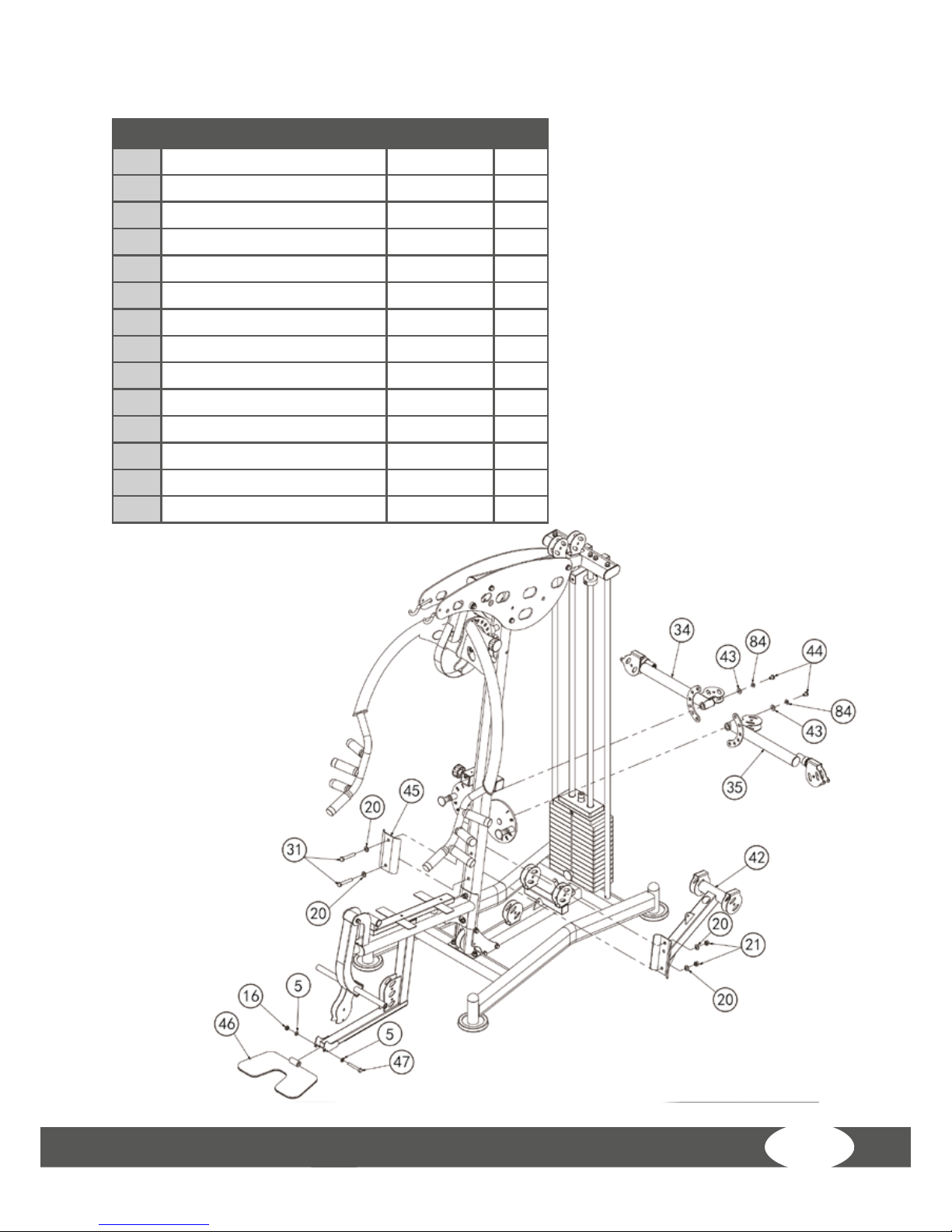
Page 28

WS7
28
Step 8: Assembly
1. Mount the left buttery arm (35) to the front frame using hexagon bolt M10*16
(44), spring washer Φ10 (84) and large washer Φ10 (43).
2. Mount the right buttery arm (34) to the front frame using hexagon bolt M10*16
(44), spring washer Φ10 (84) and large washer Φ10 (43).
3. Mount the reinforcing plate (45) to the front of the frame using hexagon bolts
M12*75 (31) and washers Φ12 (20). On the other side, place the supporting frame on
the guide-pulley mount (42) and secure using washers Φ12 (20) and locking nuts Φ12
(21).
4. Mount the footplate (46) to the front
of the seat frame using hexagon bolt
M12*70 (47), washer Φ10 (5) and locking
nut M10 (16).
Page 29

29
Step 9: Exploded drawing
No. Description Note
Qty.
5 shim Φ10 2
16 luck out M10 31
22 outer hexagon
bolt
M10*130 8
48 “-” shape pulley
frame
2
49 pulley Φ95*26 25
50 link sleeve Φ14*100 1
53 outer hexagon
bolt
M10*115 1
56 outer hexagon
bolt
M10*45 19
58 pulley spacer
sleeve
Φ22*Φ10.5*
45.5
4
59 lat pull cable L:4540mm 1
63 hexagon sock
button head bolt
M10*45 1
Page 30
WS7
30
Step 9: Exploded drawing
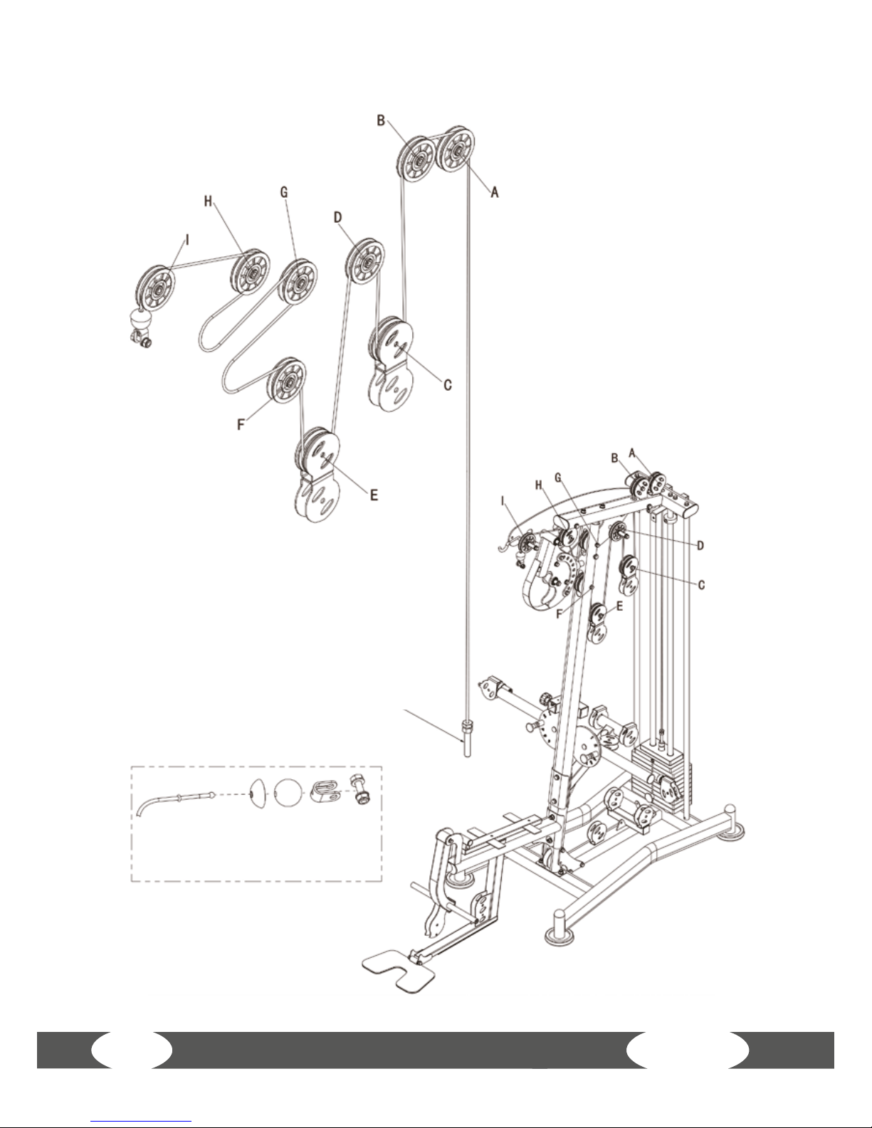
Lat-pull cable end
Lat-pull cable drawing
Page 31

31
Step 9: Assembly
1. Mount two guide pulleys A, B (49) in the guide-pulley frames (48) using hexagon
bolts M10*45 (56), washers Φ10 (5) and locking nuts M10 (16). Likewise mount two
guide pulleys C, E (49) in the guide-pulley frames using hexagon bolts M10*45 (56),
washers Φ10 (5) and locking nuts M10 (16).
2. Mount two guide pulleys I, D (49) to the frame using hexagon bolts M10*130 (22),
guide-pulley spacers (58), washers Φ10 (5) and nuts M10 (16).
3. Mount the guide pulley G (49) to the front frame using hexagon bolt M10*130 (22),
washers Φ10 (5) and locking nuts M10 (16).
4. Mount the guide pulley H (49) to the frame using hexagon bolt M10*45 (63),
washers Φ10 (5) and locking nuts M10 (16).
5. Mount the guide pulley F (49)
to the frame using hexagon bolt
M10*115 (53), washers Φ10 (5) and
locking nut M10 (16).
6. Attach one hexagon bolt
M10*130 (22) to the left cover (near
point I) using connecting tube (50),
washer Φ10 (5) and nut M10 (16).
7. Connect the lat-pull cable (59)
with the end of the lifting rod /strut.
8. Pull the lat-pull cable (59) over
the guide pulleys (49) in the order
A, B, C, D, E, F, G, H, I; and attach the
end of the lat-pull cable to guide
pulley I (49) (see detail drawing).
Page 32

WS7
32
Step 10: Exploded drawing
No. Description Note
Qty.
5 shim Φ10 12
9 lock nut M8 2
14 shim Φ8 4
16 luck out M10 6
22 outer hexagon bolt M10*130 1
49 pulley Φ95*26 5
56 outer hexagon bolt M10*45 4
60 9 hooks chain 1
62 outer hexagon bolt M8*45 2
64 low pull cable L:3365mm 1
65 short bar 1
83 outer hexagon bolt M10*25 1
Page 33
33
Step 10: Cable run drawing
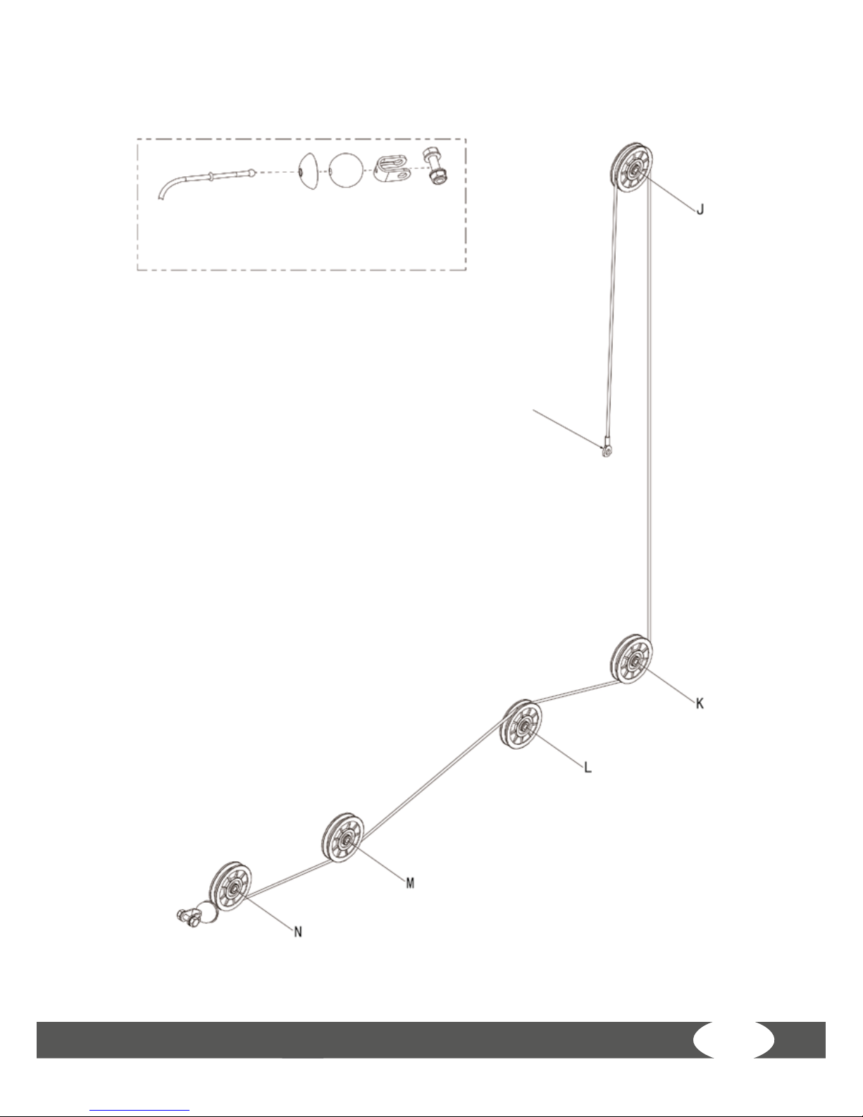
Lower pull cable end
Lower pull cable drawing
Page 34

WS7
34
Step 10: Assembly
1. Mount the guide pulleys J, K, M, N (49) in the brackets on the frame intended for
that purpose, using hexagon bolts M10*45 (56), washers Φ10 (5) and nuts M10 (16)
in each case.
2. Mount the guide pulley L (49) to the frame using hexagon bolt M10*130 (22),
washer Φ10 (5) and nut M10 (16).
3. Mount the upper pull cable end to the guide-pulley supporting frame using
hexagon bolt M10*25 (83), washer Φ10 (5) and nut M10 (16).
4. Pull the lower pull cable end over the guide pulley J, under K, over L and under M
and N; then mount the head end on the cable (see detail drawing).
5. Connect one end of the chain (60) to the head end of the cable using the snap
hook, and the other end to the pull bar (65).
Page 35

35
Step 11: Exploded drawing
No. Description Note
Qty.
5 shim Φ10 6
16 luck out M10 3
49 pulley Φ95*26 3
51 double pulley guide plate 1
56 outer hexagon bolt M10*45 3
60 9 hooks chain 1
66 double pulley plate 1
68 middle cable L:1500mm 1
Page 36

WS7
36
Step 11: Assembly
1. Mount two guide pulleys (49) to the double guide-pulley mount (66) using hexagon
bolts M10*45 (56), washers Φ10 (5) and locking nuts M10 (16).
2. Mount one end of the chain (60) to the pull cable (68) and the other end low down
on the base frame.
3. Guide the pull cable through the opening in the small plate/spacer (51) on the
double guide-pulley mount (66) and then connect the screw end of the pull cable
(66) to the double guide-pulley mount (66). Secure the spacer (51) onto the double
guide-pulley mount (66) using the pre-mounted nut.
4. Place the pull cable (68) between the spacer (51) and the screw end of the cable
via the guide pulley (49). Now secure the guide pulley (49) in 0 position in the guidepulley mount using hexagon bolt M10*45 (56), four washers Φ10 (5) and nut M10 (16).
Page 37

37
Step 12: Exploded drawing
Page 38

WS7
38
Step 12: Exploded drawing
No. Description Note
Qty.
5 shim Φ10 14
9 lock nut M8 2
14 shim Φ8 4
16 luck out M10 6
49 pulley Φ95*26 8
56 outer hexagon bolt M10*45 8
62 outer hexagon bolt M8*45 2
69 buttery arm cable L:5375mm 1
Buttery-arm cable drawing
Page 39

39
Step 12: Assembly
1. Mount the six guide pulleys P, Q, S, U, X, Y (49) in the pulley mounts intended for
that purpose, using hexagon bolts M10*45 (56), washers Φ10 (5) and nuts M10 (16).
2. Mount the two guide pulleys R, W (49) in the pulley mounts intended for that
purpose (nal pulleys on the guide-pulley (42) supporting frame, see page 26), using
hexagon bolts M10*45 (56) and washers Φ10 (5).
3. Starting from point P, guide the pull cable (69), over the guide pulleys in the order:
P, Q, R, S, T, U, W, X, Y. The diagram on page 37 shows the sequence. The pull cable head
end should be removed, where necessary, beforehand (see detail drawing). Points T, U
can be found on the double guide pulley (66) in assembly step 11.
4. Re-attach the pull cable head end.
5. Mount one hexagon bolt M8*45 (62), two washers Φ8 (14) and one nut M8 (9) on
the mounts intended for this purpose on
the end of each of the two buttery arms,
near P and Y.
Page 40
WS7
40
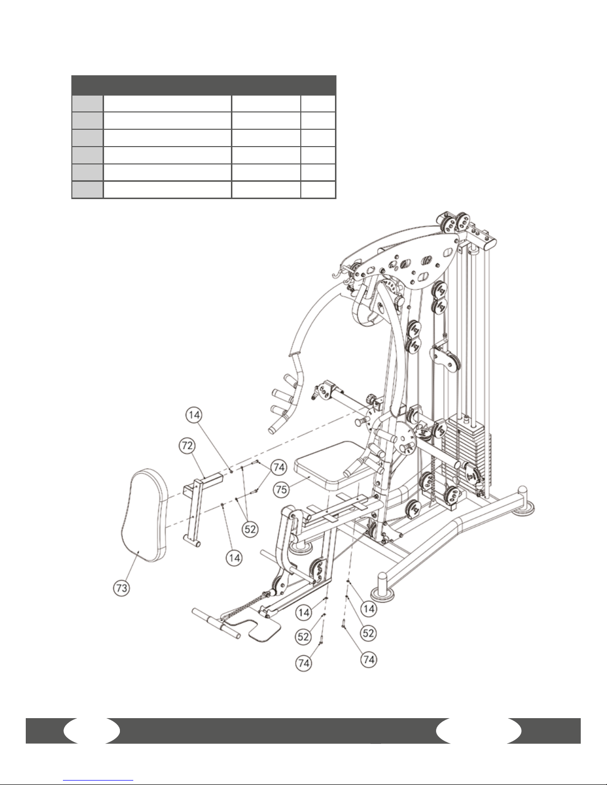
Step 13: Exploded drawing
No. Description Note
Qty.
14 shim Φ8 4
52 spring shim Φ8 4
72 back cushion adjust frame 1
73 back cushion 1
74 outer hexagon bolt M8*40 4
75 seat cushion 1
Page 41
41
Step 13: Assembly
1. Using hexagon bolts M8*40 (74), spring washers Φ8 (52) and washers Φ8 (14),
mount the seat upholstery (75) to the seat upholstery adjustment frame (26) from
page 23.
2. Mount the backrest (73) to the backrest retaining frame (72) using hexagon bolts
M8*40 (74), spring washers Φ8 (52) and washers Φ8 (14).
3. Push the square tube from the retaining frame (72) into the retaining tube on
the front, diagonal frame tube designed for this purpose. If necessary, remove the
retaining pin beforehand, then tighten it up afterwards.
Page 42
WS7
42
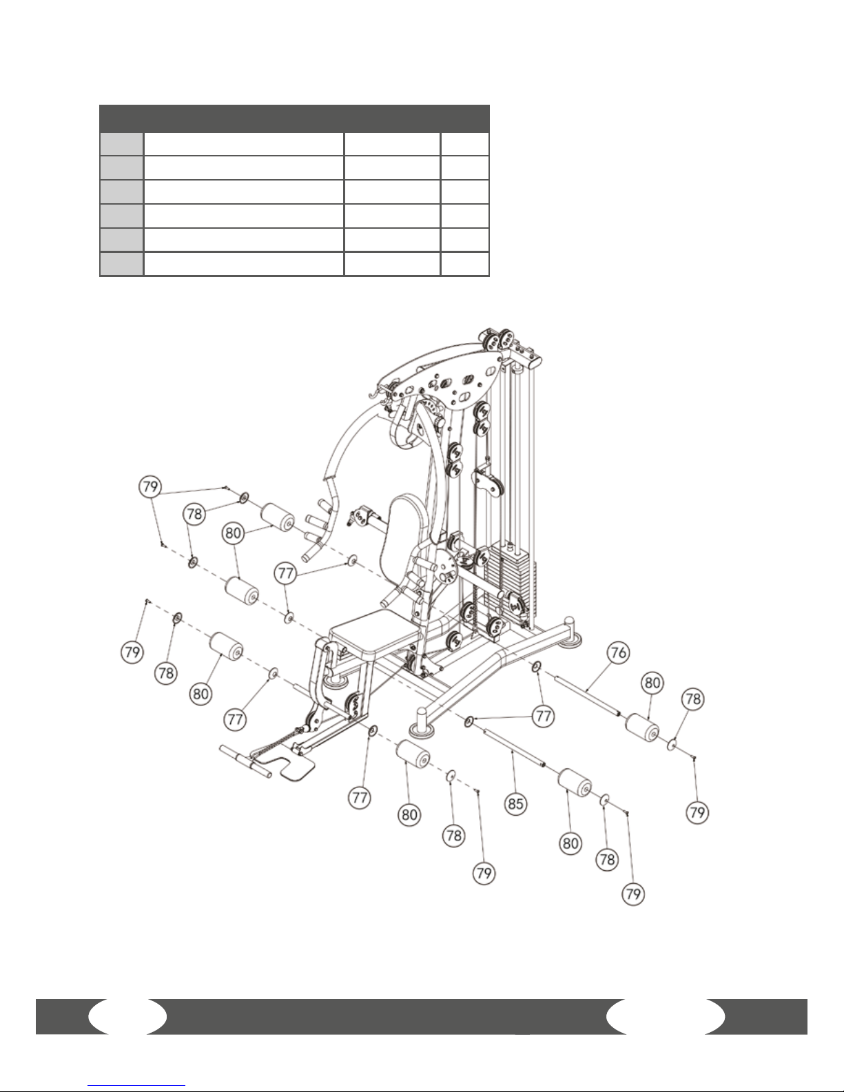
Step 14: Exploded drawing
No. Description Note
Qty.
76 sponge rod tube Φ25*480 1
77 sponge inner cap 6
78 sponge out cap 6
79 hexagon sock button head bolt M8*25 6
80 sponge Φ100*175 6
85 sponge pipe tube Φ25*450 1
Page 43
43
Step 14: Assembly
1. Push the holder of the upholstery rolls (76) into the guide on the backrest mount.
On the xture, turn the upholstery caps inwards (77), the upholstery rolls (80) and the
upholstery caps outwards (78), in order. Attach the upholstery rolls by tightening up
a hexagon bolt M8*28 (79) on both sides.
2. Push the holder of the upholstery rolls (85) into the upper guide on the front of the
seat upholstery. On the xture, turn the upholstery caps inwards (77), the upholstery
rolls (80) and the upholstery caps outwards (78), in order. Attach the upholstery rolls
by tightening up a hexagon bolt M8*28 (79) on both sides.
3. On the xture, at the base of the leg-curl module, turn the upholstery caps inwards
(77), the upholstery rolls (80) and the upholstery caps outwards (78), in order. Attach
the upholstery rolls by tightening up
a hexagon bolt M8*28 (79) on both
sides.
Page 44

WS7
44
Step 15: Exploded drawing
No. Description Note
Qty.
14 shim Φ8 8
38 outer hexagon bolt M8*16 8
52 spring shim Φ8 8
81 sheild 2
Page 45

45
Step 15: Assembly
1. Mount the weight stack cover (81) to the base frame on both sides. For this purpose,
use eight hexagon bolts M8*16, spring washers Φ8 (52) and washers Φ8 (14) in each
case.
Page 46

WS7
46
Step 16: Exploded drawing
No. Description Note
Qty.
60 9 hooks chain 1
61 long bar 1
70 7 hooks chain 2
71 hand pull belt 2
Page 47
47
Step 16: Assembly
1. On both sides, connect the 7-link chains (70) rstly to the end of the buttery arms
with the heads at the end of the pull cable. In each case, connect the other end of the
chain to the handles (71).
2. Connect the 9-link chain (60) to the pull cable head on the top of the lat pull.
Connect the other end of the chain (60) to the lat bar (61). If the lat bar hangs too low
down, you can remove the chain links and just connect the snap hook to the chain.
Page 48

WS7
48
Step 17: Exploded drawing
No. Description Note
Qty.
54 back pull rod weldment 1
55 back pull belt 1
57 hoist hook 3
Page 49
49
Step 17: Assembly
1. If necessary, remove the grips (71) from the buttery arms, including chain (70).
2. Hang the pull bar (54) on the buttery-arm head ends together with the two snap
hooks (57).
3. Now mount the abdominal belt (55) to the pull bar (54) using a snap hook (57).
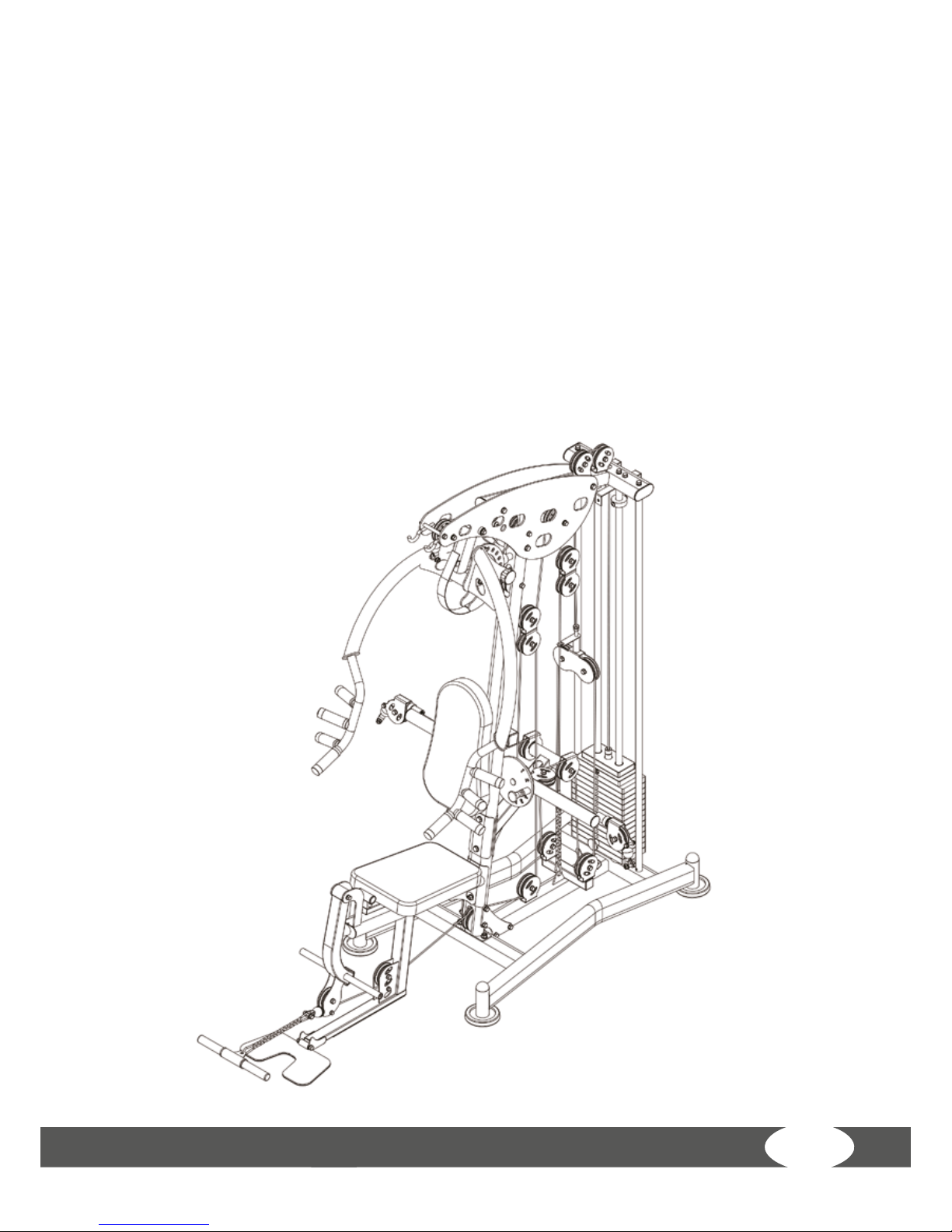
WARNING: When assembly is complete, carry out a further check to ensure that
all of the screws, locking nuts and retaining pins are done up and secure. Then
you can get started with your workout – we hope you enjoy it!
Page 50

WS7
50
4 WORKOUT INSTRUCTIONS
4.1 Workout exercises
1. Seated crunches, start and nish
position:
The lower back maintains contact with
the backrest. Bend your body forward (in
the abdominal muscles) and then return
to the starting position.
2. Seated crunches, reversal point:
When the body is fully bent (in the
abdominal muscles), return to the
starting position. Carry out the exercise
in a slow, controlled manner.
3. Seated buttery, start and nish
position:
Your whole back maintains contact with
the backrest during the exercise. Your
arms should be held almost straight, the
elbow joint is slightly bent. Now bring
your hands together in front of your
chest.
Page 51

51
4. Seated buttery, reversal point:
Just before your hands touch, return
to the starting position. Carry out the
exercise in a slow, controlled manner.
5. Standing one-armed y, start and
nish position:
Take up a steady, relaxed stance. Maintain
tension in your abdominal muscles. Keep
your upper body straight. Keep your arm
almost straight during the exercise. Now
move your hand diagonally in front of
your upper body.
6. Standing one-armed y, reversal
point:
When your hand is at the center in front of
your body, return to the starting position
in a controlled movement.
7. Lat pull to the neck, start and nish
position:
You can vary the grip width in this
exercise. Always keep your arms slightly
bent. Your upper body should be, and
should stay, bent slightly forward. Now
pull the pull-up bar down to your neck.
Do not bend your upper body!
Page 52

WS7
52
8. Lat pull to the neck, reversal point:
Just before the pull-up bar reaches
your neck, stretch your arms back out
again. Carry out the exercise in a slow,
controlled manner.
9. Leg extension, start and nish
position
The upholstery roll should be slightly
above your feet. Now, stretch your legs
in a slow, controlled manner.
10. Leg extension, reversal point:
Never fully straighten your legs to the
point where you lock your knees. As you
return to the start position, do not drop
the weight.
11. Upright cable row, start and nish
position:
Your upper body should be, and should
stay, bent slightly backwards. Your arms
should be held almost straight. Pull the
pull-up bar towards your navel in a slow,
controlled movement. Pull your elbows
in closely passing your body.
Page 53

53
12. Upright cable row, reversal point:
Just before the pull-up bar makes contact
with your trunk, stretch your arms back
out again. Your upper body should still
stay straight.
13. Biceps curl, start and nish
position:
Place your hands in the upper or lower
grip. Your upper body should stay straight
during the exercise. Never fully straighten
your arms to the point where you lock
your elbows. Bend your arms at the
elbow. Keep your elbows xed. Perform
the exercise slowly and controlled.
14. Biceps curl, reversal point:
In a controlled movement, stretch your
arms back out to the starting position. Do
not drop the weight.
Page 54

WS7
54
4.2 Dehnübungen für Bein- & Brustmuskulatur
1. Exercise: Stretching of front thigh / leg extension (quadriceps)
• Stable position, grab arches of feet
• Pull heel towards buttocks, knee points downwards
(no abduction)
• Straight upper body, avoid tilting the pelvic forward
(hollow back) by tensing the abdominal muscles
• Change legs
2. Exercise: Stretching the back thigh / leg curl (hamstring)
• Pull thigh towards upper body with both
hands
• Stretch through increased stretching in
the knee joint
• The lower leg maintains contact with the
oor, keep hips bent
• Change legs
Page 55

55
3. Exercise: Stretching the calf muscles (gastrocnemius)
• Place feet parallel to each other pointing forward,
the heels touch the oor
• Support yourself on a chair coming from a lunge
• Move your body weight to the front leg, press
your heel from the rear leg towards the oor and
hold the contact
• Slowly stretch your knee of the rear leg until you
feel the stretch in your calves
• Change legs
4. Exercise: Stretching the chest muscles (pectoralis major)
• Stand parallel to a wall
• Place your forearm at 90° to the wall with the elbow
just above shoulder height
• Turn your head and upper body gradually to the
opposite sides until you feel a stretch in the front
chest, of the shoulder being leaned on
• Pay attention to tension in your abdominal and
gluteal muscles
• Your weight is on your front leg
• Change legs
All recommendations of these instructions apply solely to healthy persons and
are not suitable for those with heart or cardiovascular problems. All of the tips
are intended only as a guide to help you create a workout. Your physician can
oer appropriate advice for particular, personal requirements.
We hope you enjoy your workout and have a lot of success!
Page 56

WS7
56
4.3 Workout journal
Date
Training weight
Time (min.)
Calories burnt Body weight
Distance
Ø Pulse
Resistance level
I feel ...
(Copy template)
Page 57

57
5 WARRANTY INFORMATION
Taurus tness equipment is subject to strict quality controls. However, if a tness
equipment purchased from us does not work perfectly, we take it very seriously and
ask you to contact our customer service as indicated. We are happy to help you by
phone via our service hotline.
Error descriptions
Your tness equipment is developed for long-term, high-quality training. However,
should a problem arise, please rst read the operating instructions. For further
assistance, please contact your contract partner or call our service hotline. To ensure
your problem is solved as quickly as possible, please describe the defect as exactly as
possible.
In addition to the statutory warranty, we provide a warranty for every tness
equipment purchased from us according to the following provisions.
Your statutory rights are not aected.
Warrantee
The warrantee is the rst/original buyer and/or any person who received a newly
purchased product as a gift from the original buyer.
Warranty periods
The following warranty periods begin on delivery of the tness equipment.
Model Use Full warranty
WS7 Home use 24 months
Repair costs
According to our choice, there will either be a repair, a replacement of individual
damaged parts or a complete replacement. Spare parts, that have to be mounted
while assembling the equipment, have to be replaced by the warrantee personally
and are not a part of repair. After the expiration of the warranty period for repair costs,
a pure parts warranty applies, which does not include the repair, installation and
delivery costs.
Page 58

WS7
58
The terms of use are dened as follows:
• Home use: solely for private use in private households up to 3 hours per day
• Semi-professional use: up to 6 hours per day (e. g. rehabilitation centers, hotels,
clubs, company gyms)
• Professional use: more than 6 hours per day (e. g. commercial gyms)
Warranty service
Within the warranty period, equipment which develops faults as a result of material
or manufacturing defects, will be repaired or replaced at our discretion. Ownership
of equipment or parts of equipment which have been replaced is transferred to us.
The warranty period is not extended nor does a new warranty period begin following
repair or replacement under the warranty.
Warranty conditions
For the warranty to be valid, the following steps must be taken:
Please contact our customer service by email or phone. If the product under warranty
has to be sent in for repair, the seller bears costs. After expiry of the warranty, the buyer
bears the costs of transport and insurance. If the fault is covered by our warranty, you
will receive a new or repaired equipment in return.
Warranty claims are invalid in case of damage resulting from:
• misuse or improper handling
• environmental inuences (moisture, heat, electrical surge, dust, etc.)
• failure to follow the current safety measures for the equipment
• failure to follow the operating instructions
• use of force (e. g. hitting, kicking, falling)
• interventions which were not carried out by one of our authorized service centers
• unauthorized repair attempts
Proof of purchase and serial number
Please make sure that you are able to provide the appropriate receipt when claiming
on your warranty. So that we can clearly identify the model of your equipment, and
for the purposes of our quality control, you will need to give the serial number of
your equipment, when contacting the service team. Where possible please have your
serial number and your customer number ready when you call our service hotline. It
will help us to deal with your request swiftly.
Page 59

59
If you have trouble nding the serial number on your tness equipment, our service
team is at your disposal to oer further information.
Service outside the warranty period
We are also happy to issue an individual cost estimate if there is a problem with your
tness equipment after the warranty has expired, or in cases which do not fall under
the terms of the warranty, e. g. normal wear and tear. Please contact our customer
service team to nd a quick and cost-eective solution to your problem. In such a case
you will be responsible for the delivery costs.
Communication
Many problems can be solved just by speaking to us as your contract partner. We
know how important it is to you as a user of the tness equipment to have problems
solved quickly and simply, so you can enjoy working out with minimal interruption.
For that reason, we also want to resolve your queries quickly and in a straightforward
manner. Thus, please always keep your customer number and the serial number of the
faulty equipment handy.
Page 60

WS7
60
7 ORDERING ACCESSORIES
Sport-Tiedje hand grip for strength
training
Art. No. ST-HG-020
Sport-Tiedje oor mat set
Art. No. TF-FMS-B
GYMWATCH sensor
Art. No. GW-SENSOR
Sport-Tiedje silicone spray
Art. No. ST-1003
6 DISPOSAL
At the end of its operational life, this equipment cannot be disposed
of in normal household waste. Instead, it must be disposed of via an
electricals recycling centre. Further information can be obtained from
your local authority‘s recycling service.
The materials can be recycled as per their symbols. Through the reuse, recycling
of materials or other forms of recovery of old equipment, you make an important
contribution to the protection of the environment.
Page 61
61
8 ORDERING SPARE PARTS
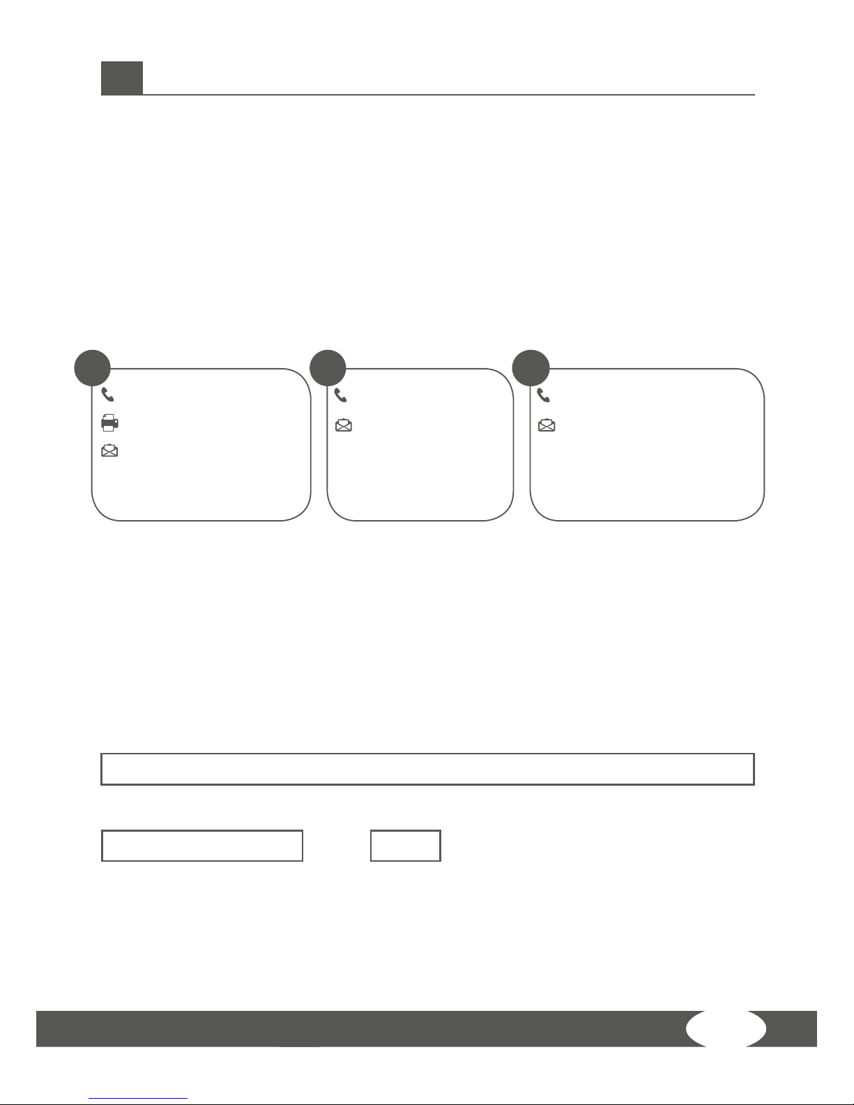
8.1 Service hotline
So that we can give you the best possible service, please have your model name, part
number, serial number, exploded drawing and parts list ready.
SERVICE-HOTLINE
8.2 Serial number and model name
Before assembling your equipment, nd the serial number on the white sticker and
enter it in the appropriate space.
Serial number:
Brand/category: Model name:
Taurus Multi-gym WS7
+31 172 619961
info@tshop.nl
Mon - Thu 9 am - 5 pm
Fri 9 am - 9 pm
Sat 10 am - 5 pm
NL
+44 141 876 3972
orders@powerhousetness.co.uk
Mon - Fri 9 am - 5 pm
UK
+49 4621 4210-0
+49 4621 4210-699
service@sport-tiedje.de
Mon - Fri 8:00 am - 6:00 pm
Sat 9:00 am - 6:00 pm
DE
Page 62

WS7
62
8.3 Parts list
No Description Dimensions Qty.
1 ground frame 1
2 guide bar Φ25*1853 2
3 back support tube Φ259*1757.5 2
4 outer hexagon bolt M10*65 6
5 shim
Φ10
74
6 outer hexagon bolt M10*20 8
7 weight stack rubber crash Φ60*Φ26*20 2
8 hexagon sock button head bolt M8*70 2
9 lock nut M8 6
10 weight stack lift bar 92 KG 1
11 below steel weight stack 6 KG 14
12 top steel weight stack 8 KG 1
14 shim Φ8 25
15 upper frame weldment 1
16 luck out M10 31
17 side support xing plate 2
18 sheild support frame 1
19 outer hexagon bolt M12*70 4
20 shim Φ12 22
21 lock nut M12 11
22 outer hexagon bolt M10*130 8
23 umbrella shape lock pin 2
24 plum ower pull pin M18*1.5 Φ10 2
25 inclined support frame 1
26 saet cushion adjust frame 1
27 leg curl bending tube 1
28 right decorative plate 1
29 left decorative plate 1
30 axis of rotation Φ17*57 1
31 outer hexagon bolt M12*75 4
32 outer hexagon bolt M12*130 3
Page 63

63
No Description Dimensions Qty.
33 seat cushion tube 1
34 buttery arm-right 1
35 buttery arm-left 1
36 front push frame holder 1
37 front push holder axle Φ17*134 1
38 outer hexagon bolt M8*16 9
39 front push arm 1
40 front push frame axle Φ17*100 1
41 labeling arc plate 1
42 pulley support frame 1
43 big shim Φ25*10*2.0 6
44 hexagon sock button head bolt M10*16 2
45 long semicircle plate 1
46 feet pad 1
47 outer hexagon bolt M10*70 1
48 “-” shape pulley frame 2
49 pulley Φ95*26 25
50 link sleeve Φ14*100 1
51 double pulley guide plate 1
52 spring shim Φ8 12
53 outer hexagon bolt M10*115 1
56 outer hexagon bolt M10*45 19
58 pulley spacer sleeve Φ22*Φ10.5*45.5 4
59 lat pull cable L:4540mm 1
60 9 hooks chain 3
61 long bar 1
62 outer hexagon bolt M8*45 4
63 hexagon sock button head bolt M10*45 1
64 low pull cable L:3365mm 1
65 short bar 1
66 double pulley plate 1
68 middle cable L:1500mm 1
69 buttery arm cable L:5375mm 1
Page 64

WS7
64
No Description Dimensions Qty.
70 7 hooks chain 2
71 hand pull belt 2
72 back cushion adjust frame 1
73 back cushion 1
74 outer hexagon bolt M8*40 4
75 seat cushion 1
76 sponge rod tube Φ25*480 1
77 sponge inner cap 6
78 sponge out cap 6
79 hexagon sock button head bolt M8*25 6
80 sponge Φ100*175 6
81 sheild 2
82 plum ower pull pin-M18*1.5 Φ12 1
83 outer hexagon bolt M10*25 3
84 spring shim Φ10 14
85 sponge pipe tube Φ25*450 1
86 magnetic pin Φ10*100 1
87 cushion Φ60*Φ26*42 2
Page 65

65
8.4 Exploded drawing
Page 66

WS7
66
CONTACT
Company head oce
Sport-Tiedje GmbH
Flensburger Str. 55
24837 Schleswig
Germany
GENERAL INFORMATION:
DE +49 4621 4210-0
info@sport-tiedje.com
NL +31 172 619961
info@tshop.nl
UK +44 141 876 3972
orders@powerhousetness.co.uk
DISCLAIMER
©2011 TAURUS is a registered brand of the company Sport-Tiedje
GmbH. All rights reserved. Any use of this trademark without the
explicit written permission of Sport-Tiedje is prohibited.
Product and manual are subject to change. Technical data can be changed without
advance notice.
Hotline for Technical Information
DE +49 4621 4210-0
+49 4621 4210-699
service@sport-tiedje.de
NL +31 172 619961
info@tshop.nl
UK +44 141 876 3986
support@powerhousetness.co.uk
www.sport-tiedje.com
www.taurus-tness.de
Please nd a detailed overview including address and opening hours for all specialist
tness stores of the Sport-Tiedje Group in Germany and abroad on the following
website.
www.sport-tiedje.com/en/stores
Page 67

67
Page 68

Multi-gym WS7
 Loading...