

Page 1
MANUALE D’USO E MANUTENZIONE
USE AND MAINTENANCE MANUAL
BEDIENUNGS - UND WARTUNGSANLEITUNG
MANUEL D’EMPLOI ET D’ENTRETIEN
MANUAL DE USO Y MANTENIMIENTO
ZIP
Automatismo per Cancelli a Battente - Uso Residenziale/Condominiale
Swing Gate Operator - Residential/Communities
Drehtorantrieb für Privat und Gewerbe
Automatisme pour Portails à Battant – Usage Résidentiel/Intensif
Accionador para Puertas Batientes – Uso Residencial/Comunidades
D_MNL0ZIP 11-12-2012 - Rev.15
IT - Istruzioni originali
Via Enrico Fermi, 43 - 36066 Sandrigo (VI) Italia
Tel +39 0444 750190 - Fax +39 0444 750376 - info@tauitalia.com - www.tauitalia.com
ZIP Series
1
Page 2

I - La Casa costruttrice si riserva il diritto di apportare modiche o miglioramenti al prodotto senza alcun preavviso. Eventuali
imprecisioni o errori riscontrabili nel presente fascicolo, saranno corretti nella prossima edizione.
All’apertura dell’imballo vericare che il prodotto sia integro. Riciclare i materiali secondo la normativa vigente.
L’installazione del prodotto dovrà essere effettuata da personale qualicato. La Ditta costruttrice Tau declina ogni
responsabilità per danni derivanti a cose e/o persone dovuti ad un’eventuale errata installazione dell’impianto o la non
messa a Norma dello stesso secondo le vigenti Leggi (vedi Direttiva Macchine).
GB - The manufacturer reserves the right to modify or improve products without prior notice. Any inaccuracies or errors found in this
handbook will be corrected in the next edition.
When opening the packing please check that the product is intact. Please recycle materials in compliance with current
regulations.
This product may only be installed by a qualied tter. The manufacturer declines all liability for damage to property
and/or personal injury deriving from the incorrect installation of the system or its non-compliance with current law (see
Machinery Directive).
D - Der Hersteller behält sich das Recht vor, ohne vorherige Benachrichtung Änderungen oder Verbesserungen am Produkt
anzubringen. Ungenauigkeiten oder Fehler, die in der vorliegenden Ausgabe festgestellt werden, werden in der nächsten
Ausgabe berichtigt.
Beim Öffnen der Verpackung prüfen, dass das Produkt keine Schäden aufweist. Die Materialien nach den gültigen Vorschriften
recyclen.
Die Installation des Produktes muss von Fachpersonal ausgeführt werden. Die Herstellerrma TAU übernimmt keinerlei
Haftung für Personen- und/oder Sachschäden aufgrund einer falschen Installation der Anlage oder der Nichtkonformität
derselben mit den gültigen Gesetzen (siehe Maschinenrichtlinie).
F - Le Constructeur se réserve le droit d’apporter des modications ou des améliorations au produit sans aucun préavis. Les
éventuelles imprécisions ou erreurs présentes dans ce fascicule seront corrigées dans la prochaine édition.
À l’ouverture de l’emballage, vérier que le produit est intact. Recycler les matériaux suivant les normes en vigueur.
L’installation du produit devra être effectuée par du personnel qualié. Tau décline toute responsabilité pour les
dommages aux choses et/ou personnes dus à une éventuelle installation erronée de l’automatisme ou à la non-mise
aux normes suivant les lois en vigueur (voir Directive Machines).
E - El Fabricante se reserva el derecho de modicar o actualizar el producto sin aviso previo. Posibles imprecisiones o errores en
este manual serán corregidos en la próxima edición.
Cuando abra el embalaje, controle que el producto esté íntegro. Recicle los materiales según la normativa vigente.
La instalación del producto tiene que ser efectuada por personal cualicado. El Fabricante Tau no se asume ninguna
responsabilidad por lesiones a personas o averías a cosas causadas por una instalación incorrecta del equipo o la por
la inobservancia de la normativa vigente (véase Directiva de Máquinas).
2
ZIP Series
Page 3

AVVERTENZE PER L’INSTALLATORE
Italiano
OBBLIGHI GENERALI PER LA SICUREZZA
A) Leggere attentamente le istruzioni prima di procedere all’installazione, in quanto forniscono importanti indicazioni concernenti la
sicurezza, l’installazione, l’uso e la manutenzione. Una errata installazione o un errato uso del prodotto può portare a gravi danni alle
persone.
B) I materiali dell’imballaggio (plastica, polistirolo, ecc.) non devono essere lasciati alla portata dei bambini in quanto potenziali fonti di pericolo.
C) Conservare le istruzioni per riferimenti futuri.
D) Questo prodotto è stato progettato e costruito esclusivamente per l’utilizzo indicato in questa documentazione. Qualsiasi altro utilizzo non
espressamente indicato potrebbe pregiudicare l’integrità del prodotto e/o rappresentare fonte di pericolo.
E) TAU declina qualsiasi responsabilità derivata dall’uso improprio o diverso da quello per cui l’automatismo è destinato.
F) Non installare il prodotto in ambiente e atmosfera esplosivi.
G) Gli elementi costruttivi meccanici devono essere in accordo con quanto stabilito dalle Norme EN 12604 e EN 12605. Per i Paesi extra-CEE, oltre
ai riferimenti normativi nazionali, per ottenere un livello di sicurezza adeguato, devono essere seguite le Norme sopra riportate.
H) TAU non è responsabile dell’inosservanza della Buona Tecnica nella costruzione delle chiusure da motorizzare, nonché delle deformazioni che
dovessero intervenire nell’utilizzo.
I) L’installazione deve essere effettuata nell’osservanza delle Norme EN 12453 e EN 12445. Il livello di sicurezza dell’automazione deve essere
C+D.
J) Prima di effettuare qualsiasi intervento sull’impianto, togliere l’alimentazione elettrica e scollegare le batterie.
K) Prevedere sulla rete di alimentazione dell’automazione un interruttore onnipolare con distanza d’apertura dei contatti uguale o superiore a 3 mm.
È consigliabile l’uso di un magnetotermico da 6A con interruzione onnipolare.
L) Vericare che a monte dell’impianto vi sia un interruttore differenziale con soglia da 0,03 A.
M) Vericare che l’impianto di terra sia realizzato a regola d’arte e collegarvi le parti metalliche della chiusura.
N) L’automazione dispone di una sicurezza intrinseca antischiacciamento costituita da un controllo di coppia. E’ comunque necessario vericarne
la soglia di intervento secondo quanto previsto dalle Norme indicate al punto I.
O) I dispositivi di sicurezza (norma EN 12978) permettono di proteggere eventuali aree di pericolo da Rischi meccanici di movimento, come ad Es.
schiacciamento, convogliamento, cesoiamento.
P) Per ogni impianto è consigliato l’utilizzo di almeno una segnalazione luminosa nonché di un cartello di segnalazione ssato adeguatamente sulla
struttura dell’insso, oltre ai dispositivi citati al punto O.
Q) Il costruttore dell’automazione declina ogni responsabilità qualora vengano installati componenti incompatibili ai ni della sicurezza e del buon
funzionamento. Per l’eventuale riparazione o sostituzione dei prodotti dovranno essere utilizzati esclusivamente ricambi originali.
R) Per la manutenzione utilizzare esclusivamente parti originali TAU.
S) Non eseguire alcuna modica sui componenti facenti parte del sistema d’automazione.
T) L’installatore deve fornire tutte le informazioni relative al funzionamento manuale del sistema in caso di emergenza e consegnare all’Utente
utilizzatore dell’impianto la “Guida Utente” allegata al prodotto.
U) Non permettere ai bambini o persone di sostare nelle vicinanze del prodotto durante il funzionamento.
W) Tenere fuori dalla portata dei bambini radiocomandi o qualsiasi altro datore di impulso, per evitare che l’automazione possa essere azionata
involontariamente.
X) Il transito tra le ante deve avvenire solo a cancello completamente aperto.
Y) L’Utente utilizzatore deve astenersi da qualsiasi tentativo di riparazione o d’intervento diretto e rivolgersi solo a personale qualicato.
Z) Tutto quello che non è previsto espressamente in queste istruzioni non è permesso.
Consigliamo di riporre tutta la documentazione relativa all’impianto all’interno o nelle immediate vicinanze della centralina.
IMPORTANT NOTICE FOR THE INSTALLER
English
GENERAL SAFETY REGULATIONS
A) Please read these instructions carefully before installing the product as they contain important information concerning safety,
installation, use and maintenance. Incorrect installation or incorrect use of the product could cause serious harm to people.
B) Do not leave packing materials (plastic, polystyrene, etc.) within reach of children as such materials are potential sources of danger.
C) Store these instructions for future reference.
D) This product was designed and built strictly for the use indicated in this documentation. Any other use, not expressly indicated here, could
compromise the good condition/operation of the product and/or be a source of danger.
E) TAU declines all liability caused by improper use or use other than that for which the automated system was intended.
F) Do not install the product in explosive environments.
G) The mechanical parts must conform to the provisions of Standards EN 12604 and EN 12605. For non-EU countries, to obtain an adequate level
of safety, the Standards mentioned above must be observed, in addition to national legal regulations.
H) TAU is not responsible for failure to observe Good Technique in the construction of the closing elements to be motorised, or for any deformation
that may occur during use.
I) The installation must conform to Standards EN 12453 and EN 12445. The safety level of the automated system must be C+D.
J) Before attempting any job on the system, cut out electrical power and disconnect the batteries.
K) The mains power supply of the automated system must be tted with an all-pole switch with contact opening distance of 3mm or greater. Use of
a 6A thermal breaker with all-pole circuit break is recommended.
L) Make sure that a differential switch with threshold of 0.03 A is tted upstream of the system.
M) Make sure that the earthing system is perfectly constructed, and connect metal parts of the means of the closure to it.
N) The automated system is supplied with an intrinsic anti-crushing safety device consisting of a torque control. Nevertheless, its tripping threshold
must be checked as specied in the Standards indicated at point “I”.
O) The safety devices (EN 12978 standard) protect any danger areas against mechanical movement Risks, such as crushing, dragging, and
shearing.
P) Use of at least one indicator-light is recommended for every system, as well as a warning sign adequately secured to the frame structure, in
addition to the devices mentioned at point “O”.
Q) The manufacturer declines all liability if incompatible safety and components are installed. Only use original spare parts to repair or replace the
product.
R) For maintenance, strictly use original parts by TAU.
S) Do not in any way modify the components of the automated system.
T) The installer shall supply all information concerning manual operation of the system in case of an emergency, and shall hand over to the user
the “User Guide” supplied with the product.
U) Do not allow children or adults to stay near the product while it is operating.
W) Keep remote controls or other pulse generators away from children, to prevent the automated system from being activated involuntarily.
X) Transit through the leaves is allowed only when the gate is fully open.
Y) The user must not attempt any kind of repair or direct action whatever and contact qualied personnel only.
Z) Anything not expressly specied in these instructions is not permitted.
Keep all the documents concerning the system inside or near the central control unit.
ZIP Series
3
Page 4

HINWEISE FÜR DEN INSTALLATIONSTECHNIKER
Deutsch
ALLGEMEINE SICHERHEITSVORSCHRIFTEN
A) Die Anweisungen vor der Installation genau lesen, da sie wichtige Hinweise mit Bezug auf Sicherheit, Installation, Bedienung und Wartung liefern.
Eine falsche Installation oder ein fehlerhafter Betrieb des Produktes können zu schwerwiegenden Personenschäden führen.
B) Das Verpackungsmaterial (Kunststoff, Styropor, usw.) sollte nicht in Reichweite von Kindern aufbewahrt werden, da es eine potentielle Gefahrenquelle darstellt.
C) Die Anleitung sollte aufbewahrt werden, um auch in Zukunft Bezug auf sie nehmen zu können.
D) Dieses Produkt wurde ausschließlich für den in diesen Unterlagen angegebenen Gebrauch entwickelt und hergestellt. Jeder andere Gebrauch, der nicht
ausdrücklich angegeben ist, könnte die Unversehrtheit des Produktes beeinträchtigen und/oder eine Gefahrenquelle darstellen.
E) Die Firma TAU lehnt jede Haftung für Schäden, die durch unsachgemäßen oder nicht bestimmungsgemäßen Gebrauch der Automatik verursacht werden, ab.
F) Das Produkt nicht in EX-Umgebung bzw. EX-Atmosphäre installieren.
G) Die mechanischen Bauelemente müssen den Anforderungen der Normen EN 12604 und EN 12605 entsprechen. Für Länder, die nicht der Europäischen Union
angehören, sind für die Gewährleistung eines entsprechenden Sicherheitsniveaus neben den nationalen gesetzlichen Bezugsvorschriften die oben aufgeführten
Normen zu beachten.
H) Die Firma TAU übernimmt keine Haftung im Falle von nicht fachgerechten Ausführungen bei der Herstellung der anzutreibenden Schließvorrichtungen sowie bei
Deformationen, die eventuell beim Betrieb entstehen.
I) Die Installation muß unter Beachtung der Normen EN 12453 und EN 12445 erfolgen. Die Sicherheitsstufe der Automatik sollte C+D sein.
J) Vor der Ausführung jeglicher Eingriffe auf der Anlage sind die elektrische Versorgung und die Batterie abzunehmen.
K) Auf dem Versorgungsnetz der Automatik ist ein omnipolarer Schalter mit Öffnungsabstand der Kontakte von über oder gleich 3 mm einzubauen. Darüber hinaus
wird der Einsatz eines Magnetschutzschalters mit 6A mit omnipolarer Abschaltung empfohlen.
L) Es sollte überprüft werden, ob vor der Anlage ein Differentialschalter mit einer Auslöseschwelle von 0,03 A zwischengeschaltet ist.
M)
Es sollte überprüft werden, ob die Erdungsanlage fachgerecht ausgeführt wurde. Die Metallteile der Schließung sollten an diese Anlage angeschlossen werden.
N) Die Automation verfügt über eine eingebaute Sicherheitsvorrichtung für den Quetschschutz, die aus einer Drehmomentkontrolle besteht. Es ist in jedem Falle
erforderlich, deren Eingriffsschwelle gemäß der Vorgaben der unter Punkt “I” angegebenen Vorschriften zu überprüfen.
O) Die Sicherheitsvorrichtungen (Norm EN 12978) ermöglichen den Schutz eventueller Gefahrenbereiche vor mechanischen Bewegungsrisiken, wie zum Beispiel
Quetschungen, Mitschleifen oder Schnittverletzungen.
P) Für jede Anlage wird der Einsatz von mindestens einem Leuchtsignal empfohlen sowie eines Hinweisschildes, das über eine entsprechende Befestigung mit
dem Aufbau des Tors verbunden wird. Darüber hinaus sind die unter Punkt ”O” erwähnten Vorrichtungen einzusetzen.
Q) Der Hersteller der Automatisierung übernimmt keinerlei Haftung, falls Bestandteile installiert werden, die – was Sicherheit und korrekten Betrieb betrifft – nicht
kompatibel sind. Zur Reparatur oder zum Ersatz der Produkte dürfen ausschließlich Originalersatzteile verwendet werden.
R) Bei der Instandhaltung sollten ausschließlich Originalteile der Firma TAU verwendet werden.
S) Auf den Komponenten, die Teil des Automationssystems sind, sollten keine Veränderungen vorgenommen werden.
T) Der Installateur sollte alle Informationen hinsichtlich des manuellen Betriebs des Systems in Notfällen liefern und dem Betreiber der Anlage das “Führer
Benutzer”, das dem Produkt beigelegt ist, übergeben.
U) Weder Kinder noch Erwachsene sollten sich während des Betriebs in der unmittelbaren Nähe der Automation aufhalten.
W) Die Funksteuerungen und alle anderen Impulsgeber sollten außerhalb der Reichweite von Kindern aufbewahrt werden, um ein versehentliches Aktivieren der
Automation zu vermeiden.
X) Der Durchgang oder die Durchfahrt zwischen den Flügeln darf lediglich bei vollständig geöffnetem Tor erfolgen.
Y)
Der Betreiber sollte keinerlei Reparaturen oder direkte Eingriffe auf der Automation ausführen, sondern sich hierfür ausschließlich an qualiziertes Fachpersonal wenden.
Z) Alle Vorgehensweisen, die nicht ausdrücklich in der vorliegenden Anleitung vorgesehen sind, sind nicht zulässig
Wir empfehlen, alle Unterlagen der Anlage in der Steuerzentrale oder in ihrer unmittelbaren Nähe aufzubewahren.
CONSIGNES POUR L’INSTALLATEUR
Français
RÈGLES DE SÉCURITÉ
A) Lire attentivement les instructions avant de procéder à l’installation, dans la mesure où elles fournissent des indications importantes concernant la
sécurité, l’installation, l’emploi et la maintenance. Une installation erronée ou un usage erroné du produit peut entraîner de graves conséquences
pour les personnes.
B) Les matériaux d’emballage (matière plastique, polystyrène, etc.) ne doivent pas être laissés à la portée des enfants car ils constituent des sources potentielles
de danger.
C) Conserver les instructions pour les références futures.
D) Ce produit a été conçu et construit exclusivement pour l’usage indiqué dans cette documentation. Toute autre utilisation non expressément indiquée pourrait
compromettre l’intégrité du produit et/ou représenter une source de danger.
E) TAU décline toute responsabilité qui dériverait d’usage impropre ou différent de celui auquel l’automatisme est destiné.
F) Ne pas installer le produit dans un environnement et une atmosphère explosifs.
G) Les composants mécaniques doivent répondre aux prescriptions des Normes EN 12604 et EN 12605. Pour les Pays extra-CEE, l’obtention d’un niveau de
sécurité approprié exige non seulement le respect des normes nationales, mais également le respect des Normes susmentionnées.
H) TAU n’est pas responsable du non-respect de la Bonne Technique dans la construction des fermetures à motoriser, ni des déformations qui pourraient intervenir
lors de l’utilisation.
I) L’installation doit être effectuée conformément aux Normes EN 12453 et EN 12445. Le niveau de sécurité de l’automatisme doit être C+D.
J) Couper l’alimentation électrique et déconnecter la batterie avant toute intervention sur l’installation.
K) Prévoir, sur le secteur d’alimentation de l’automatisme, un interrupteur omnipolaire avec une distance d’ouverture des contacts égale ou supérieure à 3 mm. On
recommande d’utiliser un magnétothermique de 6A avec interruption omnipolaire.
L) Vérier qu’il y ait, en amont de l’installation, un interrupteur différentiel avec un seuil de 0,03 A.
M) Vérier que la mise à terre est réalisée selon les règles de l’art et y connecter les pièces métalliques de la fermeture.
N) L’automatisme dispose d’une sécurité intrinsèque anti-écrasement, formée d’un contrôle du couple. Il est toutefois nécessaire d’en vérier le seuil d’intervention
suivant les prescriptions des Normes indiquées au point “I”.
O) Les dispositifs de sécurité (norme EN 12978) permettent de protéger des zones éventuellement dangereuses contre les Risques mécaniques du mouvement,
comme l’écrasement, l’acheminement, le cisaillement.
P) On recommande que toute installation soit doté au moins d’une signalisation lumineuse, d’un panneau de signalisation xé, de manière appropriée, sur la
structure de la fermeture, ainsi que des dispositifs cités au point “O”.
Q) Le constructeur de l’automatisme décline toute responsabilité en cas d’installation de composants incompatibles en matière de sécurité et de bon fonctionnement.
Pour toute réparation ou pour tout remplacement des produits, il faudra utiliser exclusivement des pièces de rechange originales.
R) Utiliser exclusivement, pour l’entretien, des pièces TAU originales.
S) Ne jamais modier les composants faisant partie du système d’automatisme.
T) L’installateur doit fournir toutes les informations relatives au fonctionnement manuel du système en cas d’urgence et remettre à l’Usager qui utilise l’installation
le “Guide Usager” fournie avec le produit.
U) Interdire aux enfants ou aux tiers de stationner près du produit durant le fonctionnement.
W) Eloigner de la portée des enfants les radiocommandes ou tout autre générateur d’impulsions, pour éviter tout actionnement involontaire de l’automatisme.
X) Le transit entre les vantaux ne doit avoir lieu que lorsque le portail est complètement ouvert.
Y) L’Usager qui utilise l’installation doit éviter toute tentative de réparation ou d’intervention directe et s’adresser uniquement à un personnel qualié.
Z) Tout ce qui n’est pas prévu expressément dans ces instructions est interdit.
Nous conseillons de conserver toute la documentation relative à l’installation à l’intérieur de l’armoire de commande ou à proximité immédiate.
4
ZIP Series
Page 5

ADVERTENCIAS PARA EL INSTALADOR
Español
REGLAS GENERALES PARA LA SEGURIDAD
A) Lea con atención las instrucciones antes de proceder con la instalación, puesto que suministran importantes indicaciones sobre la
seguridad, instalación, uso y mantenimiento. Una instalación incorrecta o un uso impropio del producto puede causar graves daños
a las personas.
B) Los materiales del embalaje (plástico, poliestireno, etc.) no deben dejarse al alcance de los niños, ya que constituyen fuentes potenciales de
peligro.
C) Guarden las instrucciones para futuras consultas.
D) Este producto ha sido proyectado y fabricado exclusivamente para la utilización indicada en el presente manual. Cualquier uso diverso del
previsto podría perjudicar el funcionamiento del producto y/o representar fuente de peligro.
E) TAU declina cualquier responsabilidad derivada de un uso impropio o diverso del previsto.
F) No instale el producto en locales con atmósfera explosiva.
G) Los elementos constructivos mecánicos deben estar de acuerdo con lo establecido en las Normas EN 12604 y EN 12605. Para los países no
pertenecientes a la CEE, además de las referencias normativas nacionales, para obtener un nivel de seguridad adecuado, deben seguirse las
Normas arriba indicadas.
H) TAU no es responsable del incumplimiento de las buenas técnicas de fabricación de los cierres que se han de motorizar, así como de las
deformaciones que pudieran intervenir en la utilización.
I)
La instalación debe ser realizada de conformidad con las Normas EN 12453 y EN 12445. El nivel de seguridad de la automación debe ser C+D.
J) Quiten la alimentación eléctrica y desconecten las baterías antes de efectuar cualquier intervención en la instalación.
K) Coloquen en la red de alimentación de la automación un interruptor omnipolar con distancia de apertura de los contactos igual o superior a 3
mm. Se aconseja usar un magnetotérmico de 6A con interrupción omnipolar.
L) Comprueben que la instalación disponga línea arriba de un interruptor diferencial con umbral de 0,03 A.
M) Veriquen que la instalación de tierra esté correctamente realizada y conecten las partes metálicas del cierre.
N) La automación dispone de un dispositivo de seguridad antiaplastamiento constituido por un control de par. No obstante, es necesario comprobar
el umbral de intervención según lo previsto en las Normas indicadas en el punto “I”.
O) Los dispositivos de seguridad (norma EN 12978) permiten proteger posibles áreas de peligro de Riesgos mecánicos de movimiento, como por
ej. aplastamiento, arrastre, corte.
P) Para cada equipo se aconseja usar por lo menos una señalización luminosa así como un cartel de señalización adecuadamente jado a la
estructura del bastidor, además de los dispositivos indicados en el “O”.
Q) El fabricante de la automatización no se asume ninguna responsabilidad si se instalan componentes incompatibles para la seguridad y el
funcionamiento correcto. Para una posible reparación o sustitución de los productos, use sólo recambios originales.
R) Para el mantenimiento utilicen exclusivamente piezas originales TAU.
S) No efectúen ninguna modicación en los componentes que forman parte del sistema de automación.
T) El instalador debe proporcionar todas las informaciones relativas al funcionamiento del sistema en caso de emergencia y entregar al usuario del
equipo la “Guía Usuario” que se adjunta al producto.
U) No permitan que niños o personas se detengan en proximidad del producto durante su funcionamiento.
W) Mantengan lejos del alcance los niños los telemandos o cualquier otro emisor de impulso, para evitar que la automación pueda ser accionada
involuntariamente.
X) Sólo puede transitarse entre las hojas si la cancela está completamente abierta.
Y) El usuario no debe por ningún motivo intentar reparar o modicar el producto, debe siempre dirigirse a personal cualicado.
Z) Todo lo que no esté previsto expresamente en las presentes instrucciones debe entenderse como no permitido.
Se aconseja guardar toda la documentación de la instalación en el interior o cerca de la central.
INDICE - INHALTSVERZEICHNIS - CONTENTS - INDEX – ÍNDICE
pag. 6 Caratteristiche tecniche della serie ZIP - Technical features of the ZIP series - Technische Eigenschaften der serie ZIP -
Caractéristiques techinques de la série ZIP - Características técnicas de la serie ZIP.
pag. 7 Italiano
pag. 10 English
pag. 13 Disegni - Drawings - Zeichnen - Projets - Dibujos
pag. 17 Deutsch
pag. 20 Français
pag. 23 Español
pag. 27 Garanzia - Garantie - Guarantee - Garantie - Garantía
ZIP Series
5
Page 6
CARATTERISTICHE TECNICHE DELLA SERIE ZIP / TECHNICAL FEATURES OF THE ZIP SERIES / TECHNISCHE
EIGENSCHAFTEN DER SERIE ZIP / CARACTÉRISTIQUES TECHNIQUES DE LA SERIE ZIP / CARACTERÍSTICAS
TÉCNICAS DE LA SERIE ZIP
I motoriduttori della serie zip sono stati progettati per installazione esterna. Si fa espresso diveto di utilizzare l’apparecchio per
scopi diversi o in circostanze diverse da quelle menzionate.
Gearmotors of the zip series have been designed to external installation. It is categorically forbidden to use the equipment for
any other use or under circumstances different from those mentionedherein.
Die Toröffner der serie ZIP wurden für Außeneinbau Konstruiert. Es ist ausdrücklich Verboten, das Gerät zu anderen Zwecken
oder unter anderen Umständen als Erwähnt zu Verwenden.
Les motoréducteurs de la série zip ont été projetés pour installation extérieur. Il est formellement interdit d ’utiliser l’appareil
pour d ’autres emplois ou dans des circonstances différentes de celles qui sont mentionnées dans ce manuel.
Los motorreductores de la serie zip han sido pensados para instalación exterior. Se advierte que está totalmente prohibido
usar el aparato para objetivos diversos o en circunstancias diferentes a las mencionadas.
ZIP12 ZIP
Alimentazione / Voltage input / Stromversorgung / Alimentation / Alimentación 230 V AC ±10% 50/60 Hz
Alimentazione Motore / Voltage input to motor / Motorversorgung
Alimentation Moteur / Motor
Corrente assorbita (a vuoto) / Absorbed current ( no load) / Aufgenommene Strom (leer)
Courant absorbé (à vide) / Corriente absorbida (en vacÍo)
Potenza assorbita (a vuoto) / Absorbed power (no load) / Aufgenommene Leistung (leer)
Puissance absorbé (à vide) / Potencia absorbida (en vacío)
Intervento di termoprotezione / Thermal protection trips at / Ansprechen des Wärmeschutzes
Intervention protection thermique / Desconexión protección térmica
Tempo di apertura 90° / Opening time 90° / Laufzeit, 90°
Temps de ouverture 90° / Tiempo de apertura 90°
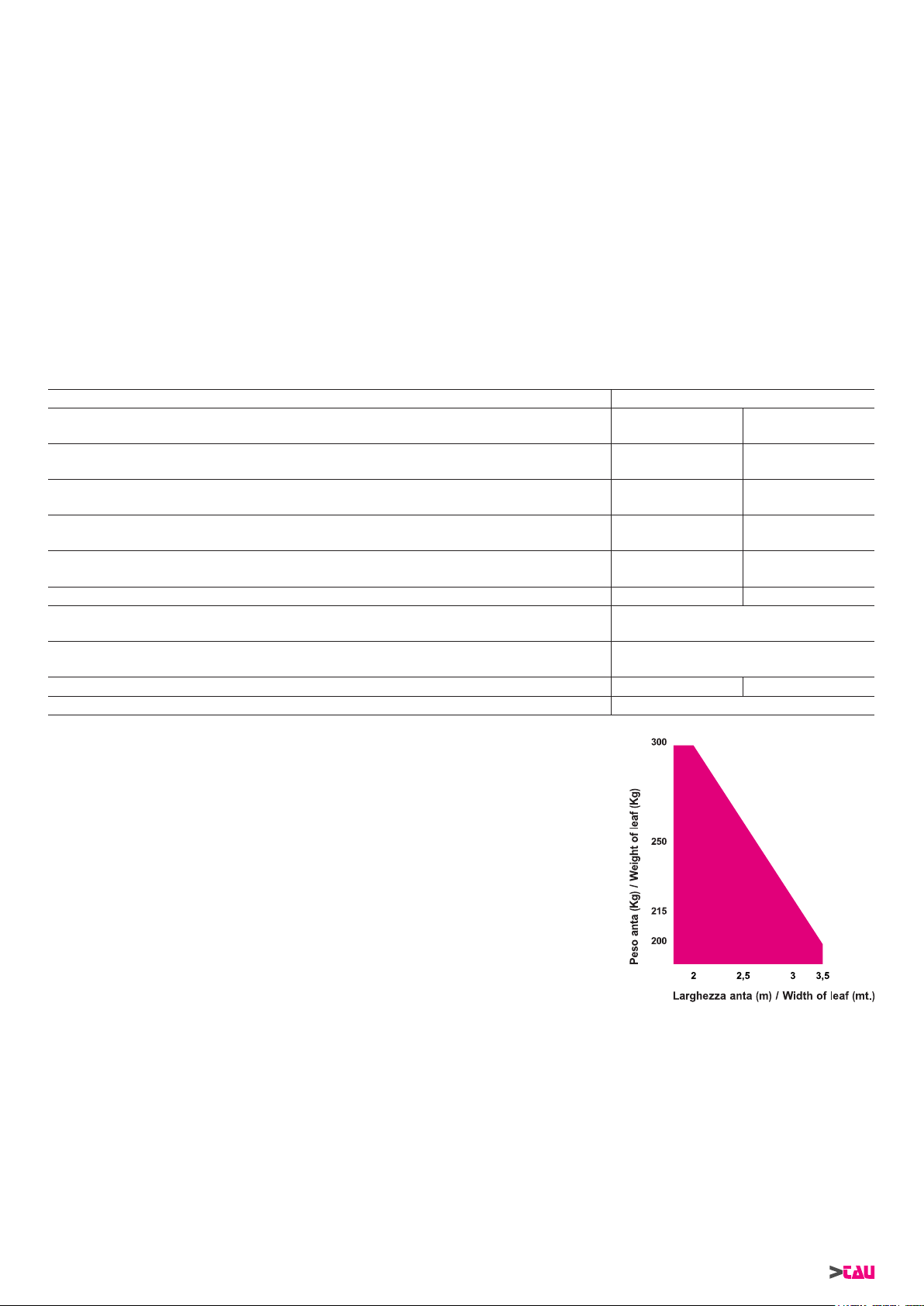
Coppia max. / Max. torque / Max. Drehmoment / Couple max. / Par máx. 416 Nm 334 Nm
Lunghezza max anta / Max length of leaf / Max. Flügellänge
Longueur max. battant / Longitud máx. hoja
Temperatura di esercizio / Operating temperature / Betriebstemperatur
Température de fonctionnement / Temperatura de servicio
Peso / Weight / Gewicht / Poids / Peso 10 Kg 8,5 Kg
IP Motore / Motor IP / Schutzart des Motor (IP) / IP Moteur / IP Motor IP 44
18V DC ±10% 230 V AC ±10%
0,8 A 1 A
15 W 190 W
- 150 °C (autoreset)
8 s 13 s
3,5 m
Da –20 °C a +55 °C
Nota: in presenza di cancelli ad ante battenti cieche, prevedere l’installazione di
un’elettroserratura sia per la tenuta in chiusura che per la salvaguardia del
prodotto.
Note: in case of closed design gate leaves an electro lock must be installed to avoid
major damages.
Anmerkung: Bei Toren mit kompletter- bzw. teilächiger Füllung ist ein Elektro-
schloss erforderlich.
Note: en présence de portails à vantaux pleins, nous recommandons de prévoir
l’installation d’une serrure électrique, soit pour garder la fermeture bien serrée
soit pour la protection du produit.
Nota: Con hojas totalmente ciegas instalar un electro-cierre para evitar daños al ac-
cionador.
Nota: quando il sistema in 12 vdc è alimentato unicamente dalla batteria (in caso di black-out oppure in abbinamento con
pannello fotovoltaico), le prestazioni espresse dal motoriduttore (forza e velocità) si riducono del 30% ca.
Note: When the system is in the 12 v dc mode and is powered by the battery only (in the event of a power failure or when
used in conjunction with a photovoltaic panel), the gear motor’s output (power and speed) is reduced by approximately 30% .
Anmerkung: Wenn das 12 V DC System nur über Batterie gespeist ist (bei Stromausfall oder in Kombination mit einem Photovoltaicpaneel), verringern sich die leistungen des Getriebemotors (Kraft und Geschwindigkeit) um ca. 30%.
Attention : quand le système à 12 vcc est alimenté uniquement par la batterie (en cas de coupure de courant ou bien en association avec un panneau photovoltaïque), les performances du motoréducteur (force et vitesse) diminuent d’environ 30% .
Nota: cuando el sistema de 12 vdc es alimentado únicamente por la batería (en caso de corte de corriente, o bien combinado
con panel fotovoltaico), las prestaciones del motorreductor (fuerza y velocidad) se reducen en un 30%.
6
ZIP Series
Page 7
MATERIALI PER L ’INSTALLAZIONE (g. 2)
1_ COD P-650ZIP motoriduttore ZIP
2_ COD P-150BAR braccio articolato + piastra
3_ COD S-150BAR0020 asta con borchia per braccio
articolato
4_ COD S-150BAR0030 asta con fori per braccio arti-
colato
5_ COD S-650RBS0030 staffa attacco
6_ COD M-V350AM12A0 dado E autobloccante M12
alto
7_ COD M-V100012035I vite TE M12x35 inox
8_ COD M-V500012036I rosetta piana D.12x36 inox
9_ COD M-V500008024I rosetta piana D.8x24 inox
10_ COD M-V100008016I vite TE M8x16 inox
PRESENTAZIONE DELL’ AUTOMATISMO
Occorre distinguere tra due tipi di motorizzazioni:
1 - motore reversibile = l’automatismo non è dotato di
sblocco
2 - motore non reversibile = l’automatismo è dotato di
sblocco
Di conseguenza si consiglia di installare l’elettroserratura in due
casi:
1° il motore è di tipo reversibile e la lunghezza dell’anta eccede
1,6 metri
2° indipendentemente dal tipo di motore se l’anta è molto lunga
ed è quindi soggetta ad oscillazioni in apertura ed in chiusura.
Il motoriduttore ZIP può essere fornito, a richiesta, con necorsa
elettrici interni al motore.
CONSIDERAZIONI PRELIMINARI ALL’ INSTALLAZIONE
Il sistema da voi scelto risolve brillantemente ogni problema di installazione nei più comuni casi di automazione domestica e residenziale.
Si ritiene utile tuttavia fornire i seguenti suggerimenti
1. Installare il motoriduttore il più vicino possibile all’anta da auto-
matizzare e comunque dove non crei intralcio all’apertura
2. Poiché la lunghezza del braccio articolato determina la posizio-
ne di ssaggio della staffa di aggancio all’anta, si consiglia di :
- tenere la lunghezza del tratto di braccio collegato al motore
di due-tre centimetri superiore al suo minimo.
- tenere la lunghezza del tratto di braccio collegato all’anta di
qualche centimetro inferiore al suo massimo.
3. Prima di ssare anche la staffa. provare a muovere manualmente l’anta (con il motoriduttore sbloccato) e vericare se
l’automazio-ne è in grado di aprire dall’angolo da voi desiderato.
Nota: per una completa sicurezza si fa obbligo di installare, se
non presenti, i fermi meccanici (battenti a pavimento) con tappo in gomma in apertura e in chiusura, come mostrato nella
g. 13 e nella g. 14.
FISSAGGIO PIASTRA DI ANCORAGGIO (g. 3)
Per il ssaggio usare tasselli ad espansioni (con pilastro in muratura) oppure forare e lettare (se la piastra viene unita ad una
struttura metallica).
FISSAGGIO STAFFA DI AGGANCIO ALL’ANTA (g. 4)
Usare viti autolettanti per ssare la staffetta dove determinato in
accordo con le “Considerazioni preliminari all’installazione“.
ANCORAGGIO ED INSTALLAZIONE MOTORIDUTTORE
Il braccio è di tipo articolato, quindi è necessario in fase di installazione determinare la corretta posizione in modo che l’ asta con
fori e l’asta con borchia formino un angolo < 170° quando le due
ante sono chiuse.
Per comprendere meglio il signicato vedere la g. 5 e la g. 6.
Sbloccare il motoriduttore per facilitare le operazioni.
Dopo avere ssato la piastra di ancoraggio e la staffa di attacco,
procedere in questo modo:
1_ ancorare il motoriduttore alla piastra usando 4 viti TE M6x120,
4 rondelle Ø6x12x1.2 e 4 dadi M6 alti autobloccanti come evidenziato nel disegno;
2_ per il ssaggio sfruttare i 4 fori passanti ricavati sulla carcassa
in alluminio del motoriduttore; collocare la rondella tra dado e
motore;
ZIP Series
3_ ssare l’asta con borchia all’albero di uscita motore avvitando
un bullone; assicurarsi che l’asta sia ben saldamente bloccata
e che non possa staccarsi inavvertitamente durante l’uso;
4_ ssare con apposita vite + dado l’asta con fori alla staffa ssata
all’anta del cancello;
5_ dopo avere passato i cavi per i collegamenti elettrici, sfruttando
i fori ricavati sulla piastra, inlare il carter e ssarlo con 2 viti
TCEI M6x40 come illustrato in g. 7 ed in g. 8.
SBLOCCO MANUALE (g. 9 - g. 10)
Nota: non forzare la rotazione della chiave a brugola (A g. 10),
ma accertarsi dell’avvenuto sblocco agendo contemporaneamente anche sull’anta del cancello.
COLLEGAMENTO ELETTRICO AL MOTORE
• Collegarsi sfruttando il foro libero sulla piastra di ancoraggio.
• Proteggere i cavi con una guaina essibile.
• Usare cavi della sezione minima di 1,5 mm².
• Invertendo i collegamenti, il motore inverte il senso di rotazione.
Posizionare la centrale di comando (se esterna) nelle immediate vicinanze dei motori.
Evitare che i cavi dei dispositivi ausiliari siano posizionati all’interno di condutture dove sono presenti
altri cavi che alimentano grossi carichi o lampade
con starter elettronico.
Nel caso in cui vengano installati pulsanti di comando o spie di segnalazione, all’interno di abitazioni o
di edici che distano parecchi metri dalla centrale
stessa, è consigliabile disaccoppiare il segnale tramite relay, onde evitare disturbi indotti.
RACCOMANDAZIONI DI CARATTERE GENERALE
- Integrare la sicurezza del cancello conformemente alla normativa vigente.
- Scegliere percorsi brevi per i cavi e tenere separati i cavi di
potenza dai cavi di comando.
- Installare la scheda comando entro una scatola a tenuta stagna o con grado di protezione IP45.
- Effettuare una corretta messa a terra dell’apparecchio.
- Per la messa a punto della coppia massima del motoriduttore,
attenersi alle normative in vigore.
- In accordo con la normativa europea in materia di sicurezza si
consiglia di inserire un interruttore esterno per poter togliere
l’alimentazione in caso di manutenzione del cancello.
- Vericare che ogni singolo dispositivo sia efciente ed efcace.
- Afggere cartelli facilmente leggibili che informino della presenza del cancello motorizzato.
- Quantunque il motoriduttore possa essere dotato di tutti i dispositivi di sicurezza si consiglia caldamente di tenere fuori
della portata di bambini o di persone inabili ogni dispositivo in
grado di comandare l’apertura del cancello e che possa inavvertitamente essere usato senza sorveglianza.
USO
Il motoriduttore ZIP è stato progettato per movimentare cancelli
ad anta battente ad asse verticale con ante della lunghezza non
superiore a 3500 mm.
Si fa espresso divieto di utilizzare l’apparecchio per scopi diversi o
in circostanze diverse da quelle menzionate.
Normalmente la centralina elettronica installata consente di selezionare il funzionamento:
Automatico: un impulso di comando esegue l’apertura
e la chiusura del cancello
Semiautomatico: un impulso di comando esegue l’apertura
o la chiusura del cancello
In caso di gestione manuale agire prima sul dispositivo di sblocco.
Si ricorda che siamo in presenza di un dispositivo automatico e
alimentato a corrente, perciò da usare con precauzione.
In particolare, si ammonisce di:
• non toccare l’apparecchio con mani bagnate e/o piedi bagnati
o nudi;
7
ITALIANO
Page 8

• togliere la corrente prima di aprire la scatola comandi e/o il
motoriduttore;
• non toccare il motore se non siete sicuri che sia raffreddato;
• mettere in movimento il cancello solo quando è completamente
visibile;
• tenersi fuori dal raggio di azione del cancello se questo è in
ITALIANO
movimento: aspettare no a che non sia fermo;
• non lasciare che bambini o animali giochino in prossimità del
cancello;
• non lasciare che bambini o incapaci usino il telecomando o
dispositivi di azionamento;
• effettuare una periodica manutenzione;
• in caso di guasto, togliere l’alimentazione e gestire il cancello
manualmente solo se possibile ed in condizioni di sicurezza.
Astenersi da ogni intervento e chiamare un tecnico specializzato.
PRESSIONE DEL VENTO
NB: Nel caso il motoriduttore venga installato su cancelli ad anta
battente cieca, si avvisa che in località in cui il vento è costantemente presente, la taratura della forza motore deve in ogni caso
essere inferiore a 15 Kg di spinta max (misurata sull’estremità del
bordo che va in battuta - come previsto dalla prEN 13241 e prEN
12635), e se si regola la forza in modo che superi questa soglia
di sicurezza, la ditta TAU declina ogni responsabilità in merito ad
eventuali rischi occorsi a terze persone.
MANUTENZIONE
I motoriduttori ZIP necessitano di poca manutenzione. Tuttavia il
loro buon funzionamento dipende anche dallo stato del cancello:
descriveremo perciò brevemente le operazioni da fare per avere
un cancello sempre efciente.
Attenzione: nessuna persona ad eccezione del manutentore,
che deve essere un tecnico specializzato, deve poter comandare
il cancello automatico durante la manutenzione. Si raccomanda
perciò di togliere l’alimentazione di rete evitando così anche il pericolo di shock elettrici. Se invece l’alimentazione dovesse essere
presente per talune veriche, si raccomanda di controllare o disabilitare ogni dispositivo di comando (telecomandi, pulsantiere etc..)
ad eccezione del dispositivo usato dal manutentore.
Impianto di automazione
• Tenere oliato il perno del braccio articolato, la borchia che lavora in accoppiamento con l’albero di uscita motore e comunque
tutte quelle parti soggette ad usura per frizione.
• Verica funzionamento dispositivi di sicurezza (fotocellule, costa pneumatica, limitatore di coppia, etc..);
Manutenzione ordinaria
• Ciascuna delle seguenti operazioni deve essere eseguita
quando se ne avverte la necessità e comunque ogni 6 mesi
per un uso domestico (circa 3000 cicli di lavoro) e ogni 2 mesi
per un uso intensivo, es. condominiale (sempre ogni 3000 cicli
di lavoro).
Manutenzione straordinaria
• Se dovessero rendersi necessari interventi non banali su parti meccaniche , si raccomanda la rimozione dell’attuatore per
consentire una riparazione in ofcina da parte dei tecnici della
casa madre o da essa autorizzati.
APPENDICE (g. 11 - g. 12)
CHE SPAZI DI SICUREZZA DEVO RISPETTARE NEL RENDERE UN CANCELLO AUTOMATICO?
• La distanza A g.11 fra stipite e il montante adiacente del cancello deve essere costante durante la rotazione del cancello.
Se la distanza è variabile, la massima distanza deve essere di
25 mm per tutta l’altezza; se diversamente bisogna segregare
lo spazio reso così accessibile per tutta l’altezza del cancello
no ad un limite massimo di mt.2.5.
• La distanza B di g.11 fra pavimento ed anta deve essere minimo di 50 mm, se per pendenza del pavimento la distanza B
è variabile, è lasciata libertà all’installatore di adottare misure
atte a ridurre il pericolo di convogliamento.
• In un cancello a due ante, la distanza C di g.12 fra le due ante
chiuse, deve essere almeno di 2,5 cm; tale spazio può essere
ricoperto installando una costa pneumatica sul bordo di un’anta oppure sistemando un elemento elastico deformabile nello
spazio libero. In alternativa, tale spazio può essere minore o
nullo ma bisogna realizzare uno sfasamento fra le ante in chiusura tale da creare uno spazio D di g.12 di 50 cm.
CONSIGLI PER UN’INSTALLAZIONE SICURA
Funzionamento ad uomo presente: basta un arresto di emer-
genza e un lampeggiante
Funzionamento automatico o semiautomatico: bisogna installare un lampeggiante e regolare la coppia del motore come
descritto più avanti; se tale regolazione non è possibile occorre
installare una costa pneumatica.
• applicare due fotocellule, una all’esterno e una all’interno dalla
via di corsa per delimitare la zona di movimento del cancello.
Nel caso di sovrapposizione delle ante mediante prolo di battuta è obbligatorio sfalsarle (distanza D g. 12).
Per ogni tipo di funzionamento: Se in apertura, l’anta si arresta rispetto ad un ostacolo sso (muretto, parete, pilastro, etc.) ad
una distanza (E vedi gura pagina precedente) minore di 40 cm, si
deve applicare sull’anta o sulla parte ssa una costa pneumatica
secondo i seguenti criteri:
1- se si tratta di un ostacolo che si sviluppa preminentemente in
altezza (cioè in verticale) la costa si applica (su tutta la lunghezza dell’ostacolo per cui è valida la condizione di cui sopra)
ad un’altezza compresa tra 40 e 60 cm dal pavimento sottostante;
2- se si tratta di un ostacolo che si sviluppa preminentemente in
orizzontale ed ha altezza minore di 60 cm, la costa si applica a
5 cm dal bordo superiore dell’ostacolo.
CARATTERISTICHE, REGOLAZIONI E INSTALLAZIONE
DEI DISPOSITIVI DI SICUREZZA
Fotocellule:
• Vanno collocate ad un’altezza variabile tra i 40 e 60 cm del
suolo ed a una distanza max di cm 10 calcolata dal bordo
dell’anta aperta e dal lo del cancello chiuso.
Costa sensibile di sicurezza
• Nel caso più semplice previsto devono essere dei contatti Normalmente Chiusi NC;
• La corsa elastica o deformazione minima deve essere maggiore di almeno 1 cm dello spazio di arresto del cancello dal
momento dell’intervento del dispositivo
Limitatore di coppia
• Deve essere regolato in modo tale che l’anta si arresti in presenza di una resistenza meccanica di 150 N (circa 15 Kg) misurati sul suo bordo purché l’energia cinetica dell’anta sia non
superiore a 10 J.
IMPIANTO TIPO ZIP (g. 13)
1 Motoriduttore ZIP
2 Elettroserratura
3 Battenti
4 Centralina
5 Antenna + lampeggiante
6 Fotocellule
7 Selettore a chiave
8 All’interruttore generale
IMPIANTO TIPO ZIP12 (g. 14)
1 Motoriduttore ZIP
2 Elettroserratura
3 Battenti
4 Centralina
5 Antenna + lampeggiante
6 Fotocellule
7 Selettore a chiave
8 All’interruttore generale
La distanza massima tra la centralina e il motore non deve superare i 10 - 12 mt.
8
ZIP Series
Page 9

DICHIARAZIONE DI INCORPORAZIONE DEL COSTRUTTORE
(ai sensi della Direttiva Europea 2006/42/CE AlI. II.B)
Fabbricante: TAU S.r.l.
Indirizzo: Via E. Fermi, 43
36066 Sandrigo (Vi)
ITALIA
Dichiara sotto la propria responsabilità che il prodotto: Attuatore elettromeccanico
realizzato per il movimento automatico di: Cancelli a Battente
per uso in ambiente: Residenziale / Condominiale
completo di: -
Modello: ZIP
Tipo: ZIP / ZIP12
Numero di serie: VEDI ETICHETTA ARGENTATA
Denominazione commerciale: AUTOMAZIONE PER CANCELLI A BATTENTE
È realizzato per essere incorporato su una chiusura (cancello a battente) o per essere assemblato con altri dispositivi al ne di movimentare una tale chiusura per costituire una macchine ai sensi della Direttiva Macchine 2006/42/CE.
Dichiara inoltre che questo prodotto è conforme ai requisiti essenziali di sicurezza delle seguenti ulteriori direttive CEE:
- 2006/95/CE Direttiva Bassa Tensione
- 2004/108/CE Direttiva Compatibilità Elettromagnetica
ed, ove richiesto, alla Direttiva:
- 1999/5/CE Apparecchiature Radio e apparecchiature terminali di telecomunicazione
Dichiara inoltre che non è consentito mettere in servizio il macchinario no a che la macchina in cui sarà incorporato o di cui diverrà
componente sia stata identicata e ne sia stata dichiarata la conformità alle condizioni della Direttiva 2006/42/CE.
Si impegna a trasmettere, su richiesta adeguatamente motivata delle autorità nazionali, informazioni pertinenti sulle quasi-macchine.
Sandrigo, 31/03/2010
Il Rappresentante Legale
_________________________________________
Bruno Danieli
Nome e indirizzo della persona autorizzata a costituire la documentazione tecnica pertinente:
Loris Virgilio Danieli - via E. Fermi, 43 - 36066 Sandrigo (Vi) Italia
ZIP Series
9
Page 10
INSTALLATION MATERIALS (g. 2)
1_ COD P-650ZIP ZIP gearmotor
2_ COD P-150BAR articulated arm + anchoring
plate
3_ COD S-150BAR0020 rod with boss for jointed arm
4_ COD S-150BAR0030 rod with holes for jointed arm
5_ COD S-650RBS0030 bracket
6_ COD M-V350AM12A0 M12 high self-locking hexagon
nut
7_ COD M-V100012035I stainless M12x35 hexagonal
head screw
8_ COD M-V500012036I plain washer D.12x36
9_ COD M-V500008024I plain washer D.8x24
10_ COD M-V100008016I stainless M8x16 hexagonal
ENGLISH
head screw
2_ to fasten, make use of the 4 through holes on the gearmotor
aluminium case; place the washer between the nut and the motor;
3_ secure the rod with boss to the motor output shaft, by xing
a bolt; make sure the rod is rmly secured and cannot come
away accidentally during use;
4_ with the screw and nut secure the rod with holes to the bracket
xed to the gate wing;
5_ after passing the cables for the electrical connection, using the
holes on the plate, put the casing in position and secure it with
the 2 M6x40 screws as shown in g. 7 and in g. 8.
MANUAL UNLOCK (g. 9 - g. 10)
Note: Do not force the Allen key (A g. 10) but move the leaf door
at the same time to make sure it has been released.
PRESENTING THE AUTOMATISM
It is necessary to make a distinction between two motorization
types:
1 - reversing motor = the automatism is not tted with a
release
2 - non reversing motor = the automatism is tted with a re-
lease
Consequently we suggest installing the electric lock in two cases:
1st - the motor is of the reversing type and wing length exceeds
1.6 metres
2nd - irrespective of the type of motor, if the wing is very long and
consequently subject to oscillation during the opening and
closing manoeuvres.
Upon request the ZIP gearmotor can be provided with limit switches inside the motor.
CONSIDERATIONS PRIOR TO INSTALLATION
The system you have chosen brilliantly resolves all the most common problems that may arise in the residential type installations
but there are just a few suggestions we would like to make:
1. Install the gear motor as near as possible to the gate you wish
to automatize; never install it anywhere-it would hinder opening.
2. Since the length of the articulated arm determines the xing
point of the bracket for hooking to the gate, we suggest that:
- keeping the length of the part of the arm connected to the
motor at least two or three centimetres longer than its minimum length;
- keeping the length of the part of the arm connected to
the gate just a few centimetres shorter than its maximum
length.
3. Before xing the bracket try and move the gate manually (with
the gearmotor disconnected) and see whether or not the automation can open to the extent required.
Note: for complete safety, the mechanical stops with rubber
cap (oor stops) must be tted in opening and closing of the
gate, as shown in g. 13 and in g. 14.
ANCHORING THE PLATE (g. 3)
To secure them use expansion bolts (with brickwork pillar) or bore
and tap (if the plate is joined to a metal structure).
FIXING THE BRACKET FOR HOOKING TO THE GATE
(g. 4)
Use self-threading screws to x the bracket where established according to the selection “Considerations prior to installation”.
INSTALLING AND ANCHORING THE GEARMOTOR
The arm is of the articulated type so it is necessary, during installation, to determine the correct position so that the jointed arm and
rod with boss form an <170° angle when both wings are closed.
This is better explained in g. 5 and in g. 6. Unlock the gearmotor
to facilitate operations.
After having xed the anchoring plate and bracket, proceed as follows:
1_ anchor the gearmotor to the plate using 4 M6x120 hexagonal
head screws, 4 washers Ø 6x12x1,2 and 4 M6 high self-locking
nuts as shown in the drawing;
10
ZIP Series
ELECTRICAL CONNECTION TO THE MOTOR
• Connect, making use of the free hole in the anchoring plate.
• Protect the cables with a exible sheath.
• Minimum cable section should be1,5 mm².
• By reversing connections, the motor should reverse rotating
direction.
Place the control unit (external versions) in the immediate vicinity of the motors.
Be careful not to run cables for auxiliary devices inside raceways housing other cables supplying power to large loads or lights with electronic starters.
In the event control pushbuttons or indicator lights
are installed inside homes or ofces several metres
from the actual control unit, it is advisable to decouple the signal by means of a relay in order to avoid
induced interference.
GENERAL ADVICE
- Install a gate safety system that complies with current regulation.
- Choose short routes for cables and keep power cables separate from control ones.
- Install the control card inside a waterproof box.
- Earth the geared motor properly.
- Please refer to current regulations when setting the geared motor’s maximum torque.
- We advise you to install an outdoor switch, in compliance with
European standards on the issue of safety, turn the electricity
off when servicing the gate.
- Check that each single device installed is efcient and effective.
- Afx easily readable signs, warning about the presence of a
motorized gate.
- Although the gearmotor can be equipped with all the safety
devices, we warmly recommend you keep all the devices that
control the opening of the gate and that can accidentally be
used without supervision, well out of the reach of children or
unskilled persons.
USE
The ZIP gear motor has been designed to move vertical swing
gates with leafs no longer than 3500 mm.
It is absolutely forbidden to use the device for any other purposes
or under circumstances different from those mentioned.
The electronic unit (that must have the built-in electric clutch) normally makes it possible for you to choose from:
automatic: a command pulse will open and shut the gate
semiautomatic: a command pulse will open or shut the gate
In case you operate the gate manually you rst have to “unlock”
it. Remember that this is an automatic device which is powered by
electricity, consequently use it with care. In particular, remember:
• do not touch it with wet hands and/or wet or bare feet
• turn the electricity off before opening the control box and/or
gearmotor
Page 11

• do not touch the motor unless you are sure it is cold
• only operate the door when it is completely visible
• keep out of the door’s range of action if it is moving: wait until it
has stopped
• do not let children or animals play near the door
• do not let children, or incapable people, use the remote control
or other operating devices
• carry out routine maintenance
• in the case of a failure, turn the electricity off and operate the
door manually only if it is possible and safe to do so. Refrain
from touching the door and call an authorised technician.
Automatic or semiautomatic operation: install a ashing light
and adjust motor torque as described below; if this is not possible,
t a pneumatic edge.
• t one photocell at both gate’s sides thus limiting the gate’s
operating range. If the leafs overlap due to a stop prole they
must be put out of phase (distance D g. 12).
For all operation types: If the leaf stops during the opening phase
at a distance (see gure on the previous page) of less than 40 cm
with respect to a xed obstacle (wall, pillar, etc.), a pneumatic edge
must be tted to the leaf or the xed part as follows:
WIND PRESSURE
Note: Falls der Getriebemotor an einem Tor mit durchgehend aus-
gefachtem Drehügel installiert wird, muss die Motorkraft an Orten
mit ständigem Wind so eingestellt sein, dass sie auf jeden Fall
kleiner als 15 Kg Höchstschub ist (gemessen am Ende der anschlagenden Kante, wie vorgesehen von den Normen prEN 13241
und prEN 12635); falls die Kraft so eingestellt wird, dass sie diese
Sicherheitsgrenze überschreitet, übernimmt die Firma TAU keinerlei Haftung für die eventuelle Gefährdung Personen.
MAINTENANCE
The gearmotors in the ZIP serie need very little maintenance. However, to ensure it always works properly, the gate has to be in good
condition.
Attention: no one, except the person who services the equipment
(who must be a specialised technician), should be able to command the automatism during servicing. Consequently, it is advisable to turn the electricity off at the mains also to avoid possible
electric shocks. If the electricity has to be on for certain checks,
check or disable all command devices (remote controls, push button panels, etc.) except for the device being used by the maintenance person.
Automation system
• Keep oiled the jointed arm’s pin, the boss that works coupled
to the motor output shaft and all parts subject to wear due to
friction.
• Check how the safety devices are working (pneumatic edge,
torque limiter, etc.).
Routine maintenance
• Each of the following operations must be carried out when necessary and always every 6 months for domestic use (approx.
3000 work cycles) and every 2 months for intensive use such
as blocks of ats (always 3000 work cycles).
Extraordinary maintenance or breaks
• If there are any complex jobs that need be done on electromechanical parts, it is advisable to remove the actuator so that
it can be repaired in the workshop by the manufacturer or its
authorised technicians.
ANNEX (g. 11 - g. 12)
SAFETY DISTANCES FOR AUTOMATIC GATES
• The distance A (g.11) between the jamb and the upright next
to the gate must remain constant when the gate rotates. If this
varies, the maximum distance must be 25 mm up the whole
height of the gate; if this is not the case, ll in the extra space
for the total height of the gate up to a maximum of 2.5 m.
• The distance B (g.11) between the oor and the leaf must be
minimum 50 mm, if distance B varies due to sloping ground,
the tter must take steps to reduce the danger of people or
objects getting trapped.
• In a two-leaf gate, the distance C (g.12) between the two
closed leafs must be at least 2,5 cm; this space can be covered
by installing a pneumatic edge on the side of the leaf or tting
a deformable exible element in the free space. If this space is
smaller or absent, the two leafs must be closed in sequence so
as to leave a clearance D (g.12) of 50 cm.
1 - if the obstacle is higher than it is wide apply the edge (for the
whole length of the obstacle) at a height of between 40 and 60
cm from the ground;
2 - if the obstacle is wider than it is high and is lower than 60cm
apply the edge 5 cm from the upper edge of the obstacle.
CHARACTERISTICS, ADJUSTMENT AND INSTALLATION OF SAFETY DEVICES
Photocells :
• These are tted at a height varying from 40 and 60 cm from the
ground at a max. distance of 10 cm calculated from the edge of
the open leaf and from the edge of the closed gate.
Sensitive safety edge
• In the simplest cases there must be Normally Closed (NC) contacts;
• Minimum deformation must be at least 1 cm greater than the
stopping distance of the gate from when the device cut in
Torque limiting device
• This must be adjusted so that the gate stops in the presence
of a mechanical resistance of 150 N (about 15 Kg) measured
on its edge as long as the kinetic force of the leaf is not greater
than 10 J.
ZIP INSTALLATION (g. 13)
1 Gearmotor ZIP
2 Electric locks
3 Pillars
4 Control unit
5 Aerial and ashing light
6 Photocells
7 Key selector
8 Main switch
ZIP12 INSTALLATION (g. 14)
1 Gearmotor ZIP
2 Electric locks
3 Pillars
4 Control unit
5 Aerial and ashing light
6 Photocells
7 Key selector
8 Main switch
The distance between the control unit and the motor must not exceed 10 – 12 m.
ENGLISH
SAFE INSTALLATION HINTS
Man present operation: an emergency stop device and a ashing
light is sufcient
ZIP Series
11
Page 12

MANUFACTURER’S DECLARATION OF INCORPORATION
(in accordance with European Directive 2006/42/EC App. II.B)
Manufacturer: TAU S.r.l.
Address: Via E. Fermi, 43
36066 Sandrigo (Vi)
ITA LY
Declares under its sole responsibility, that the product: Electromechanical actuator
designed for automatic movement of: Swing Gates
for use in a: Residential / Communities
complete with: -
Model: ZIP
Type: ZIP / ZIP12
Serial number: SEE SILVER LABEL
Commercial name: AUTOMATION FOR SWING GATES
Has been produced for incorporation on an access point (swing gate) of for assembly with other devices used to move such an access
point, to constitute a machine in accordance with the Machinery Directive 2006/42/EC.
Also declares that this product complies with the essential safety requirements of the following EEC directives:
- 2006/95/EC Low Voltage Directive
- 2004/108/EC Electromagnetic Compatibility Directive
and, where required, with the Directive:
- 1999/5/CE Radio equipment and telecommunications terminal equipment
Also declares that it is not permitted to start up the machine until the machine in which it is incorporated or of which it will be a component has been identied with the relative declaration of conformity with the provisions of Directive 2006/42/EC.
The manufacturer undertakes to provide, on sufciently motivated request by national authorities, all information pertinent to the quasimachinery.
Sandrigo, 31/03/2010
Legal Representative
_________________________________________
Bruno Danieli
Name and address of person authorised to draw up all pertinent technical documentation:
Loris Virgilio Danieli - via E. Fermi, 43 - 36066 Sandrigo (Vi) Italy
12
ZIP Series
Page 13
Italiano
ISTRUZIONI ED AVVERTENZE DESTINATE ALL’UTILIZZATORE DELL’AUTOMAZIONE
COMPLIMENTI per aver scelto per la vostra automazione un prodotto Tau!
Tau S.r.l. produce componenti per l’automazione di cancelli, porte, barriere, serramenti: motoriduttori, centrali di comando, radiocomandi,
lampeggianti, fotocellule e accessori.
I prodotti Tau sono realizzati solo con materiali e lavorazioni di qualità e, come azienda, siamo alla costante ricerca di soluzioni innovative che
semplifichino sempre più l’utilizzo delle nostre apparecchiature, curate sotto ogni aspetto (tecnico, estetico ed ergonomico): nella grande gamma
Tau il vostro installatore può scegliere il prodotto che meglio soddisfa le vostre esigenze.
Tau però non produce la vostra automazione che, invece, è il risultato di un’opera di analisi, di valutazione, di scelta dei materiali e realizzazione
dell’impianto eseguita dal vostro installatore di fiducia.
Ogni automazione, pertanto, è unica e solo il vostro installatore può eseguire un impianto secondo le vostre esigenze (in quanto dotato dell’esperienza
e della professionalità necessarie), sicuro ed affidabile nel tempo; e soprattutto a regola d’arte, rispondente cioè alle normative in vigore.
Un impianto di automazione è una bella comodità, oltre che un valido sistema di sicurezza e, con poche, semplici attenzioni, è destinato a durare
negli anni.
Anche se l’automazione in vostro possesso soddisfa il livello di sicurezza richiesto dalle normative, questo non esclude l’esistenza di un “rischio
residuo”, cioè la possibilità che si possano generare situazioni di pericolo, dovute ad un utilizzo incosciente e/o errato. Per questo motivo riportiamo
alcuni consigli sui comportamenti da tenere per evitare ogni inconveniente:
- Al primo utilizzo: chiedete al vostro installatore di spiegarvi l’origine dei rischi residui e leggete il presente manuale di istruzioni ed avvertenze
per l’utilizzatore consegnatovi dall’installatore. Conservate il manuale per qualsiasi problema futuro e ricordatevi di consegnarlo ad un eventuale
nuovo proprietario dell’impianto.
- L’impianto di automazione esegue fedelmente i vostri comandi: un uso incosciente e/o improprio può divenire pericoloso. Evitate quindi di
azionare l’automazione quando nel suo raggio d’azione si trovino persone, animali e/o cose.
- NON È UN GIOCO! Fate in modo che i bambini non giochino in prossimità dell’impianto e tenete i telecomandi fuori della loro portata.
- Anomalie: ad ogni comportamento anomalo dell’impianto, togliete l’alimentazione elettrica all’automazione ed eseguite lo sblocco manuale
(come da figura). Evitate qualsiasi intervento personale e chiamate il vostro installatore: una volta sbloccato, l’impianto funzionerà manualmente
come prima dell’installazione.
- Manutenzione: per durare nel tempo e funzionare in completa sicurezza, come qualsiasi altro macchinario, l’impianto necessita di una
periodica manutenzione. Stabilite insieme al vostro installatore i tempi di tale manutenzione. Tau consiglia un intervento ogni 6 mesi per un
normale uso domestico, che può variare in funzione dell’intensità d’uso (sempre ogni 3000 cicli di lavoro).
apparecchiature per la pulizia quali idropulitrici e simili, e/o direzionare getti d’acqua in genere direttamente sull’automazione.
N.B. Qualsiasi tipo di intervento (controllo, manutenzione e/o riparazione) deve essere eseguito solo da personale qualificato.
- Non modificare l’impianto, nè i relativi parametri di programmazione e di regolazione: la responsabilità è dell’installatore.
N.B. Il collaudo finale, le manutenzioni periodiche e le eventuali riparazioni devono essere documentate (negli appositi spazi) da
chi le esegue e i documenti conservati dal proprietario dell’impianto
DECADE).
- Smaltimento: al termine della vita dell’impianto assicuratevi che lo smantellamento venga eseguito da personale qualificato e che i materiali
vengano riciclati o smaltiti secondo le norme valide a livello locale.
(IN CASO DI MANCATA DOCUMENTAZIONE LA GARANZIA
Si fa divieto assoluto di utilizzare
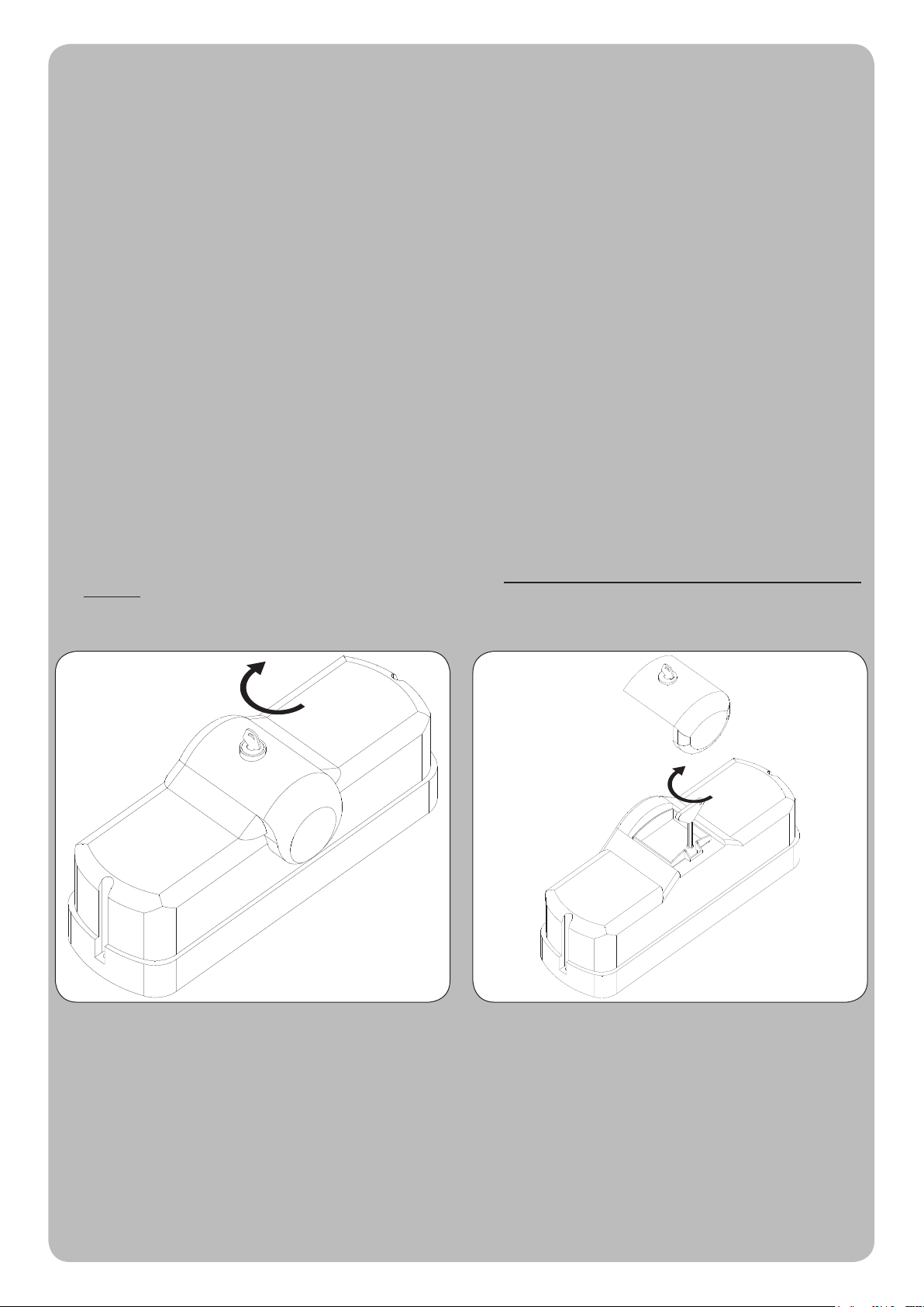
Infilare la chiave nel coperchio dello sblocco e ruotarla in senso orario. Infilare la chiave a brugola e ruotarla in senso orario.
Non forzare la rotazione della chiave a brugola, ma accertarsi
dell’avvenuto sblocco agendo contemporaneamente sull’anta del cancello.
La manovra manuale deve essere eseguita SOLO ad automazione ferma e DOPO aver tolto l’alimentazione alla centrale elettrica.
Nota: se il vostro impianto è dotato di un telecomando che dopo qualche tempo vi sembra funzionare peggio, oppure non funzionare affato, potrebbe
semplicemente dipendere dall’esaurimento della pila (a seconda del tipo, possono trascorrere diversi mesi fino a 2/3 anni). Ve ne potete accorgere
dal fatto che la spia di conferma della trasmissione è debole, oppure si accende solo per un breve istante. Prima di rivolgervi all’installatore provate
a scambiare la pila con quella di un altro trasmettitore eventualmente funzionante: se questa fosse la causa dell’anomalia, sarà sufficiente sostituire
la pila con un’altra dello stesso tipo.
Nel caso voleste aggiungere nella vostra casa un nuovo tipo di automazione, rivolgendovi allo stesso installatore e alla Tau vi garantirete, oltre che
la consulenza di uno specialista e i prodotti più evoluti del mercato, il migliore funzionamento e la massima compatibilità delle automazioni.
Vi ringraziamo per aver letto queste raccomandazioni, e vi auguriamo la massima soddisfazione dal vostro nuovo impianto: per ogni tipo di esigenza
rivolgetevi con fiducia al vostro installatore.
1
- - -- - - - - - - - - - - - - - - - - - - - - - - - - - - - - - - - - - - - - - - - - - - - - - - - - - - - - - - - - - - - - - - - - - - - - - - - - - - - - - - - - - - - - - - - - - - - - -
Page 14

English
INSTRUCTIONS AND WARNINGS FOR AUTOMATIC SYSTEM USERS
CONGRATULATIONS on choosing a Tau product for your automation system!
Tau S.r.l. produces components for automatic gates, doors, barriers and shutters. These include gear motors, control units, radio control devices,
flashing lights, photocells and accessories.
Tau products are exclusively made with top quality materials and processes and, as a company, we constantly research and develop innovative
solutions in order to make our equipment increasingly easier to use. We also pay great attention to all details (technology, appearance and
ergonomics). The extensive Tau range makes it possible for your fitter to choose the product which best meets your requirements.
Tau, however, does not produce your automated system as this is the outcome of a process of analysis, evaluation, choice of materials and
installation performed by your fitter.
Each automated system is unique, therefore, and only your fitter has the experience and professionalism required to create a system that is
tailor-made to your requirements, featuring long-term safety and reliability, and, above all, professionally installed and compliant with current
regulations.
An automated system is handy to have as well as being a valid security system. Just a few, simple operations are required to ensure it lasts for
years.
Even if your automated system satisfies regulatory safety standards, this does not eliminate “residue risks”, that is, the possibility of dangerous
situations being generated, usually due to irresponsible and/or incorrect use. For this reason we would like to give you some suggestions on how
to avoid these risks:
- Before using the system for the first time: ask your fitter to explain how residue risks can arise and read the instructions and warnings in the
user handbook that your fitter will have given you. Keep this manual for future use and, if you should ever sell your automated system, hand it
over to the new owner.
- Your automated system carries out your commands to the letter: irresponsible and/or incorrect use may cause it to become dangerous. Do
not use the system if people, animals and/or objects enter its operating area.
- IT IS NOT A TOY! Make sure children do not play near the system and keep the remote control device out of their reach.
- Faults: If you notice any abnormal behaviour, disconnect the system from the power supply immediately and perform the manual release
operation (see figure). Do not attempt to repair the door but call in your fitter: the system will operate manually as it did before installation.
- Maintenance: to ensure long life and totally safe operation, the system required routine maintenance, just like any other piece of machinery.
Establish maintenance times together with your fitter. Tau recommends a frequency of 6 months for normal domestic installations but this may
vary depending on the intensity of use (always every 3000 work cycles). It is strictly forbidden to use cleaning equipment, such as high pressure
water cleaners, and/or spray the automatic system with jets of water in general.
N.B.: All controls, maintenance work and/or repairs may only be carried out by qualified personnel.
- Do not modify the plant or the relative programming and adjustment parameters: your fitter will see to that.
N.B. Final testing, routine maintenance and any repairs must be documented by the fitter (in the relative spaces) and such documents
kept by the owner of the system (IF THE DOCUMENTS ARE NOT PRODUCED, THE WARRANTY WILL EXPIRE).
- Disposal: At the end of system life, make sure that it is demolished by qualified personnel and that the materials are recycled or disposed of
according to local regulations.
Fit the key into the cover of the release device and turn it
clockwise.
Do not force the Allen key but move the leaf door at the same
Fit the Allen key and turn it clockwise.
time to make sure it has been released.
The manual manoeuvre must only be performed with the automation inactive and AFTER having switched off the power from the mains.
N.B.: if your remote control unit (if supplied) starts working badly after a time, or does not work at all, the batteries may be flat (they can last from
several months to 2/3 years depending on what type is used). This can be seen from the fact that the transmission confirmation LED gets dimmer
or only turns on for brief moments. Before contacting your fitter, try exchanging the battery with one from a good transmitter: if this is the reason for
the fault, simply replace the battery with another one of the same type.
If you wish to add a new automated system to your house, contact your fitter and we at Tau to have the advice of a specialist, the most developed
products on the market, best operation and maximum automation compatibility.
Thank you for reading these suggestions and we trust you are fully satisfied with your new system: please contact your fitter for any further
requirements.
2
Page 15

Deutsch
ANWEISUNGEN UND HINWEISE FÜR DEN BENUTZER DER AUTOMATISIERUNG
WIR GRATULIEREN IHNEN zur Wahl eines Tau Produktes für Ihre Automatisierung!
Tau S.r.l. stellt Komponenten für die Automatisierung von Toren, Türen, Schranken und Fenstern her: Getriebemotoren, Steuerzentralen,
Funksteuerungen, Blinkleuchten, Fotozellen und Zubehör.
Die Tau Produkte werden nur mit Materialien und Bearbeitungen hoher Qualität hergestellt, und unsere Firma ist auf der ständigen Suche nach
innovativen Lösungen, mit denen die Benutzung unserer Apparaturen, die in jeder Hinsicht (Technik, Aussehen und Ergonomie) besonders gepflegt
sind, immer einfacher wird: unter dem großen Tau Sortiment kann Ihr Installateur das Produkt auswählen, das Ihrem Bedarf am besten entspricht.
Tau ist aber nicht der Hersteller Ihrer Automatisierung, die dagegen das Ergebnis des Werks Ihres Vertrauensinstallateurs ist, der sich mit den
notwendigen Untersuchungen und Bewertungen, der Wahl der Materialien und der Verwirklichung die Anlage beschäftigen wird.
Jede Automatisierung ist daher einzigartig und nur Ihr Installateur kann eine Anlage ausführen, die Ihrem Bedarf entspricht (er besitzt die notwendige
Erfahrung und Professionalität), die sicher und auf Zeit zuverlässig und vor allem fachgerecht ist und mit den gültigen Vorschriften übereinstimmt.
Eine Automatisierungsanlage ist etwas wirklich bequemes, aber auch ein gutes Sicherheitssystem, und mit ein paar einfachen Maßnahmen wird
sie jahrelang dauern.
Auch wenn Ihre Automatisierung dem Sicherheitsniveau entspricht, das von den Vorschriften gefordert wird, schließt dies das Vorhandensein eines
„Restrisikos” nicht aus, bzw. der Möglichkeit, dass Gefahren aufgrund eines fahrlässigen und/oder falschen Gebrauchs erzeugt werden können.
Aus diesem Grund geben wir hier einige Verhaltensweisen an, um diese möglichen Restrisiken zu vermeiden:
- Bei der ersten Benutzung: bitten Sie Ihren Installateur, Ihnen den Ursprung der Restrisiken zu erklären, und lesen Sie die vorliegenden
Anweisungen und Hinweise für den Benutzer, die Ihnen vom Installateur übergeben werden. Bewahren Sie die Anleitung für zukünftige
Probleme auf, und übergeben Sie diese ggf. dem neuen Besitzer der Anlage.
- Die Automatisierungsanlage folgt getreu Ihren Befehlen: ein fahrlässiger und/oder unsachgemäßer Gebrauch kann gefährlich sein.
Betätigen Sie daher die Automatisierung nicht, wenn sich Personen, Tiere und/oder Gegenstände in ihrem Aktionskreis befinden.
- SIE IST KEIN SPIEL! Lassen Sie Kinder nicht in der Nähe der Anlage spielen und halten Sie die Fernbedienungen außer deren Reichweite.
- Störungen: schalten Sie bei jedem ungewöhnlichen Verhalten der Anlage die Stromversorgung zur Automatisierung ab und entriegeln Sie von
Hand (siehe Abbildung). Vermeiden Sie jeden persönlichen Eingriff und rufen Sie Ihren Installateur: nach dem Entriegeln wird die Anlage von
Hand funktionieren, wie vor der Installation.
- Wartung: um zu dauern und ganz sicher zu funktionieren, bedarf die Anlage wie jede andere Maschine einer periodischen Wartung. Legen Sie
die Wartungszeiten zusammen mit Ihrem Installateur fest. Tau empfiehlt für den normalen Hausgebrauch eine Wartung alle 6 Monate, was je
nach Gebrauchshäufigkeit unterschiedlich sein kann (immer ungefähr 3000 Arbeitszyklen). Es ist absolut verboten, Geräte wie Hydroreiniger
und ähnliches zur Reinigung zu benutzen und/oder direkten Wasserstrahl auf die Automatisierung zu richten.
N.B.: Eingriffe (Kontrolle, Wartung und/oder Reparatur) dürfen nur von Fachpersonal ausgeführt werden.
- Anlage und programmierte und eingestellte Parameter nicht ändern, das ist Aufgabe des Installateurs.
N.B.: Endprüfung, periodische Wartungsarbeiten und eventuelle Reparaturen müssen von dem, der sie ausführt, belegt sein (in den dazu
bestimmten Feldern); diese Unterlagen muss der Besitzer der Anlage aufbewahren (DIE GARANTIE WIRD UNGÜLTIG, FALLS DIE
DOKUMENTATION FEHLT)
- Entsorgung: stellen Sie am Ende der Lebensdauer der Anlage sicher, dass die Entsorgung durch Fachpersonal erfolgt und dass die Materialien
nach den örtlich gültigen Vorschriften recycled oder entsorgt werden.
.
Den Schlüssel in den Deckel der Entriegelung stecken und im
Uhrzeigersinn drehen.
Den Sechskantschlüssel im Uhrzeigersinn einstecken.
Die Drehung des Sechskantschlüssel nicht forcieren, sondern
durch gleichzeitige Betätigung des Torflügels sicher stellen,
dass die Entriegelung erfolgt ist.
Die manuelle Bewegung darf AUSSCHLIEßLICH bei stehendem Tor und NACH Abschalten der Versorgung zur Steuerung ausgeführt
werden.
Anmerkung: wenn eine Fernbedienung zu Ihrer Anlage gehört, die nach einer bestimmten Zeit schlechter oder gar nicht funktioniert, sollten Sie die
Batterie kontrollieren, die ganz einfach leer sein könnte (je nach Typ, kann die Batterie mehrere Monate bis 2-3 Jahre dauern). Sie können das am
Leuchtmelder bemerken, der die Übertragung bestätigt und nur schwach oder ganz kurz aufleuchten wird. Tauschen Sie die Batterie mit der eines
anderen, funktionierenden Senders aus, bevor Sie sich an den Installateur wenden: falls die Ursache der Betriebsstörung eine leere Batterie sein
sollte, genügt es, diese mit einer anderen gleichen Typs zu ersetzen.
Falls Sie Ihrem Haus eine weitere neue Automatisierung hinzufügen wollen, werden Sie sich bei Ihrem Installateur und bei Tau neben der Beratung
eines Fachmanns die fortgeschrittensten Produkte garantieren, die es auf dem Markt gibt, mit bestem Betrieb und maximaler Kompatibiltät der
Automatisierungen.
Wir danken Ihnen, dass Sie diese Hinweise gelesen haben und wünschen Ihnen volle Zufriedenheit mit Ihrer neuen Anlage. Wenden Sie sich für
jeden Bedarf vertrauensvoll an Ihren Installateur.
3
Page 16

Français
INSTRUCTIONS ET RECOMMANDATIONS DESTINÉES À L’UTILISATEUR DE L’AUTOMATISATION
FÉLICITATIONS pour avoir choisi pour votre automatisation un produit Tau !
Tau S.r.l. produit des composants pour l’automatisation de portails, portes, barrières, volets : opérateurs, logiques de commande, radiocommandes,
clignotants, photocellules et accessoires.
Les produits Tau sont réalisés exclusivement avec des matériaux et des usinages de qualité et en tant qu’entreprise, nous sommes à la recherche constante
de solutions innovantes qui simplifient de plus en plus l’utilisation de nos appareils, soignés sur tous les plans (technique, esthétique et ergonomique) : dans
la vaste gamme Tau, votre installateur peut choisir le produit qui satisfera au mieux vos exigences.
Tau toutefois ne produit pas votre automatisation qui est, en fait, le résultat d’un travail d’analyse, d’évaluation, de choix des matériaux et de réalisation de
l’installation effectué par votre installateur de confiance.
Chaque automatisation, par conséquent, est unique et seul votre installateur peut réaliser une installation suivant vos exigences (dans la mesure où il est
doté de l’expérience et de la qualification professionnelle nécessaire), sûre et fiable dans le temps et, surtout, effectuée dans les règles de l’art, c’est-à-dire
conforme aux normes en vigueur.
Une installation d’automatisation est d’une grande commodité, en plus de représenter un système de sécurité et, avec un minimum d’attentions, elle est
destinée à durer des années.
Même si l’automatisme en votre possession satisfait le niveau de sécurité requis par les normes, cela n’exclut pas l’existence d’un “risque résiduel”, c’est-àdire la possibilité que des situations de danger puissent se vérifier, à cause d’une utilisation non raisonnable et/ou erronée. Pour cette raison, nous donnons
quelques conseils sur les comportements à suivre pour éviter tout inconvénient :
- À la première utilisation : demandez à votre installateur de vous expliquer l’origine des risques résiduels et lisez ce manuel d’instructions et de
recommandations pour l’utilisateur qui vous a été remis par l’installateur. Conservez le manuel pour tout problème futur et n’oubliez pas de le remettre
à l’éventuel nouveau propriétaire de l’installation.
- L’installation d’automatisation exécute fidèlement vos commandes : une utilisation non raisonnable et/ou impropre peut devenir dangereuse.
Évitez par conséquent d’actionner l’automatisme quand des personnes, des animaux ou des objets se trouvent dans son rayon d’action.
- CE N’EST PAS UN JEU ! Faites en sorte que les enfants ne jouent pas à proximité de l’installation et conservez les télécommandes hors de leur
portée.
- Anomalies: à tout comportement anormal de l’installation, coupez l’alimentation électrique de l’automatisme et effectuez le déblocage manuel (comme
sur la figure). Évitez toute intervention personnelle et contactez votre installateur : une fois débloquée, l’installation fonctionnera manuellement, comme
avant l’automatisation.
- Maintenance : pour durer dans le temps et fonctionner en toute sécurité, comme toute autre machine, l’installation a besoin d’une maintenance
périodique. Établissez avec votre installateur un plan de maintenance. Tau conseille une intervention tous les 6 mois pour un usage domestique normal
qui peut varier suivant l’intensité d’utilisation (toujours tous les 3000 cycles de travail).
lavage tels que des nettoyeurs haute pression ou similaires et/ou d’orienter des jets d’eau en général directement sur l’automatisme.
N.B. N’importe quel type d’intervention (contrôle, maintenance et/ou réparation) doit être effectué uniquement par du personnel qualifié.
- Ne pas modifier l’installation ni les paramètres de programmation et de réglage : la responsabilité en incombe à l’installateur.
N.B. l’essai de fonctionnement final, les maintenances périodiques et les éventuelles réparations doivent être documentées (dans les espaces
prévus à cet effet) par qui les exécute et les documents doivent être conservés par le propriétaire de l’installation (EN CASE DE NONPRÉSENTATION DE LA DOCUMENTATION, LA GARANTIE N’EST PLUS VALABLE).
- Démantèlement : à la fin de la vie de l’installation, assurez-vous que le démantèlement soit effectué par du personnel qualifié et que les matériaux
soient recyclés ou mis au rebut suivant les normes en vigueur au niveau local.
Il est absolument interdit d’utiliser des équipements pour le
Enfiler la clé dans le couvercle du débrayage et la tourner dans
des aiguilles d’une montre.
Enfiler la clé Allen dans le sens aiguilles d’une montre.
Ne pas forcer la rotation de la clé Allen mais s’assurer du
blocage en agissant en même temps aussi sur le battant.
La manœuvre manuelle doit être exécutée UNIQUEMENT avec l’automatisme à l’arrêt et APRÈS avoir coupé l’alimentation de l’armoire
de commande.
Note : si votre installation est munie d’une télécommande qui au bout de quelques temps semble moins bien fonctionner ou ne plus fonctionner du
tout, cela peut dépendre tout simplement de la pile (suivant le type sa durée est de plusieurs mois jusqu’à 2/3 ans). Vous pouvez vous en rendre
compte à travers le fait que le voyant de confirmation de la transmission est faible ou bien, s’il ne s’allume qu’un bref instant. Avant de vous adresser
à l’installateur, essayez d’échanger la pile avec celle d’un autre émetteur qui fonctionne correctement : si la cause de l’anomalie est celle-ci, il suffira
de remplacer la pile par une autre du même type.
Si vous désirez ajouter un nouveau type d’automatisme dans votre habitation, adressez-vous au même installateur et à Tau ; en plus du conseil d’un
spécialiste, vous aurez ainsi la garantie des produits les plus évolués sur le marché, du meilleur fonctionnement et du maximum de compatibilité
entre les automatismes.
Nous vous remercions d’avoir lu ces recommandations et nous espérons que votre nouvelle installation vous donnera toute satisfaction : pour tout
type d’exigence, adressez-vous en toute confiance à votre installateur.
4
Page 17

125
1
7
8
3
6
301,5
2
433
131,5
70
70
140
4
g. 1
9
10
g. 2
6
8
7
5
Staffa attacco anta
Wing connection bracket
Toranschlussbügel
Patte de fixation porte
Brida de fijación de la hoja
g. 3
ZIP Series DISEGNI - DRAWINGS - ZEICHNEN - PROJETS - DIBUJOS
ZIP Series
g. 4
13
- - -- - - - - - - - - - - - - - - - - - - - - - - - - - - - - - - - - - - - - - - - - - - - - - - - - - - - - - - - - - - - - - - - - - - - - - - - - - - - - - - - - - - - - - - - - - - - - -
Page 18

A
≥A
A
max.
380 mm
<170°
90°
g. 5
max. 3500 mm
≥A
max.
380 mm
<170°
90°
g. 6
14
g. 7 g. 8
ZIP Series DISEGNI - DRAWINGS - ZEICHNEN - PROJETS - DIBUJOS
ZIP Series
Page 19

A
F
g. 9
A
g. 10
C
F
E
D
E
F
B
g. 11
ZIP Series DISEGNI - DRAWINGS - ZEICHNEN - PROJETS - DIBUJOS
ZIP Series
g. 12
15
Page 20

5
7
2 x 1 mm² + RG58
RX
4 x 0,5 mm²
1
2 x 1 mm²
TX
2
6
2 x 0,5 mm²
6
3
RX
4 x 1,5 mm²
1
6
4 x 0,5 mm²
4
3 x 0,5 mm²
4 x 1,5 mm²
3 x 1,5 mm² 230V AC
6
3
TX
2 x 0,5 mm²
8
g. 13
5
7
2 x 1 mm² + RG58
RX
4 x 0,5 mm²
1
2 x 1 mm²
TX
6
2
2 x 0,5 mm²
6
2 x 2,5 mm² + Encoder 3 x 0,5 mm²
1
6
4 x 0,5 mm²
4
3 x 0,5 mm²
2 x 2,5 mm²
+ Encoder
3 x 0,5 mm²
3 x 1,5 mm² 230V AC
6
3
TX
2 x 0,5 mm²
8
16
3
RX
g. 14
ZIP Series DISEGNI - DRAWINGS - ZEICHNEN - PROJETS - DIBUJOS
ZIP Series
- - -- - - - - - - - - - - - - - - - - - - - - - - - - - - - - - - - - - - - - - - - - - - - - - - - - - - - - - - - - - - - - - - - - - - - - - - - - - - - - - - - - - - - - - - - - - - - - -
Page 21

Español
INSTRUCCIONES Y ADVERTENCIAS DESTINADAS AL USUARIO DE L’AUTOMATISMO
¡FELICITACIONES por haber elegido un producto TAU para su automatización!
Tau S.r.l. produce componentes para la automatización de cancelas, puertas, barreras, cerramientos, tales como: motorreductores, centrales de
mando, radiomandos, luces intermitentes, fotocélulas y accesorios.
Los productos Tau son fabricados sólo con materiales de calidad y excelentes mecanizados. Nuestra empresa busca constantemente soluciones
innovadoras que simplifiquen aún más el uso de nuestros aparatos, los que son cuidados bajo todo aspecto (técnico, estético y ergonómico): en la
gran gama Tau, su instalador puede escoger el producto que satisfaga de la mejor manera sus exigencias.
Tau no es quien escoge los componentes de su automatización, este es un trabajo de análisis, evaluación, elección de los materiales y realización
de la instalación efectuado por su instalador de confianza.
Por lo tanto, cada automatización es única y sólo su instalador puede ejecutar una instalación a medida de sus exigencias (puesto que cuenta con
la experiencia y profesionalidad necesarias), segura y fiable en el tiempo y, sobre todo, que respete las normativas vigentes.
Una instalación de automatización es una gran comodidad, además de un sistema de seguridad válido y, con un mantenimiento reducido y sencillo,
está destinada a durar por mucho tiempo.
Aunque bien su automatización satisfaga el nivel de seguridad requerido por las normativas, esto no excluye la existencia de un “riesgo residual”, es
decir, la posibilidad de que se puedan crear situaciones de peligro causadas por un uso inconsciente o incorrecto. Por dicho motivo, a continuación
le damos algunos consejos sobre cómo comportarse para evitar inconvenientes:
- La primera vez que se usa: pida a su instalador que le explique el origen de los riesgos residuales y lea este manual de instrucciones y
advertencias para el usuario entregado por el instalador. Conserve el manual por cualquier problema que pueda surgir y recuerde entregarlo a
un posible nuevo dueño de la instalación.
- La instalación de automatización ejecuta fielmente los mandos dados: un uso inconsciente o inadecuado puede ser peligroso. Por
consiguiente, no accione la automatización cuando en su radio de acción haya personas, animales o cosas.
- ¡NO ES UN JUGUETE! Trate de que los niños no jueguen cerca de la instalación y mantenga los controles remotos lejos de su alcance.
- Desperfectos: cada vez que la instalación no funcione correctamente, corte la alimentación eléctrica de la automatización y realice el
desbloqueo manual (como muestra la figura). No realice ninguna reparación y llame a su instalador: una vez desbloqueada, la instalación
funcionará manualmente como antes de montar la automatización.
- Mantenimiento: para garantizar una larga vida útil y para un funcionamiento seguro, la instalación, al igual que cualquier otra maquinaria,
requiere un mantenimiento periódico. Establezca con su instalador las frecuencias de dicho mantenimiento. Tau aconseja realizar un
mantenimiento cada 6 meses para un uso residencial normal, que puede variar según la intensidad de uso (siempre cada 3000 ciclos de
trabajo). Queda terminantemente prohibido utilizar equipos para la limpieza del tipo máquina de chorro de agua a alta presión y similares, y/o
dirigir chorros de agua en general directamente sobre la automatización.
N.B. cualquier tipo de operación (control, mantenimiento o reparación) debe ser realizada sólo por personal cualificado.
- No modifique la instalación ni los parámetros de programación y regulación: la responsabilidad es del instalador.
N.B.: el ensayo final, los trabajos de mantenimiento periódico y las posibles reparaciones deben ser documentados (en los espacios
disponibles) por quien los efectúa y los documentos tienen que ser conservados por el dueño de la instalación (LA FALTA DE
DOCUMENTACIÓN DETERMINA LA CADUCIDAD DE LA GARANTÍA).
- Desguace: al final de la vida útil de la instalación, el desguace debe ser realizado por personal cualificado y los materiales deben ser reciclados
o eliminados según las normas locales vigentes.
Introduzca la llave en la tapa del desbloqueo y gírela hacia la derecha. Gire la llave Allen en el sentido orario.
No fuerce la rotación de la llave Allen sino que controle que el desbloqueo
se haya realizado, actuando simultáneamente también sobre la hoya.
La maniobra manual debe efectuarse SOLAMENTE con la automatización detenida y DESPUÉS de haber cortado la alimentación a la
central eléctrica.
Nota: si su instalación está dotada de un control remoto que, transcurrido un cierto período, no funciona correctamente o deja de funcionar, podría
ser que la pila esté agotada (dura desde varios meses a 2/3 años según el modelo). Ud. se podrá dar cuenta de este inconveniente por el hecho de
que la luz del indicador de confirmación de la transmisión es débil, o bien se enciende sólo durante un breve instante. Antes de llamar al instalador,
pruebe sustituir la pila con una de otro transmisor que funcione correctamente: si el problema fuera este, sustituya la pila con otra del mismo tipo.
Si Ud. deseara montar en su casa un nuevo tipo de automatización, contacte al mismo instalador y a Tau, así podrá tener la garantía de
un asesoramiento de un experto y los productos más modernos del mercado, el mejor funcionamiento y la máxima compatibilidad de las
automatizaciones.
Le agradecemos por haber leído estas recomendaciones y esperamos que esté satisfecho de su nueva instalación: ante cualquier exigencia,
contacte con confianza a su instalador.
5
Page 22

Data
Date
Datum
Date
Fecha
Descrizione intervento
Description of job
Beschreibung des Eingriffs
Description intervention
Descripción del trabajo
Parti sostituite
Parts replaced
Ersetzte teile
Parties remplacées
Piezas sustituidas
Firma manutentore
Fitter’s signature
Unterschrift des
Wartungsmannes
Signature réparateur
Firma del técnico
Firma utilizzatore
User’s signature
Unterschrift des
Benutzers
Signature utilisateur
Firma del usuario
6
Page 23

Data
Date
Datum
Date
Fecha
Descrizione intervento
Description of job
Beschreibung des Eingriffs
Description intervention
Descripción del trabajo
Parti sostituite
Parts replaced
Ersetzte teile
Parties remplacées
Piezas sustituidas
Firma manutentore
Fitter’s signature
Unterschrift des
Wartungsmannes
Signature réparateur
Firma del técnico
Firma utilizzatore
User’s signature
Unterschrift des
Benutzers
Signature utilisateur
Firma del usuario
7
Page 24

Data
Date
Datum
Date
Fecha
Descrizione intervento
Description of job
Beschreibung des Eingriffs
Description intervention
Descripción del trabajo
Parti sostituite
Parts replaced
Ersetzte teile
Parties remplacées
Piezas sustituidas
Firma manutentore
Fitter’s signature
Unterschrift des
Wartungsmannes
Signature réparateur
Firma del técnico
Firma utilizzatore
User’s signature
Unterschrift des
Benutzers
Signature utilisateur
Firma del usuario
8
- - -- - - - - - - - - - - - - - - - - - - - - - - - - - - - - - - - - - - - - - - - - - - - - - - - - - - - - - - - - - - - - - - - - - - - - - - - - - - - - - - - - - - - - - - - - - - - - -
Page 25

INSTALLATIONS MATERIALIEN (Abb. 2)
1_ COD P-650ZIP Getriebemotor ZIP
2_ COD P-150BAR Gelenkarm + Verankerungs-
platte
3_ COD S-150BAR0020 Stange mit Beschlag für Ge-
lenkarm
4_ COD S-150BAR0030 Stange mit Löchern für Gelen-
karm
5_ COD S-650RBS0030 Anschlussbügel
6_ COD M-V350AM12A0 Selbstsichernde Mutter E M12
7_ COD M-V100012035I rostfrei Schraube TE M12x35
8_ COD M-V500012036I rostfrei das Röschen D.12x36
9_ COD M-V500008024I rostfrei das Röschen D.8x24
10_ COD M-V100008016I rostfrei Schraube TE M8x16
ERLÄUTERUNG DER AUTOMATISIERUNG
Es muss unter zwei Motortypen unterschieden werden:
1 - nicht selbsthemmender Motor = die Automatisierung ist nicht
mit Entriegelung ausgestattet
2 - selbsthemmender Motor = die Automatisierung ist mit
Entriegelung ausgestattet.
Es wird folglich empfohlen, das Elektroschloss in den zwei Fällen
zu installieren:
1° der Motor ist reversibel und der Flügel ist länger als 1,6 Meter
2° unabhängig vom Motortyp, falls der Flügel sehr lang und daher
in Öffnung und Schließung Schwingungen ausgesetzt ist.
Der Getriebemotor ZIP kann auf Wunsch mit elektrischen Endschaltern im Motor geliefert werden.
EINLEITENDE EMPFEHLUNGEN FÜR DIE INSTALLATION
Das von Ihnen gewählte System löst mit Leichtigkeit jedes Installationsproblem in den am weitest verbreiteten Fällen der Hausund
Wohnbereichautomatisierung.
Trotzdem haben sich die folgenden Empfehlungen als nützlich erwiesen:
1. Den Getriebemotor so nah wie möglich an dem zu automa-
tisierenden Flügel und auf jeden Fall dort installieren, wo die
Öffnung nicht behindert wird.
2. Da die Länge des Gelenkarms die Befestigungsposition des
Bügels für die Verankerung an dem Flügel bestimmt, wird empfohlen:
- Den Armabschnitt, der an dem Motor angeschlossen ist,
2-3 Zentimeter länger als die Mindestlänge halten.
- Den Armabschnitt, der an dem Flügel angeschlossen ist,
einige Zentimeter kürzer als die Höchstlänge halten.
3. Bevor auch der Bügel befestigt wird, versuchen, den Flügel
manuell zu bewegen (mit freigegebenem Getriebemotor), und
überprüfen, ob die Automatisierung in der Lage ist, den von
Ihnen gewünschten Winkel zu öffnen.
BITTE BEMERKEN: für höchste Sicherheit ist die Installation
der mechanischen Bodenendanschläge im Auf und Zu mit
Gummistopfen Picht, wie in Abbildungen 13 und 14 gezeigt.
BEFESTIGUNG DER VERANKERUNGSPLATTE (Abb. 3)
Für die Befestigung Spreizdübel verwenden (bei gemauertem
Pfeiler) oder bohren und gewindeschneiden (wenn der Pfeiler aus
Metall besteht).
BEFESTIGUNG DES BÜGELS FÜR DIE VERANKERUNG
AN DEM FLÜGEL (Abb. 4)
Selbstschneidende Schrauben verwenden, um den Bügel dort zu
befestigen, wo dies unter Berücksichtung der “Einleitenden Emfehlungen für die Installation” festgelegt worden ist.
VERANKERUNG UND INSTALLATION DES GETRIEBEMOTORS
Der Arm ist kein Teleskoparm, daher muss während der Installation die korrekte Position festgelegt werden, so dass der Gelenkarm
und die Stange mit Beschlag einen Winkel < 170° bilden, wenn die
zwei Flügel geschlossen sind.
Siehe Abb. 5 und Abb. 6, um die Bedeutung des obigen besser zu
verstehen. Den Getriebemotor zur Vereinfachung der Installation
zu entriegeln.
Nachdem die Verankerungsplatte und der Anschlussbügel befestigt worden sind, wie folgt vorgehen:
1_ den Getriebemotor mit 4 Schrauben TE M6x120, 4 Unterleg-
scheiben Ø6x12x1,2 und 4 selbstsichernden, hohen Muttern
M6, wie auf der Zeichnung gezeigt, an der Platte befestigen;
2_ für die Befestigung die 4 durchgehenden Löcher im Aluminium-
gehäuse des Getriebemotors benutzen; die Unterlegscheibe
zwischen Mutter und Motor anordnen;
3_ die Stange mit Beschlag an der Motorwelle befestigen und eine
Mutterschraube anschrauben; sicherstellen, dass die Stange
fest blockiert ist und sich nicht zufällig während des Gebrauchs
lösen kann;
4_ die Stange mit Löchern mit ihrer Schraube + Mutter am Bügel
befestigen, der am Torügel befestigt worden ist;
5_ nachdem die Kabel für die Elektroanschlüsse durch die Löcher
in der Platte geführt worden sind, das Gehäuse einsetzen und
wie in Abb. 7 und Abb. 8 gezeigt mit 2 Schrauben TCEI M6x40
befestigen.
MANUELLE ENTRIEGELUNGS (Abb. 9 - Abb. 10)
Anmerkung: Die Drehung des Sechskantschlüssels (A, Abb. 10)
nicht forcieren, sondern durch gleichzeitige Betätigung des Torügels sicher stellen, dass die Entriegelung erfolgt ist.
ELEKTRISCHER ANSCHLUß AN DEN MOTOR
• Den Anschluß unter Ausnutzung der freien Öffnung an der Verankerungsplatte vornehmen.
• Die Kabel mit einem exiblen Mantel schützen.
• Kabel mit einem Mindestdurchmesser von 1,5 mm² verwenden.
• Werden die Anschlüße vertauscht, so wird die Drehrichtung
des Motors umgekehrt.
Positionieren Sie das Steuergerät (falls extern) in
der unmittelbaren Nähe der Motoren.
Vermeiden Sie es, die Kabel der Zusatzvorrichtungen in den Kabelkanälen zu verlegen, in denen andere Kabel vorhanden sind, die große Lasten oder
Lampen mit elektronischem Starter speisen.
Falls Tasten oder Kontrollleuchten in Wohnungen
oder Gebäuden installiert werden, die mehrere Meter vom Steuergerät entfernt sind, empfehlen wir die
Abkopplung des Signals über ein Relais, um Störungen zu vermeiden.
ALLGEMEINE EMPFEHLUNGEN
- Die Sicherheit des Gittertores in Übereinstimmung mit den gültigen Vorschriften integrieren.
- Es sollten kurzen Strecken für die Kabel gewählt und die Leistungskabel von den Steuerkabeln getrennt gehalten werden.
- Die Steuerkarte muß in einem dichten Gehäuse installiert werden.
- Das Gerät richtig erden.
- Für die Einstellung des maximalen Drehmomentes des Getriebemotors muß sich an die gültigen Vorschriften gehalten werden.
- In Übereinstimmung mit den europäischen Sicherheitsnormen
wird die Installation eines externen Schalters empfohlen, um
die Stromzufuhr bei einer Wartung des unterbrechen zu können.
- Überprüfen, ob jede einzelne installierte Vorrichtung leistungsfähig und wirksam ist.
- Leicht lesbare Schilder anbringen, die darüber informieren,
daß ein motorisiertes Gittertor vorhanden ist.
- Auch wenn der Getriebemotor mit allen Sicherheitsvorrichtungen ausgestattet wird, sollte jede Einrichtung, die fähig ist, die
Öffnung des Tors zu steuern und die zufällig ohne Überwachung benutzt werden könnte, außerhalb der Reichweite von
Kindern oder Unbefugten gehalten werden.
GEBRAUCH
Der Getriebemotor ZIP wurde für die Automatisierung von Drehtoren mit vertikaler Achse und Flügellänge nicht über 3500 mm
entwickelt.
Es wird ausdrücklich verboten, die Vorrichtung für unterschiedliche
Zwecke oder unter Umständen einzusetzen, die von den genannten abweichen.
Normalerweise ermöglicht die installierte elektronische Steuerzentrale die Wahl der Funktion:
DEUTSCH
ZIP Series
17
Page 26

Automatisch: Ein Steuerimpuls führt das Öffnen und das
Halbautomatisch: Ein Steuerimpuls führt das Öffnen oder das
Im Falle von manuellem Betrieb, zuerst die Entriegelung betätigen.
Es wird daran erinnert, daß es sich um eine automatische Vorrichtung handelt, die mit Strom gespeist wird und daher mit
Vorsicht zu verwenden ist. Im besonderen wird vor folgendem gewarnt:
• die Vorrichtung nicht mit feuchten Händen und/oder feuchten
oder nackten Füßen berühren;
• die Stromzufuhr unterbrechen, bevor das Steuergehäuse und/
oder der Getriebemotor geöffnet werden;
• Den Motor nur berühren, wenn Sie sicher sind, dass er abgekühlt ist;
• das Gittertor nur in Bewegung setzen, wenn es vollständig
sichtbar ist;
• sich außerhalb des Aktionsradius des Gittertores aufhalten,
wenn sich dieses in Bewegung bendet;
• Kinder oder Tiere nicht in der Nähe des Gittertores spielen lassen;
• Kinder oder unfähige Personen nicht die Fernsteuerung oder
andere Vorrichtungen für die Betätigung verwenden lassen;
• eine periodische Wartung durchführen;
• im Falle einer Störung die Stromzufuhr unterbrechen und das
DEUTSCH
Gittertor nur dann manuell betätigen, wenn dies möglich und
sicher ist. Keine Eingriffe durchführen und einen autorisierten
Techniker rufen.
Schließen des Gittertores durch.
Schließen des Gitterlores durch.
WINDDRUCK
NB: If the gearmotor is installed on solid swing gates in a windy
area, max. motor torque must always be calibrated to less than
15 Kg (measured on the closing edge – as established by prEN
13241 and prEN 12635). If torque is calibrated to exceed this safety threshold, TAU declines all responsibility for damage to people.
WARTUNG
Die Getriebemotoren ZIP erfordern wenig Wartung. Trotzdem
hängt ihre gute Funktion auch von dem Zustand des Gittertores
ab: aus diesem Grunde beschreiben wir kurz auch die Tätigkeiten, die durchzuführen sind, um das Gittertor immer leistungsfähig
zuhalten.
Achtung: Niemand, mit Ausnahme des Wartungstechnikers, bei
dem es sich um einen spezialisierten Techniker handeln muß,
darf das automatische Gittertor während der Wartungsarbeiten
bedienen können. Aus diesem Grunde sollte die Versorgung mit
Netzstrom unterbrochen werden, um so auch die Gefahr eines
Stromschlags zu vermeiden. Muß hingegen die Stromversorgung
für einige Überprüfungen vorhanden sein, so ist es erforderlich,
daß jede Steuervorrichtung, mit Ausnahme der Vorrichtung, die
vom Wartungstechniker benutzt wird, kontrolliert oder deaktiviert
wird (Fernsteuerungen, Druckknopftafel, etc.).
Automatisierungsanlage
• Den Zapfen des Gelenkarms, den Beschlag, der in Verbindung
mit der Motorabtriebswelle arbeitet, und alle Teile geölt halten,
die Verschleiss aufgrund von Reibung ausgesetzt sind.
• Die Funktion der Sicherheitsvorrichtungen (Photozelle, Sicherheitsleiste, Drehmomenntbegrenzer, etc.).
Gewöhnliche Wartung
• Jede der folgenden Arbeiten muss wenn nötig und mindestens
alle 6 Monate für den normalen Hausgebrauch (ungefähr 3000
Arbeitszyclen) und alle 2 Monate für den intensiven Gebrauch
z. B. Wohnblockbetrieb (immer ungefähr 3000 Arbeitszyklen).
Außerordentliche Wartung
• Wenn nicht banale Eingriffe an den mechanischen Teilen erforderlich werden, empehlt es sich, den Getriebemotor auszubauen, um ihn von den Technikern des Herstellers oder von
ihm autorisierten Vertragshändlern reparieren zu lassen.
NACHTRAG (Abb. 11 - Abb. 12)
WELCHE SICHERHEITSFREIRÄUME MUSS ICH EINHALTEN,
WENN ICH EIN TOR AUTOMATISIERE?
• Der Abstand A, Abb. 11, zwischen Pfosten und Ständer neben
dem Tor muss während der Tordrehung gleich bleiben. Ändert
sich der Abstand, so muss der Höchstabstand in der gesamten
Höhe max. 25 mm sein, andernfalls muss der so zugänglich
gewordene Raum in der gesamten Torhöhe bis max. 2,5 m
ausgefacht werden.
• Der Abstand B in Abb. 11 zwischen Boden und Torügel muss
mindestens 50 mm sein; falls der Abstand B aufgrund der Neigung des Bodens variabel ist, so ist es dem Installateur überlassen, Maßnahmen zur Reduzierung der Mitnehmgefahr anzuwenden.
18
• An einem zweiteiligen Tor muss der Abstand C in Abb. 12 zwischen den beiden geschlossenen Torügeln mindestens 2,5
cm sein; dieser Abstand kann mit einer Sicherheitsleiste an der
Kante des einen Torügels oder einem verformbaren, elastischen Element im Freiraum zugedeckt werden. Der Abstand
kann auch kleiner oder gleich Null sein, in diesem Fall müssen
sich die Torügel aber verstellt schließen, so dass ein Raum D
von 50 cm, Abb. 12 entsteht.
HINWEISE FÜR EINE SICHERE INSTALLATION
Totmannbetrieb: es genügt eine Notstopvorrichtung und eine
Blinkleuchte
Automatischer / halbautomatischer Betrieb: eine Blinkleuchte muss installiert werden, und der Motordrehmoment muss wie
später beschrieben eingestellt werden; falls diese Einstellung nicht
möglich ist, muss eine Sicherheitsleiste installiert werden.
• zwei Fotozellen anbringen, die eine außerhalb und die andere
innerhalb des Laufwegs, um den Bewegungsbereich des Tors
einzugrenzen. Im Falle einer Überlagerung der Torügel mit
Anschlagleiste müssen sie verstellt angebracht werden (Distanz D Abb. 12).
Für jede Betriebsweise: Wenn der Torügel in Öffnung an einem
festen Hindernis (kleine Mauer, Wand, Pfeiler, usw.) mit einem Abstand (siehe Abbildung auf der vorherigen Seite) anhält, der kleiner als 40 cm ist, so muss am Torügel oder am festen Teil eine
Sicherheitsleiste nach folgenden Kriterien angebracht werden:
1 - wenn es sich um ein Hindernis handelt, dass sich vorherr-
schend in der Höhe (also senkrecht) ausdehnt, so wird die Sicherheitsleiste (in der ganzen Länge des oben genannten Hindernisses) in einer Höhe zwischen 40 und 60 cm ab Fußboden
angebracht;
2 - wenn es sich um ein Hindernis handelt, dass sich vorherr-
schend in der Breite (also waagerecht) ausdehnt und eine
Höhe unter 60 cm hat, so wird die Sicherheitsleiste 5 cm ab
der oberen Kante des Hindernisses angebracht.
MERKMALE, EINSTELLUNGEN UND INSTALLATION
DER SICHERHEITSVORRICHTUNGEN
Photozellen :
• Sie werden auf einer Höhe zwischen 40 und 60 cm ab Boden
und in einem Höchstabstand von 10 cm ab Kante des geöffneten Torügels und ab Rand des geschlossenen Tors angebracht.
Sensible Sicherheitsleiste
• Im einfachsten Fall muss es sich um gewöhnlich geschlossene
NC-Kontakte handeln;
• Die Elastizität bzw. Mindestverformung muss mindestens 1 cm
größer sein als der Raum, den das Tor ab Ansprechen der
Vorrichtung zum Stillstand benötigt.
Drehmomentbegrenzer
• Muss so eingestellt werden, dass der Torügel bei Vorhandensein eines mechanischen Widerstands von 150 N (ca. 15 kg),
an seiner Kante gemessen, anhält, wobei die kinetische Energie des Torügels nicht größer als 10 J sein darf.
ANLAGE DES TYPS ZIP (Abb. 13)
1 Getriebemotor ZIP
2 Elektroschloß
3 Anschläge
4 Steuerzentrale
5 Antenne und Blinkclicht
6 Photozellen
7 Schlüsselsschal-ter
8 Hauptschalter
ANLAGE DES TYPS ZIP12 (Abb. 14)
1 Getriebemotor ZIP
2 Elektroschloß
3 Anschläge
4 Steuerzentrale
5 Antenne und Blinkclicht
6 Photozellen
7 Schlüsselsschal-ter
8 Hauptschalter
Die Höchstlänge zwischen Steuerung und Motor darf 10 – 12 m
nicht überschreiten.
ZIP Series
Page 27

INTEGRIERUNGSERKLÄRUNG DES HERSTELLERS
(gemäß der Europäischen Richtlinie 2006/42/EG Anl. II.B)
Hersteller: TAU S.r.l.
Adresse: Via E. Fermi, 43
36066 Sandrigo (Vi)
ITA LY
Erklärt unter seiner Haftung, dass das Produkt: Elektromechanischer Antrieb
für die automatische Bewegung von: Drehtore
für eine Anwendung: Privat / Gewerbe
Einschließlich: -
Modell: ZIP
Typ: ZIP / ZIP12
Seriennummer: SIEHE SILBERETIKETTE
Handelsbezeichnung: DREHTORANTRIEB FÜR PRIVAT UND GEWERBE
ausgeführt wurde, um in einen Verschluss integriert zu werden (Drehtore) oder um mit anderen Vorrichtungen kombiniert zu werden,
um diesen Verschluss zu bewegen, und somit gemäß der Maschinenrichtlinie 2006/42/EG eine Maschine darstellt.
Außerdem erklärt er, dass dieses Produkt den grundsätzlichen Sicherheitseigenschaften der folgenden Richtlinien EWG entspricht:
- 2006/95/EG Niederspannungsrichtlinie
- 2004/108/EG Richtlinie für elektromagnetische Kompatibilität
Und wo gefordert, der Richtlinie:
- 1999/5/CE Radio equipment and telecommunications terminal equipment
Außerdem wird erklärt, dass es nicht zugelassen ist, die Vorrichtung in Betrieb zu setzen, bis die Maschine, in die sie integriert wird
oder deren Bestandteil sie sein wird, identiziert und die Konformität gegenüber dem Inhalt der Richtlinie 2006/42/EG erklärt wurde.
Er verpichtet sich, auf ausdrücklichen Wunsch der nationalen Behörden, Informationen über die Fastmaschinen zu übersenden.
Sandrigo, 31/03/2010
Der gesetzliche Vertreter
_________________________________________
Bruno Danieli
Name und Adresse der beauftragten Person zur Vorlegung der zugehörigen technischen Unterlagen:
Loris Virgilio Danieli - via E. Fermi, 43 - 36066 Sandrigo (Vi) Italy
ZIP Series
19
Page 28
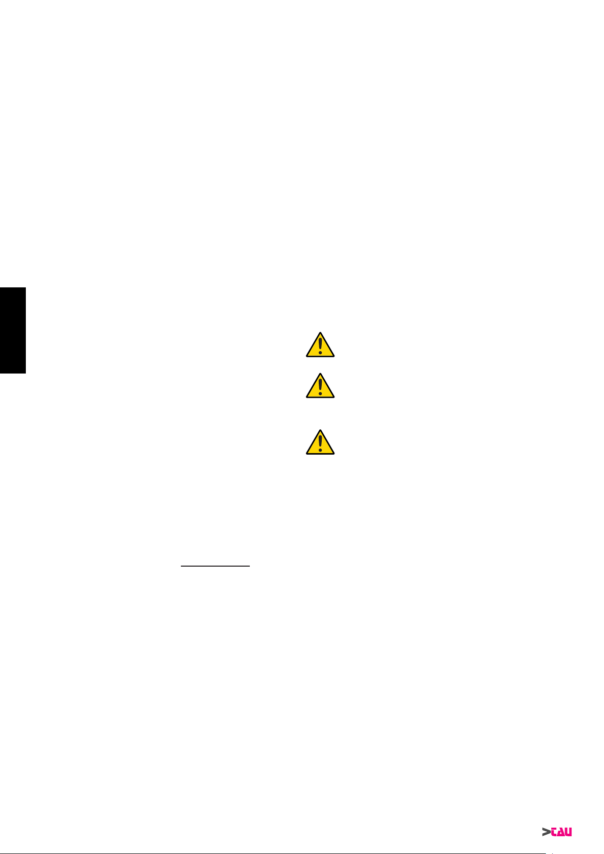
MATERIEL POUR L ’INSTALLATION (g. 2)
1_ COD P-650ZIP motoréducteur ZIP
2_ COD P-150BAR bras articulé + plaque d’an-
crage
3_ COD S-150BAR0020 barre avec rivet pour bras arti-
culé
4_ COD S-150BAR0030 bras avec trou pour bras arti-
culé
5_ COD S-650RBS0030 patte de xation
6_ COD M-V350AM12A0 crou E autobloquant M12 haut
7_ COD M-V100012035I vis à six pans M12x35 inox
8_ COD M-V500012036I rondelle plaine D.12x36 inox
9_ COD M-V500008024I rondelle plaine D.8x24 inox
10_ COD M-V100008016I vis à six pans M8x16 inox
PRESENTATION DE L’AUTOMATISME
Il faut faire la distinction entre deux types de motorisations:
1 - moteur réversible = l’automatisme n’est pas muni de
déblocage
2 - moteur non réversible = l’automatisme est muni de déblo-
cage
Par conséquent, il est conseillé d’installer la serrure électrique
dans deux cas:
1° le moteur est de type réversible et la longueur du battant dé-
passe 1,6 mètres
2° indépendamment du type de moteur, si le battant est très long
et donc sujet à des oscillations durant la manoeuvre d’ouverture et de fermeture.
Le motoréducteur ZIP peut être équipé, sur demande, de microin-
terrupteurs de n de course électriques à l’intérieur du moteur.
FRANCAIS
1_ ancrer le motoréducteur à la plaque à l’aide de 4 vis à six pans
M6x120, 4 rondelles Ø 6x12x1,2 et 4 écrous M6 hauts autobloquants comme le montre le dessin
2_ pour la xation, utiliser les 4 trous passants se trouvant sur la
carcasse en aluminium du motoréducteur; placer la rondelle
entre l’écrou et le moteur
3_ xer la barre avec rivet à l’arbre de sortie moteur en le bloquant
avec un boulon; s’assurer que la barre est solidement bloquée
et ne peut pas se détacher accidentellement durant le fonctionnement
4_ avec la vis et l’écrou prévus à cet effet, xer la barre avec trous
à la patte xée sur le battant du portail
5_ après avoir passé les câbles pour le branchement électrique,
en utilisant les trous présents sur la plaque, enler le carter et
le xer avec 2 vis à six pans en creux comme l’illustre la g. 7
et la g. 8.
DEBLOCAGE MANUEL (g. 9 - g. 10)
Note: Ne pas forcer la rotation de la clé Allen (A g. 10) mais
s’assurer du blocage en agissant en même temps aussi sur
le battant.
BRANCHEMENT ELECTRIQUE AU MOTEUR
• Effectuer le branchement en utilisant le trou libre sur la plaque
d’ancrage.
• Protéger les câbles avec une gaine exible.
• Utiliser des câbles d’une section minimum de 1,5 mm².
• Quand on invertit les connexions, le moteur invertit le sens de
rotation.
Placer la centrale de commande (si externe) le plus
proche aux moteurs.
CONSIDERATIONS PRELIMINAIRES A L’INSTALLATION
Le système que vous avez choisi résout brillament n’importe quel
problème d’installation dans les cas les plus courants d’automatisation domestique et résidentielle.
Nous jugeons toutefois utile de fournir les conseils suivants:
1. Installer le motoréducteur le plus près possible du battant à
automatiser et dans tous les cas à un emplacement ne gênant
pas l’ouverture.
2. Dans la mesure où la longueur du bras articulé détermine la
position de montage de la patte de xation au battant, nous
conseillons de:
- maintenir la longueur du segment de bras relié au moteur
inférieure de deux-trois centimètres à son minimum ;
- maintenir la longueur du segment de bras relié au battant
inférieure de quelques centimètres à son maximum.
3. Débloquér et vérier si le dispositif d’automatisation parvient à
ouvrir le battant suivant l’angle désiré.
Note : pour une sécurité complète, il est obligatoire d’installer,
s’il n’y en a pas, les arrêts mécaniques (butées au sol) avec
bouchon en caoutchouc en ouverture et fermeture, comme
indiqué sur les illustrations 13-14.
FIXATION DE LA PLAQUE D’ANCRAGE (g. 3)
Pour la xation, utiliser des vis tamponnées (quand le pilier est en
maçonnerie) ou bien percer et leter (si la plaque est assemblée à
une structure métallique).
FIXATION PATTE DE FIXATION AU BATTANT (g. 4)
Utiliser des vis-taraud pour xer la patte à l’emplacement déterminé suivant les indications du paragraphe “Considérations préliminaires à l’installation”.
ANCRAGE ET INSTALLATION DU MOTOREDUCTEUR
Le bras n’est pas de type télescopique, en phase d’installation, il
n’est donc pas nécessaire de déterminer la position correcte de
manière que le bras articulé et la barre avec rivet forment un angle
< 170° quand les deux battants sont fermés.
Pour plus de clarté, se référer à la g. 5 et à la g. 6. Débloquer le
motoréducteur pour faciliter les opérations.
Après avoir xé la plaque d’ancrage et la patte de xation, procéder de la façon suivante:
20
ZIP Series
Il faut éviter que les câbles des appareils auxiliaires
sont positionnés dans les canalisation où il y a
d’autres câbles qui alimentent les charges importantes ou les lampes par starter électronique.
Au cas où il faut installer des boutons de commande ou de voyants de signalisation dans les maisons ou les bâtiments qui sont situés à quelques
mètres de la centrale de commande, il est conseillé
de découpler le signal au moyen de relais pour évi-
ter les bruits induits.
RECOMMANDATIONS DE CARACTÈRE GÉNÉRAL
- Assumer la sècurité du portail conformément aux dispositions
prescrites par les normes en vigueur.
- Choisir des parcours brefs pour les câbles et séparer les câbles
de puissance des câbles de commande.
- Installer la carte de commande dans un boîtier étanche.
- Effectuer une mise à la terre correcte de l’appareil.
- Pour la mise au point du couple maximum du motoréductor,
suivre les normes en vigueur.
- Conformément à la norme européenne en matière de sécurité,
il est conseillé de monter un interrupteur externe pour pouvoir
couper l’alimentation en cas d’intervention d’entretien sur le
portail.
- Vérier que chaque dispositif installé est efcace et fonctionne
correctement.
- Placer des panonceaux bien visibles informant de la présence
du portail motorisé.
- Malgré tous les dispositifs dont est muni le motoréducteur, il
est vivement conseillé de garder hors de portée des enfants ou
des personnes inexpérimentées tout dispositif en mesure de
commander l’ouverture du portail et pouvant être utilisé sans
surveillance.
MODE D’EMPLOI
Le motoréducteur ZIP a été projeté pour l’automatisation de portails à battants à axe vertical, avec battants d’une longueur maximum de 3500 mm.
Il est absolument interdit d’utiliser l’appareil pour des usages différents ou dans des circonstances différentes de celles qui sont
mentionnées dans ce livret.
Normalement, la centrale installée permet de sélectionner le fonctionnement:
automatique: une impulsion de commande effectue l’ou-
verture et la fermeture du portail.
Page 29

semi-automatique: une impulsion de commande effectue l’ou-
verture ou la fermeture du portail.
En cas de panne de courant, on peut passer à la gestion manuelle
en agissant au préalable sur le dispositif de déblocage.
Nous rappelons que nous sommes en présence d’un dispositif automatique alimenté par le courant électrique; il faut donc prendre
toutes les précautions de rigueur. En particulier, faire attention à:
• ne pas toucher l’appareil avec les mains mouillées et/ou avec
les pieds mouillés ou nus;
• couper le courant avant d’ouvrir le boîtier des commandes et/
ou le motoréducteur;
• ne pas toucher le moteur si l’on n’est pas sûr qu’il est refroidi;
• mettre en mouvement le portail seulement quand il est complè-
tement visible;
• rester hors du rayon d’action du portail tant qu’il est en mouve-
ment: attendre qu’il soit complètement arrêté;
• ne pas laisser les enfants ou les animaux jouer à proximité du
portail;
• ne pas laisser des enfants ou des incapables manipuler la télé-
commande ou d’autres dispositifs d’actionnement;
• effectuer la maintenance périodique;
• en cas de panne, couper l’alimentation, ouvrir et fermer ma-
nuellement le portail seulement si cette opération est possible
et sûre. Eviter toute intervention et faire appel à un technicien
agréé.
PUISSANCE DU VENT
NB: Si le motoréducteur est installé sur des battants présentant
une surface pleine, nous soulignons que dans les localités où le
vent est constamment présent, le réglage de la force du moteur
doit être inférieure dans tous les cas à 15 Kg de poussée max.
(mesurée sur l’extrémité du bord nissant sur la butée – comme le
prévoient les normes prEN 13241 et prEN 12635), et si la force est
réglée de manière que ce seuil de sécurité est dépassé, la société
TAU décline toute responsabilité pour les éventuels dommages
subis par les personnes et les choses.
ENTRETIEN
Le motoréducteur ZIP a besoin d’un entretien réduit. Toutefois,
son bon fonctionnement dépend également de l’état du portail.
Attention: personne, à l’exception de la personne chargée de la
maintenance, qui doit être un technicien spécialisé, ne doit pouvoir commander le portail automatique durant l’intervention. Nous
recommandons par conséquent de couper l’alimentation de secteur pour éviter tout risque de décharges électriques. Si par contre
l’alimentation doit être présente pour certains essais, nous recommandons de contrôler ou de désactiver les dispositifs de commande (télécommandes, tableaux à poussoirs etc.) à l’exception
de celui qui est utilisé par le technicien.
Installation d’automatisation
• Maintenir l’axe du bras articulé bien huilé, ainsi que le rivet
qui travaille en accouplement avec l’arbre de sortie moteur et
toutes les parties sujettes à usure par friction.
• Vérier le fonctionnement des dispositifs de sécurité (cellules
photoélectriques, barre palpeuse, etc.) selon la fréquence et la
manière décrites par les fournisseurs.
Entretien ordinaire
• Chacune des opérations suivantes doit être effectuée quand
le besoin s’en fait sentir et dans tous les cas tous les 6 mois
pour un usage domestique (environ 3000 cycles de travail) et
tous les 2 mois pour un usage intensif, par ex. usage collectif
(toujours tous les 3000 cycles de travail).
Maintenance extraordinaire
• En cas de nécessité d’interventions d’une certaine entité sur
des parties mécaniques, il est conseillé de démonter le motoréducteur pour permettre sa réparation en atelier par des techniciens de la Maison mère ou par des techniciens agréés.
APPENDICE (g. 11 - g. 12)
QUELS ESPACES DE SÉCURITÉ DOIS-JE RESPECTER POUR
L’AUTOMATISATION D’UN PORTAIL?
• La distance A g.11 entre le jambage et le montant adjacent
du portail doit être constante durant la rotation du portail. Si
la distance est variable, la distance maximum doit être de 25
mm sur toute la hauteur; si ce n’est pas le cas, il faut protéger
l’espace rendu ainsi accessible sur toute la hauteur du portail
jusqu’à une .imite maximum de 2,5 m.
ZIP Series
• La distance B g.11 entre le sol et le portail doit être minimum
50 mm, si à cause de la pente du terrain la distance B est
variable, l’installateur devra prendre les mesures qu’il jugera
les plus adaptées pour réduire le risque.
• Dans un portail à deux battants, la distance C g.12 entre les
deux battants fermés doit être au moins de 2,5 cm; cet espace
peut être recouvert en installant une barre palpeuse sur le bord
d’un battant ou en plaçant un élément élastique déformable
dans l’espace libre. En alternative, cet espace peut être inférieur ou nul mais il faut réaliser un décalage entre les battants
en fermeture de manière à créer un espace D g.12 de 50 cm.
CONSEILS POUR UNE INSTALLATION SÛRE
Fonctionnement avec homme présent: il suft d’un arrêt d’urgence et d’un clignotant
Fonctionnement automatique ou semi-automatique: il faut installer un clignotant et régler le couple du moteur suivant la description donnée plus loin; si ce réglage n’est pas possible, il faut
installer une barre palpeuse.
• appliquer deux photocellules, une à l’extérieur et une à l’intérieur de la voie de passage pour délimiter la zone de mouvement du portail. En cas de superposition des battants au niveau
du prol de butée, il est obligatoire de les décaler (distance D
g. 12).
Pour tous les types de fonctionnement: Si en ouverture, le battant s’arrête par rapport à un obstacle xe (muret, mur, pilier, etc.)
à une distance inférieure à 40 cm (voir gure page précédente), il
faut appliquer sur le battant ou sur la partie xe une barre palpeuse
en respectant les critères suivants:
1 - s’il s’agit d’un obstacle qui se développe principalement en
hauteur (c’est-à-dire à la verticale) la barre palpeuse s’applique
(sur toute la longueur de l’obstacle par conséquent la condition
ci-dessus est valable) à une hauteur comprise entre 40 et 60
cm par rapport au sol;
2 - s’il s’agit d’un obstacle qui se développe principalement à l’ho-
rizontale et d’une hauteur inférieure à 60 cm, la barre palpeuse
s’applique à 5 cm du bord supérieur de l’obstacle.
CARACTÉRISTIQUES, RÉGLAGES ET INSTALLATION
DES DISPOSITIFS DE SÉCURITÉ
Photocellules
• Elles doivent être placées à une hauteur variable entre 40 et 60
cm par rapport au sol et à une distance max. de 10 cm calculée
par rapport au bord du battant ouvert et au portail fermé.
Barre palpeuse
• Dans le cas le plus simple prévu, il doit y avoir des contacts
Normalement Fermés NF;
• La course élastique ou déformation minimum doit être supérieure d’au moins 1 cm par rapport à l’espace d’arrêt du portail
à partir du moment où le dispositif intervient.
Limiteur de couple
• Il doit être réglé de manière que le battant s’arrête en présence
d’une résistance mécanique de 150 N (environ 15 Kg ) mesurés sur le bord du battant, à condition que son énergie cinétique ne dépasse pas 10 J.
INSTALLATION TYPE ZIP (g. 13)
1 Motoréducteur ZIP
2 Serrure électrique
3 Battants
4 Centrale
5 Antenne et clignotant
6 Cellules photoélectriques
7 Sélecteur à clé
8 Interrupteur général
INSTALLATION TYPE ZIP12 (g. 14)
1 Motoréducteur ZIP
2 Serrure électrique
3 Battants
4 Centrale
5 Antenne et clignotant
6 Cellules photoélectriques
7 Sélecteur à clé
8 Interrupteur général
La distance maximale entre l’unité et le moteur ne doit pas dépasser 10 - 12 m.
21
FRANCAIS
Page 30

DÉCLARATION D’INCORPORATION DU FABRICANT
(conformément à la Directive européenne 2006/42/CE Annexe II.B)
Fabricant : TAU S.r.l.
Adresse : Via E. Fermi, 43
36066 Sandrigo (Vi)
ITA LY
Déclare sous sa propre responsabilité que le produit : Vérin électromécanique
réalisé pour le mouvement automatique de : Portails à Battant
pour l’utilisation en milieu : Résidentiel / Intensif
muni de : -
Modèle : ZIP
Type : ZIP / ZIP12
Numéro de série : VOIR ÉTIQUETTE ARGENTÉE
Appellation commerciale : AUTOMATISME POUR PORTAILS À BATTANT
est réalisé pour être incorporé sur une fermeture (portail à battant) ou pour être assemblé avec d’autres dispositifs an de manœuvrer
cette fermeture pour constituer une machine au sens de la Directive Machines 2006/42/CE.
Déclare d’autre part que ce produit est conforme aux exigences essentielles de sécurité des directives CEE suivantes :
- 2006/95/CE Directive Basse Tension
- 2004/108/CE Directive Compatibilité Électromagnétique
et, si requis, à la Directive:
- 1999/5/CE Équipements hertziens et équipements terminaux de télécommunication
Le Fabricant déclare également qu’il n’est pas permis de mettre en service l’appareil tant que la machine dans laquelle il sera incorporé ou dont il deviendra composant n’a pas été identiée et que sa conformité aux conditions de la Directive 2006/42/CE n’a pas
été déclarée.
Il s’engage à transmettre, sur demande dûment motivée des autorités nationales, des informations pertinentes sur les quasi-machines.
Sandrigo, 31/03/2010
Le Représentant légal
_________________________________________
Bruno Danieli
Nom et adresse de la personne autorisée à constituer la documentation technique pertinente :
Loris Virgilio Danieli - via E. Fermi, 43 - 36066 Sandrigo (Vi) Italy
22
ZIP Series
Page 31
MATERIALES NECESARIOS PARA LA INSTALACIÓN (g. 2)
1) COD P-650ZIP Motorreductor ZIP
2) COD P-150BAR Brazo articulado + Placa de
anclaje
3) COD S-150BAR0020 varilla con bulón para brazo
articulado
4) COD S-150BAR0030 varilla con agujeros para brazo articulado
5) COD S-650RBS0030 abrazadera de tornillo
6) COD M-V350AM12A0 tuerca E de seguridad M12
alta
7) COD M-V100012035I tornillo de cabeza hexagonal
M12x35 inox
8) COD M-V500012036I arandela D.12x36 inox
9) COD M-V500008024I arandela D.8x24 inox
10_ COD M-V100008016I tornillo de cabeza hexagonal
M8x16 inox
PRESENTACIÓN DEL AUTOMATISMO
Es necesario distinguir entre dos tipos de motorizaciones:
1 - motor reversible = el automatismo no está equipado con
desbloqueo
2 - motor no reversible = el automatismo está equipado con
desbloqueo
Por consiguiente, se aconseja instalar la electrocerradura en dos
casos:
1° el motor es reversible y la longitud de la hoja excede 1,6 me-
tros
2° independientemente del tipo de motor, si la hoja es muy larga
y, por lo tanto, está sujeta a oscilaciones durante la apertura y
el cierre.
A pedido, el motorreductor ZIP puede equiparse con microinterruptores eléctricos en el interior del motor.
Para entender mejor el signicado de lo anterior, véase la g. 5 y
la g. 6. Desbloquear el motorreductor para facilitar la instalación.
Tras haber jado la placa de anclaje y la brida de unión; proceder
de la siguiente manera:
1_ jar el motorreductor en la placa, usando 4 tornillos de cabeza
hexagonal M6x120, 4 arandelas Ø6x12x1.2 y 4 tuercas altas
M6 de seguridad, como ilustrado en el dibujo.
2_ para la jación, utilizar los 4 agujeros pasantes que se encuen-
tran en la carcasa de aluminio del motorreductor; colocar la
arandela entre la tuerca y el motor
3_ jar la varilla con bulón al árbol de salida del motor enroscando
un perno; cerciorarse de que la varilla esté perfectamente bloqueada y que no pueda soltarse inadvertidamente durante el
uso.
4_ jar con el respectivo tornillo + tuerca la varilla con agujeros al
estribo jado a la hoja de la cancela
5_ Tras haber pasado los cables para las conexiones eléctricas,
aprovechando los agujeros hechos en la placa, introducir el
cárter y jarlo con 2 tornillos Allen M6x40, como muestran la
g. 7 y la g. 8.
DESBLOQUEO MANUAL (g. 9 - g. 10)
Nota: No fuerce la rotación de la llave Allen (A g. 10) sino que
controle que el desbloqueo se haya realizado, actuando simultáneamente también sobre la hoya.
CONEXIÓN ELÉCTRICA DEL MOTOR
• Realizar la conexión aprovechando el agujero libre de la plancha de anclaje.
• Proteger los cables con una vaina exible.
• Emplear cables de una sección mínima de 1,5 mm².
• Invirtiendo las conexiones, el motor invierte el sentido de rotación.
CONSIDERACIONES PRELIMINARES PARA LA INSTALACIÓN
El sistema que usted ha elegido resuelve perfectamente cualquier
problema de instalación en los casos más comunes de automatización doméstica y residencial.
De todos modos, consideramos adecuado suministrar las siguientes sugerencias:
1. Instalar el motorreductor lo más cerca posible de la puerta que
se desea automatizar, teniendo siempre la precaución de colocarlo en un lugar que no obstaculice la apertura de la misma.
2. Dado que la longitud del brazo articulado determina la posición
de jación de la mordaza de enganche en la puerta, aconsejamos:
- mantener la longitud del tramo del brazo conectado al mo-
tor unos dos-tres centímetros por encima de su longitud
mìnima;
- mantener la longitud del tramo del brazo conectado a la
puerta unos centímetros por debajo de su longitud mìnima.
3. Antes de jar la mordaza, mueva manualmente la puerta (con
el motoreductor desbloqueado) y compruebe si el sistema de
automatización es capaz de abrir desde el ángulo que usted
desea.
Nota: para mayor seguridad es obligatorio instalar, si no se
encuentran ya presentes, los topes mecánicos (batientes de
pavimento) con tapón de goma en la apertura y en el cierre de
la cancela, como se muestra en las g. 13-14.
FIJACIÓN DE LA PLACA (g. 3)
Para la jación, usar tacos de expansión (para pilastra en mampostería), o bien perforar y letear (si la placa se une a una estructura metálica).
FIJACIÓN DE LA MORDAZA DE ENGANCHE EN LA
PUERTA (g. 4)
Utilizar tornillos autorrosca para sujetar la mordaza en el lugar que
se haya determinado, de acuerdo con las “Consideraciones preliminares a la instalación”.
ANCLAJE E INSTALACIÓN DEL MOTORREDUCTOR
El brazo no es telescópico, por lo tanto, es necesario que durante
la instalación determine la posición correcta, para que el brazo
articulado y la varilla con bulón formen un ángulo < 170° cuando
las dos hojas están cerradas.
ZIP Series
Coloque la central de mando (si es externa) cerca
de los motores.
No coloque los cables de los dispositivos auxiliares
dentro de tuberías donde haya otros cables que alimenten grandes cargas o lámparas con arrancador
electrónico.
Si se instalan pulsadores de mando o indicadores
luminosos dentro de habitaciones o de edicios
que estén a varios metros de distancia de la misma
central, se aconseja desacoplar la señal mediante
relé a n de evitar interferencias inducidas.
RECOMENDACIONES DE CARÁCTER GENERAL
- Las medidas de la seguridad de la verja tienen que hallarse de
acuerdo con la normativa vigente.
- Procurar que los recorridos de los cables sean breves y mantener separados los cables de potencia de los cables de mando.
- Instalar la cha de comando dentro de una caja hermética.
- Efectuar una correcta descarga a tierra del aparato.
- Para la puesta a punto del par máximo del motorreductor, atenerse a la normativa vigente.
- De acuerdo con la normativa europea en materia de seguridad, aconsejamos incorporar un interruptor externo para poder
sacar la corriente eléctrica en caso de intervenciones de mantenimiento de la verja.
- Comprobar que cada uno de los dispositivos instalados funcione correctamente.
- Fijar carteles de fácil lectura que informen sobre la presencia
de una verja motorizada.
- Aunque el motorreductor esté equipado con todos los dispositivos de seguridad, se aconseja mantener fuera del alcance
de los niños, o de las personas incapacitadas, todos los dispositivos que puedan accionar la apertura de la cancela y que
puedan utilizarse inadvertidamente sin control.
USO
El motorreductor ZIP ha sido diseñado para accionar cancelas de
batiente de eje vertical con hojas de longitud no superior a 3500
mm.
Se recuerda explícitamente que está prohibido usar el aparato
para nes diversos o en circunstancias diferentes de las mencionadas.
23
ESPAÑOL
Page 32

Normalmente, la centralita instalada permite seleccionar el funcionamiento:
automático: a un impulso del mando se abre y cierra la
cancela.
semiautomático: a un impulso del mando se abre o cierra la
cancela.
Para trabajar manualmente, actuar primero en el dispositivo de
desbloqueo.
Se recuerda que nos hallamos ante un dispositivo automático alimentado por corriente eléctrica, por lo tanto, debe usarse con precaución. En particular se recomienda:
• No tocar el aparato con la manos mojadas y/o con los pies
mojados o descalzos;
• Desconectar la corriente antes de abrir la caja de mandos y/o
el motorreductor;
• No tocar el motor si no está seguro que se haya enfriado com-
pletamente;
• Mover la verja sólo cuando sea completamente visible;
• Mantenerse fuera del radio de acción de la cancela, si ésta se
halla en movimiento, esperar hasta que se haya detenido;
• No dejar que niños o animales jueguen cerca de la verja;
• No dejar que niños o personas incapacitadas usen el mando a
distancia u otros dispositivos de accionamiento;
• Realizar un mantenimiento periódico.
• Si se produjera una avería, cortar la alimentación y maniobrar
la cancela manualmente sólo si es posible y si no existen riesgos. No realizar ninguna operación y llamar a un técnico especializado.
EMPUJE DEL VIENTO
NB: En caso de que el motorreductor se instale en puertas con
hoja de batiente ciega, se avisa que en localidades en las que el
viento está siempre presente, el calibrado de la fuerza del motor
tiene que ser en cualquier caso inferior a 15 Kg de empuje máx.
(medida en el extremo del borde que llega al tope – tal como prevé
la prEN 13241 y la prEN 12635), y si se ajusta la fuerza de forma
que supere este umbral de seguridad, la empresa TAU declina
cualquier responsabilidad por los eventuales riesgos que corran
personas.
ESPAÑOL
MANTENIMIENTO
El motorreductor ZIP necesita poco mantenimiento. Sin embargo,
el estado de conservación de la cancela inuye en su correcto
funcionamiento.
Atención: Nadie a excepción de la persona encargada del mantenimiento, que deberá ser un técnico especializado, podrá accionar
la cancela durante el mantenimiento. Por lo tanto, se recomienda
desconectar la corriente eléctrica, evitando de ese modo el peligro
de sacudidas électricas. Al contrario, si la corriente eléctrica es
conectada durante algunos controles, se recomienda controlar o
desconectar cada uno de los dispositivos de mando (mando a distancia, caja de pulsadores, etc.) a excepción del dispositivo usado
por la persona que realiza el mantenimiento.
Sistema de automatización
• Mantenga lubricado con aceite el perno del brazo articulado, el
bulón que trabaja acoplado con el árbol de salida del motor y
todas las piezas sujetas a desgaste por fricción.
• Comprobar el funcionamiento de los dispositivos de seguridad
(fotocélulas, costa neumática, etc.) con los tiempos y modos
descritos por los fabricantes.
Mantenimiento ordinario
• Cada una de las siguientes operaciones se debe realizar cada
vez que sea necesario y como prevención cada 6 meses.
Mantenimiento extraordinario
• Si fueran necesarias intervenciones no banales sobre partes
mecánicas se aconseja quitar el motorreductor para permitir
una reparación en el taller por parte de los técnicos de la casa
madre o por personal autorizado por la misma.
APÉNDICE (g. 11 - g. 12)
¿CUÁLES SON LOS ESPACIOS DE SEGURIDAD QUE DEBO
RESPETAR CUANDO SE AUTOMATIZA UNA CANCELA?
• La distancia A g.11 entre el marco y el larguero adyacente de
la cancela debe ser constante durante la rotación de la cancela. Si la distancia es variable, la distancia máxima debe ser de
25 mm a todo lo alto; si así no fuera, hay que aislar el espacio
que así será accesible a todo lo alto de la cancela, hasta un
límite máximo de 2,5 m.
24
• La distancia B de g.11 entre piso y hoja debe ser mínimo 50
mm, si a causa de la pendiente del piso la distancia B es variable, el instalador puede adoptar libremente las medidas que
considere oportunas para reducir el peligro de enganche.
• En una cancela de dos hojas, la distancia C g.12 entre las dos
hojas cerradas, debe ser de 5 cm como mínimo; dicho espacio
se puede cubrir instalando una banda neumática en el borde
de una hoja o colocando un elemento elástico deformable en el
espacio libre. Como alternativa, dicho espacio puede ser menor o no existir, pero hay que realizar un desfasamiento entre
las hojas en el cierre, de manera que se cree un espacio D
g.12 de 50 cm.
CONSEJOS PARA UNA INSTALACIÓN SEGURA
Funcionamiento hombre muerto: basta una parada de emer-
gencia y una luz intermitente
Funcionamiento automático o semiautomático: hay que instalar una luz intermitente y regular el par del motor tal como indicado
más adelante; si tal regulación no fuera posible, hay que instalar
una banda neumática.
• aplique dos fotocélulas, una afuera y una adentro del área de
tránsito para delimitar la zona de movimiento de la cancela. Si
las hojas se superponen en un perl de contacto hay que descentrar las hojas como antedicho (distancia D gura g. 12).
Para todo tipo de funcionamiento: si durante la apertura la hoja
se detiene respecto de un obstáculo jo (tabique, pared, pilar, etc.)
a una distancia (véase gura en página anterior) menor que 40
cm, hay que aplicar sobre la hoja o sobre la parte ja una banda
neumática según los siguientes criterios:
1 - si se trata de un obstáculo que se desarrolla principalmente a
lo alto (es decir en vertical) la banda se aplica (sobre toda la altura del obstáculo, por lo que es válida la condición susodicha)
a una altura comprendida entre 40 y 60 cm desde el piso;
2 - si se trata de un obstáculo que se desarrolla principalmente en
horizontal y a altura menor que 60 cm, la banda se aplica a 5
cm del orde superior del obstáculo.
CARACTERÍSTICAS, REGULACIONES E INSTALACIÓN
DE LOS DISPOSITIVOS DE SEGURIDAD
Fotocélulas :
• Se colocan a una altura que varía entre 40 y 60 cm del piso y
a una distancia máx. de 10 cm calculada desde el borde de la
hoja abierta y al ras de la cancela cerrada.
Banda sensible de seguridad
• En el caso más sencillo previsto deben ser contactos Normalmente Cerrados NC;
• La carrera elástica o deformación mínima debe ser mayor que
1 cm como mínimo respecto del espacio de parada de la cancela desde el momento de activación del dispositivo
Limitador de par
• Se debe regular de modo que la hoja se detenga ante la presencia de una resistencia mecánica de 150 N (alrededor de 15
kg) medidos en el borde, siempre que la energía cinética de la
hoja no supere 10 J.
INSTALACIÓN TIPO ZIP (g. 13)
1 Motorreductor ZIP
2 Cerradura eléctrica
3 Batientes
4 Centralita
5 Antena y luz intermitente
6 Fotocélulas
7 Selector de llave
8 Interruptor general
INSTALACIÓN TIPO ZIP12 (g. 14)
1 Motorreductor ZIP
2 Cerradura eléctrica
3 Batientes
4 Centralita
5 Antena y luz intermitente
6 Fotocélulas
7 Selector de llave
8 Interruptor general
La distancia máxima entre la centralina y el motor no tiene que
superar los 10 - 12 m.
ZIP Series
Page 33

DECLARACIÓN DE INCORPORACIÓN DEL FABRICANTE
(de acuerdo con la Directiva Europea 2006/42/CE Adj. II.B)
Fabricante: TAU S.r.l.
Dirección: Via E. Fermi, 43
36066 Sandrigo (Vi)
ITA LY
Declara bajo su propia responsabilidad que el producto: Actuador electromecánico
fabricado para el movimiento automático de: Puertas Batientes
para uso en ambiente: Residencial / Comunidades
equipado con: -
Modelo: ZIP
Tipo: ZIP / ZIP12
Número de serie: VÉASE ETIQUETA PLATEADA
Denominación comercial: AUTOMATIZACIÓN PARA PUERTAS BATIENTES
Se ha realizado para incorporarlo a un cierre (puerta batiente) o para montarlo con otros dispositivos con el objetivo de desplazar el
cierre y formar una máquina de acuerdo con la Directiva Máquinas 2006/42/CE.
Declara también que este producto cumple con los requisitos esenciales de seguridad de las siguientes ulteriores directivas CEE:
- 2006/95/CE Directiva Baja Tensión
- 2004/108/CE Directiva Compatibilidad Electromagnética
y, donde es necesario, con los de la Directiva:
- 1999/5/CE Equipos radioeléctricos y equipos terminales de telecomunicación
Declara además que no está permitido poner en servicio la maquinaria hasta que la máquina en la que se incorporará o de la que
se convertirá en componente se haya identicado y se haya declarado la conformidad a las condiciones de la Directiva 2006/42/CE.
Se compromete a transmitir, si las autoridades nacionales así lo solicitarán de forma motivada, informaciones referentes a las casimáquinas.
Sandrigo, 31/03/2010
El representante legal
_________________________________________
Bruno Danieli
Nombre y dirección de la persona autorizada a entregar la documentación técnica pertinente:
Loris Virgilio Danieli - via E. Fermi, 43 - 36066 Sandrigo (Vi) Italia
ZIP Series
25
Page 34

NOTES
26
ZIP Series
Page 35

Garanzia TAU: condizioni generali
La garanzia della TAU ha durata di 24 mesi dalla data di acquisto dei prodotti (fa fede il documento scale di vendita, scontrino o fattura, che deve essere conservato allegato alla presente).
Il cliente TAU ha diritto ad usufruire della garanzia qualora abbia compilato ed inviato entro 10 giorni dalla data di installazione dell’apparecchiatura l’apposito certicato.
La garanzia comprende la riparazione con sostituzione gratuita (franco sede TAU: spese di imballo e di trasporto sono a carico del cliente) delle parti che presentano difetti di lavorazione o vizi di materiale riconosciuti
dalla TAU.
In caso di intervento a domicilio, anche nel periodo coperto da garanzia, l’utente è tenuto a corrispondere il “Diritto sso di chiamata” per spese di trasferimento a domicilio, più manodopera.
La garanzia decade nei seguenti casi:
• Qualora il guasto sia determinato da un impianto non eseguito secondo le istruzioni fornite dall’azienda all’interno di ogni confezione.
• Qualora non siano stati impiegati tutti componenti originali TAU per l’installazione dell’automatismo.
• Qualora i danni siano causati da calamità naturali, manomissioni, sovraccarico di tensione, alimentazione non corretta, riparazioni improprie, errata installazione, o altre cause non imputabili alla TAU.
• Qualora non siano state effettuate le manutenzioni periodiche da parte di un tecnico specializzato secondo le istruzioni fornite dall’azienda all’interno di ogni confezione.
• Usura dei componenti.
La riparazione o la sostituzione dei pezzi durante il periodo di garanzia non comporta un prolungamento del termine di scadenza della garanzia stessa.
The TAU Guarantee: general conditions
TAU guarantees this product for a period of 24 months from the date of purchase (as proved by the sales document, receipt or invoice which must be attached to this guarantee).
The guarantee is only valid if customers ll in and send the relative certicate no later than 10 days after product installation.
This guarantee covers the repair or replacement at TAU’s expense (ex-works TAU: packing and transport at the customer’s expense) of parts that TAU recognises as being faulty as regards workmanship or materials.
For visits to the customer’s facilities, also during the guarantee period, a “Call-out fee” will be charged for travelling expenses and labour costs.
The guarantee does not cover the following cases:
• If the fault was caused by an installation that was not performed according to the instructions provided by the company inside the product pack.
• If original TAU spare parts were not used to install the product.
• If the damage was caused by an Act of God, tampering, overvoltage, incorrect power supply, improper repairs, incorrect installation, or other reasons that do not depend on TAU.
• If a specialised maintenance man does not carry out routine maintenance operations according to the instructions provided by the company inside the product pack.
• Wear of components.
The repair or replacement of pieces under guarantee does not extend the guarantee period.
TAU-Garantie: Allgemeine Bedingugen
Die Garantie der Firma TAU hat 24 Monate Gültigkeit ab Kaufdatum (das Datum muss durch eine Quittung oder Rechnung belegt sein, die zusammen mit dem vorliegenden Garantieschein aufbewahrt werden muss).
Der Kunde der Firma TAU hat nur Anspruch auf die Garantieleistungen, falls er die Bescheinigung ausgefüllt und innerhalb von 10 Tagen ab Installationsdatum der Apparatur eingesendet hat.
Die Garantie schließt die Reparatur mit kostenlosem Ersatz (ab Werk der Firma TAU: Verpackungs- und Transportkosten gehen zu Lasten des Kunden) jener Teile ein, die von TAU anerkannte Fabrikations- oder Materialfehler
aufweisen.
Im Falle von Eingriffen am Standort des Kunden, auch in der Garantiezeit, hat der Kunde ein “feste Abrufgebühr” für die Reisekosten zum Standort des Kunden und die Arbeitskraft zu zahlen.
Die Garantie wird in folgenden Fällen ungültig:
• wenn der Defekt durch eine Installation verursacht ist, die nicht nach den in jeder Packung enthaltenen Herstelleranweisungen erfolgte.
• wenn für die Installation der Vorrichtung auch andere Teile als Original-TAU-Komponenten verwendet wurden.
• wenn die Schäden durch Naturkatastrophen, Handhabungen, Spannungsüberlasten, unkorrekte Versorgung, unsachgemäße Reparaturen, falsche Installation oder sonstiges, für das die Firma TAU keine Verantwortung hat, verursacht sind.
• wenn die regelmäßigen Wartungsarbeiten nicht durch einen Fachtechniker nach den in jeder Packung enthaltenen Herstelleranweisungen ausgeführt worden sind.
• Verschleiß den Komponenten.
Reparatur oder Ersatz von Teilen während der Garantiezeit führt zu keiner Verlängerung derselben.
♦ ITALIANO
♦ ENGLISH
♦ DEUTSCH
---- ------------------------------------------------------------------------------
Certicato di Garanzia TAU - The TAU Guarantee Certicate - Certicat de Garantie TAU - TAU- Garantieschein - Certicado de Garantía TAU - Certicado de Garantia TAU
I- IMPORTANTE: durante l’installazione è fondamentale che l’installatore compili esattamente il presente certicato di garanzia. Il certicato dovrà essere inviato alla TAU entro 10 giorni dalla data di
installazione. In questo modo l’utente avrà la certezza che il prodotto installato potrà godere della garanzia per la durata di 24 mesi.
GB- IMPORTANT: during installation, the installer must correctly ll in this guarantee certicate. The certicate must be sent to TAU within 10 days from the date of installation. The user will thus be sure that
the installed product will enjoy a 24 month guarantee.
F- IMPORTANT: Au moment de l’installation il est fondamental que l’installateur remplisse intégralement ce certicat de garantie. Le certicat devra être envoyé à TAU dans les 10 jours qui suivent la date d’installation. De cette manière, l’utilisateur aura la certitude que le produit installé pourra bénécier d’une garantie de 24 mois.
D- ACHTUNG: Während der Installation ist es wichtig, daß der Installateur diesen Garantieschein genau ausfüllt. Der Schein muß der TAU innerhalb von 10 Tagen ab dem Installationsdatum übermittelt werden.
Auf diese Weise hat der Kunde die Gewißheit, daß für die installierten Produkte die 24-monatige Garantie in Anspruch genommen werden kann.
E- IMPORTANTE: durante la instalación es fundamental que el instalador rellene este certicado de garantía. El certicado se debe enviar a TAU antes de transcurridos 10 días desde la fecha de instalación. Así, el
cliente tendrá la certeza de que el producto instalado está cubierto por la garantía por un plazo de 24 meses.
P- IMPORTANTE: Esta garantia só é válida se o cliente a preencher e a enviar a TAU o respectivo certicado de garantia nos 10 dias seguintes aos da instalação do produto. Só assim o cliente terá a certeza que
o producto instalado está coberto pela garantia num período de 24 meses.
TIMBRO DEL RIVENDITORE - RETAILER’S STAMP
CACHET DU REVENDEUR - STEMPEL DES HÄNDLERS
SELLO DEL REVENDEDOR - CARIMBO DO REVENDEDOR
Data di acquisto - Date of purchase:
Date d’achat - Kaufdatum:
Fecha de compra - Data de compra:
TIMBRO DELL’INSTALLATORE - INSTALLER’S STAMP
CACHET DE L’INSTALLATEUR - STEMPEL DES INSTALLATEURS
SELLO DEL INSTALADOR - CARIMBO DO INSTALADOR
Data di installazione* - Date of installation*:
Date d’installation* - Installationsdatum*:
Fecha de instalación* - Data de Instalação*:
DATI DELL’UTENTE FINALE - USER INFORMATION
COORDONNÉES DE L’UTILISATEUR FINAL - DATEN DES ENDABNEHMERS
DATOS DEL USUARIO FINAL - INFORMAÇÃO CLIENTE FINAL
Cognome/Surname/Nom/Nachname/Apellido/Apelido
________________________________
Nome/Name/Prénom/Name/Nombre/Nome
______________________________
Via/Road/Rue/Straße/Calle/Avenida
______________________________
Cap/Post code/Code postal/BLZ/C.P./ Código postal
______________________________
Telefono/Tel./Téléphone/Telefon/Teléfono/ Telefone
______________________________
* E’ obbligatorio riportare la data di installazione
* Das Installationsdatum muß angeführt sein
* The date of installation must be indicated
* Es obligatorio indicar la fecha de instalación * E’obrigatorio comunicar a data da instalação
* Il est obligatoire d’indiquer la date d’installation
Page 36

Garantie TAU: conditions générales
♦ FRANÇAIS
La garantie TAU a une durée de 24 mois à compter de la date d’achat des produits (le document scal de vente, ticket de caisse ou facture, fait foi et doit être conservé avec la présente garantie).
Le client TAU a le droit de bénécier de la garantie s’il a rempli et renvoyé le certicat de garantie dans les 10 jours qui suivent la date d’installation de l’automatisme.
La garantie comprend la réparation avec remplacement gratuit (départ usine TAU: frais d’emballage et de transport à la charge du client) des parties qui présentent des défauts de fabrication ou des vices de matériau
reconnus par TAU.
En cas d’intervention à domicile, y compris dans la période couverte par la garantie, l’utilisateur est tenu de verser le “Forfait d’intervention” correspondant au coût du déplacement à domicile, plus la main d’œuvre.
La garantie n’est plus applicable dans les cas suivants :
• Si la panne est provoquée par une installation qui n’a pas été effectuée suivant les instructions fournies par le constructeur et présentes à l’intérieur de chaque emballage.
• Si l’on n’a pas utilisé que des pièces originales TAU pour l’installation de l’automatisme.
• Si les dommages sont causés par des calamités naturelles, des actes de malveillance, une surcharge de tension, une alimentation électrique incorrecte, des réparations impropres, une installation erronée ou
d’autres causes non imputables à TAU.
• Si l’automatisme n’a pas été soumis aux maintenances périodiques de la part d’un technicien spécialisé selon les instructions fournies par le constructeur à l’intérieur de chaque emballage.
• Usure des composants.
La réparation ou le remplacement des pièces durant la période de garantie ne comporte pas le prolongement de la date d’expiration de la garantie en question.
Garantía TAU: condiciones generales
♦ ESPAÑOL
La garantía de TAU tiene una cobertura de 24 meses a partir de la fecha de compra de los productos (la fecha válida es la que gura en el comprobante de venta, recibo o factura, que deberá conservarse junto con la
presente). El cliente TAU tiene derecho a la garantía cuando haya cumplimentado y remitido el certicado antes de 10 días desde la fecha de instalación del equipo.
La garantía incluye la reparación con sustitución gratuita (franco fábrica TAU: gastos de embalaje y de transporte a cargo del cliente) de las piezas que tuvieran defectos de fábrica o vicios de material reconocidos por TAU.
En el caso de reparación a domicilio, incluso en el período cubierto por garantía, el usuario deberá hacerse cargo de los gastos de desplazamiento a domicilio, más la mano de obra.
La garantía caduca en los siguientes casos:
• Si la avería ha sido determinada por una instalación realizada sin respetar las instrucciones dadas por la empresa que se encuentran en el interior de cada embalaje.
• Si no se han utilizado todos los componentes originales TAU para la instalación del automatismo.
• Si los daños han sido causados por catástrofes naturales, modicaciones, sobrecargas de tensión, alimentación incorrecta, reparaciones inadecuadas, instalación incorrecta u otras causas no imputables a TAU.
• Si no se han efectuado los trabajos de mantenimiento periódico por parte de un técnico especializado, según las instrucciones dadas por la empresa que se encuentran en el interior de cada embalaje.
• Usura de los componentes.
La reparación o sustitución de las piezas durante el período de garantía no implican la extensión de la garantía.
Garantia TAU: condições gerais
♦ PORTUGUÊS
A garantia TAU tem uma duração de 24 meses a contar da data de compra dos produtos (o documento scal de venda, recibo ou factura deverá ser guardado juntamente com a garantia do produto).
Esta garantia só é válida se o cliente a preencher e a enviar o respectivo certicado de garantia nos 10 dias seguintes aos da instalação do produto.
Esta garantia cobre a reparação ou substituição a espensas TAU (à saída da fábrica: embalagem e transporte por conta do cliente) das peças que que apresentem defeitos de fabrico ou material defeituoso reconhecidos
pela TAU. Em caso de reparação ao domicílio, inclusivé no período coberto pela garantia, despesas de deslocação mais mão-de-obra serão cobradas ao utilizador.
A garantia não se aplica nos seguintes casos:
• Se a avaria for motivada por uma instalação que não respeita as instruções fornecidas pelo fabricante que se encontram dentro de cada embalagem.
• Se não foram utilizados sómente peças originais TAU para a instalação do automatismo.
• Se os danos forem causados por calamidades naturais, modicações, sobrecargas de tensão, alimentação incorrecta, reparações inadequadas, instalação incorrecta ou outros casos não imputáveis à TAU.
• Se o automatismo não foi submetido às inspecções periódicas por parte do técnico especializado, conforme as instruções fornecidas pelo fabricante no interior de cada embalagem.
• Componentes de desgaste.
A reparação ou substituição das peças no período de garantia não implica a extensão da garantia.
Doc. cod. D-CGR0TAU00
rev. 06 del 16/04/2012
---- ------------------------------------------------------------------------------
Certicato di Garanzia TAU - The TAU Guarantee Certicate - Certicat de Garantie TAU - TAU- Garantieschein - Certicado de Garantía TAU - Certicado de Garantia TAU
I- Riportare l’etichetta adesiva (o in mancanza il numero di matricola) relativa ad ogni prodotto facente parte dell’impianto.
Attenzione: la garanzia non ha validità nel caso in cui non siano stati impiegati tutti componenti originali TAU per l’installazione dell’impianto automatico di apertura.
GB- Attach the adhesive label (or the series number) of each product in the system.
Attention: the guarantee is not valid if TAU original components are not used to install the automatic opening system.
F- Reporter l’étiquette adhésive (ou à défaut, le numéro matricule) relative à tous les produits composant l’installation.
Attention la garantie n’est pas valable si des composants non originaux TAU ont été utilisés pour l’installation de l’automatisme d’ouverture.
D- Die Daten auf dem Aufkleber (oder wenn dieser nicht vorhanden ist, die Matrikelnummer) sind für jedes Produkt der Anlage anzuführen.
Achtung! Die Garantie verfällt, wenn für die Installation der automatischen Öffnungsanlage nicht ausschließlich TAU-Original-Ersatzteile verwendet wurden.
E- Añada la etiqueta adhesiva (o, si faltara, el número de matrícula) de cada producto que forma parte del equipo.
Atención: la garantía no es válida si no se han empleado todos componentes originales TAU para la instalación del equipo automático de apertura.
P- Importante: O instalador terá que anexar a etiqueta adesiva (ou número de série) de cada produto pertencente ao sistema.
A garantia não se aplica nos se não foram utilizados sómente peças originais TAU para a instalação do automatismo.
Quadro elettrico di comando
Electric control panel
Coffret électrique de commande
Elektr. Schaltpult
Cuadro eléctrico de mando
Quadro eléctrico de comando
Radio ricevente
Radio receiver
Récepteur
Funkempfänger
Radiorreceptor
Receptor
Fotocellule o/e altro
Photocell and/or alternative
Photocellules ou/etautre
Photozellen bzw. Sonstiges
Fotocélulas o demás
Fotocélulas o outro
Motore
Motor
Moteur
Motor
Motor
Motor
Serial n°_______________
Motore
Motor
Moteur
Motor
Motor
Motor
Serial n°_______________
I- Nel caso di un impianto comprendente più prodotti TAU soggetti a garanzia raggruppare le etichette adesive in un unico certicato di garanzia o spedire in un’unica busta chiusa tutti i certicati di garanzia relativi ai prodotti utilizzati nell’impianto.
GB- In case of a system containing several TAU products under guarantee, collect the sticky labels in a single guarantee certicate and send all the guarantee certicates concerning the products used in the plant in a closed envelope.
F- Si une installation comprend plusieurs produits TAU sujets à garantie, regrouper les étiquettes adhésives sur un seul certicat de garantie ou expédier dans une seule enveloppe fermée tous les certicats de garantie relatifs aux produits utilisés dans l’installation.
D- Bei einer Anlage mit mehreren Produkten von TAU, die unter die Garantie fallen, sind die Daten der Aufkleber in einem einzigen Garantieschein anzuführen. Es können aber auch sämtliche Garantiescheine für die in der Anlage verwendeten
Produkte in einem geschlossenen Kuvert übermittelt werden.
E- Si una instalación incluyera varios productos TAU cubiertos por garantía, junte todas las etiquetas adhesivas en un solo certicado de garantía o envíe en un sobre único todos los certicados de garantía referidos a los productos usados en la instalación.
P- Se a instalação incluir varios produtos TAU, o instalador terá que anexar a etiqueta adesiva de cada produto pertencente ao sistema.
I dati personali riportati sul presente tagliando saranno utilizzati allo scopo di far valere la garanzia e per un eventuale invio di materiale informativo. Saranno trattati in ottemperanza alla legge sulla privacy 675/96 (e modiche successive).
The personal data specied on the present coupon shall be used to enforce the guarantee and for eventual forwarding of informative material, and shall be treated in compliance with the privacy law 675/96 (and subsequent amendments).
Die auf dem vorliegenden Schein angegebenen persönlichen Daten werden dazu benutzt, die Garantie geltend zu machen und eventuelles Informationsmaterial zu senden. Sie werden unter Einhaltung des Datenschutzgesetzes 675/96 behandelt (und ihren
nachfolgende Änderungen).
Les données personnelles contenues dans ce coupon seront utilisées pour faire valoir la garantie et pour l’envoi éventuel de matériel d’information. Elles seront traitées dans le respect de la loi italienne sur la protection des données personnelles n° 675/96
(et modications successives).
Los datos personales que guran en el presente cupón se utilizarán para hacer valer la garantía y para un eventual envío de material informativo. Se tratarán cumpliendo todos los requisitos que obliga la ley sobre la privacidad 675/96 (y modicaciones
sucesivas).
Os dados pessoais do usuário serão utilizados pela garantia e para Enviar material informativo. Os dados serão tratados de modo informatizado segundo o art.13 Lei 675/96 e suas sucessivas modicações.
Serial n°_______________
Serial n°_______________
Serial n°_______________
 Loading...