

Page 1

MANUALE D’USO E MANUTENZIONE
USE AND MAINTENANCE MANUAL
BEDIENUNGS - UND WARTUNGSANLEITUNG
MANUEL D’EMPLOI ET D’ENTRETIEN
MANUAL DE USO Y MANTENIMIENTO
MANUAL DO UTILIZADOR E MANUTENÇÃO
T-ONE
Automatismo per Cancelli Scorrevoli - Uso Residenziale/Condominiale
Sliding Gate Operator - Residential/Communities
Schiebetorantrieb für Privat und Gewerbe
Automatisme pour Portails Coulissants – Usage Résidentiel/Intensif
Accionador para Puertas Correderas – Uso Residencial/Comunidades
Automatismo para Portões de Correr - Residencial/Condomínio
D_MNL0TONE 08-10-2012 - Rev.11
IT - Istruzioni originali
Via Enrico Fermi, 43 - 36066 Sandrigo (VI) Italia
Tel +39 0444 750190 - Fax +39 0444 750376 - info@tauitalia.com - www.tauitalia.com
T-ONE Series
1
Page 2

Italiano
I dati riportati nel presente manuale sono puramente indicativi. La TAU si riserva il diritto di modicarli in qualsiasi momento.
La Casa costruttrice si riserva il diritto di apportare modiche o miglioramenti al prodotto senza alcun preavviso. Eventuali imprecisioni
o errori riscontrabili nel presente fascicolo, saranno corretti nella prossima edizione.
All’apertura dell’imballo vericare che il prodotto sia integro. Riciclare i materiali secondo la normativa vigente.
L’installazione del prodotto dovrà essere effettuata da personale qualicato. La Ditta costruttrice Tau declina ogni responsabilità
per danni derivanti a cose e/o persone dovuti ad un’eventuale errata installazione dell’impianto o la non messa a Norma dello
stesso secondo le vigenti Leggi (vedi Direttiva Macchine).
English
The data described in this handbook are purely a guide. TAU reserves the right to change them in any moment.
The manufacturer reserves the right to modify or improve products without prior notice. Any inaccuracies or errors found in this handbook
will be corrected in the next edition.
When opening the packing please check that the product is intact. Please recycle materials in compliance with current regulations.
This product may only be installed by a qualied tter. The manufacturer declines all liability for damage to property and/or
personal injury deriving from the incorrect installation of the system or its non-compliance with current law (see Machinery
Directive).
Deutsch
Die beschriebenen Daten in der vorliegenden Betriebsanleitung sind rein indikativ. TAU behält sich vor, diese in jedem Moment zu
modizieren.
Der Hersteller behält sich das Recht vor, ohne vorherige Benachrichtung Änderungen oder Verbesserungen am Produkt anzubringen.
Ungenauigkeiten oder Fehler, die in der vorliegenden Ausgabe festgestellt werden, werden in der nächsten Ausgabe berichtigt.
Beim Öffnen der Verpackung prüfen, dass das Produkt keine Schäden aufweist. Die Materialien nach den gültigen Vorschriften
recyclen.
Die Installation des Produktes muss von Fachpersonal ausgeführt werden. Die Herstellerrma TAU übernimmt keinerlei
Haftung für Personen- und/oder Sachschäden aufgrund einer falschen Installation der Anlage oder der Nichtkonformität
derselben mit den gültigen Gesetzen (siehe Maschinenrichtlinie).
Français
Les données décrites dans ce manual sont purement indicatives. La TAU se réserve le droit de les modier à n’importe quel moment.
Le Constructeur se réserve le droit d’apporter des modications ou des améliorations au produit sans aucun préavis. Les éventuelles
imprécisions ou erreurs présentes dans ce fascicule seront corrigées dans la prochaine édition.
À l’ouverture de l’emballage, vérier que le produit est intact. Recycler les matériaux suivant les normes en vigueur.
L’installation du produit devra être effectuée par du personnel qualié. Tau décline toute responsabilité pour les dommages
aux choses et/ou personnes dus à une éventuelle installation erronée de l’automatisme ou à la non-mise aux normes suivant
les lois en vigueur (voir Directive Machines).
Español
Los datos describidos en este manual son puramente indicativos. La TAU se reserva el derecho de modicarlos en cualquier
momento.
El Fabricante se reserva el derecho de modicar o actualizar el producto sin aviso previo. Posibles imprecisiones o errores en este
manual serán corregidos en la próxima edición.
Cuando abra el embalaje, controle que el producto esté íntegro. Recicle los materiales según la normativa vigente.
La instalación del producto tiene que ser efectuada por personal cualicado. El Fabricante Tau no se asume ninguna
responsabilidad por lesiones a personas o averías a cosas causadas por una instalación incorrecta del equipo o la por la
inobservancia de la normativa vigente (véase Directiva de Máquinas).
Português
Os dados descritos neste manual são puramente indicativos. A TAU reserva-se no direito de o modicar a qualquer momento.
O fabricante reserva-se no direito de modicar ou actualizar o produto sem aviso prévio. Possíveis imprecisões ou erros neste manual
serão corrigidos na próxima edição / revisão.
Ao abrir a embalagem certique-se que o produto está intacto. Recicle os materiais segundo as normas em vigor.
Este producto só pode ser instalado por um técnico qualicado. O fabricante TAU declina qualquer responsabilidade por danos pessoais ou materiais resultantes de uma instalação incorrecta do equipamento ou a sua não conformidade com a norma
vigente (Ver Directiva de Máquinas).
2
T-ONE Series
Page 3

T-ONE3B
T-ONE5B
T-ONE5
T-ONE8
T-ONEXL
Motoriduttore per cancelli no a 300 Kg, motore 24V DC, quadro
elettrico incorporato.
Motoriduttore per cancelli no a 500 Kg, motore 12V DC, quadro
elettrico incorporato.
Motoriduttore per can-
celli no a 500 kg, motore 230V AC con quadro
elettrico incorporato.
Motoriduttore per can-
celli no a 800 kg, motore 230V AC con quadro
elettrico incorporato.
Motoriduttore per can-
celli no a 1200 kg,
motore 230V AC con
quadro elettrico incorporato.
Gearmotor for gates up
to 300 Kg, 24V DC motor, built-in control unit.
Gearmotor for gates up
to 500 Kg, 12V DC motor, built-in control unit.
Gearmotor for gates
up to 500 Kg, 230V AC
motor, built-in control
unit.
Gearmotor for gates
up to 800 Kg, 230V AC
motor, built-in control
unit.
Gearmotor for gates up
to 1200 Kg, 230V AC
motor, built-in control
unit.
Getriebemotor für Tore
bis 300 Kg, 24V DC
Motor, mit eingebauter
Steuerzentrale.
Getriebemotor für Tore
bis 500 Kg, 12V DC
Motor, mit eingebauter
Steuerzentrale.
Getriebemotor für Tore
bis 500 Kg, 230V AC
Motor, mit eingebauter
Steuerzentrale.
Getriebemotor für Tore
bis 800 Kg, 230V AC
Motor, mit eingebauter
Steuerzentrale.
Getriebemotor für Tore
bis 1200 Kg, 230V AC
Motor, mit eingebauter
Steuerzentrale.
Motoréducteur pour
portails jusqu’à 300
Kg, moteur 24V DC,
centrale incorporée.
Motoréducteur pour
portails jusqu’à 500
Kg, moteur 12V DC,
centrale incorporée.
Motoréducteur pour
portails jusqu’à 500
Kg, moteur 230V AC,
centrale incorporée.
Motoréducteur pour
portails jusqu’à 800
Kg, moteur 230V AC,
centrale incorporée.
Motoréducteur pour
portails jusqu’à 1200
Kg, moteur 230V AC,
centrale incorporée.
Motorreductor para
verjas de hasta 300
Kg, motor de 24V DC,
central incorporada.
Motorreductor para
verjas de hasta 500
Kg, motor de 12V DC,
central incorporada.
Motorreductor para
verjas de hasta 500
Kg, motor de 230V AC,
centrale incorporada.
Motorreductor para
verjas de hasta 800
Kg, motor de 230V AC,
centrale incorporada.
Motorreductor para
verjas de hasta 1200
Kg, motor de 230V AC,
centrale incorporada.
Motorredutor para
portões até 300Kg, 24V
DC, quadro incorporado
Motorredutor para
portões até 500Kg, 12V
DC, quadro incorporado
Motorredutor para por-
tões até 500Kg, 230V
AC, quadro incorporado
Motorredutor para por-
tões até 800Kg, 230V
AC, quadro incorporado
Motorredutor para por-
tões até 1200Kg, 230V
AC, quadro incorporado
DATI TECNICI - TECHNICAL DATA - TECHNISCHE DATEN
DONNÉES TECHNIQUES - DATOS TÉCNICOS - DADOS TÉCNICOS
T-ONE3B T-ONE5B T-ONE5 T-ONE8 T-ONEXL
Frequenza - Frequency - Frequenz
Fréquence - Frecuencia - Frequência 50 - 60 Hz
Alimentazione - Power - Stromversorgung
Alimentation - Alimentación - Alimentação 230 V AC
Motore - Motor - Motor - Moteur - Motor - Motor 24 V DC 18 V DC 230 V AC
Condensatore - Condenser - Kondensator
Condensateur - Condensador - Condensador - - 12 µf
Corrente assorbita - Absorbed current - Stromaufnahme
Courant absorbé - Corriente absorbida - Corrente absorvida 1,7 A 0,85 A 1,2 A 1,3 A 2,1 A
Potenza assorbita - Absorbed power - Leistungsaufnahme
Puissance absorbée - Potencia absorbida - Potência absorvida
80 W 250 W 220 W 240 W 340 W
Spinta max. - Max. thrust - Max. Schub
Poussée max. - Empuje máx. - Pico de Força 320 N 980 N 920 N 1160 N 1160 N
Giri in uscita - Output revolutions - Drehzahl am Ausgang
Tours à la sortie - Revoluciones en salida - Rotações à saida 50 rpm 50 rpm 48 rpm
Velocità anta - Leaf speed - Flügelgeschwindigkeit
Vitesse du vantail - Velocidad hoja - Velocidade da folha 14 m/min 10,5 m/min
Grado di protezione - Protection level - Schutzart
Degré de protection - Grado de protección - Grau de protecção IP 44
Ciclo di lavoro - Work cycle - Arbeitszyklus
Cycle de travail - Ciclo de trabajo - Factor de serviço 100% 40% (see diagram)
Temperatura di esercizio - Operating temperature
Betriebstemperatur - Temperature de fonctionnement
Temperatura de trabajo - Temperatura de trabalho -20°C ÷ +55°C
Rapporto di riduzione - Reduction ratio
Untersetzungsverhältnis - Rapport de réduction
Relación de reducción - Rácio de redução 1/30
Intervento termoprotezione - Thermal protection trips at
Eingreifen des Wärmeschutzes - Intervention protection thermique
Activatión termoprotección - Activação protecção térmica - 150°C
Peso max. cancello - Max. gate weight - Torgewicht max.
Poids max portail - Peso máximo de la cancela - Peso máximo portão
300 Kg 500 Kg 800 Kg 1200 Kg
Modulo pignone - Pinion module - Ritzel modul
Module pignon - Mòdulo piñón - Módulo pinhão 4 mm
Quando il sistema in 12V DC è alimentato unicamente dalla batteria (in caso di black-out oppure in abbinamento con
pannello fotovoltaico), le prestazioni espresse dal motoriduttore (forza e velocità) si riducono del 30% ca.
When the system is in the 12V DC mode and is powered by the battery only (in the event of a power failure or when used
in conjunction with a photovoltaic panel), the gear motor’s output (power and speed) is reduced by approximately 30%.
Anmerkung: wenn das 12V DC System nur über Batterie gespeist ist (bei Stromausfall oder in Kombination mit einem
Photovoltaicpaneel), verringern sich die leistungen des Getriebemotors (Kraft und Geschwindigkeit) um ca. 30%.
Attention : quand le système à 12V CC est alimenté uniquement par la batterie (en cas de coupure de courant ou bien
en association avec un panneau photovoltaïque), les performances du motoréducteur (force et vitesse) diminuent
d’environ 30% .
Nota: cuando el sistema de 12V DC es alimentado únicamente por la batería (en caso de corte de corriente, o bien combinado con panel fotovoltaico), las prestaciones del motorreductor (fuerza y velocidad) se reducen en un 30%.
Nota : Quando o sistema de 12VDC é alimentado únicamente pela bateria (em caso de falha de corrente ou quando
usado em combinação com painel fotovoltáico) as prestações do motor (velocidade e força) reduzem-se aproximadamente em 30%.
T-ONE Series
3
Page 4
1_ AVVERTENZE PER L’INSTALLATORE
OBBLIGHI GENERALI PER LA SICUREZZA
1) Leggere attentamente le istruzioni prima di procedere
all’installazione, in quanto forniscono importanti indicazioni concernenti la sicurezza, l’installazione, l’uso
ITALIANO
e la manutenzione. Una errata installazione o un errato
uso del prodotto può portare a gravi danni alle persone.
2) I materiali dell’imballaggio (plastica, polistirolo, ecc.) non
devono essere lasciati alla portata dei bambini in quanto
potenziali fonti di pericolo.
3) Conservare le istruzioni per riferimenti futuri.
4) Questo prodotto è stato progettato e costruito esclusivamente per l’utilizzo indicato in questa documentazione.
Qualsiasi altro utilizzo non espressamente indicato potrebbe pregiudicare l’integrità del prodotto e/o rappresentare
fonte di pericolo.
5) TAU declina qualsiasi responsabilità derivata dall’uso improprio o diverso da quello per cui l’automatismo è destina-
to.
6) Non installare il prodotto in ambiente e atmosfera esplosivi.
7) Gli elementi costruttivi meccanici devono essere in accordo
con quanto stabilito dalle Norme EN 12604 e EN 12605.
Per i Paesi extra-CEE, oltre ai riferimenti normativi nazionali, per ottenere un livello di sicurezza adeguato, devono
essere seguite le Norme sopra riportate.
8) TAU non è responsabile dell’inosservanza della Buona Tecnica nella costruzione delle chiusure da motorizzare, nonché delle deformazioni che dovessero intervenire nell’utilizzo.
9) Considerando i pericoli che si possono vericare durante
l’installazione e l’uso di T-ONE, per la massima sicurezza
è necessario che l’installazione avvenga nel pieno rispetto
di leggi, norme e regolamenti. In questo capitolo verranno
riportate avvertenze di tipo generico; altre importanti avvertenze sono presenti nei capitoli “3.1 Veriche preliminari”;
“8 Collaudo e messa in servizio”.
Secondo la più recente legislazione europea, la realizzazione di una porta o cancello automatico ricade in
quanto previsto dalla Direttiva 2006/42/CE (Direttiva
Macchine) e nel particolare, alle norme: EN 12445; EN
12453 ed EN 12635, che consentono di dichiarare la
presunzione di conformità.
10) Prima di iniziare l’installazione è necessario eseguire analisi
dei rischi che comprendente l’elenco dei requisiti essenziali
di sicurezza previsti nell’allegato I della Direttiva Macchine, indicando le relative soluzioni adottate. Si ricorda che
l’analisi dei rischi è uno dei documenti che costituiscono il
“Fascicolo tecnico” dell’automazione.
11) Vericare la necessità di ulteriori dispositivi per completare
l’automazione con T-ONE in base alla specica situazione
d’impiego ed ai pericoli presenti; devono essere considerati
ad esempio i rischi di impatto, schiacciamento, cesoiamento, convogliamento, ecc., ed altri pericoli in genere.
12) L’installazione deve essere effettuata nell’osservanza delle
Norme EN 12453 e EN 12445.
13) Prima di effettuare qualsiasi intervento sull’impianto, togliere l’alimentazione elettrica e scollegare le batterie.
14) Prevedere sulla rete di alimentazione dell’automazione un
interruttore onnipolare con distanza d’apertura dei contatti
uguale o superiore a 3 mm. È consigliabile l’uso di un magnetotermico da 6A con interruzione onnipolare.
15) Vericare che a monte dell’impianto vi sia un interruttore
differenziale con soglia da 0,03 A.
16) Vericare che l’impianto di terra sia realizzato a regola d’arte e collegarvi le parti metalliche della chiusura.
17) L’automazione dispone di una sicurezza intrinseca antischiacciamento costituita da un controllo di coppia. E’ comunque necessario vericarne la soglia di intervento secondo quanto previsto dalle Norme indicate al punto 12.
18) I dispositivi di sicurezza (norma EN 12978) permettono di
proteggere eventuali aree di pericolo da Rischi meccanici
di movimento, come ad es. schiacciamento, convoglia-
mento, cesoiamento.
4
19) Per ogni impianto è consigliato l’utilizzo di almeno una segnalazione luminosa nonché di un cartello di segnalazione
ssato adeguatamente sulla struttura dell’insso, oltre ai
dispositivi citati al punto 18.
20) TAU declina ogni responsabilità ai ni della sicurezza e del
buon funzionamento dell’automazione in caso vengano utilizzati componenti dell’impianto non di produzione TAU.
21) Per la manutenzione utilizzare esclusivamente parti origi-
nali TAU.
22) Non eseguire alcuna modica sui componenti facenti parte
del sistema d’automazione.
23) L’automatismo non può essere utilizzato prima di aver effettuato la messa in servizio come specicato nel capitolo:“5
Collaudo e messa in servizio”.
24) L’installatore deve fornire tutte le informazioni relative al
funzionamento manuale del sistema in caso di emergenza
e consegnare all’Utente utilizzatore dell’impianto la “Guida
Utente” allegata al prodotto.
25) Non permettere ai bambini o persone di sostare nelle vicinanze del prodotto durante il funzionamento.
26) Tenere fuori dalla portata dei bambini radiocomandi o qualsiasi altro datore di impulso, per evitare che l’automazione
possa essere azionata involontariamente.
27) Il transito deve avvenire solo ad automazione ferma.
28) L’Utente utilizzatore deve astenersi da qualsiasi tentativo di
riparazione o d’intervento diretto e rivolgersi solo a personale qualicato.
29) Prima di accedere ai morsetti interni al coperchio di TONE scollegare tutti i circuiti di alimentazione; se il dispositivo di sconnessione non è a vista apporvi un
cartello:“ATTENZIONE MANUTENZIONE IN CORSO”.
30) Manutenzione: effettuare almeno semestralmente la verica funzionale dell’impianto, con particolare attenzione
all’efcienza dei dispositivi di sicurezza (compresa, ove
previsto, la forza di spinta dell’operatore) e di sblocco.
31) Tutto quello che non è previsto espressamente in queste
istruzioni non è permesso.
Consigliamo di riporre tutta la documentazione relativa all’impianto all’interno o nelle immediate vicinanze della centralina.
2_ DESCRIZIONE PRODOTTO E DESTINAZIONE
D’USO (g. 1)
T-ONE è un motoriduttore elettromeccanico per il movimento automatico di cancelli scorrevoli per uso residenziale, dispone di una
centrale elettronica di controllo con ricevitore incorporato per radiocomando.
L’automazione è disponibile in più versioni: in 12V DC e in 230V
AC.
Il sistema irreversibile garantisce il blocco meccanico dell’anta
quando il motore non è in funzione. Un comodo e sicuro sistema
di sblocco con chiave personalizzata permette la movimentazione
manuale dell’anta in caso di disservizio o di mancanza di alimentazione.
L’automazione T-ONE è stata progettata e costruita per
controllare l’accesso veicolare. Evitare qualsiasi altro
diverso utilizzo.
1_ Motoriduttore
2_ Centrale elettronica
3_ Pignone
4_ Sblocco manuale
5_ Carter di protezione
2.1_ Limiti d’impiego e dimensioni (g. 2)
I dati relativi alle prestazioni di T-ONE3B, T-ONE5B, T-ONE5, TONE8 e T-ONEXL sono riportati nel capitolo “CARATTERISTICHE
TECNICHE” e sono gli unici valori che consentono la corretta valutazione dell’idoneità all’uso.
Generalmente la serie T-ONE è in grado di automatizzare cancelli
con peso no a 300Kg (T-ONE3B), 500 Kg (T-ONE5B e T-ONE5),
800 Kg (T-ONE8) e 1200 Kg (T-ONEXL).
Curva di massimo utilizzo:
La curva consente di individuare il tempo massimo di lavoro (T) in
funzione della frequenza di utilizzo (F).
Es: Il motoriduttore T-ONE5 può funzionare ininterrottamente alla
frequenza d’utilizzo del 40%.
T-ONE Series
Page 5
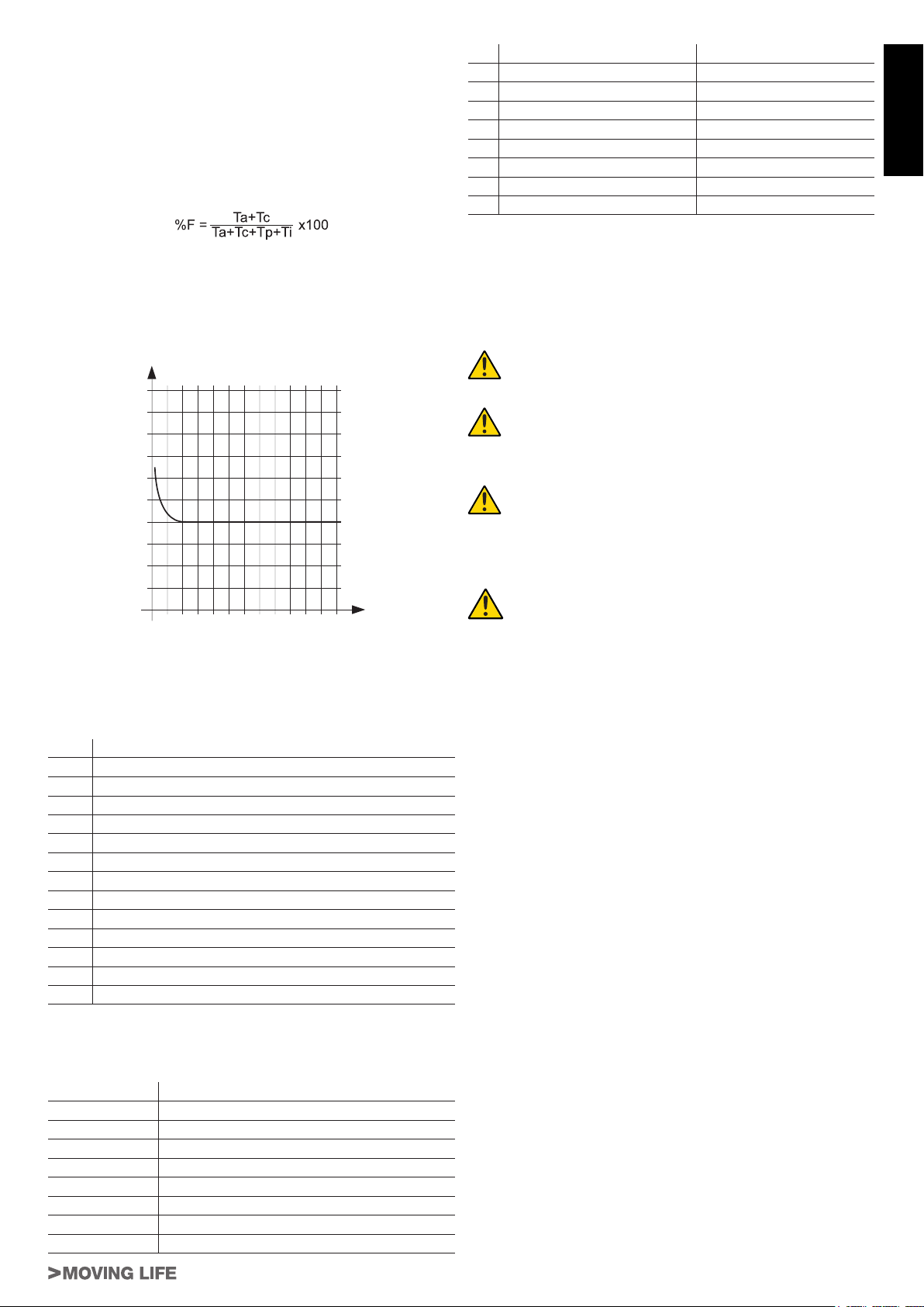
Per garantire il buon funzionamento è necessario operare nel campo di lavoro sotto la curva.
Importante: la curva è ottenuta alla temperatura di 15 °C.
L’esposizione all’irraggiamento solare diretto può determinare diminuzioni della frequenza d’utilizzo no al 20%.
Calcolo della frequenza d’utilizzo:
E’ la percentuale del tempo di lavoro effettivo (apertura + chiusura) rispetto al tempo totale del ciclo (apertura + chiusura + tempi
sosta).
La formula di calcolo è la seguente:
dove:
Ta = tempo di apertura
Tc = tempo di chiusura
Tp = tempo di pausa
Ti = tempo di intervallo tra un ciclo completo e l’altro
Percentuale
di lav. %
100
90
80
70
60
50
40
30
20
10
1 0
Tempo (h) Time (h) Zeit (Std.)
% Benutzungs-
% Duty cycle
frequenz
2 3 4 5 6 7 8 9 10 11 12
Temps (h)
% Fréquence
d’utilisation
% Frecuencia
% factor
de utilización
serviço
Tiempo (h) Tempo (h)
Rif. 230 V AC 12 V DC
a 3x1,5mm² 3x1,5mm²
b 2x0,5mm² 2x0,5mm²
c RG58 RG58
d 2x0,5mm² (TX) 2x0,5mm² (TX)
e 4x0,5mm² (RX) 4x0,5mm² (RX)
f* 3x0,5mm² 3x0,5mm²
g 2x0,5mm² 2x0,5mm²
h 2x0,5mm² 2x0,5mm²
* Se si installa anche l’art. P-300TSL, prevedere per il selettore a
chiave un cavo 5x0,5mm².
Note:
• se il cavo di alimentazione è più lungo di 30m occorre un cavo
con sezione maggiore, ad esempio 3x2,5mm² ed è necessaria
una messa a terra di sicurezza in prossimità dell’automazione.
Posizionare la centrale di comando (se esterna) nelle
immediate vicinanze dei motori.
Evitare che i cavi dei dispositivi ausiliari siano posizionati all’interno di condutture dove sono presenti altri
cavi che alimentano grossi carichi o lampade con starter elettronico.
Nel caso in cui vengano installati pulsanti di comando o spie di segnalazione all’interno di abitazioni o di
edici che distano parecchi metri dalla centrale stessa,
è consigliabile disaccoppiare il segnale tramite relay
onde evitare disturbi indotti.
3_ INSTALLAZIONE
L’installazione di T-ONE deve essere effettuata da personale qualicato, nel rispetto di leggi, norme e regolamenti e di quanto riportato nelle presenti istruzioni.
ITALIANO
2.2_ Impianto tipico
In gura 3 è riportato l’impianto tipico dell’automazione di un cancello di tipo scorrevole utilizzando T-ONE.
N° Descrizione
1 Selettore a chiave
2 Bordo primario sso (opzionale)
3 Fotocellule
4 Bordo primario mobile
5 Staffa di necorsa “Aperto”
6 Cremagliera
7 Bordo secondario sso (opzionale)
8 Lampeggiante con antenna incorporata
9 Motoriduttore
10 Staffa di necorsa “Chiuso”
11 Sistema wireless
12 Battenti a pavimento
13 Bordo secondario mobile (opzionale)
Cablaggio:
Nell’impianto tipico di gura 3 sono indicati anche i cavi necessari
per i collegamenti dei vari dispositivi; in tabella sono indicate le
caratteristiche dei cavi.
Collegamento Tipo cavo
a: Linea elettrica di alimentazione
b: Lampeggiante
c: antenna
d: Fotocellule (TX)
e: Fotocellule (RX)
f: Selettore a chiave
g: Bordo sensibile primario
h: Bordi mobili
T-ONE Series
3.1_ Veriche preliminari
Prima di procedere con l’installazione di T-ONE è necessario eseguire questi controlli:
• Vericare che tutto il materiale da utilizzare sia in ottimo stato,
adatto all’uso e conforme alle norme.
• Vericare che la struttura del cancello sia adatta ad essere automatizzata.
• Vericare che il peso dell’anta rientri nei limiti di impiego riportati nel capitolo “2.1 Limiti d’impiego”
• Vericare che in tutta la corsa del cancello, sia in chiusura che
in apertura, non ci siano punti con maggiore attrito.
• Vericare che non vi sia pericolo di deragliamento dell’anta e
che non ci siano rischi di uscita dalle guide
• Vericare la robustezza degli arresti meccanici di oltrecorsa
controllando che non vi siano deformazioni anche se l’anta dovesse sbattere con forza sull’arresto.
• Vericare che l’anta sia in equilibrio cioè non deve muoversi se
lasciata ferma in una qualsiasi posizione.
• Vericare che la zona di ssaggio del motoriduttore non sia
soggetta ad allagamenti; eventualmente prevedere il montaggio del motoriduttore adeguatamente sollevato da terra.
• Vericare che la zona di ssaggio del motoriduttore permetta lo
sblocco ed una manovra manuale facile e sicura.
• Vericare che i punti di ssaggio dei vari dispositivi siano in
zone protette da urti e le superci siano sufcientemente soli-
de.
• Evitare che le parti dell’automatismo possano venir immerse in
acqua o in altre sostanze liquide
• Non porre T-ONE vicino a amme o fonti di calore; in atmosfere
potenzialmente esplosive, particolarmente acide o saline; questo può danneggiare T-ONE ed essere causa di malfunzionamenti o situazioni di pericolo.
• Nel caso sia presente un porta di passaggio interna all’anta
oppure una porta sull’area di movimento dell’anta, occorre as-
sicurarsi che non intralci la normale corsa ed eventualmente
provvedere con un opportuno sistema di interblocco
• Collegare la centrale ad una linea di alimentazione elettrica dotata di messa a terra di sicurezza.
• La linea di alimentazione elettrica deve essere protetta da un
adeguato dispositivo magnetotermico e differenziale.
5
Page 6
3.2_ Installazione meccanica
Individuazione del sito:
• Scegliere una posizione analoga all’area tratteggiata di g. 4
nel caso si proceda al ssaggio diretto al suolo (predisporre
uno o più tubi per il passaggio dei cavi elettrici, 1 g. 4) se
questo è in calcestruzzo, oppure come in g. 5 quando c’è da
ITALIANO
realizzare lo scavo, g. 5A (chiusura destra) o g. 5B (chiusura
sinistra).
Preparazione della base:
• Scavare le fondazioni per almeno 15 cm. di profondità e bene
allargate. Prevedere una guaina protettiva per i cavi.
Fissaggio della contropiastra di fondazione (mod. 400CPO):
• Ultimato lo scavo preparare la contropiastra di fondazione piegando le zanche ricavate nella piastra dalla stessa parte dove
sono stati ricavati gli inserti (1 g.6) per il ssaggio del motoriduttore mediante viti. Ricoprire con calcestruzzo annegando le
zanche e lasciando liberi gli inserti per il ssaggio del motoriduttore; la contropiastra dovrà essere perfettamente piana ad 1
o 2 cm. dal livello del terreno e ad una distanza di 42 mm. circa
dal cancello (g. 6).
Fissaggio della contropiastra di fondazione (mod. 400CPOR):
• Assemblare la piastra di fondazione come da g.7.
• La piastra di fondazione deve essere posizionata come da
g.7A (chiusura destra) o g.7B (chiusura sinistra) per garantire il corretto ingranamento tra il pignone e la cremagliera.
• Eseguire un plinto di fondazione come da g.5 e murare la
piastra di fondazione prevedendo una o più guaine per il passaggio dei cavi elettrici. Vericare la perfetta orizzontalità della
piastra con una livella. Attendere che il cemento faccia presa.
• Predisporre i cavi elettrici per il collegamento con gli accessori
e l’alimentazione elettrica come da g.3.
Per effettuare agevolmente i collegamenti fare fuoriuscire i cavi
circa 30 cm dal foro della piastra di fondazione.
In alternativa si può utilizzare una contropiastra regolabile in altezza (P-550CPMR o P-550CPMR1 - g. 17) per la quale le zanche
sse devono essere saldate alla rotaia e successivamente bloccate con 4 tasselli da fondazione M12x120 (vedi g. 18). Fissare
quindi la contropiastra regolabile come indicato in g. 19.
In questo modo è possibile adattare il motoriduttore ad un impianto
preesistente; vanno rispettate le misure indicate in g. 18.
Fissaggio del motoriduttore (su contropiastra mod. 400CPO):
• Ancorare il motoriduttore con n° 4 viti M8x30 e relative rondelle, come indicato in g. 8.
• Passare tutti i cavi attraverso i fori ricavati sulla base della contropiastra di fondazione.
• Se la cremagliera è già presente, inserire n° 4 grani M8x30
(1 g. 8 - optionals) e n° 4 dadi M8 (2 g. 8 - optionals) per
regolare il pignone alla giusta altezza, lasciando 1÷2 mm di
gioco dalla cremagliera, vericando la perfetta orizzontalità del
motoriduttore con una livella.
Fissaggio del motoriduttore (su contropiastra mod. 400CPOR):
• Ancorare il motoriduttore alla contropiastra come indicato in g.
9, utilizzando n° 4 dadi M8 e n° 8 rondelle adeguate.
• Passare tutti i cavi attraverso i fori ricavati sulla base della contropiastra di fondazione.
• Se la cremagliera è già presente, agire sui dadi (1 g. 9) per
regolare il pignone alla giusta altezza, lasciando 1÷2 mm di
gioco dalla cremagliera, vericando la perfetta orizzontalità del
motoriduttore con una livella.
Fissaggio della cremagliera (mod. 400CN):
• Sbloccare il motoriduttore come indicato nel paragrafo
“SBLOCCO MANUALE”.
• Aprire completamente l’anta, appoggiare sul pignone il primo
tratto di cremagliera e vericare che l’inizio della cremagliera
corrisponda all’inizio dell’anta come in gura 10. Vericare che
tra pignone e cremagliera vi sia un gioco di 1÷2 mm.
• Appoggiato sul pignone il primo pezzo di cremagliera a livello,
segnare il punto di foratura sul cancello; forare Ø 4 mm ed avvitare la vite autolettante Ø 6,3 mm.
• Muovere manualmente il cancello, vericando che la cremagliera sia in appoggio sul pignone e ripetere le operazioni dal
punto precedente.
• Accostare un altro elemento di cremagliera al precedente utilizzando, per mettere in fase la dentatura dei due elementi, l'incastro a coda di rondine come indicato in g.10.
6
• Muovere manualmente il cancello e procedere nelle operazioni
di ssaggio come per il primo elemento, proseguendo no alla
copertura completa del cancello.
Importante rispettare le misure di installazione e la distanza tra dente dell’ingranaggio e dente cremagliera
come indicato nelle gg. 6 e 10.
Nota: la cremagliera deve scorrere sull’ingranaggio del
motoriduttore per l’intera larghezza del proprio dente
(g. 6).
Fissaggio della cremagliera (mod. 400CFZ12):
• Montare i tre nottolini lettati sull’elemento della cremagliera (A
g. 11) posizionandoli nella parte superiore dell’asola. In tale
modo il gioco sull’asola consentirà nel tempo le eventuali regolazioni.
• Portare manualmente l’anta in posizione di apertura.
• Appoggiare sul pignone il primo pezzo di cremagliera a livello e
saldare il nottolino lettato sul cancello come indicato in g. 11.
• Muovere manualmente il cancello, vericando che la cremagliera sia in appoggio sul pignone e saldare il secondo e il terzo
nottolino.
• Accostare un altro elemento di cremagliera al precedente utilizzando, per mettere in fase la dentatura dei due elementi, un
pezzo di cremagliera come indicato in g. 11.
• Muovere manualmente il cancello e saldare i tre nottolini lettati proseguendo no alla copertura completa del cancello.
Importante rispettare le misure di installazione e la distanza tra dente dell’ingranaggio e dente cremagliera
come indicato nelle gg. 9 e 11.
Nota: la cremagliera deve scorrere sull’ingranaggio del
motoriduttore per l’intera larghezza del proprio dente
(g. 9).
Fissaggio e regolazione pattini di necorsa (T-ONE5 / T-ONE8 / T-ONEXL):
• Fissare con i relativi grani le staffe di necorsa di “Apertura” e di
“Chiusura” ai lati estremi della cremagliera come in gura 10 e
11. Occorre considerare che quando intervengono i necorsa,
l’anta si muoverà per altri 2÷3 cm; è consigliabile quindi porre
le staffe di necorsa con opportuno margine sugli arresti mec-
canici.
È consigliato inoltre lubricare con un po’ d’olio il punto di contatto del pattino di necorsa con la molla, al
ne di facilitare lo scivolamento e di evitare lo schiacciamento di quest’ultima.
Nota: per una completa sicurezza si fa obbligo di installare, se non presenti, i fermi meccanici (battenti a pavimento) con tappo in gomma, come mostrato in g. 3.
Può vericarsi, per effetto o somma di diversi fattori
(dilatazione termica, condizioni climatiche, frequenza
di utilizzo, etc.), una variazione, nell’arco della giornata, del punto di arresto del cancello, sia per la fase
di apertura che per la fase di chiusura. Non è pertanto
possibile garantire che il cancello si fermi sempre nello
stesso punto.
3.3_ Versione con pignone a catena: Serie T-ONEC
Il portone può altresì essere motorizzato come indicato nella g.
12. Passare la catena come indicato in gura.
Nella g. 12 si riporta inoltre il tipo di catena richiesta (passo 1/2”
x 5/16”).
3.4_
Registrazione della frizione elettronica (T-ONE3B
e T-ONE5B), elettrica (T-ONE5, T-ONE8 e T-ONEXL)
ATTENZIONE: Vericare che il valore della forza d’impatto misurato nei punti previsti dalla norma EN 12445
sia inferiore a quanto indicato nella norma EN 12453.
• Tutti i motori della serie T-ONE sono dotati di encoder regolabile per il rilevamento degli ostacoli durante la corsa. Con l’
apposito potenziometro sulla scheda si può quindi impostare la
coppia massima di spinta.
3.5_ Installazione dei vari dispositivi
Effettuare l’installazione degli altri dispositivi previsti seguendo le
rispettive istruzioni. Vericare in gura 3 i dispositivi che possono
essere collegati a T-ONE.
T-ONE Series
Page 7
4_ COLLEGAMENTI ELETTRICI
Prima di operare, assicurarsi che il motoriduttore non
sia elettricamente alimentato.
• Per effettuare i collegamenti, togliere il carter dal motoriduttore,
passare i cavi di alimentazione attraverso i fori ricavati sulla
contropiastra di fondazione (quando questa sia in uso) e attraverso il corpo inferiore del motoriduttore, quindi predisporli
per il collegamento alla morsettiera della scheda di comando
alloggiata nel supporto componenti elettrici.
• Usare cavi di sezione minima di 2,5 mm² per i circuiti di potenza (T-ONE3B e T-ONE5B) e di 1,5 mm² (T-ONE5, T-ONE8 e
T-ONEXL), di 0,5 mm² per i circuiti di comando.
Per i collegamenti alle schede comando consultare i relativi libretti
di istruzione:
- K120M per T-ONE3B;
- K125M per T-ONE5B;
- K580M per T-ONE5, T-ONE8 e T-ONEXL.
5_ INSTALLAZIONE BATTERIA 12V (T-ONE5B)
Se si vuole dotare il proprio motoriduttore di una batteria per garantire il funzionamento in assenza di corrente, togliere il carter
e inserirla nella apposita sede (g. 13); quindi collegare i cavi di
alimentazione alle linguette.
6_ SBLOCCO MANUALE
In assenza di tensione di linea levare il coperchietto della serratura, inlare la apposita chiave e ruotare come indicato in g. 14.
Quindi, come in g. 15, tirare la leva verso l’esterno per ottenere la
gestione manuale del cancello.
7_ FINECORSA (T-ONE5 / T-ONE8 / T-ONEXL)
La serie T-ONE (230V AC) è studiata per fuzionare con dispositivo
di ne corsa elettro-meccanico a micro-switch.
I cavi sono collegati come in g. 16:
1= grigio (comune);
2= arancione (F.C. chiude - contatto N.C.);
3= rosso (F.C. apre - contatto N.C.);
4= grigio (comune).
Se, come rafgurato in fg. 16, quando l’ingranaggio ruota in senso
orario e la molla si sposta come indicato, la corsa non si ferma,
invertire la posizione dei li rosso ed arancione sulla morsettiera
della scheda di comando.
8_ VERIFICHE FINALI ED AVVIAMENTO
L’allacciamento dell’alimentazione a T-ONE deve essere eseguito da personale esperto, qualicato, in possesso dei requisiti richiesti e nel pieno rispetto di leggi,
norme e regolamenti.
Non appena viene fornita tensione a T-ONE è consigliabile fare
alcune semplici veriche:
1. Vericare che i leds sulla scheda di comando siano accesi.
2. Vericare che il motore non comandi il movimento del portone
e che il lampeggiante sia spento.
Se tutto questo non avviene occorre spegnere immediatamente l’alimentazione alla centrale e controllare
con maggiore attenzione i collegamenti elettrici.
Altre informazioni utili per la ricerca e la diagnosi dei guasti sono
presenti nel capitolo “7.6 Risoluzione dei problemi”.
Per gli altri parametri da impostare, apprendimento della corsa,
regolazione della frizione, rallentamento, regolazione tempo di
chiusura automatica, sensibilità rilevamento ostacoli etc., fare riferimento alle istruzioni delle schede elettroniche.
T-ONE Series
9_ COLLAUDO E MESSA IN SERVIZIO
Questa è la fase più importante nella realizzazione dell’automazione al ne di garantire la massima sicurezza. Il collaudo può essere
usato anche come verica periodica dei dispositivi che compongo-
no l’automatismo.
Il collaudo dell’intero impianto deve essere eseguito da
personale esperto e qualicato che deve farsi carico
delle prove richieste, in funzione del rischio presente e
di vericare il rispetto di quanto previsto da leggi, normative e regolamenti, ed in particolare tutti i requisiti
della norma EN12445 che stabilisce i metodi di prova
per la verica degli automatismi per cancelli.
9.1_ Collaudo
Ogni singolo componente dell’automatismo, ad esempio bordi
sensibili, fotocellule, arresto di emergenza, ecc. richiede una specica fase di collaudo; per questi dispositivi si dovranno eseguire
le procedure riportate nei rispettivi manuali istruzioni.
Per il collaudo di T-ONE eseguire la seguente sequenza di operazioni:
1. Vericare che sia stato rispettato rigorosamente tutto quanto
previsto nel presente manuale ed in particolare nel capitolo “1
Avvertenze”;
2. Utilizzando i dispositivi di comando o arresto previsti (selettore
a chiave, pulsanti di comando o trasmettitori radio), effettuare
delle prove di apertura, chiusura ed arresto del cancello e vericare che il comportamento corrisponda a quanto previsto.
3. Vericare uno ad uno il corretto funzionamento di tutti i dispositivi di sicurezza presenti nell’impianto (fotocellule, bordi sensibili, arresto di emergenza, ecc.);
4. Per la verica delle fotocellule ed in particolare che non vi siano
interferenze con altri dispositivi, passare un cilindro di diametro
5 cm e lunghezza 30 cm sull’asse ottico prima vicino al TX, poi
vicino all’RX e inne al centro tra i due e vericare che in tutti
i casi il dispositivo intervenga passando dallo stato di attivo a
quello di allarme e viceversa. Inne vericare che provochi nella centrale l’azione prevista; esempio: nella manovra di chiusu-
ra provoca l’inversione di movimento.
5. Se le situazioni pericolose provocate dal movimento dell’anta
sono state salvaguardate mediante la limitazione della forza
d’impatto si deve eseguire la misura della forza secondo quanto previsto dalla norma EN 12445. Se la regolazione della “Velocità” ed il controllo della “Forza Motore” vengono usati come
ausilio al sistema per la riduzione della forza d’impatto, provare
e trovare le regolazioni che offrono i migliori risultati.
9.2_ Messa in servizio
La messa in servizio può avvenire solo dopo aver eseguito con esito positivo tutte le fasi di collaudo di TONE e degli altri dispositivi presenti. E’ vietata la messa in servizio parziale o in situazioni “provvisorie”.
• Realizzare e conservare per almeno 10 anni il fascicolo tecnico dell’automazione che dovrà comprendere almeno: disegno
complessivo dell’automazione, schema dei collegamenti elettrici, analisi dei rischi e relative soluzioni adottate, dichiarazione di conformità del fabbricante di tutti i dispositivi utilizzati (per
T-ONE utilizzare la Dichiarazione CE di conformità allegata);
copia del manuale di istruzioni per l’uso e del piano di manutenzione dell’automazione.
• Apporre sul cancello una targhetta contenente almeno i seguenti dati: tipo di automazione, nome e indirizzo del costruttore (responsabile della “messa in servizio”), numero di matricola, anno di costruzione e marchio “CE”.
• Fissare in maniera permanente in prossimità del cancello un’etichetta o una targa con indicate le operazioni per lo sblocco e
la manovra manuale.
• Realizzare e consegnare al proprietario la dichiarazione di conformità dell’automazione.
• Realizzare e consegnare al proprietario il manuale di “Istruzioni
ed avvertenze per l’uso dell’automazione”.
• Realizzare e consegnare al proprietario il piano di manutenzione dell’automazione (che deve raccogliere tutte le prescrizioni
sulla manutenzione dei singoli dispositivi).
• Prima di mettere in servizio l’automatismo informare adegua-
tamente ed in forma scritta il proprietario (ad esempio sul ma-
nuale di istruzioni ed avvertenze per l’uso dell’automazione)
sui pericoli ed i rischi ancora presenti.
7
ITALIANO
Page 8

10_ USO
I motoriduttori della serie T-ONE sono stati progettati per movimentare cancelli a scorrimento orizzontale con ante di peso massimo di Kg. 300 (T-ONE3B), di Kg. 500 (T-ONE5B e T-ONE5), di
Kg. 800 (T-ONE8) e di Kg. 1200 (T-ONEXL).
ITALIANO
Si fa espresso divieto di utilizzare l’apparecchio per
scopi diversi o in circostanze diverse da quelle menzionate.
La centralina elettronica installata consente di selezionare il funzionamento:
automatico: un impulso di comando esegue l’apertura e la chiusura del cancello;
semiautomatico: un impulso di comando esegue l’apertura o la
chiusura del cancello;
In caso di mancanza di energia elettrica, il cancello può funzionare ugualmente grazie alla possibilità di gestione manuale, per
la quale è necessario agire sul dispositivo di sblocco manuale. I
modelli T-ONE3B e T-ONE5B, alimentabili con batterie tampone,
garantiscono il normale funzionamento dell’automazione anche in
caso di mancanza di tensione di rete.
Si ricorda che si è in presenza di un dispositivo automatico e alimentato con corrente, perciò nell’utilizzo devono essere usate le
dovute precauzioni. In particolare, si raccomanda di:
• non toccare l’apparecchio con mani bagnate e/o piedi bagnati
o nudi;
• togliere la corrente prima di aprire la scatola comandi e/o il
motoriduttore;
• non toccare il motore se non siete sicuri che sia raffreddato;
• mettere in movimento il cancello solo quando è completamente
visibile;
• tenersi fuori dal raggio di azione del cancello se questo è in
movimento: aspettare no a che non sia fermo;
• non lasciare che bambini o animali giochino in prossimità del
cancello;
• non lasciare che bambini o incapaci usino il telecomando o altri
dispositivi di azionamento;
• effettuare una manutenzione periodica;
• in caso di guasto, togliere l’alimentazione e gestire il cancello
manualmente solo se possibile e sicuro. Astenersi da ogni intervento e chiamare un tecnico autorizzato.
SI FA ESPRESSO DIVIETO DI LAVARE L’AUTOMAZIONE UTILIZZANDO IDROPULITRICI O DISPOSITIVI SIMILARI. È SEVERAMENTE VIETATO INDIRIZZARE GETTI
D’ACQUA DIRETTAMENTE SULL’AUTOMAZIONE.
11_ MANUTENZIONE
I motoriduttori della serie T-ONE necessitano di poca manutenzione. Tuttavia il loro buon funzionamento dipende anche dallo stato
del cancello: perciò descriveremo brevemente le operazioni da
fare per avere un cancello sempre efciente.
Attenzione: nessuna persona ad eccezione del manutentore, che deve essere un tecnico specializzato, deve
poter comandare il cancello automatico durante la manutenzione.
Si raccomanda perciò di togliere l’alimentazione di rete evitando
così anche il pericolo di shock elettrici. Se invece l’alimentazione
dovesse essere presente per talune veriche, si raccomanda di
controllare o disabilitare ogni dispositivo di comando (telecomandi,
pulsantiere etc..) ad eccezione del dispositivo usato dal manuten-
tore.
12_ ACCESSORI OPZIONALI
La gamma dei motori della serie T-ONE è completata dai seguenti
accessori opzionali:
• P-650ESE03 sblocco manuale esterno provvisto di blindino;
• P-400FCM necorsa magnetico.
13_ RUMOROSITÀ
Il rumore aereo prodotto dal motoriduttore in condizioni normali di
utilizzo è costante e non supera i 70 dB.
14_ DEMOLIZIONE
L’eliminazione dei materiali va fatta rispettando le norme vigenti.
Nel caso di demolizione dell’automazione non esistono particolari
pericoli o rischi derivanti dall’automazione stessa.
È opportuno, in caso di recupero dei materiali, che siano separati
per tipologia (parti elettriche - rame - alluminio - plastica - etc...).
15_ SMANTELLAMENTO
Nel caso l’automazione venga smontata per essere poi rimontata
in altro sito è necessario:
- togliere l’alimentazione e scollegare tutto l’impianto elettrico;
- rimuovere il motoriduttore dalla base di ssaggio;
- smontare tutti i componenti dell’impianto;
- nel caso alcuni componenti non possano essere rimossi o ri-
sultino danneggiati, provvedere alla loro sostituzione.
16_ MALFUNZIONAMENTO: CAUSE E RIMEDI
Il cancello non apre, il motore non gira.
- Vericare che fotocellule o coste sensibili non siano sporche,
impegnate o non allineate. Procedere di conseguenza.
- Vericare che l’apparecchiatura elettronica sia regolarmente
alimentata, controllare l’integrità dei fusibili.
- Mediante i leds di diagnosi della centralina (vedere le rispettive
istruzioni), controllare se le funzioni sono corrette. Individuare eventualmente la causa del difetto. Se i leds indicano che
persiste un comando di start, controllare che non vi siano radiocomandi, pulsanti di start o altri dispositivi che mantengono
attivato (chiuso) il contatto di start.
- Se la centralina non funziona, sostituirla.
Nel caso le condizioni sopra elencate diano esito negativo, sosti-
tuire il motoriduttore.
Il cancello non apre, il motore gira ma non avviene il movimento.
- Lo sblocco manuale è rimasto inserito. Ripristinare il funzionamento motorizzato.
- Controllare se il cancello è in battuta negli arresti meccanici di
necorsa. Sbloccare manualmente il cancello, muoverlo e ripristinare il funzionamento motorizzato. Controllare e correggere
la posizione dei pattini necorsa.
- Controllare che non vi siano difetti di assetto meccanico del
cancello.
Nel caso le condizioni sopra elencate diano esito negativo, sostituire il motoriduttore.
Manutenzione ordinaria
Ciascuna delle seguenti operazioni deve essere fatta quando se
ne avverte la necessità e comunque ogni 6 mesi per un uso domestico (circa 3000 cicli di lavoro) e ogni 2 mesi per un uso intensivo,
es. condominiale (sempre ogni 3000 cicli di lavoro).
Cancello
- Lubricare (con oliatore) le ruote di scorrimento del cancello;
- Vericare la pulizia e la tenuta della cremagliera;
Impianto di automazione
- Verica funzionamento dispositivi di sicurezza (fotocellule, costa pneumatica, limitatore di coppia, etc..);
Manutenzione straordinaria
Se dovessero rendersi necessari interventi non banali su parti meccaniche, si raccomanda la rimozione del motoriduttore per
consentire una riparazione in ofcina dai tecnici della casa madre
o da essa autorizzati.
8
T-ONE Series
Page 9

DICHIARAZIONE DI INCORPORAZIONE DEL COSTRUTTORE
(ai sensi della Direttiva Europea 2006/42/CE AlI. II.B)
Fabbricante: TAU S.r.l.
Indirizzo: Via E. Fermi, 43
36066 Sandrigo (Vi)
ITALIA
Dichiara sotto la propria responsabilità che il prodotto: Attuatore elettromeccanico
realizzato per il movimento automatico di: Cancelli Scorrevoli
per uso in ambiente: Residenziale / Condominiale
completo di: Centrale elettronica di controllo e radioricevente
ITALIANO
Modello: T-ONE
Tipo: T-ONE3B / T-ONE5B / T-ONE5 / T-ONE8 / T-ONEXL
Numero di serie: VEDI ETICHETTA ARGENTATA
Denominazione commerciale: AUTOMAZIONE PER CANCELLI SCORREVOLI
È realizzato per essere incorporato su una chiusura (cancello scorrevole) o per essere assemblato con altri dispositivi al ne di movimentare una tale chiusura per costituire una macchine ai sensi della Direttiva Macchine 2006/42/CE.
Dichiara inoltre che questo prodotto è conforme ai requisiti essenziali di sicurezza delle seguenti ulteriori direttive CEE:
- 2006/95/CE Direttiva Bassa Tensione
- 2004/108/CE Direttiva Compatibilità Elettromagnetica
ed, ove richiesto, alla Direttiva:
- 1999/5/CE Apparecchiature Radio e apparecchiature terminali di telecomunicazione
Dichiara inoltre che non è consentito mettere in servizio il macchinario no a che la macchina in cui sarà incorporato o di cui diverrà
componente sia stata identicata e ne sia stata dichiarata la conformità alle condizioni della Direttiva 2006/42/CE.
Si impegna a trasmettere, su richiesta adeguatamente motivata delle autorità nazionali, informazioni pertinenti sulle quasi-macchine.
Sandrigo, 14/11/2011
Il Rappresentante Legale
_________________________________________
Bruno Danieli
Nome e indirizzo della persona autorizzata a costituire la documentazione tecnica pertinente:
Loris Virgilio Danieli - via E. Fermi, 43 - 36066 Sandrigo (Vi) Italia
T-ONE Series
9
Page 10
1_ INSTALLATION WARNINGS
GENERAL SAFETY REQUIREMENTS
1) Carefully read all instructions before installation, as
they provide important instructions regarding the safety, installation, operation and maintenance. Incorrect
installation or use of the product may lead to serious
physical injury.
2) Never leave packaging materials (plastic, polystyrene etc.)
within the reach of children as they constitute a potential
hazard.
3) Keep the instructions in a safe place for future consultation.
4) This product has been designed and constructed exclu-
sively for the use specied in this documentation. Any other
ENGLISH
use not specied herein may impair product integrity and/or
constitute a hazard.
5) TAU declines all liability for improper use or use other than
as specied for this automation.
6) Never install the product in explosive atmospheres.
7) The mechanical elements must comply with the require-
ments as stated in the standards EN 12604 and EN 12605.
For non European member states, in addition to the national reference standards, the above-mentioned standards
must be observed to ensure an adequate level of safety.
8) TAU is not responsible for failure to observe Good Practice
in construction of the gates/doors to be power-operated,
nor any deformations occurring during use.
9) Considering the hazards that may occur during installation
and use of T-ONE, maximum safety is only ensured if the
product is installed in strict observance of current legislation,. standards and regulations. This chapter contains general warnings, while other important warnings are provided
in chapters “3.1 Preliminary checks” and “8. Testing and
commissioning”.
According to the most recent legislation, the installation of a power-operated gate or door must be in full
observance of the standards envisaged by European
Directive 2006/42/EC (Machinery Directive) and in
particular the standards: EN 12445; EN 12453 and EN
12635, which enable the declaration of presumed conformity.
10) Before installation, an assessment of the associated risks
must be made, including a list of the essential safety requirements as envisaged in Appendix I of the Machinery
Directive, specifying the relative solutions adopted. Note
that the risk assessment is one of the documents included
in the automation Technical documentation.
11) Check whether other devices are needed to complete the
T-ONE automation on the basis of the specic conditions
of use and dangers present; take into account all risks of
impact, crushing, shearing, dragging etc. and other hazards
in general.
12) Installation must be performed in compliance with the
standards EN 12453 and EN 12445.
13) Before performing any operations on the system, discon-
nect from the mains and detach the batteries.
14) On the automation power line, install a device for discon-
nection from the power mains with a gap between contacts
equal to or greater than 3 mm. Use of a 6A thermal magnetic circuit breaker with multi-pole switch is recommended.
15) Check upline of the system that there is a residual current
circuit breaker with a threshold of 0.03 A.
16) Ensure that the earthing system is to professional stand-
ards and connected to the metal section of the gate/door.
17) The automation is equipped with an intrinsic anti-crushing
safety device comprising a torque control. The trip threshold must in all cases be checked as stated in the standards
specied in point 12.
18) The safety devices (standard EN 12978) enable the protec-
tion of danger areas from risks associated with mechani-
cal movements such as crushing, dragging and shearing.
10
19) The use of at least one luminous indicator is recommended
for each system, as well as a warning notice xed suitably
to the frame structure, in addition to the devices specied in
point 18.
20) TAU declines all liability for the safety and efcient operation of the automation in the event of using system components not produced by TAU.
21) For maintenance, use exclusively original TAU parts.
22) Never modify components that are part of the automation
system.
23) The automation may only be used after completing the
commissioning procedure as specied in chapter 5 “Testing
and commissioning”.
24) The installer must provide all information regarding manual
operation of the system in the event of an emergency and
supply the system User with the “User Guide” enclosed with
the product.
25) Never allow children or other persons to stay in the vicinity
of the product during operation.
26) Keep all radio controls or other pulse supplier device out of
the reach of children to prevent inadvertent activation of the
automation.
27) Transit should only occur with the automation stationary.
28) The user must never attempt to repair or intervene directly
on the product; always contact qualied personnel for as-
sistance.
29) Before accessing internal terminals under the cover of TONE, disconnect all power circuits. If the disconnect device
is not in a visible location, afx a notice stating “CAUTION:
MAINTENANCE IN PROGRESS”.
30) Maintenance: at least every six months, make a general
check of the system, with special reference to the efciency
of the safety devices (including, when envisaged, the operator thrust force) and release mechanisms.
31) All actions not expressly envisaged in these instructions are
strictly prohibited.
All documentation related to the system should be kept inside
or in the immediate vicinity of the control unit.
2_ PRODUCT DESCRIPTION AND INTENDED USE
(g. 1)
T-ONE is an electromechanical gearmotor for the automatic movement of sliding gates for residential applications, and is equipped
with an electronic control unit with built-in receiver for radio control.
There are several versions available: 12V DC and 230V AC.
The irreversible system guarantees mechanical blocking of the
gate when the motor is not operating. A practical and safe release
system with personalised key enables manual movement of the
gate in the event of a malfunction or power failure.
The T-ONE operator has been designed and constructed to control vehicle access. Never use for other purposes.
1_ Gearmotor
2_ Electronic control unit
3_ Pinion
4_ Manual release
5_ Protection guard
2.1_ Product application limits and dimensions (g. 2)
The data regarding the performance of T-ONE3B, T-ONE5B, TONE5, T-ONE8 and T-ONEXL are stated in the chapter “TECHNICAL SPECIFICATIONS” and are the only values that ensure the
correct assessment for suitability of use.
In general the series T-ONE is able to automate gates with a weight
of up to 300Kg (T-ONE3B), 500 Kg (T-ONE5B and T-ONE5), 800
Kg (T-ONE8) and 1200 Kg (T-ONEXL).
Maximum operating curve:
This curve enables identication of the maximum operating time
(T) according to the frequency of use (F).
E.g.: The T-ONE5 gearmotor can operate without interruption at a
frequency of use of 40%.
T-ONE Series
Page 11

To guarantee optimal operation, the unit must operate within the
operating range below the curve.
Important: the curve is obtained at a temperature of 15 °C.
Exposure to direct sunlight may reduce the frequency of use by
up to 20%
Calculating the frequency of use:
This is the percentage of the effective operating time (opening and
closing) with respect to the total time of the cycle (opening + closing + pause time).
The calculation formula is as follows:
where:
Ta = Opening time
Tc = Closing time
Tp = Pause time
Ti = Interval time between one complete cycle and the next
Percentuale
di lav. %
100
90
80
70
60
50
40
30
20
10
1 0
Tempo (h) Time (h) Zeit (Std.)
% Benutzungs-
% Duty cycle
frequenz
2 3 4 5 6 7 8 9 10 11 12
Temps (h)
% Fréquence
d’utilisation
% Frecuencia
% factor
de utilización
serviço
Tiempo (h) Tempo (h)
Ref. 230 V AC 12 V DC
a 3x1,5mm² 3x1,5mm²
b 2x0,5mm² 2x0,5mm²
c RG58 RG58
d 2x0,5mm² (TX) 2x0,5mm² (TX)
e 4x0,5mm² (RX) 4x0,5mm² (RX)
f* 3x0,5mm² 3x0,5mm²
g 2x0,5mm² 2x0,5mm²
h 2x0,5mm² 2x0,5mm²
* If art. P-300TSL is also installed, envisage a cable 5x0.5 mm for
the key selector switch.
ENGLISH
Notes:
• If the power cable is longer than 30 m, a cable with a larger
cross-section is required (3 x 2.5 mm2) and safety earthing is
necessary in the vicinity of the automation.
Place the control unit (external versions) in the immediate vicinity of the motors.
Be careful not to run cables for auxiliary devices inside raceways housing other cables supplying power
to large loads or lights with electronic starters.
In the event control pushbuttons or indicator lights are
installed inside homes or ofces several metres from
the actual control unit, it is advisable to decouple the
signal by means of a relay in order to avoid induced
interference.
3_ INSTALLATION
T-ONE must be installed by qualied personnel, in
compliance with local legislation, standards, regulations and these instructions.
2.2_ Typical system
Figure 3 shows a typical automation system for a sliding gate using T-ONE.
N° Description
1 Key-operated selector switch
2 Fixed primary edge (optional)
3 Photocells
4 Mobile primary edge
5 “Open” limit switch bracket
6 Rack
7 Secondary xed edge (optional)
8 Flashing light with built-in aerial
9 Gearmotor
10 “Closed” limit switch bracket
11 Wireless system
12 Floor-mounted end stops
13 Secondary mobile edge (optional)
Wiring:
The typical system in gure 3 also shows the cables required for
connecting the various devices; the table species the cable specications.
Connection Cable type
a: Mains power line
b: Flashing light
c: Antenna
d: Photocells (TX)
e: Photocells (RX)
f: Key-operated selector switch
g: Primary sensitive edge
h: Mobile edges
T-ONE Series
3.1_ Preliminary checks
Before installing T-ONE, perform the following checks:
• Ensure that all material used is in perfect condition, suitable for
use and compliant with standards.
• Ensure that the gate structure is suitable for automation.
• Ensure that the weight of the leaf is within the application limits
as specied in paragraph 2.1 “Application limits”
• Ensure that there are no points of increased friction at any point
of gate travel, both in opening and closing.
• Ensure that there is no risk of gate derailing or risks of exit from
the tracks
• Check resistance of the mechanical overtravel stops, ensuring
there are no deformations even if the gate impact is strong on
stopping.
• Check that the leaf is balanced and therefore does not move if
left stationary in any position.
• Make sure that the xing zone is not subject to ooding. If necessary, mount the gearmotor raised from the ground.
• Ensure that the gearmotor xing zone enables safe and easy
manual movement and release.
• Ensure that the selected surfaces for installation of the various
devices are solid, protected from the risk of impact and guarantee a stable xture.
• Ensure that parts of the automation cannot come into contact
with water or other liquids
• Never place T-ONE in the vicinity of ames or heat sources; in
potentially explosive, particularly acid or saline atmospheres,
this may damage T-ONE and cause malfunctions or hazardous
situations.
• If the gate leaf incorporates a pedestrian access door or if this
door is positioned in the gate movement area, ensure that this
does not prevent normal gate travel; if necessary install a compatible interlock system
• Connect the control unit to an electric power line equipped with
an earthing system.
• The mains power line must be protected by an adequate thermal magnetic and residual current circuit breaker device.
11
Page 12
3.2_ Mechanical installation
Site location:
• Choose a position similar to the outlined area in g. 4 when
xing the unit directly to the ground (lay one or two conduits
for routing electrical wiring, 1 g. 4) if in concrete, or as shown
in g. 5 when an excavation is required, g. 5A (right-hand closure) or g. 5B (left-hand closure).
Base preparation:
• Dig the foundations to a depth of at least 15 cm with sufcient
width. Fit a protective sheath for routing the electric cables.
Fixing the foundation plate assembly (model 400CPO):
• On completion of excavations, prepare the foundation plate as-
ENGLISH
sembly by bending the anchor elements in the plate on the
same section mounting the inserts (1, g. 6) for xing the gearmotor by means of screws. Embed the anchor elements in concrete while leaving the inserts exposed for gearmotor xture;
the foundation plate assembly must be perfectly at at 1 or 2
cm from ground level and at a distance of approx. 42 mm from
the gate (g. 6).
Fixing the foundation plate assembly (model 400CPOR):
• Assemble the foundation plate as shown in g. 7.
• The foundation plate must be positioned as shown in g.7A
(right-hand closure) or g.7B (left-hand closure) to guarantee
correct meshing of the pinion and rack.
• Make a foundation plinth as shown in g. 5 and install the foundation plate, envisaging one or more conduit sheaths for routing the electric cables. Check perfect positioning of the plate
using a spirit level. Wait for the cement to set.
• Lay the electric cables for connection to the accessories and
electrical mains as shown in g. 3.
To facilitate connections, leave an excess length of cables of approx. 30 cm from the hole in the foundation plate.
Alternatively, a height adjustable base plate (P-550CPMR or P-
550CPMR1 - g. 17) can be used. In this case the xed ties must
be welded to the track and after locked with 4 expansion bold
M12x120 (see g. 18). The adjustable base plate is then secured
as indicated in g. 19.
In this way the gearmotor can be adapted to an already existing
system; the measurements indicated in g. 18 must be respected.
Fixing the gearmotor (on foundation plate assembly model
400CPO):
• Anchor the gearmotor using 4 screws M8x30 and relative
washers, as shown in g. 8.
• Pass all cables through the holes on the base of the foundation
plate assembly.
• If the rack is already present, insert the 4 stud bolts M8x30 (1
g. 8 - optional) and 4 nuts M8 (2 g. 8 - optional) to adjust the
pinion at the correct height, leaving 1÷2 mm of play from the
rack, checking perfect levelling of the gearmotor with a spirit
level.
Fixing the gearmotor (on foundation plate assembly model
400CPOR):
• Anchor the gearmotor to the foundation plate assembly as
shown in g. 9, using 4 nuts M8 and 8 washers.
• Pass all cables through the holes on the base of the foundation
plate assembly.
• If the rack is already present, adjust nuts (1 g. 9) to set the pinion at the correct height, leaving 1÷2 mm of play from the rack,
checking perfect levelling of the gearmotor with a spirit level.
Fixing the rack (model 400CN):
• Release the gearmotor as described in the paragraph “MANUAL RELEASE”.
• Open the leaf completely, position the rst section of the rack
aligned with the edge of the gate and check that the start of the
rack corresponds to the start of the leaf as shown in gure 10.
Check that there is a clearance of 1÷2 mm between the pinion
and rack.
• After positioning the rst section of the rack aligned with the
edge of the gate, mark the drilling point on the gate, drill a Ø 4
mm hole and insert the self-tapping screw Ø 6,3 mm.
12
• Manually move the gate, checking that the rack is positioned
on the pinion and repeat the operations described in the previ-
ous point.
• Move another rack element up against the previous one, using
the dovetail connection to mesh the teeth of the two elements
as shown in g. 10.
• Manually move the gate and proceed with the xing operations
as per the rst element, through to complete coverage of the
gate.
It is very important to observe the installation measurements and distance between the gear teeth and rack
teeth as shown in gures 6 and 10.
Note: the rack must slide on the gear of the gearmotor
throughout the entire length of its tooth (g. 6).
Fixing the rack (model 400CFZ12):
• Mount the three threaded pawls on the rack element (A g.
11) positioning them on the upper section of the slot. This will
ensure clearance on the slot for future adjustments when required.
• Manually move the leaf to the opening position.
• Position the rst section of the rack aligned with the edge of the
gate, and weld the threaded pawl onto the gate as shown in g.
11.
• Manually move the gate, checking that the rack is positioned
on the pinion and weld the second and third pawl.
• Move another rack element up against the previous one, using
a rack element to mesh the teeth of the two elements as shown
in g. 11.
• Manually move the gate and weld the three threaded pawls
through to complete coverage of the gate.
It is very important to observe the installation measurements and distance between the gear teeth and rack
teeth as shown in gures. 9 and 11.
Note: the rack must slide on the gear of the gearmotor
throughout the entire length of its tooth (g. 9).
Fixing and adjusting the limit switch pads (T-ONE5 / T-ONE8 / T-ONEXL):
• With the relative stud bolts, x the “opening” and “closing” limit
switch brackets at the ends of the rack as shown in gure 10
and 11. Take into consideration that when the limit switches
trip, the leaf continues to move by a further 2÷3 cm; therefore
the limit switch brackets should be positioned with a suitable
margin on the mechanical stops.
It is also recommended to slightly lubricate the point
of contact of the limit switch pad with the spring, to
facilitate sliding and prevent compression of the latter.
Note: to ensure complete safety, mechanical stops
(oor-mounted end stops), if not already present, with
rubber caps MUST be tted, as shown in g. 3.
A single factor or combination of factors (thermal expansion, climate, frequency of use, etc.) may result in
the position the gate stops in changing over the course
of the day, both when opening and when closing. Consequently, we cannot guarantee that the gate will always stop in the same position.
3.3_ Version with chain pinion: T-ONEC Series
The door can also be power-operated as shown in g. 12. Pass the
chain as shown in g.
Fig. 12 also shows the type of chain required (pitch 1/2” x 5/16”).
3.4_
Adjustment of the electronic clutch (T-ONE3B, T-ONE5B),
and electric clutch (T-ONE5, T-ONE8 and T-ONEXL)
IMPORTANT: Ensure that the impact force measured at
the points as envisaged by the standard EN 12445 is
less than the value specied in standard EN 12453.
• All motors in the T-ONE series are equipped with a settable encoder for obstacle detection during travel. The maximum thrust
torque can then be set by means of the relative potentiometer
on the card.
3.5_ Installation of various devices
To install the other devices envisaged, refer to the relevant instructions. Check in gure 3 the devices that can be connected to TONE.
T-ONE Series
Page 13
4_ ELECTRICAL CONNECTIONS
Before proceeding, ensure that the gearmotor is not
connected to the electrical mains.
• To make the connections, remove the cover from the gearmotor, route the power cables through the holes on the foundation plate assembly (if used) and through the lower body of the
gearmotor, then prepare them for connection to the terminal
board of the control card housed in the electrical components
support.
• Use cables with a minimum section of 2.5 mm² for the power
circuits (T-ONE3B and T-ONE5B) and 1.5 mm² (T-ONE5, TONE8 and T-ONEXL), 0.5 mm² for the control circuits.
For connections to the control cards consult the relative instruction
booklets:
- K120M for T-ONE3B;
- K125M for T-ONE5B;
- K580M for T-ONE5, T-ONE8 and T-ONEXL.
5_ 12V BATTERY INSTALLATION (T-ONE5B)
If a battery is to be tted on the gearmotor to guarantee operation
in the event of a power failure, remove the cover and insert it in the
relative seat (g. 13); then connect the power cables to the tabs.
6_ MANUAL RELEASE
In the event of a power failure, raise the cover from the lock, insert
the relative key and turn as shown in g. 14.
Then, as shown in g. 15, pull the lever outwards to enable manual
movement of the gate.
7_ LIMIT SWITCH (T-ONE5 / T-ONE8 / T-ONEXL)
The series T-ONE (230 Vac) has been designed to operate with an
electro-mechanical micro-switch type limiter.
The cables are connected as shown in g. 16:
1= grey (common);
2= orange (F.C. close - NC contact);
3= red (F.C. Open - NC contact);
4= grey (common).
As shown in g. 16, when the gear rotates clockwise and the spring
moves as shown, if gate travel does not stop, invert the position of
the red and orange wires on the terminal board of the control card.
8_ FINAL CHECKS AND START-UP
T-ONE must be connected to the power mains by
skilled and qualied personnel, in possession of all
requirements for full compliance with all legal provisions, standards and regulations.
Immediately after powering up T-ONE, perform a number of simple
checks:
1. Ensure that the leds on the control card are lit.
2. Ensure that the motor does not activate any gate movement
and that the ashing light is off.
If this is not so, disconnect the control unit from the
power supply immediately and check the electrical
connections carefully.
Other useful information for troubleshooting can be found in chapter 7.6 “Troubleshooting”.
For other parameter settings, such as gate travel learning, clutch
adjustment, deceleration, automatic closure time, obstacle detec-
tion sensitivity etc., refer to the instructions of the electronic cards.
9_ TESTING AND COMMISSIONING
This is the most important phase of automation set-up to ensure
maximum system safety. The test can also be performed as a periodic check of automation devices.
Testing of the entire system must be performed by
skilled and qualied personnel, who are responsible
for the tests required to verify the solutions adopted
according to the risks present, and for ensuring observance of all legal provisions, standards and regulations, with particular reference to all requirements of
the standard EN12445 which establishes the test methods for testing automations for power-operated gates.
T-ONE Series
9.1_ Testing
Each automation component, such as sensitive edges, photocells,
emergency stop, etc., requires a specic testing phase; for these
devices take care to follow the procedures specied in the respec-
tive instruction manual.
To test T-ONE, perform the following sequence of operations:
Ensure that all specications in this manual, and in particular chap-
ter “1 WARNINGS” have been strictly observed;
2. Using the control or stop devices envisaged (key-operated
selector switch, control pushbuttons, radio transmitters, etc.)
perform gate opening and closing tests, ensuring that the leaf
movement corresponds to specications.
3. Check operation of all system safety devices one at a time
(photocells, sensitive edges, emergency stop etc.);
4. To test photocells and in particular that there is no interference
with other devices, pass a cylinder (diameter 5 cm, length 30
cm) through the optic axis joining the pair of photocells, rst
close to the TX and then the RX and then mid-way between
the two. Ensure that in all cases the device engages, changing from the active status to alarm status and vice versa. Also
check that the envisaged action is generated in the control unit,
for example: that during the Closing manoeuvre, the door inverts the current movement.
5. If hazardous situations generated by the moving leafs are protected by means of impact force limitation, measure the force
as specied in the standard EN 12445. If the settings “speed”
and “gearmotor force” control are used as an auxiliary function
with the system for reduction of impact force, test and identify
the setting that obtains the best results.
9.2_ Commissioning
Commissioning can only be performed after positive
results of all test phases on T-ONE and other devices
present. Partial or “makeshift” commissioning is strictly prohibited.
• Prepare the automation technical documentation (to be conserved for at least 10 years), which must contain the following documents: an overall layout diagram of the automation,
electrical wiring diagram, risk assessment and relative solutions adopted, manufacturer’s declaration of conformity for all
devices used (for T-ONE use the CE declaration of conformity
enclosed) copy of instruction manual for operation and the automation maintenance schedule.
• Afx a dataplate on the gate, specifying at least the following
data: type of automation, name and address of manufacturer
(responsible for commissioning), serial number, year of construction and CE mark.
• Permanently x a label or plate in the vicinity of the gate, stating the procedures for release and manual manoeuvres.
• Compile the automation declaration of conformity and deliver
to the owner.
• Compile the manual “Instructions and warnings for automation
operation” and deliver to the owner.
• Prepare the automation maintenance schedule (including all
instructions for the maintenance of individual devices) and deliver to the owner.
• Before commissioning the automation, ensure that the owner is
adequately informed in writing of all associated risks and hazards (for example of the manual of instructions and warnings
for automation operation).
10_ OPERATION
The gearmotors in the series T-ONE have been designed to move
horizontal sliding gates with leafs of a maximum weight of 300 kg
(T-ONE3B), 500 kg (T-ONE5B and T-ONE5), 800 kg (T-ONE8)
and 1200 Kg (T-ONEXL).
Use of the device for other purposes or in other circumstances than as specied is strictly prohibited.
The electronic control unit installed enables selection of the operating mode:
automatic: a control pulse activates gate opening and closing;
semiautomatic: a control pulse activates gate opening or closing;
In the event of a power failure, the gate can still operate thanks
to the option of manual control, possible by means of the manual
release device.
13
ENGLISH
Page 14

The models T-ONE3B and T-ONE5B, with the optionals batteries
power supply guarantee normal automation operation also in the
event of a power failure.
Note that this is an automatic device and mains powered, and
therefore when used the due precautions must be taken. The following in particular is recommended:
• Never touch the device with wet hands and/or wet or bare feet;
• Disconnect the power supply before opening the controls box
and/or gearmotor;
• Never touch the motor before ensuring it is completely cool;
• Only move the gate when it is completely visible;
• Keep away from the operating range of the gate when in movement: wait until it is stationary;
• never allow children or animals to play in the vicinity of the
ENGLISH
gate;
• never allow children or unskilled persons to use the remote
control or other activation devices;
• Perform periodic maintenance;
• In the event of a fault, disconnect the power supply and only
move the gate manually when possible and in safety. Do not
intervene on the gate; call an authorised technician for assis-
tance.
CLEANING OF THE AUTOMATION WITH WATER JETS
OR SIMILAR DEVICES IS STRICTLY PROHIBITED. NEVER DIRECT WATER JETS DIRECTLY ONTO THE AUTOMATION.
11_ MAINTENANCE
The gearmotors in the T-ONE series are low maintenance products. However efcient operation also depends on the condition of
the gate: Therefore a number of simple operations are described
below to maintain gate efciency.
Caution: No person other than the maintenance engineer (who must be a specialised technician) must be
allowed to operate the automatic gate during maintenance.
Therefore disconnect the device from the power mains to avoid the
risk of electric shock. However, if the power supply is required for a
number of checks, ensure that the control devices are controlled or
disabled (remote controls, pushbutton panels etc.) with the exception of the device used by the maintenance engineer.
Routine maintenance
Each of the following operations must be performed when deemed
necessary and in any event every 6 months in the case of domestic
use (approx. 3000 work cycles) and every 2 months in the case of
intensive use, e.g. apartment block (every 3000 work cycles).
Gate
- Lubricate (with a grease pump) the gate sliding wheels;
- Check the condition and stability of the rack;
Automation system
- Check operation of the safety devices (photocells, pneumatic
edge, torque limiter, etc..);
14_ SCRAPPING
All materials must be disposed of in observance of current standards.
If the automation is to be scrapped there are no particular dangers
or risks associated with the automation itself.
In the case of material recovery, separate components according
to the waste category (electrical parts - copper - aluminium - plastic, etc.).
15_ DISASSEMBLY
If the automation is disassembled for subsequent re-assembly in
another site:
- Disconnect the power supply and the entire electrical system;
- Remove the gearmotor from the xing base;
- Disassemble all system components;
- If some components cannot be removed or are damaged, re-
place.
16_ MALFUNCTIONS TROUBLESHOOTING
The gate does not open, the motor does not work.
- Check that the photocells or sensitive edges are not dirty, engaged or misaligned. Proceed according to the case in hand
- Check that the electrical equipment is powered correctly, check
all fuses.
- Check that all functions are correct via the control unit diagnostic leds (see relative instructions). Locate the cause of the fault.
If the leds indicate that a start command persists, check that
there are no radio controls, start pushbuttons or other devices
that keep the start contact activated (closed).
- If the control unit does not work, replace.
If results are negative after the above proposed solutions, replace
the gearmotor.
The gate does not open, the motor turns but there is no movement.
- The manual release is still engaged. Restore power operated
functions.
- Check that the gate is up against the mechanical limit stops.
Manually release the gate, move it and restore power-operated functions. Check and correct the position of the limitswitch
pads.
- Check that there are no defects in mechanical set-up of the
gate.
If results are negative after the above proposed solutions, replace
the gearmotor.
Special maintenance
If more complex operations are required on mechanical parts, the
gearmotor should be removed to enable repairs in the manufacturer’s workshop by technicians or other authorised centre.
12_ OPTIONAL ACCESSORIES
The range of T-ONE motors can be completed with the following
optional accessories:
• P-650ESE03 external manual release with armour-plated
case;
• P-400FCM magnetic limit switch.
13_ NOISE LEVELS
Airborne noise generated by the gearmotor in normal operating
conditions is constant and does not exceed 70 dB.
14
T-ONE Series
Page 15

MANUFACTURER’S DECLARATION OF INCORPORATION
(in accordance with European Directive 2006/42/EC App. II.B)
Manufacturer: TAU S.r.l.
Address: Via E. Fermi, 43
36066 Sandrigo (Vi)
ITA LY
Declares under its sole responsibility, that the product: Electromechanical actuator
designed for automatic movement of: Sliding Gates
for use in a: Residential / Communities
complete with: Electronic control unit and radioreceiver
ENGLISH
Model: T-ONE
Type: T-ONE3B / T-ONE5B / T-ONE5 / T-ONE8 / T-ONEXL
Serial number: SEE SILVER LABEL
Commercial name: AUTOMATION FOR SLIDING GATES
Has been produced for incorporation on an access point (sliding gate) of for assembly with other devices used to move such an access
point, to constitute a machine in accordance with the Machinery Directive 2006/42/EC.
Also declares that this product complies with the essential safety requirements of the following EEC directives:
- 2006/95/EC Low Voltage Directive
- 2004/108/EC Electromagnetic Compatibility Directive
and, where required, with the Directive:
- 1999/5/CE Radio equipment and telecommunications terminal equipment
Also declares that it is not permitted to start up the machine until the machine in which it is incorporated or of which it will be a component has been identied with the relative declaration of conformity with the provisions of Directive 2006/42/EC.
The manufacturer undertakes to provide, on sufciently motivated request by national authorities, all information pertinent to the quasimachinery.
Sandrigo, 14/11/2011
Legal Representative
_________________________________________
Bruno Danieli
Name and address of person authorised to draw up all pertinent technical documentation:
Loris Virgilio Danieli - via E. Fermi, 43 - 36066 Sandrigo (Vi) Italy
T-ONE Series
15
Page 16

1_ HINWEISE FÜR DEN INSTALLATEUR
ALLGEMEINE PFLICHTEN BEZÜGLICH DER SICHERHEIT
1) Lesen Sie vor der Installation genau die Anweisungen,
da sie wichtige Hinweise bezüglich der Sicherheit, der
Installation, der Bedienung sowie der Wartung enthalten. Eine falsche Installation oder eine falsche Anwendung des Produkts kann zu schweren Verletzungen
führen.
2) Das Verpackungsmaterial (Kunststoff, Polystyrol usw.) darf
nicht in der Reichweite von Kindern aufbewahrt werden, da
es eine mögliche Gefahrenquelle darstellt.
3) Die Anleitungen für einen späteren Bedarf aufbewahren.
4) Dieses Produkt wurde ausschließlich für den in diesen Un-
terlagen angegebenen Zweck entwickelt und gebaut. Jede
andere nicht ausdrücklich angegebene Nutzung könnte die
Unversehrtheit des Produkts beeinträchtigen und/oder eine
Gefahrenquelle darstellen.
5) TAU lehnt jede Verantwortung für einen unsachgemäßen
oder nicht den Angaben entsprechenden Gebrauch der Automatisierung ab.
6) Das Produkt nicht in EX-gefährdeter Atmosphäre oder Um-
DEUTSCH
gebung installieren.
7) Die mechanischen Bauteile müssen mit den Vorschriften
der Norm EN 12604 und EN 12605 übereinstimmen. In außereuropäischen Ländern müssen außer den nationalen
Vorschriften auch die oben genannten Normen befolgt werden, um eine ausreichende Sicherheitsstufe zu erreichen.
8) TAU übernimmt keinerlei Haftung im Falle von nicht fachge-
rechter Konstruktion der Toröffner oder im Falle von Verformungen derselben während des Gebrauchs.
9) Unter Berücksichtigung der Gefahren, die bei der Instal-
lation und Bedienung von T-ONE auftreten können, muss
die Installation zum Erhalt größter Sicherheit unter voller
Einhaltung von Gesetzen, Vorschriften und Verordnungen
erfolgen. In diesem Kapitel sind Hinweise allgemeiner Art
gegeben; weitere wichtige Hinweise benden sich in den
Kapiteln “3.1 Vorprüfungen”; “8 Abnahme und Inbetriebsetzung”.
ACHTUNG: nach der neuesten europäischen Gesetzgebung, gehört die Ausführung einer automatischen
Tür oder eines automatischen Tors zu den Verordnungen der Richtlinie 2006/42/EG (Maschinenrichtlinie)
und insbesondere zu den Vorschriften: EN 12445; EN
12453 und EN 12635, die es erlauben, die vermutliche
Konformität zu erklären.
10) Vor der Installation ist die Risikoanalyse auszuführen, wel-
che die Liste der wesentlichen Sicherheitsanforderungen,
vorgesehen in Anlage I der Maschinenrichtlinie, einschließen und die jeweiligen, angewendeten Lösungen angeben
muss. Es wird daran erinnert, dass die Risikoanalyse eine
der Unterlagen ist, die Bestandteil der “Technischen Dokumentation“ der Automatisierung sind.
11) Je nach Einsatzbedingungen und vorhandenen Gefahren
prüfen, ob weitere Vorrichtungen erforderlich sind, um die
Automatisierung mit T-ONE zu vervollständigen; berücksichtigt werden müssen zum Beispiel Aufprall-, Quetsch-,
Schnitt- und Mitnehmgefahr usw. und sonstige Gefahren
allgemein.
12) Die Installation muss bei Einhaltung der Normen EN 12453
und EN 12445 vorgenommen werden.
13) Vor der Ausführung beliebiger Arbeiten an der Anlage die
Stromspeisung entfernen und die Batterien abtrennen.
14) Im Speisungsnetz der Automatisierung einen allpoligen
Schalter mit einer Öffnungsdistanz der Kontakte gleich
oder über 3 mm vorsehen. Wir empfehlen, einen 6A-Magnetthermoschalter mit einer allpoligen Unterbrechung zu
verwenden.
15) Prüfen, ob hinter der Anlage ein Differenzialschalter mit
max. 0,03 A vorliegt.
16) Prüfen, ob die Erdung fachgerecht ausgeführt wurde und
die Metallteile des Toröffners daran anschließen.
16
17) Die Automatisierung verfügt über einen eigenleitenden
Quetschschutz, der aus einer Drehmomentkontrolle besteht. Es ist auf jeden Fall notwendig, den Grenzwert gemäß den Normen des Punkts 12 zu prüfen.
18) Die Sicherheitsvorrichtungen (Norm EN 12978) ermöglichen den Schutz eventueller Gefahrenbereiche vor me-
chanischen Bewegungsrisiken, wie z.B. Einquetschen,
Mitziehen, Schneiden.
19) Für jede Anlage sind die Verwendung mindestens einer
Leuchtanzeige und eines Hinweisschilds, das am Rahmen
befestigt wird, sowie die Vorrichtungen laut Punkt 18 empfehlenswert.
20) TAU lehnt jede Haftung hinsichtlich der Sicherheit und der
Funktionstüchtigkeit der Automatisierung ab, falls nicht von
TAU hergestellte Anlagenteile verwendet werden.
21) Zur Instandhaltung ausschließlich TAU-Originalersatzteile
verwenden.
22) Keine Änderung an Bestandteilen des Automatisierungssystems ausführen.
23) Die Automatisierung darf erst verwendet werden, nachdem
die Inbetriebsetzung ausgeführt wurde, wie in Punkt “5 Abnahme und Inbetriebsetzung“ vorgesehen.
24) Der Installateur muss alle Informationen bezüglich des manuellen Betriebs des Systems im Notfall weitergeben und
dem Anwender der Anlage die dem Produkt beigelegte „Bedienungsanleitung“ aushändigen.
25) Kindern oder anderen Personen nicht erlauben, während
des Betriebs in der Nähe des Produkts zu bleiben.
26) Fernsteuerungen oder andere Impulsgeber außerhalb der
Reichweite von Kindern aufbewahren, um zu vermeiden,
dass die Automatisierung ungewollt betätigt wird.
27) Der Durchgang darf nur bei stehender Automatisierung erfolgen.
28) Der Anwender darf keine Reparatur oder direkte Eingriffe
vornehmen und muss sich hierzu an qualiziertes Personal
wenden.
29) Vor dem Zugriff auf die Klemmen im Deckel von T-ONE,
alle Kreisläufe der Speisung abtrennen; falls die Abtrennvorrichtung nicht sichtbar ist, ein Schild mit der Aufschrift
:“ACHTUNG – WARTUNG IM GANG” anbringen.
30) Wartung: Mindestes alle sechs Monate die Funktionstüchtigkeit der Anlage prüfen, mit besonderer Beachtung der
Efzienz der Sicherheitsvorrichtungen (einschließlich der
Schubkraft der Automatisierung, wo vorhanden) und der
Entriegelungsvorrichtungen.
31) Alles nicht ausdrücklich in diesen Anweisungen vorgesehene ist unzulässig.
Wir empfehlen, die ganzen Unterlagen bezüglich der Anlage
innerhalb oder in der Nähe des Steuergeräts aufzubewahren.
2_
PRODUKTBESCHREIBUNG UND EINSATZ (Abb. 1)
T-ONE ist ein elektromechanischer Toröffner für die automatische
Bewegung von Schiebetoren an Wohngebäuden; er verfügt über
eine elektronische Steuerung und einen Empfänger für Funksteuerungen.
Die Automatisierung ist in mehreren Ausführungen erhältlich: mit
12V DC und mit 230V AC.
Das selbsthemmende System garantiert die mechanische Sperre
des Torügels, wenn der Antrieb nicht in Betrieb ist. Ein bequemes
und sicheres Entriegelungssystem mit individuellem Schlüssel ermöglicht die Bewegung des Tors im Falle einer Störung oder bei
Stromausfall von Hand.
Die Automatisierung T-ONE wurde zur Kontrolle des
Fahrzeugszugangs entwickelt und gebaut. Jede andere
Verwendung vermeiden.
1_ Toröffner
2_ Elektronische Steuerung
3_ Ritzel
4_ Handentriegelung
5_ Schutzgehäuse
T-ONE Series
Page 17
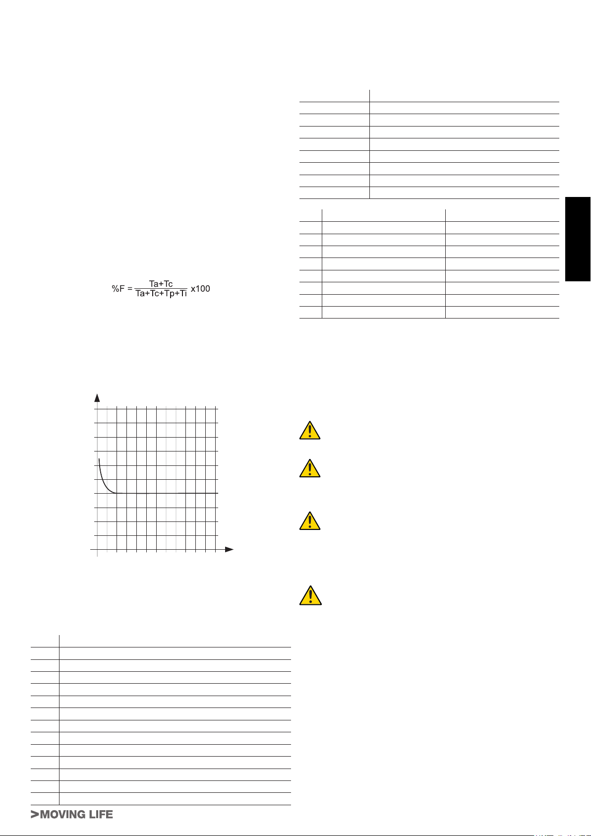
2.1_ Anwendungseinschränkungen und Abmessungen (Abb. 2)
Die Leistungsdaten von T-ONE3B, T-ONE5B, T-ONE5, T-ONE8 und
T-ONEXL sind im Kapitel „Technische Merkmale” angegeben; nur
sie ermöglichen eine korrekte Bewertung der Anwendungsignung.
Generell ist die Serie T-ONE in der Lage, Tore mit einem Gewicht
bis zu 300 kg (T-ONE3B), 500 kg (T-ONE5B und T-ONE5), 800 kg
(T-ONE8), und 1200 Kg (T-ONEXL) zu automatisieren.
Kurve max. Verwendung:
Die Kurve ermöglicht die Herausstellung der Höchstbetriebszeit
(T) aufgrund der Anwendungsfrequenz (F).
z.B.: Der Toröffner T-ONE5 kann ununterbrochen mit einer Anwendungsfrequenz von 40% in Betrieb sein.
Um eine gute Funktion zu gewährleisten, muss im Betriebsbereich
unter der Kurve vorgegangen werden.
Wichtig: Die Kurve wird bei einer Temperatur von 15°C erreicht.
Direkte Sonnenstrahlen können eine Verringerung der Anwendungsfrequenz bis zu 20% verursachen.
Kalkulierung der Anwendungsfrequenz:
Das ist der Prozentwert der effektiven Betriebszeit (Öffnen +
Schließen) gegenüber der Gesamtzykluszeit (Öffnen + Schließen
+ Stoppzeiten).
Die Kalkulationsformel lautet:
Wobei:
Ta = Die Öffnungszeit
Tc = Die Schließzeit
Tp = Die Pausenzeit
Ti = Der Abstand zwischen einem vollständigen Zyklus und dem
nächsten sind.
Percentuale
di lav. %
100
90
80
70
60
50
40
30
20
10
1 0
Tempo (h) Time (h) Zeit (Std.)
% Benutzungs-
% Duty cycle
frequenz
2 3 4 5 6 7 8 9 10 11 12
Temps (h)
% Fréquence
d’utilisation
% Frecuencia
% factor
de utilización
serviço
Tiempo (h) Tempo (h)
2.2_ Typische Anlage
In Abbildung 3 ist die typische Anlage einer Schiebetorautomatisierung mit T-ONE dargestellt.
Verkabelung:
In der typischen Anlage in Abbildung 3 sind auch die Kabel angegeben, die zur Verbindung der verschiedenen Vorrichtungen
erforderlich sind; in der Tabelle sind die Merkmale der Kabel verzeichnet.
Anschluss Kabeltyp
a: Stromleitung
b: Blinkleuchte
c: Antenne
d: Photozellen (TX)
e: Photozellen (RX)
f: Schlüsseltaster
g: Hauptschaltleiste
h: Bewegliche Schaltleisten
Bez. 230 V AC 12 V DC
a 3x1,5mm² 3x1,5mm²
b 2x0,5mm² 2x0,5mm²
c RG58 RG58
d 2x0,5mm² (TX) 2x0,5mm² (TX)
e 4x0,5mm² (RX) 4x0,5mm² (RX)
f* 3x0,5mm² 3x0,5mm²
g 2x0,5mm² 2x0,5mm²
h 2x0,5mm² 2x0,5mm²
* Wenn auch Art. P-300TSL installiert wird, für den Schlüsseltaster
ein Kabel 5x0,5 mm² vorsehen.
Anmerkungen:
• wenn das Versorgungskabel länger als 30m ist, muss ein Kabel mit größerem Querschnitt benutzt werden, z.B. 3x2,5mm²
und eine Sicherheitserdung in der Nähe der Automatisierung
vorgesehen werden.
Positionieren Sie das Steuergerät (falls extern) in der
unmittelbaren Nähe der Motoren.
Vermeiden Sie es, die Kabel der Zusatzvorrichtungen
in den Kabelkanälen zu verlegen, in denen andere Kabel vorhanden sind, die große Lasten oder Lampen mit
elektronischem Starter speisen.
Falls Tasten oder Kontrollleuchten in Wohnungen oder
Gebäuden installiert werden, die mehrere Meter vom
Steuergerät entfernt sind, empfehlen wir die Abkopplung des Signals über ein Relais, um Störungen zu vermeiden.
3_ INSTALLATION
Die Installation von T-ONE muss von qualiziertem
Personal unter genauester Beachtung der Gesetze,
Vorschriften und Verordnungen und der Angaben in
den vorliegenden Anweisungen ausgeführt werden.
DEUTSCH
NR. Beschreibung
1 Schlüsseltaster
2 Feste Hauptschaltleiste (Optional)
3 Photozellen
4 Bewegliche Hauptschaltleiste
5 Bügel des Endschalters “Geöffnet”
6 Zahnstange
7 Feste Nebenschaltleiste (Optional)
8 Blinkleuchte mit eingebauter Antenne
9 Toröffner
10 Bügel des Endschalters “Geschlossen”
11 Wireless-System
12 Bodendrehtor
13 Bewegliche Nebenschaltleiste (Optional)
3.1_ Vorprüfungen
Vor der Installation von T-ONE müssen folgende Kontrollen ausgeführt werden:
• Prüfen, ob das gesamte benutzte Material in bestem Zustand,
für den Einsatz geeignet und mit den Vorschriften konform ist.
• Prüfen, ob die Struktur des Tors so ausgelegt ist, dass es automatisiert werden kann.
• Prüfen, ob sich das Gewicht des Torügels innerhalb der Einsatzgrenzen in Kapitel “2.1 Einsatzgrenzen” bendet.
• Prüfen, ob entlang dem gesamten Lauf des Tors sowohl in
Schließung als auch in Öffnung keine größeren Reibungen anliegen.
• Prüfen, ob der Torügel nicht ausgleiten und nicht aus den Führungen treten kann.
• Die Robustheit der mechanischen Überlaufanschläge kontrollieren und prüfen, dass keine Verformungen erfolgen, auch
wenn der Torügel heftig auf diese aufprallen sollte.
T-ONE Series
17
Page 18
• Prüfen, dass der Torügel im Gleichgewicht ist: Er darf sich
nicht bewegen, wenn er in beliebiger Stellung stehen bleibt.
• Prüfen, ob sich der Bereich, in dem der Toröffner befestigt wird,
nicht überschwemmt werden kann; den Toröffner ggf. über
dem Boden installieren.
• Prüfen, ob die Entriegelung und eine leichte und sichere Bewegung von Hand des Torügels im Befestigungsbereich des
Toröffners möglich sind.
• Prüfen, ob sich die Befestigungsstellen der verschiedenen Vorrichtungen in stoßgeschützten Bereichen benden und ob die
Oberächen ausreichend solide sind.
• Elemente der Automatisierung sollten nicht in Wasser oder andere Flüssigkeit getaucht werden
• T-ONE nicht in der Nähe von Wärmequellen oder Flammen
oder in EX-gefährdeter, salz- oder säurehaltiger Umgebung
halten; dies kann Schäden und Betriebsstörungen in T-ONE
sowie Gefahren verursachen.
• Sollte der Torügel eine Eingangstür haben oder sich eine Tür
im Bewegungsbereich des Torügels bendet, ist sicher zu
stellen, dass diese den normalen Lauf des Tors nicht behindert;
ggf. für ein geeignetes Verblockungssystem sorgen.
• Die Steuerung an eine elektrische Versorgungsleitung mit Si-
DEUTSCH
cherheitserdung anschließen.
• Die elektrische Versorgungsleitung muss durch eine geeignete
magnetothermische Vorrichtung und Differentialschalter geschützt sein.
3.2_ Mechanische Installation
Herausstellung des Orts:
• Eine ähnliche Position wie im gestrichelten Bereich der Abb.
4 suchen, falls eine direkte Befestigung am Boden erfolgt (ein
oder mehrere Rohre zum Durchführen der Stromkabel vorsehen, 1 Abb. 4), wenn dieser aus Beton ist, oder wie in Abb. 5
gezeigt, wenn ausgehoben werden muss, Abb. 5A (Schließen
rechts) oder Abb. 5B (Schließen links).
Vorbereitung der Montageplatte:
• Die Fundamente mindestens 15 cm tief und ausreichend breit
ausgraben. Einen Kabelschutzmantel vorsehen.
Befestigung der Fundamentgegenplatte (mod. 400CPO):
• Nach Abschluss der Aushebung die Fundamentgegenplatte
vorbereiten, indem die Mauerwangen in der Platte auf dieselbe
Seite gebogen werden, wo die Einsätze (1 Abb. 6) zur Befestigung des Toröffners mittels Schrauben vorliegen. Mit Beton
ausgießen und die Mauerwangen bedecken, die Einsätze zur
Befestigung des Toröffners frei lassen; die Gegenplatte muss
1 oder 2 cm vom Boden abstehen und perfekt eben sein und
einen Abstand von ca. 42 mm vom Tor aufweisen (Abb. 6).
Befestigung der Fundamentgegenplatte (mod. 400CPOR):
• Die Fundamentplatte laut Abb. 7 zusammensetzen.
• Die Fundamentplatte muss wie in Abb. 7 A (Schließen rechts)
oder Abb. 7 B (Schließen links) platziert werden, um ein korrektes Eingreifen des Ritzels in die Zahnstange zu gewährleisten.
• Eine Bodenplatte laut Abb. 5 ausführen und die Fundamentplatte einschließlich einer oder mehrerer Stromkabelrohre
einmauern. Die perfekte Waagrechtigkeit der Platte mit einer
Wasserwaage prüfen. Abwarten, bis der Beton erhärtet ist.
• Die Stromkabel zum Anschluss an die Zubehörteile und die
Stromspeisung laut Abb. 3 vorbereiten.
Um die Anschlüsse leicht auszuführen, die Kabel ca. 30 cm aus
der Öffnung der Fundamentplatte austreten lassen.
Alternativ kann eine höhenverstellbare Gegenplatte (P-550CPMR
oder P-550CPMR1 - Abb. 17) benutzt werden. In diesem Fall müssen die festen Spreizbeine an das Gleis geschweißt werden und
witer befestigt mit 4 Fundament Dübeln M12 x 120 – siehe Abb.
18. Dann die verstellbare Gegenplatte wie auf Abb. 19 angegeben
befestigen.
Der Getriebemotor kann so einer bereits vorhandenen Anlage angepasst werden; die in Abb. 18 angegebenen Maße sind einzuhalten
18
Befestigung des Toröffners (auf Gegenplatte mod. 400CPO):
• Den Toröffner mit 4 Schrauben M8x30 und diesbezüglichen
Unterlegscheiben laut Abb. 8 befestigen.
• Alle Kabel durch die Öffnungen unter der Fundamentgegenplatte durchziehen.
• Wenn die Zahnstange schon vorliegt, 4 Gewindebolzen M8x30
(1 Abb. 8 - Optionals) und 4 Muttern M8 (2 Abb. 8 – Optionals)
einsetzen, um das Ritzel auf die richtige Höhe zu bringen, wobei 1-2 mm Spiel von der Zahnstange gelassen werden und die
perfekte Waagrechtigkeit des Toröffners mit einer Wasserwaage geprüft wird.
Befestigung des Toröffners (auf Gegenplatte mod. 400CPOR):
• Den Toröffner auf die Gegenplatte laut Abb. befestigen, wobei
4 Muttern M8 und 8 geeignete Unterlegscheiben verwendet
werden.
• Alle Kabel durch die Öffnungen unter der Fundamentgegenplatte durchziehen.
• Wenn die Zahnstange schon vorliegt, über die Muttern (1 Abb.
das Ritzel auf die richtige Höhe bringen, wobei 1-2 mm Spiel
von der Zahnstange gelassen werden und die perfekte Waagrechtigkeit des Toröffners mit einer Wasserwaage geprüft wird.
Befestigung der Zahnstange (mod. 400CN):
• Den Toröffner wie im Abschnitt „HANDENTRIEGELUNG“ angegeben entriegeln.
• Den Torügel ganz öffnen, das erste Teil der Zahnstange auf
das Ritzel legen und prüfen, dass der Anfang der Zahnstange
mit dem Anfang des Torügels gemäß Abbildung 10 übereinstimmt. Prüfen, ob zwischen Ritzel und Zahnstange ein Spiel
von 1-2 mm vorliegt.
• Legen Sie auf das Ritzel das erste Teil der Zahnstange auf
Höhe Torkante. Die Bohrungsstelle am Tor anzeichnen, mit einem Durchm. von 4 m durchbohren und die selbst einschneidende Schrauben Durchm. 6,3 mm einschrauben.
• Das Tor von Hand bewegen und prüfen, ob die Zahnstange auf
dem Ritzel liegt und die Vorgänge ab dem vorherigen Punkt
wiederholen.
• Ein anderes Zahnstangenteil an das vorherige legen und zur
Einstellung der Verzahnung der beiden Elemente die Schwalbenschwanzeingreifung laut Abb. 10 benützen.
• Das Tor von Hand bewegen und die Befestigungen wie beim
ersten Teil bis zur vollständigen Abdeckung des Tors fortführen,
Es ist wichtig, die Installationsmaße und die Distanz
zwischen dem Zahn des Zahnrads und dem Zahnstangenzahn laut Abb. 6 und 10 einzuhalten.
Anmerkung: Die Zahnstange muss auf dem Zahnrad
des Toröffners über die ganze Breite des Zahns verlaufen (Abb. 6).
Befestigung der Zahnstange (mod. 400CFZ12):
• Die drei Gewindesperrzähne in das Zahnstangenteil montieren
(A Abb. 11) und sie auf dem oberen Bereich des Langlochs
platzieren. Auf diese Weise ermöglicht das Spiel im Langloch
spätere eventuelle Einstellungen.
• Den Torügel von Hand in die geöffnete Position verschieben.
• Legen Sie auf das Ritzel das erste Teil der Zahnstange auf
Höhe Torkante. Und den Gewindesperrzahn auf das Tor wie in
Abb. 11 angegeben schweißen.
• Das Tor von Hand bewegen und prüfen, ob die Zahnstange auf
dem Ritzel liegt und den zweiten und dritten Sperrzahn schweißen.
• Ein anderes Zahnstangenteil an das vorherige legen und zur
Einstellung der Verzahnung der beiden Elemente die Schwalbenschwanzeingreifung laut Abb. 11 benützen.
• Das Tor von Hand bewegen und die drei Gewindesperrzähne
bis zur vollständigen Abdeckung des Tors schweißen.
Es ist wichtig, die Installationsmaße und die Distanz
zwischen dem Zahn des Zahnrads und dem Zahnstangenzahn laut Abb. 9 und 11 einzuhalten.
Anmerkung: Die Zahnstange muss auf dem Zahnrad
des Toröffners über die ganze Breite des Zahns verlaufen (Abb. 9).
T-ONE Series
Page 19

Befestigung und Einstellung Endschalter (T-ONE5 / T-ONE8 / T-ONEXL):
• Die Endschalterbügel “Öffnung” und “Schließung” mit den jeweiligen Stiftschrauben an den Außenseiten der Zahnstange,
wie in Abbildung 10 und 11 gezeigt, befestigen. Berücksichtigen, dass sich der Torügel bei Auslösung der Endschalter
noch ca. 2-3 cm weiter bewegt, daher die Endschalterbügel
etwas von den mechanischen Endanschlägen entfernt anbringen.
Es ist empfehlenswert, die Kontaktstelle des Endanschlags mit der Feder mit etwas Öl zu schmieren, um
das Gleiten zu erleichtern und das Einklemmen dieser
zu vermeiden.
Anmerkung: Für höchste Sicherheit müssen mechanische Anschläge (Bodendrehtore) mit Gummikappe,
wie in Abb. 3 eingebaut werden, wenn diese noch nicht
vorhanden sind.
Durch die Auswirkung oder die Summe verschiedener
Faktoren (thermische Dilatation, klimatische Bedingungen, Betriebsfrequenz usw.) kann es über den Tag
sowohl in der Phase der Öffnung, als auch in der Phase der Schließung zu einer Variation des Anhaltepunkts
des Tors kommen. Es ist daher nicht möglich zu garantieren, dass das Tor immer am gleichen Punkt anhält.
3.3_ Ausführung mit Kettenritzel: T-ONEC
Das Tor kann auch wie in Abb. 12 gezeigt angetrieben werden. Die
Kette wie in der Abbildung gezeigt durchziehen.
In der Abb. 12 wird außerdem die geforderte Kettenart aufgeführt
(Abstand 1/2“ x 5/16“).
3.4_
Einstellung der elektronischen (T-ONE3B, T-ONE5B),
elektrischen Kupplung (T-ONE5, T-ONE8, T-ONEXL)
ACHTUNG: Prüfen, ob der Wert der an den Stellen gemessenen Aufprallkraft laut Norm EN 12445 unter den
Angaben der Norm EN 12453 liegt.
• Alle Motoren der Serie T-ONE sind mit einstellbarem Encoder
zur Hinderniserfassung während des Laufs ausgestattet. Mit
dem hierfür vorgesehenen Potentiometer auf der Karte kann
das Höchstschubdrehmoment eingestellt werden.
5_ INSTALLATION DER 12V-BATTERIE (T-ONE5B)
Wenn der Toröffner mit einer Batterie ausgestattet werden soll, um
einen Betrieb auch ohne Strom zu garantieren, das Gehäuse entfernen und in den vorgesehenen Sitz (Abb. 13) einsetzen; Dann
die Speisungskabel an die Laschen schließen.
6_ HANDENTRIEGELUNG
Ohne Versorgungsspannung den Deckel des Schlosses anheben,
den hierfür vorgesehenen Schlüssel einstecken und wie in Abb. 14
gezeigt drehen.
Dann wie in Abb. 15 gezeigt, den Hebel nach außen ziehen, um
die Betätigung des Tors von Hand zu ermöglichen.
7_ ENDSCHALTER (T-ONE5 / T-ONE8 / T-ONEXL)
Die Serie T-ONE (230 Vac) wurde entwickelt, um mit dem elektromechanischen Endanschlag mit Mikroswitch zu funktionieren.
Die Kabel sind wie in Abb. 16 angeschlossen:
1= grau (gemeinsam);
2 = orange (Endschalter schließt – N.C.-Kontakt);
3 = rot (Endschalter öffnet – N.C.-Kontakt);
4= grau (gemeinsam);
Wenn - wie in Abb. 16 dargestellt - das Zahnrad im Uhrzeigersinn
dreht und die Feder wie angegeben versetzt wird, hält der Lauf
nicht an – die Position des roten und orangefarbenen Kabels im
Klemmenbrett der Steuerkarte umkehren.
8_ ENDPRÜFUNGEN UND START
Der Anschluss der Versorgung von T-ONE muss von erfahrenem Fachpersonal mit den erforderlichen Kenntnissen und unter voller Einhaltung von Gesetzen, Vorschriften und Verordnungen ausgeführt werden.
Sobald T-ONE mit Spannung versorgt ist, sollten einige einfache
Überprüfungen ausgeführt werden:
1. Prüfen, ob die Leds in der Steuerkarte erleuchtet sind.
2. Prüfen, ob der Motor keine Torbewegung verursacht und ob
das Blinklicht abgeschaltet ist.
Sollte all dies nicht der Fall sein, muss die Versorgung
zur Steuerung unverzüglich ausgeschaltet werden,
dann die elektrischen Anschlüsse genauer kontrollieren.
DEUTSCH
3.5_ Installation der verschiedenen Vorrichtungen
Die Installation der anderen vorgesehenen Vorrichtungen nach
den jeweiligen Anweisungen ausführen. In der Abbildung 3 die Vorrichtungen prüfen, die an T-ONE angeschlossen werden können.
4_ ELEKTRISCHE ANSCHLÜSSE
Vor allen Eingriffen sicherstellen, dass der Toröffner
nicht stromgespeist ist.
• Um die Anschlüsse auszuführen, das Gehäuse vom Toröffner nehmen, die Speisungskabel durch die Öffnungen an der
Fundamentgegenplatte (wenn vorhanden) und durch den unteren Körper des Toröffners ziehen, dann für den Anschluss
am Klemmenbrett der Steuerkarte in der Halterung der elektrischen Bestandteile vorbereiten.
•
Ein Kabel mit einem Mindestschnitt von 2,5 mm² für die Leistungskreise (T-ONE3B und T-ONE5B) und 1,5 mm² (T-ONE5, TONE8 und T-ONEXL), 0,5 mm² für die Leistungskreise vorsehen.
Für die Anschlüsse an die Steuerkarten siehe diesbezügliche Gebrauchsanweisung:
- K120M für T-ONE3B;
- K125M für T-ONE5B;
- K580M für T-ONE5, T-ONE8 und T-ONEXL.
T-ONE Series
Weitere nützliche Auskünfte über die Fehlersuche und die Diagnose benden sich in Kapitel “7.6 Probleme und deren Lösung”.
Bezüglich anderer einzustellender Parameter, Erlernung des
Laufs, Einstellung der Kupplung, Verlangsamung, Einstellung der
automatischen Schließzeit, Empndlichkeit der Hinderniserfassung usw., beziehen Sie sich bitte auf die Anleitungen der elektronischen Steuerkarten.
9_ ABNAHME UND INBETRIEBNAHME
Um höchste Sicherheit zu gewährleisten, sind dies die wichtigsten
Schritte zur Ausführung der Automatisierung. Die Abnahme kann
auch als regelmäßige Überprüfung der Bestandteile der Automatisierung genützt werden.
Die Abnahme der gesamten Anlage muss von erfahrenem Fachpersonal ausgeführt werden, das die erforderlichen Tests je nach vorhandenem Risiko auszuführen
und die Einhaltung der von Gesetzen, Vorschriften und
Verordnungen vorgesehenen Punkte zu überprüfen
hat, und insbesondere alle Anforderungen der Norm
EN12445 sowie die Testmethoden zur Überprüfung von
Torautomatisierungen festlegt.
9.1_ Abnahme
Für jedes einzelne Element der Automatisierung wie zum Beispiel
Schaltleisten, Photozellen, Notstopps usw. ist eine spezielle Abnahmephase erforderlich; für diese Vorrichtungen sind die Verfahren in den jeweiligen Anleitungen auszuführen.
19
Page 20

Für die Abnahme von T-ONE ist die folgende Sequenz auszuführen:
1. Prüfen, ob alles in der vorliegenden Anweisung und insbesondere das in Kapitel 1 “HINWEISE” angegebene genauestens
eingehalten ist.
2. Die vorgesehenen Steuervorrichtungen (Schlüsseltaster, Steuertasten oder Funksender) verwenden, die Schließung und
Öffnung des Tors testen und prüfen, ob das Verhalten wie vorgesehen ist.
3. Den korrekten Betrieb aller Sicherheitsvorrichtungen der Anlage einzeln überprüfen (Photozellen, Schaltleisten, Notstopps
usw.).
4. Zur Überprüfung der Photozellen und insbesondere um zu prüfen, dass keine Interferenzen mit anderen Vorrichtungen vorhanden sind, einen Zylinder mit 5 cm Durchmesser und 30 cm
Länge auf der optischen Achse zuerst nah an TX, dann nah an
RX und abschließend in ihrer Mitte durchführen und prüfen,
dass die Vorrichtung in allen Fällen ausgelöst wird und vom aktiven Zustand auf den Alarmzustand übergeht und umgekehrt.
Dann prüfen, dass in der Steuerung der vorgesehene Vorgang
erfolgt, während der Schließung also zum Beispiel eine Umkehrung der Bewegung.
5. Falls die durch die Torbewegung verursachten Gefahren mittels
DEUTSCH
Begrenzung der Aufprallkraft abgesichert worden sind, muss
die Kraft nach den Verordnungen der Vorschrift EN 12445 gemessen werden. Falls die “Geschwindigkeitsregelung“ und die
Kontrolle der “Motorkraft” als Hilfsmittel für das System zur Aufprallkraftreduzierung benutzt werden, die Einstellungen erproben und diejenigen nden, mit denen die besten Ergebnisse
erzielt werden.
9.2_ Inbetriebsetzung
Die Inbetriebsetzung darf erst erfolgen, nachdem alle
Abnahmephasen von T-ONE sowie der anderen Vorrichtungen erfolgreich beendet sind. Eine teilweise
oder vorübergehende Inbetriebsetzung ist unzulässig.
• Die technischen Unterlagen der Automatisierung zusammenstellen und diese mindestens 10 Jahre lang aufbewahren. Sie
müssen mindestens folgendes umfassen: Gesamtzeichnung
der Automatisierung, Schaltplan mit den elektrischen Anschlüssen, Risikoanalyse und jeweilige angewendete Lösungen, Konformitätserklärung des Herstellers für alle benutzten
Vorrichtungen (für T-ONE die anliegende “CE-Konformitätserklärung” verwenden); Kopie der Bedienungsanweisungen und
des Wartungsplans der Automatisierung.
• Bringen Sie am Tor ein Schild mit mindestens folgenden Daten
an: Automationstyp, Name und Adresse des Herstellers (Verantwortlicher der “Inbetriebsetzung”), Seriennummer, Baujahr
und CE-Markierung.
• In Tornähe auf bleibende Art ein Etikett oder ein Schild befestigen, dass die Angaben zur Durchführung der Entriegelung und
der Bewegung von Hand enthält.
• Die Konformitätserklärung der Automatisierung anfertigen und
dem Inhaber aushändigen.
• Das Handbuch “Anweisungen und Hinweise für die Bedienung
der Automatisierung“ anfertigen und dem Inhaber der Automatisierung übergeben.
• Den Wartungsplan anfertigen und dem Inhaber der Automatisierung aushändigen. Er enthält die Wartungsvorschriften der
einzelnen Vorrichtungen.
• Vor der Inbetriebsetzung der Automatisierung, den Inhaber
auf geeignete Weise und schriftlich (z.B. in den “Anweisungen
und Hinweise für die Bedienung der Automatisierung“ über die
noch vorhandenen Gefahren und Risiken informieren.
10_ ANWENDUNG
Die Toröffner der Serie T-ONE wurde entwickelt, um Tore mit
waagrechtem Verlauf mit einem Torügel mit max. Gewicht von
300 kg (T-ONE3B), 500 kg (T-ONE5B und T-ONE5), 800 kg (T-
ONE8) und 1200 Kg (T-ONEXL) zu bewegen:
Die Verwendung der Einrichtung für andere Zwecke
oder unter anderen Umständen als genannt ist ausdrücklich verboten.
20
Das installierte elektronische Steuergerät ermöglicht die Auswahl
der Betriebsart:
Automatisch: Ein Steuerimpuls führt das Öffnen und Schließen
des Tors aus;
Halbautomatisch: Ein Steuerimpuls führt das Öffnen oder Schließen des Tors aus;
Bei Stromausfall kann das Tor dank der Handbetätigung trotzdem
bedient werden; hierfür wird die Handentriegelung benützt. Die
Schiebetorantriebe T-ONE3B und T-ONE5B können mit Pufferbatterie funktionieren. Die Batterien garantieren einen normalen
Betrieb der Automatisierung auch bei Netzstromausfall.
Wir erinnern daran, dass es sich um eine automatische und stromgespeiste Vorrichtung handelt; somit müssen die notwendigen
Vorsichtsmaßnahmen beachtet werden. Insbesondere empfehlen
wir:
• Das Gerät nicht mit nassen Händen oder Füßen oder barfuss
zu berühren;
• Den Strom trennen, bevor das Steuergehäuse und/oder der
Toröffner geöffnet werden;
• Den Motor nicht berühren, bevor Sie nicht sicher sind, dass er
abgekühlt ist;
• Das Tor nur in Bewegung setzen, wenn es gut sichtbar ist;
• Sich außerhalb des Wirkungskreises des Tors aufhalten, wenn
dieses in Bewegung ist: Abwarten, bis es steht;
• Nicht zulassen, dass Kinder oder Tiere in der Nähe des Tors
spielen;
• Nicht zulassen, dass Kinder oder unfähige Personen die Fernsteuerung oder andere Betätigungsvorrichtungen benützen;
• Eine regelmäßige Instandhaltung ausführen.
• Im Falle einer Störung, die Stromspeisung trennen und das Tor
von Hand bedienen, wenn dies möglich und sicher ist. Jegliche
Eingriffe vermeiden und einen zugelassenen Techniker rufen.
ES IST AUSDRÜCKLICH UNTERSAGT, DIE AUTOMATISIERUNG MIT HYDROREINIGERN ODER ÄHNLICHEN
GERÄTEN ZU WASCHEN. ES IST STRENG VERBOTEN,
WASSER DIREKT AUF DIE AUTOMATISIERUNG ZU
SPRITZEN.
11_ WARTUNG
Die Toröffner der Serie T-ONE benötigen wenig Instandhaltung. Ihr
guter Betrieb hängt jedoch auch vom Zustand des Tors ab: Somit
beschreiben wir kurz die auszuführenden Arbeiten, um ein immer
efzientes Tor zu haben.
Achtung: Außer dem Wartungstechniker, der spezialisiert sein muss, darf niemand das automatische Tor
während der Wartung steuern.
Wir empfehlen somit, die Stromspeisung zu trennen und so auch
die Gefahr eines Stromschlags zu vermeiden. Wenn die Speisung
dagegen für einige Prüfungen vorhanden sein muss, empfehlen
wir, jede Steuervorrichtung (Fernsteuerungen, Druckknopftafeln
usw.), außer der vom Wartungstechniker verwendeten Vorrichtung, zu kontrollieren oder zu deaktivieren.
Gewöhnliche Wartung
Jeder der folgenden Vorgänge muss ausgeführt werden, wenn er
für notwendig betrachtet wird und auf jeden Fall alle 6 Monate bei
einem Hausgebrauch (zirka 3000 Betriebszyklen) und alle 2 Monate bei einer intensiven Nutzung, z.B. Wohnanlagen (ebenso alle
3000 Betriebszyklen).
Tor
- Die Gleitrollen des Tors mit einer Ölkanne schmieren;
- Die Sauberkeit und Dichtheit der Zahnstange prüfen;
Automatisierungsanlage
- Die Funktion der Sicherheitsvorrichtungen prüfen (Photozellen, Pneumatikleiste, Drehmomentbegrenzer, usw.);
Außergewöhnliche Wartung
Wenn bedeutende Eingriffe an mechanischen Teilen notwendig
werden, empfehlen wir die Entfernung des Toröffners, um eine
Reparatur in der Werkstatt durch Techniker des Herstellers oder
durch zugelassene Techniker zu ermöglichen.
T-ONE Series
Page 21

12_ SONDERZUBEHÖR
Das Angebot der Motoren der Serie T-ONE wird durch die folgenden Zubehörteile (Optionals) vervollständigt:
• P-650ESE03 Handentriegelung, extern, mit Verkleidung;
• P-400FCM Magnetendschalter.
13_ GERÄUSCH
Das durch den Toröffner gebildete Geräusch ist unter normalen
Betriebsbedingungen konstant und überschreitet 70 dB nicht.
14_ ABBRUCH
Die Beseitigung der Materialien muss bei Einhaltung der geltenden
Vorschriften ausgeführt werden.
Im Falle eines Abbruchs der Automatisierung bestehen keine besonderen Gefahren oder Risiken, die durch die Automatisierung
verursacht werden.
Im Falle eines Recyclings der Materialien ist es empfehlenswert,
sie nach Art zu trennen (Elektroteile – Kupfer - Alu – Kunststoff –
usw.).
15_ DEMONTAGE
Falls die Automatisierung zerlegt wird, um dann wieder an einem
anderen Ort montiert zu werden, muss folgendes ausgeführt werden:
- Die Stromspeisung trennen und die ganze Elektrik abtrennen;
- Den Toröffner von der Befestigungsplatte entfernen;
- Alle Anlagenteile ausbauen;
- Falls einige Teile nicht entfernt werden können oder beschädigt
sind, müssen sie ersetzt werden.
DEUTSCH
16_ MANGELHAFTE FUNKTION: URSACHEN UND
LÖSUNGEN
Das Tor öffnet sich nicht, der Motor dreht nicht.
- Prüfen, ob Photozellen oder Schaltleisten verschmutzt, behindert oder nicht angepasst sind. Je nach Fall vorgehen.
- Prüfen, ob die elektronische Einrichtung regulär gespeist wird,
die Unversehrtheit der Sicherungen prüfen.
- Durch die Diagnose-Leds des Steuergeräts (siehe jeweilige
Anleitungen) kontrollieren, ob die Funktionen korrekt sind.
Eventuell die Ursache des Defekts herausstellen. Wenn die
Leds anzeigen, dass eine Startsteuerung vorliegt, kontrollieren, ob Funksteuerungen, Startdruckknöpfe oder andere Vorrichtungen vorliegen, die den Startkontakt aktiviert halten (geschlossen).
- Wenn das Steuergerät nicht funktioniert, austauschen.
Falls die oben genannten Umstände ein negatives Ergebnis ergeben, den Toröffner austauschen.
Das Tor öffnet sich nicht, der Motor dreht, aber es erfolgt keine Bewegung.
- Die Handentriegelung blieb aktiviert. Den automatischen Betrieb wieder aktivieren.
- Kontrollieren, ob das Tor an den mechanischen Endanschlägen anliegt. Das Tor von Hand entriegeln, bewegen und den
automatischen Betrieb wieder aktivieren. Die Position der Endanschlagsgleitbacken kontrollieren und korrigieren.
- Kontrollieren, dass keine mechanischen Torpositionierungsdefekte vorliegen.
Falls die oben genannten Umstände ein negatives Ergebnis ergeben, den Toröffner austauschen.
T-ONE Series
21
Page 22

INTEGRIERUNGSERKLÄRUNG DES HERSTELLERS
(gemäß der Europäischen Richtlinie 2006/42/EG Anl. II.B)
Hersteller: TAU S.r.l.
Adresse: Via E. Fermi, 43
36066 Sandrigo (Vi)
ITA LY
Erklärt unter seiner Haftung, dass das Produkt: Elektromechanischer Antrieb
für die automatische Bewegung von: Schiebetore
für eine Anwendung: Privat / Gewerbe
DEUTSCH
Einschließlich: Elektronische Steuerung und Empfänger
Modell: T-ONE
Typ: T-ONE3B / T-ONE5B / T-ONE5 / T-ONE8 / T-ONEXL
Seriennummer: SIEHE SILBERETIKETTE
Handelsbezeichnung: SCHIEBETORANTRIEB FÜR PRIVAT UND GEWERBE
ausgeführt wurde, um in einen Verschluss integriert zu werden (Schiebetore) oder um mit anderen Vorrichtungen kombiniert zu werden,
um diesen Verschluss zu bewegen, und somit gemäß der Maschinenrichtlinie 2006/42/EG eine Maschine darstellt.
Außerdem erklärt er, dass dieses Produkt den grundsätzlichen Sicherheitseigenschaften der folgenden Richtlinien EWG entspricht:
- 2006/95/EG Niederspannungsrichtlinie
- 2004/108/EG Richtlinie für elektromagnetische Kompatibilität
Und wo gefordert, der Richtlinie:
- 1999/5/CE Radio equipment and telecommunications terminal equipment
Außerdem wird erklärt, dass es nicht zugelassen ist, die Vorrichtung in Betrieb zu setzen, bis die Maschine, in die sie integriert wird
oder deren Bestandteil sie sein wird, identiziert und die Konformität gegenüber dem Inhalt der Richtlinie 2006/42/EG erklärt wurde.
Er verpichtet sich, auf ausdrücklichen Wunsch der nationalen Behörden, Informationen über die Fastmaschinen zu übersenden.
Sandrigo, 14/11/2011
Der gesetzliche Vertreter
_________________________________________
Bruno Danieli
Name und Adresse der beauftragten Person zur Vorlegung der zugehörigen technischen Unterlagen:
Loris Virgilio Danieli - via E. Fermi, 43 - 36066 Sandrigo (Vi) Italy
22
T-ONE Series
Page 23

> ITALIANO
Guida
Utente
SBLOCCO MANUALE
Nel caso si renda necessario movimentare manualmente il cancello,
per mancanza di alimentazione elettrica o disservizio dell’automazione,
è necessario agire sul dispositivo di sblocco come segue:
1_ Levare il coperchietto della serratura, inserire l’appostita chiave e
ruotare come indicato in g. 1.
2_ Tirare la leva di sblocco come indicato in g. 2.
3_ Effettuare manualmente la manovra di apertura o chiusura.
RIPRISTINO DEL FUNZIONAMENTO NORMALE
Per evitare che un impulso involontario possa azionare il cancello durante
la manovra, prima di ribloccare l’operatore, togliere alimentazione
all’impianto.
1_ Richiudere la leva di sblocco.
2_ Ruotare la chiave in senso antiorario.
3_ Estrarre la chiave e chiudere il coperchietto della serratura.
4_ Muovere il cancello no all’ingranamento dello sblocco.
ISTRUZIONI ED AVVERTENZE DESTINATE ALL’UTILIZZATORE DELL’AUTOMAZIONE
COMPLIMENTI per aver scelto per la vostra automazione un prodotto Tau!
Tau S.r.l. produce componenti per l’automazione di cancelli, porte, barriere, serramenti: motoriduttori, centrali di comando, radiocomandi,
lampeggianti, fotocellule e accessori.
I prodotti Tau sono realizzati solo con materiali e lavorazioni di qualità e, come azienda, siamo alla costante ricerca di soluzioni innovative
che semplichino sempre più l’utilizzo delle nostre apparecchiature, curate sotto ogni aspetto (tecnico, estetico ed ergonomico): nella grande
gamma Tau il vostro installatore può scegliere il prodotto che meglio soddisfa le vostre esigenze.
Tau però non produce la vostra automazione che, invece, è il risultato di un’opera di analisi, di valutazione, di scelta dei materiali e realizzazione
dell’impianto eseguita dal vostro installatore di ducia.
Ogni automazione, pertanto, è unica e solo il vostro installatore può eseguire un impianto secondo le vostre esigenze (in quanto dotato
dell’esperienza e della professionalità necessarie), sicuro ed afdabile nel tempo; e soprattutto a regola d’arte, rispondente cioè alle normative
in vigore.
Un impianto di automazione è una bella comodità, oltre che un valido sistema di sicurezza e, con poche, semplici attenzioni, è destinato a
durare negli anni.
DESCRIZIONE
L’automazione T-ONE per cancelli scorrevoli è un operatore elettromeccanico irreversibile che trasmette il movimento all’anta tramite un
sistema a vite senza ne. L’operatore è disponibile nelle versioni 12 V e 230 V. Il sistema irreversibile garantisce il blocco meccanico dell’anta
quando il motore non è in funzione. Un comodo e sicuro sistema di sblocco con chiave personalizzata permette la movimentazione manuale
dell’anta in caso di disservizio o di mancanza di alimentazione.
Anche se l’automazione in vostro possesso soddisfa il livello di sicurezza richiesto dalle normative, questo non esclude l’esistenza di un “rischio
residuo”, cioè la possibilità che si possano generare situazioni di pericolo, dovute ad un utilizzo incosciente e/o errato. Per questo motivo
riportiamo alcuni consigli sui comportamenti da tenere per evitare ogni inconveniente:
- Al primo utilizzo: chiedete al vostro installatore di spiegarvi l’origine dei rischi residui e leggete il presente manuale di istruzioni ed
avvertenze per l’utilizzatore consegnatovi dall’installatore. Conservate il manuale per qualsiasi problema futuro e ricordatevi di consegnarlo
ad un eventuale nuovo proprietario dell’impianto.
- L’impianto di automazione esegue fedelmente i vostri comandi: un uso incosciente e/o improprio può divenire pericoloso. Evitate
quindi di azionare l’automazione quando nel suo raggio d’azione si trovino persone, animali e/o cose.
- NON È UN GIOCO! Fate in modo che i bambini non giochino in prossimità dell’impianto e tenete i telecomandi fuori della loro portata.
- Anomalie: ad ogni comportamento anomalo dell’impianto, togliete l’alimentazione elettrica all’automazione ed eseguite lo sblocco
manuale (come da gura). Evitate qualsiasi intervento personale e chiamate il vostro installatore: una volta sbloccato, l’impianto funzionerà
manualmente come prima dell’installazione.
- Manutenzione: per durare nel tempo e funzionare in completa sicurezza, come qualsiasi altro macchinario, l’impianto necessita di una
periodica manutenzione. Stabilite insieme al vostro installatore i tempi di tale manutenzione. Tau consiglia un intervento ogni 6 mesi per un
normale uso domestico, che può variare in funzione dell’intensità d’uso (sempre ogni 3000 cicli di lavoro).
N.B. Qualsiasi tipo di intervento (controllo, manutenzione e/o riparazione) deve essere eseguito solo da personale qualicato.
- Non modicare l’impianto, nè i relativi parametri di programmazione e di regolazione: la responsabilità è dell’installatore.
N.B. Il collaudo nale, le manutenzioni periodiche e le eventuali riparazioni devono essere documentate (negli appositi spazi) da
chi le esegue e i documenti conservati dal proprietario dell’impianto (IN CASO DI MANCATA DOCUMENTAZIONE LA GARANZIA
DECADE).
- Smaltimento: al termine della vita dell’impianto assicuratevi che lo smantellamento venga eseguito da personale qualicato e che i
materiali vengano riciclati o smaltiti secondo le norme valide a livello locale.
La manovra manuale deve essere eseguita SOLO a porta ferma e DOPO aver tolto l’alimentazione alla centrale elettrica.
1 2
Nota: se il vostro impianto è dotato di un telecomando che dopo qualche tempo vi sembra funzionare peggio, oppure non funzionare affato,
potrebbe semplicemente dipendere dall’esaurimento della pila (a seconda del tipo, possono trascorrere diversi mesi no a 2/3 anni). Ve ne
potete accorgere dal fatto che la spia di conferma della trasmissione è debole, oppure si accende solo per un breve istante. Prima di rivolgervi
all’installatore provate a scambiare la pila con quella di un altro trasmettitore eventualmente funzionante: se questa fosse la causa dell’anomalia,
sarà sufciente sostituire la pila con un’altra dello stesso tipo.
Nel caso voleste aggiungere nella vostra casa un nuovo tipo di automazione, rivolgendovi allo stesso installatore e alla Tau vi garantirete,
oltre che la consulenza di uno specialista e i prodotti più evoluti del mercato, il migliore funzionamento e la massima compatibilità delle
automazioni.
Vi ringraziamo per aver letto queste raccomandazioni, e vi auguriamo la massima soddisfazione dal vostro nuovo impianto: per ogni tipo di
esigenza rivolgetevi con ducia al vostro installatore.
Guida Utente - User Guide - Führer Benutzer - Guide Usager - Guía Usuario - Guia do Utilizador
1
- - -- - - - - - - - - - - - - - - - - - - - - - - - - - - - - - - - - - - - - - - - - - - - - - - - - - - - - - - - - - - - - - - - - - - - - - - - - - - - - - - - - - - - - - - - - - - - - -
Page 24

> ENGLISH
User
Guide
MANUAL OPERATION
If the gate has to be operated manually due to a power cut or malfunction
of the automated system, use the release device as follows:
1_ Remove the cover of the lock, t the relative key and turn it as shown
in g. 1.
2_ Pull the release lever as shown in g. 2.
3_ Open and close the gate manually.
RESTORING NORMAL OPERATION
To prevent an involuntary pulse from activating the gate during the
manoeuvre, cut power to the system before relocking the operator.
1_ Re-close the release lever.
2_ Turn the key anti-clockwise.
3_ Remove the key and close the cover of the lock.
4_ Move the gate until the release meshes.
INSTRUCTIONS AND WARNINGS FOR AUTOMATIC SYSTEM USERS
CONGRATULATIONS on choosing a Tau product for your automation system!
Tau S.r.l. produces components for automatic gates, doors, barriers and shutters. These include gear motors, control units, radio control
devices, ashing lights, photocells and accessories.
Tau products are exclusively made with top quality materials and processes and, as a company, we constantly research and develop innovative
solutions in order to make our equipment increasingly easier to use. We also pay great attention to all details (technology, appearance and
ergonomics). The extensive Tau range makes it possible for your tter to choose the product which best meets your requirements.
Tau, however, does not produce your automated system as this is the outcome of a process of analysis, evaluation, choice of materials and
installation performed by your tter.
Each automated system is unique, therefore, and only your tter has the experience and professionalism required to create a system that is
tailor-made to your requirements, featuring long-term safety and reliability, and, above all, professionally installed and compliant with current
regulations.
An automated system is handy to have as well as being a valid security system. Just a few, simple operations are required to ensure it lasts for
years.
1 2
DESCRIPTION
The T-ONE automated system for sliding gates is an electro-mechanical non-reversing operator that transmits motion to the leaf via a worm
screw system.
The operator is available in 12 Vdc and 230 Vac versions.
The non-reversing system ensures the leaf is mechanically locked when the motor is not operating. A convenient and safe release system with
customised key makes it possible to manually move the leaf in the event of a malfunction or of a power failure.
Even if your automated system satises regulatory safety standards, this does not eliminate “residue risks”, that is, the possibility of dangerous
situations being generated, usually due to irresponsible and/or incorrect use. For this reason we would like to give you some suggestions on
how to avoid these risks:
- Before using the system for the rst time: ask your tter to explain how residue risks can arise and read the instructions and warnings in
the user handbook that your tter will have given you. Keep this manual for future use and, if you should ever sell your automated system,
hand it over to the new owner.
- Your automated system carries out your commands to the letter: irresponsible and/or incorrect use may cause it to become dangerous.
Do not use the system if people, animals and/or objects enter its operating area.
- IT IS NOT A TOY! Make sure children do not play near the system and keep the remote control device out of their reach.
- Faults: If you notice any abnormal behaviour, disconnect the system from the power supply immediately and perform the manual release
operation (see gure). Do not attempt to repair the door but call in your tter: the system will operate manually as it did before installation.
- Maintenance: to ensure long life and totally safe operation, the system required routine maintenance, just like any other piece of machinery.
Establish maintenance times together with your tter. Tau recommends a frequency of 6 months for normal domestic installations but this
may vary depending on the intensity of use (always every 3000 work cycles).
N.B.: All controls, maintenance work and/or repairs may only be carried out by qualied personnel.
- Do not modify the plant or the relative programming and adjustment parameters: your tter will see to that.
N.B. Final testing, routine maintenance and any repairs must be documented by the tter (in the relative spaces) and such documents
kept by the owner of the system (IF THE DOCUMENTS ARE NOT PRODUCED, THE WARRANTY WILL EXPIRE).
- Disposal: At the end of system life, make sure that it is demolished by qualied personnel and that the materials are recycled or disposed
of according to local regulations.
The manual manoeuvre must ONLY be done with the door stopped and AFTER disconnecting power from the electrical control unit.
N.B.: if your remote control unit (if supplied) starts working badly after a time, or does not work at all, the batteries may be at (they can last
from several months to 2/3 years depending on what type is used). This can be seen from the fact that the transmission conrmation LED gets
dimmer or only turns on for brief moments. Before contacting your tter, try exchanging the battery with one from a good transmitter: if this is the
reason for the fault, simply replace the battery with another one of the same type.
If you wish to add a new automated system to your house, contact your tter and we at Tau to have the advice of a specialist, the most developed
products on the market, best operation and maximum automation compatibility.
Thank you for reading these suggestions and we trust you are fully satised with your new system: please contact your tter for any further
requirements.
2
Guida Utente - User Guide - Führer Benutzer - Guide Usager - Guía Usuario - Guia do Utilizador
Page 25

> DEUTSCH
Führer
Benutzer
MANUELLER BETRIEB
Sollte eine manuelle Bewegung des Tors aufgrund eines Ausfalls der
Stromversorgung oder einer Betriebsstörung der Automation erforderlich
werden, so ist die Entriegelungsvorrichtung wie folgt zu bedienen:
1_ Deckel des Schlosses heben, den Schlüssel einstecken und wie in
Abb. 1 gezeigt drehen.
2_ Den Entriegelungshebel ziehen, wie in Abb. 2 gezeigt.
3_ Manuell die Bewegungen der Öffnung oder der Schließung
ausführen.
WIEDERHERSTELLUNG DES NORMALEN BETRIEBS
Um zu vermeiden, daß das Tor während des Manövers versehentlich
betrieben wird, ist vor der erneuten Verriegelung des Antriebs die
Stromversorgung zur Anlage zu unterbrechen.
1_ Den Entriegelungshebel erneut schliessen.
2_ Den Schlüssel in Gegenuhrzeigersinn drehen.
3_ Den Schlüssel abnehmen und den Deckel des Schlosses schließen.
4_ Das Tor bewegen, bis die Entriegelung einrastet.
ANWEISUNGEN UND HINWEISE FÜR DEN BENUTZER DER AUTOMATISIERUNG
WIR GRATULIEREN IHNEN zur Wahl eines Tau Produktes für Ihre Automatisierung!
Tau S.r.l. stellt Komponenten für die Automatisierung von Toren, Türen, Schranken und Fenstern her: Getriebemotoren, Steuerzentralen,
Funksteuerungen, Blinkleuchten, Fotozellen und Zubehör.
Die Tau Produkte werden nur mit Materialien und Bearbeitungen hoher Qualität hergestellt, und unsere Firma ist auf der ständigen Suche nach
innovativen Lösungen, mit denen die Benutzung unserer Apparaturen, die in jeder Hinsicht (Technik, Aussehen und Ergonomie) besonders
gepegt sind, immer einfacher wird: unter dem großen Tau Sortiment kann Ihr Installateur das Produkt auswählen, das Ihrem Bedarf am besten
entspricht.
Tau ist aber nicht der Hersteller Ihrer Automatisierung, die dagegen das Ergebnis des Werks Ihres Vertrauensinstallateurs ist, der sich mit den
notwendigen Untersuchungen und Bewertungen, der Wahl der Materialien und der Verwirklichung die Anlage beschäftigen wird.
Jede Automatisierung ist daher einzigartig und nur Ihr Installateur kann eine Anlage ausführen, die Ihrem Bedarf entspricht (er besitzt die
notwendige Erfahrung und Professionalität), die sicher und auf Zeit zuverlässig und vor allem fachgerecht ist und mit den gültigen Vorschriften
übereinstimmt.
Eine Automatisierungsanlage ist etwas wirklich bequemes, aber auch ein gutes Sicherheitssystem, und mit ein paar einfachen Maßnahmen
wird sie jahrelang dauern.
BESCHREIBUNG
Die Automation T-ONE für Schiebetore ist ein irreversibler elektromechanischer Antrieb, der über ein Schneckensystem die Bewegung auf den
Flügel überträgt.
Der antrieb ist Verfügbar in 12 Vdc und 230 Vac.
Das irreversible System gewährleistet die mechanische Verriegelung des Flügels, wenn der Motor nicht in Betrieb ist. Ein praktisches und sicheres
Freigabesystem mit individuellem Schlüssel ermöglicht die manuelle Bewegung des Flügels bei Betriebsstörungen oder Stromausfall.
Auch wenn Ihre Automatisierung dem Sicherheitsniveau entspricht, das von den Vorschriften gefordert wird, schließt dies das Vorhandensein
eines „Restrisikos” nicht aus, bzw. der Möglichkeit, dass Gefahren aufgrund eines fahrlässigen und/oder falschen Gebrauchs erzeugt werden
können. Aus diesem Grund geben wir hier einige Verhaltensweisen an, um diese möglichen Restrisiken zu vermeiden:
- Bei der ersten Benutzung: bitten Sie Ihren Installateur, Ihnen den Ursprung der Restrisiken zu erklären, und lesen Sie die vorliegenden
Anweisungen und Hinweise für den Benutzer, die Ihnen vom Installateur übergeben werden. Bewahren Sie die Anleitung für zukünftige
Probleme auf, und übergeben Sie diese ggf. dem neuen Besitzer der Anlage.
- Die Automatisierungsanlage folgt getreu Ihren Befehlen: ein fahrlässiger und/oder unsachgemäßer Gebrauch kann gefährlich sein.
Betätigen Sie daher die Automatisierung nicht, wenn sich Personen, Tiere und/oder Gegenstände in ihrem Aktionskreis benden.
- SIE IST KEIN SPIEL! Lassen Sie Kinder nicht in der Nähe der Anlage spielen und halten Sie die Fernbedienungen außer deren
Reichweite.
- Störungen: schalten Sie bei jedem ungewöhnlichen Verhalten der Anlage die Stromversorgung zur Automatisierung ab und entriegeln
Sie von Hand (siehe Abbildung). Vermeiden Sie jeden persönlichen Eingriff und rufen Sie Ihren Installateur: nach dem Entriegeln wird die
Anlage von Hand funktionieren, wie vor der Installation.
- Wartung: um zu dauern und ganz sicher zu funktionieren, bedarf die Anlage wie jede andere Maschine einer periodischen Wartung. Legen
Sie die Wartungszeiten zusammen mit Ihrem Installateur fest. Tau empehlt für den normalen Hausgebrauch eine Wartung alle 6 Monate,
was je nach Gebrauchshäugkeit unterschiedlich sein kann (immer ungefähr 3000 Arbeitszyklen).
N.B.: Eingriffe (Kontrolle, Wartung und/oder Reparatur) dürfen nur von Fachpersonal ausgeführt werden.
- Anlage und programmierte und eingestellte Parameter nicht ändern, das ist Aufgabe des Installateurs.
N.B.: Endprüfung, periodische Wartungsarbeiten und eventuelle Reparaturen müssen von dem, der sie ausführt, belegt sein (in
den dazu bestimmten Feldern); diese Unterlagen muss der Besitzer der Anlage aufbewahren (DIE GARANTIE WIRD UNGÜLTIG,
FALLS DIE DOKUMENTATION FEHLT).
- Entsorgung: stellen Sie am Ende der Lebensdauer der Anlage sicher, dass die Entsorgung durch Fachpersonal erfolgt und dass die
Materialien nach den örtlich gültigen Vorschriften recycled oder entsorgt werden.
Die manuelle Bewegung darf AUSSCHLIESSLICH bei stehendem Tor und NACH Abschalten der Versorgung zur Steuerung ausgeführt
werden.
1 2
Anmerkung: wenn eine Fernbedienung zu Ihrer Anlage gehört, die nach einer bestimmten Zeit schlechter oder gar nicht funktioniert, sollten Sie
die Batterie kontrollieren, die ganz einfach leer sein könnte (je nach Typ, kann die Batterie mehrere Monate bis 2-3 Jahre dauern). Sie können
das am Leuchtmelder bemerken, der die Übertragung bestätigt und nur schwach oder ganz kurz aueuchten wird. Tauschen Sie die Batterie
mit der eines anderen, funktionierenden Senders aus, bevor Sie sich an den Installateur wenden: falls die Ursache der Betriebsstörung eine
leere Batterie sein sollte, genügt es, diese mit einer anderen gleichen Typs zu ersetzen.
Falls Sie Ihrem Haus eine weitere neue Automatisierung hinzufügen wollen, werden Sie sich bei Ihrem Installateur und bei Tau neben der
Beratung eines Fachmanns die fortgeschrittensten Produkte garantieren, die es auf dem Markt gibt, mit bestem Betrieb und maximaler
Kompatibiltät der Automatisierungen.
Wir danken Ihnen, dass Sie diese Hinweise gelesen haben und wünschen Ihnen volle Zufriedenheit mit Ihrer neuen Anlage. Wenden Sie sich
für jeden Bedarf vertrauensvoll an Ihren Installateur.
Guida Utente - User Guide - Führer Benutzer - Guide Usager - Guía Usuario - Guia do Utilizador
3
Page 26

> FRANÇAIS
Guide
Usager
FONCTIONNEMENT MANUEL
S’il faut actionner manuellement le portail en raison d’une coupure
de courant ou d’un dysfonctionnement de l’automatisme, agir sur le
dispositif de déverrouillage comme suit :
1_ Soulever le couvercle de la serrure, enler la clé spéciale et la
tourner comme l’indique la g. 1.
2_ Tirer le levier de déverrouillage d’après la Fig. 2.
3_ Effectuer manuellement la manoeuvre d’ouverture ou fermeture.
RETOUR AU FONCTIONNEMENT NORMAL
Pour éviter qu’une impulsion involontaire ne puisse actionner le portail
durant la manoeuvre, avant de verrouiller de nouveau l’opérateur,
couper le courant sur l’installation.
1_ Refermer le levier de déverrouillage.
2_ Tourner la clé dans le sens inverse des aiguilles d’une montre.
3_ Extraire la clé et refermer le couvercle de la serrure.
4_ Actionner le portail jusqu’à l’engrènement du dispositif de déverrouillage.
INSTRUCTIONS ET RECOMMANDATIONS DESTINÉES À L’UTILISATEUR DE L’AUTOMATISATION
FÉLICITATIONS pour avoir choisi pour votre automatisation un produit Tau !
Tau S.r.l. produit des composants pour l’automatisation de portails, portes, barrières, volets : opérateurs, logiques de commande, radiocommandes,
clignotants, photocellules et accessoires.
Les produits Tau sont réalisés exclusivement avec des matériaux et des usinages de qualité et en tant qu’entreprise, nous sommes à la
recherche constante de solutions innovantes qui simplient de plus en plus l’utilisation de nos appareils, soignés sur tous les plans (technique,
esthétique et ergonomique) : dans la vaste gamme Tau, votre installateur peut choisir le produit qui satisfera au mieux vos exigences.
Tau toutefois ne produit pas votre automatisation qui est, en fait, le résultat d’un travail d’analyse, d’évaluation, de choix des matériaux et de
réalisation de l’installation effectué par votre installateur de conance.
Chaque automatisation, par conséquent, est unique et seul votre installateur peut réaliser une installation suivant vos exigences (dans la
mesure où il est doté de l’expérience et de la qualication professionnelle nécessaire), sûre et able dans le temps et, surtout, effectuée dans
les règles de l’art, c’est-à-dire conforme aux normes en vigueur.
Une installation d’automatisation est d’une grande commodité, en plus de représenter un système de sécurité et, avec un minimum d’attentions,
elle est destinée à durer des années.
DESCRIPTION
L’automatisme T-ONE pour portails coulissants est un opérateur électromécanique irréversible qui transmet le mouvement au vantail par
l’intermédiaire d’un système à vis sans n.
L’opérateur, disponible en les versions 12 Vdc et 230 Vac.
Le système irréversible garantit le verrouillage mécanique du vantail quand le moteur n’est pas en fonction. Un système pratique et sûr de
déblocage à clé personnalisée permet l’actionnement manuel du vantail en cas de dysfonctionnement ou de coupure de courant.
Même si l’automatisme en votre possession satisfait le niveau de sécurité requis par les normes, cela n’exclut pas l’existence d’un “risque
résiduel”, c’est-à-dire la possibilité que des situations de danger puissent se vérier, à cause d’une utilisation non raisonnable et/ou erronée.
Pour cette raison, nous donnons quelques conseils sur les comportements à suivre pour éviter tout inconvénient :
- À la première utilisation : demandez à votre installateur de vous expliquer l’origine des risques résiduels et lisez ce manuel d’instructions
et de recommandations pour l’utilisateur qui vous a été remis par l’installateur. Conservez le manuel pour tout problème futur et n’oubliez
pas de le remettre à l’éventuel nouveau propriétaire de l’installation.
- L’installation d’automatisation exécute dèlement vos commandes : une utilisation non raisonnable et/ou impropre peut devenir
dangereuse. Évitez par conséquent d’actionner l’automatisme quand des personnes, des animaux ou des objets se trouvent dans son
rayon d’action.
- CE N’EST PAS UN JEU ! Faites en sorte que les enfants ne jouent pas à proximité de l’installation et conservez les télécommandes hors
de leur portée.
- Anomalies: à tout comportement anormal de l’installation, coupez l’alimentation électrique de l’automatisme et effectuez le déblocage
manuel (comme sur la gure). Évitez toute intervention personnelle et contactez votre installateur : une fois débloquée, l’installation
fonctionnera manuellement, comme avant l’automatisation.
- Maintenance : pour durer dans le temps et fonctionner en toute sécurité, comme toute autre machine, l’installation a besoin d’une
maintenance périodique. Établissez avec votre installateur un plan de maintenance. Tau conseille une intervention tous les 6 mois pour un
usage domestique normal qui peut varier suivant l’intensité d’utilisation (toujours tous les 3000 cycles de travail).
N.B. N’importe quel type d’intervention (contrôle, maintenance et/ou réparation) doit être effectué uniquement par du personnel
qualié.
- Ne pas modier l’installation ni les paramètres de programmation et de réglage : la responsabilité en incombe à l’installateur.
N.B. l’essai de fonctionnement nal, les maintenances périodiques et les éventuelles réparations doivent être documentées (dans les
espaces prévus à cet effet) par qui les exécute et les documents doivent être conservés par le propriétaire de l’installation (EN
CASE DE NON-PRÉSENTATION DE LA DOCUMENTATION, LA GARANTIE N’EST PLUS VALABLE).
- Démantèlement : à la n de la vie de l’installation, assurez-vous que le démantèlement soit effectué par du personnel qualié et que les
matériaux soient recyclés ou mis au rebut suivant les normes en vigueur au niveau local.
La manœuvre manuelle doit être exécutée UNIQUEMENT avec la porte fermée et APRÈS avoir coupé l’alimentation de l’armoire
électrique.
1 2
Note : si votre installation est munie d’une télécommande qui au bout de quelques temps semble moins bien fonctionner ou ne plus fonctionner
du tout, cela peut dépendre tout simplement de la pile (suivant le type sa durée est de plusieurs mois jusqu’à 2/3 ans). Vous pouvez vous en
rendre compte à travers le fait que le voyant de conrmation de la transmission est faible ou bien, s’il ne s’allume qu’un bref instant. Avant de
vous adresser à l’installateur, essayez d’échanger la pile avec celle d’un autre émetteur qui fonctionne correctement : si la cause de l’anomalie
est celle-ci, il sufra de remplacer la pile par une autre du même type.
Si vous désirez ajouter un nouveau type d’automatisme dans votre habitation, adressez-vous au même installateur et à Tau ; en plus du
conseil d’un spécialiste, vous aurez ainsi la garantie des produits les plus évolués sur le marché, du meilleur fonctionnement et du maximum
de compatibilité entre les automatismes.
Nous vous remercions d’avoir lu ces recommandations et nous espérons que votre nouvelle installation vous donnera toute satisfaction : pour
tout type d’exigence, adressez-vous en toute conance à votre installateur.
4
Guida Utente - User Guide - Führer Benutzer - Guide Usager - Guía Usuario - Guia do Utilizador
Page 27

5
2
3
1
4
g. 1 g. 2
12
1
3
11
13
h
10
3
RX
2
4
b
8
9
TX
c
7
7
8
3
11
h
4
3
a
e
g
d
g. 3
6
5
f
d
g
e
TX
3
12
23
12
T-ONE Series
2
RX
3
f
1
- - -- - - - - - - - - - - - - - - - - - - - - - - - - - - - - - - - - - - - - - - - - - - - - - - - - - - - - - - - - - - - - - - - - - - - - - - - - - - - - - - - - - - - - - - - - - - - - -
Page 28

g. 4
1
24
g. 5
g. 5A g. 5B
T-ONE Series
Page 29

1
1
1
g. 6
g. 7A
g. 7
T-ONE Series
g. 7B
25
Page 30

1
2
1
2
g. 8
1 1
1
26
1
g. 9
T-ONE Series
Page 31

g. 10
g. 12
g. 11 g. 13
T-ONE Series
27
Page 32

g. 15g. 14
4
1
2
3
28
g. 16
T-ONE Series
Page 33

ROTAIA
RAIL
SCHIENE
ORNIERE
CARRIL
GUIA
SCAVO
EXCAVATION
GRABEN
CREUSEMENT
EXCAVACION
ESCAVAÇÃO
TASSELLO
EXPANSION BOLD
SPREIZDUBELN
VIS TAPONEE
TORNILLO
TALADRADORE
PARAFUSO
BUCHA METÁLICA
g. 17
CONTROPIASTRA
COUNTERPLATE
FUNDAMENTGE-
GENPLATTE
CONTRE-PLAQUE
CONTRAPLACA
BASE
VITE
SCREW
SCHRAUBE
VIS
TORNILLO
PARAFUSO
SALDATURA
WELDING
SCHWEISSUNG
SOUDURE
SOLDADURA
SOLDADURA
ZANCA
BRACKET
BUGEL
PATT E
GRAPA
GRAMPO
g. 18 g. 19
T-ONE Series
VITE
SCREW
SCHRAUBE
VIS
TORNILLO
PARAFUSO
29
Page 34

VITE
SCREW
SCHRAUBE
VIS
TORNILLO
PARAFUSO
VITE
SCREW
SCHRAUBE
VIS
TORNILLO
PARAFUSO
RONDELLA
WASHER
SCHEIBE
RONDELLE
ARANDELA
ANILHA
DADO
NUT
MUTTER
ECROU
TUERCA
PORCA
RONDELLA
WASHER
SCHEIBE
RONDELLE
ARANDELA
ANILHA
DADO
NUT
MUTTER
ECROU
TUERCA
PORCA
g. 20
30
g. 21
T-ONE Series
- - -- - - - - - - - - - - - - - - - - - - - - - - - - - - - - - - - - - - - - - - - - - - - - - - - - - - - - - - - - - - - - - - - - - - - - - - - - - - - - - - - - - - - - - - - - - - - - -
Page 35

> ESPAÑOL
Guía
Usuario
FUNCIONAMIENTO MANUAL
Si fuera necesario accionar manualmente la cancela debido a falta de
alimentación eléctrica o fallo de funcionamiento de la automación, es
necesario manipular el dispositivo de desbloqueo del siguiente modo:
1_ Quite la tapa de la cerradura, introduzca la llave correspondiente y gire
como indicado en la g. 1.
2_ Tire la palanca de desbloqueo como se indica en la Fig. 2.
3_ Efectúe manualmente la maniobra de apertura o de cierre.
RESTABLECIMIENTO DEL FUNCIONAMIENTO NORMAL
Para evitar que un impulso involuntario pueda accionar la cancela
durante la maniobra, antes de bloquear de nuevo el operador, quite la
alimentación al equipo.
1_ Cierre la palanca de desbloqueo.
2_ Gire la llave en sentido antihorario.
3_ Extraiga la llave y cierre la tapa de la cerradura.
4_ Mueva la cancela hasta que se engrane el desbloqueo.
INSTRUCCIONES Y ADVERTENCIAS DESTINADAS AL USUARIO DE L’AUTOMATISMO
¡FELICITACIONES por haber elegido un producto TAU para su automatización!
Tau S.r.l. produce componentes para la automatización de cancelas, puertas, barreras, cerramientos, tales como: motorreductores, centrales
de mando, radiomandos, luces intermitentes, fotocélulas y accesorios.
Los productos Tau son fabricados sólo con materiales de calidad y excelentes mecanizados. Nuestra empresa busca constantemente soluciones
innovadoras que simpliquen aún más el uso de nuestros aparatos, los que son cuidados bajo todo aspecto (técnico, estético y ergonómico):
en la gran gama Tau, su instalador puede escoger el producto que satisfaga de la mejor manera sus exigencias.
Tau no es quien escoge los componentes de su automatización, este es un trabajo de análisis, evaluación, elección de los materiales y
realización de la instalación efectuado por su instalador de conanza.
Por lo tanto, cada automatización es única y sólo su instalador puede ejecutar una instalación a medida de sus exigencias (puesto que cuenta
con la experiencia y profesionalidad necesarias), segura y able en el tiempo y, sobre todo, que respete las normativas vigentes.
Una instalación de automatización es una gran comodidad, además de un sistema de seguridad válido y, con un mantenimiento reducido y
sencillo, está destinada a durar por mucho tiempo.
DESCRIPCIÓN
La automación T-ONE para cancelas correderas es un operador electromecánico irreversible que transmite el movimiento a la hoja por medio
de un sistema de tornillo sin n.
El operador es disponible en las versiones 12 Vdc y 230 Vac.
El sistema irreversible garantiza el bloqueo mecánico de la hoja cuando el motor no está en funcionamiento. Un cómodo y seguro sistema de
desbloqueo con llave personalizada permite maniobrar manualmente la hoja en caso de falta de alimentación eléctrica o de avería.
Aunque bien su automatización satisfaga el nivel de seguridad requerido por las normativas, esto no excluye la existencia de un “riesgo
residual”, es decir, la posibilidad de que se puedan crear situaciones de peligro causadas por un uso inconsciente o incorrecto. Por dicho
motivo, a continuación le damos algunos consejos sobre cómo comportarse para evitar inconvenientes:
- La primera vez que se usa: pida a su instalador que le explique el origen de los riesgos residuales y lea este manual de instrucciones
y advertencias para el usuario entregado por el instalador. Conserve el manual por cualquier problema que pueda surgir y recuerde
entregarlo a un posible nuevo dueño de la instalación.
- La instalación de automatización ejecuta elmente los mandos dados: un uso inconsciente o inadecuado puede ser peligroso. Por
consiguiente, no accione la automatización cuando en su radio de acción haya personas, animales o cosas.
- ¡NO ES UN JUGUETE! Trate de que los niños no jueguen cerca de la instalación y mantenga los controles remotos lejos de su alcance.
- Desperfectos: cada vez que la instalación no funcione correctamente, corte la alimentación eléctrica de la automatización y realice el
desbloqueo manual (como muestra la gura). No realice ninguna reparación y llame a su instalador: una vez desbloqueada, la instalación
funcionará manualmente como antes de montar la automatización.
- Mantenimiento: para garantizar una larga vida útil y para un funcionamiento seguro, la instalación, al igual que cualquier otra maquinaria,
requiere un mantenimiento periódico. Establezca con su instalador las frecuencias de dicho mantenimiento. Tau aconseja realizar un
mantenimiento cada 6 meses para un uso residencial normal, que puede variar según la intensidad de uso (siempre cada 3000 ciclos de
trabajo).
N.B. cualquier tipo de operación (control, mantenimiento o reparación) debe ser realizada sólo por personal cualicado.
- No modique la instalación ni los parámetros de programación y regulación: la responsabilidad es del instalador.
N.B.: el ensayo nal, los trabajos de mantenimiento periódico y las posibles reparaciones deben ser documentados (en los espacios
disponibles) por quien los efectúa y los documentos tienen que ser conservados por el dueño de la instalación (LA FALTA DE
DOCUMENTACIÓN DETERMINA LA CADUCIDAD DE LA GARANTÍA).
- Desguace: al nal de la vida útil de la instalación, el desguace debe ser realizado por personal cualicado y los materiales deben ser
reciclados o eliminados según las normas locales vigentes.
La maniobra manual debe efectuarse SÓLO con la puerta detenida y DESPUÉS de haber cortado la alimentación a la central
eléctrica.
1 2
Nota: si su instalación está dotada de un control remoto que, transcurrido un cierto período, no funciona correctamente o deja de funcionar,
podría ser que la pila esté agotada (dura desde varios meses a 2/3 años según el modelo). Ud. se podrá dar cuenta de este inconveniente por
el hecho de que la luz del indicador de conrmación de la transmisión es débil, o bien se enciende sólo durante un breve instante. Antes de
llamar al instalador, pruebe sustituir la pila con una de otro transmisor que funcione correctamente: si el problema fuera este, sustituya la pila
con otra del mismo tipo.
Si Ud. deseara montar en su casa un nuevo tipo de automatización, contacte al mismo instalador y a Tau, así podrá tener la garantía de
un asesoramiento de un experto y los productos más modernos del mercado, el mejor funcionamiento y la máxima compatibilidad de las
automatizaciones.
Le agradecemos por haber leído estas recomendaciones y esperamos que esté satisfecho de su nueva instalación: ante cualquier exigencia,
contacte con conanza a su instalador.
Guida Utente - User Guide - Führer Benutzer - Guide Usager - Guía Usuario - Guia do Utilizador
5
Page 36

>
PORTUGUÊS
Guia do
Utilizador
DESBLOQUEIO MANUAL
No caso de se tornar necessário movimentar manualmente o portão ,
por falta de energia eléctrica ou problema com a automatização, utilize
o dispositivo de desbloqueio como se segue:
1_ Retire a tampa protectora da fechadura, introduza a chave respectiva
e rode-a como indicado na g. 1.
2_ Puxe a portinhola como indicado na g. 2.
3_ Abra e feche manualmente o portão.
REPOSIÇÃO DO FUNCIONAMENTO NORMAL
Para evitar que um impulso involuntário possa acionar o portão durante
a manobra, antes de engrenar de novo o motorreductor, desligue a
alimentação do equipamento.
1_ Feche a portinhola de desbloqueio.
2_ Rode a chave no sentido anti-horário.
3_ Retire a chave e coloca a tampa protectora.
4_ Mova o portão até que engrene o desbloqueador.
INSTRUÇÕES E ALERTAS PARA UTILIZADORES DE SISTEMAS AUTOMÁTICOS
Parabéns por ter escolhido um produto TAU para o seu sistema de automatização.
Tau S.r.l. produz para cancelas automáticas, portões, barreiras e estores. Estes incluem o motorredutor, a unidade de controlo, rádio comandos,
pirilampos, fotocélulas e acessórios.
Os produtos Tau são feitos exclusivamente com processos e materiais de elevada qualidade e, como empresa, constantemente pesquisamos
e desenvolvemos soluções inovadoras de modo a tornar os nossos equipamentos cada vez mais fáceis de utilizar. Nós também prestamos
grande atenção a todos os detalhes (tecnologia, estética e ergonomia). A vasta gama TAU torna possível ao seu instalador escolher os
productos que melhor se adequam às vossas necessidades.
Contudo a Tau não produz a sua automatização que é, de facto, o resultado de um trabalho de análise, avaliação, escolha de materiais e da
realização da instalação do vosso instalador de conança.
Cada automatização, por conseguinte, é única e só o vosso instalador pode realizar a instalação segundo as vossa exigências ( na medida
em que ele possui a experiência e competência prossional necessárias), seguro e ável ao longo do tempo e, sobretudo, efectuado
prossionalmente cumprindo os requisitos das normas em vigor.
A instalação de um sistema automatizado é de grande conveniência além de representar um sistema de segurança. Poucas e simples
operações são necessárias para garantir que ele dure muitos anos.
DESCRIÇÃO
A automatização T-ONE para portões de correr é um atuador electromecânico não reversível que transmite movimento à folha do portão
através de um sistema de parafuso sem m.
O atuador está disponível nas versões de 12Vdc e 230Vac.
O sistema de irreverssibilidade garante o bloqueio mecânico do portão quando o motor não está a operar . Um prático sistema de desbloqueio
manual com chaves customizadas permitem manobrar o portão em caso de falha de corrente ou avaria.
Mesmo que o seu sistema automatizado satisfaça os regulamentos padrão, isso não elimina os “riscos residuais”, que são, a possibilidade de
situações perigosas serem geradas, normalmente por irresponsabilidade ou uso incorrecto. Por esta razão gostaríamos de lhe dar algumas
sugestões para evitar esses riscos:
- Antes de utilizar o sistema pela primeira vez: pergunte ao seu instalador como os riscos residuais podem surgir e ler as instruções e
avisos no manual do utilizador que o seu instalador lhe forneceu. Guarde esse manual para uso futuro e, se alguma vez vender o seu
sistema automático, entregue-o ao novo proprietário.
- O seu sistema automático executa elmente os vossos comandos: irresponsabilidade ou uso incorrecto pode tornar-se perigoso.
Evite por isso accionar o automatismo quando pessoas, animais ou objectos se encontram no seu raio de acção.
- NÃO É UM BRINQUEDO! Certique-se que as crianças não brincam perto do sistema e manter os rádio comandos fora do seu alcance.
- Falhas: se vericar um comportamento anormal, desligue o sistema da alimentação e proceda a abertura manual (ver gura). Não tente
reparar o seu portão chame o seu instalador: o sistema operará manualmente como o fazia antes da instalação.
- Manutenção: para assegurar uma vida longa e uma operação totalmente segura, o sistema requer uma manutenção periódica, como
qualquer outro tipo de maquinaria. Acorde com o seu instalador um plano de manutenção periódica. A Tau recomenda com uma frequêncai
semestral para instalações residenciais vulgares mas isto pode variar em função de uma maior utilização (sempre ao nal de cada 3000
ciclos).
NOTA: Todos os controlos, trabalho de manutenção ou reparações só podem ser realizadas por pessoal técnico qualicado.
- Não alterar a instalação, a programação ou ajuste de parâmetros: a responsabilidade cabe ao instalador.
NOTA: Teste nal, manutenção periódica ou qualquer reparação devem estar documentados pelo instalador ( nas folhas de controlo
inspecção) e tais documentos devem ser guardados pelo proprietário so sistema (SE A DOCUMENTAÇÃO NÃO FOR PRODUZIDA A
GARANTIA EXPIRARÁ).
- Classicação / Reciclagem: No nal de vida do sistema, certique-se que o desmantelamento é feito por pessoal qualicado e so
materiais são reciclados e classicados conforme normas em vigor.
A manobra manual deve ser feita SÓMENTE com o portão parado e APÒS desligar a corrente eléctrica.
1 2
Nota: Se o seu rádio comando (se fornecido) começar a funcionar mal após algum tempo, ou deixa de funcionar mesmo, as pilhas podem estar
fracas ( podem durar entre 2 / 3 anos dependendo da utilização). Isto pode ser vericado de o Led de conrmação de transmissão car mais
escuro ou sómente acende por breves instantes. Antes de contactar o seu instalador , experimente trocar as pilhas de um rádio comando em
boas condições: se isto é a razão para a falha , substitua simplesmente as pilhas por novas do mesmo tipo.
Se pretender adicionar um novo sistema automático para a sua casa, contacte o seu instalador e nós na Tau temos os especialistas em
aconselhamento, os produtos mais evoluídos no mercado, melhor serviço e maximo de compatibilidade de sistemas.
Obrigado por ter lido estas recomendações e nós acreditamos que cará completamente satisfeito com o seu novo sistema: por favor contacte
o seu instalador para quaisquer necessidades futuras.
6
Guida Utente - User Guide - Führer Benutzer - Guide Usager - Guía Usuario - Guia do Utilizador
Page 37

PIANO MANUTENZIONE PROGRAMMATA: Controlli semestrali
PROGRAMMED MAINTENANCE SCHEDULE: six-monthly checks
PLAN DER PROGRAMMIERTEN WARTUNGSARBEITEN: Halbjährliche Prüfungen
PLAN D’ENTRETIEN PROGRAMMÉ: Controles semestriels
PLAN DE MANTENIMIENTO PROGRAMADO: Controles semestrales
PLANO DE MANUTENÇÃO PERIÓDICA: Controlo semestral
N°
DATA
DATE
DATUM
DATE
FECHA
DATA
1°
Collegamento ed efcacia
dell’interruttore differenziale
Connection and efciency
of safety circuit breaker
Anschluss und Funktionstüchtigkeit des Differentialschalters
Connexion et efcacité de
l’interrupteur différentiel
Conexión y ecacia del
interruptor diferencial
Ligação e ecácia do interruptor diferencial
Taratura e corretto funzionamento della frizione
elettronica
Setting and correct operation of electronic clutch
Einstellung und Funktionstüchtigkeit der elktroni-
schen Kupplung
Etalonnage et fonctionnement correct de l’embrayage électro-nique
Tarado y correcto funcionamiento del embrague
electrónico
Conguração e operação
correcta da embraiagem
electrónica
Collegamenti e funzionamento dei dispositivi di
sicurezza
Connections and operation of safety devices
Anschlüss und Funktionstüchtigkeit der Sicherheitsvorrichtungen
Connexion et fonctionnement des dispositifs de
securité
Conexión y funcionamiento de los dispositivos de
seguridad
Ligações e funcionamento
dos dispositivos de segurança
Collegamento ed efcacia
della presa di terra
Connection and efciency
of earth socket
Anschlüss und Funktionstüchtigkeit der Erdung
Connexion et efcacité de
la prise de terre
Conexión y ecacia de la
toma de tierra
Ligação e ecácia da tomada de terra
Funzionamento del dispositivo di sblocco manuale
Operation of manual release device
Funktionstüchtigkeit der
manuellen Freigabevorrichtung
Fonctionnement du dispositif de déblocage manuel
Funcionamiento del dispositivo de desbloqueo
manual
Funcionamento do dispositivo de desbloqueio
manual
__/__/__
2°
__/__/__
3°
__/__/__
4°
__/__/__
5°
__/__/__
6°
__/__/__
7°
__/__/__
8°
__/__/__
9°
__/__/__
10°
__/__/__
11°
__/__/__
12°
__/__/__
Guida Utente - User Guide - Führer Benutzer - Guide Usager - Guía Usuario - Guia do Utilizador
7
Page 38

PIANO MANUTENZIONE PROGRAMMATA: Controlli semestrali
PROGRAMMED MAINTENANCE SCHEDULE: six-monthly checks
PLAN DER PROGRAMMIERTEN WARTUNGSARBEITEN: Halbjährliche Prüfungen
PLAN D’ENTRETIEN PROGRAMMÉ: Controles semestriels
PLAN DE MANTENIMIENTO PROGRAMADO: Controles semestrales
PLANO DE MANUTENÇÃO PERIÓDICA: Controlo semestral
N°
DATA
DATE
DATUM
DATE
FECHA
DATA
1°
Funzionamento degli
eventuali necorsa
Operation of limit switches
(if any)
Funktionstüchtigkeit der
eventuellen endschalter
Fonctionnement des ns
de course éventuels
Funcionamiento de los
eventuales nales de
carrera
Funcionamento dos ns
de curso
Collegamenti e funzionamento degli accessori
Connections and operation of accessories
Anschlüss und Funktionstüchtigkeit der Zubehörs
Connexion et fonctionnement
des accessoires
Conexión y funcionamiento de los accesorios
Ligações e funcionamento
dos acessórios
Fissaggio del motoriduttore
Gearmotor xing condition
Befestigung des Getrie-
bes
Fixatuion du motoréducteur
Fijación del motorreductor
Fixação do motorredutor Estado geral do portão
Condizioni generali
del cancello
Gate
general conditions
Allgemeiner Zustand
des Tors
Conditions générales
du portail
Condiciones generales
de la cancela
Firma manutentore
Firma utilizzatore
Fitter’s signature
User’s signature
Unterschrift des
Wartungsmannes
Unterschrift des
Benutzers
Signature réparateur
Signature utilisateur
Firma del técnico
Firma del usuario
Assinatura do técnico
Assinatura do utlizador
__/__/__
2°
__/__/__
3°
__/__/__
4°
__/__/__
5°
__/__/__
6°
__/__/__
7°
__/__/__
8°
__/__/__
__/__/__
__/__/__
__/__/__
__/__/__
8
9°
10°
11°
12°
Guida Utente - User Guide - Führer Benutzer - Guide Usager - Guía Usuario - Guia do Utilizador
- - -- - - - - - - - - - - - - - - - - - - - - - - - - - - - - - - - - - - - - - - - - - - - - - - - - - - - - - - - - - - - - - - - - - - - - - - - - - - - - - - - - - - - - - - - - - - - - -
Page 39

1_ AVERTISSEMENTS POUR L’INSTALLATEUR
CONSIGNES GÉNÉRALES DE SÉCURITÉ
1) Lire attentivement les instructions avant de procéder à
l’installation, dans la mesure où elles fournissent des
indications importantes concernant la sécurité, l’installation, l’utilisation et la maintenance. Une installation
incorrecte ou une utilisation impropre du produit peut
entraîner de graves dommages aux personnes.
2) Les matériaux de l’emballage (plastique, polystyrène expansé, etc.) ne doivent pas être laissés à la portée des
enfants dans la mesure où ils sont une source potentielle
de danger.
3) Conserver les instructions pour toute consultation future.
4) Ce produit a été conçu et construit exclusivement pour l’utilisation indiquée dans cette documentation. Toute autre utilisation qui n’est pas expressément indiquée peut compromettre l’intégrité du produit et/ou représenter une source de
danger.
5) TAU décline toute responsabilité dérivant de l’utilisation
impropre ou différente de celle à laquelle l’automatisme est
destiné.
6) Ne pas installer le produit dans une atmosphère et un environnement explosifs.
7) Les éléments mécaniques doivent être conformes aux
normes EN 12604 et EN 12605. Pour les pays extra-CEE,
en plus des normes relatives à chaque pays, pour obtenir
un niveau de sécurité adéquat, il faut respecter également
les normes susmentionnées.
8) TAU n’est pas responsable de la non-observation des
règles de l’art dans la construction des fermetures à motoriser, ainsi que des déformations qui pourraient se vérier
lors de l’utilisation.
9) Compte tenu des dangers qui peuvent se vérier au cours
de l’installation et de l’utilisation de T-ONE, pour assurer le
maximum de sécurité, il faut que l’installation soit faite en
respectant rigoureusement les lois, les normes et les réglementations en vigueur. Ce chapitre contient les avertissements de type général ; d’autres avertissements importants
se trouvent dans les chapitres « 3.1 Contrôles préliminaires
» et « 8 Essai et mise en service ».
D’après la législation européenne la plus récente, la
réalisation d’une porte ou d’un portail automatique
est réglementée par les prescriptions de la Directive
2006/42/CE (Directive Machines) et en particulier, par
les normes EN 12445, EN 12453 et EN 12635, qui permettent de déclarer la présomption de conformité.
10) Avant de commencer l’installation, il faut effectuer l’analyse
des risques qui comprend la liste des exigences essentielles de sécurité prévues dans l’annexe I de la Directive
Machines, en indiquant les différentes solutions adoptées.
Rappelons que l’analyse des risques est l’un des documents qui constituent le « Dossier technique » de l’automa-
tisation.
11) Vérier la nécessité de dispositifs supplémentaires pour
compléter l’automatisation avec T-ONE suivant les conditions d’utilisation spéciques et les dangers présents ; il
faut prendre en considération par exemple les risques
d’impact, écrasement, cisaillement, entraînement, etc., et
autres dangers en général.
12) L’installation doit être effectuée dans le respect des normes
EN 12453 et EN 12445.
13) Avant d’effectuer n’importe quelle intervention sur l’installation, couper l’alimentation électrique et déconnecter les
batteries.
14) Prévoir sur le réseau d’alimentation de l’automatisation
un interrupteur omnipolaire avec distance d’ouverture des
contacts égal ou supérieur à 3 mm. Il est conseillé d’utiliser
un interrupteur magnétothermique de 6A avec interruption
omnipolaire.
15) Vérier qu’en amont de l’installation il y a un interrupteur
différentiel avec seuil de 0,03 A.
16) Vérier que l’installation de mise à la terre est réalisée dans
les règles de l’art et y raccorder les parties métalliques de la
fermeture.
T-ONE Series
17) L’automatisation dispose d’une sécurité intrinsèque antiécrasement constituée d’un contrôle de couple. Il est
nécessaire dans tous les cas d’en vérier le seuil d’intervention conformément à ce qui est prévu par les normes
indiquées au point 12.
18) Les dispositifs de sécurité (norme EN 12978) permettent
de protéger les éventuelles zones de danger contre les
Risques mécaniques de mouvement, comme par
exemple l’écrasement, l’entraînement, le cisaillement.
19) Pour chaque installation il est conseillé d’utiliser au moins
une signalisation lumineuse ainsi qu’un panneau de signalisation xé de manière adéquate sur le bâti de la porte ou
du portail, en plus des dispositifs cités au point 18.
20) TAU décline toute responsabilité aux ns de la sécurité et
du bon fonctionnement de l’automatisation en cas d’utilisa-
tion de composants de l’installation qui ne sont pas produits
par TAU.
21) Pour la maintenance, utiliser exclusivement des pièces
d’origine TAU.
22) N’effectuer aucune modication sur les composants faisant
partie du système d’automatisation.
23) L’automatisme ne peut pas être utilisé avant d’avoir effectué la mise en service conformément aux indications du
chapitre : « 5 Essai et mise en service ».
24) L’installateur doit fournir toutes les informations relatives
au fonctionnement manuel du système en cas d’urgence et
remettre à l’utilisateur de l’installation le « Guide de l’utilisa-
teur » joint au produit.
25) Ne pas permettre aux enfants ou aux personnes de stationner à proximité du produit durant le fonctionnement.
26) Conserver hors de portée des enfants les radiocommandes
ou tout autre dispositif émettant des impulsions, pour éviter
que l’automation puisse être actionnée involontairement.
27) Le passage ne doit avoir lieu que quand la manœuvre est
terminée.
28) L’utilisateur doit s’abstenir de toute tentative de réparation
ou d’intervention directe et s’adresser uniquement à du personnel qualié.
29) Avant d’accéder aux bornes sous le couvercle de T-ONE
déconnecter tous les circuits d’alimentation ; si le dispositif
de déconnexion n’est pas visible, y accrocher un panneau
:« ATTENTION MAINTENANCE EN COURS ».
30) Maintenance : effectuer au moins une fois par semestre le
contrôle de fonctionnement de l’installation, avec une attention particulière pour les dispositifs de sécurité (incluant,
quand c’est prévu, la force de poussée de l’opérateur) et de
débrayage.
31) Tout ce qui n’est pas expressément prévu dans ces instructions n’est pas autorisé.
Nous conseillons de conserver toute la documentation relative à l’installation à l’intérieur ou à proximité de la logique de
commande.
2_ DESCRIPTION DU PRODUIT ET TYPE D’APPLI-
CATION (g. 1)
T-ONE est un opérateur électromécanique pour l’automatisation
de portails coulissants à usage résidentiel, il dispose d’une logique
électronique de commande avec récepteur incorporé pour radio-
commande.
L’automatisation est disponible en plusieurs versions : en 12V DC
et en 230V AC.
Le système irréversible garantit le blocage mécanique du vantail
quand le moteur n’est pas en fonction. Un système pratique et sûr
de clé de débrayage personnalisée permet le mouvement manuel
du vantail en cas de problème de fonctionnement ou de coupure
de courant.
L’automatisme T-ONE a été conçu et construit pour
contrôler l’accès des véhicules. Éviter toute autre utilisation.
1_ Opérateur
2_ Logique électronique
3_ Pignon
4_ Débrayage manuel
5_ Carter de protection
31
FRANCAIS
Page 40

2.1_ Limites d’utilisation et dimensions (g. 2)
Les données relatives aux performances de T-ONE3B, T-ONE5B,
T-ONE5, T-ONE8 et T-ONEXL sont indiquées dans le chapitre «
CARACTÉRISTIQUES TECHNIQUES » et sont les seules valeurs
qui permettent d’évaluer si le modèle est adapté à l’application
souhaitée.
Généralement, la série T-ONE est en mesure d’automatiser des
portails pesant jusqu’à 300 kg (T-ONE3B), 500 kg (T-ONE5B et
T-ONE5), 800 kg (T-ONE8) et 1200 Kg (T-ONEXL).
Courbe d’utilisation maximum :
La courbe permet d’identier le temps maximum de travail (T) en
fonction de la fréquence d’utilisation (F).
ex : L’opérateur T-ONE5 peut fonctionner sans interruption à une
fréquence d’utilisation de 40%.
Pour garantir le bon fonctionnement, il faut opérer dans la plage de
travail sous la courbe.
Important : la courbe est obtenue à la température de 15 °C.
L’exposition aux rayons solaires directs peut entraîner des diminutions de la fréquence d’utilisation jusqu’à 20%.
Calcul de la fréquence d’utilisation :
C’est le pourcentage du temps de travail effectif (ouverture + fermeture) par rapport au temps total du cycle (ouverture + fermeture
+ temps d’arrêt).
La formule de calcul est la suivante :
où :
Ta = temps d’ouverture
FRANCAIS
Tc = temps de fermeture
Tp = temps de pause
Ti = Intervalle entre un cycle complet et l’autre
Percentuale
di lav. %
100
90
80
70
60
50
40
30
20
10
% Duty cycle
% Benutzungsfrequenz
% Fréquence
d’utilisation
% Frecuencia
de utilización
% factor
serviço
Câblage :
Dans l’installation typique de la gure 3 sont indiquées aussi les
câbles nécessaires pour la connexion des différents dispositifs ; le
tableau contient les caractéristiques des câbles.
Connexion Type câble
a: Ligne électrique d’alimentation
b: Clignotant
c: Antenne
d: Photocellules (TX)
e: Photocellules (RX)
f: Sélecteur à clé
g: Bord sensible primaire
h: Bords mobiles
Réf. 230 V AC 12 V DC
a 3x1,5mm² 3x1,5mm²
b 2x0,5mm² 2x0,5mm²
c RG58 RG58
d 2x0,5mm² (TX) 2x0,5mm² (TX)
e 4x0,5mm² (RX) 4x0,5mm² (RX)
f* 3x0,5mm² 3x0,5mm²
g 2x0,5mm² 2x0,5mm²
h 2x0,5mm² 2x0,5mm²
* Si on installe aussi l’art. P-300TSL, prévoir pour le sélecteur à clé
un câble 5x0,5 mm².
Notes :
• si le câble d’alimentation est de plus de 30 m, il faut prévoir un
câble d’une section plus grande, par exemple 3x2,5 mm², ainsi
qu’une mise à la terre de sécurité à proximité de l’automatisme.
Placer la centrale de commande (si externe) le plus
proche aux moteurs.
Il faut éviter que les câbles des appareils auxiliaires
sont positionnés dans les canalisation où il y a d’autres
câbles qui alimentent les charges importantes ou les
lampes par starter électronique.
Au cas où il faut installer des boutons de commande
ou de voyants de signalisation dans les maisons ou
les bâtiments qui sont situés à quelques mètres de la
centrale de commande, il est conseillé de découpler le
signal au moyen de relais pour éviter les bruits induits.
2 3 4 5 6 7 8 9 10 11 12
1 0
Tempo (h) Time (h) Zeit (Std.)
Temps (h)
Tiempo (h) Tempo (h)
2.2_ Installation typique
La gure 3 illustre l’installation d’automatisation typique pour un
portail de type coulissant utilisant T-ONE.
N° Description
1 Sélecteur à clé
2 Bord primaire xe (en option)
3 Photocellules
4 Bord primaire mobile
5 Patte de n de course « Ouvert »
6 Crémaillère
7 Bord secondaire xe (en option)
8 Clignotant avec antenne incorporée
9 Opérateur
10 Patte de n de course « Fermé »
11 Système sans l
12 Butées au sol
13 Bord secondaire mobile (en option)
32
T-ONE Series
3_ INSTALLATION
L’installation de T-ONE doit être effectuée par du personnel qualié, dans le respect des lois, des normes et
des règlements ainsi que des indications gurant dans
ces instructions.
3.1_ Contrôles préliminaires
Avant de procéder à l’installation de T-ONE il faut effectuer ces
contrôles :
• Vérier que tout le matériel à utiliser est en excellent état,
adapté à l’usage prévu et conforme aux normes.
• Vérier que la structure du portail est adaptée à être automatisée.
• Vérier que le poids du vantail est compris dans les limites
d’utilisations indiquées au chapitre « 2.1 Limites d’utilisation ».
• Vérier que dans toute la course du portail, aussi bien en fermeture qu’en ouverture, il n’y a pas de points sujets à frotte-
ment.
• Vérier qu’il n’y a pas de danger de déraillement du vantail et
qu’il n’y a pas de risques de sortie des rails.
• Vérier la robustesse des butées mécaniques de limitation de
la course en contrôlant qu’il n’y a pas de déformations même
en cas de heurt violent du vantail sur la butée.
Page 41

• Vérier que le vantail est bien équilibré, c’est-à-dire qu’il ne doit
pas bouger s’il est laissé arrêté dans une position quelconque.
• Vérier que la zone de xation de l’opérateur n’est pas sujette
à inondation ; éventuellement, monter l’opérateur sufsamment soulevé par rapport au sol.
• Vérier que la zone de xation de l’opérateur permet la manœuvre de débrayage de manière facile et sûre.
• Vérier que les points de xation des différents dispositifs se
trouvent dans des endroits à l’abri des chocs et que les surfaces sont sufsamment solides.
• Éviter que les parties de l’automatisme puissent être immergées dans l’eau ou dans d’autres substances liquides.
• Ne pas placer T-ONE à proximité de ammes ou de sources
de chaleur, dans des atmosphères potentiellement explosives,
particulièrement acides ou salines ; cela pourrait endommager T-ONE et causer des problèmes de fonctionnement ou des
situations de danger.
• Si le vantail est muni d’un portillon pour le passage de piétons
incorporé ou dans la zone de manœuvre du vantail, il faut s’assurer que ce portillon ne gêne pas la course normale et prévoir
éventuellement un système d’interverrouillage.
• Connecter la logique de commande à une ligne d’alimentation
électrique munie de mise à la terre de sécurité.
• La ligne d’alimentation électrique doit être protégée par un dispositif magnétothermique et différentiel adéquat.
3.2_ Installation mécanique
Choix de l’emplacement :
• Choisir une position analogue à la zone en pointillé de la g. 4
si la xation est effectuée directement au sol (prévoir une ou
plusieurs gaines pour le passage des câbles électriques, 1 g.
4), si ce dernier est en béton, ou selon la g. 5 s’il faut creuser
une tranchée de fondation, g. 5A (fermeture droite) ou g. 5B
(fermeture gauche).
Préparation de la base :
• Creuser des fondations sur au moins 15 cm de profondeur et
bien larges. Prévoir une gaine de protection pour les câbles.
Fixation de la contre-plaque de fondation (mod. 400CPO) :
• Après avoir creusé le trou, préparer la contre-plaque de fondation en pliant les agrafes ménagées dans la plaque, du côté où
ont été ménagés les inserts (1 g.6) pour la xation de l’opérateur à l’aide de vis. Recouvrir de béton de manière à noyer les
agrafes en laissant libres les inserts pour la xation de l’opérateur ; la contre-plaque devra être parfaitement plane à 1 ou 2
cm du niveau du sol et à environ 42 mm du portail (g. 6).
Fixation de la contre-plaque de fondation (mod. 400CPOR):
• Assembler la plaque de fondation comme sur la g.7.
• La plaque de fondation doit être positionnée comme sur la
g.7A (fermeture droite) ou la g.7B (fermeture gauche) pour
garantir l’enclenchement correct entre le pignon et la crémaillère.
• Effectuer une semelle de fondation comme sur la g.5 et murer
la plaque de fondation en prévoyant une ou plusieurs gaines
pour le passage des câbles électriques. Vérier l’horizontalité
parfaite de la plaque avec un niveau à bulle. Attendre que le
ciment prenne.
• Préparer les câbles électriques pour la connexion avec les
accessoires et l’alimentation électrique comme sur la g.3.
Pour effectuer facilement les connexions, faire sortir les câbles
d’environ 30 cm à travers le trou de la plaque de fondation.
En variante, il est possible d’utiliser une contre-plaque réglable en
hauteur (P-550CPMR ou P-550CPMR1 - g. 17) pour laquelle les
agrafes xes doivent être soudées au rail et ensuite bloquées au
moyen de 4 vis de fondation M12x120 (voir g. 18). Fixer ensuite
la contre-plaque réglable comme indiqué sur la g. 19.
Il est ainsi possible d’adapter le motoréducteur à une installation
existante ; il faut respecter les mesures indiquées sur la g. 18.
Fixation de l’opérateur (sur contre-plaque mod. 400CPO):
• Ancrer l’opérateur avec 4 vis M8x30 et les rondelles correspon-
dantes, comme indiqué sur la g. 8.
• Faire passer tous les câbles à travers les trous pratiqués sur la
base de la contre-plaque de fondation.
• Si la crémaillère est déjà présente, introduire 4 goujons M8x30
(1 g. 8 – en option) et 4 écrous M8 (2 g. 8 – en option) pour
régler le pignon à la bonne hauteur, en laissant 1 ou 2 mm de
jeu par rapport à la crémaillère et en vériant l’horizontalité de
l’opérateur avec un niveau à bulle.
Fixation de l’opérateur (sur contre-plaque mod. 400CPOR):
• Ancrer l’opérateur à la contre-plaque comme indiqué sur la g.
9, en utilisant 4 écrous M8 et 8 rondelles adéquates.
• Faire passer tous les câbles à travers les trous pratiqués sur la
base de la contre-plaque de fondation.
• Si la crémaillère est déjà présente, agir sur les écrous (1 g. 9)
pour régler le pignon à la bonne hauteur, en laissant 1 ou 2 mm
de jeu par rapport à la crémaillère et en vériant l’horizontalité
de l’opérateur avec un niveau à bulle.
Fixation de la crémaillère (mod. 400CN):
• Débrayer l’opérateur suivant les indications du paragraphe
«DÉBRAYAGE MANUEL ».
• Ouvrir complètement le vantail, appuyer le premier segment
de crémaillère sur le pignon et vérier que le début de la crémaillère correspond au début du vantail comme sur la gure
10. Vérier qu’il y a un jeu de 1 à 2 mm entre le pignon et la
crémaillère.
• Après avoir appuyé sur le pignon le premier segment de crémaillère au niveau du bord du portail, marquer le point de perçage sur le portail ; percer Ø 4 mm et visser la vis autotaraudeuse Ø 6,3 mm.
• Bouger manuellement le portail, en vériant que la crémaillère
est en appui sur le pignon et répéter les opérations à partir du
point précédent.
• Juxtaposer un autre élément de crémaillère au précédent en
utilisant, pour faire coïncider les dents des deux éléments,
l’emboîtement en queue d’aronde comme indiqué sur la g.10.
• Bouger manuellement le portail et continuer les opérations de
xation en procédant comme pour le premier élément, jusqu’à
la couverture complète du portail.
Il est important de respecter les mesures d’installation
et la distance entre la dent de l’engrenage et la dent de
la crémaillère, comme indiqué sur les g. 6 et 10.
Note : la crémaillère doit coulisser sur l’engrenage de
l’opérateur sur toute la largeur de sa dent (g. 6).
Fixation de la crémaillère (mod. 400CFZ12):
• Monter les trois goujons letés sur l’élément de la crémaillère
(A g. 11) en les positionnant dans la partie supérieure de la
fente. De cette manière, le jeu sur la fente permettra dans le
temps les éventuels réglages.
• Porter manuellement le vantail en position d’ouverture.
• Appuyer sur le pignon le premier segment de crémaillère au
niveau du bord du portail et souder le goujon leté sur le portail
comme indiqué sur la g. 11.
• Bouger manuellement le portail, en vériant que la crémaillère
est en appui sur le pignon et souder le deuxième et le troisième
goujon.
• Juxtaposer un autre élément de crémaillère au précédent en
utilisant, pour faire coïncider les dents des deux éléments, un
morceau de crémaillère comme indiqué sur la g. 11.
• Bouger manuellement le portail et souder les trois goujons letés en continuant jusqu’à la couverture complète du portail.
Il est important de respecter les mesures d’installation
et la distance entre la dent de l’engrenage et la dent de
la crémaillère, comme indiqué sur les g. 9 et 11.
Note : la crémaillère doit coulisser sur l’engrenage de
l’opérateur sur toute la largeur de sa dent (g. 9).
FRANCAIS
T-ONE Series
33
Page 42

Fixation des patins de n de course (T-ONE5 / T-ONE8 / T-ONEXL):
• Fixer à l’aide des goujons correspondants les pattes de n de
course de « Ouverture » et de « Fermeture » aux extrémités
de la crémaillère comme sur les gures 10 et 11. Il faut tenir
compte du fait que quand les ns de course interviennent, le
vantail se déplace sur encore 2 ou 3 cm ; il est donc conseillé
de mettre les pattes de n de course avec une marge adéquate
sur les butées mécaniques.
Il est également conseillé de lubrier avec un peu
d’huile le point de contact du patin de n de course
avec le ressort, an de faciliter le coulissement et d’éviter l’écrasement de ce dernier.
Note : pour une sécurité complète, il est obligatoire
d’installer, s’il n’y en a pas, les arrêts mécaniques
(butées au sol) avec bouchon en caoutchouc, comme
l’illustre la g. 3.
Il est possible que, à cause de différents facteurs ou de
leur somme (dilatations thermique, conditions climatiques, fréquence d’utilisation, etc.) une variation dans
la journée du point d’arrêt, aussi bien pour la phase
d’ouverture que pour celle de fermeture ne se vérie. Il
n’est donc pas possible de garantir que le portail s’arrête toujours au même endroit.
3.3_ Version avec pignon à chaîne : Série T-ONEC
Le portail peut être motorisé également comme indiqué sur la g.
12. Passer la chaîne comme l’illustre la gure.
La g. 12 illustre également le type de chaîne adapté (pas 1/2” x
FRANCAIS
5/16”).
3.4_ Réglage de l’embrayage électronique (T-ONE3B
et T-ONE5B) et électrique (T-ONE5, T-ONE8 et TONEXL)
ATTENTION : vérier que la valeur de la force d’impact
mesurée sur les points prévus par la norme EN 12445
est inférieure aux valeurs indiquées dans la norme EN
12453.
• Tous les moteurs de la série T-ONE sont équipés d’encodeur
réglable pour la détection des obstacles durant la course. Avec
le potentiomètre sur la carte, on peut sélectionner le couple
maximum de poussée.
3.5_ Installation des différents dispositifs
Effectuer l’installation des autres dispositifs prévus en suivant les
instructions respectives. Vérier g. 3 les dispositifs qui peuvent
être connectés à T-ONE.
4_ BRANCHEMENTS ÉLECTRIQUES
Avant d’intervenir, s’assurer que l’opérateur n’est pas
sous tension.
• Pour effectuer les branchements, enlever le carter de l’opérateur, faire passer les câbles d’alimentation à travers les trous
pratiqués sur la contre-plaque de fondation (quand elle est
utilisée) et à travers le corps inférieur de l’opérateur, puis les
disposer pour le branchement au bornier de la carte de commande logée dans le support des composants électriques.
• Utiliser des câbles ayant une section minimum de 2,5 mm² (TONE3B et T-ONE5B) et de 1,5 mm² (T-ONE5, T-ONE8 et TONEXL) pour les circuits de puissance et de 0,5 mm² pour les
circuits de commande.
Pour les branchements aux cartes de commande, consulter les
notices techniques correspondantes :
- K120M pour T-ONE3B;
- K125M pour T-ONE5B;
- K580M pour T-ONE5, T-ONE8 et T-ONEXL.
5_ INSTALLATION DE LA BATTERIE 12 V (T-ONE5B)
Si l’on veut équiper son opérateur d’une batterie pour garantir le
fonctionnement en cas de coupure de courant, il faut enlever le
carter et placer la batterie dans le logement prévu à cet effet (g.
13), puis brancher les câbles d’alimentation aux languettes.
6_ DÉBRAYAGE MANUEL
En cas de coupure de courant, enlever le cache de la serrure, enler la clé et la tourner comme indiqué sur la g. 14.
Puis, comme indiqué sur la g. 15, tirer le levier vers l’extérieur
pour permettre la commande manuelle du portail.
7_ FIN DE COURSE (T-ONE5 / T-ONE8 / T-ONEXL)
La série T-ONE (230V CA) a été conçue pour fonctionner comme
un dispositif de n de course électromécanique à microinterrup-
teur.
Les câbles sont raccordés comme indiqué sur la g. 16 :
1= gris (commun) ;
2= orange (F.C. ferme - contact N.F.) ;
3= rouge (F.C. ouvre - contact N.F.) ;
4= gris (commun).
Si, comme cela est représenté sur la g. 16, quand l’engrenage
tourne en sens horaire et que le ressort se déplace comme cela est
indiqué, la course ne s’interrompt pas, il faut intervertir la position
des ls rouge et orange sur le bornier de la carte de commande.
8_ CONTRÔLES FINAUX ET MISE SOUS TENSION
La mise sous tension de T-ONE doit être effectuée par
du personnel expérimenté, qualié, en possession des
caractéristiques requises et dans le plein respect des
lois, normes et règlements.
Dès que la tension est fournie à T-ONE il est conseillé d’effectuer
quelques contrôles élémentaires :
1. Vérier que les leds sur la carte de commande sont allumées.
2. Vérier que le moteur ne commande pas le mouvement du por-
tail et que le clignotant est éteint.
Si ce contrôle n’a pas le résultat prévu, il faut immédiatement mettre la logique de commande hors tension
et contrôler plus attentivement les connexions électriques.
D’autres informations utiles pour la recherche et le diagnostic des
pannes sont présentes dans le chapitre « 7.6 Résolution des problèmes ».
Pour les autres paramètres à programmer, apprentissage de la
course, réglage de l’embrayage, ralentissement, réglage temps
de fermeture automatique, sensibilité détection obstacles etc., se
référer aux instructions des cartes électroniques.
9_ ESSAI ET MISE EN SERVICE
C’est la phase la plus importante dans la réalisation de l’automatisme pour garantir la sécurité maximum. L’essai peut être utilisé
aussi comme vérication périodique des dispositifs qui composent
l’automatisme.
L’essai de toute l’installation doit être effectué par du
personnel expérimenté et qualié qui doit se charger
des tests requis, en fonction du risque présent et de
vérier le respect de ce qui est prévu par les lois, les
normes et les règlements, et en particulier toutes les
conditions requises par la norme EN12445 qui établit
les méthodes d’essai pour la vérication des automatismes pour portails.
9.1_ Essai
Chaque composant de l’automatisme, par exemple les bords
sensibles, les photocellules, l’arrêt d’urgence, etc. demande une
phase d’essai spécique ; pour ces dispositifs il faut effectuer les
procédures gurant dans les manuels d’instructions respectifs.
34
T-ONE Series
Page 43

Pour l’essai de T-ONE effectuer la séquence d’opérations ci-après:
1. Vérier que tout ce qui est prévu dans le manuel est rigoureusement respecté et en particulier ce qui gure dans le chapitre
« 1 Avertissements » ;
2. En utilisant les dispositifs de commande ou d’arrêt prévus
(sélecteur à clé, boutons de commande ou émetteurs radio),
effectuer des essais d’ouverture, de fermeture et d’arrêt du
portail et vérier que le comportement correspond à ce qui est
prévu.
3. Vérier un par un le fonctionnement correct de tous les dispositifs de sécurité présents dans l’installation (photocellules,
bords sensibles, arrêt d’urgence etc.) ;
4. Pour le contrôle des photocellules et en particulier, pour contrôler qu’il n’y a pas d’interférences avec d’autres dispositifs, passer un cylindre d’un diamètre de 5 cm et d’une longueur de 30
cm sur l’axe optique, d’abord à proximité de TX, puis de RX,
et enn au centre entre les deux et vérier que dans tous les
cas le dispositif intervient en passant de l’état d’actif à l’état
d’alarme et vice versa. Pour nir, vérier que cela provoque
l’action prévue dans la logique de commande ; par exemple :
dans la manœuvre de fermeture, vérier que cette action provoque l’inversion du mouvement.
5. Si la protection contre les situations dangereuses provoquées
par le mouvement du vantail a été assurée à travers la limita-
tion de la force d’impact, il faut effectuer la mesure de la force
conformément à ce qui est prévu par la norme EN 12445. Si le
réglage de la « Vitesse » ou le contrôle de la « Force Moteur »
sont utilisés pour aider le système à réduire la force d’impact,
essayer et trouver les réglages qui donnent les meilleurs résul-
tats.
9.2_ Mise en service
La mise en service ne peut être faite que si toutes les
phases d’essai de T-ONE et des autres dispositifs ont
été exécutées avec résultat positif. La mise en service
partielle ou dans des situations « provisoires » est interdite.
• Réaliser et conserver pendant au moins 10 ans le dossier
technique de l’automatisme qui devra comprendre au minimum : dessin d’ensemble de l’automatisation, schéma des
connexions électriques, analyse des risques et solutions adoptées, déclaration de conformité du fabricant de tous les dispositifs utilisés (pour T-ONE, utiliser la déclaration CE de conformité ci-jointe), exemplaire du guide technique et du plan de
maintenance de l’automatisme.
• Appliquer sur le portail une plaquette contenant au moins les
données suivantes : type d’automatisme, nom et adresse du
constructeur (responsable de la « mise en service »), numéro
de série, année de construction et marque CE ;
• Fixer de manière permanente à proximité du portail une étiquette ou une plaque indiquant les opérations à effectuer pour
le débrayage et la manœuvre manuelle.
• Rédiger et remettre au propriétaire la déclaration de conformité
de l’automatisme.
• Rédiger et remettre au propriétaire de l’automatisme le guide
« Instructions et avertissements pour l’utilisation de l’automa-
tisme ».
• Rédiger et remettre au propriétaire le plan de maintenance de
l’automatisme (qui doit regrouper toutes les prescriptions pour
la maintenance de chaque dispositif).
• Avant de mettre en service l’automatisme, informer le propriétaire, de manière adéquate et par écrit (par exemple dans le
guide « Instructions et avertissements pour l’utilisation de l’automatisme »), sur les risques encore présents.
10_ UTILISATION
Les opérateurs de la série T-ONE ont été conçus pour actionner des portails à coulissement horizontal avec des vantaux d’un
poids maximum de 300 kg (T-ONE3B), de Kg. 500 (T-ONE5B et
T-ONE5), de Kg. 800 (T-ONE8) et de Kg. 1200 (T-ONEXL).
Il est strictement interdit d’utiliser l’appareil dans des
buts ou des contextes différents de ceux qui sont indiqués.
T-ONE Series
L’unité électronique installée permet de sélectionner le fonctionnement :
automatique : une impulsion de commande actionne l’ouverture
et la fermeture du portail ;
semi-automatique : une impulsion de commande actionne l’ou-
verture et la fermeture du portail ;
En cas de coupure de courant, le portail peut également fonctionner grâce à la possibilité d’actionnement manuel : pour ce
faire, agir sur le dispositif de débrayage manuel. Les modèles T-
ONE3B et T-ONE5B, qui peuvent être alimentés par des batteries,
garantir le fonctionnement normal de l’automatisme, même en cas
d’absence de courant.
Rappelons qu’il s’agit d’un dispositif automatique et alimenté électriquement : il faut donc adopter toutes les précautions d’usage. En
particulier, nous recommandons de :
• ne pas toucher l’appareil avec les mains mouillées et/ou les
pieds nus ou mouillés ;
• couper le courant avant d’ouvrir le boîtier des commandes et/
ou l’opérateur ;
• ne pas toucher le moteur avant de s‘être assuré qu’il a refroidi;
• n’actionner le portail que s’il est parfaitement visible ;
• rester hors du rayon d’action du portail quand il est en mouvement : attendre qu’il soit complètement arrêté ;
• ne pas laisser les enfants ou les animaux jouer à proximité du
portail ;
• ne pas laisser les enfants ou les personnes inaptes utiliser
l’émetteur ou les autres dispositifs d’actionnement ;
• assurer une maintenance périodique ;
• en cas de panne, couper l’alimentation et n’actionner le portail manuellement que si cela est possible et sûr ; N‘effectuer
aucune intervention et appeler un technicien agréé.
IL EST STRICTEMENT INTERDIT DE LAVER L’AUTOMATISME À L’AIDE DE NETTOYEURS HAUTE PRESSION
OU D’APPAREILS DU MÊME TYPE. IL EST STRICTEMENT INTERDIT DE DIRIGER DES JETS D’EAU DIRECTEMENT SUR L’AUTOMATISME.
11_ MAINTENANCE
Les opérateurs de la série T-ONE ne nécessitent qu’une maintenance réduite. Toutefois, leur bon fonctionnement dépend aussi
de l’état du portail : nous décrirons par conséquent brièvement
les opérations à faire pour avoir un portail fonctionnant toujours
parfaitement.
Attention : personne, à l’exception du préposé à la
maintenance, qui doit être un technicien spécialisé, ne
doit pouvoir actionner le portail automatique durant la
maintenance.
Il est donc recommandé de couper l’alimentation de manière
à écarter, en outre, les risques de décharge électrique. Si l’alimentation est nécessaire pour effectuer certains contrôles, il est
conseillé de vérier ou de désactiver tout dispositif de commande
(émetteurs, boîtier de commande, etc.) à l’exception du dispositif
utilisé par le technicien de maintenance.
Maintenance préventive
Chacune des opérations suivantes doit être effectuée quand cela
est jugé nécessaire et, dans tous les cas, tous les six mois en cas
d’usage domestique (environ 3000 cycles de travail) et tous les
2 mois en cas d’usage intensif, dans un immeuble par exemple
(toujours tous les 3000 cycles de service).
Portail
- Lubrier (avec un huileur) les roues de coulissement su portail;
- Vérier la propreté et l’état de la crémaillère ;
Installation d’automatisation
- Vérier le fonctionnement des dispositifs de sécurité (photocellules, barre palpeuse pneumatique, limiteur de couple, etc..).
Maintenance corrective
Si des interventions extraordinaires doivent être effectuées sur des
parties mécaniques, il est recommandé d’enlever l’opérateur an
de pouvoir le faire réparer en usine par les techniciens de la maison mère ou par des techniciens agréés.
35
FRANCAIS
Page 44

12_ ACCESSOIRES EN OPTION
La gamme des moteurs de la série T-ONE est complétée par les
accessoires en option suivants :
• P-650ESE03 débrayage manuel extérieur muni de boîtier de
sécurité ;
• P-400FCM n de course magnétique.
13_ NIVEAU SONORE
Le bruit aérien produit par l’opérateur dans des conditions normales d’utilisation est constant et ne dépasse pas 70 dB.
14_ DÉMOLITION
L’élimination des matériaux doit s’effectuer conformément aux
normes en vigueur.
En cas de démolition de l’automatisme, il n’existe pas de dangers
particuliers ou de risque dérivant de l’automatisme.
Il est nécessaire, en cas de récupération des matériaux, de les
séparer par catégorie (parties électriques - cuivre - aluminium plastique - etc.).
15_ DÉMANTÈLEMENT
Si l’automatisme est démonté pour être ensuite remonté dans un
autre endroit, il faut :
- couper l’alimentation et débrancher toute l’installation électrique;
- retirer l’opérateur de sa base d’ancrage ;
FRANCAIS
- démonter tous les composants de l’installation ;
- si certains composants ne peuvent pas être démontés ou sont
endommagés, les remplacer.
16_ PROBLÈMES DE FONCTIONNEMENT : CAUSES
ET REMÈDES
Le portail ne s’ouvre pas, le moteur ne tourne pas.
- Vérier que les photocellules ou les barres palpeuses ne sont
pas sales, bloquées ou non alignées. Agir en conséquence.
- Vérier que l’unité électronique est correctement alimentée et
contrôler l’intégrité des fusibles.
- Contrôler, grâce aux leds de diagnostic de l’unité (voir les instructions correspondantes), que les fonctions sont correctement activées. Identier au besoin la cause du défaut. Si les
leds indiquent qu’une commande de mise en marche est toujours présente, contrôler qu’il n’y a pas de radiocommandes,
de boutons de marche ni d’autres dispositifs qui maintiennent
le contact de marche activé (fermé).
- Si l’unité ne fonctionne pas, la remplacer.
Si les opérations ci-dessus donnent un résultat négatif, remplacer
l’opérateur.
Le portail ne s’ouvre pas, le moteur tourne mais le mouvement ne se produit pas.
- Le débrayage manuel est resté enclenché. Rétablir le fonctionnement motorisé.
- Contrôler si le portail est en butée sur les arrêts mécaniques
de n de course. Débrayer manuellement le portail, le déplacer
et rétablir le fonctionnement motorisé. Contrôler et corriger la
position des patins de n de course.
- Contrôler qu’il n’y a pas de défauts d’équilibrage mécanique du
portail.
Si les opérations ci-dessus donnent un résultat négatif, remplacer
l’opérateur.
36
T-ONE Series
Page 45

DÉCLARATION D’INCORPORATION DU FABRICANT
(conformément à la Directive européenne 2006/42/CE Annexe II.B)
Fabricant : TAU S.r.l.
Adresse : Via E. Fermi, 43
36066 Sandrigo (Vi)
ITA LY
Déclare sous sa propre responsabilité que le produit : Vérin électromécanique
réalisé pour le mouvement automatique de : Portails Coulissants
pour l’utilisation en milieu : Résidentiel / Intensif
muni de : Logique électronique de commande et récepteur
Modèle : T-ONE
Type : T-ONE3B / T-ONE5B / T-ONE5 / T-ONE8 / T-ONEXL
Numéro de série : VOIR ÉTIQUETTE ARGENTÉE
Appellation commerciale : AUTOMATISME POUR PORTAILS COULISSANTS
est réalisé pour être incorporé sur une fermeture (portail coulissant) ou pour être assemblé avec d’autres dispositifs an de manœuvrer
cette fermeture pour constituer une machine au sens de la Directive Machines 2006/42/CE.
Déclare d’autre part que ce produit est conforme aux exigences essentielles de sécurité des directives CEE suivantes :
- 2006/95/CE Directive Basse Tension
- 2004/108/CE Directive Compatibilité Électromagnétique
et, si requis, à la Directive:
- 1999/5/CE Équipements hertziens et équipements terminaux de télécommunication
Le Fabricant déclare également qu’il n’est pas permis de mettre en service l’appareil tant que la machine dans laquelle il sera incorporé ou dont il deviendra composant n’a pas été identiée et que sa conformité aux conditions de la Directive 2006/42/CE n’a pas
été déclarée.
FRANCAIS
Il s’engage à transmettre, sur demande dûment motivée des autorités nationales, des informations pertinentes sur les quasi-machines.
Sandrigo, 14/11/2011
Le Représentant légal
_________________________________________
Bruno Danieli
Nom et adresse de la personne autorisée à constituer la documentation technique pertinente :
Loris Virgilio Danieli - via E. Fermi, 43 - 36066 Sandrigo (Vi) Italy
T-ONE Series
37
Page 46

1_ ADVERTENCIAS PARA EL INSTALADOR
OBLIGACIONES GENERALES PARA LA SEGURIDAD
1) Lea atentamente las instrucciones antes de efectuar la
instalación, ya que proporcionan indicaciones importantes acerca de la seguridad, la instalación, el uso y el
mantenimiento. Una instalación o un uso erróneo del
producto puede provocar lesiones graves a las personas.
2) Los materiales del embalaje (plástico, poliestireno, etc.) no
tienen que dejarse nunca al alcance de los niños ya que
son fuentes potenciales de peligro.
3) Conserve las instrucciones para referencias futuras.
4) Este producto se ha diseñado y construido de forma ex-
clusiva para el uso que se indica en esta documentación.
Cualquier otro uso que no se haya indicado de forma explícita podría comprometer la integridad del producto y/o
representar una fuente de peligro.
5) TAU declina cualquier responsabilidad que derive de un
uso impropio o diverso del uso para el que se ha previsto el
automatismo.
6) No instale el producto en un ambiente y/o una atmósfera
explosivos.
7) Los elementos mecánicos de la construcción tienen que
coincidir con lo que establecen las Normas EN 12604 y EN
12605. Para los países extra-CEE, además de las referencias normativas nacionales, para obtener un nivel de seguridad adecuado, tienen que seguirse las Normas citadas en
el punto anterior.
8) TAU no es responsable por el incumplimiento de la Buena
Técnica en la construcción de los cierres a motorizar, así
como de las deformaciones que pudieran provocarse con
el uso.
9) Considerando los peligros que se pueden vericar durante
la instalación y el uso de T-ONE, para asegurar la máxima
seguridad es necesario que la instalación respete plenamente las leyes, las normas y los reglamentos. En este capítulo se enumerarán advertencias de tipo genérico; otras
advertencias importantes se encuentran en los capítulos
ESPAÑOL
“3.1 Comprobaciones preliminares” y “8 Control de prueba
y puesta en funcionamiento”.
Según la legislación europea más reciente, la realización de una puerta o cancela automática recae, según
lo previsto por la Directiva 2006/42/CE (Directiva Máquinas) y detalladamente, en las normas: EN 12445,
EN 12453 y EN 12635, que permiten declarar la presunción de conformidad.
10) Antes de iniciar la instalación es necesario efectuar un
análisis de los riesgos que incluya la lista de los requisitos
esenciales de seguridad previstos en el documento adjunto
I de la Directiva Máquinas, indicando las correspondientes
soluciones adoptadas. Recordamos que el análisis de los
riesgos es uno de los documentos que forman el “Fascículo
técnico” de la automatización.
11) Compruebe la necesidad de ulteriores dispositivos para
completar la automatización con T-ONE según la situación
de empleo especíco y los peligros presentes; es necesario considerar por ejemplo los riesgos de impacto, aplastamiento, cizalladura, arrastre, etc., y demás peligros en
general.
12) La instalación se tiene que efectuar cumpliendo con las
Normas EN 12453 y EN 12445.
13) Antes de efectuar cualquier intervención sobre la instala-
ción, saque la alimentación eléctrica y desconecte las baterías.
14) Es necesario prever sobre la red de alimentación de la
automatización un interruptor omnipolar con distancia de
apertura de los contactos igual o superior a 3 mm. Se aconseja la utilización de un magnetotérmico de 6A con interrupción omnipolar.
15) Compruebe que la parte inicial de la instalación disponga
de un interruptor diferencial con un umbral de 0,03 A.
16) Compruebe que la instalación de tierra esté realizada con
todas las de la ley y conecte en ella las partes metálicas del
cierre.
38
17) La automatización dispone di un seguro intrínseco antiaplastamiento formado por un control de par. De todas for-
mas, es necesario comprobar su umbral de intervención
según lo previsto por las Normas indicadas en el punto 12.
18) Los dispositivos de seguridad (norma EN 12978) permiten
proteger eventuales áreas de peligro de Riesgos mecá-
nicos de movimiento, como por ejemplo aplastamiento,
arrastre y cizalladura.
19) Se aconseja la utilización, en cada instalación, de por lo
menos un aviso luminoso, así como un cartel de aviso -
jado de forma adecuada en la estructura del cerramiento,
además de los dispositivos citados en el punto 18.
20) TAU declina cualquier responsabilidad respecto a la seguridad y el buen funcionamiento de la automatización en caso
de que se utilicen componentes de la instalación que no
hayan sido fabricados por TAU.
21) Para el mantenimiento utilice de forma exclusiva piezas de
recambio originales TAU.
22) No efectúe ninguna modicación en los componentes que
forman parte del sistema de automatización.
23) El automatismo no se puede utilizar antes de haber efectuado la puesta en funcionamiento tal como se especica
en el capítulo “5 Control de prueba y puesta en funcionamiento”.
24) El instalador tiene que suministrar todas las informaciones
referentes al funcionamiento manual del sistema en caso
de emergencia y entregar al usuario de la instalación la
“Guía del Usuario” que se adjunta al producto.
25) No permita a los niños u otras personas que se detengan
en los alrededores del producto durante su funcionamiento.
26) Mantenga fuera del alcance de los niños radiocontroles o
cualquier otro elemento similar para evitar que la automatización pueda accionarse de forma involuntaria.
27) El tránsito tiene que efectuarse sólo cuando la automatización se ha detenido por completo.
28) El usuario tiene que evitar cualquier intento de reparación
o de intervención directa y tiene que ponerse en contacto
para ello sólo con personal especializado.
29) Antes de acceder a los bornes internos de la tapa de TONE desconecte todos los circuitos de alimentación; si
el dispositivo de desconexión no se encuentra a la vista
cuelgue un cartel de “ATENCIÓN MANTENIMIENTO EN
CURSO”.
30) Mantenimiento: efectúe por lo menos cada semestre la
comprobación funcional de la instalación, prestando una
atención especial a la eciencia de los dispositivos de seguridad (comprendida, donde está previsto, la fuerza de
empuje del operador) y de desbloqueo.
31) Todo lo que no se ha previsto de forma explícita en estas
instrucciones no está permitido.
Aconsejamos guardar toda la documentación referente a la
instalación dentro o cerca de la centralita.
2_ DESCRIPCIÓN DEL PRODUCTO Y USO PREVIS-
TO (g. 1)
T-ONE es un motorreductor electromecánico para el movimiento
automático de cancelas correderas para uso residencial que dispone de una central electrónica de control con receptor incorpora-
do por radiocontrol.
La automatización se encuentra disponible en varias versiones: en
12 Vdc y en 230 Vac.
El sistema irreversible garantiza el bloqueo mecánico de la hoja
cuando el motor no está funcionando. Un cómodo y seguro sistema de desbloqueo con llave personalizada permite el desplazamiento manual de la hoja en caso de ineciencia o de ausencia
de alimentación.
La automatización T-ONE se ha diseñado y construido
para controlar el acceso de vehículos. Evite cualquier
otro uso.
1_ Motorreductor
2_ Central electrónica
3_ Piñón
4_ Desbloqueo manual
5_ Cárter de protección
T-ONE Series
Page 47

2.1_ Límites de empleo y tamaño (g. 2)
Los DATOS relativos a las prestaciones de T-ONE3B, T-ONE5B,
T-ONE5, T-ONE8 y T-ONEXL aparecen en el capítulo “CARACTERÍSTICAS TÉCNICAS” y son los únicos valores que permiten la
valoración correcta de la idoneidad para el uso.
Generalmente la serie T-ONE es capaz de automatizar cancelas
con un peso de hasta 300Kg (T-ONE3B), 500 Kg (T-ONE5B y TONE5),800 Kg (T-ONE8) y 1200 Kg (T-ONEXL).
Curva de máxima utilización:
La curva permite determinar el tiempo máximo de trabajo (T) en
función de la frecuencia de utilización (F).
Ej: el motorreductor T-ONE5 puede funcionar de forma ininterrumpida a una frecuencia de utilización del 40%.
Para garantizar el buen funcionamiento es necesario operar en el
campo de trabajo por debajo de la curva.
Importante: la curva se obtiene a una temperatura de 15 °C.
La exposición a la radiación solar directa puede determinar disminuciones de la frecuencia de utilización de hasta el 20%.
Cálculo de la frecuencia de utilización:
Se trata del porcentaje del tiempo de trabajo efectivo (apertura +
cierre) respecto al tiempo total del ciclo (apertura + cierre + tiempos de parada).
La fórmula de cálculo es la siguiente:
Cableado:
En la instalación típica de la gura 3 se indican también los cables
necesarios para las conexiones de los diversos dispositivos; en la
tabla se indican las características de los cables.
Conexión Tipo de cable
a: Línea eléctrica de alimentación
b: Luz intermitente
c: Antena
d: Fotocélulas (TX)
e: Fotocélulas (RX)
f: Selector con llave
g: Borde sensible primario
h: Bordes móviles
Ref. 230 V AC 12 V DC
a 3x1,5mm² 3x1,5mm²
b 2x0,5mm² 2x0,5mm²
c RG58 RG58
d 2x0,5mm² (TX) 2x0,5mm² (TX)
e 4x0,5mm² (RX) 4x0,5mm² (RX)
f* 3x0,5mm² 3x0,5mm²
g 2x0,5mm² 2x0,5mm²
h 2x0,5mm² 2x0,5mm²
donde:
Ta = tiempo de apertura
Tc = tiempo de cierre
Tp = tiempo de pausa
Ti = tiempo de intervalo entre un ciclo completo y el otro
Percentuale
di lav. %
100
90
80
70
60
50
40
30
20
10
1 0
Tempo (h) Time (h) Zeit (Std.)
% Benutzungs-
% Duty cycle
frequenz
2 3 4 5 6 7 8 9 10 11 12
Temps (h)
% Fréquence
d’utilisation
% Frecuencia
% factor
de utilización
serviço
Tiempo (h) Tempo (h)
2.2_ Instalación típica
En la gura 3 aparece la instalación típica de la automatización de
una cancela de tipo corredera utilizando T-ONE.
* Si se instala también el artículo P-300TSL, es necesario prever
para el selector con llave un cable de 5x0,5mm².
Notas:
• si el cable de alimentación es más largo de 30m es necesario
un cable con sección mayor, por ejemplo 3x2,5mm² y es necesario una conexión a tierra de seguridad cerca de la automatización.
Coloque la central de mando (si es externa) cerca de
los motores.
No coloque los cables de los dispositivos auxiliares
dentro de tuberías donde haya otros cables que alimenten grandes cargas o lámparas con arrancador
electrónico.
Si se instalan pulsadores de mando o indicadores luminosos dentro de habitaciones o de edicios que estén a varios metros de distancia de la misma central,
se aconseja desacoplar la señal mediante relé a n de
evitar interferencias inducidas.
3_ INSTALACIÓN
La instalación de T-ONE la tiene que efectuar personal cualicado, respetando las leyes, las normas y los
reglamentos vigentes y todo lo que se explica en las
presentes instrucciones.
ESPAÑOL
N° Descripción
1 Selector con llave
2 Borde primario jo (opcional)
3 Fotocélulas
4 Borde primario móvil
5 Estribo de nal de recorrido “Abierto”
6 Cremallera
7 Borde secundario jo (opcional)
8 Luz intermitente con antena incorporada
9 Motorreductor
10 Estribo de nal de recorrido “Cerrado”
11 Sistema inalámbrico
12 Batientes a suelo
13 Borde secundario móvil (opcional)
3.1_ Comprobaciones preliminares
Antes de llevar a cabo la instalación de T-ONE es necesario efectuar los siguientes controles:
• Comprobar que todo el material a utilizar se encuentre en óptimo estado, que sea adecuado al uso y cumpla con las normas
vigentes.
• Comprobar que la estructura de la cancela sea adecuada para
ser automatizada.
• Comprobar que el peso de la hoja se corresponda con los límites de empleo que se enumeran en el capítulo “2.1 Límites de
empleo”.
• Comprobar que en todo el recorrido de la cancela, tanto durante el cierre como durante la apertura, no existan puntos con un
nivel de fricción superior.
• Comprobar que no existan peligros de descarrilamiento de la
hoja y que no existan riesgos de salida de las guías.
T-ONE Series
39
Page 48

• Comprobar la resistencia de los topes mecánicos de carrera
controlando que no se produzcan deformaciones aunque la
hoja golpee con fuerza sobre el tope.
• Comprobar que la hoja se encuentre en equilibrio, es decir,
que no se mueva si se deja parada en una posición cualquiera.
• Comprobar che la zona di jación del motorreductor no esté
sometida a inundaciones; eventualmente prever el ensamblaje
del motorreductor levantándolo de forma adecuada del suelo.
• Comprobar que la zona de jación del motorreductor permita el
desbloqueo y una maniobra manual fácil y segura.
• Comprobar que los puntos de jación de los diversos dispositivos se encuentren en zonas protegidas de golpes y que las
supercies sean sucientemente sólidas.
• Evitar que las partes del automatismo se puedan encontrar sumergidas en agua o en otras sustancias líquidas.
• No colocar T-ONE cerca de llamas o fuentes de calor, en atmósferas potencialmente explosivas, especialmente ácidas o
salinas; T-ONE podría deteriorarse y ser la causa de fallos o
situaciones de peligro.
• En caso de que exista una puerta de paso interna a la hoja o
una puerta en el área de movimiento de la hoja, será necesario
asegurarse de que no impida el recorrido normal y eventual-
mente solucionar el problema con el correspondiente sistema
de interbloqueo
• Conectar la central a una línea de alimentación eléctrica que
disponga de conexión a tierra de seguridad.
• La línea de alimentación eléctrica tiene que estar protegida
mediante el correspondiente dispositivo magnetotérmico y di-
ferencial.
3.2_ Instalación mecánica
Localización del lugar:
• Escoja una posición análoga al área señalada con línea discontinua de la g. 4 en caso de que lleve a cabo una jación
directa al suelo (prepare uno o más tubos para el paso de los
cables eléctricos, 1 g. 4) si es de hormigón, o como en la g.
ESPAÑOL
5 cuando se tiene que realizar una excavación, g. 5A (cierre
derecho) o g. 5B (cierre izquierdo).
Preparación de la base:
• Excave los cimientos un mínimo de 15 cm. de profundidad y
con la correspondiente anchura. Utilice una vaina protectiva
para los cables.
Fijación de la contraplaca de cimentación (mod. 400CPO):
• Cuando haya terminado la excavación, prepare la contraplaca
de cimentación doblando las grapas obtenidas en la placa por
la misma parte donde se han obtenido las inserciones (1 g.6)
para la jación del motorreductor mediante tornillos. Cubra con
hormigón ahogando las grapas y dejando libres las inserciones
para la jación del motorreductor; la contraplaca tiene que ser
perfectamente plana y tiene que estar a 1 o 2 cm. del nivel del
terreno y a una distancia de 42 mm. aproximadamente de la
cancela (g. 6).
Fijación de la contraplaca de cimentación (mod. 400CPOR):
• Monte la placa de cimentación tal como se muestra en la g.7.
• La placa de cimentación tiene que colocarse tal como se
muestra en la g.7A (cierre derecho) o en la g.7B (cierre izquierdo) para garantizar el correcto engranaje entre el piñón y
la cremallera.
• Efectúe un plinto de cimentación tal como se muestra en la
g.5 y tapie la placa de cimentación colocando una o más vainas para el paso de los cables eléctricos. Compruebe la perfecta horizontalidad de la placa con un nivel. Espere que el
cemento cuaje.
• Prepare los cables eléctricos para la conexión con los accesorios y la alimentación eléctrica tal como se muestra en la g.3.
Para llevar a cabo fácilmente las conexiones, haga salir los cables
aproximadamente 30 cm del oricio de la placa de cimentación.
40
Como alternativa se puede utilizar una contraplaca regulable en
altura (P-550CPMR o P-550CPMR1 - g. 17) para la cual las grapas jas tendrán que soldarse al carril y luego bloqueadas con 4
tornillos a expansión M12x120 (véase g. 18). Luego je la contraplaca regulable tal como se indica en la g. 19.
De esta forma es posible adaptar el motorreductor a una instala-
ción preexistente; se tienen que respetar las medidas indicadas
en la g. 18.
Fijación del motorreductor (sobre contraplaca mod. 400CPO):
• Ancle el motorreductor con 4 tornillos M8x30 y las correspon-
dientes arandelas, tal como se indica en la g. 8.
• Pase todos los cables a través de los agujeros obtenidos sobre
la base de la contraplaca de cimentación.
• Si la cremallera ya se encuentra presente, introduzca 4 tornillos prisioneros M8x30 (1 g. 8 - accesorios opcionales) y 4
tuercas M8 (2 g. 8 - accesorios opcionales) para regular el
piñón a la altura adecuada, dejando 1÷2 mm de juego de la
cremallera, comprobando la perfecta horizontalidad del moto-
rreductor con un nivel.
Fijación del motorreductor (sobre contraplaca mod. 400CPOR):
• Ancle el motorreductor a la contraplaca tal como se indica en la
g. 9, utilizando 4 tuercas M8 y las 8 arandelas correspondien-
tes.
• Pase todos los cables a través de los agujeros obtenidos sobre
la base de la contraplaca de cimentación.
• Si la cremallera ya se encuentra presente, accione las tuercas
(1 g. 9) para regular el piñón a la altura adecuada, dejando
1÷2 mm de juego de la cremallera, comprobando la perfecta
horizontalidad del motorreductor con un nivel.
Fijación de la cremallera (mod. 400CN):
• Desbloquee el motorreductor tal como se indica en el apartado
“DESBLOQUEO MANUAL”.
• Abra completamente la hoja, apoye en el piñón el primer tramo
de cremallera y compruebe que el inicio de la cremallera se
corresponde con el inicio de la hoja, tal como se muestra en la
gura 10. Compruebe que entre piñón y cremallera exista un
juego de 1÷2 mm.
• Después de apoyar sobre el piñón la primera parte de la cremallera a nivel con el borde de la cancela, señale el punto donde se tiene que agujerear sobre la cancela, efectuar un agujero
de 4 mm de Ø y atornillar el tornillo autorroscante de 6,3 mm
de Ø.
• Mueva manualmente la cancela, compruebe que la cremallera
se encuentra apoyada en el piñón y repita las operaciones del
punto anterior.
• Acerque otro elemento de la cremallera al precedente utilizando, para encajar los dientes de los dos elementos, el encaje en
cola de milano tal como se indica en la g.10.
• Mueva manualmente la cancela y lleve a cabo las operaciones
de jación como para el primer elemento, continuando hasta
terminar completamente la cancela.
Es importante respetar las medidas de instalación y la
distancia entre los dientes del engranaje y los dientes
de la cremallera tal como se indica en las guras 6 y 10.
Nota: la cremallera tiene que desplazarse sobre el engranaje del motorreductor por toda la anchura del propio diente (g. 6).
Fijación de la cremallera (mod. 400CFZ12):
• Monte los tres trinquetes roscados en el elemento de la cremallera (A g. 11) colocándolos en la parte superior de la ranura.
De esta forma el juego sobre la ranura permitirá eventuales
regulaciones.
• Sitúe manualmente la hoja en posición de apertura.
• Apoye sobre el piñón la primera parte de cremallera a nivel con
el borde de la cancela y suelde el trinquete roscado sobre la
cancela tal como se indica en la g. 11.
• Mueva manualmente la cancela, compruebe que la cremallera
se encuentra apoyada sobre el piñón y suelde el segundo y el
tercer trinquete.
T-ONE Series
Page 49

• Acerque otro elemento de la cremallera al precedente utilizando, para encajar los dientes de los dos elementos, un pedazo
de cremallera, tal como se indica en la g. 11.
• Mueva manualmente la cancela y suelde los tres trinquetes
roscados continuando hasta acabar con toda la longitud de la
cancela.
Es importante respetar las medidas de instalación y la
distancia entre los dientes del engranaje y los dientes
de la cremallera tal como se indica en las guras 9 y 11.
Nota: la cremallera tiene que desplazarse sobre el engranaje del motorreductor por toda la anchura del propio diente (g. 9).
Fijación y regulación de los patines de nal de recorrido (T-ONE5
/ T-ONE8 / T-ONEXL):
• Fije con los correspondientes tornillos prisioneros los estribos
de nal de recorrido de “apertura” y de “cierre” en los extremos
de la cremallera tal como se muestra en las guras 10 y 11.
Es necesario considerar que cuando intervienen los nales de
recorrido, la hoja se moverá otros 2÷3 cm y, por lo tanto, se
aconseja colocar los estribos de nal de recorrido con el margen oportuno sobre los topes mecánicos.
Se aconseja también lubricar con un poco de aceite
el punto de contacto del patín de nal de recorrido con
el muelle, con el objetivo de facilitar el resbalamiento y
evitar el aplastamiento del muelle.
Nota: para una completa seguridad es obligatorio instalar, si no se encuentran presentes, los topes mecánicos (batientes a suelo) con tapón de goma, tal como se
muestra en la g. 3.
Durante la jornada, puede producirse, por efecto o
suma de varios factores (dilatación térmica, condiciones climáticas, frecuencia de uso, etc.), una variación
del punto de parada de la puerta, tanto durante la apertura como durante el cierre. Por consiguiente, no es
posible garantizar que la puerta se detenga siempre en
el mismo punto.
3.3_ Versión con piñón de cadena: Serie T-ONEC
El portón también se puede motorizar tal como se indica en la g.
12. Pase la cadena tal como se indica en la gura.
En la g. 12 se muestra además el tipo de cadena solicitada (paso
1/2” x 5/16”).
3.4_ Registro de la fricción electrónica (T-ONE3B y T-
ONE5B), eléctrica (T-ONE5, T-ONE8 y T-ONEXL)
ATENCIÓN: compruebe que el valor de la fuerza de impacto medida en los puntos previstos por la norma EN
12445 sea inferior a lo que se indica en la norma EN
12453.
• Todos los motores de la serie T-ONE disponen de codicador
regulable para la detección de los obstáculos durante el recorrido. Con el potenciómetro correspondiente sobre la placa se
puede congurar, por lo tanto, el par máximo de empuje.
3.5_ Instalación de los diversos dispositivos
Efectúe la instalación de los demás dispositivos previstos siguiendo las respectivas instrucciones. Compruebe en la gura 3 los dispositivos que se pueden conectar a T-ONE.
4_ CONEXIONES ELÉCTRICAS
Antes de empezar, asegúrese que el motorreductor no
esté alimentado eléctricamente.
• Para efectuar las conexiones, saque el cárter del motorreductor, pase los cables de alimentación a través de los agujeros
realizados sobre la contraplaca de cimentación (cuando se utilice) y a través del cuerpo inferior del motorreductor, luego prepárelos para la conexión al terminal de conexiones de la placa
de control situada en el soporte de los componentes eléctricos.
T-ONE Series
• Utilice cables de sección mínima de 2,5 mm² para los circuitos
de potencia (T-ONE3B y T-ONE5B) y de 1,5 mm² (T-ONE5, TONE8 y T-ONEXL), de 0,5 mm² para los circuitos de control.
Para las conexiones a las placas de control, consulte los correspondientes manuales de instrucciones:
- K120M para T-ONE3B;
- K125M para T-ONE5B;
- K580M para T-ONE5, T-ONE8 y T-ONEXL.
5_ INSTALACIÓN DE LA BATERÍA 12V (T-ONE5B)
Si quiere equipar su motorreductor con una batería para garantizar el funcionamiento en ausencia de corriente, saque el cárter e
introduzca la batería en la sede correspondiente (g. 13) y luego
conecte los cables de alimentación a las lengüetas.
6_ DESBLOQUEO MANUAL
En ausencia de tensión de línea tiene que levantar la tapadera de
la cerradura, introducir la llave especial y girar tal como se indica
en la g. 14.
Luego, tal como se muestra en la g. 15, estirar la palanca hacia el
exterior para obtener la gestión manual de la cancela.
7_ FINAL DE RECORRIDO (T-ONE5 / T-ONE8 / T-
ONEXL)
La serie T-ONE (230 Vac) se ha estudiado para funcionar con dispositivo de nal de recorrido electromecánico de micro-switch.
Los cables están conectados tal como se muestra en la g. 16:
1= gris (común);
2= anaranjado (F.C. cerrar - contacto N.C.);
3= rojo (F.C. abrir - contacto N.C.);
4= gris (común).
Si, tal como se muestra en la g. 16, cuando el engranaje gira en
el sentido de las agujas del reloj y el muelle se desplaza tal como
se indica, el recorrido no se detiene, invierta la posición de los
hilos rojo y anaranjado en el terminal de conexiones de la placa
de control.
8_ COMPROBACIONES FINALES Y PUESTA EN
MARCHA
La conexión de la alimentación a T-ONE tiene que llevarla a cabo personal experto, cualicado, que posea
los requisitos necesarios y respetando las leyes, las
normas y los reglamentos vigentes.
En cuanto se suministra tensión a T-ONE aconsejamos efectuar
algunas sencillas comprobaciones:
1. Comprobar que los pilotos en la placa de control estén encen-
didos.
2. Comprobar que el motor no controle el movimiento del portón
y que la luz intermitente esté apagada.
Si todo esto no se produce será necesario apagar inmediatamente la alimentación a la central y controlar
con mayor atención las conexiones eléctricas.
Otras informaciones útiles para la búsqueda y el diagnóstico de
las averías se encuentran presentes en el capítulo “7.6 Solución
de los problemas”.
Para los demás parámetros a congurar, como identicación del
recorrido, regulación de la fricción, deceleración, regulación del
tiempo de cierre automático, sensibilidad detección obstáculos,
etc., tome como punto de referencia las instrucciones de las pla-
cas electrónicas.
41
ESPAÑOL
Page 50

9_ CONTROL DE PRUEBA Y PUESTA EN FUNCIO-
NAMIENTO
Esta es la fase más importante en la realización de la automatización para garantizar la máxima seguridad. El control de prueba se
puede utilizar también como comprobación periódica de los dispositivos que componen el automatismo.
El control de prueba de toda la instalación tiene que
llevarla a cabo personal experto y cualicado que tiene que asumir las pruebas solicitadas, en función del
riesgo presente, y que tiene que comprobar que se respete lo que prevén las leyes, las normativas y los reglamentos vigentes, y especialmente todos los requisitos de la norma EN12445 que establece los métodos
de prueba para la comprobación de los automatismos
para cancelas.
9.1_ Control de prueba
Cada uno de los componentes del automatismo, por ejemplo bor-
des sensibles, fotocélulas, parada de emergencia, etc., necesita
una fase de control de prueba especíca; para estos dispositivos
se tendrán que seguir los procedimientos que aparecen en los res-
pectivos manuales de instrucciones.
Para el control de prueba de T-ONE siga la secuencia de operaciones siguientes:
1. Compruebe que se haya respetado de forma rigurosa todo lo
previsto en el presente manual y de forma particular en el capítulo “1 Advertencias”.
2. Utilizando los dispositivos de control o parada previstos (selector con llave, botones de control o transmisores radio), efectúe
las pruebas de apertura, cierre y parada de la cancela y compruebe que el comportamiento corresponda a las previsiones.
3. Compruebe uno por uno el correcto funcionamiento de todos
los dispositivos de seguridad presentes en la instalación (fotocélulas, bordes sensibles, parada de emergencia, etc.).
4. Para la comprobación de las fotocélulas y especialmente para
comprobar que no existan interferencias con otros dispositivos,
pase un cilindro de 5 cm de diámetro y de 30 cm de longitud
ESPAÑOL
sobre el eje óptico primero cerca del TX, luego cerca del RX y
por último al centro entre los dos y compruebe que en todos los
casos el dispositivo interviene pasando del estado de activo al
de alarma y viceversa. Por último, compruebe que provoque
en la central la acción prevista; ejemplo: en la maniobra de
cierre provoca la inversión del movimiento.
5. Si las situaciones peligrosas provocadas por el movimiento de
la hoja se han protegido mediante la limitación de la fuerza de
impacto, tiene que efectuar la medida de la fuerza según lo
previsto por la norma EN 12445. Si la regulación de la “Velocidad” y el control de la “Fuerza Motor” se utilizan como auxilio
al sistema para la reducción de la fuerza de impacto, pruebe
y encuentre las regulaciones que ofrecen los mejores resulta-
dos.
9.2_ Puesta en funcionamiento
La puesta en funcionamiento se puede llevar a cabo
sólo tras haber efectuado con resultado positivo todas
las fases de control de prueba de T-ONE y de los demás dispositivos presentes. Está prohibida la puesta
en funcionamiento parcial o en situaciones “provisionales”.
• Realice y conserve durante por lo menos 10 años el fascículo técnico de la automatización que tiene que incluir como
mínimo: dibujo global de la automatización, esquema de las
conexiones eléctricas, análisis de los riesgos y las relativas
soluciones adoptadas, declaración de conformidad del fabricante de todos los dispositivos utilizados (para T-ONE utilizar
la Declaración de conformidad CE adjunta), copia del manual
de instrucciones para el uso y del programa de mantenimiento
de la automatización.
• Cuelgue en la cancela una placa que contenga por lo menos
los datos siguientes: tipo de automatización, nombre y dirección del fabricante (responsable de la “puesta en funcionamiento”), número de serie, año de construcción y marca “CE”.
42
• Fije de forma permanente cerca de la cancela una etiqueta o
una placa en la que se indiquen las operaciones para el desbloqueo y la maniobra manual.
• Realice y entregue al propietario la declaración de conformidad de la automatización.
• Realice y entregue al propietario el manual de “Instrucciones y
advertencias para el uso de la automatización”.
• Realice y entregue al propietario el programa de mantenimiento de la automatización (que tiene que incluir todas las instruc-
ciones sobre el mantenimiento de cada uno de los dispositi-
vos).
• Antes de poner en funcionamiento el automatismo, informe de
forma adecuada y por escrito al propietario (por ejemplo sobre
el manual de instrucciones y advertencias para el uso de la
automatización) sobre los peligros y los riesgos todavía pre-
sentes.
10_ USO
Los motorreductores de la serie T-ONE se han proyectado para
desplazar cancelas de deslizamiento horizontal con hojas con un
peso máximo de 300 Kg. (T-ONE3B), de 500 Kg. (T-ONE5B y T-
ONE5), de 800 Kg. (T-ONE8) y de 1200 Kg. (T-ONEXL).
Queda terminantemente prohibido utilizar el aparato
para nes diversos o en circunstancias distintas de las
mencionadas.
La centralita electrónica instalada permite seleccionar el funcionamiento:
automático: un impulso del mando efectúa la apertura y el cierre
de la cancela;
semiautomático: un impulso del mando efectúa la apertura o el
cierre de la cancela;
En caso de ausencia de energía eléctrica, la cancela puede funcionar igualmente gracias a la posibilidad de gestión manual, para
la que es necesario accionar el dispositivo de desbloqueo ma-
nual. Los modelos T-ONE3B y T-ONE5B, que se pueden alimentar con baterías tampón, garantizan el funcionamiento normal de
la automatización incluso en caso de ausencia de tensión de red.
Recordamos que nos encontramos en presencia de un dispositivo
automático y alimentado con corriente y, por lo tanto, durante su
uso se tienen que tomar las precauciones necesarias. Especialmente, se recomienda:
• no tocar el aparato con las manos mojadas y/o los pies mojados o descalzos;
• sacar la corriente antes de abrir la caja de controles y/o el motorreductor;
• no tocar el motor si no está seguro de que se haya enfriado;
• poner en marcha la cancela sólo cuando es completamente
visible;
• mantenerse fuera del radio de acción de la cancela si está en
movimiento: esperar hasta que no se detiene;
• no dejar que los niños o los animales jueguen cerca de la cancela;
• no dejar que los niños o personas discapacitadas utilicen el
mando a distancia u otros dispositivos de accionamiento;
• efectuar un mantenimiento periódico;
• en caso de avería, sacar la alimentación y controlar la cancela
manualmente sólo si es posible y seguro. Evitar efectuar cualquier tipo de intervención y ponerse en contacto con un técnico
autorizado.
QUEDA TERMINANTEMENTE PROHIBIDO LAVAR LA
AUTOMATIZACIÓN UTILIZANDO MÁQUINAS DE CHORRO DE AGUA A ALTA PRESIÓN O DISPOSITIVOS SIMILARES. QUEDA ESTRICTAMENTE PROHIBIDO DIRIGIR CHORROS DE AGUA DIRECTAMENTE SOBRE LA
AUTOMATIZACIÓN.
T-ONE Series
Page 51

11_ MANTENIMIENTO
Los motorreductores de la serie T-ONE necesitan poco mantenimiento. Sin embargo, su buen funcionamiento depende también
del estado de la cancela y, por lo tanto, describiremos brevemente
las operaciones que es necesario efectuar para disfrutar de una
cancela siempre eciente.
Atención: ninguna persona, con excepción del encargado del mantenimiento, que tiene que ser un técnico
especializado, tiene que poder accionar la cancela automática durante las operaciones de mantenimiento.
Por lo tanto, recomendamos desconectarla de la corriente eléctrica evitando también de esta forma el peligro de shock eléctrico.
Si en cambio fuera necesaria la alimentación eléctrica para algu-
nas comprobaciones, recomendamos controlar o desactivar todos
los dispositivos de control (mandos a distancia, panel de mandos,
etc.) con excepción del dispositivo utilizado por el encargado del
mantenimiento.
Mantenimiento ordinario
Cada una de las siguientes operaciones tiene que efectuarse
cuando se presume que es necesaria, es decir, cada 6 meses
para un uso domestico (aproximadamente 3000 ciclos de trabajo)
y cada 2 meses para un uso intensivo, por ejemplo en una comunidad de vecinos (siempre cada 3000 ciclos de trabajo).
Cancela
- Lubricar (con una aceitera) las ruedas de deslizamiento de la
cancela;
- Comprobar la limpieza y la resistencia de la cremallera;
Instalación de automatización
- comprobación del funcionamiento de los dispositivos de seguridad (fotocélulas, banda neumática, limitador de par, etc..);
Mantenimiento extraordinario
Si fuera necesario efectuar intervenciones no banales sobre par-
tes mecánicas, se recomienda desmontar el motorreductor para
permitir una reparación en el taller por parte de los técnicos de la
casa madre o de técnicos autorizados por ella.
16_ FALLO: CAUSAS Y SOLUCIONES
La cancela no se abre, el motor no funciona.
- Compruebe que las fotocélulas o las bandas sensibles no estén sucias, ocupadas o no alineadas. Solucione el problema.
- Compruebe que el equipo electrónico esté alimentado regularmente, controle la integridad de los fusibles.
- Mediante los pilotos de diagnóstico de la centralita (véanse las
respectivas instrucciones), controle si las funciones son correctas. determine eventualmente la causa del defecto. Si los
pilotos indican que persiste un control de inicio, controle que
no existan radiocontroles, botones de inicio u otros dispositivos
que mantengan activado (cerrado) el contacto de inicio.
- Si la centralita no funciona, sustitúyala.
Si las condiciones que se acaban de enumerar dan un resultado
negativo, sustituya el motorreductor.
La cancela no se abre, el motor funciona pero no se produce
ningún movimiento.
- El desbloqueo manual está activado. Restablezca el funcionamiento motorizado.
- Controle si la cancela ha llegado a los topes mecánicos de nal
de recorrido. Desbloquee manualmente la cancela, muévala y
restablezca el funcionamiento motorizado. Controle y corrija la
posición de los patines de nal de recorrido.
- Controle que no existan defectos de tipo mecánico de la can-
cela.
Si las condiciones que se acaban de enumerar dan un resultado
negativo, sustituya el motorreductor.
12_ ACCESORIOS OPCIONALES
La gama de los motores de la serie T-ONE está formada por los
siguientes accesorios opcionales:
• P-650ESE03 desbloqueo manual externo equipado con estuche con llave;
• P-400FCM nal de recorrido magnético.
13_ RUMOROSIDAD
El ruido aéreo producido por el motorreductor en condiciones normales de uso es constante y no supera los 70 dB.
14_ DESGUACE
La eliminación de los materiales se tiene que efectuar respetando
las normas vigentes.
En el caso de desguace de la automatización, no existen peligros
o riesgos particulares que deriven de la automatización.
En caso de recuperación de los materiales, es oportuno que se
separen por tipologías (partes eléctricas - cobre - aluminio - plástico - etc...).
15_ DESMANTELAMIENTO
En caso de que se desmonte la automatización para montarla de
nuevo en otro lugar, es necesario:
- sacar la alimentación y desconectar toda la instalación eléctrica;
- sacar el motorreductor de la base de jación;
- desmontar todos los componentes de la instalación;
- en caso de que algunos componentes no se puedan sacar o
estén dañados, es necesario encargarse de su sustitución.
ESPAÑOL
T-ONE Series
43
Page 52

DECLARACIÓN DE INCORPORACIÓN DEL FABRICANTE
(de acuerdo con la Directiva Europea 2006/42/CE Adj. II.B)
Fabricante: TAU S.r.l.
Dirección: Via E. Fermi, 43
36066 Sandrigo (Vi)
ITA LY
Declara bajo su propia responsabilidad que el producto: Actuador electromecánico
fabricado para el movimiento automático de: Puertas Correderas
para uso en ambiente: Residencial / Comunidades
equipado con: Central electrónica de control y radioreceptor
Modelo: T-ONE
Tipo: T-ONE3B / T-ONE5B / T-ONE5 / T-ONE8 / T-ONEXL
Número de serie: VÉASE ETIQUETA PLATEADA
Denominación comercial: AUTOMATIZACIÓN PARA PUERTAS CORREDERAS
ESPAÑOL
Se ha realizado para incorporarlo a un cierre (puerta corredera) o para montarlo con otros dispositivos con el objetivo de desplazar el
cierre y formar una máquina de acuerdo con la Directiva Máquinas 2006/42/CE.
Declara también que este producto cumple con los requisitos esenciales de seguridad de las siguientes ulteriores directivas CEE:
- 2006/95/CE Directiva Baja Tensión
- 2004/108/CE Directiva Compatibilidad Electromagnética
y, donde es necesario, con los de la Directiva:
- 1999/5/CE Equipos radioeléctricos y equipos terminales de telecomunicación
Declara además que no está permitido poner en servicio la maquinaria hasta que la máquina en la que se incorporará o de la que
se convertirá en componente se haya identicado y se haya declarado la conformidad a las condiciones de la Directiva 2006/42/CE.
Se compromete a transmitir, si las autoridades nacionales así lo solicitarán de forma motivada, informaciones referentes a las casimáquinas.
Sandrigo, 14/11/2011
El representante legal
_________________________________________
Bruno Danieli
Nombre y dirección de la persona autorizada a entregar la documentación técnica pertinente:
Loris Virgilio Danieli - via E. Fermi, 43 - 36066 Sandrigo (Vi) Italia
44
T-ONE Series
Page 53

1_ AVISO AO INSTALADOR
NORMAS GERAIS OBRIGATÓRIAS DE SEGURANÇA
1) Leia atentamente as instruções antes de efectuar a
instalação, na medida em que fornecem indicações importantes relativas à segurança, à instalação, à utilização e à manutenção. Uma instalação ou utilização
incorrectas podem traduzir-se em sérios riscos pessoais.
2) Os materiais de embalagem (plástico, polistireno expandi-
do, etç.) não devem ser deixados ao alcance das crianças
na medida em que constituem uma fonte de potencial perigo.
3) Guardar o manual de utilizador para qualquer consulta fu-
tura.
4) Este produto foi concebido e construído exclusivamente
para o m indicado nesta documentação. Qualquer outra
utilização que não a expressamente indicada pode a compremeter a integridade eo desempenho do produto e / ou
representar uma fonte de potencial perigo.
5) TAU declina toda e qualquer responsabilidade derivante de
utilização imprópria ou diferente daquela a que o automa-
tismo se destina.
6) Não instalar o produto numa atmosfera ou ambiente explo-
sivo.
7) Os elementos mecânicos terão de estar em conformidade
com as normas EN 12604 e EN 12605. Para os países
não membros da CEE, em complemento às normas nacio-
nais, as normas acima mencionadas terão de se cumprir
de modo a garantir um adequado nível de segurança.
8) A TAU não é responsável por falhas detectadas no fabrico
de portas / portões a automatizar , assim como deformações que se possam vericar aquando da sua utilização.
9) Tendo em conta os perigos durante a instalação e utilização
do T-ONE, a máxima segurança é unicamente assegurada
se o produto for instalado, estrictamente, de acordo com a
legislação actual, normas e regulamentos. Este captítulo
contém alertas gerais, enquanto outros, importantes, são
enunciados nos capítulos “3.1 Vericações Preliminares” e
“8. Teste e Colocação em Serviço”.
De acordo com a mais recente legislação, a instalação
de portão ou porta automático alimentado através de
motor / energia eléctrica tem de estar em pleno respeito com os standards previstos na Directiva Europeia
2006/42/EC (Directiva de Máquinas) e em particular
com as normas: EN 12445; EN 12453 e EN 12653, que
permitem a presumida declaração de conformidade.
10) Antes da instalação, deve ser realizada uma avaliação dos
riscos associados, incluindo uma lista de requisitos de segurança conforme previsto no apêndice I da Directiva de
Máquinas, especicando as soluções relativas adoptadas.
Notar que a avaliação de riscos é um dos documentos incluídos na documentação técnica da automatização.
11) Vericar a necessidade de dispositivos suplementares
para completar a automatização com o T-ONE segundo as
condições de utilização especícas e perigos presentes;
é necessário ter em consideração os riscos de impacto,
esmagamento, cisalhamento, arrastamento, etç., e outros
perigos em geral.
12) A instalação deve ser realizada em conformidade com as
normas EN 12453 e 12445.
13) Antes de iniciar qualquer tipo de intervenção na instalação,
desligar a alimentação eléctrica bem como a(s) bateria(s).
14) É necessário prever na rede de alimentação da automati-
zação um interruptor omnipolar, com uma abertura entre
contactos, igual ou superior a 3mm. Recomenda-se o uso
de um interruptor magnetotérmico de 6A com interrupção
omnipolar.
15) Vericar que a montante da instalação existe um interruptor
diferencial com uma sensibilidade de 0,03A.
16) Assegurar que o sistema de ligação ‘terra’ está conforme
a boa prática prossional e ligados à secção metálica do
portão.
17) A automatização é fornecida com um dispositivo de segu-
rança intrínseco anti-esmagamento através de controlo
de torque. Não obstante, é necessário comprovar o limite
de actuação segundo o previsto nas normas indicadas no
ponto 12.
18) Os elementos de segurança (standard EN 12978) capazes
de proteger àreas de risco associadas a movimentos
mecânicos tais como esmagamento, arrastamento e cisalhamento.
T-ONE Series
19) O uso de pelo menos um indicador luminoso por cada sistema , assim como um aviso xo à estructura, como complemento aos elementos especicados no ponto 18.
20) O fabricante da automatização (TAU) declina qualquer responsabilidade no caso de instalação de componentes não
fabricados por este nos campos da segurança e bom fun-
cionamento.
21) Para a manutenção utilize exclusivamente peças originais
TAU.
22) Não efectuar nenhuma modicação sobre os elementos
que façam parte do sistema de automatização.
23) A automatização só pode ser usada após completar os
procedimentos de ‘Teste e Colocação em Serviço’ conforme especicado no capítulo 8.
24) O instalador deve fornecer toda a informação como operar
manualmente o sistema numa emergência ou falha de corrente e entregar ao uitlizador nal o ‘Manual do Utilizador’
que acompanha o produto.
25) Nunca permitir que pessoas ou crianças permaneçam na
vizinhança do produto durante o modo operativo.
26) Mantenha todos os radiocomandos ou emissores de outros
fabricantes fora do alcance das crianças de modo a impedir
activação do automatismo involuntariamente.
27) A passagem pelo portão só se deve fazer quando a manobra ( abertura) estiver concluída.
28) O utilizador nal não deve por nenhuma razão tentar repa-
rar ou alterar o produto, deve sempre entrar em contacto
com um técnico especializado.
29) Antes de aceder aos terminais de ligação debaixo da tampa do T-ONE desligar todos os circuitos de alimentação.
Se o sistema de desconexão não estiver num lugar visível
axar aviso ‘CUIDADO : MANUTENÇÃO EM CURSO’.
30) Manutenção: pelo menos em cada 6 meses, vericação
geral do sistema, com especial enfoque nos elementos de
segurança (incluindo, quando previsto, a força de impulso
do motor) e mecanismo de desbloqueio.
31) Tudo o que não estiver expressamente previsto nestas instruções deve entender-se como não permitido.
Aconselha-se que a documentação relacionada com o sistema deve estar guardada no interior ou na proximidade da
unidade de controlo.
2_ DESCRIÇÃO DO PRODUTO E UTILIZAÇÃO PRE-
VISTA (Fig. 1)
O T-ONE é um motorredutor electromecânico para o movimento
automático de um portão de correr para uso residencial, dispõe
de um quadro electrónico de comando com receptor incorporado
para utilização de rádio comando.
Estão disponíveis várias versões: em 12V DC e em 230V AC.
O sistema irreverssível (auto bloqueio) garante o bloqueio mecânico do portão quando o motor não está a funcionar. Um sistema
prático de desboqueio manual com chaves personalizadas permite manobrar o portão manualmente em caso de falha de energia
ou avaria do motor.
O automatismo T-ONE foi projectado e construído para
controlo de acesso de veículos. Nunca o utilize para
outras nalidades.
1_ Motoredutor
2_ Unidade de controlo electrónico
3_ Roda dentada
4_ Desbloqueio manual
5_ Base protectora
2.1_ Limites de utilização produto e dimensões (Fig. 2)
Os dados referentes ao desempenho do T-ONE3B, T-ONE5B, T-
-ONE5, T-ONE8 e T-ONEXL estão identicados no capítulo “ES-
PECIFICAÇÕES TÉCNICAS” e são os únicos que garantem uma
correcta avaliação para o m / utilização a que se destinam.
Em geral as séries T-ONE estão habilitadas a automatizar portões
até 300Kg (T-ONE3B), 500Kg (T-ONE5B e T-ONE5), 800Kg (T-
-ONE8) e 1200Kg (T-ONEXL).
Curva utilização máxima:
Esta curva permite o tempo máximo de operação (T) de acordo
com a frequência de utilização (F).
I.e.: O motorredutor T-ONE5 pode operar ininterrupatmente para
uma frequência de utilização de 40%.
45
PORTUGUÊS
Page 54

Para garantir o bom funcionamento, a unidade deve operar no
campo de trabalho abaixo da curva.
Importante: A curva é obtida a uma temperatura de 15ºC.
A exposição directa à luz solar pode reduzir a frequência de utilização até 20%.
Cálculo da frequência de utilização:
É a percentagem do período de funcionamento efectivo (abertura
e fecho) com respeito ao tempo total do ciclo (abertura + fecho +
tempo de pausa).
A fórmula de cálculo é a seguinte:
onde:
Ta = Tempo de abertura
Tc = Tempo de fecho
Tp = Tempo de pausa
Ti = Intervalo de tempo entre um ciclo completo e o seguinte
Percentuale
di lav. %
100
90
80
70
60
50
40
30
20
10
1 0
Tempo (h) Time (h) Zeit (Std.)
% Benutzungs-
% Duty cycle
frequenz
2 3 4 5 6 7 8 9 10 11 12
Temps (h)
% Fréquence
d’utilisation
% Frecuencia
% factor
de utilización
serviço
Tiempo (h) Tempo (h)
Ref. 230 V AC 12 V DC
a 3x1,5mm² 3x1,5mm²
b 2x0,5mm² 2x0,5mm²
c RG58 RG58
d 2x0,5mm² (TX) 2x0,5mm² (TX)
e 4x0,5mm² (RX) 4x0,5mm² (RX)
f* 3x0,5mm² 3x0,5mm²
g 2x0,5mm² 2x0,5mm²
h 2x0,5mm² 2x0,5mm²
* Se o arigo. P-300TSL também é instalado, providenciar para o
selector de chave um cabo de 5 x 0,5mm².
Notas:
• Se o cabo de alimentação tem mais de 30m, é preciso utili-
zar um cabo de secção maior , por exemplo 3 x 2,5mm², bem
como uma ligação à terra de segurança na proximidade do
automatismo.
Coloque o quadro de controlo (se exterior) próximo
dos motores.
Evitar que os cabos dos dispositivos auxiliares sejam
posicionados nos tubos onde existem outros cabos
que alimentam cargas importantes ou lâmpadas com
arrancador electrónico.
Na eventualidade da instalação dentro de casa ou escritórios de botoneiras ou indicadores luminosos distantes da central de comando, aconselha-se a desacoplar o sinal mediante um relé am de evitar interferências induzidas.
3_ INSTALAÇÃO
A instalação do T-ONE deve ser efectuada por técnico qualicado, de acordo com a legislação corrente,
normas e regulamentos bem como as especicações
constantes nas instruções deste manual.
2.2_ Sistema tipo
A gura 3 mostra um sistema de automatização tipo para um portão de correr utilizando o T-ONE.
N° Descrição
1 Selector de chave
2 Bordo primário xo (opcional)
3 Fotocélulas
PORTUGUÊS
4 Bordo primário móvel
5 Suporte m de curso ‘aberto’
6 Cremalheira
7 Bordo secundário xo (opcional)
8 Pirilampo com antena incorporada
9 Motorredutor
10 Suporte m de curso ‘fechado’
11 Sistema sem os (wireless)
12 Batentes de solo
13 Bordo secundário móvel (opcional)
Cablagem:
O sistema tipo da gura 3 mostra os cabos necessários para ligar
os vários dispositivos; o quadro mostra as especicações dos ca-
bos.
Ligação Tipo cabo
a: Alimentação principal
b: Pirilampo
c: Antena
d: Fotocélulas (TX / Emissora)
e: Fotocélulas (RX / Receptora)
f: Selector de chave
g: Barra de apalpação primária
h: Bordos móveis
46
3.1_ Vericações preliminares
Antes de iniciar a instalação do T-ONE é necessário efectuar os
seguintes controlos:
• Certicar-se que todo o material a utilizar está em perfeitas
condições, adequado para o m e cumpra as normas vigentes.
• Certicar-se que a estructura do portão está adequada para
automatização.
• Cerique-se que o peso da folha do portão está dentro dos
limites especicados no parágrafo 2.1 “Limites de utilização do
produto e dimensões”.
• Certique-se que não existem pontos de obstrução / fricção no
percurso do portão tanto no fecho como na abertura.
• Certique-se que não existem riscos de o portão descarrilar ou
sair da guia de solo.
• Vericar a resistência mecânica dos batentes mecânicos de limitação de curso constatando que não se produzem deformações mecânicas na folha do portão mesmo no caso de embate
forte da folha do portão nos batentes.
• Vericar se o portão está bem equilibrado, quer dizer que não
deve mover-se quando parado em qualquer posição.
• Vericar que a zona de instalação do motorredutor não está
sujeita a inundação; se for caso, instalar o motorredutor a um
nível, adequado, superior ao solo.
• Vericar que a zona de instalação do motorredutor permite um
desbloqueio manual fácil e seguro.
• Certicar-se que todos os pontos de xação dos diversos dispositivos se encontram protegidos contra embates e que as
superfícies são sucientemente sólidas.
• Evitar que as partes do automatismo possam car submersas
por água ou outros líquidos.
• Não coloque o T-ONE próximo de chamas ou fontes de calor,
em atmosferas potencialmente explosivas, especialmente ácidas ou salinas; T-ONE pode deteriora-se e ser a causa para
avarias ou situações de perigo.
• Se o portão incorporar uma porta de serviço ou se esta está
posicionada na área de percurso do portão, certicar-se que
esta não impede o curso normal do portão; se necessário instalar sistema apropriado de bloqueio.
• Ligar a placa de comando a uma linha eléctrica que disponha
de segurança ‘terra’.
• A linha de alimentação tem de estar protegida mediante o correspondente dispositivo magnetotérmico e diferencial.
T-ONE Series
Page 55

3.2_ Instalação mecânica
Identicação do local:
• Escolha uma posição análoga na área assinalada por linha
descontínua na g. 4 se a xação for directa ao solo (prepare
um ou mais tubos para a passagem de cabos eléctricos, 1 Fig.
4) se é de betão, ou como na g. 5 quando se tem de fazer um
buraco, g. 5A (fechar para a direita) ou g. 5B (fechar para a
esquerda).
Preparação da base:
• Faça um buraco com pelo menos 15cm de profundidade com
largura suciente. Utilize um tubo para proteger os cabos.
Fixação da base (mod. 400CPO):
• Depois de abrir o buraco, preparar a base da fundação dobrando as unhas interiores para o lado dos furos (1 Fig. 6) para
a xação do motorredutor através de parafusos. Introduza as
unhas / âncoras em betão deixando livres os furos para a xação do motor; a base deverá estar perfeitamente plana a 1 ou
2 cm do solo e aproximadamente 42mm do portão (Fig. 6).
Fixação da base (mod. 400CPOR):
• Instalar a base como indica a g. 7.
• A base de betão tem que se colocar como mostra a g. 7A
(fechar para a direita) ou como na g. 7B (fechar para a esquerda) para garantir uma articulação correcta entre a roda
dentada e a cremalheira.
• Fazer um buraco de fundação (plinto) como indicado na g.
5 colocando tubos para a passagem dos cabos eléctricos e
cimente. Verique a horizontalidade da placa com um nível.
Esperar que o cimento ‘agarre’.
• Prepare os cabos eléctricos de ligação dos acessórios e alimentação como indica a g. 3.
Para facilitar as ligações eléctricas, deixe os cabos com um excesso de comprimento de cerca de 30cm a partir do(s) buraco(s) da
base de fundação.
Como alternativa pode usar uma base ajustável em altura (P-
-550CPMR ou P-550CPMR1 – g. 17) em que as partes xas de-
vem soldar-se à guia e de seguida bloquear através de 4 buchas
metálicas com parafuso M12 x 120 (Fig. 18). Fixar de seguida a
parte superior da base como indica a g. 19.
É assim possível adaptar o motorredutor a uma instalação existente; é necessário respeitar as medidas indicadas na g. 18.
Fixação do motorredutor (à base 400CPO):
• Fixe sólidamente o motorredutor à base como mostra a g. 9,
utilizando 4 porcas M8 e 8 anilhas.
• Passe todos os cabos pela base do motor.
• Se a cremalheira estiver já presente, introduza os 4 parafusos
M8x30 (1 Fig. 8 – opcional) e 4 porcas M8 (2 Fig.8 – opcional),
para regular a altura correcta da roda dentada face à cremalheira deixando uma folga de 1 a 2 mm em relação a esta.
Certique-se da perfeita horizontalidade do motorredutor com
nível.
Fixação do motorredutor (à base 400CPOR):
• Fixe sólidamente o motorredutor à base como mostra a g. 9,
utilizando 4 porcas M8 e 8 anilhas.
• Passe todos os cabos pela base do motor.
• Se a cremalheira estiver já presente, ajuste as porcas (1 Fig.9),
para regular a altura correcta da roda dentada face à cremalheira deixando uma folga de 1 a 2 mm em relação a esta.
Certique-se da perfeita horizontalidade do motorredutor com
nível.
Fixação da cremalheira (modelo 400CN):
• Desbloquei o motor como descrito no parágrafo “DESBLOQUEIO MANUAL”.
• Abre a folha do portão completamente, apoie o primeiro segmento de cremalheira sobre a roda dentada e vericar que o
início da cremalheira corresponde ao início da folha do portão
como na gura 10. Vericar que existe uma folga de 1 a 2mm
entre a cremalheira e a roda dentada.
• Depois de ter apoiado sobre a roda dentada o primeiro segmento da cremalheira com o bordo do portão , marque o ponto
da furação no portão, fazer furo Ø 4 mm e aparafusar com um
parafuso auto roscante de Ø 6,3mm.
• Mover manualmente o portão, vericando que a cremalheira
está apoiada sobre a roda dentada e repetir a operação do
ponto anterior.
• Justapor um outro segmento de cremalheira ao utilizado anteriormente, para fazer coincidir os dentes dos dois elementos,
conforme indicado na g. 10.
T-ONE Series
• Mover manualmente o portão e continuar as operações de xação procedendo do mesmo modo como no primeiro elemento até completar o portão.
É muito importante respeitar as medidas da instalação
e a distância do dente da roda dentada ao dente da cremalheira como indicado nas g. 6 e 10.
Nota: A cremalheira deve correr ao longo de todo o seu
comprimento sobre a roda dentada do motorredutor
(Fig. 6).
Fixação da cremalheira (mod. 400CFZ12):
• Monte as três linguetas roscadas no elemento da cremalheira
( A Fig. 11) posicionando-as na parte superior da ranhura. Isto
assegurará espaço livre na ranhura para ajustes futuros se ne-
cessários.
• Mova manualmente o portão no sentido da abertura.
• Posicione a primeira secção da cremalheira alinhada com a
face do portão e solde a lingueta ao portão como indicado na
g. 11.
• Movimente manualmente o portão, vericando que a cremalheira está sobre a roda dentada e solde a segunda e terceira
lingueta.
• Justapor um outro elemento de cremalheira ao precedente, utilizando para fazer coincidir os dentes dos dois elementos, um
bocado de cremalheira como indicado na g. 11.
• Mova manualmente o portão e solde as três linguetas roscadas repetindo a operação até completar o portão.
É muito importante respeitar as medidas da instalação
e a distância do dente da roda dentada ao dente da cremalheira como indicado nas guras 9 e 11.
Nota: A cremalheira deve correr ao longo de todo o seu
comprimento sobre a roda dentada do motorredutor
(Fig. 9).
Fixação e regulação dos batentes de m de curso(T-ONE5/ T-ONE8 / T-
-ONEXL):
• Fixar com a ajuda de parafusos de anação os batentes de m
de curso de “ Abertura “ e “Fecho” nas extremidades da cremalheira como indicado nas guras 10 e 11. É preciso ter em
conta que quando os batentes de m curso actuam o portão
ainda se desloca 2 ou 3 cm. Aconselha-se a colocar os batentes de m de curso com uma folga adequada em relação aos
batentes mecânicos.
Recomenda-se lubricar ligeiramente a extremidade
do contacto de m de curso com a mola, para facilitar
o deslize e impedir a compressão à posteriori.
Nota: Para obter total segurança, os batentes mecânicos (batentes de solo), se não estiverem já presentes,
com topos de borracha, devem ser instalados como
indicado na g. 3.
A combinação de um ou vários factores (dilatação
térmica, clima, frequência de utilização, etç...) podem
resultar em variações da posição de paragem do portão ao longo do dia, ambas quando ao abrir ou fechar.
Consequentemente, não podemos garantir que o portão pare sempre na mesma posição.
3.3_ Versão com corrente : série T-ONEC
O portão pode também ser motorisado como indicado na gura.
Na g. 12 mostra-se o tipo de corrente (passo 1/2” x 5/16”).
3.4_
Ajuste da embraiagem electrónica (T-ONE3B, T-
-ONE5B), e embraiagem eléctrica (T-ONE5, T-
-ONE8 e T-ONEXL)
IMPORTANTE: Certicar-se que a força de impacto medido nos pontos previstos na norma EN 12445 é inferior à especicada na norma EN 12453.
• Todos os motores T-ONE estão equipados com um encoder
regulável para a detecção de obstáculos durante o percurso.
Com o potenciómetro da placa pode-se regular o torque máxi-
mo de impulso.
3.5_ Instalação dos diversos periféricos
Para instalar os outros periféricos previstos, consulte as respectivas instruções. Verique na g. 3 quais os periféricos que podem
ser ligados ao T-ONE.
47
PORTUGUÊS
Page 56

4_ LIGAÇÕES ELÉCTRICAS
Antes de prosseguir certique-se que o motorredutor
não está ligado à corrente eléctrica principal.
• Para fazer as ligações, retire a tampa do motorredutor, redireccione os cabos de alimentação através dos buracos da base
da fundação (se existir) e através do corpo inferior do motorreductor, prepare-os para a ligação aos terminais da placa de
controlo alojados no suporte dos componentes eléctricos.
• Use cabos com uma secção máxima de 2,5mm² para o circuito
de alimentação (T-ONE3B e T-ONE5B) e de 1,5mm² (T-ONE5,
T-ONE8 e T-ONEXL), 0,5mm² para os outros circuitos.
Para as ligações das placas de controlo consulte os respectivos
manuais:
- K120M para T-ONE3B;
- K125M para T-ONE5B;
- K580M para T-ONE5, T-ONE8 e T-ONEXL.
5_ INSTALAÇÃO DA BATERIA DE 12V (T-ONE5B)
Se pretender acoplar uma bateria ao motorreductor para garantir
o funcionamento durante uma falha de energia, retirar a tampa
e colocá-la no lugar respectivo (g. 13); a seguir ligue os cabos
alimentação aos terminais respectivos.
6_ DESBLOQUEIO MANUAL
No caso de falha de energia, puxe a tampa plástica da fechadura,
insira a chave respectiva e rode –a como indicado na g. 14.
De seguida, como mostra a g. 15, puxe a portinhola para fora de
modo a permitir o movimento manual do portão.
7_
SWITCH FIM DE CURSO (T-ONE5 / T-0NE8 / T-ONEXL)
As séries (230Vac) T-ONE foram projectadas para operar com um
switch electro-mecânico.
Os cabos ligam-se como mostra a g. 16:
1= Cinzento (comum);
2= Laranja (F.C. fechado- contacto N.C.);
3= Vermelho (F.C. aberto- contacto N.C.);
4= Cinzento (comum).
Como indicado na g. 16, quando a roda dentada se move no
sentido horário e a mola do switch se move como se mostra, se o
portão não parar, troque a posição dos cabos vermelho e laranja
na placa do quadro.
8_ VERIFICAÇÕES FINAIS E ARRANQUE
PORTUGUÊS
O T-ONE deve ser ligado à alimentação principal por
pessoal técnico qualicado, na posse de todos os requisitos, em observância com a legislação corrente,
normas e regulamentos.
Imediatmente a seguir a alimentar o T-ONE realize as seguintes
vericações:
1. Certicar-se que todos os LED´s da placa de controlo estão
iluminados.
2. Certicar-se que o motor não activou qualquer movimento do
portão e a luz do pirilampo está apagada.
Se tal não acontecer, desligue a alimentação da placa
de controlo e verique cuidadosamente todas as ligações eléctricas.
Outra informação útil sobre avarais pode ser encontrada no capítulo 7.6 “Avarias”.
Para denição de outros parâmetros tais como aprendizagem do
percurso do portão, ajustamento embreiagem, desaceleração,
tempo automático de fecho, sensibilidade à detecção de obstáculos, etç., siga as instruções do quadro electrónico de comando.
9_ TESTE E COLOCAÇÃO EM SERVIÇO
Esta é a parte mais importante da inicialização da automatização
de modo a garantir o máximo de segurança do sistema. O teste
pode ser conduzido como se tratasse de uma vericação periódica
dos dispositivos de automação.
Teste total do sistema deve ser realizado por pessoal experiente e qualicado, que são responsáveis por
todos os testes necessários dos pontos a vericar
tomando as soluções adequadas face aos riscos presentes, e assegurar-se de todas as disposições legais,
standards e procedimentos, em particular para todos
os requisitos da norma EN 12445 que estabelece a métodos de ensaio para testar portões automatizados.
9.1_ TESTE
Cada componente da automação, tais como barras de apalpação,
fotocélulas, botoneiras, etç., requerem um especíco ciclo de testes; para estes elementos tenha em atenção os procedimentos
especicados nos respectivos manuais de instruções.
Para testar o T-ONE realize a seguinte sequência de operações:
1. Certique-se que as especicações deste manual e em particular o conteúdo do capítulo 1 “AVISO...” foram escrupulosamente observados;
2. Utilizando os dispositivos de comando ou de paragem previstos (selector de chave, botoneira ou rádio comando), realize
testes de abertura e fecho do portão, assegurando-se que o
comportamento da manobra do portão está de acordo com as
especicações.
3. Teste cada um dos sistemas de segurança individualmente (fotocélulas, barras de apalpação, paragem de emergência, etç.).
4. Para testa as fotocélulas e em particular se não interferem com
qualquer outro elemento, passe com um cilindro (5 cm de diâmetro e 30cm de altura) através do feixe óptico que une o par
de fotocélulas, primeiro tapando a TX (emissora) e depois a
RX (receptora) e por m ao centro de ambas. Certique-se que
em todos os casos o dispositivo intervém passando do estado
de activo para o de alarme e vice-versa; exemplo : numa manobra de fecho provoca a inversão do movimento.
5. Se a protecção contra as situações perigosas originadas pelo
movimento do portão é assegurada através da limitação de
força de impacto, é necessário medir a força em conformidade
com o previsto na norma EN 12445. Se o ajuste da “velocidade” e o controlo da “força do motor” são utilizadas para reduzir
a força de impacto do sistema, teste e encontre ajustes que
proporcionem melhores resultados.
9.2_ PRONTO PARA O SERVIÇO
Pronto para utilização sómente quando realizados todos os testes com o T-ONE os outros dispositivos presentes com resultado positivo. Colocação em serviço
parcialmente ou ‘improvisado’ é estrictamente proibido.
• Prepare a documentação técnica da automatização (guardar pelo menos pelo período de 10 anos) que deve conter
os seguintes elementos: um diagrama da disposição total da
automatização, diagrama do circuito de cablagem, riscos de
avaliação e respectivas soluções adoptadas, declaração de
conformidade do fabricante para todos os elementos usados
(para o T-ONE a declarção de conformidade EC anexa), cópia
do manual de instruções / operações e programação da manutenção da automatização.
• Axar de modo denitivo uma etiqueta ou placa no portão,
especicando, no mínimo, a seguinte informação: tipo de automatismo, nome e endereço do fabricante (responsável pela
instalação), número de série , ano de fabrico e símbolo CE.
• Axar de modo denitivo uma etiqueta ou placa na vizinhança do portão, indicando os procedimentos para desbloqueio e
manobra manual.
• Compile a declaração de conformidade da automatização e
entregue-a ao proprietário nal.
• Compile o manual de “Instruções e Avisos para operar a automatização” e entregue-a ao proprietário nal.
• Elaborar e entregar ao proprietário nal plano de manutenção
(contendo todas as instruções para todos os elementos da automatização).
• Antes de dar a automatização como pronta a utilizar certique-se que o proprietário nal foi devidamente informado por
escrito de todos riscos e perigos (por exemplo o manual de
instruções e avisos de operação da automatização).
48
T-ONE Series
Page 57

10_ UTILIZAÇÂO
Os motorredutores T-ONE foram concebidos para movimentar
portões de correr horizontais com folhas de peso máximo 300Kg
(T-ONE3B), 500Kg (T-ONE5B e T-ONE5), 800Kg (T-ONE8) e
1200Kg (T-ONEXL).
Utilizá-lo para outros ns ou em outras circunstâncias
é extritamente proibido.
A unidade de controlo electrónico permite a selecção do modo
operativo:
automático: um impulso de comando activa a abertura ou fecho
do portão;
semi-automático: um impulso de comando activa a aberura ou
fecho do portão.
No caso de falha de energia, o portão pode ser ainda operado
graças à opção de controlo manual, possível pelo dispositivo de
desbloqueio manual. Os modelos T-ONE3B e T-ONE5B, com
baterias opcionais garantem o modo operativo normal em caso de
falha de energia.
Ter em atenção que este é um dispositico automático alimentado
eléctricamente e por issso deve ser usado com precaução. O seguinte, em particular, é recomendado:
• nunca tocar o dispositivo com mãos molhadas;
• desligar / cortar a alimentação antes de abrir a central e / ou o
motorredutor;
• nunca tocar no motor sem se certicar que está completamente frio;
• abrir o portão sómente com visibilidade (modo presencial);
• mantenha-se afastado do campo de operação do portão quando está em movimento: aguarde que pare;
• nunca permita que crianças ou animais brinquem na vizinhança do portão;
• nunca permitir que crianças ou pessoas não qualicadas utilizem o rádio comando ou outros periféricos activos;
• faça uma manutenção periódica;
• no caso de avaria, desligue a alimentação e abra sómente o
portão manualmente quando possível e em segurança. Não intervir no portão; chame um técnico qualicado para assistência
técnica.
LIMPAR O AUTOMATISMO COM JACTOS DE ÁGUA OU
DISPOSISTIVOS SIMILARES É EXTRICATMENTE PROIBIDO. NUNCA DIRECIONE JACTOS DE ÁGUA PARA O
AUTOMATISMO.
11_ MANUTENÇÃO
Os motorreductores da série T-ONE são produtos de baixa manutenção. Todavia a sua eciência operativa também depende do
estado do portão. Por isso um número de operações simples são
descritas abaixo para garantir a eciência operativa do portão.
Alerta: nenhuma pessoa a não ser a da manutenção
(que tem de ser um técnico especializado) é permitida
operar o portão automático durante a manutenção.
Por isso desligue o dispositivo da alimentação principal para evitar
risco de choque eléctrico. Todavia, se a alimentação é necessária
para um certo número de testes, certique-se que os dispositivos
de comando estão inactivos (rádio-comandos, botoneiras, etç.) à
excepção do utilizado pelo especilaista de manutenção.
12_ ACESSÓRIOS OPCIONAIS
A linha de motores T-ONE pode ser completada com os seguintes
acessórios opcionais:
• P-650ESE03 desbloqueador exterior com tampa blindada;
• P-400FCM m de curso (limite switch) magnético.
13_ NÍVEL DE RUÍDO
A emissão de ruído a nível ambiente do motorredutor operando
em condições normais não ultrapassa os 70 dB.
14_ ABATE
Todos os materias devem ser disposicionados de acordo com as
normas vigentes.
Se a automatização é par ser abatida / destruída não existem ris-
cos associados ao motorredutor.
No caso dos materiais (recupere, separe de acordo com a classicação de lixo ( partes eléctricas – cobre – alumínio – plástico, etç.).
15_ DESINSTALAÇÃO
Se a automatização é desinstalada para ser reinstalada noutro
sítio:
- Desligue a alimentação e o sistema eléctrico totla;
- Remova o motorredutor da base de xação;
- Desinstale todos os componentes do sistema;
- Se laguns componentes não puderem ser removidos ou estão
danicados, substitua-os.
16_ AVARIAS – RESOLUÇÃO
O portão não se movimenta, o motor não trabalha.
- Verique se as fotocélulas, ou os bordo sensíveis não estão
sujos, ocupadas ou desalinhadas. Proceda de acordo com a
situação.
- Verique que o equipamento está correctamente alimentado e
verique todos os fusíveis.
- Vericar se todas as funções estão correctas via diagnóstico
de LED’s (ver instruções respectivas). Localize a causa de falha. Se os led´s indica que um comando de impulso persiste,
verique se não há rádio-comandos, botoneiras ou outros dispositivos que mantém o contacto de iniciar activado (fechado).
- Se a unidade de controlo electrónico não funciona, substitua-a.
Se os resultados conntinuarem a ser negativos após as soluções
propostas anteriormente, substitua o motorredutor.
O portão não se movimenta, o motor roda mas não há movimento.
- O dispositivo de desbloqueio está engrenado. Restaure as funções de alimentação.
- Controlar se o portão está parado sobre os batentes de m de
curso. Desembraiar manualmente o portão, movimentá-lo e
restabelecer a função motorizada. Controlar e corrigir a posição dos patins de m de curso.
- Vericar se não existem desiquilíbrios mecânicos do portão.
Se as operações acima deram resulatdo negativo, substituir o mo-
torredutor.
PORTUGUÊS
Manutenção de rotina
Cada uma das seguintes operações deve ser realizada semestralmente para uso doméstico (aprox. 3000 ciclos trabalho) e todos os
2 meses para uso intensivo tais como condomínios (sempre 3000
ciclos de trabalho).
Portão:
- Lubrique (com uma bomba de lubricação) as rodas do portão;
- Verique o estado e estabilidade da cremalheira;
Automatização
- Vericar os dispositivos de segurança (fotocélulas, barra de
apalpação borracha, limitador torque, etç.);
Manutenção especial
Se nas partes electromecânicas são necessárias operações mais
complexas, a parte com defeito deve ser removida para permitir
a reparação nas instalações técnicas do fabricante ou em outros
centros autorizados.
T-ONE Series
49
Page 58

DECLARAÇÃO DE INCORPORAÇÃO DO FABRICANTE
(Conforme directiva europeia 2006/42/CE Anexo AII. II.B)
Fabricante: TAU S.r.l.
Endereço: Via E. Fermi, 43
36066 Sandrigo (Vi)
ITALIA
Declara sobre sua responsabilidade que o produto: Atuador electromecânico
Concebido para o movimento automático de: Portões de Correr
Para utilização em meio: Residencial / Condomínio
Composto por: Placa electrónica de controlo e receptor de rádio
Modelo: T-ONE
Tipo: T-ONE3B / T-ONE5B / T-ONE5 / T-ONE8 / T-ONEXL
Número de série: VER ETIQUETA PRATEADA
Denominação comercial: AUTOMATIZAÇÃO PARA PORTÕES DE CORRER
Foi produzido para incorporação de um ponto de acesso (portão de garagem) ou para a montagem com outros dispositivos usados
para mover tal ponto de acesso, para constituir uma máquina em acordo com a Directiva de Máquinas 2006/24/CE.
Também declara que este produto cumpre com os requisitos essenciais de segurança das seguintes directivas CEE:
- 2006/95/CE Directiva de Biaxa Voltagem
- 2004/108/CE Directiva de Compatibilidade Electromagnética
e, onde requerido, com a Directiva:
- 1999/5/CE Equipamentos rádio e terminais de telecomunicações rádio
Também declara que não é permitido colocar em serviço o aparelho até que a máquina na qual ele será incorporado ou se tornar
componente não estiver identicado e que a sua conformidade à Directiva 2006/42/CE não seja declarada.
PORTUGUÊS
O fabricante compromete-se a fornecer, em requerimento devidamente fundamentado pelas autoridades nacionais, toda a informação
pertinente sobre as quase máquinas.
Sandrigo, 14/11/2011
O Representante legal
_________________________________________
Bruno Danieli
Nome e endereço da pessoa autorizada a constituit a documentação técnica pertinente:
Loris Virgilio Danieli - via E. Fermi, 43 - 36066 Sandrigo (Vi) Italia
50
T-ONE Series
Page 59

Garanzia TAU: condizioni generali
La garanzia della TAU ha durata di 24 mesi dalla data di acquisto dei prodotti (fa fede il documento scale di vendita, scontrino o fattura, che deve essere conservato allegato alla presente).
Il cliente TAU ha diritto ad usufruire della garanzia qualora abbia compilato ed inviato entro 10 giorni dalla data di installazione dell’apparecchiatura l’apposito certicato.
La garanzia comprende la riparazione con sostituzione gratuita (franco sede TAU: spese di imballo e di trasporto sono a carico del cliente) delle parti che presentano difetti di lavorazione o vizi di materiale riconosciuti
dalla TAU.
In caso di intervento a domicilio, anche nel periodo coperto da garanzia, l’utente è tenuto a corrispondere il “Diritto sso di chiamata” per spese di trasferimento a domicilio, più manodopera.
La garanzia decade nei seguenti casi:
• Qualora il guasto sia determinato da un impianto non eseguito secondo le istruzioni fornite dall’azienda all’interno di ogni confezione.
• Qualora non siano stati impiegati tutti componenti originali TAU per l’installazione dell’automatismo.
• Qualora i danni siano causati da calamità naturali, manomissioni, sovraccarico di tensione, alimentazione non corretta, riparazioni improprie, errata installazione, o altre cause non imputabili alla TAU.
• Qualora non siano state effettuate le manutenzioni periodiche da parte di un tecnico specializzato secondo le istruzioni fornite dall’azienda all’interno di ogni confezione.
• Usura dei componenti.
La riparazione o la sostituzione dei pezzi durante il periodo di garanzia non comporta un prolungamento del termine di scadenza della garanzia stessa.
The TAU Guarantee: general conditions
TAU guarantees this product for a period of 24 months from the date of purchase (as proved by the sales document, receipt or invoice which must be attached to this guarantee).
The guarantee is only valid if customers ll in and send the relative certicate no later than 10 days after product installation.
This guarantee covers the repair or replacement at TAU’s expense (ex-works TAU: packing and transport at the customer’s expense) of parts that TAU recognises as being faulty as regards workmanship or materials.
For visits to the customer’s facilities, also during the guarantee period, a “Call-out fee” will be charged for travelling expenses and labour costs.
The guarantee does not cover the following cases:
• If the fault was caused by an installation that was not performed according to the instructions provided by the company inside the product pack.
• If original TAU spare parts were not used to install the product.
• If the damage was caused by an Act of God, tampering, overvoltage, incorrect power supply, improper repairs, incorrect installation, or other reasons that do not depend on TAU.
• If a specialised maintenance man does not carry out routine maintenance operations according to the instructions provided by the company inside the product pack.
• Wear of components.
The repair or replacement of pieces under guarantee does not extend the guarantee period.
TAU-Garantie: Allgemeine Bedingugen
Die Garantie der Firma TAU hat 24 Monate Gültigkeit ab Kaufdatum (das Datum muss durch eine Quittung oder Rechnung belegt sein, die zusammen mit dem vorliegenden Garantieschein aufbewahrt werden muss).
Der Kunde der Firma TAU hat nur Anspruch auf die Garantieleistungen, falls er die Bescheinigung ausgefüllt und innerhalb von 10 Tagen ab Installationsdatum der Apparatur eingesendet hat.
Die Garantie schließt die Reparatur mit kostenlosem Ersatz (ab Werk der Firma TAU: Verpackungs- und Transportkosten gehen zu Lasten des Kunden) jener Teile ein, die von TAU anerkannte Fabrikations- oder Materialfehler
aufweisen.
Im Falle von Eingriffen am Standort des Kunden, auch in der Garantiezeit, hat der Kunde ein “feste Abrufgebühr” für die Reisekosten zum Standort des Kunden und die Arbeitskraft zu zahlen.
Die Garantie wird in folgenden Fällen ungültig:
• wenn der Defekt durch eine Installation verursacht ist, die nicht nach den in jeder Packung enthaltenen Herstelleranweisungen erfolgte.
• wenn für die Installation der Vorrichtung auch andere Teile als Original-TAU-Komponenten verwendet wurden.
• wenn die Schäden durch Naturkatastrophen, Handhabungen, Spannungsüberlasten, unkorrekte Versorgung, unsachgemäße Reparaturen, falsche Installation oder sonstiges, für das die Firma TAU keine Verant-
wortung hat, verursacht sind.
• wenn die regelmäßigen Wartungsarbeiten nicht durch einen Fachtechniker nach den in jeder Packung enthaltenen Herstelleranweisungen ausgeführt worden sind.
• Verschleiß den Komponenten.
Reparatur oder Ersatz von Teilen während der Garantiezeit führt zu keiner Verlängerung derselben.
♦ ITALIANO
♦ ENGLISH
♦ DEUTSCH
---- ------------------------------------------------------------------------------
Certicato di Garanzia TAU - The TAU Guarantee Certicate - Certicat de Garantie TAU - TAU- Garantieschein - Certicado de Garantía TAU - Certicado de Garantia TAU
I- IMPORTANTE: durante l’installazione è fondamentale che l’installatore compili esattamente il presente certicato di garanzia. Il certicato dovrà essere inviato alla TAU entro 10 giorni dalla data di
installazione. In questo modo l’utente avrà la certezza che il prodotto installato potrà godere della garanzia per la durata di 24 mesi.
GB- IMPORTANT: during installation, the installer must correctly ll in this guarantee certicate. The certicate must be sent to TAU within 10 days from the date of installation. The user will thus be sure that
the installed product will enjoy a 24 month guarantee.
F- IMPORTANT: Au moment de l’installation il est fondamental que l’installateur remplisse intégralement ce certicat de garantie. Le certicat devra être envoyé à TAU dans les 10 jours qui suivent la date d’installation. De cette manière, l’utilisateur aura la certitude que le produit installé pourra bénécier d’une garantie de 24 mois.
D- ACHTUNG: Während der Installation ist es wichtig, daß der Installateur diesen Garantieschein genau ausfüllt. Der Schein muß der TAU innerhalb von 10 Tagen ab dem Installationsdatum übermittelt werden.
Auf diese Weise hat der Kunde die Gewißheit, daß für die installierten Produkte die 24-monatige Garantie in Anspruch genommen werden kann.
E- IMPORTANTE: durante la instalación es fundamental que el instalador rellene este certicado de garantía. El certicado se debe enviar a TAU antes de transcurridos 10 días desde la fecha de instalación. Así, el
cliente tendrá la certeza de que el producto instalado está cubierto por la garantía por un plazo de 24 meses.
P- IMPORTANTE: Esta garantia só é válida se o cliente a preencher e a enviar a TAU o respectivo certicado de garantia nos 10 dias seguintes aos da instalação do produto. Só assim o cliente terá a certeza que
o producto instalado está coberto pela garantia num período de 24 meses.
TIMBRO DEL RIVENDITORE - RETAILER’S STAMP
CACHET DU REVENDEUR - STEMPEL DES HÄNDLERS
SELLO DEL REVENDEDOR - CARIMBO DO REVENDEDOR
Data di acquisto - Date of purchase:
Date d’achat - Kaufdatum:
Fecha de compra - Data de compra:
TIMBRO DELL’INSTALLATORE - INSTALLER’S STAMP
CACHET DE L’INSTALLATEUR - STEMPEL DES INSTALLATEURS
SELLO DEL INSTALADOR - CARIMBO DO INSTALADOR
Data di installazione* - Date of installation*:
Date d’installation* - Installationsdatum*:
Fecha de instalación* - Data de Instalação*:
DATI DELL’UTENTE FINALE - USER INFORMATION
COORDONNÉES DE L’UTILISATEUR FINAL - DATEN DES ENDABNEHMERS
DATOS DEL USUARIO FINAL - INFORMAÇÃO CLIENTE FINAL
Cognome/Surname/Nom/Nachname/Apellido/Apelido
________________________________
Nome/Name/Prénom/Name/Nombre/Nome
______________________________
Via/Road/Rue/Straße/Calle/Avenida
______________________________
Cap/Post code/Code postal/BLZ/C.P./ Código postal
______________________________
Telefono/Tel./Téléphone/Telefon/Teléfono/ Telefone
______________________________
* E’ obbligatorio riportare la data di installazione
* Das Installationsdatum muß angeführt sein
* The date of installation must be indicated
* Es obligatorio indicar la fecha de instalación * E’obrigatorio comunicar a data da instalação
* Il est obligatoire d’indiquer la date d’installation
Page 60

Garantie TAU: conditions générales
♦ FRANÇAIS
La garantie TAU a une durée de 24 mois à compter de la date d’achat des produits (le document scal de vente, ticket de caisse ou facture, fait foi et doit être conservé avec la présente garantie).
Le client TAU a le droit de bénécier de la garantie s’il a rempli et renvoyé le certicat de garantie dans les 10 jours qui suivent la date d’installation de l’automatisme.
La garantie comprend la réparation avec remplacement gratuit (départ usine TAU: frais d’emballage et de transport à la charge du client) des parties qui présentent des défauts de fabrication ou des vices de matériau
reconnus par TAU.
En cas d’intervention à domicile, y compris dans la période couverte par la garantie, l’utilisateur est tenu de verser le “Forfait d’intervention” correspondant au coût du déplacement à domicile, plus la main d’œuvre.
La garantie n’est plus applicable dans les cas suivants :
• Si la panne est provoquée par une installation qui n’a pas été effectuée suivant les instructions fournies par le constructeur et présentes à l’intérieur de chaque emballage.
• Si l’on n’a pas utilisé que des pièces originales TAU pour l’installation de l’automatisme.
• Si les dommages sont causés par des calamités naturelles, des actes de malveillance, une surcharge de tension, une alimentation électrique incorrecte, des réparations impropres, une installation erronée ou
d’autres causes non imputables à TAU.
• Si l’automatisme n’a pas été soumis aux maintenances périodiques de la part d’un technicien spécialisé selon les instructions fournies par le constructeur à l’intérieur de chaque emballage.
• Usure des composants.
La réparation ou le remplacement des pièces durant la période de garantie ne comporte pas le prolongement de la date d’expiration de la garantie en question.
Garantía TAU: condiciones generales
♦ ESPAÑOL
La garantía de TAU tiene una cobertura de 24 meses a partir de la fecha de compra de los productos (la fecha válida es la que gura en el comprobante de venta, recibo o factura, que deberá conservarse junto con la
presente). El cliente TAU tiene derecho a la garantía cuando haya cumplimentado y remitido el certicado antes de 10 días desde la fecha de instalación del equipo.
La garantía incluye la reparación con sustitución gratuita (franco fábrica TAU: gastos de embalaje y de transporte a cargo del cliente) de las piezas que tuvieran defectos de fábrica o vicios de material reconocidos por TAU.
En el caso de reparación a domicilio, incluso en el período cubierto por garantía, el usuario deberá hacerse cargo de los gastos de desplazamiento a domicilio, más la mano de obra.
La garantía caduca en los siguientes casos:
• Si la avería ha sido determinada por una instalación realizada sin respetar las instrucciones dadas por la empresa que se encuentran en el interior de cada embalaje.
• Si no se han utilizado todos los componentes originales TAU para la instalación del automatismo.
• Si los daños han sido causados por catástrofes naturales, modicaciones, sobrecargas de tensión, alimentación incorrecta, reparaciones inadecuadas, instalación incorrecta u otras causas no imputables a TAU.
• Si no se han efectuado los trabajos de mantenimiento periódico por parte de un técnico especializado, según las instrucciones dadas por la empresa que se encuentran en el interior de cada embalaje.
• Usura de los componentes.
La reparación o sustitución de las piezas durante el período de garantía no implican la extensión de la garantía.
Garantia TAU: condições gerais
♦ PORTUGUÊS
A garantia TAU tem uma duração de 24 meses a contar da data de compra dos produtos (o documento scal de venda, recibo ou factura deverá ser guardado juntamente com a garantia do produto).
Esta garantia só é válida se o cliente a preencher e a enviar o respectivo certicado de garantia nos 10 dias seguintes aos da instalação do produto.
Esta garantia cobre a reparação ou substituição a espensas TAU (à saída da fábrica: embalagem e transporte por conta do cliente) das peças que que apresentem defeitos de fabrico ou material defeituoso reconhecidos
pela TAU. Em caso de reparação ao domicílio, inclusivé no período coberto pela garantia, despesas de deslocação mais mão-de-obra serão cobradas ao utilizador.
A garantia não se aplica nos seguintes casos:
• Se a avaria for motivada por uma instalação que não respeita as instruções fornecidas pelo fabricante que se encontram dentro de cada embalagem.
• Se não foram utilizados sómente peças originais TAU para a instalação do automatismo.
• Se os danos forem causados por calamidades naturais, modicações, sobrecargas de tensão, alimentação incorrecta, reparações inadequadas, instalação incorrecta ou outros casos não imputáveis à TAU.
• Se o automatismo não foi submetido às inspecções periódicas por parte do técnico especializado, conforme as instruções fornecidas pelo fabricante no interior de cada embalagem.
• Componentes de desgaste.
A reparação ou substituição das peças no período de garantia não implica a extensão da garantia.
Doc. cod. D-CGR0TAU00
rev. 06 del 16/04/2012
---- ------------------------------------------------------------------------------
Certicato di Garanzia TAU - The TAU Guarantee Certicate - Certicat de Garantie TAU - TAU- Garantieschein - Certicado de Garantía TAU - Certicado de Garantia TAU
I- Riportare l’etichetta adesiva (o in mancanza il numero di matricola) relativa ad ogni prodotto facente parte dell’impianto.
Attenzione: la garanzia non ha validità nel caso in cui non siano stati impiegati tutti componenti originali TAU per l’installazione dell’impianto automatico di apertura.
GB- Attach the adhesive label (or the series number) of each product in the system.
Attention: the guarantee is not valid if TAU original components are not used to install the automatic opening system.
F- Reporter l’étiquette adhésive (ou à défaut, le numéro matricule) relative à tous les produits composant l’installation.
Attention la garantie n’est pas valable si des composants non originaux TAU ont été utilisés pour l’installation de l’automatisme d’ouverture.
D- Die Daten auf dem Aufkleber (oder wenn dieser nicht vorhanden ist, die Matrikelnummer) sind für jedes Produkt der Anlage anzuführen.
Achtung! Die Garantie verfällt, wenn für die Installation der automatischen Öffnungsanlage nicht ausschließlich TAU-Original-Ersatzteile verwendet wurden.
E- Añada la etiqueta adhesiva (o, si faltara, el número de matrícula) de cada producto que forma parte del equipo.
Atención: la garantía no es válida si no se han empleado todos componentes originales TAU para la instalación del equipo automático de apertura.
P- Importante: O instalador terá que anexar a etiqueta adesiva (ou número de série) de cada produto pertencente ao sistema.
A garantia não se aplica nos se não foram utilizados sómente peças originais TAU para a instalação do automatismo.
Quadro elettrico di comando
Electric control panel
Coffret électrique de commande
Elektr. Schaltpult
Cuadro eléctrico de mando
Quadro eléctrico de comando
Radio ricevente
Radio receiver
Récepteur
Funkempfänger
Radiorreceptor
Receptor
Fotocellule o/e altro
Photocell and/or alternative
Photocellules ou/etautre
Photozellen bzw. Sonstiges
Fotocélulas o demás
Fotocélulas o outro
Motore
Motor
Moteur
Motor
Motor
Motor
Serial n°_______________
Motore
Motor
Moteur
Motor
Motor
Motor
Serial n°_______________
I- Nel caso di un impianto comprendente più prodotti TAU soggetti a garanzia raggruppare le etichette adesive in un unico certicato di garanzia o spedire in un’unica busta chiusa tutti i certicati di garanzia relativi ai prodotti utilizzati nell’impianto.
GB- In case of a system containing several TAU products under guarantee, collect the sticky labels in a single guarantee certicate and send all the guarantee certicates concerning the products used in the plant in a closed envelope.
F- Si une installation comprend plusieurs produits TAU sujets à garantie, regrouper les étiquettes adhésives sur un seul certicat de garantie ou expédier dans une seule enveloppe fermée tous les certicats de garantie relatifs aux produits utilisés dans l’installation.
D- Bei einer Anlage mit mehreren Produkten von TAU, die unter die Garantie fallen, sind die Daten der Aufkleber in einem einzigen Garantieschein anzuführen. Es können aber auch sämtliche Garantiescheine für die in der Anlage verwendeten
Produkte in einem geschlossenen Kuvert übermittelt werden.
E- Si una instalación incluyera varios productos TAU cubiertos por garantía, junte todas las etiquetas adhesivas en un solo certicado de garantía o envíe en un sobre único todos los certicados de garantía referidos a los productos usados en la instalación.
P- Se a instalação incluir varios produtos TAU, o instalador terá que anexar a etiqueta adesiva de cada produto pertencente ao sistema.
I dati personali riportati sul presente tagliando saranno utilizzati allo scopo di far valere la garanzia e per un eventuale invio di materiale informativo. Saranno trattati in ottemperanza alla legge sulla privacy 675/96 (e modiche successive).
The personal data specied on the present coupon shall be used to enforce the guarantee and for eventual forwarding of informative material, and shall be treated in compliance with the privacy law 675/96 (and subsequent amendments).
Die auf dem vorliegenden Schein angegebenen persönlichen Daten werden dazu benutzt, die Garantie geltend zu machen und eventuelles Informationsmaterial zu senden. Sie werden unter Einhaltung des Datenschutzgesetzes 675/96 behandelt (und ihren
nachfolgende Änderungen).
Les données personnelles contenues dans ce coupon seront utilisées pour faire valoir la garantie et pour l’envoi éventuel de matériel d’information. Elles seront traitées dans le respect de la loi italienne sur la protection des données personnelles n° 675/96
(et modications successives).
Los datos personales que guran en el presente cupón se utilizarán para hacer valer la garantía y para un eventual envío de material informativo. Se tratarán cumpliendo todos los requisitos que obliga la ley sobre la privacidad 675/96 (y modicaciones
sucesivas).
Os dados pessoais do usuário serão utilizados pela garantia e para Enviar material informativo. Os dados serão tratados de modo informatizado segundo o art.13 Lei 675/96 e suas sucessivas modicações.
Serial n°_______________
Serial n°_______________
Serial n°_______________
 Loading...