

Page 1
AUTOMATIONS FOR SLIDING GATES
AUTOMATIZACIONES PARA PORTONES CORREDIZOS
SPEED 2 - 5 - 8
USE AND MAINTENANCE MANUAL
MANUAL DE USO Y MANTENIMIENTO
Page 2
The Manufacturer reserves the right to modify or improve them without prior notice. Any inaccuracies or errors found in this
manual will be corrected in the next edition. When opening the packing please check that the product is in excellent
condition. Do not let children play anywhere there may be a suffocation hazard. Please recycle materials in compliance with
current regulations.
La empresa fabricante se reserva el derecho a hacer modificaciones o mejoras en el producto sin aviso previo. Posibles errores o
imprecisiones que se detecten en este manual se corregirán en el próximo. Cuando abra el embalaje, compruebe la integridad del
producto. No deje que los niños jueguen en zonas donde exista peligro de ahogarse. Reciclar los materiales según las normativas
vigentes.
TECHNICAL FEATURES
SPEED 2 SPEED 5 SPEED 8
Power 110 or 220 VAC 110 VAC 110 VAC
Electrical motor 12 VDC
Frequency 60 Hz 60 Hz
Absorbed rated current 1.2 A 2.4 A 2.8 A
Capacity 60 W 265 W 380 W
Nominal speed 1470 rpm 1464 rpm 1400 rpm
Reduction ratio 1/ 30 1/ 30 1/ 30
Thermal protection trips a 280°F 280°F
Operating temperature -4°F - 140°F -4°F - 140°F -4°F - 140°F
Weight 23.1 lb 24.2 lb 25.3 lb
* These technical data are simply indicative.
CARACTERISTICAS TECNICAS DE LA SERIE SPEED
SPEED 2 SPEED 5 SPEED 8
Alimentacion 110 or 220 VAC 110V 110 V
Motor 12VDC - -
Frecuencia 60 Hz 60 Hz
Corriente Nominal 1.2 A 2.4 A 2.8 A
Potencia electrica 60 W 265 W 380 W
Velocidad nominal 1470 rpm 1464 rpm 1400 rpm
Relacion de reduccion 1/ 30 1/ 30 1/ 30
Activacion Termoproteccion 138°C 138°C
Temperatura de Funcionamiento -20°C - 60°C -20°C - 60°C -20°C - 60°C
Peso 10.5 Kg 11 Kg 11.5 Kg
*Estos datos son unicamente indicativos
Page 3
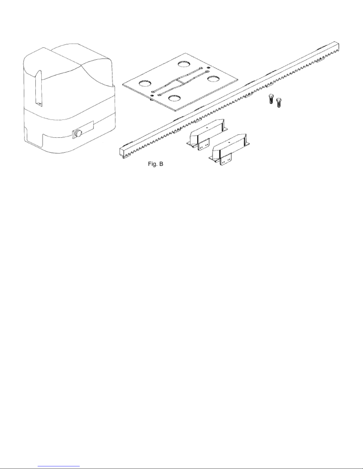
TECHNICAL FEATURES OF THE B2 SERIES
Art.P 400CNR Nylon rack;
Art.P-400CPS Foundation counter plate complete with screws
Art.P-350... Geared motor mod. Speed 2 - 5 - 8 including:
Art.S-350F300140 nr. 2 end limit-sliding blocks (only for SPEED 5-8)
MATERIALES PARA LAINSTALACION
Art.P 400CNR Cremallera de Nylon;
Art.P-400CPS Contraplaca de Cimentación con Tornillos;
Art.P-350.... Motorreductor Serie Speed 2 - 5 - 8. Consta de:
Art.S-350F300140 Dos excéntricas (o patines) de tope (solo para SPEED 5-8)
CONSIDERATIONS PRIOR TO INSTALLATION
CONSIDERACIONES PRELIMINARES A LA INSTALACION
Before you start installing check that:
• The gate wheels have been mounted to render the gate firm, that they are in god conditions and efficient;
• The sliding raid is free, straight and clean along its length and that there are stop pads at the ends;
• the top guide is in axis with the rail, that it is lubricated and gives the gate about 1 mm play.
Antes de llevar a cabo la instalación controlar que:
• Las ruedas de la verja hayan sido montadas de manera que la verja tenga estabilidad, se encuentren en buen estado y sean
eficientes;
• El carril de deslizamiento esté libre, recto y limpio en toda su longitud y que tenga los topes de parada en las extremidades;
• La guía superior esté en eje con el carril, esté lubrificada y permita un juego de aproximadamente 1 mm a la hoja.
Page 4
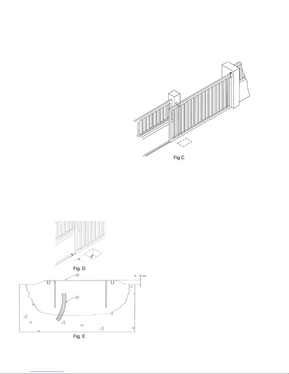
FINDING THE SITE
LOCALIZACION DE LA UBICACION
Choose a position that is identical to the dotted area.
Elegir una posicion análoga al area punteada.
PREPARING THE BASE
PREPARACION DE LA BASE
Dig comfortably wide foundations, at least 15 cm deep.
Protect the cables with a sheath.
1 foundation counter plates with fish-tail clamp manually
opening;
2 cables protection sheath;
Exavar los cimientos con una profundidad de unos 15 cm por lo
menos y bien ensaanchados.
Prever una funda protectora para los cables.
1 Contraplaca de cimentación con grapas que se pueden abrir
manualmente.
2 Envoltura protección cables.
Page 5
ANCHORING THE FOUNDATION COUNTER PLATES
FIJACION DE LA CONTRAPLACA DE CIMENTACION
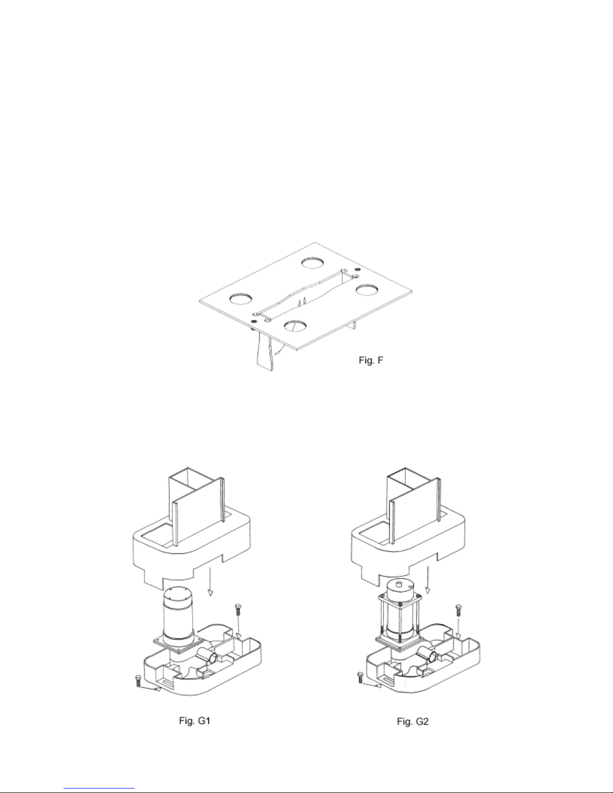
1.Once finished with the ditch, prepare the fundation counterplate by bending the clamps of the plate (see Fig. below) by the same spot
where the cones are jointed to fasten the operator with screws. Fill the ditch with cement; the counterplate has to be completely leveled
at 3/8" to 3/4"over the ground level and at a distance of 2 9/16" approximately from the gate. Use rack as indicated in Fig. B. Note: You
can also install the operator without the counterplate by using two expansion bolts on a concrete base but keeping the same measures
mentioned above.
1. Terminada la zanja, preparar la contraplaca de cimentación doblando las grapas de la placa, tal como muestra fig. F, por la misma
parte donde están los conos fileteados para fijar el motorreductor con tornillos. Llenar las zanjas con hormigón; la contraplaca tiene
que estar completamente plana, a unos 1 ó 2 cm. del nivel del suelo y a una distancia de 65 mm. aproximadamente de la verja; usar la
cremallera indicada en la fig. B.
Nota: También se puede instalar el motorreductor sin la contraplaca de cimentación, usando dos tornillos de expansión sobre una base
plana de hormigón, pero respetando las mismas medidas arriba indicadas.
ANCHORING THE GEARED MOTOR
FIJACIÓN DEL MOTORREDUCTOR
Page 6

Tighten the screws (as shown in fig G) on both sides of the geared motor. Carry all cables across the holes obtained from the base of
the foundation counter plate.
Apretar los tornillos (tal como se indica en la fig.G1 - G2 ) en ambos lados del motorreductor. Pasar todos los cables a través de los
agujeros existentes en la base de la contraplaca de cimentación.
FIXING THE RACK
FIJACIÓN DE LA CREMALLERA
1 – 2 mm
Fig. H
Fig. I
Once the gate has been drilled, fix the rack to it using 6.3 mm. self-threading screws.
Después de haber perforado la hoja, fijar la cremallera a la verja con tornillos con autorroscado que tengan un diámetro de 6.3 mm.
FIXING AND ADJUSTING THE END LIMIT SLIDING BLOCKS
(SPEED 5 - 8)
FIJACIÓN Y REGULACIÓN DE LOS PATINES DE FIN DE CARRERA
(SPEED 5 - 8)
Page 7

Position the blocks as shown in fig L, each one near the end of the rack. Moving the gate manually, position the blocks so
they make contact with the micro switch lever just before the end of the rail mechanical stop intervenes; now tighten the
screws.
Colocar los patines como se indica en la fig. L y cada uno de ellos cerca de una extremidad de la cremallera. Moviendo la
hoja manualmente, colocar los patines de manera que intervengan sobre la palanca del microinterruptor (palanca de
resorte colocada en la parte trasera del aparato) un poco antes de la intervención de los topes mecánicos del final del
carril; luego apretar los tornillos.
USE OF MANUAL UNLOCKING
UTILIZACIÓN DEL DESBLOQUEO MANUAL
ADJUST THE MECHANICAL FRICTION CLUTCH (SPEED 2 - 5)
AND THE ELECTRIC FRICTION CLUTCH (SPEED 8)
AJUSTE DEL EMBRAGUE ELÉCTRICO (SPEED 2 - 5)
Y MECÁNICO (SPEED 8)
The adjustment of friction is done during the micro-processor' s programming phase (collocated in main card MEC 10) in
which is possible to regulate: operation time, motor torque adjustment and the slowing down when the gate reaches the
end or when it is going to open. It is possible by the Encoder positioned under the motor' s cover, as shown in fig O.
El ajuste del embrague se realiza durante la fase de programación del microprocesador (presente en la ficha MEC 10).
Durante esta fase se regula el tiempo de trabajo, la resistencia del par motor y también la deceleración en fase de cierre
y la puesta en marcha, inicialmente decelerada, de la puerta corredera mediante el Encóder colocado bajo la tapa del
motor, tal como muestra la Fig. O.
Page 8

SPEED 5 SPEED 8
Fig. P
Fig. Q
The mechanical friction clutch of SPEED 5 can be modified with a screwdriver regulating the RCM trimmer as shown in
Fig. P; on the contrary the mechanical friction clutch of SPEED 8 can be regulated manually with a key included in the kit
of the geared motor as shown in fig Q.
El embrague mecánico en el SPEED 5 se regula maniobrando con un destornillador el trimmer de Regulación Par Motor,
tal como muestra la fig. P; por el contrario, en el SPEED 8 la regulación se efectúa de modo tradicional mediante la llave
suministrada junto con el motorreductor, tal como muestra la fig. Q.
Page 9

ELECTRICAL CONNECTIONS (SPEED 2 - 5 - 8)
CONEXIONES ELÉCTRICAS (SPEED 2 - 5 - 8)
To connect remove the casing from the geared motor, the electrical components stand and only for SPEED 2 the cover of
transformer, Fig. R. Carry all cables across the holes obtained from the foundation' s base counter plate and across the inferior
base of geared motor and
1. To the stabilization card positioned under the cover of the transformer for the SPEED 2;
2. To the principal card placed in the electrical components stand for SPEED 5 - 8.
Use cables with a minimum cross section of 1.5 mm2 for the power circuits and 0.5 mm2 for the control circuits.
Para realizar las conexiones eléctricas, sacar el cárter del motorreductor, el soporte componentes eléctricos y, sólo para
el SPEED 2, la tapa del transformador, fig. R. Introducir los cables de alimentación a través de los agujeros existentes en
la contraplaca de cimentación (cuando ésta se utilice); pasarlos a través del cuerpo inferior del motorreductor y
prepararlos para la conexión:
1. Con la ficha estabilizadora, colocada bajo la tapa del transformador para el SPEED 2.
2. Con la ficha de mando, situada en el soporte componentes eléctricos para el SPEED 5 y para el SPEED 8.
Emplear cables de una sección mínima de 1,5 mm2 para los circuitos de potencia y de 0.5 mm2 para los circuitos de
mando.
dispose them for the connection:
Page 10

Fig. U
Page 11

Fig. V
Page 12

TERMINAL BOARD CONNECTIONS
For Slider Cross Speed 2 MEC-10
110 V Terminals inside transformer housing.
1 – 2 12V DC supply terminal 1 + terminal 2 –
3 – 4 12V DC 6Ah dry battery input terminals 3 + terminal 4 - This battery guarantees power to
panel for 24 hours with panel in waiting state or 20 minutes with motor running (app. 30
maneuvers) BATTERY IS OPTIONAL.
5 – 6 12V DC OUTPUT max. 80W to power photocells, etc. Terminal 5 + Terminal 6 –
7 – 8 12V DC motor output max. 50W
9 – 10 used in MEC-20 only.
11 – 14 12V DC 20W output for flashing light. Terminal 11 + Terminal 1
12 – 14 12V DC 12W indicator light output. It is on from beginning of the opening until the gate is
completely closed. Terminal 12 + Terminal 14 –
13 – 14 12V DC 15W electric lock output. Terminal 13 + Terminal 14 –
15 – 17 Pedestrian push button input.
16 – 17 OPEN/CLOSE push button (step-by-step). Refer for operation to dip switch 3 & 4.
(normally open)
18 – 17 Stop push button. Stop gate in any direction.
19 – 17 SAFETY input. Photo cells etc.
20 – 17 Fixed safety edge input. During opening phase the gate will re-close for about 2 seconds.
During closing phase gate will reopen for about 2 seconds.
21 to 24 Factory connections for limit switch encoder.
(normally open)
(normally closed)
(normally closed)
(normally closed)
DIP SWITCH ADJUSTMENTS
1. ON when the gate is in operation a series of open/close commands activates the gate in the
following sequence OPEN - STOP - CLOSE - STOP -OPEN - STOP etc.
OFF function is determined by dip switch 3
2. ON photocell operates during open and closing.
OFF photocell operates only when gate is closing.
3. ON open/close push button will reverse gate in both directions.
OFF gate will only reverse in closing phase
4. ON enables automatic closure of gate.
OFF the gate will not close automatically
5 & 6 SLOWING DOWN (100% being total travel time)
OFF OFF 95% normal speed 5% at reduced speed
OFF ON 88% normal speed 12% at reduced speed
ON OFF 63% normal speed 37% at reduced speed
ON ON 50% normal speed 50% at reduced speed
Page 13

7 & 8 NOT IN USE
9 & 10 ELECTRONIC FRICTION ADJUSTMENT
The system is highly sensitive to any variation in speed of travel due to any obstructions.
Adjust as follows:
OFF OFF Maximum
ON OFF Medium maximum
OFF ON Medium minimum
ON ON Minimum
SETTING TRAVEL (LIMITS) TIME
1. Place JMP1 into “MEMO” bridge
2. Press OPEN/CLOSE push button and make sure that the first movement of gate is closing phase
(if you open gate slightly you can ensure easier that this happens). If gate travels wrong way reverse
motor polarity.
3. After gate having closed, in about 2 seconds the gate will open fully. Ensure that gate comes to a
"stop" you have installed.
4 Replace JMP1 into "NORMAL" bridge as your limits have now been set.
SETTING AUTO CLOSE TIME - REQUIRED ONLY IF AUTO
CLOSING IS NEEDED
(Time for which gate stays open before closing automatically)
1. Place JMP1 into "MEMO" bridge.
2. Press OPEN/CLOSE push button and make sure that the first movement of gate is closing phase
(if you open gate slightly you can ensure easier that this happens). If gate travels wrong way reverse
motor polarity.
3. After gate having closed, in about 2 seconds the gate will open fully. Ensure that gate comes to a
"stop" you have installed.
4. Now the gate is fully opened wait for the period of time you want the gate to stay opened before
closing automatically and then push OPEN/CLOSE push button.
5. Replace JMP1 into “NORMAL” bridge as your limits and auto close times have now been set.
TO CHANGE ABOVE TIMES PLACE JMP3 INTO RESET POSITION FOR TWO TO THREE SECONDS ONLY AND THEN JMP1
INTO “MEMO” AND FOLLOW ABOVE INSTRUCTIONS
FOR ANY FURTHER INFORMATION PLEASE CONTACT OUR TECHNICIANS AT 305-691-7711
ALL CARE HAS BEEN TAKEN IN COMPILING THIS SET OF INSTRUCTIONS HOWEVER AFW ACCESS SYSTEMS
TAKES NO RESPONSIBILITY FOR ANY ERRORS OR OMISSIONS.
Page 14

TERMINAL BOARD CONNECTIONS
For Slider Cross-Speed 5 – Speed 8
1 – 2 110 V AC 50 Hz Power Supply
5 – 6 – 7 Motor Terminals: 5 – common, 6 – opening, 7 – closing. Capacitor between terminals 6 –
7
3 – 4 110 V 50 W Max. FLASHING OUTPUT. The signal supplied is already modulated for
direct use. Flashing frequency increases slightly in closing phase.
8 – 9 24 V AC 3 W output for GATE OPEN indicator – the indicator lights up when gate is
completely opened and switches off when closing is started.
10 – 11 24 V AC 10 W output for power supply for photocells, etc.
12 – 14 OPEN LIMIT SWITCH input
13 – 14 CLOSE LIMIT SWITCH input
15 – 14 FIXED SAFETY EDGE input
safety edge shuts down gate movement temporarily and activates partial reopen app. 20
cm (9”) to enable removal of obstacle. 14 – common.
16 – 20 PHOTOCELL or other SAFETY DEVICE input
activated, the gate is shut down temporarily until the detected obstruction is removed
(depending on setting of dip switch 1). During closing, the gate will stop and re-open
completely. 20 – common.
17 – 20 OPEN/CLOSE push button input
20 – common.
18 – 20 PEDESTRIAN push button input
with limited stroke of app. 1 m (39”) opening for pedestrian access only. 20 – common.
19 – 20 STOP push button input
The gate opens automatically when reactivated. 20 – common.
21 – 22 AERIAL input. 21 – core 22 – shield
23 – 24 2nd RADIO CHANNEL output.
NOTE ALL
LOGIC ADJUSTMENTS – TRIMMERS.
T.L. Operation Time Adjustment – from 0 to 180 seconds.
T.C.A. Automatic Closure Time – from 0 to 120 seconds.
R.C.M. Motor Torque Adjustment
NORMALLY CLOSED
MUST BE EARTHED.
(normally closed)
(normally closed)
(normally closed).
(normally open).
(normally open).
(normally closed).
CONTACTS MUST BE BRIDGED IF NOT USED. THE UNIT
14 – common.
14 – common.
Operates only during closing phase. The
(normally closed)
For functions refer to dip switch 1 & 2.
Same as Open/Close push button but
When activated, the gate movement stops.
. When this device is
DIP SWITCH ADJUSTMENTS
1. ON When the gate is in operation, a series of Open/Close commands activates the gate in the
following sequence. OPEN – CLOSE – OPEN – CLOSE – OPEN – etc.
OFF When the gate is in operation, a series of Open/Close commands activates the gate in the
following sequence. OPEN – STOP - CLOSE – STOP – OPEN – STOP - CLOSE – STOP
- OPEN – STOP - etc.
Page 15

2. ON You can reverse directions both ways
OFF You can reverse direction only when the gate is closing.
3. ON During opening phase, the activation of photocell will shut down the gate movement until
the detected obstacle is removed. During closure, the activation of photocell will cause
the gate movement to shut down and re-open.
OFF During opening phase, the activation of photocell will have no effect. During closing
phase, the activation of photocell will operate as above (ON)
4. ON Enable automatic closure of gate as set by trimmer T.C.A.
OFF The gate will not close automatically.
FOR ANY FURTHER INFORMATION PLEASE CONTACT OUR TECHNICIANS AT 305-691-7711
ALL CARE HAS BEEN TAKEN IN COMPILING THIS SET OF INSTRUCTIONS HOWEVER AFW ACCESS SYSTEMS
TAKES NO RESPONSIBILITY FOR ANY ERRORS OR OMISSIONS.
USE
USO
Geared motors SPEED 2 - 5 - 8 are designed to move horizontally sliding gates with a maximum weight of 400 Kg (for the
SPEED 2), of 500 Kg (for the SPEED 5) and of 800 Kg (for the SPEED 8).
It is absolutely forbidden to use the device for any other purposes or under circumstances different from those mentioned.
The electronic unit installed (which must have a built in electric friction) normally permits you to select the following
functions:
automatic:
semi-automatic:
It could appen that there is not electricity, in this case you can operate the gate manually but first you have to "unlock" it.
Remember that this is an automatic device which is powered by electricity, consequently use with care. In particular,
remember:
• do not touch it with wet hands and/or wet or bare feet
• turn the electricity off before opening the control box and/or geared motor
• do not touch the motor unless you are certain it is cold
• only operate the door when it is completely visible
• keep out of the doorís range of action if it is moving: wait until it has stopped
• do not let children or animals play near the door
• do not let children, or incapable people, use the remote control or other operating devices
• carry out routine maintenance
• in the case of a failure, turn the electricity off and work the door manually only if it is possible and safe to do so. Refrain
from touching the door and call an authorised technician.
Los motorreductores SPEED 2-5-8 han sido proyectados para mover la verjas de deslizamiento horizontal con hojas que
tengan un peso máximo de 400 kg (para el mod. Speed 2), 800 Kg (para el mod. Speed 5) y 800 Kg (para el mod. Speed
8). Se recuerda explícitamente que está prohibido usar el aparato para fines diversos o en circunstancias diferentes de
las mencionadas.
Normalmente, la centralita instalada permite seleccionar el funcionamiento:
automático:
semiautomático:
En caso de faltar la corriente eléctrica se puede pasar a la gestión manual interviniendo antes sobre el dispositivo de
desbloqueo.
Se recuerda que nos hallamos ante un dispositivo automático alimentado por corriente eléctrica, por lo tanto, debe usarse
con precaución. En particular se recomienda:
• No tocar el aparato con la manos mojadas y/o con los pies mojados o descalzos;
• Desconectar la corriente antes de abrir la caja de mandos y/o el accionador;
• No tirar del cable de alimentación para desconectar la toma de la corriente;
• No tocar el motor si no est· seguro que se haya enfriado completamente;
a command pulse will open and shut the gate;
a command pulse will open or shut the gate;
a un impulso del mando se abre y cierra la verja.
a un impulso del mando se abre o cierra la verja.
Page 16

• Mover la verja sólo cuando sea completamente visible;
• Mantenerse fuera del radio de acción de la verja, si ésta se halla en movimiento, esperar hasta que se haya detenido;
• No dejar que niños o animales jueguen cerca de la verja;
• No dejar que niños o personas incapacitadas usen el mando a distancia u otros dispositivos de accionamiento;
• Realizar un mantenimiento periódico.
MAINTENANCE
MANTENIMIENTO
The geared motors in the Speed Series need very little maintenance. However, to ensure it always works properly the
gate has to be in good condition: hence we shall describe briefly what you need to do to keep your overhead garage door
efficient.
ATTENTION: no one, except the person who services the equipment (who must be a specialized technician), should be
able to command the automatism during servicing. Consequently, it is advisable to turn the electricity off at the mains also
to avoid possible electric shocks. If the electricity has to be on for certain checks, check or disable all command devices
(remote controls, push button panels, etc.) except for the device being used by the maintenance person.
Routine maintenance:
Each of the following operations must be carried out when the need arises and, in all cases, every 6 months.
• Lubricate the gate wheels and make sure the counterweights slide easily
• Check how the safety devices are working (pneumatic edge, torque limiter, etc.). They must be efficient in the case of
danger and trigger as set during installation.
Extraordinary maintenance or breaks
If there are any complex jobs that need doing on electromechanical parts, it is advisable to remove the relative part so that
the repairs can be carried out in the workshop by parent company technicians or their authorised technicians.
Los Operadores SPEED2 - 5 - 8 necesita poco mantenimiento. Sin embargo, el estado de conservación de la verja
influye en su correcto funcionamiento; por ello describiremos brevemente cuáles son las operaciones que se deben
realizar para mantener una verja en perfectas condiciones.
ATENCION: Nadie a excepción de la persona encargada del mantenimiento, que deber· ser un técnico especializado,
podrá hacer uso los mandos de la verja automática durante las operaciones de mantenimiento. Por lo tanto, se
recomienda desconectar la corriente eléctrica, evitando de ese modo el peligro de shock eléctricos. Al contrario, si la
corriente eléctrica tuviera que estar presente durante algunas comprobaciones, se recomienda controlar o desconectar
cada uno de los dispositivos de mando (mando a distancia, caja de pulsadores, etc.) a excepción del dispositivo usado
por la persona que realiza el mantenimiento.
Mantenimiento ordinario:
Cada una de las siguientes operaciones se debe realizar cada vez que sea necesario y como prevención cada 6 meses.
• Lubrificar (con aceitero) las ruedas de deslizamiento del porton.
• Comprobar la limpieza y la estabilidad de la cremallera.
Sistema de automatización:
• Comprobar el funcionamiento de los dispositivos de seguridad (fotocélulas, costa neumática, etc.) con los tiempos y
modos descritos por los fabricantes.
Mantenimiento extraordinario:
Si fueran necesarias intervenciones no banales sobre partesmecánicas se aconseja quitar el motorreductor para permitir
una reparación en el taller por parte de los técnicos de la casa madre o por personal autorizado por la misma.
 Loading...