

Page 1
MANUALE D’USO E MANUTENZIONE
USE AND MAINTENANCE MANUAL
BEDIENUNGS - UND WARTUNGSANLEITUNG
MANUEL D’EMPLOI ET D’ENTRETIEN
MANUAL DE USO Y MANTENIMIENTO
MANUAL DO UTILIZADOR E MANUTENÇÃO
RBLO Series
Barriera Automatica
Automatic Barrier
Automatische Schranken
Barrière Automatique
Barrera Automatica
Barreira Automática
D-MNL0RBLO 11-06-2018 - Rev.17
IT - Istruzioni originali
Via Enrico Fermi, 43 - 36066 Sandrigo (VI) Italia
Tel +39 0444 750190 - Fax +39 0444 750376 - info@tauitalia.com - www.tauitalia.com
RBLO Series
1
Page 2

Italiano
I dati riportati nel presente manuale sono puramente indicativi. La TAU si riserva il diritto di modicarli in qualsiasi momento.
La Casa costruttrice si riserva il diritto di apportare modiche o miglioramenti al prodotto senza alcun preavviso. Eventuali imprecisioni o errori
riscontrabili nel presente fascicolo, saranno corretti nella prossima edizione.
All’apertura dell’imballo vericare che il prodotto sia integro. Riciclare i materiali secondo la normativa vigente.
L’installazione del prodotto dovrà essere effettuata da personale qualicato. La Ditta costruttrice Tau declina ogni responsabilità per
danni derivanti a cose e/o persone dovuti ad un’eventuale errata installazione dell’impianto o la non messa a Norma dello stesso
secondo le vigenti Leggi (vedi Direttiva Macchine).
AVVERTENZE E ISTRUZIONI PER L’INSTALLATORE
Tau si congratula per la scelta del prodotto e vi invita a leggere con molta attenzione queste pagine.
Al ne di renderle semplici, le istruzioni sono state impaginate seguendo l’ordine delle varie fasi d’installazione dell’impianto.
Leggere attentamente le istruzioni prima di procedere all’installazione, in quanto forniscono importanti indicazioni concernenti la
sicurezza, l’installazione, l’uso e la manutenzione.
Tutto quello che non è espressamente previsto nel presente manuale NON è permesso. Consultare la TAU srl per ogni cosa non indicata.
Usi non indicati, infatti, potrebbero essere causa di danni al prodotto stesso e mettere in pericolo persone, animali e/o cose.
L’installazione deve essere eseguita da personale qualicato, professionalmente competente.
L’installazione, i collegamenti elettrici e le regolazioni devono essere effettuati nell’osservanza della Buona Tecnica e in ottemperanza alle
norme vigenti.
Prima di iniziare l’installazione vericare l’integrità del prodotto.
Non installare il prodotto in ambiente e atmosfera esplosivi.
Prima di installare l’automazione, apportare tutte le modiche strutturali relative alla realizzazione dei franchi di sicurezza ed alla protezione o
segregazione di tutte le zone di schiacciamento, cesoiamento, convogliamento e di pericolo in genere. Vericare che la struttura esistente abbia
i necessari criteri di robustezza e stabilità. Per la messa a punto della coppia massima del motoriduttore, attenersi alle normative in vigore (per
l’Europa consultare le norme EN 12341-1 e EN 12635).
L’installazione del motoriduttore, ad eccezione dei modelli interrati, deve essere realizzata sopra il livello del pavimento, al ne di evitare rischi
di allagamento.
I dispositivi di sicurezza (fotocellule, coste sensibili, stop di emergenza, ecc.) devono essere installati tenendo in considerazione: le normative
e le direttive in vigore, i criteri della Buona Tecnica, l’ambiente di installazione, la logica di funzionamento del sistema e le forze sviluppate dalla
porta o cancello motorizzati.
Scegliere percorsi brevi per i cavi. Tenere separati i cavi di potenza dai cavi di comando.
Quantunque il motoriduttore possa essere dotato di tutti i dispositivi di sicurezza si consiglia caldamente di tenere fuori della portata di bambini o
di persone inabili ogni dispositivo in grado di comandare l’apertura del cancello e che possa inavvertitamente essere usato senza sorveglianza.
Applicare le segnalazioni previste dalle norme vigenti per individuare le zone pericolose. Ogni installazione deve riportare in modo visibile l’indicazione dei dati identicativi degli organi automatizzati.
Prima di collegare l’alimentazione elettrica accertarsi che i dati di targa siano rispondenti a quelli della rete di distribuzione elettrica.
Prevedere sulla rete di alimentazione un interruttore/sezionatore onnipolare con distanza d’apertura dei contatti uguale o superiore a 3 mm.
Vericare che a monte dell’impianto elettrico vi siano un interruttore differenziale e una protezione di sovracorrente adeguati (interruttore magnetotermico C6).
Non lavare l’automazione con idropulitrice.
Collegare l’automazione ad un efcace impianto di messa a terra eseguito come previsto dalle vigenti norme di sicurezza.
Il costruttore dell’automazione declina ogni responsabilità qualora vengano installati elementi incompatibili ai ni della sicurezza e del buon
funzionamento. Per l’eventuale riparazione o sostituzione dei prodotti, dovranno essere utilizzati esclusivamente ricambi originali.
L’installatore deve fornire tutte le informazioni relative al funzionamento automatico, manuale e di emergenza della struttura automatizzata, e
consegnare all’utilizzatore dell’impianto le istruzioni per l’uso.
Consigliamo di riporre tutta la documentazione relativa all’impianto all’interno o nelle immediate vicinanze della centralina.
English
The data described in this handbook are purely a guide. TAU reserves the right to change them in any moment.
The manufacturer reserves the right to modify or improve products without prior notice. Any inaccuracies or errors found in this handbook will
be corrected in the next edition.
When opening the packing please check that the product is intact. Please recycle materials in compliance with current regulations.
This product may only be installed by a qualied tter. The manufacturer declines all liability for damage to property and/or personal
injury deriving from the incorrect installation of the system or its non-compliance with current law (see Machinery Directive).
WARNINGS AND INSTRUCTIONS FOR FITTERS
Congratulations on choosing this Tau product. Please read this handbook carefully.
For the sake of simplicity, the instructions are listed in order of installation.
Please read these instructions carefully before installing the product as they contain important information concerning safety, installation, use and maintenance.
Anything not expressly specied in this handbook is FORBIDDEN. Contact TAU srl for information regarding any points which may not have
been specied in the present manual.
Operations not indicated in these instructions may damage the product and put people, animals and/or and property at risk.
The equipment should be installed only by trained and qualied personnel.
Installation, electrical connections and adjustments must be made according to the rules of good workmanship and current standards.
Before beginning installation, make sure the product is undamaged.
Do not install the product in explosive environments.
Prior to installing the automation, make all structural modications in order to ensure safety distances and protect and segregate areas in which
people may be exposed to the risk of crushing, shearing, dragging or similar dangers. Make sure the existing structure is sufciently sturdy
and stable. Observe current legislation when adjusting maximum gearmotor torque (in Europe consult EN 12341-1 and EN 12635 standards).
Apart from buried models, the gearmotor must be installed above ground level in order to prevent damage deriving from ooding.
The safety devices (photocells, sensitive edges, emergency stop devices, etc.) must be installed according to current legislation and directives,
the rules of good workmanship, the installation area, the operating logic of the system and the forces developed by the powered door or gate.
Choose short routes for the cables. Keep power cables separate from control cables.
Though the gearmotor is tted with various safety devices, we strongly recommend keeping all unattended devices capable of opening the gate
out of the reach of children or unable adults.
Fit the signs required by current regulations for identifying dangerous areas. Each installation must show the identication data of the automated
2
RBLO Series
Page 3

devices in a visible place.
Before connecting to the power supply, make sure the data on the rating plate correspond to the mains power supply.
Fit a multipole switch/knife switch on the power supply network with contacts opening distance of at least 3 mm.
Make sure there is a suitable circuit breaker and overcurrent protection device (thermal-magnet breaker C6) upline from the electrical system.
It is strictly forbidden to use high pressure water cleaners or jets of water in general to clean the automation.
Connect the automation to an efcient earth system compliant with current safety standards.
The manufacturer declines all liability if incompatible safety and components are installed. Only use original spare parts to repair or replace the
product.
The tter must provide all the information relative to the automatic, manual and emergency operation of the automated unit, and give the user
the operating instructions.
Keep all the documents concerning the system inside or near the central control unit.
Deutsch
Die beschriebenen Daten in der vorliegenden Betriebsanleitung sind rein indikativ. TAU behält sich vor, diese in jedem Moment zu modizieren.
Der Hersteller behält sich das Recht vor, ohne vorherige Benachrichtung Änderungen oder Verbesserungen am Produkt anzubringen. Ungenauigkeiten oder Fehler, die in der vorliegenden Ausgabe festgestellt werden, werden in der nächsten Ausgabe berichtigt.
Beim Öffnen der Verpackung prüfen, dass das Produkt keine Schäden aufweist. Die Materialien nach den gültigen Vorschriften recyclen.
Die Installation des Produktes muss von Fachpersonal ausgeführt werden. Die Herstellerrma TAU übernimmt keinerlei Haftung für
Personen- und/oder Sachschäden aufgrund einer falschen Installation der Anlage oder der Nichtkonformität derselben mit den gültigen Gesetzen (siehe Maschinenrichtlinie).
HINWEISE UND ANWEISUNGEN FÜR DEN INSTALLATEUR
Tau gratuliert Ihnen zur Wahl dieses Produkts und bittet Sie, diese Seiten sehr aufmerksam zu lesen.
Um die Anweisungen einfach zu machen, wurden sie in der Reihenfolge der verschiedenen Installationsphasen der Anlage verfasst.
Die Anweisungen vor der Installation genau lesen, da sie wichtige Hinweise mit Bezug auf Sicherheit, Installation, Bedienung und
Wartung liefern.
Alles nicht ausdrücklich in diesen Anleitungen vorgesehene ist UNZULÄSSIG. Wenden Sie sich für alles nicht angegebene an die Firma TAU
srl.
Ein nicht angegebener Gebrauch könnte Schäden am Produkt verursachen und Personen, Tiere und/oder Gegenstände in Gefahr bringen.
Die Installation muss von beruich kompetentem Fachpersonal ausgeführt werden.
Installation, elektrische Anschlüsse und Einstellungen sind unter Beachtung der Fachtechnik und der gültigen Vorschriften auszuführen.
Das Produkt vor der Installation auf Schäden überprüfen.
Das Produkt nicht in EX-Umgebung bzw. EX-Atmosphäre installieren.
Vor der Installation der Automatisierung alle strukturellen Änderungen für das Vorhandensein der Sicherheitsabstände und den Schutz aller
Bereiche ausführen, in denen Quetsch-, Schnitt- und Mitnehmgefahr und Gefahren allgemein bestehen. Prüfen, ob die vorhandene Struktur die
erforderliche Robustheit und Stabilität besitzt. Für die Einstellung des maximalen Drehmoments des Getriebemotors sind die gültigen Vorschriften zu beachten (für Europa siehe die Normen EN 12341-1 und EN 12635).
Die Installation des Getriebemotors muss, Unterurmodelle ausgenommen, über der Bodenhöhe erfolgen, um Überschwemmungsgefahr zu
vermeiden.
Sicherheitsvorrichtungen (Fotozellen, Sicherheitsleisten, Notstop usw.) müssen unter Berücksichtigung des folgenden installiert werden: gültige
Vorschriften und Verordnungen, korrekte Fachtechnik, Installationsumgebung, Betriebslogik des Systems und Kräfte, die vom motorbetriebenen Tor entwickelt werden.
Kurze Strecken beim Verlegen der Kabel wählen. Leistungskabel von Steuerkabeln getrennt halten.
Auch wenn der Getriebemotor mit allen Sicherheitsvorrichtungen ausgestattet werden kann, empfehlen wir, Vorrichtungen zur Betätigung eines
Tors, die ohne Überwachung zufällig benutzt werden könnten, außer der Reichweite von Kindern oder Personen mit Handicaps zu halten.
Zur Kennzeichnung von Gefahrenbereichen die laut gültigen Vorschriften vorgesehenen Beschilderungen anbringen. An jeder Installation müssen die Kenndaten der automatisierten Elemente sichtbar angegeben sein.
Vor dem Anschluss der Stromversorgung ist sicher zu stellen, dass die Kenndaten mit jenen des Stromnetzes übereinstimmen.
Am Versorgungsnetz einen allpoligen Schalter/Trennschalter mit Öffnungsabstand der Kontakte von oder über 3 mm vorsehen.
Prüfen, dass vor der elektrischen Anlage ein Differentialschalter und ein geeigneter Überstromschutz (magnetothermischer Schalter C6) vorhanden sind.
Nicht mit einem Hochdruckreiniger reinigen.
Die Automatisierung an eine wirksame Erdungsanlage anschließen, die nach den gültigen Sicherheitsvorschriften ausgeführt ist.
Der Hersteller der Automatisierung übernimmt keinerlei Haftung, falls Bestandteile installiert werden, die – was Sicherheit und korrekten Betrieb
betrifft – nicht kompatibel sind. Zur Reparatur oder zum Ersatz der Produkte dürfen ausschließlich Originalersatzteile verwendet werden.
Der Installateur hat alle Auskünfte über den automatischen und manuellen Betrieb und den Notbetrieb der automatisierten Struktur zu liefern
und muss dem Benutzer der Anlage die Bedienungsanweisungen aushändigen.
Wir empfehlen, alle Unterlagen der Anlage in der Steuerzentrale oder in ihrer unmittelbaren Nähe aufzubewahren.
Français
Les données décrites dans ce manual sont purement indicatives. La TAU se réserve le droit de les modier à n’importe quel moment.
Le Constructeur se réserve le droit d’apporter des modications ou des améliorations au produit sans aucun préavis. Les éventuelles imprécisions ou erreurs présentes dans ce fascicule seront corrigées dans la prochaine édition.
À l’ouverture de l’emballage, vérier que le produit est intact. Recycler les matériaux suivant les normes en vigueur.
L’installation du produit devra être effectuée par du personnel qualié. Tau décline toute responsabilité pour les dommages aux
choses et/ou personnes dus à une éventuelle installation erronée de l’automatisme ou à la non-mise aux normes suivant les lois en
vigueur (voir Directive Machines).
AVERTISSEMENTS ET INSTRUCTIONS POUR L’INSTALLATEUR
Tau vous félicite de votre choix et vous invite à lire très attentivement les pages qui suivent.
An de faciliter la compréhension, l’ordre de présentation des instructions suit celui des différentes phases d’installation de l’automatisme.
Lire attentivement les instructions avant de procéder à l’installation, dans la mesure où elles fournissent des indications importantes
concernant la sécurité, l’installation, l’emploi et la maintenance.
Tout ce qui n’est pas expressément prévu dans ce manuel N’EST PAS permis. Consulter TAU srl pour tout ce qui n’est pas indiqué.
Les utilisations non indiquées, en effet, pourraient provoquer des dommages au produit et mettre en danger les personnes, les animaux et/ou
les choses.
L’installation doit être effectuée par du personnel qualié, professionnellement compétent.
RBLO Series
3
Page 4

L’installation, les connexions électriques et les réglages doivent être effectués dans les règles de l’art en respectant les normes en vigueur.
Avant de commencer l’installation, vérier l’intégrité du produit.
Ne pas installer le produit dans un environnement et une atmosphère explosifs.
Avant d’installer l’automatisme, apporter toutes les modications structurelles relatives à la réalisation des espaces de sécurité et à la protection ou à l’isolement de toutes les zones d’écrasement, cisaillement et de danger en général. Vérier que la structure existante possède la
robustesse et la stabilité nécessaires. Pour le réglage du couple maximum du motoréducteur, respecter les normes en vigueur (pour l’Europe
consulter les normes EN 12341-1 et EN 12635).
L’installation du motoréducteur, à l’exception des modèles enterrés, doit être réalisée au-dessus du niveau du sol an d’éviter les risques
d’inondation.
Les dispositifs de sécurité (photocellules, barres palpeuses, arrêt d’urgence, etc.) doivent être installés en tenant compte : des normes et des
directives en vigueur, des règles de l’art, du site d’installation, de la logique de fonctionnement du système et des forces générées par la porte
ou le portail motorisés.
Choisir des parcours brefs pour les câbles et maintenir les câbles de puissance séparés des câbles de commande.
Malgré tous les dispositifs de sécurité qui peuvent équiper l’automatisme, il est vivement conseillé de maintenir hors de portée des enfants
ou de personnes inaptes tout dispositif en mesure de commander l’ouverture du portail et qui, par mégarde, pourrait être utilisé sans surveil-
lance.
Appliquer les signalisations prévues par les normes en vigueur pour identier les zones dangereuses. Chaque installation doit reporter de
manière visible, l’indication des données d’identication des organes automatisés.
Avant de connecter l’alimentation électrique, s’assurer que les données de la plaque correspondent à celles du secteur de distribution électrique. Prévoir sur le secteur d’alimentation un interrupteur/sectionneur omnipolaire avec distance d’ouverture des contacts égale ou supérieure
à 3 mm.
Vérier qu’il y a en amont de l’automatisme un interrupteur différentiel et une protection contre la surcharge adéquats (interrupteur magnétothermique C6).
Ne pas nettoyer à jet d’eau à haute pression.
Raccorder l’automatisme à une installation efcace de mise à la terre effectuée suivant les prescriptions des normes de sécurité en vigueur.
Le constructeur de l’automatisme décline toute responsabilité en cas d’installation de composants incompatibles en matière de sécurité et de
bon fonctionnement. Pour toute réparation ou pour tout remplacement des produits, il faudra utiliser exclusivement des pièces de rechange
originales.
L’installateur doit fournir toutes les informations relatives au fonctionnement automatique, manuel et d’urgence de la structure automatisée et
remettre à l’utilisateur de l’automatisme le mode d’emploi.
Nous conseillons de conserver toute la documentation relative à l’installation à l’intérieur de l’armoire de commande ou à proximité
immédiate.
Español
Los datos describidos en este manual son puramente indicativos. La TAU se reserva el derecho de modicarlos en cualquier momento.
El Fabricante se reserva el derecho de modicar o actualizar el producto sin aviso previo. Posibles imprecisiones o errores en este manual
serán corregidos en la próxima edición.
Cuando abra el embalaje, controle que el producto esté íntegro. Recicle los materiales según la normativa vigente.
La instalación del producto tiene que ser efectuada por personal cualicado. El Fabricante Tau no se asume ninguna responsabilidad
por lesiones a personas o averías a cosas causadas por una instalación incorrecta del equipo o la por la inobservancia de la normativa vigente (véase Directiva de Máquinas).
ADVERTENCIAS E INSTRUCCIONES PARA EL INSTALADOR
Tau le agradece por la elección del producto y le invita a leer con mucha atención estas páginas.
A n de simplicar su uso, las instrucciones han sido compaginadas siguiendo el orden de las diferentes etapas de instalación del sistema.
Lea con atención las instrucciones antes de proceder con la instalación, puesto que suministran importantes indicaciones sobre la
seguridad, instalación, uso y mantenimiento.
Todo aquello que no está expresamente previsto en este manual NO está permitido. Consulte con TAU srl para cualquier cosa que no esté
indicada.
En efecto, los usos no previstos podrían causar averías al producto y ser peligrosos para las personas, animales o cosas.
La instalación debe ser hecha por personal cualicado y experto.
La instalación, las conexiones eléctricas y las regulaciones deben ser efectuadas correctamente y respetando las normas vigentes.
Antes de empezar la instalación, controle la integridad del producto.
No instale el producto en locales con atmósfera explosiva.
Antes de instalar la automatización, realice todas las modicaciones estructurales relativas a la realización de las distancias de seguridad y
a la protección o separación de todas las zonas de aplastamiento, corte y peligro en general. Controle que la estructura existente posea los
criterios necesarios de robustez y estabilidad. Para poner a punto el par máximo del motorreductor, aténgase a las normativas en vigor (para
Europa consulte las normas EN 12341-1 y EN 12635).
La instalación del motorreductor, menos en el caso de los modelos enterrados, tiene que efectuarse por encima del nivel del pavimento para
evitar posibles inundaciones.
Los dispositivos de seguridad (fotocélulas, bordes sensibles, botón de parada de emergencia, etc.) se deben instalar teniendo en cuenta: las
normativas y directivas vigentes, los criterios de la buena técnica, el entorno de instalación, la lógica de funcionamiento del sistema y las fuerzas desarrolladas por la puerta o cancela motorizadas.
Escoja recorridos cortos para los cables. Mantenga separados los cables de potencia de los cables de control.
Aunque el motorreductor disponga de todos los dispositivos de seguridad, se aconseja mantener fuera del alcance de los niños o de personas incapacitadas cualquier dispositivo capaz de controlar la apertura de la cancela y que pueda utilizarse de forma inadvertida sin vigilancia.
Aplique las señalizaciones previstas por las normas vigentes para señalar las zonas peligrosas. Cada instalación debe tener a la vista la indicación de los datos de identicación de los componentes automatizados.
Antes de conectar la alimentación eléctrica, controle que las características nominales correspondan a aquellas de la red de distribución eléctrica.
Prevea en la red de alimentación un interruptor omnipolar de 3 o más mm de apertura de los contactos.
Controle que antes de la instalación eléctrica haya un interruptor diferencial y un dispositivo de protección de sobrecorriente adecuados (interruptor magnetotérmico C6).
No limpiar con hidrolimpiadora.
Conecte la automatización a una instalación de puesta a tierra ecaz y que respete las normas de seguridad vigentes.
El fabricante de la automatización no se asume ninguna responsabilidad si se instalan componentes incompatibles para la seguridad y el funcionamiento correcto. Para una posible reparación o sustitución de los productos, use sólo recambios originales.
El instalador debe suministrar todas las informaciones relativas al funcionamiento automático, manual y de emergencia de la estructura automatizada, y entregar al usuario de la instalación las instrucciones para su uso.
Se aconseja guardar toda la documentación de la instalación en el interior o cerca de la central.
4
RBLO Series
Page 5

Português
Os dados descritos neste manual são puramente indicativos. A TAU reserva-se o direito de o modicar a qualquer momento.
O fabricante reserva-se o direito de modicar ou actualizar o produto sem aviso prévio. Possíveis imprecisões ou erros no presente manual
serão corrigidos na próxima edição/revisão.
Ao abrir a embalagem certique-se que o produto está intacto. Recicle os materiais segundo as normas em vigor.
Este produto só pode ser instalado por um técnico qualicado. O fabricante TAU declina qualquer responsabilidade por danos corporais ou materiais resultantes de uma eventual instalação incorrecta do equipamento ou a não conformidade com a norma vigente (Ver Directiva de Máquinas).
ADVERTÊNCIAS E INSTRUÇÕES PARA O INSTALADOR
Parabéns por escolher um produto TAU. Por favor, leia atentamente as instruções.
De modo a simplicar o processo, o presente documento foi elaborado tendo em conta a ordem das várias fases do processo de instalação.
Leia atentamente as instruções antes de proceder à instalação, na medida em que fornecem indicações importantes relativas à segurança, à instalação, à utilização e à manutenção.
Tudo o que não está expressamente previsto no presente documento é considerado como NÃO permitido. Em caso de dúvida, consultar a TAU srl.
Aplicações e utilizações não indicadas no presente documento podem provocar danos no produto, além de representar uma fonte de perigo
para pessoas, animais e bens materiais.
A instalação deve ser executada por pessoal qualicado e prossionalmente competente.
A instalação, ligações eléctricas e ajustes devem ser realizados em conformidade com as boas práticas e em conformidade com as normas vigentes.
Antes de proceder à instalação, vericar a integridade do produto.
Não instalar o produto em ambientes explosivos.
Antes de proceder à instalação, execute todas as modicações estruturais relacionadas com as distâncias de segurança e com a protecção
ou segregação de todas as zonas onde exista perigo de esmagamento, arrastamento, cisalhamento ou outros perigos em geral. Vericar se
a estrutura existente possui a robustez e a estabilidade necessárias. Ao ajustar o binário máximo desenvolvido pelo motorredutor, respeite as
normas em vigor (para países europeus, consultar as normas EN12341-1 e EN12635).
A instalação do motorredutor, com excepção dos modelos enterrados, deve ser realizada acima do nível do pavimento de modo a prevenir
danos relacionados com inltrações no equipamento.
Os dispositivos de segurança (fotocélulas, arestas sensíveis, dispositivos de paragens de emergência, etc.) devem ser instalados tendo em
consideração as normas e directivas em vigor, as boas práticas, o ambiente onde se executa a instalação, a logica de funcionamento do sistema e a força desenvolvida pela automação.
Escolha os percursos mais curtos para a cablagem e mantenha os cabos de potência separados dos cabos de comando.
Embora a automação possa ser equipada com todos os dispositivos de segurança, recomenda-se que mantenha fora do alcance de crianças ou
pessoas com deciência, qualquer dispositivo capaz de controlar a abertura do portão e que possa inadvertidamente ser usado sem supervisão.
Aplicar a sinalização prevista nas normas vigentes de modo a identicar zonas de perigo. Cada instalação mostrar de forma visível todos os
dados identicativos dos componentes automatizados.
Antes de ligar a alimentação à rede eléctrica, vericar se as características técnicas do automatismo correspondem às da rede eléctrica.
Vericar a existência de um disjuntor omnipolar, com uma distância de abertura entre contactos igual ou superior a 3mm no circuito de alimentação da automação.
Vericar se a montante da instalação existe um disjuntor diferencial e uma protecção adequada contra sobrecargas eléctricas. Recomendase um disjuntor magnetotermico C6.
Não lavar com máquinas de alta pressão.
Assegurar que o aterramento eciente do sistema (ligação “terra”) conforme as boas práticas e as normas vigentes de segurança.
O fabricante do automatismo declina qualquer responsabilidade caso de instalação de componentes incompatíveis em termos de segurança e bom
funcionamento. Para eventual reparação ou substituição dos produtos, devem ser utilizadas unicamente peças de substituição originais TAU.
O instalador deve fornecer toda a informação em relação à operação manual do sistema em caso de emergência ou falha no fornecimento
de energia eléctrica, e entregar ao utilizador nal o “Manual do Utilizador” que acompanha o produto.
Aconselha-se que a documentação relacionada com o sistema esteja guardada no interior ou na proximidade da caixa de protecção da unidade de controlo.
DESCRIZIONE / DESCRIPTION / BASCHREIBUNG / DESCRIPTION / DESCRIPCIÓN / DESCRIÇÃO
Le barriere della serie RBL sono di tipo veloce, adatte per controllare e gestire ingressi e parcheggi dove è richiesta una breve sosta d’attesa
e un uso intensivo. SI FA ESPRESSO DIVETO DI UTILIZZARE L’APPARECCHIO PER SCOPI DIVERSI O IN CIRCOSTANZE DIVERSE DA
QUELLE MENZIONATE.
The rapid type RBL series barriers are suitable for controlling entrances and car parks where a short waiting time and intensive use are required. IT IS STRICTLY FORBIDDEN TO USE THE EQUIPMENT FOR PURPOSES OR SITUATIONS THAT ARE DIFFERENT FROM THOSE
STIPULATED.
Bei den Schranken der Serie RBL handelt es sich um Schnellschranken für intensiven Gebrauch zur Überwachung von Einfahrten und Parkplätzen, wo nur eine kurze Wartezeit gewünscht wird. ES IST AUSDRÜCKLICH VERBOTEN, DAS GERÄT ZU ANDEREN ZWECKEN ODER
UNTER ANDEREN UMSTÄNDEN ALS ERWÄHNT ZU VERWENDEN.
Les barrières de la série RBL sont de type rapide, adaptées pour contrôler et gérer des entrées et des parkings nécessitant un court arrêt
d’attente et un usage intensif. IL EST STRICTEMENT INTERDIT D’UTILISER L’APPAREIL DANS DES BUTS OU DES CONTEXTES DIFFÉ-
RENTS DE CEUX QUI SONT INDIQUÉS.
Las barreras de la serie RBL son de tipo rápido, adecuadas para el control de accesos y aparcamientos donde se necesita de una breve
parada de espera y un uso intensivo. QUEDA EXPRESAMENTE PROHIBIDO UTILIZAR EL APARATO PARA FINES DIFERENTES O EN
CIRCUNSTANCIAS DIFERENTES DE LAS MENCIONADAS.
As barreiras da série RBL são rápidas, adequadas para controlar e gerir entradas e áreas de estacionamento, onde é necessário um curto tempo de espera e uma utilização intensiva. É ESPRESSAMENTE PROIBIDO UTILIZAR O EQUIPAMENTO PARA FINALIDADES DIFERENTES
OU EM CIRCUNSTÂNCIAS DIFERENTES DAS MENCIONADAS.
RBLO Series
5
Page 6
CARATTERISTICHE TECNICHE / TECHNICAL CHARACTERISTICS / TECHISCHE DATEN / CARACTÉRISTIQUES
TECHNIQUES / CARACTERÍSTICAS TÉCNICAS / ESPECIFICAÇÕES TÉCNICAS
RBLO / I RBLO-R RBLO-E
Frequenza - Frequency - Frequenz - Fréquence - Frecuencia - Frequência 50 - 60 Hz
Alimentazione - Power - Stromversorgung - Alimentation - Alimentación - Alimentação 230 V AC ±10%
Potenza assorbita - Absorbed power - Leistungsaufnahme - Puissance absorbée - Potencia ab-
sorbida - Potência absorvida
Motore - Motor - Motor - Moteur - Motor - Alimentação do motor 18V DC 24V DC 230V AC
Corrente assorbita - Absorbed current - Stromaufnahme - Courant absorbé - Corriente absorbida
- Corrente absorvida
Coppia max. - Max. torque - Max. Drehmoment - Couple max. - Par max. - Binário máx. 155 Nm 160 Nm 160 Nm
Rapporto di riduzione - Reduction ratio - Untersetzungsverhältnis - Rapport de réduction - Rela-
ción de reducción - Relação de transmissão
Tempo minimo di apertura 90° - Min. opening time 90° - Mindestzeit Öffnungszeit 90°
Temps min. d’ouverture 90° - Tiempo mínimo de apertura 90° - Tempo de abertura a 90°
Grado di protezione - Protection level - Schutzart - Degré de protection
Grado de protección - Grau de protecção
Ciclo di lavoro - Work cycle - Arbeitszyklus - Cycle de travail - Ciclo de trabajo 100 % 120/hour
Temperatura di esercizio - Operating temperature - Betriebstemperatur
Temperature de fonctionnement - Temperatura de trabajo - Temperatura de funcionamento
Lunghezza min. asta - Min. bar lenght - Min. Schrankenbaumlänge
Longueur min. Lisse - Longitud min. barra - Comprimento min. da haste
Lunghezza max. asta - Max. bar lenght - Max. Schrankenbaumlänge
Longueur max. Lisse - Longitud max. barra - Comprimento máx. da haste
Peso - Weight - Gewicht - Poids - Peso 47 Kg 46 Kg 46 Kg
250 W 180 W
1 A 1,2 A
1/191
2,2 s. 1,8 s. 2,2 s.
IP 54
-20°C ÷ +55°C
2 m
4 m 3 m 3 m
Nota: quando il sistema in 12V DC è alimentato unicamente dalla batteria (in caso di black-out oppure in abbinamento con pannello
fotovoltaico), le prestazioni espresse dal motoriduttore (forza e velocità) si riducono del 30% ca.
Note: when the system is in the 12V DC mode and is powered by the battery only (in the event of a power failure or when used in
conjunction with a photovoltaic panel), the gear motor’s output (power and speed) is reduced by approximately 30% .
Anmerkung: wenn das 12V DC System nur über Batterie gespeist ist (bei Stromausfall oder in Kombination mit einem Photovoltaicpaneel), verringern sich die leistungen des Getriebemotors (Kraft und Geschwindigkeit) um ca. 30%.
Attention : quand le système à 12V CC est alimenté uniquement par la batterie (en cas de coupure de courant ou bien en association
avec un panneau photovoltaïque), les performances du motoréducteur (force et vitesse) diminuent d’environ 30% .
Nota: cuando el sistema de 12V DC es alimentado únicamente por la batería (en caso de corte de corriente, o bien combinado con
panel fotovoltaico), las prestaciones del motorreductor (fuerza y velocidad) se reducen en un 30%.
Quando os sistemas 12V DC estão alimentados exclusivamente pela bateria (com kit fotovoltaico instalado ou na ocorrência de falha
no fornecimento de energia eléctrica), as prestações do motorredutor (força e velocidade) reduzem-se em aproximadamente 30%.
ACCESSORI OPZIONALI / OPTIONAL ACCESSORIES / SONDERZUBEHÖR / ACCESSOIRES EN OPTION /
ACCESORIOS OPCIONALES / ACESSÓRIOS OPCIONAIS
1_ Contropiastra di fondazione (800CPRBL) - Foundation counterplate (800CPRBL) - Fundamentgegenplatte (800CPRBL) - Contre-plaque de
fondation (800CPRBL) - Controplaca de cimentación (800CPRBL) - Base de xação (800CPRBL).
2_ Forcella appoggio a terra regolabile per asta (800AT) - Adjustable fork support for telescopic bar (800AT)- Verstellbare bodenstütze für
Schrankenbaum (800AT) - Lyre de repos au sol réglable pour lisse (800AT) - Horquilla de apoyo de pie ajustable para barrera telescópica (800AT)
- Apoio xo para haste com bloqueio magnético (800ATE).
3_ Fotucellule (900OPTIC) - Photocells (900OPTIC) - Fotozellen (900OPTIC) - Photocellules (900OPTIC) - Fotocélulas (900OPTIC) - Fotocélulas (900OPTIC).
4_ Batteria 12V (200BATT) - 12V Battery (200BATT) - 12V Batterie (200BATT) - Batterie 12V (200BATT) - Batería 12V (200BATT) - Kit Bateria 12V (200BAT).
5_ Snodo per asta ellittica (800XABTSE) - Joint for elliptical bar (800XABTSE) - Knickbaumeinrichtung (800XABTSE) - Articulation lisse
elliptique (800XABTSE) - Articulación para barra elíptica (800XABTSE) - Articulação para haste elíptica (800XABTSE).
M-060MGREENL (ø 4,2 mm)
A)
MOLLA / SPRING / FEDER / RESSORT / MUELLE / MOLA
ASTA ED ACCESSORI
BAR AND ACCESSORIES
SCHRANKENBAUM UND ZUBEHÖRE
LISSE ET ACCESSOIRES
BARRA Y ACCESORIOS
HASTE E ACCESSÓRIOS
800AFI4 (RBLO) / 800ABT1 (RBLO-E) A A
800AFI4 (RBLO) / 800ABT1 (RBLO-E) + 800AT A A B C D
RBLO + 800ABT/AFI
Color: Light green RAL 6019
M-060MBLU (ø 6,2 mm)
C)
Color: Blue RAL 5003
RBLO-R - RBLO-E
(Round boom)
M-060MGREEN (ø 5,2 mm)
B)
D)
2 m 2,5 m 3 m 3,5 m 4 m
Color: Green RAL 6002
M-060MRED (ø 7 mm)
Color: Red RAL 3000
LUNGH. ASTA
BAR LENGHT
SCHRANKENBAUMLÄNGE
LONGUEUR LISSE
LONGITUD BARRA
Comprimento da haste
La fornitura standard della barriera RBLO monta la molla D (M-060MRED) adatta ad un’asta di lunghezza max. 4 m.
La fornitura standard della barriera RBLO-E monta la molla B (M-060MGREEN) adatta ad un’asta di lunghezza max. 3 m.
6
RBLO Series
Page 7
Per lunghezze asta differenti ed il montaggio di eventuali accessori, è necessario richiedere la molla relativa (vedi tabella).
The RBLO barrier is supplied as standard with the “D” spring (M-060MRED), suitable for booms up to 4 m.
The RBLO-E barrier is supplied as standard with the “B” spring (M-060MGREEN), suitable for booms up to 3 m.
For different boom lengths or when further optionals are to be installed please order a different spring as per enclosed chart.
Zum Standard-Lieferumfang der RBLO gehört die Feder “D” (Best.-Nr. M-060MRED, für Balken bis 4 m).
Zum Standard-Lieferumfang der RBLO-E gehört die Feder “B” (Best.-Nr. M-060MGREEN, für Balken bis 3 m).
Bitte entnehmen Sie der folgenden Tabellen die erforderlichen Federn (muss separat bestellt werden) für Ihre Schranke je nach
Balken und Zubehör.
D’habitude la barrière RBLO est livrée avec le ressort réf. D (M-060MRED) équipant la lisse de longueur de 4 mètres max.
D’habitude la barrière RBLO-E est livrée avec le ressort réf. D (M-060MGREEN) équipant la lisse de longueur de 3 mètres max.
Dans le cas de lisses de différentes longueurs et l’installation d’accessoires, il est nécessaire de demander le ressort approprié (voir che).
La barrera RBLO se suministra con resorte de tipo “D” (código M-060MRED), para astas máx. 4 m.
La barrera RBLO-E se suministra con resorte de tipo “B” (código M-060MGREEN), para astas máx. 3 m.
Paras astas diferentes u otros accesorios es necesario pedir por separado el resorte indicado en la tabla anexa.
A barreira RBLO é fornecida com a mola D (M-060MRED), adequada para haste de comprimento máx. até 4 m.
A barreira RBLO-E é fornecida com a mola B (M-060MGREEN), adequada para haste de comprimento máx. até 3 m.
Para diferentes comprimentos de haste e montagem de qualquer acessório, é necessário solicitar a respectiva mola (ver tabela).
M-060MGREENL (ø 4,2 mm)
MOLLA / SPRING / FEDER
RESSORT / MUELLE /
MOLA
A)
Color: Light green RAL 6019
C)
ASTA ED ACCESSORI
BAR AND ACCESSORIES
SCHRANKENBAUM UND ZUBEHÖRE
LISSE ET ACCESSOIRES
BARRA Y ACCESORIOS
HASTE E ACESSÓRIOS
M-060MBLU (ø 6,2 mm)
Color: Blue RAL 5003
RBLO + 800AE
M-060MGREEN (ø 5,2 mm)
B)
D)
Color: Green RAL 6002
M-060MRED (ø 7 mm)
Color: Red RAL 3000
(Elliptical boom)
M-060MYELLOW (ø 9 mm)
E)
Color: Yellow RAL 1004
LUNGH. ASTA
BAR LENGHT
SCHRANKENBAUMLÄNGE
LONGUEUR LISSE
LONGITUD BARRA
Comprimento da haste
2 m 2,5 m 3 m 3,5 m 4 m
800AE A A
800AE + 800AT A A C D D*
800AE + 800AT + 800XABTSE - - E E E
* Occhiolo nella posizione di massimo carico / * Eyelet in the max. load position / * Position der Öse bei maximaler Belastung /
* Le piton à anneau en position de charge max. / * Tensor en posición de carga maxima. / * Mola na posição de carga máxima
Per lunghezze asta uguali o superiori a 3 m è obbligatorio l’uso dell’appoggio asta a terra sso o pensile.
For boom lengths equal or greater than 3 mt. it must use (mandatory) the ground boom support or the pendulum support
Bei einer Stangenlänge gleich oder über 3 m ist die Anwendung der Stangenauage am Boden fest oder hängend notwendig.
Pour lisses de 3 ou plus metrès de longueur, l’utilisation de la lyre de repos appui au sol ou suspendu est contraignante
En el caso de que la longitud de la barra sea de 3 m o más, será obligatorio utilizar un soporte para la barra anclado al suelo o colgante.
Para comprimentos de haste iguais ou superiores a 3 m deve-se utilizar o suporte para haste xo ou suspenso.
ATTENZIONE: RISPETTO ALLA LUNGHEZZA NOMINALE DELL’ASTA, IL PASSAGGIO UTILE SI RIDUCE DI 260 mm (vedi g. 1).
ATTENTION: PASSAGE WIDTH EQUALS BAR LENGTH LESS 260 mm (see pic. #1).
ACHTUNG: TATSÄCHLICHE ABSPERRBREITE IST GLEICH BAUMLAENGE MINUS 260 mm (siehe Abb. 1).
AVERTISSEMENT: LE PASSAGE UTILE EST RÉDUIT DE 260 mm PAR RAPPORT À LA LONGUEUR NOMINALE DE LA LISSE (voir g. 1).
ATENCIÓN: EL PASO LIBRE ES IGUAL A LA LONGITUD DEL ASTA MENOS 260 mm (véase g. 1).
ATENÇÃO: EM RELAÇÃO AO COMPRIMENTO NOMINAL DA HASTE, A PASSAGEM ÚTIL É REDUZIDA EM 260 mm (ver Fig. 1).
La trave forata permette di determinare carichi massimi differenti (in relazione alla lunghezza dell’asta e degli accessori applicati ad essa) nelle varie posizioni (più ci si avvicina alla verticale, minore è il carico massimo).
MIN. LOAD
The drilled beam allows to determine different maximum loads (in relation to the length of the bar and accessories
applied) in the various positions (the nearer to the vertical, the lower the maximum load).
Der gebohrte Träger gestattet die festlegung anderer max. Lasten (in Abhängigkeit von der Länge der Stange so-
MEDIUM LOAD
wie dem angebrachten Zubehör) in verschiedenen Positionen (je näher der vertikalen, desto geringer ist die max.
Last).
Le faisceau perforé permet de déterminer les différentes charges maximales (par rapport à la longueur de la barre
et des accessoires qui lui sont appliqués) dans les différentes positions (plus on se rapproche de la verticale, plus
MAX. LOAD
la charge maximale diminue).
El travesaño perforado permite determinar cargas máximas diferentes (con relación a la longitud del asta y de los
accesorios aplicados en ella) en las distintas posiciones (más se acerca a la vertical menor será la carga máxima).
A furação da barra permite o ajuste para diferentes cargas máximas (em relação ao comprimento da haste e os
acessórios a ela aplicados) nas várias posições (quanto mais próximo da vertical, menor será a carga máxima).
Per lunghezze asta differenti ed il montaggio di eventuali accessori, è necessario richiedere la molla relativa (vedi tabella).
For different boom lengths or when further optionals are to be installed please order a different spring as per enclosed chart.
Bitte entnehmen Sie der folgenden Tabellen die erforderlichen Federn (muss separat bestellt werden) für Ihre Schranke je nach
Balken und Zubehör.
Dans le cas de lisses de différentes longueurs et l’installation d’accessoires, il est nécessaire de demander le ressort approprié (voir che).
Paras astas diferentes u otros accesorios es necesario pedir por separado el resorte indicado en la tabla anexa.
Para diferentes comprimentos de haste e montagem de qualquer acessório, é necessário solicitar a respectiva mola (ver tabela).
RBLO Series
7
Page 8

RACCOMANDAZIONI DI CARATTERE GENERALE
1_ Se non è previsto nelle istruzioni della centrale elettronica,
care che a monte dell’impianto elettrico vi siano un interruttore
differenziale e una protezione di sovraccorrente adeguati (interruttore magnetotermico C6
contatti pari a 3 mm) che riporti un marchio di conformità alle
normative internazionali. Tale dispositivo deve essere protetto
ITALIANO
contro la richiusura accidentale (ad es. installandolo dentro un
quadro chiuso a chiave).
2_ Posizionamento di un’eventuale coppia di fotocellule: il raggio
delle fotocellule deve essere ad un’altezza di 50 ÷ 60 cm dal
suolo e ad una distanza dal piano di movimento dell’asta non
superiore a 15 cm. Il loro corretto funzionamento deve essere
vericato a ne installazione in accordo alla EN 12445.
N.B. È obbligatoria la messa a terra dell’impianto!
I dati riportati nelle presenti istruzioni sono puramente indicativi; la
TAU Srl si riserva il diritto di modicarli in qualsiasi momento.
Realizzare l’impianto conformemente alle normative e leggi in
vigore nel proprio Paese.
onnipolare con apertura minima dei
AVVERTENZE PER L’INSTALLAZIONE
• Questo libretto d’istruzioni è rivolto esclusivamente a persona-
le qualicato che sia a conoscenza dei criteri costruttivi e dei
dispositivi di protezione contro gli infortuni per cancelli, porte e
portoni motorizzati (attenersi alle norme e alle leggi vigenti).
• L’installatore dovrà rilasciare all’utente nale un libretto d’istru-
zioni in accordo alla normativa europea EN 12635.
• L’installatore, prima di procedere con I’installazione, deve pre-
vedere I’analisi dei rischi della chiusura automatizzata nale e
la messa in sicurezza dei punti pericolosi identicati (seguendo
Ie norme EN 12453 ed EN 12445).
• II cablaggio dei vari componenti elettrici esterni all’operatore
(ad esempio fotocellule, lampeggianti, ecc.) deve essere effettuato secondo la EN 60204-1 e Ie modiche a questa apportate
dalla EN 12453.
• L’eventuale montaggio di una pulsantiera per il comando ma-
nuale del movimento, deve essere fatto posizionando la pulsantiera in modo che chi la aziona non si trovi in posizione
pericolosa; inoitre si dovra fare in modo che sia ridotto il rischio
di azionamento accidentale dei pulsanti.
• Tenete i comandi dell’automatismo (pulsantiera, telecomando
etc.) fuori dalla portata dei bambini. I comandi devono essere
posti ad un’altezza minima di 1,5 mt dal suolo e fuori dal raggio
d’azione delle parti moblli.
• Prima di eseguire qualsiasi operazione di installazione, regola-
zione, manutenzione dell’impianto, togliere la tensione agendo
sull’apposito interruttore magnetotermico collegato a monte
dello stesso.
LA DITTA TAU NON ACCETTA NESSUNA RESPONSABILITÀ per
eventuali danni provocati dalla mancata osservanza, nell’installazione, delle norme di sicurezza e delle leggi vigenti.
MISURE DI INGOMBRO
Nelle g. 1 sono indicate le principali misure di ingombro per la
barriera; in g. 2 sono riportate le dimensioni della contropiastra
di fondazione.
DOVE PIAZZARE LA BARRIERA
Unitamente alla funzionalità, rispettare anche i seguenti criteri:
1_ prima di installare l’asta fare bene attenzione che tutto lo spa-
zio sovrastante sia libero da ostacoli (terrazze, cavi tesi, alberi,
ecc.);
2_ buona visibilità da distanze sufcienti ad evitarne l’impatto (at-
tenzione a siepi, etc.);
3_ suolo adatto a garantire una stabile collocazione della barriera
4_ assenza di tubazioni e/o elettrocondutture danneggiabili nella
fase di preparazione del sito;
5_ minimizzazione della lunghezza delle elettrocondutture neces-
sarie per rendere operativa la barriera;
6_ collocazione rispettosa delle vigenti norme nazionali in mate-
ria.
PREPARAZIONE DEL SITO
Creare una soletta (A g. 3) di forma rettangolare e di adeguate
dimensioni prevedendo i fori per l’uscita dei cavi. Usare possibilmente la contropiastra di fondazione (B g. 3), con i 4 tiranti in dotazione da annegare nella soletta; oppure, a soletta nita, ssare
l’armadio della barriera direttamente con 4 tasselli da fondazione
M10x120 (C g. 3). Lo spessore della soletta deve essere di almeno 10 cm, ricordando che può essere aumentato se le condizioni
del terreno lo richiedono.
ANCORAGGIO BARRIERA
La barriera priva di asta va ora posizionata e quindi ancorata sul
veri-
fondo mediante il forte serraggio dei dadi sui tiranti (o dei tasselli
da fondazione). Si controlli ora la assoluta stabilità dell’ancoraggio
e si operi, se necessario, in tal senso.
REGOLAZIONE SENSO DELLA BARRIERA
Per barriera destra (DX) si intende con l’armadio posizionato a destra visto dall’interno del passaggio (convenzionalmente, lo sportello va all’interno).
1_ La barriera può funzionare a destra (DX) montando le piastre
come in A g. 4.
Per barriera sinistra (SX) si intende con l’armadio posizionato a
sinistra visto dall’interno del passaggio (convenzionalmente, lo
sportello va all’interno).
2_ La barriera può funzionare a sinistra (SX) montando le piastre
come in D g. 4.
Normalmente “RBLO” viene consegnata DESTRA (DX). Se ci dovesse essere l’esigenza di trasformarla SINISTRA (SX), operare
come segue:
1_ dopo aver asportato dadi e rondelle, rimuovere il supporto
superiore (B g. 4), ruotarlo di 180° e ssarlo nuovamente.
RBLO-E: rimuovere i necorsa e ssarli dal lato opposto del
supporto (1 B g. 4);
2_ rimuovere ora l’arresto meccanico (1 C g. 4) con il relativo
dado e ssarlo sulla sede dalla parte opposta dell’armadio (2 C
g. 4);
3_ Una volta modicato il senso della barriera è necessario in-
vertire i collegamenti del motore (vedi istruzioni K205M per
RBLO, istruzioni K101M per RBLO-E).
Nota: una volta modicato il senso della barriera, la collocazione dei dispositivi è invertita.
FISSAGGIO ASTA E BILANCIAMENTO
Il corretto bilanciamento è fondamentale per un buon funziona-
mento della barriera.
Questa operazione va eseguita solo quando l’asta è montata
in modo denitivo e con tutti gli eventuali accessori.
Ogni operazione va eseguita in assenza di alimentazione e a barriera sbloccata (vedi capitolo “Sblocco manuale”):
g. 5: chiudere l’estremità con il tappo in dotazione (E); inlare
l’asta (A) al porta-asta (B) e ssarla serrando le 2/4 viti (C)
ai dadi (D);
Nota: l’asta deve essere inserita per tutta la lunghezza del
porta-asta.
g. 6: agire sullo sblocco manuale (A) mantenendo una distanza
di sicurezza. L’asta deve portarsi da sola a 45°, altrimenti
agire sul precarico molla tramite il dado (B) di regolazione
(chiave esagonale da 19). Abbassare l’asta e rilasciarla.
Controllare che abbia raggiunto i 45°.
Nota: se all’atto del bilanciamento si necessita di un carico
superiore/inferiore a quello consentito, spostare l’occhiolo
nel foro a destra o a sinistra (1 D g. 4) per aumentare/diminuire la capacità di carico.
SBLOCCO MANUALE
1_ Inserire la chiave di sblocco in dotazione (1 g. 7);
2_ ruotare, in senso orario, la chiave di 330° ca. (se inizialmente
sembra resistere, imprimere alla chiave maggior forza, non si
provocano rotture di alcun tipo).
Ruotare sempre no al limite la chiave di sblocco prima di
agire manualmente sull’asta.
A sblocco avvenuto, l’asta deve automaticamente portarsi
nella posizione di equilibrio (45° ca.).
ALLACCIAMENTO ALIMENTAZIONE E SISTEMI ESTERNI DI COMANDO E SICUREZA
Ciascun dispositivo, alimentazione inclusa, deve essere installato
a regola d’arte e comunque secondo le normative vigenti. Separare i cavi di potenza dai cavi di comando, specialmente se i percorsi sono lunghi (oltre 50 m). Per la sezione dei cavi (antenna
esclusa), la TAU consiglia: alimentazione 1,5 mm², altri cavi 0,5
mm² e comunque di attenersi alla norma IEC 364 e alle norme di
installazione vigenti nel proprio Paese. Per accedere alla scheda
comando togliere il coperchio dell’armadio (1 g. 8) dopo aver rimosso le viti di bloccaggio (2 g. 8)
N.B. I cablaggi interni sono già effettuati e collaudati. Occorre
provvedere al collegamento dell’alimentazione, della fotocellula esterna, di eventuali comandi remoti e alla programmazione della scheda.
8
RBLO Series
Page 9

IMPORTANTE
1_ Si richiama l’importanza di una efcace messa a terra per la si-
curezza dell’apparecchio, subordinata al rispetto della normativa vigente. Il costruttore non può essere ritenuto responsabile
per eventuali danni provocati da inosservanze in questo senso.
2_ È consigliabile inserire un interruttore magnetotermico a monte
della barriera per controllare l’alimentazione qualora, per ragioni di sicurezza, la si dovesse togliere.
REGOLAZIONE FINECORSA ELETTRICI (RBLO-E)
I necorsa elettrici montati sulla RBLO-E sono utilizzati per impostare l’inizio della fase di rallentamento in apertura ed in
chiusura. Per regolare le camme di azionamento necorsa (1 g.
9) è necessario farle scorrere sull’anello che le alloggia (2 g. 9)
no ad ottenere la corsa ottimale dell’asta.
Questa regolazione è strettamente legata alle regolazioni logiche
della scheda di comando. Ad esempio, se l’asta si ferma subito
dopo l’azionamento del microinterruttore, sarà necessario aumentare la coppia motore (vedi sez. “Regolazioni logiche” sulle
istruzioni della scheda di comando K101M) mentre, se una volta
terminata la manovra (di apertura o di chiusura) il motore continua
a funzionare per alcuni secondi, sarà necessario aumentare la soglia di rilevamento necorsa (vedi sez. “Regolazioni logiche” sulle
istruzioni della scheda di comando K101M).
REGOLAZIONE ARRESTI MECCANICI
Normalmente la barriera viene fornita con gli arresti meccanici già
regolati per permettere il movimento ideale dell’asta.
In caso di errato livellamento della piastra da cementare, I’asta
potrebbe non risultare perfettamente orizzontale o verticale con un
conseguente cattivo risultato estetico dell’installazione.
Per ovviare a ciò è possibile modicare Ia corsa dell’asta portando
avanti o indietro i tappi antivibranti di fermo meccanico (1 g. 10),
agendo sui controdadi di bloccaggio (2 g. 10) degli stessi.
Nota: ogni qualvolta viene modicata la posizione degli arresti meccanici, è necessario ripetere la procedura di memorizzazione sulla scheda di comando (vedi istruzioni K205M).
A regolazione ultimata, ripristinare l’alimentazione elettrica
ed eseguire la procedura di memorizzazione sulla scheda di
comando (vedi istruzioni K205M), vericando, dalla seconda
manovra in automatico (la prima serve alla centrale di comando per acquisire i nuovi necorsa), la corretta posizione
dell’asta, eventualmente ripetere la procedura.
ULTIME OPERAZIONI
Provata l’efcacia di ogni singolo dispositivo preposto al comando
o al controllo della barriera, assicurarsi del ripristino dell’integrità
della stessa prima di renderla al servizio degli utenti.
Sistemare quindi in un luogo di facile leggibilità cartelli indicanti la
presenza della barriera automatica.
USO
La barriera é stata concepita solo ed unicamente per limitare il us-
so di veicoli e/o persone in accessi protetti tramite l’impedimento
esercitato dell’asta. In caso di mancanza di alimentazione, è previsto, a richiesta, il funzionamento con batteria a secco 12V (RBLO,
autonomia di circa 100 manovre).
Si ricorda inoltre che si è in presenza di un apparecchio elettrico, e
come tale va avvicinato e usato con circospezione e prudenza. In
particolare raccomandiamo di:
• non toccare l’apparecchio con mani bagnate e/o piedi nudi o
bagnati;
• non consentire il funzionamento automatico o semiautomatico
in presenza di malfunzionamenti certi o sospetti;
• non tirare il cavo di alimentazione per scollegare l’apparecchio;
• non lasciare bambini o incapaci disporre delle chiavi dell’armadio e dei comandi (anche via radio) anche se solo per diletto;
• non comandare la barriera quando non si ha la completa visibilità della barriera stessa;
• non entrare nel raggio di azione della barriera mentre è in movimento, ma attenderne l’arresto;
• non appoggiarsi all’armadio o all’asta per nessun motivo, neanche a barriera inattiva e comunque non sostare nel raggio di
azione della barriera;
RBLO Series
• non lasciare che bambini o animali giochino nei pressi della
barriera;
• non adoperare la barriera per usi diversi da quello previsto (es.
sollevamento pesi o persone). Il costruttore non assumerà alcuna responsabilità per danni derivanti da tali comportamenti;
• provvedere alla manutenzione periodica da parte di personale
specializzato;
• in caso di guasto togliere l’alimentazione. Procedere alla gestione manuale solo se sicura. Astenersi dall’intervenire e rivolgersi esclusivamente a personale qualicato della casa madre
o da essa autorizzato. Assicurarsi in ogni caso che i pezzi di
ricambio siano originali per non compromettere la sicurezza
della barriera.
IMPIANTO TIPO (g. 11)
1_ Motoriduttore
2_ Colonnina per fotocellule
3_ Lampeggiante con antenna
4_ Fotocellule di sicurezza
5_ Rilevatore di massa magnetica
6_ Asta (lunghezza max. 4 mt)
7_ Forcella appoggio asta
Sezione cavi:
a 3 x 1,5 mm²
b 2 x 0,5 mm²
c 4 x 0,5 mm²
d 2 x 0,5 mm²
e RG58
f 4 x 0,5 mm²
MANUTENZIONE
Da effettuare solamente da parte di personale specializzato dopo
aver tolto I’alimentazione elettrica al motore.
Ogni 100.000 manovre complete vericare:
- l’ingrassaggio della molla.
- il bilanciamento dell’asta (vedi capitolo “FISSAGGIO ASTA E
BILANCIAMENTO”);
- l’efcienza delle forze;
- lo stato della batteria;
- l’efcienza dei dispositivi di protezione e di sicurezza;
- I’usura delle battute di fermo meccanico e la regolazione dei
necorsa (vedi capitolo “REGOLAZIONE FINECORSA”).
La manutenzione sopra descritta è vitale per II corretto funzionamento del prodotto nel tempo.
Generalita’
La barriera non deve poter essere comandata da terzi durante
questa fase; togliere quindi l’alimentazione di rete (e la batteria se
presente).
• Sbloccare prima l’asta per agevolare l’operazione.
Ingrassaggio
1_ Aprire la porta della barriera;
2_ dare grasso agli occhielli della molla di bilanciamento (1 g.
12);
3_ ingrassare il punto di contatto tra l’eccentrico dello sblocco ma-
nuale e la leva di sblocco (2 g. 12).
4_ Tenersi lontani da ingranaggi o da parti meccaniche di possibi-
le movimento.
FREQUENZA: ogni 100.000 manovre o 6 mesi, pena la decadenza della garanzia.
Bilanciamento asta
Controllare il bilanciamento dell’asta ripetendo le manovre descritte nella sezione “Fissaggio asta e bilanciamento”. Tale operazione
è basilare per il corretto funzionamento e la durata della barriera.
Se necessario, aumentare il precarico molla per compensare l’usura della stessa. Nel caso in cui si renda necessaria la sostitu-
zione della molla, si veda più avanti il paragrafo “Manutenzione
straordinaria e riparazioni”.
FREQUENZA: ogni 100.000 manovre o 6 mesi, pena la decaden-
za della garanzia.
9
ITALIANO
Page 10

Controllo efcienza limitazione delle forze
Vericare la corrispondenza tra comportamento reale e comportamento stabilito in fase di installazione.
FREQUENZA: ogni 100.000 manovre o 6 mesi, pena la decaden-
za della garanzia.
ITALIANO
Controllo della batteria 12V DC
Utilizzando il tester per le batterie vericare il grado di carica della
batteria. In caso di sostituzione, rimpiazzare l’unità inutilizzabile
con una originale avendo cura di non abbandonarla nell’ambiente.
FREQUENZA: ogni 100.000 manovre o 6 mesi, pena la decaden-
za della garanzia.
Controllo dei dispositivi di protezione e di sicurezza rimanenti
Fotocellule: possono agire sia in apertura che in chiusura; controllare la programmazione del dip switch. Pulire l’involucro esterno.
Vericare che le seguenti speciche siano rispettate:
• Il lampeggiante sia funzionante e ben visibile.
• L’adesivo di segnalazione pericolo ssato sulla porta sia ben
attaccato e visibile.
• L’adesivo di segnalazione pericolo ssato nella parte dietro
della barriera sia ben attaccato e visibile. In caso di mancata
rispondenza di tali dispositivi ai criteri esposti, ripristinare la originaria efcienza o, se impossibile, operare una loro sostituzio-
ne.
FREQUENZA: ogni 6 mesi, pena la decadenza della garan-
zia.
MANUTENZIONE STRAORDINARIA E RIPARAZIONI
ATTENZIONE: DOPO LE PRIME 2000 MANOVRE ESEGUIRE
UNA NUOVA PROCEDURA DI BILANCIAMENTO DELL’ASTA.
Nel caso in cui si renda necessaria una riparazione di non banale
esecuzione o una sostituzione di pezzi di organi elettromeccanici
si raccomanda la rimozione del blocco in cui l’operazione è localizzabile (scheda di comando, blocco del motoriduttore) per poter
cosi permettere una riparazione in ofcina della casa madre o da
tecnici da essa autorizzati. Diversamente, la sicurezza e l’afdabilità della barriera possono venir meno (cosi come il contratto di
garanzia).
NOTA: in caso di utilizzo della barriera in ambiente salso o
fortemente contaminato da reagenti chimici corrosivi, la frequenza dei controlli manutentivi si intende aumentata in ragione dell’incrementato logorio ambientale; in questo caso
si raccomanda anche un’ispezione all’integrità dell’armadio
esterno metallico.
DIAGNOSI DELLE CAUSE DI GUASTO PIÙ COMUNE
In questo paragrafo verranno brevemente trattate le cause più probabili dei guasti più comuni, in modo da favorire il pronto recupero
della barriera.
La casistica riportata non è in ogni caso completa (sia dal punto di
vista delle cause, che dal punto di vista dei guasti).
a_ La barriera è bloccata (aperta, chiusa o semiaperta):
1_ mancanza di alimentazione;
2_ comandi non efcienti;
3_ fusibile di alimentazione bruciato;
4_ fotocellule (abilitate anche in apertura) attive perché non alline-
ate e/o perché ostacolate (erba, ecc);
b_ la barriera continua ad aprirsi e chiudersi;
1_ controllare falsi contatti dei pulsanti dei telecomandi e dei selet-
tori a chiave che restano inseriti;
c_ la barriera resta aperta;
1_ le fotocellule sono attive perchè non allineate e/o perché spor-
che (fango,ecc) e/o ostacolate (erba, ecc);
d_ la barriera fatica ad aprirsi;
1_ la molla di bilanciamento asta è starata;
DISMISSIONE
Quando la barriera giunge alla ne del proprio servizio si consiglia
di rimuoverla per poi riciclarne i materiali riutilizzabili. Prestare attenzione a quanto sancito da regolamenti e leggi locali e/o nazionali. Si prega di porre attenzione al riciclo dei seguenti componenti:
• armadio verniciato con vernice epossidica
• cupolino lampeggiante in metacrilato
• scatola scheda comando in policarbonato
• schede elettroniche
• batteria 12V DC a secco (piombo acido)
• grasso al litio interno al riduttore
• connessioni e protezioni minori in gomma e/o plastica.
RISPETTARE L’AMBIENTE!
AVERTENZE PER LO SMONTAGGIO: le operazioni di rimozione
della barriera devono rispettare criteri di sicurezza: disconnettere
quindi per prima cosa la barriera dalle rete elettrica. Allentare (non
completamente) il dado di regolazione della molla di bilanciamento
per poter togliere l’asta più comodamente e con maggior tranquillità. Svitare quindi le viti di ancoraggio sul fondo dell’armadio per
poterlo maneggiare a piacimento.
TRASPORTO
La barriera è imballata in uno scatolone di cartone separatamente
all’asta, che può essere acquistata su richiesta.
Si raccomanda cura e perizia in ogni fase di movimentazione. Per il
sollevamento e lo spostamento si consiglia l’uso di carrelli manuali
o motorizzati. Lo stoccaggio, anche temporaneo, deve avvenire
verticalmente rispettando il verso indicato sull’imballo e tenendo
presente che il baricentro alto conferisce instabilità.
L’asta deve essere stoccata avendo cura di evitare sporgenze o
carichi che possano danneggiarla. Una volta privati dell’imballo
assicurarsi dell’integrità del prodotto. Non abbandonare gli imballi,
bensì riciclarli secondo le normative vigenti nel paese di impiego.
ATTENZIONE: non lasciare che i bambini maneggino i materiali di imballo per evitare soffocamenti e altri pericoli di sorta.
GARANZIA: CONDIZIONI GENERALI
La garanzia della TAU ha durata di 24 mesi dalla data di acquisto
dei prodotti (fa fede il documento scale di vendita, scontrino o
fattura).
La garanzia comprende la riparazione con sostituzione gratuita
(franco sede TAU: spese di imballo e di trasporto sono a carico
del cliente) delle parti che presentano difetti di lavorazione o vizi di
materiale riconosciuti dalla TAU.
In caso di intervento a domicilio, anche nel periodo coperto da garanzia, l’utente è tenuto a corrispondere il “Diritto sso di chiamata”
per spese di trasferimento a domicilio, più manodopera.
La garanzia decade nei seguenti casi:
• Qualora il guasto sia determinato da un impianto non ese-
guito secondo le istruzioni fornite dall’azienda all’interno di
ogni confezione.
• Qualora non siano stati impiegati tutti componenti originali
TAU per l’installazione dell’automatismo.
• Qualora i danni siano causati da calamità naturali, mano-
missioni, sovraccarico di tensione, alimentazione non corretta, riparazioni improprie, errata installazione, o altre cau-
se non imputabili alla TAU.
• Qualora non siano state effettuate le manutenzioni periodi-
che da parte di un tecnico specializzato secondo le istruzioni fornite dall’azienda all’interno di ogni confezione.
• Usura dei componenti.
La riparazione o la sostituzione dei pezzi durante il periodo di garanzia non comporta un prolungamento del termine di scadenza
della garanzia stessa.
In caso di utilizzo industriale o professionale oppure in caso di impiego simile, tale garanzia ha validità 12 mesi.
e_ la barriera si alza/abbassa più del limite previsto;
1_ i necorsa meccanici sono da registrare (vedi capitolo “REGO-
LAZIONE ARRESTI MECCANICI”).
10
RBLO Series
Page 11

DICHIARAZIONE DI INCORPORAZIONE DEL COSTRUTTORE
(ai sensi della Direttiva Europea 2006/42/CE AlI. II.B)
Fabbricante: TAU S.r.l.
Indirizzo: Via E. Fermi, 43
36066 Sandrigo (Vi)
ITALIA
Dichiara sotto la propria responsabilità che il prodotto: Attuatore elettromeccanico
realizzato per il movimento automatico di: Barriere stradali
per uso in ambiente: Generico
completo di: Centrale elettronica di controllo
Modello: RBLO
Tipo: RBLO / RBLO-I / RBLO-R / RBLO-E
Numero di serie: VEDI ETICHETTA ARGENTATA
ITALIANO
Denominazione commerciale: BARRIERA AUTOMATICA
È realizzato per essere incorporato su una chiusura (barriera automatica) o per essere assemblato con altri dispositivi al ne di movimentare una tale chiusura per costituire una macchine ai sensi della Direttiva Macchine 2006/42/CE.
Dichiara inoltre che questo prodotto è conforme ai requisiti essenziali di sicurezza delle seguenti ulteriori direttive CEE:
- 2014/35/EU Direttiva Bassa Tensione
- 2014/30/EU Direttiva Compatibilità Elettromagnetica
ed, ove richiesto, alla Direttiva:
- 2014/53/EU Apparecchiature Radio e apparecchiature terminali di telecomunicazione
Dichiara inoltre che non è consentito mettere in servizio il macchinario no a che la macchina in cui sarà incorporato o di cui diverrà
componente sia stata identicata e ne sia stata dichiarata la conformità alle condizioni della Direttiva 2006/42/CE.
Sono applicate le seguenti norme e speciche tecniche:
EN 61000-6-2; EN 61000-6-3; EN 60335-1; ETSI EN 301 489-1 V1.9.2; ETSI EN 301 489-3 V1.6.1;
EN 300 220-2 V2.4.1; EN 12453:2000; EN 12445:2000; EN 60335-2-103
Si impegna a trasmettere, su richiesta adeguatamente motivata delle autorità nazionali, informazioni pertinenti sulle quasi-macchine.
Sandrigo, 24/01/2018
Il Rappresentante Legale
_________________________________________
Loris Virgilio Danieli
Nome e indirizzo della persona autorizzata a costituire la documentazione tecnica pertinente:
Loris Virgilio Danieli - via E. Fermi, 43 - 3606 Sandrigo (Vi) Italia
RBLO Series
11
Page 12

GENERAL ADVICE
1_ If not foreseen in the electronic control unit instructions, check
that a suitable differential switch and an overcurrent protection
are present at the source of the electrical system (C6 singlepole circuit breaker with a minimum contact opening of 3 mm)
that have the international standards conformity mark. The said
device must be safeguarded against involuntary closure (e.g.
installing a locked panel inside).
2_ Positioning of a pair of photocells: the range of the photocells
must be at a height of 50 ÷ 60 cm from ground level and at a
distance of no more than 15 cm from the movement level of the
bar. Their correct functioning must be veried at the end of the
installation in accordance with the EN 12445 standard.
N.B. Grounding of the system is compulsory!
The data indicated in the present instructions is purely indicative;
ENGLISH
TAU Srl reserve the right to modify them at any time.
The system must be produced in compliance with local laws
and regulations.
INSTALLATION WARNINGS
• This instructions booklet is aimed at qualied personnel only
that are aware of the constructional methods and the accident
prevention protection devices for motorised gates, doors and
main doors (abide by the present standards and laws).
• The end user must be issued with an instructions booklet by
the installer in accordance with the EN12635 standard.
• Before commencing with installation, the installer must determine the risk analysis of the nal automation system and the
placing in safety of the identied hazardous points (in accordance with the EN 12453 and EN 12445 standards).
• The wiring of the various electrical accessories (e.g. photocells,
ashing lights, etc.) must be performed in accordance with the
EN 60204-1 standard and their modication in accordance with
the EN 12453 standard.
• Eventual tting of a manual manoeuvre control button, must be
performed by positioning the button in an area that is not at risk
when operated; furthermore, it must be performed in such a
manner that the risk of involuntary use of the button is reduced
to a minimum.
• Keep the automation controls (buttons, remote controls, etc.)
out of reach of children. The controls must be positioned at
a height no less than 1.5 m from the ground and outside the
operating range of the moving parts.
• Before performing any type of installation, adjustment, maintenance operation on the system, turn off the power supply by
means of the thermal-magnetic circuit breaker positioned before the system.
THE COMPANY TAU HOLD NO RESPONSIBILITY WHAT SO
EVER for possible damages caused by the non-compliance of the
present safety standards and laws during installation.
ANCHORING OF THE BARRIER
The barrier is now placed in position, without the bar, and xed to
the base by securely tightening the nuts to the tie bars (or anchor
bolts). The perfect stability of the anchorage is controlled and if
necessary, the nuts are tightened further.
BARRIER DIRECTION ADJUSTMENT
Right-hand barriers (RH) are barriers that have the cabinet on the
right-hand side viewed from the inside of the passageway (the
door is normally on the inside).
1_ The barrier can be right-hand operating (RH) by tting the
plates as shown in A Fig. 4.
Left-hand barriers (LH) are barriers that have the cabinet on the
left-hand side viewed from the inside of the passageway (the door
is normally on the inside).
2_ The barrier can be left-hand operating (LH) by tting the plates
as shown in D Fig. 4.
“RBLO” is normally delivered in the RIGHT-HAND (RH) version.
If it needs to be transformed to LEFT-HAND (LH), proceed as follows:
1_ after having removed the nuts and washers, remove the upper
support (B g. 4), rotate it through 180° and secure it again;
RBLO-E: remove the limit switches and install them on the op-
posite side of the support (1B, g. 4);
2_ Remove the mechanical stopper (1C, g. 4) and install it on the
opposite side oh the cabinet (2C, g. 4);
3_ Once the barrier direction has been changed the motor con-
nections must be inverted (see K205M instructions for RBLO,
K101M instructions for RBLO-E).
Note: once the direction of the barrier has been changed, the
position of the devices are inverted.
SECURING OF BAR AND BALANCING
Balancing is fundamental for the correct function of the barrier.
This operation is only performed after the bar has been tted
in its nal position with all possible accessories.
All operations are performed with the power supply switched off
and the barrier released (see chapter “manual release”):
g. 5: close the end with the supplied cap (E); insert the bar (A)
into the bar holder (B) and secure it with the 2/4 bolts (C)
and nuts (D);
Important: the boom must be completely inserted into the
boom holder.
g. 6: keeping at a safe distance, operate the manual release (A).
The bar must lift to 45° on its own, otherwise turn the spring
preloading nut (B) (19 Allen wrench). Lower the bar, release
it and check that it has reached 45°.
Note: if a load is needed that is greater/lower than that permitted when balancing, move the eyelet (1 D g. 4) into the hole
on the right or left to increase/decrease the load capacity.
OVERALL DIMENSIONS
The main dimensions of the barrier are indicated in Fig. 1; Fig. 2
illustrates the dimensions of the foundation base plate.
POSITIONING OF THE BARRIER
The following principles must be followed in addition to the functionality:
1_ before installing the bar, make sure that the area above the bar
is free of all obstacles (balconies, cables, trees, etc.)
2_ a good visibility at a sufcient distance to avoid collision (pay
attention to bushes, etc.)
3_ suitable base to guarantee the secure positioning of the barrier
4_ absence of pipes and/or electrical cables that could be dam-
aged when preparing the site
5_ minimization of the length of the electrical cables that are nec-
essary to operates the barrier
6_ positioning in accordance with the present national standards.
SITE PREPARATION
Construct a rectangular concrete slab (A g. 3) of suitable size
which includes cable outlet holes. If possible use the foundation
base plate (B g. 3), with the 4 supplied tie bars to submerge into
the slab; or secure the barrier cabinet directly to the nished slab
with 4 anchor bolts M10x120 (C g. 3). The thickness of the slab
must be at least 10 cm, remembering that it can be deeper if the
ground conditions require it.
12
RBLO Series
MANUAL RELEASE
1_ Introduce the supplied release key (1 g. 7);
2_ turn the key through approx. 330° in a clockwise direction (if
it is a bit tight at the beginning, apply more force, there is no
danger of causing damage).
Turn the key as far as it will go before manually operating the
bar.
Once the bar has been released it should automatically position itself in the balanced position (approx. 45°)
POWER SUPPLY CONNECTION AND EXTERNAL CONTROL AND SAFETY SYSTEMS
Each device, including the power supply, must be correctly installed in accordance with the present standards. Separate the
power cables from the control cables, especially if the distances
are long (over 50 m). TAU advise that the cable sections (excluding the aerial) should be: power supply 1.5 mm², other cables 0,5
mm² and in any case should abide by the IEC 364 standard and
the local installation standards. After having removed the locking
nut (2 g. 8), remove the cabinet cover (1 g. 8) to access the
control unit.
N.B.: The internal wiring has already been made and tested.
The power supply, external photocell, and possible remote
control must be connected and the control unit programmed.
Page 13

IMPORTANT
1_ An efcient grounding in compliance with the present stand-
ards for the safety of the equipment is extremely important. The
manufacturer cannot be held responsible for possible damages
due to the non-compliance of the said standard.
2_ For safety reasons a thermal-magnetic circuit breaker should
ideally be positioned prior to the barrier to control the power
supply in the event it must be turned off.
ELECTRIC LIMIT SWITCHES - ADJUSTMENT (RBLO-E)
The electric limit switches installed on the RBLO-E are used to
set the beginning of the soft stop during opening and closing.
To adjust the cams which trigger the limit switches (1, picture 9)
move them around the housing ring (2, picture 9) until the desired
position is reached.
To adjust the limit switches, it is also necessary to set the logic parameters of the controller. For example, if the boom stops immediately after the limit switch has been activated it will be necessary to
increase the motor torque (see “logic adjustments” on the K101M
controller’s manual); on the other hand, if the motor does not shut
off once the closing or opening is complete, it will be necessary
to increase the limit switch detection threshold (see “logic adjustments” on the K101M controller’s manual).
MECHANICAL STOPS ADJUSTMENT
The barrier is normally supplied with the mechanical stops already
adjusted for the ideal movement of the bar.
In the event that the foundation plate is incorrectly positioned, the
bar may not be perfectly horizontal or vertical thereby giving the
barrier an unpleasant appearance.
The course of the bar can be modied to rectify this problem by
moving the vibration-damping plugs of the mechanical stop back or
forward (1 g. 10), by means of the lock nuts (2 g. 10) of the plugs.
Note: the memorisation procedure on the control unit must
be repeated each time the position of the mechanical stops is
modied (see K205M instructions).
Once the adjustment has been made, turn the power back on
and perform the memorisation procedure on the control unit
(see K205M instructions), and check the correct position of
the bar from the second automatic manoeuvre (the rst manoeuvre is for the control unit to acquire the new stops), if the
position is incorrect repeat the procedure.
FINAL OPERATIONS
Having tested the efciency of each individual device concerning
the command and control of the barrier, ensure the integrity of the
barrier before handing over to the end user.
Place notices indicating the presence of an automatic barrier in an
easily legible location.
USE
The barrier has been exclusively designed to limit the ow of vehicles and/or persons in restricted entrances by means of a bar. In
the event of blackout, functioning can be guaranteed by means of
an optional 12V dry battery having an autonomy of approximately
100 manoeuvres (RBLO).
Furthermore, it also comprises electrical equipment and therefore
must be approached and used with caution and foresight. In particular we recommend:
• not to touch the equipment with wet hands and/or bare or wet
feet;
• not to perform the automatic or semiautomatic function in the
presence of known or suspected malfunctions;
• not to pull the cable to disconnect the equipment;
• not to let children, or those unable, use the cabinet keys or
controls (including remote controls) even if only to play with;
• not to operate the barrier until it is completely in view;
• not to enter within the operating range while it is moving, wait
for it to stop;
• not to rest against the bar or cabinet for any reason, even when
the barrier is inactive and do not remain within the operating
range of the barrier;
RBLO Series
• not to let children or animal play within the operating range of
the barrier;
• not to use the barrier for purposes (e.g. lifting of weights or
persons) other than those foreseen. The manufacture holds no
responsibility what so ever for damages caused by the said actions;
• to perform periodic maintenance by specialised personnel;
• if there is a fault, turn off the power supply. Use the manual
manoeuvre only if safe. Do not attempt to resolve the problem
yourself, contact a qualied technician of the manufacturer or
authorised by the manufacturer. In any case, make sure that
the spare parts are original so that the safety of the barrier is
not compromised.
ENGLISH
TYPE OF SYSTEM (g. 11)
1_ Gearmotor
2_ Photocell column
3_ Flashing light with antenna
4_ Safety photocell
5_ Magnetic mass detector
6_ Bar (max. length 4 m)
7_ Bar forked rest
Cable section:
a 3 x 1.5 mm²
b 2 x 0.5 mm²
c 4 x 0.5 mm²
d 2 x 0.5 mm²
e RG58
f 4 x 0.5 mm²
MAINTENANCE
To be performed by specialised personnel only after having turned
off the power supply.
After every 100,000 manoeuvres, check:
- the greasing of the spring;
- the balance of the bar (see chapter “SECURING OF BAR AND
BALANCING”);
- the efciency of the force;
- the integrity of the battery;
- The efciency of the protection and safety devices;
- the wear on the mechanical stops and the adjustment of the
limit switches (see chapter “LIMIT SWITCH ADJUSTMENT”).
The above mentioned maintenance is vital in order that the
product functions correctly throughout time.
In general
It must be impossible for third parties to operate the barrier during
maintenance; therefore turn off the mains power supply (and battery if present).
• Release the bar rst in order to facilitate the operation.
Greasing
1_ open the cabinet door;
2_ grease the eyelets of the balancing spring (1 g. 12);
3_ grease the contact points between the cam of the manual re-
lease and the release lever (2 g. 12);
4_ keep away from possible moving gears or mechanical parts.
FREQUENCY: every 100,000 manoeuvres or 6 months, fail-
ing which the guarantee lapses.
Bar balancing
Check the balance of the bar, repeating the manoeuvres described
in chapter “Securing of bar and balancing”. This operation is fundamental for the correct functioning and duration of the barrier. If
necessary, increase the preloading of the spring in order to compensate for its wear. See the subsequent paragraph “Extraordinary maintenance and repairs” in the event the spring needs to be
changed.
FREQUENCY: every 100.000 manoeuvres or 6 months, failing
which the guarantee lapses.
13
Page 14

Control of the force limitation efciency
Check the correspondence between the true operation and the operation established during installation.
FREQUENCY: every 100.000 manoeuvres or 6 months, failing
which the guarantee lapses.
Control of the 12V dc battery
Check the charge level of the battery by means of a tester. If replacement is necessary, substitute the at battery with an original
and do not dispose of it in the environment.
FREQUENCY: every 100.000 manoeuvres or 6 months, failing
which the guarantee lapses.
Control of the remaining protection and safety devices
ENGLISH
Photocells: they can trigger both in opening as well as in closing;
check the dip-switch programming. Clean the outer casing.
Check that the following specications are respected:
• The ashing light is working and visible;
• The adhesive danger sign on the door is well attached and visible;
• The adhesive danger sign on the back of the barrier is well
attached and visible. If these signs do not correspond to the
stated conditions, restore their original effectiveness or, if this
is impossible, replace them.
FREQUENCY: every 6 months, failing which the guarantee
lapses.
EXTRAORDINARY MAINTENANCE AND REPAIRS
ATTENTION: ON COMPLETION OF THE FIRST 2000 MANOEUVRES, THE ROD BALANCING PROCEDURE MUST BE CARRIED OUT AGAIN.
If a complicated repair or replacement of electromechanical parts
is necessary, the unit in question (control unit, gearmotor unit)
should be removed in order for the repair to be carried out by the
manufacturer or by authorised technicians. Otherwise, the safety
and reliability of the barrier may be reduced (such as the guarantee
for example).
NOTE: if the barrier is used in a saline environment or an environment that is highly contaminated by corrosive chemical
reactants, the frequency of the maintenance controls must
be increased due to the increased environmental deterioration; In this case the external metal cabinet should also be
inspected.
TROUBLESHOOTING
This paragraph deals with the most probable causes of common
faults, in order to promptly re-establish the barrier.
In any case the indicated case study is incomplete (both from a
cause point of view as well as a fault point of view).
DECOMMISSION
When the barrier has reached the end of its useful life it should
be removed and the reusable materials should be recycled. Pay
attention to that which is stipulated by local and/or national laws
and regulations. Care should be taken when recycling the following parts:
• cabinet painted with epoxy paint
• methacrylate ashing light dome
• polycarbonate control unit box
• electronic cards
• 12V DC dry battery (lead acid)
• lithium grease inside the reduction gear
• minor plastic and/or rubber connections and protections.
RESPECT THE ENVIRONMENT!
DISMANTLING WARNINGS: the barrier dismantling operations
must respect the safety measures: therefore, disconnect the power
supply before proceeding. Slacken (not completely) the adjustment
nut of the balancing spring so that the bar can be comfortably and
safely removed. Then unscrew the blocking screws on the base of
the cabinet in order to process as desired.
TRANSPORT
The bar, which can be purchased on request, is packed separately
from the barrier that is packaged in a cardboard box.
Care and attention must be taken throughout the handling phase.
Ideally, a manual or motorised trolley should be used for lifting and
movement. The items must be stored upright, even for short periods, respecting the direction that is indicate on the packaging and
taking into consideration that high centres of gravity cause instability.
The bar must be stored making sure that there are no protruding
parts or loads that could damage it. Once unpacked, make sure
that it is intact. Do not discard the packaging, but rather recycle it
following local laws.
WARNING: to prevent suffocation or similar dangers, do not
allow children to handle the packaging.
GUARANTEE: GENERAL CONDITIONS
TAU guarantees this product for a period of 24 months from the
date of purchase (as proved by the sales document, receipt or invoice).
This guarantee covers the repair or replacement at TAU’s expense
(ex-works TAU: packing and transport at the customer’s expense)
of parts that TAU recognises as being faulty as regards workmanship or materials.
For visits to the customer’s facilities, also during the guarantee period, a “Call-out fee” will be charged for travelling expenses and
labour costs.
a_ The barrier is blocked (open, closed or half-open):
1_ no power supply;
2_ inefcient commands;
3_ blown power supply fuse;
4_ photocells (also enabled during opening) active because they
are incorrectly aligned and/or covered (grass, etc);
b_ the barrier continues to open and close;
1_ check the false contacts of the remote control buttons and the
key selector switches that remain on;
c_ the barrier remains open;
1_ the photocells are active because they are not aligned and/or
dirty (mud, etc) and/or covered (grass, etc);
d_ the barrier has difculty in opening;
1_ the bar balancing spring needs adjusting;
e_ the barrier lifts/lowers more than the foreseen limits;
1_ the mechanical limit switches need adjusting (see chapter
“LIMIT SWITCH ADJUSTMENT”).
14
RBLO Series
The guarantee does not cover the following cases:
• If the fault was caused by an installation that was not performed according to the instructions provided by the company inside the product pack.
• If original TAU spare parts were not used to install the prod-
uct.
• If the damage was caused by an Act of God, tampering,
overvoltage, incorrect power supply, improper repairs, incorrect installation, or other reasons that do not depend on
TAU.
• If a specialised maintenance man does not carry out routine
maintenance operations according to the instructions provided by the company inside the product pack.
• Wear of components.
The repair or replacement of pieces under guarantee does not extend the guarantee period.
In case of industrial, professional or similar use, this warranty is
valid for 12 months.
Page 15

MANUFACTURER’S DECLARATION OF INCORPORATION
(in accordance with European Directive 2006/42/EC App. II.B)
Manufacturer: TAU S.r.l.
Address: Via E. Fermi, 43
36066 Sandrigo (Vi)
ITA LY
Declares under its sole responsibility, that the product: Electromechanical actuator
designed for automatic movement of: Road Barriers
for use in a: General environment
complete with: Electronic control unit
ENGLISH
Model: RBLO
Type: RBLO / RBLO-I / RBLO-R / RBLO-E
Serial number: SEE SILVER LABEL
Commercial name: AUTOMATIC BARRIER
Has been produced for incorporation on an access point (automatic barrier) of for assembly with other devices used to move such an
access point, to constitute a machine in accordance with the Machinery Directive 2006/42/EC.
Also declares that this product complies with the essential safety requirements of the following EEC directives:
- 2014/35/EU Low Voltage Directive
- 2014/30/EU Electromagnetic Compatibility Directive
and, where required, with the Directive:
- 2014/53/EU Radio equipment and telecommunications terminal equipment
Also declares that it is not permitted to start up the machine until the machine in which it is incorporated or of which it will be a component has been identied with the relative declaration of conformity with the provisions of Directive 2006/42/EC.
The following standards and technical specications are applied:
EN 61000-6-2; EN 61000-6-3; EN 60335-1; ETSI EN 301 489-1 V1.9.2; ETSI EN 301 489-3 V1.6.1;
EN 300 220-2 V2.4.1; EN 12453:2000; EN 12445:2000; EN 60335-2-103.
The manufacturer undertakes to provide, on sufciently motivated request by national authorities, all information pertinent to the quasimachinery.
Sandrigo, 24/01/2018
Legal Representative
_________________________________________
Loris Virgilio Danieli
Name and address of person authorised to draw up all pertinent technical documentation:
Loris Virgilio Danieli - via E. Fermi, 43 - 3606 Sandrigo (Vi) Italia
RBLO Series
15
Page 16

Italiano
ISTRUZIONI ED AVVERTENZE DESTINATE ALL’UTILIZZATORE DELL’AUTOMAZIONE
COMPLIMENTI per aver scelto per la vostra automazione un prodotto Tau!
Tau S.r.l. produce componenti per l’automazione di cancelli, porte, barriere, serramenti: motoriduttori, centrali di comando, radiocomandi, lampeggianti,
fotocellule e accessori.
I prodotti Tau sono realizzati solo con materiali e lavorazioni di qualità e, come azienda, siamo alla costante ricerca di soluzioni innovative che
semplichino sempre più l’utilizzo delle nostre apparecchiature, curate sotto ogni aspetto (tecnico, estetico ed ergonomico): nella grande gamma Tau il
vostro installatore può scegliere il prodotto che meglio soddisfa le vostre esigenze.
Tau però non produce la vostra automazione che, invece, è il risultato di un’opera di analisi, di valutazione, di scelta dei materiali e realizzazione
dell’impianto eseguita dal vostro installatore di ducia.
Ogni automazione, pertanto, è unica e solo il vostro installatore può eseguire un impianto secondo le vostre esigenze (in quanto dotato dell’esperienza
e della professionalità necessarie), sicuro ed afdabile nel tempo; e soprattutto a regola d’arte, rispondente cioè alle normative in vigore.
Un impianto di automazione è una bella comodità, oltre che un valido sistema di sicurezza e, con poche, semplici attenzioni, è destinato a durare negli
anni.
Anche se l’automazione in vostro possesso soddisfa il livello di sicurezza richiesto dalle normative, questo non esclude l’esistenza di un “rischio residuo”,
cioè la possibilità che si possano generare situazioni di pericolo, dovute ad un utilizzo incosciente e/o errato. Per questo motivo riportiamo alcuni consigli
sui comportamenti da tenere per evitare ogni inconveniente:
- Al primo utilizzo: chiedete al vostro installatore di spiegarvi l’origine dei rischi residui e leggete il presente manuale di istruzioni ed avvertenze per
l’utilizzatore consegnatovi dall’installatore. Conservate il manuale per qualsiasi problema futuro e ricordatevi di consegnarlo ad un eventuale nuovo
proprietario dell’impianto.
- L’impianto di automazione esegue fedelmente i vostri comandi: un uso incosciente e/o improprio può divenire pericoloso. Evitate quindi di
azionare l’automazione quando nel suo raggio d’azione si trovino persone, animali e/o cose.
- NON È UN GIOCO! Fate in modo che i bambini non giochino in prossimità dell’impianto e tenete i telecomandi fuori della loro portata.
- Anomalie: ad ogni comportamento anomalo dell’impianto, togliete l’alimentazione elettrica all’automazione ed eseguite lo sblocco manuale (come
da gura). Evitate qualsiasi intervento personale e chiamate il vostro installatore: una volta sbloccato, l’impianto funzionerà manualmente come
prima dell’installazione.
- Manutenzione: per durare nel tempo e funzionare in completa sicurezza, come qualsiasi altro macchinario, l’impianto necessita di una periodica
manutenzione. Stabilite insieme al vostro installatore i tempi di tale manutenzione. Tau consiglia un intervento ogni 6 mesi per un normale uso
domestico, che può variare in funzione dell’intensità d’uso (sempre ogni 3000 cicli di lavoro).
N.B. Qualsiasi tipo di intervento (controllo, manutenzione e/o riparazione) deve essere eseguito solo da personale qualicato.
- Non modicare l’impianto, nè i relativi parametri di programmazione e di regolazione: la responsabilità è dell’installatore.
N.B. Il collaudo nale, le manutenzioni periodiche e le eventuali riparazioni devono essere documentate (negli appositi spazi) da chi le esegue
e i documenti conservati dal proprietario dell’impianto (IN CASO DI MANCATA DOCUMENTAZIONE LA GARANZIA DECADE).
- Smaltimento: al termine della vita dell’impianto assicuratevi che lo smantellamento venga eseguito da personale qualicato e che i materiali
vengano riciclati o smaltiti secondo le norme valide a livello locale.
°033
In assenza di tensione di linea inlare l’apposita chiave come
indicato in gura.
La manovra manuale deve essere eseguita SOLO ad automazione ferma e DOPO aver tolto l’alimentazione alla centrale elettrica.
Nota: se il vostro impianto è dotato di un telecomando che dopo qualche tempo vi sembra funzionare peggio, oppure non funzionare
affato, potrebbe semplicemente dipendere dall’esaurimento della pila (a seconda del tipo, possono trascorrere diversi mesi no a 2/3
anni). Ve ne potete accorgere dal fatto che la spia di conferma della trasmissione è debole, oppure si accende solo per un breve istante.
Prima di rivolgervi all’installatore provate a scambiare la pila con quella di un altro trasmettitore eventualmente funzionante: se questa
fosse la causa dell’anomalia, sarà sufciente sostituire la pila con un’altra dello stesso tipo.
Nel caso voleste aggiungere nella vostra casa un nuovo tipo di automazione, rivolgendovi allo stesso installatore e alla Tau vi garantirete,
oltre che la consulenza di uno specialista e i prodotti più evoluti del mercato, il migliore funzionamento e la massima compatibilità delle
automazioni.
Vi ringraziamo per aver letto queste raccomandazioni, e vi auguriamo la massima soddisfazione dal vostro nuovo impianto: per ogni tipo
di esigenza rivolgetevi con ducia al vostro installatore.
RBLO Series
- - -- - - - - - - - - - - - - - - - - - - - - - - - - - - - - - - - - - - - - - - - - - - - - - - - - - - - - - - - - - - - - - - - - - - - - - - - - - - - - - - - - - - - - - - - - - - - - -
Quindi ruotare la chiave di 330° per ottenere la gestione
manuale dell’asta.
1
Page 17

English
INSTRUCTIONS AND WARNINGS FOR AUTOMATIC SYSTEM USERS
CONGRATULATIONS on choosing a Tau product for your automation system!
Tau S.r.l. produces components for automatic gates, doors, barriers and shutters. These include gear motors, control units, radio control devices, ashing
lights, photocells and accessories.
Tau products are exclusively made with top quality materials and processes and, as a company, we constantly research and develop innovative solutions
in order to make our equipment increasingly easier to use. We also pay great attention to all details (technology, appearance and ergonomics). The
extensive Tau range makes it possible for your tter to choose the product which best meets your requirements.
Tau, however, does not produce your automated system as this is the outcome of a process of analysis, evaluation, choice of materials and installation
performed by your tter.
Each automated system is unique, therefore, and only your tter has the experience and professionalism required to create a system that is tailor-made
to your requirements, featuring long-term safety and reliability, and, above all, professionally installed and compliant with current regulations.
An automated system is handy to have as well as being a valid security system. Just a few, simple operations are required to ensure it lasts for years.
Even if your automated system satises regulatory safety standards, this does not eliminate “residue risks”, that is, the possibility of dangerous situations
being generated, usually due to irresponsible and/or incorrect use. For this reason we would like to give you some suggestions on how to avoid these
risks:
- Before using the system for the rst time: ask your tter to explain how residue risks can arise and read the instructions and warnings in the user
handbook that your tter will have given you. Keep this manual for future use and, if you should ever sell your automated system, hand it over to the
new owner.
- Your automated system carries out your commands to the letter: irresponsible and/or incorrect use may cause it to become dangerous. Do not
use the system if people, animals and/or objects enter its operating area.
- IT IS NOT A TOY! Make sure children do not play near the system and keep the remote control device out of their reach.
- Faults: If you notice any abnormal behaviour, disconnect the system from the power supply immediately and perform the manual release operation
(see gure). Do not attempt to repair the door but call in your tter: the system will operate manually as it did before installation.
- Maintenance: to ensure long life and totally safe operation, the system required routine maintenance, just like any other piece of machinery.
Establish maintenance times together with your tter. Tau recommends a frequency of 6 months for normal domestic installations but this may vary
depending on the intensity of use (always every 3000 work cycles).
N.B.: All controls, maintenance work and/or repairs may only be carried out by qualied personnel.
- Do not modify the plant or the relative programming and adjustment parameters: your tter will see to that.
N.B. Final testing, routine maintenance and any repairs must be documented by the tter (in the relative spaces) and such documents kept
by the owner of the system (IF THE DOCUMENTS ARE NOT PRODUCED, THE WARRANTY WILL EXPIRE).
- Disposal: At the end of system life, make sure that it is demolished by qualied personnel and that the materials are recycled or disposed of
according to local regulations.
°033
In the event there is no line voltage, introduce the key as
indicated in the gure.
The manual manoeuvre must only be performed with the automation inactive and AFTER having switched off the power
from the mains.
N.B.: if your remote control unit (if supplied) starts working badly after a time, or does not work at all, the batteries may be at (they can last from
several months to 2/3 years depending on what type is used). This can be seen from the fact that the transmission conrmation LED gets dimmer
or only turns on for brief moments. Before contacting your tter, try exchanging the battery with one from a good transmitter: if this is the reason
for the fault, simply replace the battery with another one of the same type.
If you wish to add a new automated system to your house, contact your tter and we at Tau to have the advice of a specialist, the most developed
products on the market, best operation and maximum automation compatibility.
Thank you for reading these suggestions and we trust you are fully satised with your new system: please contact your tter for any further
requirements.
2
RBLO Series
Then turn the key through 330° in order to be able to manually
control the bar.
Page 18

Deutsch
ANWEISUNGEN UND HINWEISE FÜR DEN BENUTZER DER AUTOMATISIERUNG
WIR GRATULIEREN IHNEN zur Wahl eines Tau Produktes für Ihre Automatisierung!
Tau S.r.l. stellt Komponenten für die Automatisierung von Toren, Türen, Schranken und Fenstern her: Getriebemotoren, Steuerzentralen,
Funksteuerungen, Blinkleuchten, Fotozellen und Zubehör.
Die Tau Produkte werden nur mit Materialien und Bearbeitungen hoher Qualität hergestellt, und unsere Firma ist auf der ständigen Suche nach
innovativen Lösungen, mit denen die Benutzung unserer Apparaturen, die in jeder Hinsicht (Technik, Aussehen und Ergonomie) besonders gepegt
sind, immer einfacher wird: unter dem großen Tau Sortiment kann Ihr Installateur das Produkt auswählen, das Ihrem Bedarf am besten entspricht.
Tau ist aber nicht der Hersteller Ihrer Automatisierung, die dagegen das Ergebnis des Werks Ihres Vertrauensinstallateurs ist, der sich mit den
notwendigen Untersuchungen und Bewertungen, der Wahl der Materialien und der Verwirklichung die Anlage beschäftigen wird.
Jede Automatisierung ist daher einzigartig und nur Ihr Installateur kann eine Anlage ausführen, die Ihrem Bedarf entspricht (er besitzt die notwendige
Erfahrung und Professionalität), die sicher und auf Zeit zuverlässig und vor allem fachgerecht ist und mit den gültigen Vorschriften übereinstimmt.
Eine Automatisierungsanlage ist etwas wirklich bequemes, aber auch ein gutes Sicherheitssystem, und mit ein paar einfachen Maßnahmen wird sie
jahrelang dauern.
Auch wenn Ihre Automatisierung dem Sicherheitsniveau entspricht, das von den Vorschriften gefordert wird, schließt dies das Vorhandensein eines
„Restrisikos” nicht aus, bzw. der Möglichkeit, dass Gefahren aufgrund eines fahrlässigen und/oder falschen Gebrauchs erzeugt werden können. Aus
diesem Grund geben wir hier einige Verhaltensweisen an, um diese möglichen Restrisiken zu vermeiden:
- Bei der ersten Benutzung: bitten Sie Ihren Installateur, Ihnen den Ursprung der Restrisiken zu erklären, und lesen Sie die vorliegenden
Anweisungen und Hinweise für den Benutzer, die Ihnen vom Installateur übergeben werden. Bewahren Sie die Anleitung für zukünftige Probleme
auf, und übergeben Sie diese ggf. dem neuen Besitzer der Anlage.
- Die Automatisierungsanlage folgt getreu Ihren Befehlen: ein fahrlässiger und/oder unsachgemäßer Gebrauch kann gefährlich sein. Betätigen
Sie daher die Automatisierung nicht, wenn sich Personen, Tiere und/oder Gegenstände in ihrem Aktionskreis benden.
- SIE IST KEIN SPIEL! Lassen Sie Kinder nicht in der Nähe der Anlage spielen und halten Sie die Fernbedienungen außer deren Reichweite.
- Störungen: schalten Sie bei jedem ungewöhnlichen Verhalten der Anlage die Stromversorgung zur Automatisierung ab und entriegeln Sie von
Hand (siehe Abbildung). Vermeiden Sie jeden persönlichen Eingriff und rufen Sie Ihren Installateur: nach dem Entriegeln wird die Anlage von Hand
funktionieren, wie vor der Installation.
- Wartung: um zu dauern und ganz sicher zu funktionieren, bedarf die Anlage wie jede andere Maschine einer periodischen Wartung. Legen Sie
die Wartungszeiten zusammen mit Ihrem Installateur fest. Tau empehlt für den normalen Hausgebrauch eine Wartung alle 6 Monate, was je nach
Gebrauchshäugkeit unterschiedlich sein kann (immer ungefähr 3000 Arbeitszyklen).
N.B.: Eingriffe (Kontrolle, Wartung und/oder Reparatur) dürfen nur von Fachpersonal ausgeführt werden.
- Anlage und programmierte und eingestellte Parameter nicht ändern, das ist Aufgabe des Installateurs.
N.B.: Endprüfung, periodische Wartungsarbeiten und eventuelle Reparaturen müssen von dem, der sie ausführt, belegt sein (in den dazu
bestimmten Feldern); diese Unterlagen muss der Besitzer der Anlage aufbewahren (DIE GARANTIE WIRD UNGÜLTIG, FALLS DIE
DOKUMENTATION FEHLT).
- Entsorgung: stellen Sie am Ende der Lebensdauer der Anlage sicher, dass die Entsorgung durch Fachpersonal erfolgt und dass die Materialien
nach den örtlich gültigen Vorschriften recycled oder entsorgt werden.
°033
Bei Netzstromausfall, den Schlüssel wie auf der Abbildung
gezeigt einstecken.
Die manuelle Bewegung darf AUSSCHLIEßLICH bei stehendem Tor und NACH Abschalten der Versorgung zur Steuerung
ausgeführt werden.
Anmerkung: wenn eine Fernbedienung zu Ihrer Anlage gehört, die nach einer bestimmten Zeit schlechter oder gar nicht funktioniert, sollten Sie die
Batterie kontrollieren, die ganz einfach leer sein könnte (je nach Typ, kann die Batterie mehrere Monate bis 2-3 Jahre dauern). Sie können das am
Leuchtmelder bemerken, der die Übertragung bestätigt und nur schwach oder ganz kurz aueuchten wird. Tauschen Sie die Batterie mit der eines
anderen, funktionierenden Senders aus, bevor Sie sich an den Installateur wenden: falls die Ursache der Betriebsstörung eine leere Batterie sein sollte,
genügt es, diese mit einer anderen gleichen Typs zu ersetzen.
Falls Sie Ihrem Haus eine weitere neue Automatisierung hinzufügen wollen, werden Sie sich bei Ihrem Installateur und bei Tau neben der Beratung
eines Fachmanns die fortgeschrittensten Produkte garantieren, die es auf dem Markt gibt, mit bestem Betrieb und maximaler Kompatibiltät der
Automatisierungen.
Wir danken Ihnen, dass Sie diese Hinweise gelesen haben und wünschen Ihnen volle Zufriedenheit mit Ihrer neuen Anlage. Wenden Sie sich für jeden
Bedarf vertrauensvoll an Ihren Installateur.
RBLO Series
Dann den Schlüssel um 330° drehen, so dass das Tor von
Hand bewegt werden kann.
3
Page 19

Français
INSTRUCTIONS ET RECOMMANDATIONS DESTINÉES À L’UTILISATEUR DE L’AUTOMATISATION
FÉLICITATIONS pour avoir choisi pour votre automatisation un produit Tau !
Tau S.r.l. produit des composants pour l’automatisation de portails, portes, barrières, volets : opérateurs, logiques de commande, radiocommandes,
clignotants, photocellules et accessoires.
Les produits Tau sont réalisés exclusivement avec des matériaux et des usinages de qualité et en tant qu’entreprise, nous sommes à la recherche
constante de solutions innovantes qui simplient de plus en plus l’utilisation de nos appareils, soignés sur tous les plans (technique, esthétique et
ergonomique) : dans la vaste gamme Tau, votre installateur peut choisir le produit qui satisfera au mieux vos exigences.
Tau toutefois ne produit pas votre automatisation qui est, en fait, le résultat d’un travail d’analyse, d’évaluation, de choix des matériaux et de réalisation
de l’installation effectué par votre installateur de conance.
Chaque automatisation, par conséquent, est unique et seul votre installateur peut réaliser une installation suivant vos exigences (dans la mesure où
il est doté de l’expérience et de la qualication professionnelle nécessaire), sûre et able dans le temps et, surtout, effectuée dans les règles de l’art,
c’est-à-dire conforme aux normes en vigueur.
Une installation d’automatisation est d’une grande commodité, en plus de représenter un système de sécurité et, avec un minimum d’attentions, elle est
destinée à durer des années.
Même si l’automatisme en votre possession satisfait le niveau de sécurité requis par les normes, cela n’exclut pas l’existence d’un “risque résiduel”,
c’est-à-dire la possibilité que des situations de danger puissent se vérier, à cause d’une utilisation non raisonnable et/ou erronée. Pour cette raison,
nous donnons quelques conseils sur les comportements à suivre pour éviter tout inconvénient :
- À la première utilisation : demandez à votre installateur de vous expliquer l’origine des risques résiduels et lisez ce manuel d’instructions et
de recommandations pour l’utilisateur qui vous a été remis par l’installateur. Conservez le manuel pour tout problème futur et n’oubliez pas de le
remettre à l’éventuel nouveau propriétaire de l’installation.
- L’installation d’automatisation exécute dèlement vos commandes : une utilisation non raisonnable et/ou impropre peut devenir dangereuse.
Évitez par conséquent d’actionner l’automatisme quand des personnes, des animaux ou des objets se trouvent dans son rayon d’action.
- CE N’EST PAS UN JEU ! Faites en sorte que les enfants ne jouent pas à proximité de l’installation et conservez les télécommandes hors de leur
portée.
- Anomalies: à tout comportement anormal de l’installation, coupez l’alimentation électrique de l’automatisme et effectuez le déblocage manuel
(comme sur la gure). Évitez toute intervention personnelle et contactez votre installateur : une fois débloquée, l’installation fonctionnera
manuellement, comme avant l’automatisation.
- Maintenance : pour durer dans le temps et fonctionner en toute sécurité, comme toute autre machine, l’installation a besoin d’une maintenance
périodique. Établissez avec votre installateur un plan de maintenance. Tau conseille une intervention tous les 6 mois pour un usage domestique
normal qui peut varier suivant l’intensité d’utilisation (toujours tous les 3000 cycles de travail).
N.B. N’importe quel type d’intervention (contrôle, maintenance et/ou réparation) doit être effectué uniquement par du personnel qualié.
- Ne pas modier l’installation ni les paramètres de programmation et de réglage : la responsabilité en incombe à l’installateur.
N.B. l’essai de fonctionnement nal, les maintenances périodiques et les éventuelles réparations doivent être documentées (dans les
espaces prévus à cet effet) par qui les exécute et les documents doivent être conservés par le propriétaire de l’installation (EN CASE DE
NON-PRÉSENTATION DE LA DOCUMENTATION, LA GARANTIE N’EST PLUS VALABLE).
- Démantèlement : à la n de la vie de l’installation, assurez-vous que le démantèlement soit effectué par du personnel qualié et que les matériaux
soient recyclés ou mis au rebut suivant les normes en vigueur au niveau local.
°033
En l’absence de la tension de secteur, enler la clé spéciale
comme l’indique la gure.
La manœuvre manuelle doit être exécutée UNIQUEMENT avec l’automatisme à l’arrêt et APRÈS avoir coupé l’alimentation
de l’armoire de commande.
Note : si votre installation est munie d’une télécommande qui au bout de quelques temps semble moins bien fonctionner ou ne plus fonctionner du tout,
cela peut dépendre tout simplement de la pile (suivant le type sa durée est de plusieurs mois jusqu’à 2/3 ans). Vous pouvez vous en rendre compte à
travers le fait que le voyant de conrmation de la transmission est faible ou bien, s’il ne s’allume qu’un bref instant. Avant de vous adresser à l’installateur,
essayez d’échanger la pile avec celle d’un autre émetteur qui fonctionne correctement : si la cause de l’anomalie est celle-ci, il sufra de remplacer la
pile par une autre du même type.
Si vous désirez ajouter un nouveau type d’automatisme dans votre habitation, adressez-vous au même installateur et à Tau ; en plus du conseil d’un
spécialiste, vous aurez ainsi la garantie des produits les plus évolués sur le marché, du meilleur fonctionnement et du maximum de compatibilité entre
les automatismes.
Nous vous remercions d’avoir lu ces recommandations et nous espérons que votre nouvelle installation vous donnera toute satisfaction : pour tout type
d’exigence, adressez-vous en toute conance à votre installateur.
4
RBLO Series
Tourner ensuite la clé de 330° pour obtenir la gestion manuelle
de la barrière.
Page 20

Español
INSTRUCCIONES Y ADVERTENCIAS DESTINADAS AL USUARIO DE L’AUTOMATISMO
¡FELICITACIONES por haber elegido un producto TAU para su automatización!
Tau S.r.l. produce componentes para la automatización de cancelas, puertas, barreras, cerramientos, tales como: motorreductores, centrales de mando,
radiomandos, luces intermitentes, fotocélulas y accesorios.
Los productos Tau son fabricados sólo con materiales de calidad y excelentes mecanizados. Nuestra empresa busca constantemente soluciones
innovadoras que simpliquen aún más el uso de nuestros aparatos, los que son cuidados bajo todo aspecto (técnico, estético y ergonómico): en la gran
gama Tau, su instalador puede escoger el producto que satisfaga de la mejor manera sus exigencias.
Tau no es quien escoge los componentes de su automatización, este es un trabajo de análisis, evaluación, elección de los materiales y realización de
la instalación efectuado por su instalador de conanza.
Por lo tanto, cada automatización es única y sólo su instalador puede ejecutar una instalación a medida de sus exigencias (puesto que cuenta con la
experiencia y profesionalidad necesarias), segura y able en el tiempo y, sobre todo, que respete las normativas vigentes.
Una instalación de automatización es una gran comodidad, además de un sistema de seguridad válido y, con un mantenimiento reducido y sencillo,
está destinada a durar por mucho tiempo.
Aunque bien su automatización satisfaga el nivel de seguridad requerido por las normativas, esto no excluye la existencia de un “riesgo residual”, es
decir, la posibilidad de que se puedan crear situaciones de peligro causadas por un uso inconsciente o incorrecto. Por dicho motivo, a continuación le
damos algunos consejos sobre cómo comportarse para evitar inconvenientes:
- La primera vez que se usa: pida a su instalador que le explique el origen de los riesgos residuales y lea este manual de instrucciones y
advertencias para el usuario entregado por el instalador. Conserve el manual por cualquier problema que pueda surgir y recuerde entregarlo a un
posible nuevo dueño de la instalación.
- La instalación de automatización ejecuta elmente los mandos dados: un uso inconsciente o inadecuado puede ser peligroso. Por
consiguiente, no accione la automatización cuando en su radio de acción haya personas, animales o cosas.
- ¡NO ES UN JUGUETE! Trate de que los niños no jueguen cerca de la instalación y mantenga los controles remotos lejos de su alcance.
- Desperfectos: cada vez que la instalación no funcione correctamente, corte la alimentación eléctrica de la automatización y realice el desbloqueo
manual (como muestra la gura). No realice ninguna reparación y llame a su instalador: una vez desbloqueada, la instalación funcionará
manualmente como antes de montar la automatización.
- Mantenimiento: para garantizar una larga vida útil y para un funcionamiento seguro, la instalación, al igual que cualquier otra maquinaria, requiere
un mantenimiento periódico. Establezca con su instalador las frecuencias de dicho mantenimiento. Tau aconseja realizar un mantenimiento cada
6 meses para un uso residencial normal, que puede variar según la intensidad de uso (siempre cada 3000 ciclos de trabajo).
N.B. cualquier tipo de operación (control, mantenimiento o reparación) debe ser realizada sólo por personal cualicado.
- No modique la instalación ni los parámetros de programación y regulación: la responsabilidad es del instalador.
N.B.: el ensayo nal, los trabajos de mantenimiento periódico y las posibles reparaciones deben ser documentados (en los espacios
disponibles) por quien los efectúa y los documentos tienen que ser conservados por el dueño de la instalación (LA FALTA DE
DOCUMENTACIÓN DETERMINA LA CADUCIDAD DE LA GARANTÍA).
- Desguace: al nal de la vida útil de la instalación, el desguace debe ser realizado por personal cualicado y los materiales deben ser reciclados o
eliminados según las normas locales vigentes.
°033
Si falla la alimentación eléctrica, introduzca la llave tal como
indicado en la gura.
La maniobra manual debe efectuarse SOLAMENTE con la automatización detenida y DESPUÉS de haber cortado la
alimentación a la central eléctrica.
Nota: si su instalación está dotada de un control remoto que, transcurrido un cierto período, no funciona correctamente o deja de funcionar,
podría ser que la pila esté agotada (dura desde varios meses a 2/3 años según el modelo). Ud. se podrá dar cuenta de este inconveniente por el
hecho de que la luz del indicador de conrmación de la transmisión es débil, o bien se enciende sólo durante un breve instante. Antes de llamar
al instalador, pruebe sustituir la pila con una de otro transmisor que funcione correctamente: si el problema fuera este, sustituya la pila con otra
del mismo tipo.
Si Ud. deseara montar en su casa un nuevo tipo de automatización, contacte al mismo instalador y a Tau, así podrá tener la garantía de
un asesoramiento de un experto y los productos más modernos del mercado, el mejor funcionamiento y la máxima compatibilidad de las
automatizaciones.
Le agradecemos por haber leído estas recomendaciones y esperamos que esté satisfecho de su nueva instalación: ante cualquier exigencia,
contacte con conanza a su instalador.
RBLO Series
Entonces, gire la llave 330° para poder mover el mástil
manualmente.
5
Page 21

Português
INSTRUÇÕES E ALERTAS DESTINADOS AOS UTILIZADORES DA AUTOMAÇÃO
PARABÉNS por ter escolhido um produto TAU para a sua automação.
Tau S.r.l. produz automatismos para portões automáticos, portas, barreiras e para caixilharia. Estes automatismos são compostos por motorredutor,
unidade de controlo, rádio comandos, pirilampos, fotocélulas e outros acessórios.
Os produtos Tau são fabricados exclusivamente com recurso a processos de fabrico e materiais de alta qualidade e, como empresa, pesquisamos
e desenvolvemos constantemente soluções inovadoras, de modo a tornar os nossos equipamentos cada vez mais fáceis de utilizar e onde o design
inovador e a atenção ao mínimo detalhe (técnico, estético e ergonómico) estão sempre presentes. A vasta gama de produtos TAU torna possível ao seu
instalador escolher os produtos que melhor satisfazem as suas exigências.
Contudo, a Tau não produz a sua automação que é, de facto, o resultado de um trabalho de análise, avaliação, escolha dos materiais e realização da
instalação por parte do seu instalador de conança.
Portanto, cada automação é única e só o seu instalador pode realizar uma instalação de acordo com as suas exigências (na medida em que ele possui
a experiência e competência prossional necessárias), segura e ável ao longo do tempo e sobretudo, efectuada prossionalmente e cumprindo todos
requisitos das normas em vigor.
Um sistema automatizado é uma grande comodidade, e além disso representa um sistema de segurança que, com algumas simples atenções está
destinado a durar anos.
Mesmo que a automação em sua posse satisfaça o nível de segurança exigido pela pelas normas, isso não exclui a existência de um “risco residual”,
ou seja, a possibilidade de se gerarem situações perigosas devido a um uso inconsciente e/ou incorrecto. Por este motivo, sugerimos alguns
comportamentos a adoptar de modo a evitar qualquer inconveniente:
- Aquando da primeira utilização: solicite ao seu instalador que lhe explique a origem dos “riscos residuais” na sua automação e leia atentamente
as instruções e avisos do presente manual de instruções, fornecido pelo instalador. Conserve o manual para utilização futura e recorde-se de
entregá-lo a um eventual novo proprietário da instalação.
- A automação executa elmente os seus comandos: rio da instalação.
- A automação executa elmente os seus comandos: uma utilização inconsciente e/ou imprópria pode tornar-se perigoso. Evite accionar a
automação quando pessoas, animais ou objectos se encontram no seu raio de acção.
- NÃO É UM BRINQUEDO! Certique-se de que as crianças não brinquem na proximidade do sistema e mantenha os comandos emissores fora
do seu alcance.
- Falha ou avarias: se notar algum comportamento anómalo no sistema, desligue a alimentação da rede eléctrica e proceda ao desbloqueio e
movimento manual do portão (ver guras no início da página). Não proceda a qualquer intervenção e chame o seu instalador. Entretanto o sistema
funcionará manualmente, ou seja, como funcionava antes da instalação do automatismo.
- Manutenção: para assegurar um maior tempo de vida útil e um funcionamento completamente seguro, como qualquer outro tipo de maquinaria,
o sistema requer manutenção periódica. Estabeleça um plano de manutenção periódica com o seu instalador. A TAU aconselha intervenções
semestrais (6 meses) para uma normal utilização doméstica, que pode variar em função de uma maior utilização (sempre a cada 3000 ciclos).
NOTA: Qualquer tipo de intervenção (controlo, manutenção e/ou reparação) devem ser executadas apenas por pessoal técnico qualicado).
- Não modicar a instalação, nem os parâmetros de programação e ajuste. A responsabilidade cabe ao instalador.
NOTA: O teste nal, a manutenção periódica e as eventuais intervenções/reparações devem ser documentados pelo instalador (nos espaços
apropriados) pela pessoa que os realiza, e os documentos conservados pelo proprietário da instalação. (SE A DOCUMENTAÇÃO NÃO
FOR PRODUZIDA, A GARANTIA SERÁ AUTOMATICAMENTE ANULADA)
- Reciclagem: no nal de vida do sistema, certique-se de que o desmantelamento do mesmo é feito por pessoal qualicado e que os materiais
sejam reciclados de acordo com as normas em vigor.
°033
Na ausência energia eléctrica, insira a chave fornecida com o
equipamento, conforme indicado na gura.
A operação manual do sistema deve ser realizada SOMENTE APÓS o portão estiver fechado e APÓS desligar a alimentação da rede eléctrica.
Nota: se o seu sistema estiver equipado com um comando emissor que, após algum tempo, o seu funcionamento parece piorar, ou mesmo parar de
funcionar, verique a carga das baterias/pilhas pois estas podem estar descarregadas (dependendo do tipo, pode durar entre vários meses e até 2/3
anos). O a carga da bateria/pilha pode ser vericada através do escurecimento do LED de vericação, ou se este acende apenas por breves instantes.
Antes de entrar em contacto com o instalador, experimente trocar a bateria com a de outro comando emissor em boas condições. Se for esta a causa
da falha/anomalia, será suciente substituir a bateria por outra do mesmo tipo.
Se pretender adicionar à sua casa um novo tipo de automação, contacte o seu instalador e a TAU garantir-lhe-á, além da consultoria de um especialista
e os produtos mais evoluídos do mercado, o melhor funcionamento e a máxima compatibilidade das automações.
Agradecemos por ter lido estas recomendações e desejamos-lhe a maior satisfação com o seu novo sistema. Por favor, contacte o seu instalador para
quaisquer necessidades futuras.
6
RBLO Series
Seguidamente, rodar a chave em aproximadamente 330° para
obter a gestão manual da haste.
Page 22

320
4444 mm (max.)
4000 (max.)
800RBLO (E)
334,5
215,7
5
320
160
1351,5
1351,5
1158,5
4189,5 mm (max.)
260 3740 (max.)
800RBLO + 800AE
1158,5
g. 1
937,5
947
102
314,7
215,7
200
200
200
200121,8
Ø60
100
Ø12,5
51,5
103
g. 2
g. 3
16
RBL Series Disegni - Drawings - Zeichnen - Projets - Dibujos - Desenhos
RBLO Series
- - -- - - - - - - - - - - - - - - - - - - - - - - - - - - - - - - - - - - - - - - - - - - - - - - - - - - - - - - - - - - - - - - - - - - - - - - - - - - - - - - - - - - - - - - - - - - - - -
Page 23

1
DC
1
g. 4
1 2
B
RBL Series Disegni - Drawings - Zeichnen - Projets - Dibujos - Desenhos
RBLO Series
A
17
Page 24
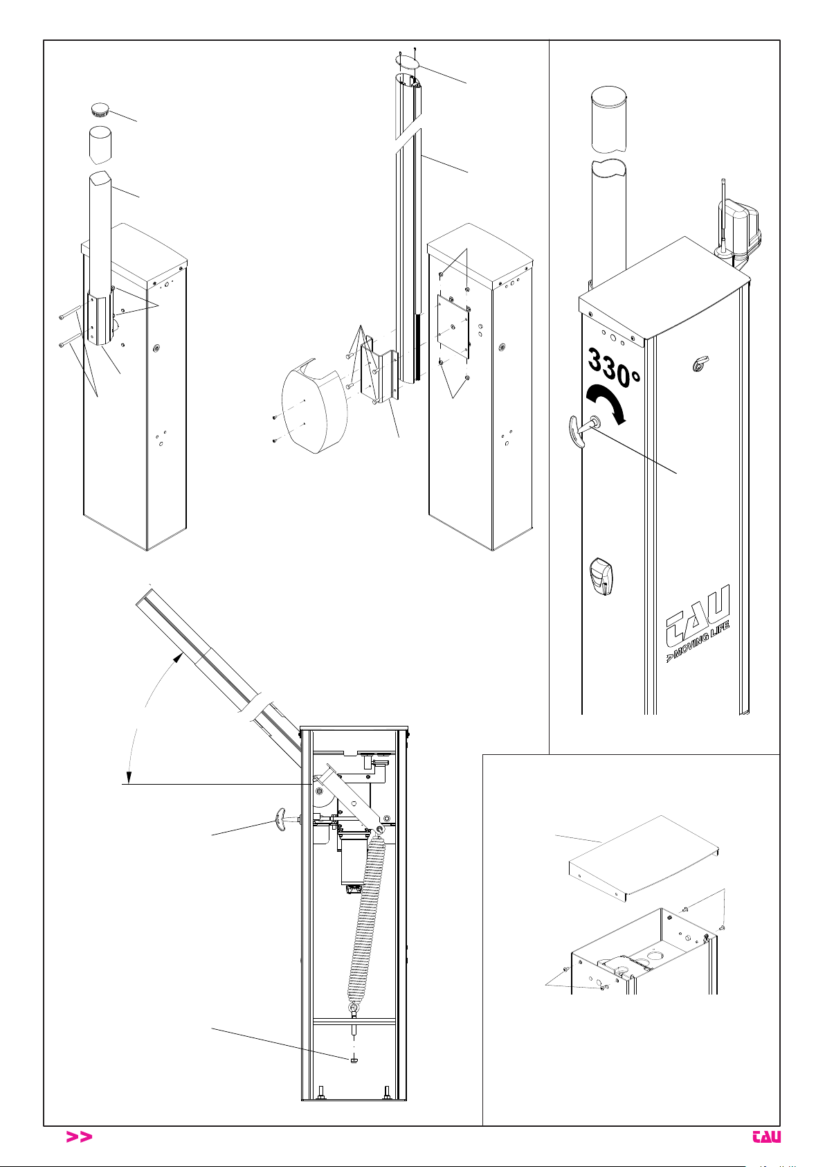
E
A
E
A
D
C
B
D
C
D
B
1
g. 5
18
45°
A
1
2
B
g. 6
RBL Series Disegni - Drawings - Zeichnen - Projets - Dibujos - Desenhos
RBLO Series
g. 7
2
RBLO-E
RBLO
g. 8
Page 25

1
2
1
2
1
g. 9
g. 10
2
2
1
1
g. 12
3
d
e
7 4
6
c
f
5
b
2
g. 11
RBL Series Disegni - Drawings - Zeichnen - Projets - Dibujos - Desenhos
RBLO Series
4
a
230 VAC
1
19
- - -- - - - - - - - - - - - - - - - - - - - - - - - - - - - - - - - - - - - - - - - - - - - - - - - - - - - - - - - - - - - - - - - - - - - - - - - - - - - - - - - - - - - - - - - - - - - - -
Page 26

Data
Date
Datum
Date
Fecha
Descrizione intervento
Description of job
Beschreibung des Eingriffs
Description intervention
Descripción del trabajo
Descrição da intervenção
Parti sostituite
Parts replaced
Ersetzte teile
Parties remplacées
Piezas sustituidas
Componentes
substituídos
Firma manutentore
Fitter’s signature
Unterschrift des
Wartungsmannes
Signature réparateur
Firma del técnico
Assinatura do Técnico
Firma utilizzatore
User’s signature
Unterschrift des
Benutzers
Signature utilisateur
Firma del usuario
Assinatura do Utilizador
RBLO Series
7
Page 27

Data
Date
Datum
Date
Fecha
Descrizione intervento
Description of job
Beschreibung des Eingriffs
Description intervention
Descripción del trabajo
Descrição da intervenção
Parti sostituite
Parts replaced
Ersetzte teile
Parties remplacées
Piezas sustituidas
Componentes
substituídos
Firma manutentore
Fitter’s signature
Unterschrift des
Wartungsmannes
Signature réparateur
Firma del técnico
Assinatura do Técnico
Firma utilizzatore
User’s signature
Unterschrift des
Benutzers
Signature utilisateur
Firma del usuario
Assinatura do Utilizador
RBLO Series
7
Page 28

ALLGEMEINE HINWEISE
1_ Falls in den Anweisungen der elektronischen Steuerung nicht
vorgesehen, ist zu prüfen, ob vor der elektrischen Anlage ein
geeigneter Differentialschalter sowie ein Überstromschutz (allpoliger magnetothermischer Schalter C6 mit mindestens 3 mm
Öffnung der Kontakte) mit Konformitätsmarke mit den internationalen Vorschriften vorhanden sind. Diese Vorrichtung muss
vor einer zufälligen Aktivierung geschützt sein (indem sie z.B.
in einen Schaltschrank mit Schloss und Schlüssel eingebaut
wird).
2_ Anordnung eines eventuellen Fotozellenpaars: der Aktions-
kreis der Fotozellen muss sich auf einer Höhe von 50 ÷ 60 cm
ab Boden und in einem Abstand von der Bewegungsebene
des Schrankenbaums nicht über 15 cm benden. Nach der
Installation muss gemäß EN 12445 der korrekte Betrieb der
Fotozellen überprüft werden.
BITTE BEMERKEN: Die Anlage muss korrekt geerdet werden.
Die Angaben in den vorliegenden Anweisungen dienen nur als
Hinweis; die Firma TAU Srl behält sich das Recht vor, sie jederzeit
zu ändern.
Die Anlage in Übereinstimmung mit den im jeweiligen Land
gültigen Vorschriften und Gesetzen ausführen.
DEUTSCH
INSTALLATIONSHINWEISE
• Diese Anweisungen wenden sich ausschließlich an qualiziertes Personal, das die Konstruktionskriterien und die Unfallschutzvorrichtungen für motorbetriebene Türen und Tore kennt
(die gültigen Vorschriften und Gesetze einhalten).
• Gemäß Vorschrift EN12635 hat der Installateur dem Endbenutzer eine Anleitung zu übergeben.
• Vor der Installation hat der Installateur die Risikoanalyse der
automatisierten Schließvorrichtung sowie die Sicherung der
ermittelten Gefahrenbereiche auszuführen (gemäß EN 12453
und EN 12445).
• Die verschiedenen elektrischen Bestandteile außerhalb des
Antriebs (wie z.B. Fotozellen, Blinkleuchten, usw.) müssen gemäß EN 60204-1 und den laut EN 12453 angebrachten Änderungen verdrahtet sein.
• Eine eventuelle Tastatur zur manuellen Bewegung muss so angebracht sein, dass sich jener, der die Tastatur betätigt, nicht in
einem Gefahrenbereich bendet; weiterhin muss eine zufällige
Betätigung der Tasten möglichst vermieden werden.
• Die Schaltvorrichtungen des Automatismus (Tastatur, Fernbedienung, usw.) außerhalb der Reichweite von Kindern halten.
Die Schaltvorrichtungen müssen sich in einer Höhe von mindestens 1,5 m ab Boden und außerhalb des Aktionskreises der
beweglichen Teile benden.
• Vor Arbeiten an der Anlage wie Installation, Einstellung oder
Wartung muss die Spannung durch Betätigung des magnetothermischen Schalters vor derselben abgeschaltet werden.
Die FIRMA TAU ÜBERNIMMT KEINERLEI HAFTUNG für eventuelle Schäden infolge der Nichtbeachtung der Sicherheitsvorschriften und der gültigen Gesetze bei der Installation.
GESAMTABMESSUNGEN
In Abb. 1 sind die wichtigsten Gesamtabmessungen der Schranke
angegeben, in Abb. 2 die Abmessungen der Fundamentgegenplat-
te.
ANORDNUNG DER SCHRANKE
Neben dem korrekten Betrieb der Schranke sind auch folgende
Kriterien zu berücksichtigen:
1_ vor der Installation des Schrankenbaums ist zu prüfen, dass
der gesamte Raum darüber ohne Hindernisse (Terrassen, Kabel, Bäume usw.) ist
2_ gute Sicht aus ausreichender Entfernung, um Aufprall zu ver-
meiden (z.B. Hecken usw. beachten)
3_ der Boden muss eine stabile Anordnung der Schranke gewähr-
leisten
4_ es dürfen keine Rohrleitungen und/oder elektrische Leitungen
vorhanden sein, die bei der Vorbereitung des Installationsorts
beschädigt werden können
5_ die Länge der elektrischen Leitungen, mit denen die Schranke
operativ gemacht wird, muss so kurz wie möglich sein
6_ Anordnung unter Beachtung der diesbezüglich gültigen natio-
nalen Vorschriften.
VORBEREITUNG DES INSTALLATIONSORTES
Eine rechteckige Fundamentplatte (A, Abb. 3) mit geeigneten Abmessungen erstellen und die Bohrungen für die Kabel vorbereiten.
Möglichst die Fundamentgegenplatte (B, Abb. 3) mit den 4 mitgelieferten Zugstangen verwenden, die in der Fundamentplatte zu
versenken sind, oder den Schrank der Schranke mit 4 Ankerdübeln M10x120 (C, Abb. 3) direkt auf der fertigen Fundamentplatte
befestigen. Die Stärke der Fundamentplatte muss mindestens 10
cm sein; falls es der Zustand des Bodens erfordert, kann sie auch
stärker sein.
VERANKERUNG DER SCHRANKE
Die Schranke ohne Schrankenbaum muss nun positioniert und mit
dem Boden verankert werden, indem die Muttern an den Zugstangen fest angezogen werden (oder mit den Ankerdübeln). Nun die
unbedingte Stabilität der Verankerung überprüfen; ggf. dementsprechend vorgehen.
EINSTELLUNG DER BEWEGUNGSRICHTUNG DER
SCHRANKE
Mit Schranke rechts (RE) ist der auf der rechten Seite angeordnete
Schrank (Ansicht vom Inneren der Einfahrt) gemeint (die Schranktür ist üblicherweise nach innen gerichtet).
1_ Die Schranke kann nach rechts (RE) funktionieren, wenn die
Platten wie in A - Abb. 4 montiert ist.
Mit Schranke links (LI) ist der auf der linken Seite angeordnete
Schrank (Ansicht vom Inneren der Einfahrt) gemeint (die Schranktür ist üblicherweise nach innen gerichtet).
2_ Die Schranke kann nach links (LI) funktionieren, wenn die Plat-
ten wie in D - Abb. 4 montiert ist.
Gewöhnlich wird „RBLO“ mit Schrank RECHTS (RE) geliefert.
Falls die Schranke in die Gestaltung LINKS (LI) umgebaut werden
muss, und wie folgt vorgehen:
1_ nachdem Muttern und Unterlegscheiben entfernt worden sind,
die obere Halterung (B, Abb. 4) abmontieren, um 180° drehen
und erneut befestigen;
RBLO-E: Entfernen Sie die Endanschläge und befestigen Sie
sie an der der Halterung gegenüberliegenden Seite (1 B Abb.
4);
2_ Entfernen Sie nun die mechanische Sperre (1 C Abb. 4) mit
der entsprechenden Mutter und befestigen Sie sie auf der dem
Schrank gegenüberliegenden Seite (2 C Abb. 4);
3_ Nach der Änderung der Bewegungsrichtung der Schran-
ke müssen die Motoranschlüsse umgekehrt werden (siehe
Anweisungen K205M für RBLO, Anweisungen K101M für
RBLO-E).
BITTE BEMERKEN: Nach der Änderung der Bewegun-gsrichtung ist die Anordnung der Vorrichtungen umgekehrt.
BEFESTIGUNG UND AUSWUCHTEN DES SCHRANKENBAUMS
Das korrekte Auswuchten ist für den korrekten Betrieb der Schranke sehr wichtig.
Dieser Vorgang wird erst nach der endgültigen Montage des
Schrankenbaums und aller eventuellen Zubehörteile ausgeführt.
Alle Arbeiten müssen ohne Stromversorgung und mit entriegelter Schranke ausgeführt werden (siehe Kap. „Manuelle Entriegelung“).
Abb. 5: die mit den mitgelieferten Kappen (E) schließen; den
Schrankenbaum (A) in den Schrankenbaumhalter (B)
stecken und mit den 2/4 Schrauben (C) und den Muttern (D) befestigen;
Hinweis: Die Stange muss über die gesamte Länge der
Stangenhalterung eingeführt werden.
Abb. 6: die manuelle Entriegelung (A) betätigen; einen Sicher-
heitsabstand halten. Der Schrankenbaum muss von allein auf 45° gehen, andernfalls die Federspannung (B)
mit Hilfe der Stellmutter betätigen (19er Inbusschlüssel). Den Schrankenbaum senken und loslassen. Prüfen, dass er auf 45° steht.
BITTE BEMERKEN: sollte beim Auswuchten eine höhere/senken Last als vorgesehen notwendig sein, muss die Öse (1 D,
Abb. 4) im Loch nach rechts oder links verschoben werden,
um die Last zu erhöhen bzw. zu verringern.
20
RBLO Series
Page 29

MANUELLE ENTRIEGELUNG
1_ den mitgelieferten Entriegelungshebel (1, Abb. 7) einstecken;
2_ den Schlüssel um ca. 330° im Uhrzeigersinn drehen (bei an-
fänglichem Widerstand kräftiger drehen, man verursacht keine
Schäden).
Den Entriegelungsschlüssel vor der manuellen Betätigung
des Schrankenbaums immer bis zum Anschlag drehen.
Nach erfolgter Entriegelung muss der Schrankenbaum automatisch im Gleichgewicht (ca. 45°) sein.
ANSCHLUSS DER VERSORGUNG UND EXTERNE
SCHALT- UND SICHERHEITSVORRICHTUNGEN
Jede Vorrichtung inklusive Stromversorgung muss fachgerecht
und nach den gültigen Vorschriften installiert sein. Die Leistungskabel vor allem im Fall von langen Strecken (über 50 m) von den
Steuerkabeln trennen. Was den Kabelquerschnitt (Antenne ausgeschlossen) betrifft, empehlt die Firma TAU: Versorgung 1,5 mm²,
sonstige Kabel 0,5 mm²; die Norm IEC 364 sowie die im jeweiligen
Land gültigen Installationsvorschriften einhalten. Für den Zugriff
auf die Steuerkarten, den Schrankdeckel (1, Abb. 8) nach Entfernung der Sperrschrauben (2, Abb. 8)abnehmen.
BITTE BEMERKEN: Die Verdrahtungen innen sind bereits
ausgeführt und getestet. Anzuschließen sind die Versorgung,
die externe Fotozelle, eventuelle Fernsteuerungen. Die Steuerkarte muss programmiert werden.
WICHTIG
1_ Besonders hingewiesen wird auf eine wirksame Erdung unter
Einhaltung der gültigen Vorschriften, da für die Sicherheit des
Geräts sehr wichtig ist. Der Hersteller übernimmt keinerlei Haftung für Schäden infolge der Nichtbeachtung dieser Vorschrift.
2_ Zur Überwachung der Versorgung wird die Montage eines ma-
gnetothermischen Schalters vor der Schranke empfohlen, falls
diese aus Sicherheitsgründen entfernt werden muss.
EINSTELLUNG DER ELEKTRISCHEN ENDANSCHLÄGE
(RBLO-E)
Die elektrischen Endanschläge, die auf dem RBLO-E montiert sind,
werden zur Einstellung des Beginns der Verlangsamungsphase beim Öffnen und Schließen verwendet. Um die Nocken der
Endanschläge einzustellen (1 Abb. 9), müssen diese auf den Ring,
in dem sie untergebracht sind, laufen gelassen werden (2 Abb. 9),
bis der optimale Lauf der Stange erreicht ist.
Diese Einstellung steht in engem Zusammenhang mit den logischen Einstellungen der Steuerkarte. Wenn die Stange beispielsweise unmittelbar nach der Betätigung des Mikroschalters anhält,
muss auch das Drehmoment des Motors erhöht werden (siehe
Abschnitt „Logische Einstellungen“ in der Gebrauchsanweisung
der Steuerkarte K101M). Sobald der Vorgang (des Öffnens oder
Schließens) abgeschlossen ist, läuft der Motor hingegen noch ein
paar Sekunden lang. In diesem Fall muss die Messschwelle der
Endanschläge erhöht werden (siehe Abschnitt „Logische Einstellungen“ in der Gebrauchsanweisung der Steuerkarte K101M).
EINSTELLUNG DER MECHANISCHEN ENDANSCHLÄGE
Gewöhnlich wird die Schranke für eine optimale Bewegung des
Schrankenbaums mit bereits eingestellten mechanischen Endanschläge geliefert.
Falls die Fundamentplatte nicht korrekt nivelliert ist, könnte der
Schrankenbaum nicht einwandfrei horizontal oder vertikal sein, mit
negativer Wirkung auf das Aussehen der Anlage.
Um dies zu beheben, kann der Hub des Schrankenbaums geändert werden, indem die schwingungsdämpfenden Stopfen des
mechanischen Endanschlags (1, Abb. 10) durch Betätigung ihrer
Feststellgegenmuttern (2, Abb. 10) nach vorne oder hinten verschoben werden.
BITTE BEMERKEN: nach jeder Positionsänderung der mechanischen Endanschläge muss das Speicherverfahren an der
Steuerkarte wiederholt werden (siehe Anweisungen K205M).
Die Stromversorgung nach der Einstellung wieder herstellen
und das Speicherverfahren an der Steuerkarte ausführen (siehe Anweisungen K205M); die korrekte Position ab der zweiten
automatischen Bewegung überprüfen (bei der ersten Bewegung wird die Steuerung die neuen Endschalter erfassen) und
das Verfahren ggf. wiederholen.
ABSCHLIEßENDE ARBEITEN
Die Wirksamkeit jeder Steuer- oder Kontrollvorrichtung der Schran-
RBLO Series
ke überprüfen; den korrekten Betrieb derselben überprüfen, bevor
sie dem Endbenutzer übergeben wird.
Dann die Schilder, die auf das Vorhandensein der automatischen
Schranke hinweisen, gut sichtbar anbringen.
BEDIENUNG
Der Einsatzzweck der Schranke ist ausschließlich, den Zugang von
Fahrzeugen und/oder Personen in durch den Schrankenbaum geschützte Bereiche zu begrenzen. Für Stromausfall kann die Schranke
auf Anfrage mit Batterieversorgung (12V Batterie für ca. 100 Bewegungen) geliefert werden (RBLO).
Weiterhin wird darauf hingewiesen, dass es sich um ein Elektrogerät handelt, das als solches vorsichtig und achtsam behandelt und
benutzt werden muss. Insbesondere:
• das Gerät nicht mit nassen Händen und/oder nassen Füßen
bzw. barfuss berühren;
• die Schranke im Fall bereits festgestellter oder ungewisser
Betriebsstörungen nicht im automatischen oder halbautomati-
schen Modus betreiben;
• nicht am Stromkabel ziehen, um das Gerät abzutrennen;
• Kindern oder Unfähigen die Schlüssel des Schranks und die
Schaltvorrichtungen (auch Funksteuerung) keinesfalls überlas-
sen;
• die Schranke nur bewegen, wenn sie bestens sichtbar ist;
• den Aktionskreis der Schranke nicht betreten, solange sie sich
bewegt. Warten, bis sie steht.
• sich keinesfalls auf den Schrank oder den Schrankenbaum
stützen, auch nicht, wenn die Schranke nicht aktiviert ist. Nicht
im Aktionskreis der Schranke verweilen;
• Kinder oder Tiere nicht in Schrankennähe spielen lassen;
• die Schranke nicht für andere Zwecke als vorgesehen benut-
zen (z.B. Heben von Gewichten oder Personen); Der Hersteller
übernimmt keinerlei Haftung für Schäden aufgrund eines sol-
chen Verhaltens;
• die Schranke regelmäßig durch Fachpersonal warten lassen;
• Bei Störungen die Versorgung abschalten. Die Schranke nur,
wenn sicher, von Hand betätigen. Keine Eingriffe ausführen
und ausschließlich qualiziertes Personal der Herstellerrma
oder autorisiertes Personal zu Rate ziehen. Um die Sicherheit
der Schranke nicht zu beeinträchtigen, immer prüfen, dass Ori-
ginalersatzteile benutzt werden.
TYPISCHE ANLAGE (Abb. 11)
1_ Getriebemotor
2_ Standsäule für Fotozellen
3_ Blinkleuchte mit Antenne
4_ Sicherheitsfotozellen
5_ Magnetmassedetektor
6_ Schrankenbaum (max. Länge 4 m)
7_ Stützgabel für Schrankenbaum
Kabelquerschnitt:
a 3 x 1,5 mm²
b 2 x 0,5 mm²
c 4 x 0,5 mm²
d 2 x 0,5 mm²
e RG58
f 4 x 0,5 mm²
WARTUNG
Darf nur durch Fachpersonal nach Abschaltung der Stromver-sorgung zum Motor ausgeführt werden.
Alle 100.000 Bewegungen folgendes überprüfen:
- Einfettung der Feder.
- Gleichgewicht des Schrankenbaums (siehe Kap. „BEFESTI-
GUNG UND AUSWUCHTEN DES SCHRANKEN-BAUMS“);
- Wirksamkeit der Kraftbegrenzung;
- Zustand der Batterie;
- Wirksamkeit der Schutz- und Sicherheitsvorrichtungen;
- Abnützung der mechanischen Endanschläge und Endschal-
tereinstellung (siehe Kap. „EINSTELLUNG DER ENDSCHAL-
TER“).
Die oben beschriebene Wartung ist für die Lebensdauer und
den korrekten Betrieb des Produktes sehr wichtig.
Allgemeines
Die Schranke darf in dieser Phase nicht durch Dritte aktiviert wer-
21
DEUTSCH
Page 30

den, daher die Netzstromversorgung (und die Batterie, falls vorhanden) abtrennen.
• Um die Wartung zu erleichtern, den Schrankenbaum vorher
entriegeln.
häugsten Störungen kurz behandelt, so dass die Schranke wieder in Betrieb gesetzt werden kann.
Es handelt sich hier nicht um eine komplette Liste (sowohl was die
Ursachen als auch die Störungen betrifft).
Einfetten
1_ Die Schranktür öffnen;
2_ die Ösen der Ausgleichsfeder einfetten (1, Abb. 12);
3_ die Stelle einfetten, an der sich der Nocken der manuellen Ent-
riegelung und der Entriegelungshebel berühren (2, Abb. 12).
4_ Abstand halten von Zahnrädern oder mechanischen Teilen, die
sich bewegen können.
HÄUFIGKEIT: alle 100.000 Bewegungen oder alle 6 Monate,
andernfalls wird die Garantie ungültig.
Gleichgewicht des Schrankenbaums
Das Gleichgewicht des Schrankenbaums überprüfen und die in
Kap. „Befestigung und Auswuchten des Schrankenbaums“ beschriebenen Vorgänge wiederholen. Dieser Vorgang ist für den
korrekten Betrieb und die Lebensdauer der Schranke sehr wichtig.
Ggf. die Federspannung erhöhen, um ihre Abnützung auszugleichen. Für den Ersatz der Feder wird auf das nachfolgende Kap.
DEUTSCH
„Außergewöhnliche Wartung und Reparaturen“ verwiesen.
HÄUFIGKEIT: alle 100.000 Bewegungen oder alle 6 Monate, an-
dernfalls wird die Garantie ungültig.
Kontrolle der Wirksamkeit der Kraftbegrenzung;
Prüfen, dass das effektive Verhalten der Schranke mit dem bei der
Installation bestimmten übereinstimmt.
HÄUFIGKEIT: alle 100.000 Bewegungen oder alle 6 Monate, an-
dernfalls wird die Garantie ungültig.
Überprüfung der 12Vcc Batterie
Die Batterieladung mit einem Multimeter überprüfen. Eine nicht
mehr verwendbare Batterie mit einer Originalbatterie ersetzen. Die
alte Batterie nicht in die Umwelt geben.
HÄUFIGKEIT: alle 100.000 Bewegungen oder alle 6 Monate, an-
dernfalls wird die Garantie ungültig.
Überprüfung der restlichen Schutz- und Sicherheitsvorrichtungen
Fotozellen: sie können sowohl in Öffnung als auch in Schließung
aktiviert sein; prüfen, wie die Dip-Switches programmiert sind. Das
Außengehäuse reinigen.
Prüfen, ob folgendes zutrifft:
• Blinkleuchte funktioniert und ist gut sichtbar
• Gefahrschild an der Tür gut angebracht und sichtbar
• Gefahrschild am Teil hinter der Schranke gut angebracht und
sichtbar. Andernfalls den ursprünglichen Sicherheitsgrad wieder herstellen oder ersetzen.
HÄUFIGKEIT: alle 6 Monate, andernfalls wird die Garantie
ungültig.
AUßERGEWÖHNLICHE WARTUNG UND REPARATUREN
BITTE BEMERKEN: NACH DEN ERSTEN 2000 BEWEGUNGEN
MUSS EIN NEUES AUSGLEICHSVERFAHREN DES SCHRANKENBAUMS AUSGEFÜHRT WERDEN.
Falls schwierigere Reparaturen oder der Ersatz elektromechanischer Elemente notwendig sind, muss der Block, an dem die Arbeit
ausgeführt werden muss (Steuerkarte, Getriebemotorblock), ganz
entfernt werden, so dass die Reparatur in der Werkstatt der Herstellerrma oder durch autorisierte Techniker ausgeführt werden
kann. Andernfalls können die Sicherheit und Zuverlässigkeit der
Schranke beeinträchtigt werden (ggf. mit Ungültigkeit der Garantie).
BITTE BEMERKEN: Falls die Schranke in salzhaltiger oder
korrosiver Umgebung benutzt wird, muss die Wartung je nach
Umgebungsbedingungen häuger ausgeführt werden; in
diesem Fall wird auch eine Überprüfung des äußeren Metallschranks empfohlen.
a_ Schranke blockiert (geöffnet, geschlossen oder halb geöffnet):
1_ keine Versorgung;
2_ Schaltvorrichtungen nicht efzient;
3_ Sicherung durchgebrannt;
4_ Fotozellen (auch in Öffnung befähigt) aktiviert, da nicht ge-
uchtet und/oder weil ein Hindernis vorhanden ist (Gras, usw.);
b_ Schranke öffnet und schließt sich ständig;
1_ falsche Kontakte der Tasten der Fernbedienungen und der
Schlüsseltaster, die eingeschaltet bleiben, kontrollieren;
c_ Schranke bleibt geöffnet;
1_ Fotozellen aktiviert, da nicht geuchtet und/oder schmutzig
(Schlamm, usw.) und/oder weil ein Hindernis vorhanden ist
(Gras, usw.);
d_ Schranke öffnet sich nur schwer;
1_ Schrankenbaumausgleichsfeder nicht korrekt gespannt;
e_ Schranke hebt/senkt sich mehr als vorgesehen;
1_ der mechanischen Endanschläge müssen eingestellt werden
(siehe Kap. „EINSTELLUNG DER ENDSCHALTER“).
ABBRUCH
Am Ende ihrer Lebensdauer muss die Schranke entfernt werden;
wieder verwendbare Stoffe sind zu recyclen. Die örtlichen und/
oder nationalen Verordnungen und Gesetze beachten. Folgende
Bestandteile können recycled werden:
• mit Epoxydlack angestrichener Schrank
• Gehäuse der Blinkleuchte aus Metacrylat
• Abteil der Steuerkarte aus Polycarbonat
• elektronische Karten
• 12V DC Trockenbatterie (Bleisäure)
• Lithiumfett im Getriebemotor
• Verbindungen und kleinere Schutzvorrichtungen aus Gummi
und/oder Plastik.
DIE UMWELT SCHÜTZEN!
HINWEISE ZUR DEMONTAGE: Die Demontage der Schranke
muss gemäß folgender Sicherheitsvorschriften ausgeführt werden: die Schranke als erstes vom Stromnetz abtrennen. Die Stellmutter der Ausgleichsfeder lösen (nicht ganz ausdrehen), damit
der Schrankenbaum bequemer entfernt werden kann. Dann die
Ankerschrauben des Schranks ausdrehen, damit dieser beliebig
verschoben werden kann.
TRANSPORT
Schranke und Schrankenbaum werden in getrennten Kartons geliefert, da der Schrankenbaum auch auf Anfrage gekauft werden
kann.
Bei Verschiebungen immer achtsam und fachkundig vorgehen.
Zum Heben oder Verschieben werden hand- oder motorbetriebene Wagen empfohlen. Die Lagerung, wenn auch nur vorübergehend, muss vertikal in der auf der Packung angegebenen Richtung
erfolgen. Berücksichtigen, dass der hohe Schwerpunkt Unstabilität
verursacht.
Bei der Lagerung des Schrankenbaums ist auf Vorsprünge oder
Lasten zu achten, die ihn beschädigen können. Nachdem die Verpackung entfernt ist, muss das Produkt auf Schäden überprüft
werden. Verpackungen nicht in die Umwelt geben, sondern nach
den im Benutzungsland gültigen Vorschriften recyclen.
ACHTUNG: Kindern kein Verpackungsmaterial handhaben
lassen, um Erstickungen oder sonstige Gefahren zu vermeiden.
DIAGNOSE DER HÄUFIGSTEN STÖRUNGSURSACHEN
In diesem Abschnitt werden die wahrscheinlichsten Ursachen der
22
RBLO Series
GARANTIE: ALLGEMEINE BEDINGUGEN
Die Garantie der Firma TAU hat 24 Monate Gültigkeit ab Kaufda-
Page 31

tum (das Datum muss durch eine Quittung oder Rechnung belegt
sein).
Die Garantie schließt die Reparatur mit kostenlosem Ersatz (ab
Werk der Firma TAU: Verpackungs- und Transportkosten gehen
zu Lasten des Kunden) jener Teile ein, die von TAU anerkannte
Fabrikations- oder Materialfehler aufweisen.
Im Falle von Eingriffen am Standort des Kunden, auch in der Garantiezeit, hat der Kunde ein “feste Abrufgebühr” für die Reisekosten zum Standort des Kunden und die Arbeitskraft zu zahlen.
Die Garantie wird in folgenden Fällen ungültig:
• wenn der Defekt durch eine Installation verursacht ist, die
nicht nach den in jeder Packung enthaltenen Herstelleranweisungen erfolgte.
• wenn für die Installation der Vorrichtung auch andere Teile
als Original-TAU-Komponenten verwendet wurden.
• wenn die Schäden durch Naturkatastrophen, Handhabungen, Spannungsüberlasten, unkorrekte Versorgung, unsachgemäße Reparaturen, falsche Installation oder sonstiges, für das die Firma TAU keine Verantwortung hat, verursacht sind.
• wenn die regelmäßigen Wartungsarbeiten nicht durch einen Fachtechniker nach den in jeder Packung enthaltenen
Herstelleranweisungen ausgeführt worden sind.
• Verschleiß den Komponenten.
Reparatur oder Ersatz von Teilen während der Garantiezeit führt
zu keiner Verlängerung derselben.
Bei industrieller, beruicher oder ähnlicher Nutzung hat diese Garantie eine Gültigkeit von 12 Monaten.
DEUTSCH
RBLO Series
23
Page 32

INTEGRIERUNGSERKLÄRUNG DES HERSTELLERS
(gemäß der Europäischen Richtlinie 2006/42/EG Anl. II.B)
Hersteller: TAU S.r.l.
Adresse: Via E. Fermi, 43
36066 Sandrigo (Vi)
ITA LY
Erklärt unter seiner Haftung, dass das Produkt: Elektromechanischer Antrieb
für die automatische Bewegung von: Schranken
für eine Anwendung: Allgemein
Einschließlich: Elektronische Steuerung
DEUTSCH
Modell: RBLO
Typ: RBLO / RBLO-I / RBLO-R / RBLO-E
Seriennummer: SIEHE SILBERETIKETTE
Handelsbezeichnung: AUTOMATISCHE SCHRANKE
ausgeführt wurde, um in einen Verschluss integriert zu werden (Automatische Schranke) oder um mit anderen Vorrichtungen kombiniert
zu werden, um diesen Verschluss zu bewegen, und somit gemäß der Maschinenrichtlinie 2006/42/EG eine Maschine darstellt.
Außerdem erklärt er, dass dieses Produkt den grundsätzlichen Sicherheitseigenschaften der folgenden Richtlinien EWG entspricht:
- 2014/35/EU Niederspannungsrichtlinie
- 2014/30/EU Richtlinie für elektromagnetische Kompatibilität
Und wo gefordert, der Richtlinie:
- 2014/53/EU Radio equipment and telecommunications terminal equipment
Außerdem wird erklärt, dass es nicht zugelassen ist, die Vorrichtung in Betrieb zu setzen, bis die Maschine, in die sie integriert wird
oder deren Bestandteil sie sein wird, identiziert und die Konformität gegenüber dem Inhalt der Richtlinie 2006/42/EG erklärt wurde.
Die folgenden Normen und technische Verzeichnisse wurden angewandt:
EN 61000-6-2; EN 61000-6-3; EN 60335-1; ETSI EN 301 489-1 V1.9.2; ETSI EN 301 489-3 V1.6.1;
EN 300 220-2 V2.4.1; EN 12453:2000; EN 12445:2000; EN 60335-2-103.
Er verpichtet sich, auf ausdrücklichen Wunsch der nationalen Behörden, Informationen über die Fastmaschinen zu übersenden.
Sandrigo, 24/01/2018
Der gesetzliche Vertreter
_________________________________________
Loris Virgilio Danieli
Name und Adresse der beauftragten Person zur Vorlegung der zugehörigen technischen Unterlagen:
Loris Virgilio Danieli - via E. Fermi, 43 - 3606 Sandrigo (Vi) Italia
24
RBLO Series
Page 33

RECOMMANDATIONS DE CARACTÈRE GÉNÉRAL
1_ Si ça n’est pas prévu dans les instructions de la logique élec-
tronique de commande, vérier qu’il y a bien, en amont de l’installation électrique, un interrupteur différentiel et une protection
contre la surcharge adéquats (interrupteur magnétothermique
C6 omnipolaire avec ouverture minimum des contacts égale à
3 mm) avec marque de conformité aux normes internationales.
Ce dispositif doit être protégé contre la refermeture accidentelle (par ex. en l’installant dans une armoire fermée à clé).
2_ Positionnement d’une éventuelle paire de photocellules : le
rayon des photocellules doit se trouver à une hauteur de 50 ÷
60 cm par rapport au sol et à une distance du plan de mouvement de la lisse ne dépassant pas 15 cm. Leur fonctionnement correct doit être vérié à la n de l’installation conformément à la norme EN 12445.
Note: la mise à la terre de l’installation est obligatoire !
Les données gurant dans ces instructions sont purement indicatives ; TAU Srl se réserve le droit de les modier à tout moment.
Réaliser l’installation conformément aux normes et lois en
vigueur dans le pays de destination.
AVERTISSEMENTS POUR L’INSTALLATION
• Ce livret d’instructions s’adresse exclusivement à du personnel
qualié connaissant les critères de construction et les disposi-
tifs de protection contre les accidents pour les portails et portes
motorisés (respecter les normes et lois en vigueur).
• L’installateur devra délivrer à l’utilisateur nal un livret d’instructions conforme à la norme EN12635.
• L’installateur, avant de procéder à l’installation, doit prévoir
l’analyse des risques de la fermeture automatisée nale et la
mise en sécurité des points dangereux identiés (suivant Ies
normes EN 12453 et EN 12445).
• Le câblage des différents composants électriques extérieurs à
l’opérateur (par exemple photocellules, clignotants, etc.) doit
être effectué suivant la norme EN 60204-1 et les modications
apportées à celle-ci par la norme EN 12453.
• L’éventuelle installation d’un clavier pour la commande manuelle du mouvement doit être faite en positionnant celui-ci de
manière que la personne qui l’actionne ne se trouve pas dans
une position dangereuse ; de plus, il faudra faire en sorte de
réduire le risque d’actionnement accidentel des touches de
commande.
• Conservez les commandes de l’automatisme (clavier de commande, télécommande, etc.) hors de portée des enfants. Les
commandes doivent être situées à 1,5 m de hauteur minimum
par rapport au sol et en dehors du rayon d’action des parties
mobiles.
• Avant toute opération d’installation, de réglage ou de maintenance de l’installation, couper la tension en agissant sur l’interrupteur magnétothermique situé en amont.
LA SOCIÉTÉ TAU DÉCLINE TOUTE RESPONSABILITÉ pour les
éventuels dommages provoqués par la non-observation, lors de
l’installation, des normes de sécurité et des lois en vigueur.
MESURES D’ENCOMBREMENT
La g. 1 indique les principales dimensions d’encombrement de la
barrière ; la g. 2 indique les dimensions de la contre-plaque de
fondation.
OÙ PLACER LA BARRIÈRE
En plus du critère fonctionnel, respecter également les critères
suivants :
1_ avant d’installer la lisse, faire bien attention que tout l’espace
situé au-dessus soit sans obstacles (terrasses, câbles tendus,
arbres, etc.)
2_ bonne visibilité à des distances sufsantes pour éviter l’impact
(attention aux haies, etc.)
3_ sol adapté pour garantir un positionnement stable de la bar-
rière
4_ absence de canalisations et/ou conduites électriques risquant
d’être endommagées dans la phase de préparation du site
5_ les conduites électriques nécessaires pour le bon fonctionne-
ment de la barrière doivent être les plus courtes possible
6_ positionnement respectueux des normes nationales en vigueur
en la matière.
PRÉPARATION DU SITE
Créer une dalle en béton (A g. 3) de forme rectangulaire et de
dimensions adéquates en prévoyant les trous pour la sortie des
câbles. Utiliser si possible la contre-plaque de fondation (B g. 3),
avec les 4 boulons fournis à sceller dans le béton de la dalle ; une
fois la dalle réalisée, xer l’armoire de la barrière directement avec
4 chevilles d’ancrage M10x120 (C g. 3). L’épaisseur de la dalle
doit être d’au moins 10 cm et peut être éventuellement augmentée
si les conditions du terrain l’exigent.
RBLO Series
ANCRAGE BARRIÈRE
La barrière dépourvue de lisse doit être positionnée puis ancrée
sur le fond en serrant à fond les écrous sur les boulons (ou les
chevilles d’ancrage). Contrôler ensuite la stabilité absolue de l’ancrage et si nécessaire, intervenir pour l’obtenir.
RÉGLAGE DU SENS DE LA BARRIÈRE
Le terme « barrière droite » (D) désigne une barrière avec l’armoire positionnée à droite, vue de l’intérieur du passage (généralement la porte donnant accès à l’intérieur de l’armoire se trouve
vers l’intérieur).
1_ La barrière peut fonctionner à droite (D) en montant la plaque
comme dans A g. 4.
Le terme « barrière gauche » (G) désigne une barrière avec l’armoire positionnée à gauche, vue de l’intérieur du passage (généralement la porte donnant accès à l’intérieur de l’armoire se trouve
vers l’intérieur).
2_ La barrière peut fonctionner à gauche (G) en montant la plaque
comme dans E g. 4.
Normalement « RBLO » est livrée dans la version DROITE (D). Si
l’on a besoin de la transformer en barrière GAUCHE (G), opérer
de la façon suivante :
1_ après avoir enlevé les écrous et les rondelles, retirer le support
supérieur (4 C g. 4), le tourner de 180° et le xer de nouveau ;
RBLO-E: enlever les ns de course et les xer sur l’autre côté
du support (1 B g. 4) ;
2_ enlever maintenant la butée mécanique (1 C g. 4) et son
écrou et la xer sur l’emplacement de l’autre côté de l’armoire
(2 C g. 4) ;
3_ Après avoir modié le sens de la barrière il faut inverser les
connexions du moteur (voir instructions K205M pour RBLO,
instructions K101M pour RBLO-E).
Note : Après avoir modié le sens de la barrière, le positionnement des dispositifs est inversé.
FIXATION DE LA LISSE ET ÉQUILIBRAGE
Un équilibrage correct est fondamental pour un bon fonctionnement de la barrière.
Cette opération ne doit être effectuée que lorsque la lisse
est montée de manière dénitive et avec tous les éventuels
accessoires.
Toutes les opérations doivent être effectuées en l’absence de
courant et avec la barrière débloquée (voir chapitre « Déblocage
manuel ») :
g. 5 : boucher l’extrémité avec le bouchon fournie (E) ; xer la
lisse (A) sur le support (B) et la xer en serrant les 2/4
écrous (D) sur les vis (C) ;
Remarque : la tige doit être insérée sur toute la longueur
du porte-tige.
g. 6 : agir sur le déblocage manuel (A) en gardant une distance
de sécurité. La lisse doit se positionner toute seule à 45°,
en cas contraire agir sur la charge du ressort (B) à l’aide de
l’écrou de réglage (clé à six pans de 19). Abaisser la lisse
et la relâcher. Contrôler qu’elle se positionne à 45°.
Note : si au moment de l’équilibrage on a besoin d’une charge
supérieure/inférieure à la charge autorisée, déplacer le piton
à anneau (1 D g. 4) dans le trou à droite ou à gauche pour
augmenter/diminuer la capacité de charge.
DÉBLOCAGE MANUEL
1_ Introduire la clé de déblocage fournie (1 g. 7) ;
2_ tourner la clé de 330° env. dans le sens des aiguilles d’une
montre (si elle semble résister au début, exercer une force plus
grande sur la clé, il n’y a aucun risque de rupture quelconque).
Tourner toujours à fond la clé de déblocage avant de manœuvrer la lisse à la main.
Quand elle a été débloquée, la lisse doit se mettre automatiquement dans la position d’équilibre (45° env.).
BRANCHEMENT AU SECTEUR ET DES SYSTÈMES EXTÉRIEURS DE COMMANDE ET DE SÉCURITÉ
Chaque dispositif, alimentation incluse, doit être installé dans les
règles de l’art et dans tous les cas suivant les normes en vigueur.
Séparer les câbles de puissance des câbles de commande, surtout si les parcours sont longs (plus de 50 m). Pour la section des
câbles (antenne exclue), TAU conseille : alimentation 1,5 mm²,
autres câbles 0,5 mm² et dans tous les cas, respecter la norme
IEC 364 ainsi que les normes d’installation en vigueur dans le pays
de destination. Pour accéder à la carte de commande, enlever
le couvercle de l’armoire (1 g. 8) après avoir enlevé les vis de
blocage (2 g. 8).
Note: les câblages internes sont déjà effectués et testés. Il
faut effectuer le branchement de l’alimentation, de la photo-
25
FRANCAIS
Page 34

cellule extérieure, des éventuelles commandes à distance
puis programmer la carte.
IMPORTANT
1_ Nous rappelons l’importance d’une mise à la terre efcace pour
la sécurité de l’appareil, subordonnée au respect des normes
en vigueur. Le constructeur ne peut pas être tenu pour responsable des éventuels dommages provoqués par le non-respect
de cette consigne.
2_ Il est conseillé d’installer un interrupteur magnétothermique en
amont de la barrière pour contrôler l’alimentation, si pour des
raisons de sécurité, on doit l’interrompre.
REGLAGE FIN DE COURSE ELECTRIQUES (RBLO-E)
Les ns de course électriques sur la RBLO-E sont utilisés pour
régler le début de la phase de ralentissement en ouverture et
en fermeture. Pour régler les cames d’actionnement de n de
course (1 g. 9) il faut les faire glisser sur l’anneau qui les recueille
(2 g. 9) jusqu’à avoir la meilleure course de la tige.
Ce réglage est strictement lié aux réglages logiques de la carte
de commande. Par exemple, si la tige s’arrête tout de suite après
l’actionnement du micro-interrupteur, il faudra augmenter le couple
moteur (voir sect. «Règlements logiques» sur les instructions
de la carte de commande K101M), si une fois que la manœuvre
(d’ouverture ou de fermeture) est terminée le moteur continue de
tourner pendant quelques secondes, il faudra augmenter le seuil
de détection de n de course (voir sect. «Réglages logiques» sur
les instructions de la carte de commande K101M).
RÉGLAGE FIN DE COURSE MÉCANIQUES
Normalement, la barrière est fournie avec les ns de course mécaniques déjà réglés pour permettre le mouvement idéal de la lisse.
En cas de mise de niveau erronée de la plaque de fondation, la
FRANCAIS
tige pourrait ne pas résulter parfaitement horizontale ou verticale
avec pour conséquence un mauvais résultat esthétique de l’ins-
tallation.
Pour y remédier, il est possible de modier la course de la lisse
en déplaçant en avant ou en arrière les bouchons antivibratoires
d’arrêt mécanique (1 g. 10), en agissant sur les contre-écrous de
blocage (2 g. 10) de ces derniers.
Note : à chaque fois que l’on modie la position des ns de
course mécaniques, il faut répéter la procédure de mémorisation dans la logique de commande (voir instructions K205M).
À la n du réglage, rétablir l’alimentation électrique et effectuer la procédure de mémorisation sur la logique de commande (voir instructions K205M), en vériant à partir de la
seconde manœuvre en automatique (la première sert à la
logique de commande pour acquérir les nouveaux ns de
course) la position correcte de la lisse, répéter éventuellement la procédure.
DERNIÈRES OPÉRATIONS
Après avoir testé l’efcacité de chaque dispositif servant à la commande ou au contrôle de la barrière, s’assurer du rétablissement
de l’intégrité de cette dernière avant de la mettre en service.
Placer à un endroit facilement lisible des panneaux indiquant la
présence de la barrière automatique.
UTILISATION
La barrière a été conçue exclusivement pour limiter le passage
de véhicules et/ou personnes dans des accès protégés, grâce au
barrage exercé par la lisse. Pour pallier aux coupures de courant,
l’installation prévoit sur demande le fonctionnement avec batterie à
sec de 12 V (RBLO, autonomie d’environ 100 manœuvres).
Nous rappelons en outre que l’on est en présence d’un appareil
électrique qui exige que l’on prenne un minimum de précautions
tant quand on s’en approche que lors de l’utilisation proprement
dite.
En particulier, nous recommandons de :
• ne pas toucher l’appareil avec les mains mouillées et/ou les
pieds nus ou mouillés ;
• ne pas permettre le fonctionnement automatique ou semi-automatique en présence de problèmes de fonctionnement certains ou présumés ;
• ne pas tirer sur le câble d’alimentation pour débrancher l’appareil ;
• ne pas laisser les enfants ou les personnes inaptes disposer
des clés de l’armoire ou des commandes (y compris des radiocommandes) même seulement pour s’amuser ;
• ne pas commander la barrière quand celle-ci n’est pas complètement visible ;
• ne pas entrer dans le rayon d’action de la barrière quand elle
26
est en mouvement mais en attendre l’arrêt ;
• ne pas s’appuyer contre l’armoire ou la lisse, sous aucun prétexte, même quand la barrière est inactive et dans tous les cas,
ne pas stationner dans le rayon d’action de la barrière;
• ne pas laisser les enfants ou les animaux jouer à proximité de
la barrière ;
• ne pas utiliser la barrière dans des buts différents de celui pour
lequel elle est conçue (par ex. pour soulever des poids ou des
personnes). Le constructeur décline toute responsabilité pour
les dommages dérivant de tels comportements ;
• assurer la maintenance périodique en la conant à du personnel spécialisé ;
• en cas de panne, couper l’arrivée du courant. Procéder à ges-
tion manuelle seulement si elle est sûre. S’abstenir de toute
intervention et s’adresser exclusivement à du personnel qualié de la maison mère ou agréé par celle-ci. S’assurer dans
tous les cas que les pièces de rechange sont originales pour
ne pas compromettre la sécurité de la barrière.
INSTALLATION TYPE (g. 11)
1_ Motoréducteur
2_ Colonnette pour photocellules
3_ Clignotant avec antenne
4_ Photocellules de sécurité
5_ Détecteur de masse magnétique
6_ Lisse (longueur max. 4 m)
7_ Lyre de repos lisse
Section des câbles :
a 3 x 1,5 mm²
b 2 x 0,5 mm²
c 4 x 0,5 mm²
d 2 x 0,5 mm²
e RG58
f 4 x 0,5 mm²
MAINTENANCE
À effectuer exclusivement par du personnel spécialisé après avoir
coupé l’alimentation électrique du moteur.
Toutes les 100 000 manœuvres complètes vérier :
- le graissage du ressort.
- l’équilibrage de la lisse (voir chapitre « FIXATION DE LA LISSE
ET ÉQUILIBRAGE ») ;
- l’efcacité des forces ;
- l’état de la batterie ;
- l’efcacité des dispositifs de protection et de sécurité ;
- I’usure des butées d’arrêt mécanique et le réglage des ns de
course (voir chapitre « RÉGLAGE FINS DE COURSE »).
La maintenance décrite ci-dessus est vitale pour le fonctionnement du produit dans le temps.
Généralités
La barrière ne doit pas pouvoir être commandée par d’autres personnes durant cette phase ; couper par conséquent l’alimentation
de secteur (et la batterie si elle est présente).
• Débloquer d’abord la lisse pour faciliter l’opération
Graissage
1_ Ouvrir la porte de l’armoire ;
2_ graisser les œillets du ressort d’équilibrage (1 g. 12) ;
3_ graisser le point de contact entre l’excentrique du déblocage
manuel et le levier de déblocage (2 g. 12).
4_ Se tenir à l’écart des engrenages ou des parties mécaniques
qui peuvent entrer en mouvement.
FRÉQUENCE : toutes les 100 000 manœuvres ou tous les 6
mois, sous peine de déchéance de la garantie.
Équilibrage lisse
Contrôler l’équilibrage de la lisse en répétant les manœuvres décrites dans la section « Fixation lisse et équilibrage ». Cette opé-
ration est fondamentale pour le fonctionnement correct et la durée
de la barrière. Si nécessaire, augmenter la charge du ressort pour
en compenser l’usure. S’il est nécessaire de remplacer le ressort,
voir plus loin le paragraphe « Maintenance extraordinaire et réparations ».
FRÉQUENCE : toutes les 100 000 manœuvres ou tous les 6 mois,
sous peine de déchéance de la garantie.
Contrôle efcacité dispositif de limitation des forces
Vérier la correspondance entre le comportement réel et le comportement établi en phase d’installation.
RBLO Series
Page 35

FRÉQUENCE : toutes les 100 000 manœuvres ou tous les 6 mois,
sous peine de déchéance de la garantie.
Contrôle de la batterie 12 Vcc
En utilisant le testeur pour les batteries, vérier le degré de charge
de la batterie. En cas de remplacement, remplacer l’unité inutilisable par une neuve, originale, en veillant à ne pas l’abandonner
dans la nature.
FRÉQUENCE : toutes les 100 000 manœuvres ou tous les 6 mois,
sous peine de déchéance de la garantie.
Contrôle des dispositifs de protection et de sécurité restants ;
Photocellules : elles peuvent agir aussi bien en ouverture qu’en
fermeture ; contrôler la programmation du dip switch. Nettoyer le
boîtier.
Vérier que les spécications suivantes soient respectées :
• Le clignotant fonctionne et est bien visible.
• L’autocollant de signalisation de danger présent sur la porte est
bien xé et visible.
• L’autocollant de signalisation de danger présent sur la partie
arrière de la barrière est bien xé et visible. Si ces dispositifs
ne correspondent pas aux critères ci-dessus, rétablir leur bon
fonctionnement ou si ce n’est pas possible, les remplacer.
FRÉQUENCE : tous les 6 mois, sous peine de déchéance
de la garantie.
MAINTENANCE EXTRAORDINAIRE ET RÉPARATIONS
ATTENTION : APRÈS LES 2000 PREMIÈRES MANŒUVRES
EFFECTUER UNE NOUVELLE PROCÉDURE D’ÉQUILIBRAGE
DE LA LISSE.
S’il se révèle nécessaire d’effectuer une réparation d’exécution difcile ou de remplacer des pièces d’organes électromécaniques,
nous recommandons d’enlever le bloc sur lequel il faut intervenir
(carte de commande, bloc du motoréducteur) pour pouvoir permettre ainsi une réparation dans l’atelier de la maison-mère ou par
des techniciens agréés par celle-ci. En cas contraire, la sécurité et
la abilité de la barrière peuvent être totalement compromises (en
faisant perdre le droit à la garantie).
NOTE : en cas d’utilisation de la barrière dans un environnement salin ou fortement contaminé par des agents chimiques
corrosifs, la fréquence des contrôle de maintenance doit être
augmentée du fait de l’augmentation des facteurs d’usure;
dans de telles circonstances, il est conseillé de contrôler également l’intégrité de l’armoire métallique.
DIAGNOSTIC DES CAUSES DE PANNES LES PLUS
COURANTES
Dans ce paragraphe, nous énumérons brièvement les causes les
plus probables des pannes les plus communes de manière à pouvoir rétablir rapidement le bon fonctionnement de la barrière.
Les cas énumérés ne sont toutefois pas exhaustifs (tant du point
de vue des causes que de celui des pannes).
a_ La barrière est bloquée (ouverte, fermée ou semi-ouverte) :
1_ panne de courant ;
2_ commandes inefcaces ;
3_ fusible d’alimentation grillé ;
4_ photocellules (activées également en ouverture) actives parce
qu’elle ne sont pas alignées et/ou parce qu’elles sont sollicitées par un obstacle (herbe, etc.).
b_ la barrière continue à s’ouvrir et à se fermer ;
1_ contrôler les faux contacts des touches des télécommandes et
des sélecteurs à clé qui restent activés ;
c_ la barrière reste ouverte ;
1_ les photocellules sont actives parce qu’elles ne sont pas ali-
gnées et/ou parce qu’elles sont sales (boue, etc.) et/ou sollicitées par des obstacles (herbe, etc.).
respect des réglementations et des lois locales et/ou nationales.
Faire attention au recyclage des composants suivants :
• armoire laquée avec peinture époxy
• protection du clignotant en méthacrylate
• boîte de la carte de commande en polycarbonate
• cartes électroniques
• batterie 12V DC à sec (plomb acide)
• graisse au lithium à l’intérieur du réducteur
• raccords et protections mineures en caoutchouc et/ou plastique.
RESPECTER L’ENVIRONNEMENT !
CONSIGNES POUR LE DÉMONTAGE : les opérations de démontage de la barrière doivent respecter les critères de sécurité : commencer donc par déconnecter la barrière de l’alimentation électrique. Desserrer (pas complètement) l’écrou de réglage du ressort d’équilibrage pour pouvoir enlever plus facilement et en toute
sécurité la lisse. Dévisser ensuite les vis d’ancrage sur le fond de
l’armoire pour pouvoir la déplacer.
TRANSPORT
La barrière est emballée dans une boîte en carton séparément de
la lisse qui peut être achetée sur demande.
Nous recommandons de prendre toutes les précautions d’usage
dans toutes les phases de manutention. Pour le levage et le déplacement, nous conseillons d’utiliser des chariots manuels ou motorisés. Le stockage, même temporaire, doit être fait à la verticale en
respectant le sens indiqué sur l’emballage et en tenant compte du
fait qu’un barycentre élevé rend le colis instable.
La lisse doit être stockée en veillant à éviter les saillies ou les
charges qui pourraient l’endommager. Après avoir déballé les
composants, s’assurer qu’ils sont intacts et au complet. Ne pas
abandonner les emballages dans la nature mais les recycler en
respectant les normes locales en vigueur.
ATTENTION : ne pas laisser les enfants jouer avec les matériaux d’emballage pour éviter les étouffements et tout autre
risque.
GARANTIE: CONDITIONS GÉNÉRALES
La garantie TAU a une durée de 24 mois à compter de la date
d’achat des produits (le document scal de vente, ticket de caisse
ou facture).
La garantie comprend la réparation avec remplacement gratuit
(départ usine TAU: frais d’emballage et de transport à la charge du
client) des parties qui présentent des défauts de fabrication ou des
vices de matériau reconnus par TAU.
En cas d’intervention à domicile, y compris dans la période couverte par la garantie, l’utilisateur est tenu de verser le “Forfait d’intervention” correspondant au coût du déplacement à domicile, plus
la main d’œuvre.
La garantie n’est plus applicable dans les cas suivants :
• Si la panne est provoquée par une installation qui n’a
pas été effectuée suivant les instructions fournies par le
constructeur et présentes à l’intérieur de chaque emballage.
• Si l’on n’a pas utilisé que des pièces originales TAU pour
l’installation de l’automatisme.
• Si les dommages sont causés par des calamités naturelles,
des actes de malveillance, une surcharge de tension, une
alimentation électrique incorrecte, des réparations im-
propres, une installation erronée ou d’autres causes non
imputables à TAU.
• Si l’automatisme n’a pas été soumis aux maintenances pé-
riodiques de la part d’un technicien spécialisé selon les instructions fournies par le constructeur à l’intérieur de chaque
emballage.
• Usure des composants.
FRANCAIS
d_ la barrière a du mal à s’ouvrir ;
1_ le ressort d’équilibrage de la lisse est mal réglé ;
e_ la barrière se relève et s’abaisse au-delà de la limite prévue ;
1_ les ns de course mécaniques doivent être réglés (voir chapitre
« RÉGLAGE FINS DE COURSE »).
DÉMANTÈLEMENT
Quand la barrière arrive en n de service, il est conseillé de la
démonter pour en recycler les matériaux réutilisables. Veiller au
RBLO Series
La réparation ou le remplacement des pièces durant la période de
garantie ne comporte pas le prolongement de la date d’expiration
de la garantie en question.
Dans le cas d’un usage industriel ou professionnel ou similaire, la
garantie est valable 12 mois.
27
Page 36

DÉCLARATION D’INCORPORATION DU FABRICANT
(conformément à la Directive européenne 2006/42/CE Annexe II.B)
Fabricant : TAU S.r.l.
Adresse : Via E. Fermi, 43
36066 Sandrigo (Vi)
ITA LY
Déclare sous sa propre responsabilité que le produit : Vérin électromécanique
réalisé pour le mouvement automatique de : Barrières
pour l’utilisation en milieu : Général
muni de : Logique électronique de commande
Modèle : RBLO
Type : RBLO / RBLO-I / RBLO-R / RBLO-E
FRANCAIS
Numéro de série : VOIR ÉTIQUETTE ARGENTÉE
Appellation commerciale : BARRIÈRE AUTOMATIQUE
est réalisé pour être incorporé sur une fermeture (barrière automatique) ou pour être assemblé avec d’autres dispositifs an de manœu-
vrer cette fermeture pour constituer une machine au sens de la Directive Machines 2006/42/CE.
Déclare d’autre part que ce produit est conforme aux exigences essentielles de sécurité des directives CEE suivantes :
- 2014/35/EU Directive Basse Tension
- 2014/30/EU Directive Compatibilité Électromagnétique
et, si requis, à la Directive:
- 2014/53/EU Équipements hertziens et équipements terminaux de télécommunication
Le Fabricant déclare également qu’il n’est pas permis de mettre en service l’appareil tant que la machine dans laquelle il sera incorporé ou dont il deviendra composant n’a pas été identiée et que sa conformité aux conditions de la Directive 2006/42/CE n’a pas
été déclarée.
Les normes et les normes suivantes sont appliquées:
EN 61000-6-2; EN 61000-6-3; EN 60335-1; ETSI EN 301 489-1 V1.9.2; ETSI EN 301 489-3 V1.6.1;
EN 300 220-2 V2.4.1; EN 12453:2000; EN 12445:2000; EN 60335-2-103.
Il s’engage à transmettre, sur demande dûment motivée des autorités nationales, des informations pertinentes sur les quasi-machines.
Sandrigo, 24/01/2018
Le Représentant légal
_________________________________________
Loris Virgilio Danieli
Nom et adresse de la personne autorisée à constituer la documentation technique pertinente :
Loris Virgilio Danieli - via E. Fermi, 43 - 3606 Sandrigo (Vi) Italia
28
RBLO Series
Page 37

RECOMENDACIONES DE CARÁCTER GENERAL
1_ De no haberse previsto en las instrucciones de la central elec-
trónica, controle que antes de la instalación eléctrica haya un
interruptor diferencial y una protección contra sobrecorriente
adecuados (interruptor magnetotérmico C6 omnipolar, con
apertura mínima de los contactos equivalente a 3 mm) que
tenga aplicada la marca de conformidad con las normativas
internacionales. Dicho dispositivo deberá protegerse contra el
cierre accidental (por ej. instalándolo dentro de un cuadro cerrado con llave).
2_ Instalación de un par de fotocélulas: el radio de las fotocélulas
debe estar a una altura de 50 ÷ 60 cm del suelo y a una distancia del plano de movimiento de la barrera que no supere los 15
cm. Su funcionamiento correcto deberá vericarse al concluir
la instalación, con arreglo a EN 12445.
Nota: ¡Es obligatorio conectar a tierra la instalación!
Los datos indicados en las presentes instrucciones son puramente
indicativos; TAU Srl se reserva la facultad de modicarlos en cualquier momento.
Efectúe la instalación respetando las normas y leyes vigentes
en el país de instalación.
ADVERTENCIAS PARA LA INSTALACIÓN
• Este manual de instrucciones está destinado exclusivamente
a personal experto, que conozca los criterios constructivos y
los dispositivos de protección contra accidentes para cancelas, puertas y portones motorizados (aténgase a las normas y
leyes vigentes).
• El instalador deberá entregar al usuario nal un manual de instrucciones de acuerdo con la EN12635.
• Antes de proceder con la instalación, el instalador deberá preparar el análisis de los riesgos del cierre automatizado nal y
la protección de los puntos peligrosos identicados (siguiendo
las normas EN 12453 y EN 12445).
• El cableado de los diferentes componentes eléctricos exterio-
res al operador (por ejemplo fotocélulas, luces intermitentes,
etc.) deberá efectuarse según la EN 60204-1 y las modicaciones aportadas con la EN 12453.
• De montarse una botonera para el accionamiento manual del
movimiento, habrá que colocarla de manera que quien la accione no se encuentre en una posición peligrosa; asimismo,
habrá que reducir el riesgo de accionamiento accidental de los
botones.
• Mantenga los mandos del automatismo (botonera, telemando,
etc.) fuera del alcance de los niños. Los mandos deberán estar
situados a una altura mínima de 1,50 m del suelo y fuera del
radio de acción de los componentes móviles.
• Antes de cumplir cualquier operación de instalación, regulación, mantenimiento de la instalación, corte la tensión con el
interruptor magnetotérmico conectado antes del mismo.
LA SOCIEDAD TAU NO SE RESPONSABILIZA de posibles daños
provocados por la inobservancia de la normas de seguridad y de
las leyes vigentes durante la instalación.
DIMENSIONES EXTERIORES
En la g. 1 están indicadas las medidas exteriores principales para
la barrera; en la g. 2 se indican las medidas de la contraplaca de
cimentación.
DÓNDE COLOCAR LA BARRERA
Junto con la funcionalidad, respete también los siguientes criterios:
1_ antes de instalar el mástil observe que no haya obstáculos en
todo el espacio por encima del mismo (terrazas, cables tendidos, árboles, etc.)
2_ buena visibilidad desde distancias sucientes para evitar que
choque (cuidado con los setos, etc.)
3_ suelo adecuado para garantizar una instalación estable de la
barrera
4_ ausencia de tuberías o conductos eléctricos, que podrían arrui-
narse durante la preparación del lugar
5_ minimización de la longitud de los conductos eléctricos nece-
sarios para el funcionamiento de la barrera
6_ respeto de las normas nacionales vigentes en materia.
PREPARACIÓN DEL SITIO
Prepare una losa (A g. 3) de forma rectangular y de dimensiones
adecuadas, haciendo los agujeros para la salida de los cables.
Utilice posiblemente la contraplaca de cimentación (B g. 3), con
los 4 tirantes entregados que se deben embeber en la losa; o bien,
con la losa acabada, je el armario de la barrera directamente con
4 tacos para cimentación M10x120 (C g. 3). El espesor de la losa
debe ser de 10 cm por lo menos, recordando que puede aumentarse si las condiciones del terreno lo exigen.
ANCLAJE DE LA BARRERA
La barrera, sin el mástil, se coloca y se ja sobre el fondo apretando con fuerza las tuercas en los tirantes (o de los tacos para
cimentación). Ahora controle la estabilidad absoluta del anclaje y
trabaje, de ser oportuno, para lograrlo.
REGULACIÓN DEL SENTIDO DE LA BARRERA
Por barrera derecha (DCHA), se entiende con el armario situado a
la derecha, visto desde el interior del paso (generalmente, la tapa
va situada hacia el interior).
1_ La barrera puede funcionar a la derecha (DCHA) montando la
placa, tal como en A g. 4.
Por barrera izquierda (IZQDA), se entiende con el armario situado
a la izquierda, visto desde el interior del paso (generalmente, la
tapa va situada hacia el interior).
2_ La barrera puede funcionar a la izquierda (IZQDA) montando
la placa, tal como en E g. 4.
Generalmente, “RBLO” se entrega DERECHA (DCHA). Si fuera
necesario transformarla en IZQUIERDA (IZQDA), siga estas instrucciones:
1_ tras haber eliminado las tuercas y arandelas, quite el soporte
superior (4 C g. 4), gírelo 180° y fíjelo nuevamente;
RBLO-E: quitar los nales de carrera y jarlos en el lado opues-
to del soporte (1B, g. 4);
2_ quitar el tope mecánico (1C, g. 4) y jarlo en el lado opuesto
del armario (2C, g. 4);
3_ Una vez modicado el sentido de la barrera es necesario
invertir las conexiones en el motor (véanse las instruc-
ciones K205M para RBLO las instrucciones K101M para
RBLO-E).
Nota: una vez modicado el sentido de la barrera, el montaje
de los dispositivos resulta invertido.
FIJACIÓN DEL ASTA Y EQUILIBRADO
El equilibrado correcto es fundamental para un buen funciona-
miento de la barrera.
Esta operación se lleva a cabo solamente cuando la barrera
está montada denitivamente y con todos sus posibles accesorios.
Cualquier operación deberá hacerse con la alimentación desconectada y la barrera desbloqueada (véase capítulo “Desbloqueo
manual”):
g. 5: cierre l’extremo con el tapon entregado (E); monte el asta
(A) en su soporte (B) y fíjelo apretando los 2/4 tornillos (C)
en las tuercas (D);
Anotación: el asta debe estar completamente insertado en
su soporte.
g. 6: actúe sobre el desbloqueo manual (A) manteniendo una
distancia de seguridad. El asta deberá situarse por sí solo
a 45°, por el contrario regule la precarga del muelle (B)
mediante la tuerca de regulación (llave hexagonal de 19).
Baje la barrera y suéltela. Controle que haya llegado a 45°.
Nota: si para equilibrarla existe la necesidad de una carga superior/inferior a la admitida, desplace el tensor (1 D g. 4) en
el agujero de la derecha o de la izquierda para aumentar o
disminuir la capacidad de carga.
DESBLOQUEO MANUAL
1_ Introduzca la llave de desbloqueo entregada (1 g. 7);
2_ gire la llave unos 330° hacia la derecha, (si en un comienzo le
parece que se resista, ejerza una fuerza mayor sobre la llave,
no se provoca ninguna rotura).
Gire siempre hasta el límite la llave de desbloqueo antes de
mover el mástil manualmente.
Una vez desbloqueado, el mástil deberá situarse automáticamente en la posición de equilibrio (45° aprox.).
CONEXIÓN DE LA ALIMENTACIÓN Y SISTEMAS EXTERNOS DE ACCIONAMIENTO Y SEGURIDAD
Cualquier dispositivo, incluida la alimentación, deberá instalarse
según las reglas del arte y respetando las normativas vigentes.
Separe los cables de potencia de los cables de mando, especialmente si los recorridos son largos (más de 50 m). Para la sección
de los cables (antena excluida), TAU aconseja: alimentación 1,5
mm², otros cables 0,5 mm² y respetar la norma IEC 364 y las normas locales vigentes de instalación. Para acceder a la tarjeta de
mando quite la tapa del armario (1 g. 8), tras haber quitado los
tornillos de bloqueo (2 g. 8).
Nota: los cableados interiores ya han sido efectuados y probados. Hay que conectar la alimentación, la fotocélula exterior, los mandos remotos y programar la tarjeta.
ESPAÑOL
RBLO Series
29
Page 38

IMPORTANTE
1_ Es importante efectuar una conexión a tierra correcta para la
seguridad del aparato, que respete la normativa vigente. El fabricante no puede considerarse responsable de posibles daños provocados por la inobservancia de lo anterior.
2_ Se aconseja incorporar un interruptor magnetotérmico antes
de la barrera para controlar la alimentación si, por razones de
seguridad, hubiera que quitarla.
AJUSTE DE LOS FINALES DE CARRERA ELÉCTRICOS
(RBLO-E)
Los nales de carrera eléctricos utilizados en la RBLO-E tienen
la función de determinar el inicio del paro suave en apertura
y en cierre. Para ajustar las levas que accionan los nales de
carrera (1, g. 9) deslizarlas alrededor del anillo de soporte (2, g.
9) hasta obtener el recorrido del asta deseado.
Para completar el ajuste vericar los parámetros lógicos del cua-
dro de maniobras. Por ejemplo, si el asta se para justo después de
la activación del micro-interruptor, será necesario aumentar el par
del motor (ver “ajustes lógicos” en el manual del cuadro K101M);
en cambio, si una vez terminada la maniobra (de apertura o cierre)
el motor no se apaga será necesario aumentar el umbral de detección de los nales de carrera (ver “ajustes lógicos” en el manual
del cuadro K101M).
REGULACIÓN FIN DE CARRERA MECÁNICOS
Generalmente, la barrera se entrega con los nes de carrera mecánicos regulados para permitir el movimiento ideal del mástil.
Si la placa a cementar no estuviera bien nivelada, la barrera no
quedaría perfectamente horizontal o vertical, con un resultado estético desagradable de la instalación en su conjunto.
Para obviar tal inconveniente, es posible modicar la carrera del
mástil llevando hacia adelante o hacia atrás los topes antivibrantes
de n de carrera mecánico (1 g. 10), aojando sus contratuercas
de jación (2 g. 10).
Nota: cada vez que se modica la posición de los nes de
carrera mecánicos, es necesario repetir el procedimiento de
memorización en la tarjeta de mando (véanse instrucciones
K205M).
Una vez concluida la regulación, restablezca la alimentación
ESPAÑOL
eléctrica y ejecute el proceso de memorización de la tarjeta
de mando (véanse instrucciones K205M), comprobando, a
partir de la segunda maniobra con accionamiento automático
(la primera sirve a la central para adquirir los nuevos nes de
carrera) la posición correcta de la barrera, en su caso repita
el proceso.
ÚLTIMAS OPERACIONES
Una vez probada la ecacia de cada dispositivo destinado al accionamiento o al control de la barrera, asegúrese de su integridad
antes de ponerla al servicio de los clientes.
Coloque en un lugar a la vista unos carteles donde se indique la
presencia de la barrera automática.
USO
La barrera ha sido concebida sólo y únicamente para limitar el
ujo de vehículos, o personas en accesos protegidos mediante el
impedimento ejercido por el mástil. Si fallara la alimentación, bajo
pedido se puede disponer del funcionamiento con batería en seco
12V (RBLO, autonomía de unas 100 maniobras).
También recuérdese que se trata de un aparato eléctrico y, por
consiguiente, debe utilizárselo con precaución y prudencia. Recuérdese, a saber:
• no toque el aparato con las manos mojadas o descalzo, ni con
los pies mojados;
• no permita el funcionamiento automático o semiautomático si
hay desperfectos ciertos o si los sospecha;
• no tire del cable de alimentación para desconectar el aparato;
• no deje que los niños o personas incapaces dispongan de las
llaves del armario ni de los mandos (incluso por radio) aunque
solo por diversión;
• no accione la barrera cuando no la pueda ver perfectamente;
• no entre en el radio de acción de la barrera mientras se está
moviendo, espere a que se detenga;
• no se apoye sobre el armario o el mástil por ningún motivo,
tampoco con la barrera inactiva ni se sitúe en el radio de acción de la barrera;
• no deje que los niños o animales jueguen cerca de la barrera;
• no utilice la barrera para otros usos diferentes del previsto (por
ej. para levantar pesos o personas). El fabricante no se asumirá ninguna responsabilidad por daños derivados de tales comportamientos;
• disponga el mantenimiento periódico por personal especializado;
• en caso de avería, corte la alimentación. Manéjela manualmente sólo si es seguro. No trate de repararla y contacte con
personal experto de la casa madre, o bien personal autorizado.
Asegúrese de que las piezas de recambio sean originales para
no comprometer la seguridad de la barrera.
INSTALACIÓN TIPO (g. 11)
1_ Motorreductor
2_ Columna para fotocélulas
3_ Luz intermitente con antena
4_ Fotocélulas de seguridad
5_ Detector de masa magnética
6_ Asta (longitud máx. 4 m)
7_ Horquilla apoyo asta
Sección de los cables:
a 3 x 1,5 mm²
b 2 x 0,5 mm²
c 4 x 0,5 mm²
d 2 x 0,5 mm²
e RG58
f 4 x 0,5 mm²
MANTENIMIENTO
Debe ser llevado a cabo solamente por personal experto después
de cortar la alimentación eléctrica del motor.
Cada 100.000 maniobras completas compruebe:
- el engrase del muelle.
- el equilibrado de la barrera (véase capítulo “FIJACIÓN DEL
ASTA Y EQUILIBRADO”);
- la eciencia de las fuerzas;
- el estado de la batería;
- la eciencia de los dispositivos de protección y de seguridad;
- el desgaste de los topes mecánicos y la regulación de los nes
de carrera (véase el capítulo “REGULACIÓN DEL FIN DE CARRERA”).
El mantenimiento antedicho es fundamental para el funcionamiento correcto del producto con el andar del tiempo.
Generalidades
La barrera no deberá ser accionada por terceros durante esta etapa; corte la alimentación de la red (y quite la batería en su caso).
• Primero desbloquee la barrera para facilitar el trabajo.
Engrase
1_ Abra la puerta del armario;
2_ aplique grasa en los tensores del muelle de compensación (1
g. 12);
3_ engrase el punto de contacto entre la excéntrica de desblo-
queo manual y la palanca de desbloqueo (2 g. 12).
4_ Manténgase lejos de los engranajes o de los componentes
mecánicos móviles.
FRECUENCIA: cada 100.000 maniobras o 6 meses, pudien-
do incurrir en la caducidad de la garantía.
Equilibrado de la barrera
Controle la compensación de la barrera repitiendo las maniobras
descritas en la sección “Fijación de la barrera y equilibrado”. Dicha operación es fundamental para el funcionamiento correcto y
la duración de la barrera. De ser oportuno, aumente la precarga
del muelle para compensar su desgaste. Si hubiera que sustituir el
muelle, véase más adelante el párrafo “Mantenimiento extraordinario y reparaciones”.
FRECUENCIA: cada 100.000 maniobras o 6 meses, pudiendo
incurrir en la caducidad de la garantía.
Control de la eciencia de la limitación de las fuerzas
Compruebe que el comportamiento real corresponda al comportamiento establecido durante la instalación.
FRECUENCIA: cada 100.000 maniobras o 6 meses, pudiendo
incurrir en la caducidad de la garantía.
30
RBLO Series
Page 39

Control de la batería 12v cc
Utilizando el tester para las baterías, compruebe el grado de carga
de la baterías. De sustituirla, reemplace la unidad inutilizable con
una original procurando no arrojarla en el medio ambiente.
FRECUENCIA: cada 100.000 maniobras o 6 meses, pudiendo
incurrir en la caducidad de la garantía.
Control de los dispositivos de protección y de seguridad
restantes;
Fotocélulas: pueden activarse tanto durante la apertura como durante el cierre; controle la programación del dip switch. Limpie la
cubierta externa.
Compruebe que se respeten las siguientes especicaciones:
• La luz intermitente funcione y esté bien a la vista.
• La etiqueta adhesiva que señala el peligro esté jada en la
puerta, bien pegada y visible.
• La etiqueta que señala el peligro esté jada en la parte trasera de la barrera, bien pegada y visible. Si los dispositivos no
responden a los criterios indicados, restablezca la eciencia
original o, si es imposible, sustitúyalo.
FRECUENCIA: cada 6 meses, pudiendo incurrir en la cadu-
cidad de la garantía.
MANTENIMIENTO EXTRAORDINARIO Y REPARACIONES
ATENCIÓN: DESPUÉS DE LAS PRIMERAS 2000 MANIOBRAS
SERÁ NECESARIO EQUILIBRAR DE NUEVO EL ASTA.
Si fuera oportuno efectuar una reparación dicultosa o una sustitución de piezas de órganos electromecánicos, se aconseja quitar
el grupo en el que hay que llevar a cabo la operación (tarjeta de
mando, grupo del motorreductor) para así poder permitir una reparación en el taller de la casa madre o por técnicos autorizados
por la misma. Por el contrario, la seguridad y la abilidad de la
barrera podrían verse menoscabados (así como podría caducar el
contrato de garantía).
NOTA: en caso de utilización de la barrera en un ambiente salino o muy contaminado por reactivos químicos corrosivos, la
frecuencia de los controles de mantenimiento deberá aumentar de acuerdo con el mayor desgaste ambiental; en tal caso
se aconseja también inspeccionar la integridad del armario
exterior metálico.
DIAGNÓSTICO DE LAS CAUSAS DE AVERÍA MÁS COMUNES
En este párrafo se tratarán brevemente las causas probables de
las averías más comunes, a n de favorecer la rápida reparación
de la barrera.
La casuística indicada no es completa (tanto desde el punto de
vista de las causas, como de las averías).
a_ La barrera está bloqueada (abierta, cerrada o semiabierta):
1_ fallo en la alimentación;
2_ mandos no ecientes;
3_ fusible de alimentación quemado;
4_ fotocélulas (habilitadas también en apertura) activas, porque
no están alineadas o porque tienen un obstáculo (hierba, etc.);
b_ la barrera sigue abriéndose y cerrándose;
1_ controle los falsos contactos de los telemandos y de los selec-
tores de llave que quedan conectados;
c_ la barrera queda abierta;
1_ las fotocélulas están activas, porque no están alineadas o por-
que están sucias (barro, etc.) o tienen un obstáculo (hierba,
etc.);
d_ a la barrera le cuesta abrirse;
1_ el muelle de compensación del mástil está desajustado;
e_ la barrera se sube/baja más allá del límite previsto;
1_ hay que regular los nes de carrera mecánicos (véase el capí-
tulo “REGULACIÓN DEL FIN DE CARRERA”).
DESGUACE
Cuando la barrera llega al nal de su vida útil se aconseja desmontarla para después reciclar los materiales reutilizables. Ponga
atención en las instrucciones de los reglamentos y leyes locales
o nacionales. Póngase mucha atención en el reciclaje de los siguientes componentes:
• armario pintado con pintura epoxi
• cubierta de metacrilato de la luz intermitente
• tarjeta de mando de policarbonato
• tarjetas electrónicas
• batería 12V DC en seco (plomo ácido)
• grasa al litio en el interior del reductor
• conexiones y protecciones menores, de goma o plástico.
RESPETE EL MEDIO AMBIENTE
ADVERTENCIAS PARA EL DESMONTAJE: los trabajos de desmontaje de la barrera deben respetar criterios de seguridad: desconecte en primer lugar la barrera de la red eléctrica. Aoje (no
completamente) la tuerca de regulación del muelle de compensación para poder quitar el mástil cómodamente y con más tranquilidad. Después destornille los tornillos de jación en el fondo del
armario para poderlo mover a placer.
TRANSPORTE
La barrera está embalada en una caja de cartón, por separado del
mástil, que puede adquirirse bajo pedido.
Se aconseja tener cuidado y competencia en cada etapa del desplazamiento. Para el levantamiento y el desplazamiento se aconseja utilizar carretillas manuales o motorizadas. Para su almacenamiento, incluso momentáneo, deberá colocárselo en posición
vertical, respetando la dirección indicada en el embalaje y teniendo en cuenta que el baricentro alto provoca inestabilidad.
El mástil deberá almacenarse procurando evitar salientes o cargas que puedan arruinarlo. Una vez desembalado, controle la integridad del producto. No abandone los embalajes en el medio
ambiente, hay que reciclarlos según las normativas vigentes en el
país de utilización.
ATENCIÓN: no deje que los niños jueguen con los materiales
de embalaje a n de evitar el riesgo de asxia y demás.
GARANTÍA: CONDICIONES GENERALES
La garantía de TAU tiene una cobertura de 24 meses a partir de la
fecha de compra de los productos (la fecha válida es la que gura
en el comprobante de venta, recibo o factura).
La garantía incluye la reparación con sustitución gratuita (franco
fábrica TAU: gastos de embalaje y de transporte a cargo del cliente) de las piezas que tuvieran defectos de fábrica o vicios de ma-
terial reconocidos por TAU.
En el caso de reparación a domicilio, incluso en el período cubierto
por garantía, el usuario deberá hacerse cargo de los gastos de
desplazamiento a domicilio, más la mano de obra.
La garantía caduca en los siguientes casos:
• Si la avería ha sido determinada por una instalación realizada sin respetar las instrucciones dadas por la empresa
que se encuentran en el interior de cada embalaje.
• Si no se han utilizado todos los componentes originales
TAU para la instalación del automatismo.
• Si los daños han sido causados por catástrofes naturales,
modicaciones, sobrecargas de tensión, alimentación incorrecta, reparaciones inadecuadas, instalación incorrecta u
otras causas no imputables a TAU.
• Si no se han efectuado los trabajos de mantenimiento periódico por parte de un técnico especializado, según las
instrucciones dadas por la empresa que se encuentran en
el interior de cada embalaje.
• Usura de los componentes.
La reparación o sustitución de las piezas durante el período de
garantía no implican la extensión de la garantía.
En caso de utilización industrial o profesional, o empleo similar,
dicha garantía vale 12 meses.
ESPAÑOL
RBLO Series
31
Page 40

DECLARACIÓN DE INCORPORACIÓN DEL FABRICANTE
(de acuerdo con la Directiva Europea 2006/42/CE Adj. II.B)
Fabricante: TAU S.r.l.
Dirección: Via E. Fermi, 43
36066 Sandrigo (Vi)
ITA LY
Declara bajo su propia responsabilidad que el producto: Actuador electromecánico
fabricado para el movimiento automático de: Barreras
para uso en ambiente: Genérico
equipado con: Central electrónica de control
Modelo: RBLO
Tipo: RBLO / RBLO-I / RBLO-R / RBLO-E
Número de serie: VÉASE ETIQUETA PLATEADA
Denominación comercial: BARRERA AUTOMATICA
ESPAÑOL
Se ha realizado para incorporarlo a un cierre (barrera automatica) o para montarlo con otros dispositivos con el objetivo de desplazar
el cierre y formar una máquina de acuerdo con la Directiva Máquinas 2006/42/CE.
Declara también que este producto cumple con los requisitos esenciales de seguridad de las siguientes ulteriores directivas CEE:
- 2014/35/EU Directiva Baja Tensión
- 2014/30/EU Directiva Compatibilidad Electromagnética
y, donde es necesario, con los de la Directiva:
- 2014/53/EU Equipos radioeléctricos y equipos terminales de telecomunicación
Declara además que no está permitido poner en servicio la maquinaria hasta que la máquina en la que se incorporará o de la que
se convertirá en componente se haya identicado y se haya declarado la conformidad a las condiciones de la Directiva 2006/42/CE.
Se aplican las siguientes normas y reglas:
EN 61000-6-2; EN 61000-6-3; EN 60335-1; ETSI EN 301 489-1 V1.9.2; ETSI EN 301 489-3 V1.6.1;
EN 300 220-2 V2.4.1; EN 12453:2000; EN 12445:2000; EN 60335-2-103.
Se compromete a transmitir, si las autoridades nacionales así lo solicitarán de forma motivada, informaciones referentes a las casimáquinas.
Sandrigo, 24/01/2018
El representante legal
_________________________________________
Loris Virgilio Danieli
Nombre y dirección de la persona autorizada a entregar la documentación técnica pertinente:
Loris Virgilio Danieli - via E. Fermi, 43 - 3606 Sandrigo (Vi) Italia
32
RBLO Series
Page 41

RECOMENDAÇÕES GERAIS
1_ Se não estiver previsto no manual de instruções da unidade de
controlo electrónico, verique a existência de um disjuntor diferencial e de uma protecção contra sobrecarga eléctrica adequados (disjuntor magnetotérmico omnipolar C6 com abertura
mínima entre contactos igual a 3 mm). A sua existência evidencia o cumprimento dos regulamentos internacionais. Este
dispositivo deve estar protegido contra rearme acidental (por
exemplo, instalando-o dentro de um quadro eléctrico protegido
por fechadura).
2_ Posicionamento de um eventual par de fotocélulas, em que o
feixe das fotocélulas deve estar posicionado a uma altura entre
50 a 60 cm do solo e a uma distância do plano de movimento
da haste não superior a 15 cm. O seu correcto funcionamento
deve ser vericado no nal da instalação, de acordo com a
norma EN 12445.
N. B. O aterramento (ligação terra) do sistema é obrigatório!
Os dados apresentados no presente documento são meramente
indicativos. A TAU Srl reserva-se o direito de modicá-las a qualquer momento.
Realizar a instalação em conformidade com as normas e a
legislação em vigor no país onde se encontra.
AVISO AO INSTALADOR
• O presente manual de instruções é destinado única e exclusivamente a pessoal técnico qualicado, que esteja ao corrente dos critérios construtivos e dos dispositivos de protecção
contra acidentes relacionados com portões e portas automáticas. É de extrema importância cumprir as normas a legislação
aplicáveis).
• O instalador deverá entregar ao utilizador o “Guia do Utilizador” de acordo coma norma EN 12635.
• Antes de proceder à instalação, o instalador deve efectuar
uma análise de risco ao sistema e assegurar que todos as zonas de potencial perigo estejam identicadas de acordo com
as normas EN 12453 e EN 12445.
• A cablagem dos vários componentes eléctricos externos ao
operador (por exemplo, fotocélulas, pirilampos, etc.) deve
estar de acordo com a norma EN 60204-1, e modicações
efectuadas de acordo com a norma EN 12453.
• A eventual montagem de uma botoneira para operação manual, deve ser feita posicionando-a de modo a que quem o
opera, não esteja numa zona de potencial perigo. Além disso,
deverá observar-se um reduzido risco de activação acidental
dos botões.
• Mantenha os controlos do automatismo (botoneiras, comandos emissores etc.) fora do alcance das crianças. Os dispositivos xos de accionamento devem ser colocados a uma altura
mínima de 1,5 metros acima do solo e fora do raio de acção
das partes móveis.
• Antes de realizar qualquer operação de instalação, ajuste ou
manutenção do sistema, desligue a alimentação da rede eléctrica agindo sobre o disjuntor magnetotérmico posicionado a
montante da instalação eléctrica.
A EMPRESA TAU DECLINA QUALQUER RESPONSABILIDADE
por qualquer dano provocado pela não observação das normas de
segurança e legislação vigente na instalação.
DIMENSÕES GERAIS
A g. 1 mostra as dimensões gerais da barreira, e a g. 2 mostra
as dimensões da base de xação da barreira.
POSICIONAMENTO DA BARREIRA
Além da funcionalidade, ter em atenção os seguintes critérios:
1_ Antes da instalação da haste, vericar que todo o espaço aci-
ma desta está livre de obstáculos (terraços, cabos eléctricos,
árvores, etc.);
2_ Boa visibilidade à distância suciente de modo a evitar colisões
com a barreira (atenção a sebes, vegetação alta, muros, etc.);
3_ Solo adequado para garantir uma localização estável da barreira;
4_ Ausência de tubagens e/ou cablagem eléctrica danicáveis
durante a fase de preparação do local;
5_ Minimizar o comprimento cabos eléctricos necessários para
tornar a barreira operacional;
6_ Posicionamento de acordo com as normas e legislação
aplicáveis.
PREPARAÇÃO DO LOCAL
Criar uma laje de betão (A Fig. 3) de forma rectangular e de dimensões apropriados, tendo em atenção os furos para passagem
dos cabos eléctricos. Se possível, utilize a base de xação (B Fig.
3), com as 4 âncoras/parafusos fornecidas para serem chumba-
RBLO Series
das na laje ou, uma vez terminada a laje, xe o armário da barreira directamente na laje com 4 parafusos com buchas metálicas
M10x120 (C Fig. 3). A espessura da laje deve ser de pelo menos
10 cm, lembrando que pode ser de maiores dimensões se as condições do solo assim o exigirem.
FIXAÇÃO DA BARREIRA
A barreira sem haste deve agora ser posicionada e posteriormente
ancorada na parte inferior, apertando as porcas dos parafusos (ou
parafusos de xação).
Vericar a estabilidade absoluta da xação e opere, se necessário,
nesse sentido.
AJUSTE DA DIREÇÃO DE BARREIRA
Para barreira direita (DX), entenda-se com armário posicionado à
direita quando visto de dentro da passagem.
1_ A barreira pode trabalhar à direita (DX) montando os batentes
como em A g. 4.
Para a barreira esquerda (SX), entenda-se com armário posi-
cionado à esquerda quando visto de dentro da passagem.
2 - A barreira pode trabalhar à esquerda (SX) montando os baten-
tes como em D g. 4.
Tipicamente, a barreira RBLO é entregue na versão DIREITA
(DX). Em caso de necessidade de modicar o sentido de trabalho, operar do seguinte modo:
1 - Retirar as porcas e as anilhas do suporte do batente superior
(B Fig. 4). Rodar o suporte em 180 ° e apertá-lo novamente.
RBLO-E: remover os ns de curso e coloca-los no lado oposto
do suporte (1 B Fig. 4);
2 - Remover o batente inferior (1C Fig. 4) com a respectiva porca
e xá-lo no lado oposto do armário (2C Fig. 4);
3 - Uma vez modicada a direcção do movimento da barreira,
as ligações eléctricas do motor devem ser invertidas (consulte as instruções da unidade de controlo K205M para
barreira RBLO, ou K101M para barreira RBLO-E).
Nota: uma vez modicada a direcção do movimento da barreira, a colocação dos acessórios é invertida.
FIXAÇÃO E EQUILIBRAGEM DA HASTE
O correcto equilíbrio é fundamental para um bom funcionamento
da barreira.
Esta operação deve ser executada apenas quando a haste
estiver montada de modo denitivo e com todos os eventuais
acessórios.
Cada operação deve ser realizada sem alimentação da rede eléctrica e com a barreira desbloqueada (ver capítulo “Desbloqueio
Manual”):
g. 5: Feche a extremidade com o topo fornecido (E); Insira a ha-
ste (A) no engate para haste (B) e aperte os parafusos (C)
às porcas (D);
Nota: a haste deve ser inserida no engate de modo que as
suas extremidades coincidam uma com a outra (faceadas
entre si).
g. 6: Mantendo uma distância de segurança, desbloqueie ma-
nualmente a barreira (A). A haste deve movimentar-se
sozinha até atingir a posição de equilíbrio (cerca de 45°).
Caso contrário, aumente a pré-carga da mola usando a
porca de ajuste (B) (chave hexagonal de 19). Baixe a haste
e solte-a novamente. Verique se esta atingiu (cerca de
45°). Repetir o procedimento se necessário.
Nota: em caso de necessidade de aumentar/diminuir a précarga da mola, mas a porca de ajuste (B g.6) não permita
mais ajuste, mova o olhal da mola para a direita/esquerda (1 D
g.4) de modo a aumentar/diminuir a pré-carga da mola.
DESBLOQUEIO MANUAL
1_ Insira a chave de desbloqueio fornecida com a barreira (1 g. 7);
2_ Rode a chave de aproximadamente 330 ° no sentido horário.
(se inicialmente oferecer resistência, faça um pouco mais de
força. Não ocorrerão nenhuns danos).
Rode sempre a chave de desbloqueio até ao m, antes de movimentar manualmente na haste.
Uma vez desbloqueada, a haste deve mover-se automaticamente para a posição de equilíbrio (cerca de 45 °).
LIGAÇÃO DA ALIMENTAÇÃO À REDE ELÉCTRICA E DOS
SISTEMAS EXTERNOS CONTROLO E SEGURANÇA
Cada dispositivo, incluindo a fonte de alimentação, deve ser
instalado correctamente e de acordo com as normativas em
vigor. Separe os cabos de potência dos cabos de comando,
especialmente se as distâncias a percorrer forem longas
(acima de 50 m). Em relação à secção nominal dos condutores (excluindo o da antena), a TAU recomenda 1,5 mm²
PORTUGUÊS
Page 42

para a fonte de alimentação, e 0,5 mm² para outros cabos.
Independentemente da situação, agir de acordo a norma
IEC 364 e com as normas de instalação vigentes no seu
país. Para aceder à unidade de controlo, remova a tampa
superior do armário da barreira (1 Fig. 8) após remover os
parafusos de xação (2 Fig. 8).
Nota: A cablagem interna já foi instalada e testada. É
apenas necessário ligar a fonte de alimentação, a fotocélula externa, os eventuais os comandos remotos e
programar a unidade de controlo.
IMPORTANTE
1_ Recorda-se a importância de um aterramento eciente do
sistema (ligação terra) para segurança do equipamento, de
acordo com as normas aplicáveis. O fabricante não pode ser
considerado responsável por qualquer dano causado pela não
conformidade neste sentido.
2 - É aconselhável instalar um interruptor magnetotérmico a mon-
tante da fonte de alimentação de modo a controlar a alimentação da barreira, alimentação esta que deve estar desligada
durante a operação por razões de segurança.
AJUSTE DOS FINS DE CURSO ELÉTRICOS (RBLO-E)
Os ns de curso eléctricos montados na barreira RBLO-E são utilizados para congurar o início da fase de desaceleração na
abertura e no fecho. Para ajustar os excêntricos da came ac-
cionamento dos ns de curso (1 Fig. 9), é necessário deslizá-los
sobre o anel de suporte (2 Fig. 9) até que o curso óptimo da haste
seja alcançado.
Este ajuste está directamente relacionado com as congurações
lógicas da unidade de controlo. Por exemplo, se a haste parar imediatamente após o accionamento do microswitch, será necessário
aumentar o binário do motor (consulte a secção “Ajustes lógicos”
nas instruções da unidade de controlo K101M) enquanto que, se
após a conclusão da manobra (abertura ou fecho) o motor continuar a operar por alguns segundos, será necessário aumentar a
sensibilidade de detecção do m de curso (consultar a seção “Ajustes lógicos” nas instruções da placa de controle K101M).
AJUSTE DOS BATENTES MECÂNICOS
Normalmente, a barreira é fornecida com os batentes mecânicos
já ajustados para permitir o movimento ideal da haste.
Em caso de nivelamento incorrecto da laje de betão, a haste pode
não permanecer perfeitamente horizontal ou vertical, afectando a
estética da instalação.
De modo a evitar este problema, é possível modicar o curso da
haste ajustando a posição dos batentes mecânicos (1 Fig. 10).
PORTUGUÊS
Após alcançar o curso pretendido, ajuste as contraporcas de bloqueio (2 Fig. 10) dos batentes mecânicos.
Nota: sempre que a posição dos batentes mecânicos for alterada, é necessário repetir o procedimento de memorização na
unidade de controlo (consulte as instruções da unidade de controlo K205M).
Uma vez completo o ajuste, restaure a alimentação da rede
eléctrica e execute o procedimento de memorização na unidade de controlo (veja instruções K205M), vericando o correcto posicionamento da haste a partir da segunda manobra automática (na primeira manobra a unidade de controlo aprende
as novas posições dos ns de curso.
OPERAÇÕES FINAIS
Comprovado o correcto funcionamento de todos os dispositivos
de controlo da barreira, garantir a restauração da integridade da
mesma antes de disponibilizá-la aos utilizadores.
Em seguida, colocar a sinalética de indicação de presença da bar-
reira automática num local de fácil leitura.
UTILIZAÇÃO
Esta barreira foi concebida única e exclusivamente para limitar o
uxo de veículos e/ou pessoas em acessos restritos, através de
uma haste. Em caso de uma falha no fornecimento de energia
eléctrica, o funcionamento da barreira é garantido pela bateria de
12V (RBLO, autonomia de cerca de 100 manobras) que é fornecida mediante solicitação.
34
Relembramos de que estamos na presença de um aparelho eléctrico, como tal, deve ser abordado e utilizado com circunspecção.
Em particular, recomendamos:
• não tocar no aparelho com as mãos molhadas e/ou com os
pés descalços ou molhados;
• não permitir a operação automática ou semiautomática na presença
de mau funcionamento ou na suspeita de mau funcionamento;
• não puxar o cabo de alimentação para desligar o equipamento;
• não permitir que crianças ou pessoas com deciência tenham
acesso à chave de abertura do armário da barreira ou a dispo-
sitivos de comando;
• não operar a barreira quando não se tem visibilidade completa
sobre a mesma;
• não entrar no raio de acção da barreira enquanto esta estiver
em movimento e esperar que esta se imobilize;
• não se apoie no armário ou na haste da barreira independen-
temente do motivo, mesmo quando esta estiver inactiva. Inde-
pendentemente da situação, não permanecer dentro do raio
de acção da barreira;
• não permita que crianças ou animais brinquem perto da barreira;
• não utilizar a barreira para ns diferentes do previamente de-
scrito (por exemplo, levantamento de pesos ou pessoas). O
fabricante não assumirá qualquer responsabilidade por danos
decorrentes de tais comportamentos;
• realizar a manutenção periódica recorrendo a pessoal técnico
qualicado;
• em caso de avaria, desligar a fonte de alimentação. Proceder
ao movimento manual do portão, apenas se em segurança.
Abster-se de realizar qualquer intervenção e recorrer apenas a
pessoal técnico do fabricante ou outro autorizado por este. Em
qualquer caso, certique-se de que as peças de substituição
sejam originais TAU, de modo a não comprometer a segurança
da barreira.
INSTALAÇÃO TIPO (g. 11)
1_ Motorredutor;
2 – Suporte em coluna para fotocélula;
3 – Pirilampo com antena;
4 – Fotocélulas de segurança;
5 – Detector de massa magnética
6 – Haste (comprimento máx. de 4 m)
7 – Apoio xo para haste;
Secção dos condutores:
a 3 x 1,5 mm²
b 2 x 0,5 mm²
c 4 x 0,5 mm²
d 2 x 0,5 mm²
e RG58
f 4 x 0,5 mm²
MANUTENÇÃO
A manutenção deve ser realizada única e exclusivamente por pessoal técnico qualicado.
A cada 100.000 manobras completas vericar:
- A lubricação da mola.
- O equilíbrio da haste (ver capítulo “FIXAÇÃO E EQUILIBRA-
GEM DA HASTE”);
- A eciência das forças;
- O estado da bateria;
- A eciência dos dispositivos de protecção e segurança;
- O desgaste dos batentes mecânicos e o ajuste dos ns de
curso (ver capítulo “AJUSTE DOS FINS DE CURSO ELÉC-
TRICOS”);
A manutenção acima descrita é vital para o correcto funcionamento do produto ao longo do tempo.
Generalidades
A barreira não deverá ser operada por terceiros durante a fase de
manutenção, portanto, desligue a fonte de alimentação da rede
eléctrica (e a bateria, se instalada).
• Primeiramente, desbloquear a haste para facilitar a operação.
Lubricação
RBLO Series
Page 43

1_ Abrir a porta lateral do armário da barreira;
2_ Lubricar os olhais da mola de equilíbrio (1 Fig. 12);
3_ Lubricar o ponto de contacto entre o excêntrico do desbloque-
io manual e a alavanca de desbloqueio (2 Fig. 12).
4_ Mantenha-se afastado de engrenagens ou partes mecânicas.
FREQUÊNCIA: a cada 100.000 manobras ou 6 meses, sob pena
de perda da garantia.
Equilibragem da haste
Verique o equilíbrio da haste repetindo as manobras descritas
na secção “FIXAÇÃO E EQUILIBRAGEM DA HASTE “. Esta operação é fundamental para o correcto funcionamento e para a duração da barreira.
Se necessário, aumente a pré-carga da mola para compensar
o desgaste da mesma. Em caso de necessidade de substituir a
mola, consultar o parágrafo “MANUTENÇÃO EXTRAORDINÁRIA
E REPARAÇÕES” abaixo.
FREQUÊNCIA: a cada 100.000 manobras ou 6 meses, sob pena
de perda da garantia.
Controlo da eciência da limitação de força
Verique a correspondência entre o comportamento real e o comportamento estabelecido durante a instalação.
FREQUÊNCIA: a cada 100.000 manobras ou 6 meses, sob pena
de perda da garantia.
Controlo da bateria de 12V DC
Vericar a carga da bateria utilizando um dispositivo de teste de
carga adequado. Em caso de substituição, substitua a unidade
inutilizável por uma original TAU, tendo o cuidado de a reciclar de
acordo a legislação vigente.
FREQUÊNCIA: a cada 100.000 manobras ou 6 meses, sob pena
de perda da garantia.
Controle dos dispositivos de protecção e segurança remanescentes
Fotocélulas: podem actuar tanto na abertura como fecho. Vericar
a programação dos dip switch. Limpar as capas de protecção.
Verique se as seguintes especicações foram respeitadas:
• O pirilampo funciona e está bem visível;
• O adesivo de sinalização de perigo xado à porta está bem xo
e visível.
• O adesivo de sinalização de perigo xado à parte de trás da
barreira está bem xo e visível. Em caso de não conformida-
de desses dispositivos com os critérios acima mencionados,
restaure-os até ao seu estado original ou, caso se seja impossível, substitua-os.
FREQUÊNCIA: a cada 6 meses, sob pena de perda da garantia.
MANUTENÇÃO EXTRAORDINÁRIAS E REPARAÇÕES
ATENÇÃO: APÓS AS PRIMEIRAS 2000 MANOBRAS PROCEDER À EQUILIBRAGEM DA HASTE.
Caso se mostre necessário executar uma reparação não habitual
ou substituição de componentes de órgãos electromecânicos,
recomenda-se a remoção do órgão onde está localizada a avaria
(unidade de controlo, unidade do motorredutor) para permitir a reparação em ocina do fabricante ou por técnicos por ele autorizados. Caso contrário, a segurança e a abilidade da barreira podem
ser afectadas (assim como a garantia do produto).
NOTA: em caso de utilização da barreira em ambientes salgados ou fortemente contaminados com reagentes químicos
corrosivos, a frequência dos controlos de manutenção deve
ser aumentada devido ao aumento do desgaste causado pelo
ambiente circundante. Neste caso recomenda-se ainda uma
inspecção à integridade do armário da barreira.
DIAGNÓSTICO DE AVARIAS
Nesta secção, serão brevemente discutidas as causas mais
prováveis das avarias mais comuns, a m de restabelecer rapida-
mente o bom funcionamento da barreira.
Os casos relatados não estão, em qualquer caso, completos (tanto
do ponto de vista das causas como do ponto de vista das falhas).
a_ a barreira está bloqueada (aberta, fechada ou semiaberta):
1_ falta de alimentação da rede eléctrica;
2_ comandos inecientes;
3_ fusível do circuito da alimentação queimado;
4_ fotocélulas (activas também na abertura) activas porque estão
impedidas (vegetação, etc.) ou não alinhadas;
b_ a barreira continua a abrir e fechar;
1_ vericar falsos contactos dos botões do comando emissor e
dos selectores com chave que permanecem accionados;
c_ a barreira permanece aberta;
1_ as fotocélulas estão activas porque não estão alinhadas e/ou por-
que estão sujas (lama, etc.) e/ou bloqueadas (vegetação, etc.);
d_ a barreira faz muito esforço ao abrir;
1_ a mola de equilíbrio da haste necessita de ajuste;
e_ a barreira sobe/baixa mais que o limite estabelecido;
1_ os ns de curso mecânicos devem ser reajustados (ver capítu-
lo “AJUSTE DOS BATENTES MECÂNICOS”).
DESACTIVAÇÃO/DESMANTELAMENTO
Quando a barreira chega ao m de vida, é aconselhável removê-la
e posteriormente reciclar os materiais reutilizáveis. Preste atenção
ao que é estabelecido por normas e legislação locais e/ou nacio-
nais.
Por favor, preste atenção à reciclagem dos seguintes componentes:
• armário pintado com tinta epóxi;
• Cúpula do pirilampo em metacrilato;
• caixa de protecção da unidade de controlo em policarbonato;
• placas electrónicas;
• bateria de 12V DC (chumbo ácido)
• massa lubricante de lítio no interior do motorredutor;
• ligações e protecções menores em borracha e / ou plástico.
RESPEITO PELO MEIO AMBIENTE!
ADVERTÊNCIAS PARA A DESMONTAGEM: a remoção da barreira deve obedecer aos critérios de segurança: em primeiro lugar, desligue fonte de alimentação da rede eléctrica. Afrouxe (não
completamente) a porca de ajuste da mola de equilíbrio para poder remover a haste com mais conforto e segurança.
Em seguida, desaparafuse os parafusos/porcas de xação na parte inferior do armário para que este possa ser manuseado confor-
me desejado.
TRANSPORTE
A barreira é embalada numa caixa de papelão separada da haste
(que pode ser adquirida a pedido).
O cuidado e a perícia são recomendados em cada fase de movimentação. Para levantar e mover, recomendamos o uso de carrinhos manuais ou motorizados. O armazenamento, mesmo que
temporário, deve ser feito verticalmente respeitando a direcção
indicada na embalagem e tendo em mente que o centro de gravidade elevado gera instabilidade.
A haste deve ser armazenada com cuidado para evitar saliências
ou cargas que possam danicá-la. Depois de desembalado, verique a integridade do produto. Não abandone a embalagem, mas
recicle-a de acordo com os regulamentos nacionais em vigor.
AVISO: não permita que crianças manuseiem os materiais de embalagem de modo a evitar a asxia e outros perigos inerentes.
GARANTIA: CONDIÇÕES GERAIS
A garantia TAU tem a duração de 24 meses a partir da data de
aquisição dos produtos (faz prova o documento scal de venda,
recibo ou factura).
A garantia cobre a reparação ou substituição gratuita (à saída de
fábrica: embalagem e transporte por conta do cliente) das peças
que apresentem defeitos de fabrico ou material defeituoso reconhecidos pela TAU.
Em caso de reparação ao domicílio, mesmo durante o período coberto pela garantia, despesas de deslocação e mão-de-obra serão
cobradas ao utilizador.
PORTUGUÊS
RBLO Series
35
Page 44

A garantia prescreve nos seguintes casos:
• Se a avaria for causada por uma instalação que não ten-
ha sido executada de acordo com as instruções fornecidas
pelo fabricante, que se encontram dentro de cada embalagem;
• Se não foram utilizados apenas componentes originais
TAU na instalação do automatismo;
• Se os danos forem provocados por desastres naturais,
adulteração de componentes, sobrecarga de tensão, alimentação incorrecta, reparações mal executadas, instalação incorrecta ou outras causas não imputáveis à TAU.
• Se não tiver sido executada uma manutenção periódica por
um técnico especializado, e de acordo com as instruções
fornecidas pelo fabricante no interior de cada embalagem.
• Desgaste de componentes devido à normal utilização.
A reparação ou a substituição de componentes durante o período
de garantia não implica a extensão da garantia.
Em caso de utilização industrial, prossional ou semelhante, a garantia é válida por 12 meses.
PORTUGUÊS
36
RBLO Series
Page 45

DECLARAÇÃO DE INCORPORAÇÃO DO FABRICANTE
(Conforme directiva europeia 2006/42/CE Anexo AII. II.B)
Fabricante: TAU S.r.l.
Endereço: Via E. Fermi, 43
36066 Sandrigo (Vi)
ITALIA
Declara sobre sua responsabilidade que o produto: Motorredutor Electromecânico
Concebido para o movimento automático de: Barreiras rodoviárias
Para utilização em ambiente: Genérico
Equipado com: Unidade de Controlo Electrónica
Modelo: RBLO
Tipo: RBLO / RBLO-X / RBLO-IX / RBLO-E
Número de série: VER ETIQUETA PRATEADA
Denominação comercial: BARREIRA AUTOMÁTICA
Foi produzido para incorporação de um ponto de acesso (barreira automática) ou para a montagem com outros dispositivos usados
para mover tal ponto de acesso, para constituir uma máquina em acordo com a Directiva de Máquinas 2006/42/CE.
Também declara que este produto cumpre com os requisitos essenciais de segurança das seguintes directivas CEE:
- 2014/35/EU Directiva de Baixa Voltagem
- 2014/30/EU Directiva de Compatibilidade Electromagnética
e, onde requerido, com a Directiva:
- 2014/53/EU Equipamentos rádio e terminais de telecomunicações rádio
Também declara que não é permitido colocar em serviço o aparelho até que a máquina na qual ele será incorporado ou se tornar
componente não estiver identicado e que a sua conformidade à Directiva 2006/42/CE não seja declarada.
São aplicadas as seguintes normas e especicações técnicas:
EN 61000-6-2; EN 61000-6-3; EN 60335-1; ETSI EN 301 489-1 V1.9.2; ETSI EN 301 489-3 V1.6.1;
EN 300 220-2 V2.4.1; EN 12453:2000; EN 12445:2000; EN 60335-2-103.
PORTUGUÊS
O fabricante compromete-se a fornecer, em requerimento devidamente fundamentado pelas autoridades nacionais, toda a informação
pertinente sobre as quase máquinas.
Sandrigo, 11/06/2018
O Representante legal
_________________________________________
Loris Virgilio Danieli
Nome e endereço da pessoa autorizada a constituit a documentação técnica pertinente:
Loris Virgilio Danieli - via E. Fermi, 43 - 36066 Sandrigo (Vi) Italia
RBLO Series
37
Page 46

RBLO Series
Page 47

RBLO Series
Page 48

GARANZIA TAU: CONDIZIONI GENERALI
La garanzia della TAU ha durata di 24 mesi dalla data di acquisto dei prodotti (fa fede il documento scale di vendita, scontrino o fattura).
In caso di utilizzo industriale o professionale oppure in caso di impiego simile, tale garanzia ha validità 12 mesi.
La garanzia comprende la riparazione con sostituzione gratuita (franco sede TAU: spese di imballo e di trasporto sono a carico del
cliente) delle parti che presentano difetti di lavorazione o vizi di materiale riconosciuti dalla TAU.
In caso di intervento a domicilio, anche nel periodo coperto da garanzia, l’utente è tenuto a corrispondere il “Diritto sso di chiamata”
per spese di trasferimento a domicilio, più manodopera.
La garanzia decade nei seguenti casi:
• Qualora il guasto sia determinato da un impianto non eseguito secondo le istruzioni fornite dall’azienda all’interno di ogni confe-
zione.
• Qualora non siano stati impiegati tutti componenti originali TAU per l’installazione dell’automatismo.
• Qualora i danni siano causati da calamità naturali, manomissioni, sovraccarico di tensione, alimentazione non corretta, ripara-
zioni improprie, errata installazione, o altre cause non imputabili alla TAU.
• Qualora non siano state effettuate le manutenzioni periodiche da parte di un tecnico specializzato secondo le istruzioni fornite
dall’azienda all’interno di ogni confezione.
• Usura dei componenti.
La riparazione o la sostituzione dei pezzi durante il periodo di garanzia non comporta un prolungamento del termine di scadenza della
garanzia stessa.
ESTENSIONE DI GARANZIA GRATUITA
TAU ti offre 12 mesi di garanzia supplementare oltre alla garanzia legale.
Per attivare gratuitamente 12 mesi di garanzia supplementare collegati al seguente link:
http://www.tauitalia.com/it/estensione-garanzia/
Cerca l’etichetta sul motore (vedi schema esemplicativo), compila i campi richesti entro 4 settimane dalla data di acquisto e allega alla
fattura/scontrino la mail di conferma che riceverai.
Esempio:
P-800RBLO
V 220/230 IP54
Sandrigo VI - Italy
W 250 MOTOR 18Vdc
A 2,5 Hz 50/60
Made in Italy
DATA : XX/XX/XX
SERIAL N. 0000000
Via Enrico Fermi, 43
36066 Sandrigo (VI) - Italy
Tel +39 0444 750190
Fax +39 0444 750376
info@tauitalia.com
www.tauitalia.com
Codice
Data
Apert.1,9”RpM 1400
Nr. Seriale
rev. 01 del 01/09/2016
 Loading...