

Page 1
Serie P2000
AUTOMAZIONI PER CANCELLO A BATTENTE
AUTOMATISIERUNG VON FLÜGELTOREN
AUTOMATIC SYSTEMS FOR SWING GATES
AUTOMATISATIONS POUR PORTAIL À BATTANT
SISTEMA DE AUTOMATIZACIÓN PARA VERJAS CON BATIENTES
MANUALE D’USO E MANUTENZIONE
USE AND MAINTENANCE MANUAL
BEDIENUNGS - UND WARTUNGSANLEITUNG
MANUEL D’EMPLOI ET D’ENTRETIEN
MANUAL DE USO Y MANTENIMIENTO
>ITALIANO
>ENGLISH
>DEUTSCH
>FRANÇAIS
>ESPAÑOL
TAU srl via E. Fermi, 43 – 36066 Sandrigo (Vi) Italy – Tel. +390444750190 Fax. +390444750376 E-mail: info@tauitalia.com
Edizione 03 - anno 2006 rev. 12 - del 09/05/2007http://www.tauitalia.com
P2000 Series
1
Page 2

I - La Casa costruttrice si riserva il diritto di apportare modifi che o miglioramenti al prodotto senza alcun preavviso. Eventuali
imprecisioni o errori riscontrabili nel presente fascicolo, saranno corretti nella prossima edizione.
All’apertura dell’imballo verifi care che il prodotto sia integro. Riciclare i materiali secondo la normativa vigente.
L’installazione del prodotto dovrà essere effettuata da personale qualifi cato. La Ditta costruttrice Tau declina ogni
responsabilità per danni derivanti a cose e/o persone dovuti ad un’eventuale errata installazione dell’impianto o la non
messa a Norma dello stesso secondo le vigenti Leggi (vedi Direttiva Macchine).
D - Der Hersteller behält sich das Recht vor, ohne vorherige Benachrichtung Änderungen oder Verbesserungen am Produkt
anzubringen. Ungenauigkeiten oder Fehler, die in der vorliegenden Ausgabe festgestellt werden, werden in der nächsten Ausgabe
berichtigt.
Beim Öffnen der Verpackung prüfen, dass das Produkt keine Schäden aufweist. Die Materialien nach den gültigen Vorschriften
recyclen.
Die Installation des Produktes muss von Fachpersonal ausgeführt werden. Die Herstellerfi rma T AU übernimmt keinerlei
Haftung für Personen- und/oder Sachschäden aufgrund einer falschen Installation der Anlage oder der Nichtkonformität
derselben mit den gültigen Gesetzen (siehe Maschinenrichtlinie).
GB - The manufacturer reserves the right to modify or improve products without prior notice. Any inaccuracies or errors found in this
handbook will be corrected in the next edition.
When opening the packing please check that the product is intact. Please recycle materials in compliance with current
regulations.
This product may only be installed by a qualifi ed fi tter. The manufacturer declines all liability for damage to property
and/or personal injury deriving from the incorrect installation of the system or its non-compliance with current law (see
Machinery Directive).
F - Le Constructeur se réserve le droit d’apporter des modifi cations ou des améliorations au produit sans aucun préavis. Les
éventuelles imprécisions ou erreurs présentes dans ce fascicule seront corrigées dans la prochaine édition.
À l’ouverture de l’emballage, vérifi er que le produit est intact. Recycler les matériaux suivant les normes en vigueur.
L’installation du produit devra être effectuée par du personnel qualifi é. Tau décline toute responsabilité pour les
dommages aux choses et/ou personnes dus à une éventuelle installation erronée de l’automatisme ou à la non-mise aux
normes suivant les lois en vigueur (voir Directive Machines).
E - El Fabricante se reserva el derecho de modifi car o actualizar el producto sin aviso previo. Posibles imprecisiones o errores en
este manual serán corregidos en la próxima edición.
Cuando abra el embalaje, controle que el producto esté íntegro. Recicle los materiales según la normativa vigente.
La instalación del producto tiene que ser efectuada por personal cualifi cado. El Fabricante Tau no se asume ninguna
responsabilidad por lesiones a personas o averías a cosas causadas por una instalación incorrecta del equipo o la por
la inobservancia de la normativa vigente (véase Directiva de Máquinas).
D-MNL0P2000
2
P2000 Series
Page 3

Italiano
AVVERTENZE E ISTRUZIONI PER L’INSTALLATORE
Tau si congratula per la scelta del prodotto e vi invita a leggere con molta attenzione queste pagine.
Al fi ne di renderle semplici, le istruzioni sono state impaginate seguendo l’ordine delle varie fasi d’installazione dell’impianto.
Leggere attentamente le istruzioni prima di procedere all’installazione, in quanto forniscono importanti indicazioni concernenti
la sicurezza, l’installazione, l’uso e la manutenzione.
Tutto quello che non è espressamente previsto nel presente manuale NON è permesso.
indicata.
Usi non indicati, infatti, potrebbero essere causa di danni al prodotto stesso e mettere in pericolo persone, animali e/o cose.
L’installazione deve essere eseguita da personale qualifi cato, professionalmente competente.
L’installazione, i collegamenti elettrici e le regolazioni devono essere effettuati nell’osservanza della Buona Tecnica e in ottemperanza
alle norme vigenti.
Prima di iniziare l’installazione verifi care l’integrità del prodotto.
Non installare il prodotto in ambiente e atmosfera esplosivi.
Prima di installare l’automazione, apportare tutte le modifi che strutturali relative alla realizzazione dei franchi di sicurezza ed alla
protezione o segregazione di tutte le zone di schiacciamento, cesoiamento, convogliamento e di pericolo in genere. Verifi care che la
struttura esistente abbia i necessari criteri di robustezza e stabilità.
I dispositivi di sicurezza (fotocellule, coste sensibili, stop di emergenza, ecc.) devono essere installati tenendo in considerazione: le
normative e le direttive in vigore, i criteri della Buona Tecnica, l’ambiente di installazione, la logica di funzionamento del sistema e le
forze sviluppate dalla porta o cancello motorizzati.
Applicare le segnalazioni previste dalle norme vigenti per individuare le zone pericolose. Ogni installazione deve riportare in modo
visibile l’indicazione dei dati identifi cativi degli organi automatizzati.
Prima di collegare l’alimentazione elettrica accertarsi che i dati di targa siano rispondenti a quelli della rete di distribuzione elettrica.
Prevedere sulla rete di alimentazione un interruttore/sezionatore onnipolare con distanza d’apertura dei contatti uguale o superiore a
3 mm.
Verifi care che a monte dell’impianto elettrico vi siano un interruttore differenziale e una protezione di sovracorrente adeguati (interruttore
magnetotermico C6).
Collegare l’automazione a un’effi cace impianto di messa a terra eseguito come previsto dalle vigenti norme di sicurezza.
Il costruttore dell’automazione declina ogni responsabilità qualora vengano installati componenti incompatibili ai fi ni della sicurezza
e del buon funzionamento. Per l’eventuale riparazione o sostituzione dei prodotti dovranno essere utilizzati esclusivamente ricambi
originali.
L’installatore deve fornire tutte le informazioni relative al funzionamento automatico, manuale e di emergenza della struttura
automatizzata, e consegnare all’utilizzatore dell’impianto le istruzioni per l’uso.
Consigliamo di riporre tutta la documentazione relativa all’impianto all’interno o nelle immediate vicinanze della centralina.
Consultare la TAU srl per ogni cosa non
Deutsch
HINWEISE UND ANWEISUNGEN FÜR DEN INSTALLATEUR
Tau gratuliert Ihnen zur Wahl dieses Produkts und bittet Sie, diese Seiten sehr aufmerksam zu lesen.
Um die Anweisungen einfach zu machen, wurden sie in der Reihenfolge der verschiedenen Installationsphasen der Anlage verfasst.
Die Anweisungen vor der Installation genau lesen, da sie wichtige Hinweise mit Bezug auf Sicherheit, Installation, Bedienung
und Wartung liefern.
Alles nicht ausdrücklich in diesen Anleitungen vorgesehene ist UNZULÄSSIG. Wenden Sie sich für alles nicht angegebene an die Firma
TAU srl.
Ein nicht angegebener Gebrauch könnte Schäden am Produkt verursachen und Personen, Tiere und/oder Gegenstände in Gefahr
bringen.
Die Installation muss von berufl ich kompetentem Fachpersonal ausgeführt werden.
Installation, elektrische Anschlüsse und Einstellungen sind unter Beachtung der Fachtechnik und der gültigen Vorschriften
auszuführen.
Das Produkt vor der Installation auf Schäden überprüfen.
Das Produkt nicht in EX-Umgebung bzw. EX-Atmosphäre installieren.
Vor der Installation der Automatisierung alle strukturellen Änderungen für das Vorhandensein der Sicherheitsabstände und den Schutz
aller Bereiche ausführen, in denen Quetsch-, Schnitt- und Mitnehmgefahr und Gefahren allgemein bestehen. Prüfen, ob die vorhandene
Struktur die erforderliche Robustheit und Stabilität besitzt.
Sicherheitsvorrichtungen (Fotozellen, Sicherheitsleisten, Notstop usw.) müssen unter Berücksichtigung des folgenden installiert
werden: gültige Vorschriften und Verordnungen, korrekte Fachtechnik, Installationsumgebung, Betriebslogik des Systems und Kräfte,
die vom motorbetriebenen Tor entwickelt werden.
Zur Kennzeichnung von Gefahrenbereichen die laut gültigen Vorschriften vorgesehenen Beschilderungen anbringen. An jeder
Installation müssen die Kenndaten der automatisierten Elemente sichtbar angegeben sein.
Vor dem Anschluss der Stromversorgung ist sicher zu stellen, dass die Kenndaten mit jenen des Stromnetzes übereinstimmen.
Am Versorgungsnetz einen allpoligen Schalter/Trennschalter mit Öffnungsabstand der Kontakte von oder über 3 mm vorsehen.
Prüfen, dass vor der elektrischen Anlage ein Differentialschalter und ein geeigneter Überstromschutz (magnetothermischer Schalter
C6) vorhanden sind.
Die Automatisierung an eine wirksame Erdungsanlage anschließen, die nach den gültigen Sicherheitsvorschriften ausgeführt ist.
Der Hersteller der Automatisierung übernimmt keinerlei Haftung, falls Bestandteile installiert werden, die – was Sicherheit und korrekten
Betrieb betrifft – nicht kompatibel sind. Zur Reparatur oder zum Ersatz der Produkte dürfen ausschließlich Originalersatzteile verwendet
werden.
Der Installateur hat alle Auskünfte über den automatischen und manuellen Betrieb und den Notbetrieb der automatisierten Struktur zu
liefern und muss dem Benutzer der Anlage die Bedienungsanweisungen aushändigen.
Wir empfehlen, alle Unterlagen der Anlage in der Steuerzentrale oder in ihrer unmittelbaren Nähe aufzubewahren.
P2000 Series
3
Page 4

English
WARNINGS AND INSTRUCTIONS FOR FITTERS
Congratulations on choosing this Tau product. Please read this handbook carefully.
For the sake of simplicity, the instructions are listed in order of installation.
Please read these instructions carefully before installing the product as they contain important information concerning safety ,
installation, use and maintenance.
Anything not expressly specifi ed in this handbook is FORBIDDEN. Contact TAU srl for information regarding any points which may not
have been specifi ed in the present manual.
Operations not indicated in these instructions may damage the product and put people, animals and/or and property at risk.
The equipment should be installed only by trained and qualifi ed personnel.
Installation, electrical connections and adjustments must be made according to the rules of good workmanship and current standards.
Before beginning installation, make sure the product is undamaged.
Do not install the product in explosive environments.
Prior to installing the automation, make all structural modifi cations in order to ensure safety distances and protect and segregate areas
in which people may be exposed to the risk of crushing, shearing, dragging or similar dangers. Make sure the existing structure is
suffi ciently sturdy and stable.
The safety devices (photocells, sensitive edges, emergency stop devices, etc.) must be installed according to current legislation and
directives, the rules of good workmanship, the installation area, the operating logic of the system and the forces developed by the
powered door or gate.
Fit the signs required by current regulations for identifying dangerous areas. Each installation must show the identifi cation data of the
automated devices in a visible place.
Before connecting to the power supply, make sure the data on the rating plate correspond to the mains power supply.
Fit a multipole switch/knife switch on the power supply network with contacts opening distance of at least 3 mm.
Make sure there is a suitable circuit breaker and overcurrent protection device (thermal-magnet breaker C6) upline from the electrical
system.
Connect the automation to an effi cient earth system compliant with current safety standards.
The manufacturer declines all liability if incompatible safety and components are installed. Only use original spare parts to repair or
replace the product.
The fi tter must provide all the information relative to the automatic, manual and emergency operation of the automated unit, and give
the user the operating instructions.
Keep all the documents concerning the system inside or near the central control unit.
Français
AVERTISSEMENTS ET INSTRUCTIONS POUR L’INSTALLATEUR
Tau vous félicite de votre choix et vous invite à lire très attentivement les pages qui suivent.
Afi n de faciliter la compréhension, l’ordre de présentation des instructions suit celui des différentes phases d’installation de
l’automatisme.
Lire attentivement les instructions avant de procéder à l’installation, dans la mesure où elles fournissent des indications
importantes concernant la sécurité, l’installation, l’emploi et la maintenance.
Tout ce qui n’est pas expressément prévu dans ce manuel N’EST PAS permis. Consulter TAU srl pour tout ce qui n’est pas indiqué.
Les utilisations non indiquées, en effet, pourraient provoquer des dommages au produit et mettre en danger les personnes, les animaux
et/ou les choses.
L’installation doit être effectuée par du personnel qualifi é, professionnellement compétent.
L’installation, les connexions électriques et les réglages doivent être effectués dans les règles de l’art en respectant les normes en
vigueur.
Avant de commencer l’installation, vérifi er l’intégrité du produit.
Ne pas installer le produit dans un environnement et une atmosphère explosifs.
Avant d’installer l’automatisme, apporter toutes les modifi cations structurelles relatives à la réalisation des espaces de sécurité et à la
protection ou à l’isolement de toutes les zones d’écrasement, cisaillement et de danger en général. Vérifi er que la structure existante
possède la robustesse et la stabilité nécessaires.
Les dispositifs de sécurité (photocellules, barres palpeuses, arrêt d’urgence, etc.) doivent être installés en tenant compte : des normes
et des directives en vigueur, des règles de l’art, du site d’installation, de la logique de fonctionnement du système et des forces générées
par la porte ou le portail motorisés.
Appliquer les signalisations prévues par les normes en vigueur pour identifi er les zones dangereuses. Chaque installation doit reporter
de manière visible, l’indication des données d’identifi cation des organes automatisés.
Avant de connecter l’alimentation électrique, s’assurer que les données de la plaque correspondent à celles du secteur de distribution
électrique. Prévoir sur le secteur d’alimentation un interrupteur/sectionneur omnipolaire avec distance d’ouverture des contacts égale
ou supérieure à 3 mm.
Vérifi er qu’il y a en amont de l’automatisme un interrupteur différentiel et une protection contre la surcharge adéquats (interrupteur
magnétothermique C6).
Raccorder l’automatisme à une installation effi cace de mise à la terre effectuée suivant les prescriptions des normes de sécurité en
vigueur.
Le constructeur de l’automatisme décline toute responsabilité en cas d’installation de composants incompatibles en matière de sécurité
et de bon fonctionnement. Pour toute réparation ou pour tout remplacement des produits, il faudra utiliser exclusivement des pièces de
rechange originales.
L’installateur doit fournir toutes les informations relatives au fonctionnement automatique, manuel et d’urgence de la structure
automatisée et remettre à l’utilisateur de l’automatisme le mode d’emploi.
Nous conseillons de conserver toute la documentation relative à l’installation à l’intérieur de l’armoire de commande ou à
proximité immédiate.
4
P2000 Series
Page 5

Español
ADVERTENCIAS E INSTRUCCIONES PARA EL INSTALADOR
Tau le agradece por la elección del producto y le invita a leer con mucha atención estas páginas.
A fi n de simplifi car su uso, las instrucciones han sido compaginadas siguiendo el orden de las diferentes etapas de instalación del
sistema.
Lea con atención las instrucciones antes de proceder con la instalación, puesto que suministran importantes indicaciones
sobre la seguridad, instalación, uso y mantenimiento.
Todo aquello que no está expresamente previsto en este manual NO está permitido. Consulte con TAU srl para cualquier cosa que no
esté indicada.
En efecto, los usos no previstos podrían causar averías al producto y ser peligrosos para las personas, animales o cosas.
La instalación debe ser hecha por personal cualifi cado y experto.
La instalación, las conexiones eléctricas y las regulaciones deben ser efectuadas correctamente y respetando las normas vigentes.
Antes de empezar la instalación, controle la integridad del producto.
No instale el producto en locales con atmósfera explosiva.
Antes de instalar la automatización, realice todas las modifi caciones estructurales relativas a la realización de las distancias de
seguridad y a la protección o separación de todas las zonas de aplastamiento, corte y peligro en general. Controle que la estructura
existente posea los criterios necesarios de robustez y estabilidad.
Los dispositivos de seguridad (fotocélulas, bordes sensibles, botón de parada de emergencia, etc.) se deben instalar teniendo en
cuenta: las normativas y directivas vigentes, los criterios de la buena técnica, el entorno de instalación, la lógica de funcionamiento del
sistema y las fuerzas desarrolladas por la puerta o cancela motorizadas.
Aplique las señalizaciones previstas por las normas vigentes para señalar las zonas peligrosas. Cada instalación debe tener a la vista
la indicación de los datos de identifi cación de los componentes automatizados.
Antes de conectar la alimentación eléctrica, controle que las características nominales correspondan a aquellas de la red de distribución
eléctrica.
Prevea en la red de alimentación un interruptor omnipolar de 3 o más mm de apertura de los contactos.
Controle que antes de la instalación eléctrica haya un interruptor diferencial y un dispositivo de protección de sobrecorriente adecuados
(interruptor magnetotérmico C6).
Conecte la automatización a una instalación de puesta a tierra efi caz y que respete las normas de seguridad vigentes.
El fabricante de la automatización no se asume ninguna responsabilidad si se instalan componentes incompatibles para la seguridad y
el funcionamiento correcto. Para una posible reparación o sustitución de los productos, use sólo recambios originales.
El instalador debe suministrar todas las informaciones relativas al funcionamiento automático, manual y de emergencia de la estructura
automatizada, y entregar al usuario de la instalación las instrucciones para su uso.
Se aconseja guardar toda la documentación de la instalación en el interior o cerca de la central.
INDICE - INHALTSVERZEICHNIS - CONTENTS - INDEX – ÍNDICE
pag. 6 Caratteristiche tecniche della serie P2000 - Technische Eigenschaften der serie P2000 - Technical features of the P2000
series - Caractéristiques techinques de la série P2000 - Características técnicas de la serie P2000.
pag. 7 Italiano
pag. 9 English
pag. 11 Deutsch
pag. 13 Disegni - Drawings - Zeichnen - Projets - Dibujos
pag. 17 Français
pag. 20 Español
pag. 22 Esplosi della serie P2000 - Exploded diagrams of the P2000 series - Explosionszeichnungen der reihe P2000 - Vues éclatées
de la série P2000 - Despieces de la serie P2000.
pag. 26 Dichiarazione di conformità - Declaration of conformity - Konformitäserklärung - Declaration de conformity - Declaración de
conformidad.
pag. 27 Garanzia - Garantie - Guarantee - Garantie - Garantía
P2000 Series
5
Page 6
1_ CARATTERISTICHE TECNICHE DELLA SERIE P2000 \ TECHNICAL CHARACTERISTICS OF THE P2000
SERIES \ TECHNISCHE EIGENSCHAFTEN DER SERIE P2000 \ CARACTÉRISTIQUES TECHNIQUES DE LA
SÉRIE P2000 \ CARACTERÍSTICAS TÉCNICAS DE LA SERIE P2000
P2000BENC P2000
Alimentazione \ Stromversorgung \ Voltage input \ Alimentation \ Alimentación 230Vca ±10% 50/60 Hz 230Vca ±10% 50/60 Hz
Alimentazione Motore \ Motorversorgung \ Voltage input to motor \ Alimentation
Moteur \ Motor 18Vdc ±10% 230Vca ±10% 50/60 Hz
Corrente assorbita (a vuoto) \ Aufgenommene Strom (leer) \ Absorbed current
( no load) \ Courant absorbé (à vide) \ Corriente absorbida ( en vacÍo) 0,8 A 1,5 A
Potenza assorbita (a vuoto) \ Aufgenommene Leistung (leer) \ Absorbed power
(no load) \ Puissance absorbé (à vide) \ Potencia absorbida (en vacío) 20 W 280 W
intervento di termoprotezione \ Ansprechen des Wärmeschutzes \ Thermal
protection trips at \ Intervention protection thermique \ Desconexión protección
térmica - 138 °C (autoripristino)
Velocità motore (a vuoto) \ Motordrehzahl (leer) \ Motor speed (no load) \
Vitesse moteur (à vide) \ Velocidad motor (en vacío) 1200 rpm 900 rpm
Rapporto di riduzione \ Reduction ratio \ Untersetzungsverhältnis \ Rapport de
réduction \ Relación de reducción 1/24 1/24
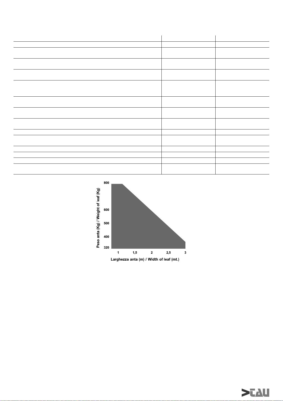
Lunghezza max anta \ Max. Flügellänge \ Max length of leaf \ Longueur max.
battant \ Longitud máx. hoja 3 mt 3 mt
Corsa utile \ Arbeitshub \ Useful travel \ Course utile \ Carrera útil 35 cm 35 cm
Temperatura di esercizio \ Betriebstemperatur \ Operating temperature \
Température de fonctionnement \ Temperatura de servicio Da –20 °C a +70 °C Da –20 °C a +70 °C
Peso \ Gewicht \ Weight \ Poids \ Peso 7 Kg. 7 Kg.
IP Motore \ Schutzart des Motor (IP) \ Motor IP \ IP Moteur \ IP Motor IP 13 IP 13
Ciclo di lavoro \ Arbeitzzyklus \ Work cycle \ Cycle de travail \ Ciclo de trabajo 100% 23%
Tempo corsa 90° \ Laufzeit, 90° \ 90° travel time \ Temps de course 90° \
Tiempo recorrido 90° 12 - 15 sec. 24 sec.
P2000
I - N.B.: In presenza di vento, per l’installazione su cancelli ad ante battenti cieche, non è garantito il funzionamento.
GB - N.B.: For The installation of blank swing gates, functioning cannot be gua-ranteed in the presence of wind.
D - N.B.: Bei Wind wird für die Installation an durchgehenden Flügel-toren der Betrieb nicht garantiert.
F - N.B.: En présence de vent, en cas d’installation sur des portails avec portes battantes pleines, le fonctionnement n’est
pas garanti.
E - N.B.: En presencia de viento, para la instalación en cancelas de hojas batientes cie-gas, no se garantiza el
funcionamiento.
6
P2000 Series
Page 7
MATERIALI PER L’INSTALLAZIONE (fi g.2)
1) Art.S-650P2000185: Staffa attacco anta zincata
2) Art.P-650/P2000/P2000B: Attuatore P2000/P2000B
3) Art.S-P2250SG190: Staffa grande zincata
4) Art.S-650P225050: Staffa angolare zincata.
ELEMENTI DELL’ATTUATORE (fi g.6)
SE IL PILASTRO E’ IN MURATURA (fi g.7):
usare n°3 tasselli M10 per fi ssare la staffa angolare al muro;
SE IL PILASTRO E’ METALLICO (fi g.7):
saldare accuratamente la staffa grande al cancello.
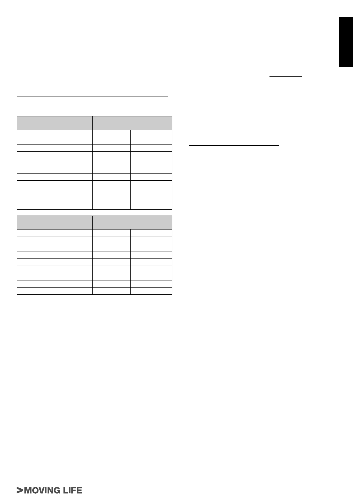
MISURE DA RISPETTARE (fi g.3, fi g.4 e fi g.5)
X° A B
90 140 ÷ 165 mm 145 mm 40 mm
90 140 ÷ 165 mm 150 mm 40 mm
90 140 ÷ 160 mm 155 mm 40 mm
90 140 ÷ 155 mm 160 mm 40 mm
90 140 ÷ 155 mm 165 mm 40 mm
90 140 ÷ 150 mm 170 mm 40 mm
90 140 ÷ 145 mm 175 mm 40 mm
90 140 ÷ 145 mm 180 mm 40 mm
90 140 mm 185 mm 40 mm
100 165 mm 145 mm 40 mm
100 165 mm 150 mm 40 mm
Spessore
cancello
forcella in direzione dei gusci fi no a che la staffa attacco anta
possa sovrapporsi alla posizione appena marcata sull’anta.
Se l’operazione è possibile l’installazione è corretta.
Questo metodo si può usare per stabilire dove fi ssare la staffa
attacco anta per ogni angolo di apertura (X°) voluto, a condizione
che ciò sia possibile (parametri A e B e corsa utile dell’attuatore
permettendo).
7_ fi ssare la staffa attacco anta nella posizione marcata.
Nota: per una completa sicurezza si fa obbligo di installare,
se non presenti, i fermi meccanici (battenti a pavimento) con
tappo in gomma in apertura e in chiusura (3 fi g.13), in modo
che intervengano subito prima dei fi ne-corsa meccanici del
pistone.
USO DELLO SBLOCCO MANUALE
1 - Inserire la chiave nello sblocco e ruotarla in senso orario.
2 - Tirare verso l’alto il tappo di plastica come da fi g.8.
3 - Tirare la leva verso l’alto e ruotarla in senso orario.
4 - Dopo aver richiuso il tappo di plastica, agire manualmente sul
cancello per aprire e chiudere.
N.B.: Effettuare le operazioni descritte all’inverso per
ribloccare il cancello (riabbassare la leva precedentemente
ruotata e
attivato per movimentare manualmente il cancello).
richiudere il tappo se si decide di lasciare lo sblocco
COLLEGAMENTO ELETTRICO AL MOTORE
Rimuovere le 4 viti di fi ssaggio e sollevare il coperchio plastico
come in fi g.9.
ITALIANO
X° A B
90 145 ÷ 170 mm 150 mm 50 mm
90 145 ÷ 165 mm 155 mm 50 mm
90 145 ÷ 160 mm 160 mm 50 mm
90 145 ÷ 160 mm 165 mm 50 mm
90 145 ÷ 155 mm 170 mm 50 mm
90 145 ÷ 150 mm 175 mm 50 mm
90 145 ÷ 150 mm 180 mm 50 mm
90 145 mm 185 mm 50 mm
100 170 mm 150 mm 50 mm
÷ = INTERVALLO TRA IL VALORE MINIMO E IL VALORE
MASSIMO CONSENTITI
Corsa utile = 350 mm
Nel caso in cui le dimensioni del pilastro o la posizione della cerniera
non permettano di contenere la quota B nella misura desiderata, è
necessario effettuare una nicchia sul pilastro come da fi g.5.
Spessore
cancello
INSTALLAZIONE
Rispettare i valori di tabella e oliare i cardini del cancello.
1_ Ancorare l’attuatore alla staffa grande (o angolare) usando la
vite in dotazione (vedi 1 fi g.7);
2_ verifi care la misura di 690 mm (fi g.4 - normalmente, l’attuatore
viene fornito già predisposto, eventualmente, se la misura
dovesse essere inferiore, portare il fi necosra meccanico - 27
fi gg.16-17 - in battuta sul tappo terminale agendo sui grani di
fi ssaggio e, collegando temporaneamente il motore - ad una
batteria per la versione in 12V o ad una pulsantiera per la
versione in 230V - portare la forcella in battuta sul fi necorsa
meccanico);
3_ fi ssare la staffa attacco anta alla forcella;
4_ appoggiare la staffa appena fi ssata all’anta del cancello
completamente chiuso e segnare i punti di fi ssaggio (avendo
cura della planarità, vedi fi g.3).
Prima di passare alla fase successiva eseguire la seguente
prova:
• aprire manualmente il cancello fi no all’angolo massimo voluto;
• utilizzando lo stesso metodo menzionato al punto 2, portare la
MODELLO P2000BENC
Collegare il cavo multipolare* ai morsetti di fi g.10, ricordando che:
cavo rosso sez. 2.5 mm²: fase motore
cavo blu sez. 2.5: neutro motore
cavo marrone sez. 0.5 mm²: positivo encoder
cavo blu sez. 0.5 mm²: negativo encoder
cavo bianco sez. 0.5 mm²: segnale encoder.
Usare esclusivamente centraline dotate di frizione elettrica.
* Si consiglia di utilizzare il cavo composto della TAU srl, cod. M-
03000010CO;
MODELLO P2000
1 - Collegarsi al morsetto di fi g.11 con cavi di sezione almeno
pari a 1.5 mmq provando il verso di rotazione del motore e
ricordando che:
cavo giallo-verde: massa
cavo blu: comune
cavo nero: fase
cavo marrone: fase
In prossimità della scheda elettronica di comando collegare il
2 -
condensatore in dotazione in parallelo alle 2 fasi del motore
facendo attenzione a non cortocircuitare i due fi li, al fi ne di
evitare possibili scariche dovute a correnti residue. Usare
esclusivamente centrali con frizione elettrica.
RACCOMANDAZIONI DI CARATTERE GENERALE
Integrare la sicurezza del cancello conformemente alla normativa
vigente.
Scegliere percorsi brevi per i cavi e tenere separati i cavi di potenza
dai cavi di comando.
Per la messa a punto della coppia massima del motoriduttore,
attenersi alle normative in vigore.
In accordo con la normativa europea in materia di sicurezza
si consiglia di collegare a monte dell’impianto un interruttore
automatico magnetotermico con In=6 A, al fi ne di poter garantire la
selettività in caso di manutenzione.
Verifi care che ogni singolo dispositivo installato sia effi ciente ed
effi cace.
Affi ggere cartelli facilmente leggibili che informino della presenza
del cancello motorizzato.
P2000 Series
7
Page 8

USO
Si fà espresso divieto di utilizzare l’apparecchio per scopi diversi
o in circostanze diverse da quelle menzionate. Normalmente,
la centralina elettronica installata (che deve avere la frizione
elettrica incorporata) consente di selezionare il funzionamento:
automatico : un impulso di comando esegue l’apertura e la
ITALIANO
chiusura del cancello
semiautomatico: un impulso di comando esegue l’apertura o la
chiusura del cancello.
In caso di mancanza di energia elettrica, il cancello può funzionare
ugualmente grazie alla possibilità di gestione manuale, per la
quale è necessario agire sul dispositivo di sblocco manuale. Il
modello P2000BENC, alimentabile con batteria tampone, è in
grado di effettuare almeno 15 cicli completi (apertura e chiusura)
in modo autonomo.
Si ricorda che si è in presenza di un dispositivo automatico e
alimentato con corrente, perciò nell’utilizzo devono essere usate le
dovute precauzioni. In particolare, si ammonisce di:
• non toccare l’apparecchio con mani bagnate e/o piedi bagnati
o nudi;
• togliere la corrente prima di aprire la scatola comandi e/o
l’attuatore;
• non tirare il cavo di alimentazione per staccare la presa di
corrente;
• non toccare il motore se non siete sicuri che sia raffreddato;
• mettere in movimento il cancello solo quando è completamente
visibile;
• tenersi fuori dal raggio di azione del cancello se questo è in
movimento: aspettare fi no a che non sia fermo;
• non lasciare che bambini o animali giochino in prossimità del
cancello;
• non lasciare che bambini o incapaci usino il telecomando o altri
dispositivi di azionamento;
• effettuare una manutenzione periodica;
• in caso di guasto, togliere l’alimentazione e gestire il cancello
manualmente solo se possibile e sicuro. Astenersi da ogni
intervento e chiamare un tecnico autorizzato.
MANUTENZIONE
Gli attuatori P2000/P2000BENC necessitano di poca
manutenzione; il loro buon funzionamento dipende dallo stato del
cancello: perciò descriveremo brevemente anche le operazioni da
fare per avere un cancello sempre effi ciente.
A TTENZIONE: nessuna persona ad eccezione del manutentore,
che deve essere un tecnico specializzato, deve poter
comandare l’automatismo durante la manutenzione.
Si raccomanda perciò di togliere l’alimentazione di rete, evitando
così anche il pericolo di shock elettrici. Se invece l’alimentazione
dovesse essere presente per talune verifi che, si raccomanda di
controllare o disabilitare ogni dispositivo di comando (telecomandi,
pulsantiere, etc.) ad eccezione del dispositivo usato dal
manutentore.
Manutenzione ordinaria
Ciascuna delle seguenti operazioni deve essere eseguita quando
se ne avverte la necessità e comunque ogni 6 mesi per un uso
domestico (circa 3000 cicli di lavoro) e ogni 2 mesi per un uso
intensivo, es. condominiale (sempre ogni 3000 cicli di lavoro).
Cancello:
- lubrifi care ed ingrassare i cardini del cancello.
Impianto di automazione:
- verifi care il corretto funzionamento dei dispositivi di sicurezza (
fotocellule, costa pneumatica, etc. ) con tempi e modi descritti
dai fornitori;
- ingrassare (con l’ingrassatore) la vite senza fi ne accessibile
dalla parte inferiore dell’attuatore (vedi fi g.12); si consiglia di
utilizzare grasso al sapone di litio complesso della SYNECO.
- verifi care lo stato di carica della batteria con un tester per batterie
piombo-acido; in caso di sostituzione utilizzare una batteria
originale e riciclare l’unità scarica secondo la normativa vigente
(in alternativa TAU consiglia di utilizzare batterie FIAMM).
Manutenzione straordinaria o rotture
Se dovessero rendersi necessari interventi non banali su parti
elettromeccaniche, si raccomanda la rimozione del componente
dove il guasto è localizzato per consentire una riparazione in
offi cina dai tecnici della casa madre o da essa autorizzati.
NOTA: Consigliamo di riporre tutta al documentazione relativa
all’impianto all’interno o nelle immediate vicinanze della
centralina.
IMPIANTO TIPO (fi g.13)
APPENDICE
CHE SP AZI DI SICUREZZA DEVO RISPETT ARE NEL RENDERE
UN CANCELLO AUTOMATICO?
• La distanza A fi g.14 fra stipite e il montante adiacente del
cancello deve essere costante durante la rotazione del cancello.
Se la distanza è variabile, la distanza deve essere ≥ 25 mm per
tutta l’altezza; se diversamente bisogna segregare lo spazio
reso così accessibile per tutta l’altezza del cancello fi no ad un
limite massimo di mt.2.5.
• La distanza B di fi g.14 fra pavimento ed anta deve essere ≥ 50
mm, se per pendenza del pavimento la distanza B è variabile,
è lasciata libertà all’installatore di adottare misure atte a ridurre
il pericolo di convogliamento.
• In un cancello a due ante, la distanza C di fi g.15 fra le due ante
chiuse, deve essere ≥ 2,5 cm; tale spazio può essere ricoperto
installando una costa pneumatica sul bordo di un’anta oppure
sistemando un elemento elastico deformabile nello spazio
libero. In alternativa, tale spazio può essere minore o nullo ma
bisogna realizzare uno sfasamento fra le ante in chiusura tale
da creare uno spazio D di fi g.15 di 50 cm.
CONSIGLI PER UN’INSTALLAZIONE SICURA
Funzionamento ad uomo presente: basta un arresto di
emergenza e un lampeggiante
Funzionamento automatico o semiautomatico: bisogna
installare un lampeggiante e regolare la coppia del motore come
descritto più avanti; se tale regolazione non è possibile occorre
installare una costa pneumatica.
• applicare due fotocellule, una all’esterno e una all’interno dalla
via di corsa per delimitare la zona di movimento del cancello.
Nel caso di sovrapposizione delle ante mediante profi lo di
battuta è obbligatorio sfalsarle (distanza D fi g.15).
Per ogni tipo di funzionamento: Se in apertura, l’anta si arresta
rispetto ad un ostacolo fi sso (muretto, parete, pilastro, etc.) ad una
distanza (E
sulla parte fi ssa una costa pneumatica secondo i seguenti criteri:
1- se si tratta di un ostacolo che si sviluppa preminentemente
in altezza (cioè in verticale) la costa si applica (su tutta la
lunghezza dell’ostacolo per cui è valida la condizione di cui
sopra) ad un’altezza compresa tra 40 e 60 cm dal pavimento
sottostante;
2- se si tratta di un ostacolo che si sviluppa preminentemente in
orizzontale ed ha altezza minore di 60 cm, la costa si applica a
5 cm dal bordo superiore dell’ostacolo.
fi g.15) minore di 40 cm, si deve applicare sull’anta o
CARATTERISTICHE, REGOLAZIONI E INSTALLAZIONE
DEI DISPOSITIVI DI SICUREZZA
Fotocellule :
• Vanno collocate ad un’altezza variabile tra i 40 e 60 cm del
suolo ed a una distanza max di cm 10 calcolata dal bordo
dell’anta aperta e dal fi lo del cancello chiuso.
Costa sensibile di sicurezza
• Nel caso più semplice previsto devono essere dei contatti
Normalmente Chiusi NC;
• La corsa elastica o deformazione minima deve essere maggiore
di almeno 1 cm dello spazio di arresto del cancello dal momento
dell’intervento del dispositivo
Limitatore di coppia
• Deve essere regolato in modo tale che l’anta si arresti in
presenza di una resistenza meccanica di 150 N (circa 15 Kg)
misurati sul suo bordo purché l’energia cinetica dell’anta sia
non superiore a 10 J.
8
P2000 Series
Page 9

INSTALLATION MATERIAL (fi g.2)
1) Art.S-650P200185: Galvanised leaf bracket
2) Art.P-650/P2000/P2000B: series P2000/P2000B actuator
3) Art.S-P2250SG190: Large galvanised bracket
4) Art.S-650P225050: Angular galvanised bracket
ACTUATOR PARTS (fi g.6)
BRICK PILLARS (fi g.7):
use n°3 M10 bolts to fi x the angular bracket to the wall;
METAL PILLARS (fi g.7):
weld the large bracket accurately to the gate.
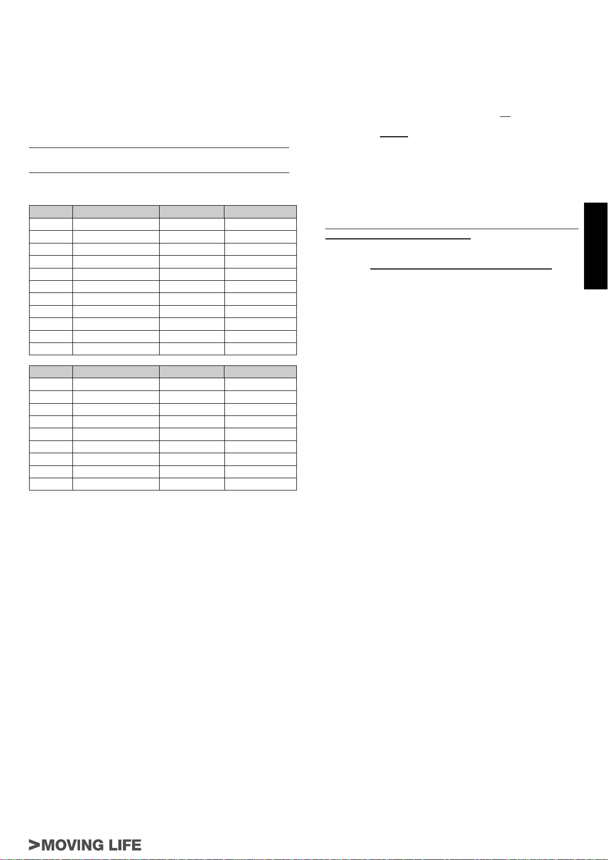
DIMENSIONS TO OBSERVE (fi g.3, fi g.4 and fi g.5)
X° A B
90 140 ÷ 165 mm 145 mm 40 mm
90 140 ÷ 165 mm 150 mm 40 mm
90 140 ÷ 160 mm 155 mm 40 mm
90 140 ÷ 155 mm 160 mm 40 mm
90 140 ÷ 155 mm 165 mm 40 mm
90 140 ÷ 150 mm 170 mm 40 mm
90 140 ÷ 145 mm 175 mm 40 mm
90 140 ÷ 145 mm 180 mm 40 mm
90 140 mm 185 mm 40 mm
100 165 mm 145 mm 40 mm
100 165 mm 150 mm 40 mm
X° A B
90 145 ÷ 170 mm 150 mm 50 mm
90 145 ÷ 165 mm 155 mm 50 mm
90 145 ÷ 160 mm 160 mm 50 mm
90 145 ÷ 160 mm 165 mm 50 mm
90 145 ÷ 155 mm 170 mm 50 mm
90 145 ÷ 150 mm 175 mm 50 mm
90 145 ÷ 150 mm 180 mm 50 mm
90 145 mm 185 mm 50 mm
100 170 mm 150 mm 50 mm
Thickness
of the gate
Thickness
of the gate
• using the same method as in point 2, position the fork in the
direction of the casings until the wing connection bracket is
over the position marked on the wing.
If the small bracket does cover the position marked it means
installation has been done correctly.
This method can be used to establish where the small bracket will
have to be welded for each opening angle (X°) requiredprovided
it is possible (parameters A and B and the actuator ’s useful travel
permitting).
7_ fi x the wing connection bracket in the marked position.
Note: for complete safety, the mechanical stops with rubber
cap (fl oor stops) must be fi tted in opening and closing of the
gate (3 fi g.13), in order that they intervene just before the
mechanical piston stops.
USE OF MANUAL UNLOCKING
1 - Insert the key into the release device and turn clockwise.
2 - Push up the plastic cap as shown in fi g.8.
3 - Pull up the lever and turn clockwise.
4 - After putting the plastic cap back on, the gate can be opened
and closed by hand.
N.B.: Carry out the above described operations in reverse
order to block the gate again (lower the lever previously
turned, and put the cap back to leave the device on for manual
operation).
ELECTRICAL CONNECTION TO THE MOTOR
Remove the 4 securing screws and lift the plastic cover as shown
in fi g.9.
MODEL P2000BENC
Connect the multicore* cable to the terminals in fi g.10, bearing in
mind that:
2.5 mm² sect. red wire: motor phase
2.5 mm² sect. blue wire: motor neutral
0.5 mm² sect. brown wire: encoder positive
0.5 mm² sect. blue wire: encoder negative
0.5 mm² sect. white wire: encoder signal.
Only use control units fi tted with an electric clutch.
* TAU srl recommends its composite cable, Code M-
03000010CO;
ENGLISH
÷ = RANGE BETWEEN PERMITTED MINIMUM AND
MAXIMUM VALUES
Useful travel = 350 mm
If the dimensions of the gate post or position of the hinge do not
allow for the specifi ed distance of “B”, make a recess in the gate
post as shown in fi g.5.
INSTALLATION
Please keep to the values given in the table and oil the gate’s
hinges.
1_ Anchor the actuator to the large bracket (or angular bracket)
using the screw provided (see 1 fi g.7);
2_ check the measurement of 690 mm (fi g. 4 – the actuator is
normally prepared when supplied, if the measurement is less,
position the mechanical stop - 27 fi g. 16-17 – against the end
cap by means of the fi xing screw and, temporarily connecting
the motor to a battery for the 12 V version or a push-button
panel for the 230 V version, position the fork up against the
mechanical stop);
3_ fi x the wing connection bracket to the fork;
4_ rest the bracket that has just been fi xed, onto the wing of the
completely closed gate and mark the fi xing points (make sure it
is level, see fi g. 3).
Before going on to the next phase please carry out the following
test:
• manually open the gate to the maximum required angle;
MODEL P2000
1 - Connect wires with a cross-section of at least 1.5 mm² to the
terminal in fi g.1 1, checking the direction of rotation of the motor
and bearing in mind that:
yellow-green wire: earth;
blue wire: common;
black wire: phase;
brown wire: phase.
2 - Connect up the condenser supplied in proximity to the electronic
control card. The said condenser must be parallel to the 2
phases of the motor. W arning! Do not short-circuit the two wires
as this may cause discharges because of the current remaining
in the wires. Use control units with torque limiting device only.
GENERAL ADVICE
Install a gate safety system in compliance with current
regulations.
Choose short routes for cables and keep power cables separate
from control cables.
Please refer to current regulations when setting the maximum
torque value of the gear motor.
As required by European safety standards, install a 6 Amp circuit
breaker up-line from the system in order to disconnect the power
supply when servicing the gate.
Check that each single device installed is effi cient and effective.
Put up legible signs warning of the presence of a motorised gate.
P2000 Series
9
Page 10

USE
It is expressly forbidden to use the device for any other
purposes or under any other circumstances other than those
mentioned. The electronic control unit (which must be fi tted with
an electric clutch) allows the following functions to be selected:
automatic : a command impulse opens and shuts the gate
semiautomatic : a command impulse opens or shuts the gate.
In the event of a power failure, the gate may be moved manually
by activating the “manual release” device. Mod. P2000BENC can
be powered by a buffer battery and is able to perform at least 15
complete cycles (open and close) on its own.
This is an electrically powered automatic device and should
therefore be used with care. In particular:
• do not touch with wet hands and/or wet or bare feet;
ENGLISH
• disconnect the power supply before opening the control box
and/or the actuator;
• do not pull the plug out by its cable;
• do not touch the motor unless you are certain it is cool;
• only operate the gate when it is completely visible;
• do not approach the gate while it is moving;
• do not allow children or animals to play near the gate;
• do not allow children or disabled people to use the remote
control or other operating devices;
• carry out routine maintenance;
• in the case of a fault, disconnect the power supply and only
move the gate if it is possible and safe to do so. Do not touch
the gate and call in an authorised technician.
ANNEX
SAFETY DISTANCES FOR AUTOMATIC GATES?
• The distance A (fi g.14) between the jamb and the upright next
to the gate must remain constant when the gate rotates. If this
varies, the distance must be ≥ 25 mm up the whole height of
the gate; if this is not the case, fi ll in the extra space for the total
height of the gate up to a maximum of 2.5 m.
• The distance B (fi g.14) between the fl oor and the leaf must
be ≥ 50 mm, if distance B varies due to sloping ground, the
fi tter must take steps to reduce the danger of people or objects
getting trapped.
• In a two-leaf gate, the distance C (fi g.15) between the two
closed leafs must be ≥ 2,5 cm; this space can be covered by
installing a pneumatic edge on the side of the leaf or fi tting a
deformable fl exible element in the free space. If this space is
smaller or absent, the two leafs must be closed in sequence so
as to leave a clearance D (fi g.15) of 50 cm.
SAFE INSTALLATION HINTS
Man present operation: an emergency stop device and a fl ashing
light is suffi cient
Automatic or semiautomatic operation: install a fl ashing light
and adjust motor torque as described below; if this is not possible,
fi t a pneumatic edge.
• fi t one photocell at both gate’s sides thus limiting the gate’s
operating range. If the leafs overlap due to a stop profi le they
must be put out of phase (distance D fi g.15).
MAINTENANCE
The P2000/P2000BENC actuators need very little maintenance.
However, as the gate must be in good working order for them to
work properly , the operations required to keep it in perfect condition
are described below.
ATTENTION: no-one, except for the maintenance man, who
must be a specialised technician, must be able to use the
automatic system during maintenance.
Switch off the mains power supply to eliminate the risk of
electrocution. If the power supply must be left on for certain
operations, each control device should be checked or disabled
(remote controls, push button strips, etc.) except for the one used
by the maintenance man.
Routine maintenance
Each of the following operations must be carried out when
necessary and always every 6 months for domestic use (approx.
3000 work cycles) and every 2 months for intensive use such as
blocks of fl ats (always 3000 work cycles).
Gate:
- lubricate and grease the hinges of the gate.
Automation system:
- check the safety devices (photocells, pneumatic edge, etc.)
work according to the manufacturer’s instructions;
- grease (with a greaser) the worm screw from underneath the
actuator (see fi g.12); TAU srl recommends using the complex
lithium soap grease produced by SYNECO.
- use a tester for lead-acid batteries to check whether the
battery is charged; if it needs replacing use an original battery
and recycle the fl at one in compliance with current legislation
(alternatively, TAU srl recommends using FIAMM batteries).
For all operation types: If the leaf stops during the opening phase
at a distance (E fi g.15) of less than 40 cm with respect to a fi xed
obstacle (wall, pillar, etc.), a pneumatic edge must be fi tted to the
leaf or the fi xed part as follows:
1 - if the obstacle is higher than it is wide apply the edge (for the
whole length of the obstacle) at a height of between 40 and 60
cm from the ground;
2 - if the obstacle is wider than it is high and is lower than 60cm
apply the edge 5 cm from the upper edge of the obstacle.
CHARACTERISTICS, ADJUSTMENT AND INSTALLATION
OF SAFETY DEVICES
Photocells :
• These are fi tted at a height varying from 40 and 60 cm from the
ground at a max. distance of 10 cm calculated from the edge of
the open leaf and from the edge of the closed gate.
Sensitive safety edge
• In the simplest cases there must be Normally Closed (NC)
contacts;
• Minimum deformation must be at least 1 cm greater than the
stopping distance of the gate from when the device cut in
Torque limiting device
• This must be adjusted so that the gate stops in the presence
of a mechanical resistance of 150 N (about 15 Kg) measured
on its edge as long as the kinetic force of the leaf is not greater
than 10 J.
Extraordinary maintenance or breakage
If major work on electromechanical parts must be carried out, the
faulty component should be removed and repaired in the workshop
by the maker’s or other authorised technicians.
N.B.: Keep all the documents concerning the system inside
or near the control unit.
TYPICAL SYSTEM (fi g.13)
10
P2000 Series
Page 11
INSTALLATIONSMATERIALIEN (Abb.2)
1) Art. S-650P2000185: Verzinkter Torfl ügelbefestigungsbügel
2) Art.P-650/P2000/P2000B: Antrieb Serie P2000/P2000B
3) Art.S-P2250SG190: groâer verzinkter Bügel
4) Art.S-650P225050: Verzinkter Winkelbügel
TEILE DES ANTRIEBS (Abb.6)
WENN DER PFEILER GEMAUERT IST (Abb.7):
Nr. 3 M10 Dübel verwenden, um den Winkelbügel an der Mauer
zu befestigen.
WENN DER PFEILER AUS METALL IST (Abb.7):
Den großen Befestigungsbügel sorgfältig am Tor anschweißen.
ZU BEACHTENDE MAßE (Abb.3, Abb.4, und Abb.5)
X° A B Tordicke
90 140 ÷ 165 mm 145 mm 40 mm
90 140 ÷ 165 mm 150 mm 40 mm
90 140 ÷ 160 mm 155 mm 40 mm
90 140 ÷ 155 mm 160 mm 40 mm
90 140 ÷ 155 mm 165 mm 40 mm
90 140 ÷ 150 mm 170 mm 40 mm
90 140 ÷ 145 mm 175 mm 40 mm
90 140 ÷ 145 mm 180 mm 40 mm
90 140 mm 185 mm 40 mm
100 165 mm 145 mm 40 mm
100 165 mm 150 mm 40 mm
X° A B Tordicke
90 145 ÷ 170 mm 150 mm 50 mm
90 145 ÷ 165 mm 155 mm 50 mm
90 145 ÷ 160 mm 160 mm 50 mm
90 145 ÷ 160 mm 165 mm 50 mm
90 145 ÷ 155 mm 170 mm 50 mm
90 145 ÷ 150 mm 175 mm 50 mm
90 145 ÷ 150 mm 180 mm 50 mm
90 145 mm 185 mm 50 mm
100 170 mm 150 mm 50 mm
÷ = INTERVALL ZWISCHEN ZULÄSSIGEM MINDEST- UND
HÖCHSTWERT
Arbeitshub = 350 mm
Falls das Maß B wegen der Abmessungen des Pfeilers bzw. der
Position des Scharniers die Tabellenvorgabe übersteigen sollte,
muß eine Ausspaarung am Pfeiler nach Abb.5 angefertigt werden.
INSTALLATION
Die Werte der T abelle einhalten und Die Stützzapfen des Gittertores
ölen.
1_ Den Kolbentorantrieb an dem großen Bügel (oder Winkelbügel)
verankern; dazu die sich in der Ausstattung befi ndliche
Schraube verwen den (siehe 1 Abb.7).
2_ das Maß 690 mm überprüfen (Abb.4 – gewöhnlich wird der
Antrieb bereits eingestellt geliefert; sollte das Maß kleiner sein,
den mechanischen Endschalter - 27 Abb.16-17 – ggf. bis zum
Anschlag am Endstopfen verschieben, indem die Befestigungs
stiftschrauben betätigt werden, dann die Gabel so positionieren,
dass sie am mechanischen Endschalter anschlägt, indem der
Motor vorübergehend an einer Batterie (12 V Version) oder
einer Tastatur (230 V Version) angeschlossen wird);
3_ den Toranschlussbügel an der Gabel befestigen;
4_ den soeben befestigten Bügel auf den ganz geschlossenen
Torfl ügel legen und die Befestigungsstellen markieren (die
Ebenheit beachten – siehe die Abb. 3).
Bevor zu der nachfolgenden Arbeitsphase übergegangen wird,
sollte der folgende Versuch durchgeführt werden:
das Tor bis zum gewünschten maximalen Winkel von Hand öffnen;
•
• die Gabel auf dieselbe Weise wie in Punkt 2 in Gehäuserichtung
verschieben, bis sich der Toranschlussbügel mit den soeben
am Torfl ügel markierten Stellen überlagern kann.
Ist dieser Vorgang möglich, ist die Installation korrekt.
Diese Methode kann auch verwendet werden, um festzulegen,
wo der kleine Befestigungsbügel für den jeweils gewünschten
Öffnungswinkel (X°) angeschweißt werden soll; Bedingung ist
jedoch, daß dies möglich ist (Parameter A und B und Arbeitshub
des Kolbentorantriebs müssen dies erlauben).
7_ den Toranschlussbügel an der markierten Stelle befestigen.
BITTE BEMERKEN: für höchste Sicherheit ist die Installation
der mechanischen Bodenendanschläge im Auf und Zu mit
Gummistopfen Pfl icht (3 Abb.13), so dass diese gleich vor
den mechanischen endschaltern des kolbens eingreifen.
VERWENDUNG DER MANUELLEN ENTRIEGELUNG
1 - Den Schlüssel in die Entriegelung stecken und im Uhrzeigersinn
drehen.
2 - Den Plastikstopfen nach oben ziehen, wie in Abb.8.
3 - Den Hebel nach oben ziehen und ihn im Urzeigersinn drehen.
4 - Nachdem der Plastikverschluss wieder geschlossen ist, das
Tor von Hand öffnen bzw. schließen.
N.B.: Die beschriebenen Vorgänge umgekehrt ausführen, um
das Tor wieder zu blockieren (den vorher gedrehten Hebel
senken und den Plastikverschluss wieder schließen, falls
man die Entriegelung für die manuelle Verschiebung des Tors
aktiviert lassen will).
ELEKTRISCHER ANSCHLUß AN DEN MOTOR
Die 4 Befestigungsschrauben entfernen und den Plastikdeckel
heben, wie in Abb.9.
MODELLE P2000BENC
Das mehrpolige Kabel* an den Klemmen in Abb.10 anschließen,
dabei folgendes beachten:
rotes Kabel Querschn. 2.5 mm²: Motorphase
Blaues Kabel Querschn. 2.5 mm²: Motornullleiter
braunes Kabel Querschn. 0.5 mm²: Pluspol Encoder
blaues Kabel Querschn. 0.5 mm²: Minuspol Encoder
weißes Kabel Querschn. 0.5 mm²: Encodersignal.
Ausschließlich Steuerungen verwenden, die mit elektrischer
Kupplung ausgestattet sind.
* Es wird empfohlen, das von der Firma T AU srl zusammengebaute
Kabel Code M-03000010CO zu benutzen;
MODELLE P2000
1 - Den Anschluss an die Klemme, Abb.1 1, mit Kabeln durchführen,
die einen Querschnitt von mindesten 1.5 mm² aufweisen, die
Drehrichtung des Motors überprüfen und folgendes beachten:
gelb-grünes Kabel: Erde
blaues Kabel: gemeinsamer Leiter
schwarzes Kabel: Phase
braunes Kabel: Phase
2 - Den mitgelieferten Kondensator in der Nähe der elektronischen
Steuerkarte mit den 2 Phasen des Motors parallel schalten,
dabei die beiden Drähte nicht kurzschließen, um mögliche
Entladungen aufgrund von Restströmen zu vermeiden.
Ausschließlich Steuerzentralen mit elektrischer Kupplung
verwenden.
ALLGEMEINE EMPFEHLUNGEN
Die Sicherheit des Tors gemäß der gültigen Vorschriften
integrieren.
Es sollten kurzen Strecken für die Kabel gewählt und die
Leistungskabel von den Steuerkabeln getrennt gehalten werden.
Für die Einstellung des maximalen Drehmomentes des
Getriebemotors sind die gültigen Vorschriften einzuhalten.
In Übereinstimmung mit den europäischen Sicherheitsnormen wird
die Installation eines magnetothermischen Automatikschalters mit
In=6 A vor der Anlage empfohlen, um die Stromversorgung im
Falle von Wartung unterbrechen zu können.
Überprüfen, ob jede einzelne installierte Vorrichtung leistungsfähig
und wirksam ist.
Leicht lesbare Schilder anbringen, die darüber informieren, dass
ein motorisiertes Tor vorhanden ist.
DEUTSCH
P2000 Series
11
Page 12

GEBRAUCH
Es wird ausdrücklich verboten, die Vorrichtung für andere
Zwecke oder unter Umständen einzusetzen, die von den
genannten abweichen. Normalerweise ermöglicht die installierte
elektronische Steuerzentrale (die eine eingebaute elektrische
Kupplung haben muss) die Wahl folgender Funktionen:
Automatisch : ein Steuerimpuls führt das Öffnen und das
Schließen des Gittertores durch.
Halbautomatisch : ein Steuerimpuls führt das Öffnen oder
das Schließen des Gittertores durch.
Bei Stromausfall kann das Tor nach Betätigung der Vorrichtung
„manuelle Entriegelung” auch von Hand funktionieren. Das
über Pufferbatterie speisbare Modell P2000BENC ist imstande,
mindestens 15 vollständige Zyklen (Öffnung und Schließung)
selbständig auszuführen.
Es wird daran erinnert, dass es sich um eine automatische
Vorrichtung handelt, die mit Strom gespeist wird und daher mit
Vorsicht zu verwenden ist. Im besonderen wird vor folgendem
gewarnt:
• die Vorrichtung nicht mit feuchten Händen und/oder feuchten
oder nackten Füßen berühren;
• die Stromversorgung abschalten, bevor das Steuergehäuse
und/oder der Getriebemotor geöffnet werden;
• nicht am Stromkabel ziehen, um den Stecker zu ziehen;
DEUTSCH
• den Motor nicht berühren, wenn Sie sich nicht sicher sind, dass
er abgekühlt ist
• das Gittertor nur in Bewegung setzen, wenn es vollständig
sichtbar ist;
• außerhalb des Aktionsbereichs des Tors bleiben, wenn es sich
bewegt: warten, bis keine Bewegung mehr erfolgt;
• Kinder oder Tiere nicht in Tornähe spielen lassen;
• Kinder oder unfähige Personen nicht die Fernsteuerung oder
andere Vorrichtungen für die Betätigung verwenden lassen;
• eine regelmäßige Wartung ausführen;
• im Falle eines Defekts, die Stromversorgung abschalten und
das Tor, nur falls möglich uns sicher , von Hand bewegen. Keine
Eingriffe selbst ausführen, sondern sich an einen autorisierten
Techniker wenden.
WARTUNG
Die Antriebe P2000/P2000BENC erfordern wenig Wartung; ihr
guter Betrieb hängt auch von dem Zustand des Tors ab: aus
diesem Grunde beschreiben wir kurz auch die Tätigkeiten, die
durchzuführen sind, um das Tor immer leistungsfähig zu halten.
ACHTUNG: Achtung: niemand mit Ausnahme des
Wartungsmannes, der ein Fachtechniker sein muss, ist befugt,
die Automatisierung während der Wartung zu steuern.
Es wird daher empfohlen, die Netzstromversorgung abzuschalten,
wodurch auch die Stromschlaggefahr vermieden wird. Falls die
Versorgung dagegen für bestimmte Überprüfungen eingeschaltet
sein muss, so sind alle Steuervorrichtungen (wie Fernbedienungen,
Druckknopftafeln, usw.) mit Ausnahme der vom Wartungsmann
benutzten Vorrichtung zu deaktivieren.
Gewöhnliche Wartung
Jede der folgenden Arbeiten muss wenn nötig und mindestens
alle 6 Monate für den normalen Hausgebrauch (ungefähr 3000
Arbeitszyclen) und alle 2 Monate für den intensiven Gebrauch z.
B. Wohnblockbetrieb (immer ungefähr 3000 Arbeitszyklen).
Tor:
- die Angelzapfen des Tors schmieren und einfetten.
Automatisierungsanlage:
- Den einwandfreien Betrieb der Sicherheitsvorrichtungen
(Photozellen, Sicherheitsleiste, etc.) in Zeiten und auf die
Weisen überprüfen, die von den Herstellern vorgeschrieben
werden;
- Die vom unteren Teil des Antriebs aus erreichbare Schnecke
einfetten (mit Fettbüchse, siehe Abb.12); der Gebrauch von
SYNECO Lithiumseifenfett wird empfohlen.
- Den Ladestand der Batterie mit einem Testgerät für BleiSäure-Batterien überprüfen; im Falle eines Austausches eine
Originalbatterie verwenden und die leere Einheit gemäß der
gültigen Vorschriften entsorgen (anstelle der Originalbatterie
empfi ehlt die Firma TAU den Gebrauch von FIAMM Batterien).
Außergewöhnliche Wartung oder wichtige Störungen
Falls schwierigere Arbeiten an elektromechanischen Teilen
erforderlich sein sollten, wird die Entfernung des defekten Teils
empfohlen, damit eine Reparatur in der Werkstatt durch die
Herstellertechniker oder autorisierte Techniker erfolgen kann.
BITTE BEMERKEN: Wir empfehlen, alle Unterlagen der
Anlage in der Steuerzentrale oder in ihrer
unmittelbaren Nähe aufzubewahren.
ANLAGE TYP (Abb.13)
NACHTRAG
WELCHE SICHERHEITSFREIRÄUME MUSS ICH EINHALTEN,
WENN ICH EIN TOR AUTOMATISIERE?
• Der Abstand A, Abb.14, zwischen Pfosten und Ständer neben
dem Tor muss während der Tordrehung gleich bleiben. Ändert
sich der Abstand, so muss der Höchstabstand in der gesamten
Höhe ≥ 25 mm sein, andernfalls muss der so zugänglich
gewordene Raum in der gesamten Torhöhe bis max. 2,5 m
ausgefacht werden.
• Der Abstand B in Abb.14 zwischen Boden und Torfl ügel
muss ≥ 50 mm sein; falls der Abstand B aufgrund der
Neigung des Bodens variabel ist, so ist es dem Installateur
überlassen, Maßnahmen zur Reduzierung der Mitnehmgefahr
anzuwenden.
• An einem zweiteiligen Tor muss der Abstand C in Abb.15
zwischen den beiden geschlossenen Torfl ügeln ≥ 2,5 cm sein;
dieser Abstand kann mit einer Sicherheitsleiste an der Kante
des einen Torfl ügels oder einem verformbaren, elastischen
Element im Freiraum zugedeckt werden. Der Abstand kann
auch kleiner oder gleich Null sein, in diesem Fall müssen sich
die Torfl ügel aber verstellt schließen, so dass ein Raum D von
50 cm, Abb.15 entsteht.
HINWEISE FÜR EINE SICHERE INSTALLATION
Totmannbetrieb: es genügt eine Notstopvorrichtung und eine
Blinkleuchte
Automatischer / halbautomatischer Betrieb: eine Blinkleuchte
muss installiert werden, und der Motordrehmoment muss wie
später beschrieben eingestellt werden; falls diese Einstellung nicht
möglich ist, muss eine Sicherheitsleiste installiert werden.
• zwei Fotozellen anbringen, die eine außerhalb und die andere
innerhalb des Laufwegs, um den Bewegungsbereich des
Tors einzugrenzen. Im Falle einer Überlagerung der Tor fl ügel
mit Anschlagleiste müssen sie verstellt angebracht werden
(Distanz D Abb.15).
Für jede Betriebsweise: Wenn der Torfl ügel in Öffnung an einem
festen Hindernis (kleine Mauer, Wand, Pfeiler, usw.) mit einem
Abstand (E Abb.15) anhält, der kleiner als 40 cm ist, so muss am
Torfl ügel oder am festen T eil eine Sicherheitsleiste nach folgenden
Kriterien angebracht werden:
1 - wenn es sich um ein Hindernis handelt, dass sich
vorherrschend in der Höhe (also senkrecht) ausdehnt, so
wird die Sicherheitsleiste (in der ganzen Länge des oben
genannten Hindernisses) in einer Höhe zwischen 40 und 60
cm ab Fußboden angebracht;
2 - wenn es sich um ein Hindernis handelt, dass sich vorherrschend
in der Breite (also waagerecht) ausdehnt und eine Höhe unter
60 cm hat, so wird die Sicherheitsleiste 5 cm ab der oberen
Kante des Hindernisses angebracht.
MERKMALE, EINSTELLUNGEN UND INSTALLATION
DER SICHERHEITSVORRICHTUNGEN
Photozellen :
• Sie werden auf einer Höhe zwischen 40 und 60 cm ab Boden
und in einem Höchstabstand von 10 cm ab Kante des geöffneten
Torfl ügels und ab Rand des geschlossenen Tors angebracht.
Sensible Sicherheitsleiste
• Im einfachsten Fall muss es sich um gewöhnlich geschlossene
NC-Kontakte handeln;
• Die Elastizität bzw. Mindestverformung muss mindestens 1
cm größer sein als der Raum, den das Tor ab Ansprechen der
Vorrichtung zum Stillstand benötigt.
Drehmomentbegrenzer
• Muss so eingestellt werden, dass der Torfl ügel bei Vorhandensein
eines mechanischen Widerstands von 150 N (ca. 15 kg), an
seiner Kante gemessen, anhält, wobei die kinetische Energie
des Torfl ügels nicht größer als 10 J sein darf.
12
P2000 Series
Page 13

Italiano
ISTRUZIONI ED AVVERTENZE DESTINATE ALL’UTILIZZATORE DELL’AUTOMAZIONE
COMPLIMENTI per aver scelto per la vostra automazione un prodotto Tau!
Tau S.r.l. produce componenti per l’automazione di cancelli, porte, barriere, serramenti: motoriduttori, centrali di comando, radiocomandi, lampeggianti,
fotocellule e accessori.
I prodotti Tau sono realizzati solo con materiali e lavorazioni di qualità e, come azienda, siamo alla costante ricerca di soluzioni innovative che
semplifi chino sempre più l’utilizzo delle nostre apparecchiature, curate sotto ogni aspetto (tecnico, estetico ed ergonomico): nella grande gamma Tau il
vostro installatore può scegliere il prodotto che meglio soddisfa le vostre esigenze.
Tau però non produce la vostra automazione che, invece, è il risultato di un’opera di analisi, di valutazione, di scelta dei materiali e realizzazione
dell’impianto eseguita dal vostro installatore di fi ducia.
Ogni automazione, pertanto, è unica e solo il vostro installatore può eseguire un impianto secondo le vostre esigenze (in quanto dotato dell’esperienza
e della professionalità necessarie), sicuro ed affi dabile nel tempo; e soprattutto a regola d’arte, rispondente cioè alle normative in vigore.
Un impianto di automazione è una bella comodità, oltre che un valido sistema di sicurezza e, con poche, semplici attenzioni, è destinato a durare negli
anni.
Anche se l’automazione in vostro possesso soddisfa il livello di sicurezza richiesto dalle normative, questo non esclude l’esistenza di un “rischio residuo”,
cioè la possibilità che si possano generare situazioni di pericolo, dovute ad un utilizzo incosciente e/o errato. Per questo motivo riportiamo alcuni consigli
sui comportamenti da tenere per evitare ogni inconveniente:
- Al primo utilizzo: chiedete al vostro installatore di spiegarvi l’origine dei rischi residui e leggete il presente manuale di istruzioni ed avvertenze per
l’utilizzatore consegnatovi dall’installatore. Conservate il manuale per qualsiasi problema futuro e ricordatevi di consegnarlo ad un eventuale nuovo
proprietario dell’impianto.
- L’impianto di automazione esegue fedelmente i vostri comandi: un uso incosciente e/o improprio può divenire pericoloso. Evitate quindi di
azionare l’automazione quando nel suo raggio d’azione si trovino persone, animali e/o cose.
- NON È UN GIOCO! Fate in modo che i bambini non giochino in prossimità dell’impianto e tenete i telecomandi fuori della loro portata.
- Anomalie: ad ogni comportamento anomalo dell’impianto, togliete l’alimentazione elettrica all’automazione ed eseguite lo sblocco manuale (come
da fi gura). Evitate qualsiasi intervento personale e chiamate il vostro installatore: una volta sbloccato, l’impianto funzionerà manualmente come
prima dell’installazione.
- Manutenzione: per durare nel tempo e funzionare in completa sicurezza, come qualsiasi altro macchinario, l’impianto necessita di una periodica
manutenzione. Stabilite insieme al vostro installatore i tempi di tale manutenzione. Tau consiglia un intervento ogni 6 mesi per un normale uso
domestico, che può variare in funzione dell’intensità d’uso (sempre ogni 3000 cicli di lavoro).
N.B. Qualsiasi tipo di intervento (controllo, manutenzione e/o riparazione) deve essere eseguito solo da personale qualifi cato.
- Non modifi care l’impianto, nè i relativi parametri di programmazione e di regolazione: la responsabilità è dell’installatore.
N.B. Il collaudo fi nale, le manutenzioni periodiche e le eventuali riparazioni devono essere documentate (negli appositi spazi) da chi le esegue
e i documenti conservati dal proprietario dell’impianto (IN CASO DI MANCATA DOCUMENTAZIONE LA GARANZIA DECADE).
- Smaltimento: al termine della vita dell’impianto assicuratevi che lo smantellamento venga eseguito da personale qualifi cato e che i materiali
vengano riciclati o smaltiti secondo le norme valide a livello locale.
Infi lare la chiave nello sblocco e ruotarla in senso orario.
Tirare verso l’alto il tappo di plastica come da fi gura.
La manovra manuale deve essere eseguita SOLO a porta ferma e DOPO aver tolto l’alimentazione alla centrale elettrica.
Nota: se il vostro impianto è dotato di un telecomando che dopo qualche tempo vi sembra funzionare peggio, oppure non funzionare
affato, potrebbe semplicemente dipendere dall’esaurimento della pila (a seconda del tipo, possono trascorrere diversi mesi fi no a 2/3
anni). Ve ne potete accorgere dal fatto che la spia di conferma della trasmissione è debole, oppure si accende solo per un breve istante.
Prima di rivolgervi all’installatore provate a scambiare la pila con quella di un altro trasmettitore eventualmente funzionante: se questa
fosse la causa dell’anomalia, sarà suffi ciente sostituire la pila con un’altra dello stesso tipo.
Nel caso voleste aggiungere nella vostra casa un nuovo tipo di automazione, rivolgendovi allo stesso installatore e alla Tau vi garantirete,
oltre che la consulenza di uno specialista e i prodotti più evoluti del mercato, il migliore funzionamento e la massima compatibilità delle
automazioni.
Vi ringraziamo per aver letto queste raccomandazioni, e vi auguriamo la massima soddisfazione dal vostro nuovo impianto: per ogni tipo
di esigenza rivolgetevi con fi ducia al vostro installatore.
Tirare la leva verso l’alto e ruotarla in senso orario.
Dopo aver richiuso il tappo di plastica, agire manualmente sul
cancello per aprire e chiudere.
P2000 Series
1
Page 14

English
INSTRUCTIONS AND WARNINGS FOR AUTOMATIC SYSTEM USERS
CONGRA TULATIONS on choosing a Tau product for your automation system!
T au S.r .l. produces components for automatic gates, doors, barriers and shutters. These include gear motors, control units, radio control devices, fl ashing
lights, photocells and accessories.
T au products are exclusively made with top quality materials and processes and, as a company , we constantly research and develop innovative solutions
in order to make our equipment increasingly easier to use. We also pay great attention to all details (technology, appearance and ergonomics). The
extensive Tau range makes it possible for your fi tter to choose the product which best meets your requirements.
Tau, however, does not produce your automated system as this is the outcome of a process of analysis, evaluation, choice of materials and installation
performed by your fi tter.
Each automated system is unique, therefore, and only your fi tter has the experience and professionalism required to create a system that is tailor-made
to your requirements, featuring long-term safety and reliability , and, above all, professionally installed and compliant with current regulations.
An automated system is handy to have as well as being a valid security system. Just a few, simple operations are required to ensure it lasts for years.
Even if your automated system satisfi es regulatory safety standards, this does not eliminate “residue risks”, that is, the possibility of dangerous situations
being generated, usually due to irresponsible and/or incorrect use. For this reason we would like to give you some suggestions on how to avoid these
risks:
- Before using the system for the fi rst time: ask your fi tter to explain how residue risks can arise and read the instructions and warnings in the user
handbook that your fi tter will have given you. Keep this manual for future use and, if you should ever sell your automated system, hand it over to the
new owner.
- Your automated system carries out your commands to the letter: irresponsible and/or incorrect use may cause it to become dangerous. Do not
use the system if people, animals and/or objects enter its operating area.
- IT IS NOT A T OY! Make sure children do not play near the system and keep the remote control device out of their reach.
- Faults: If you notice any abnormal behaviour, disconnect the system from the power supply immediately and perform the manual release operation
(see fi gure). Do not attempt to repair the door but call in your fi tter: the system will operate manually as it did before installation.
- Maintenance: to ensure long life and totally safe operation, the system required routine maintenance, just like any other piece of machinery.
Establish maintenance times together with your fi tter. Tau recommends a frequency of 6 months for normal domestic installations but this may vary
depending on the intensity of use (always every 3000 work cycles).
N.B.: All controls, maintenance work and/or repairs may only be carried out by qualifi ed personnel.
- Do not modify the plant or the relative programming and adjustment parameters: your fi tter will see to that.
N.B. Final testing, routine maintenance and any repairs must be documented by the fi tter (in the relative spaces) and such documents kept
by the owner of the system (IF THE DOCUMENTS ARE NOT PRODUCED, THE W ARRANTY WILL EXPIRE).
- Disposal: At the end of system life, make sure that it is demolished by qualifi ed personnel and that the materials are recycled or disposed of
according to local regulations.
Put the key into the lock and turn it clockwise.
Pull the plastic cup, as shown in fi gure.
The manual manoeuvre must ONLY be done with the door stopped and AFTER disconnecting power from the electrical control unit.
N.B.: if your remote control unit (if supplied) starts working badly after a time, or does not work at all, the batteries may be fl at (they can last from
several months to 2/3 years depending on what type is used). This can be seen from the fact that the transmission confi rmation LED gets dimmer
or only turns on for brief moments. Before contacting your fi tter, try exchanging the battery with one from a good transmitter: if this is the reason
for the fault, simply replace the battery with another one of the same type.
If you wish to add a new automated system to your house, contact your fi tter and we at Tau to have the advice of a specialist, the most developed
products on the market, best operation and maximum automation compatibility.
Thank you for reading these suggestions and we trust you are fully satisfi ed with your new system: please contact your fi tter for any further
requirements.
2
P2000 Series
After putting the plastic cap back on, the gate can be opened
Pull the lever up and turn it clockwise.
and closed by hand.
Page 15

Deutsch
ANWEISUNGEN UND HINWEISE FÜR DEN BENUTZER DER AUTOMATISIERUNG
WIR GRA TULIEREN IHNEN zur W ahl eines Tau Produktes für Ihre Automatisierung!
Tau S.r.l. stellt Komponenten für die Automatisierung von Toren, Türen, Schranken und Fenstern her: Getriebemotoren, Steuerzentralen,
Funksteuerungen, Blinkleuchten, Fotozellen und Zubehör.
Die Tau Produkte werden nur mit Materialien und Bearbeitungen hoher Qualität hergestellt, und unsere Firma ist auf der ständigen Suche nach
innovativen Lösungen, mit denen die Benutzung unserer Apparaturen, die in jeder Hinsicht (Technik, Aussehen und Ergonomie) besonders gepfl egt
sind, immer einfacher wird: unter dem großen Tau Sortiment kann Ihr Installateur das Produkt auswählen, das Ihrem Bedarf am besten entspricht.
Tau ist aber nicht der Hersteller Ihrer Automatisierung, die dagegen das Ergebnis des Werks Ihres Vertrauensinstallateurs ist, der sich mit den
notwendigen Untersuchungen und Bewertungen, der Wahl der Materialien und der V erwirklichung die Anlage beschäftigen wird.
Jede Automatisierung ist daher einzigartig und nur Ihr Installateur kann eine Anlage ausführen, die Ihrem Bedarf entspricht (er besitzt die notwendige
Erfahrung und Professionalität), die sicher und auf Zeit zuverlässig und vor allem fachgerecht ist und mit den gültigen Vorschriften übereinstimmt.
Eine Automatisierungsanlage ist etwas wirklich bequemes, aber auch ein gutes Sicherheitssystem, und mit ein paar einfachen Maßnahmen wird sie
jahrelang dauern.
Auch wenn Ihre Automatisierung dem Sicherheitsniveau entspricht, das von den Vorschriften gefordert wird, schließt dies das Vorhandensein eines
„Restrisikos” nicht aus, bzw. der Möglichkeit, dass Gefahren aufgrund eines fahrlässigen und/oder falschen Gebrauchs erzeugt werden können. Aus
diesem Grund geben wir hier einige Verhaltensweisen an, um diese möglichen Restrisiken zu vermeiden:
- Bei der ersten Benutzung: bitten Sie Ihren Installateur, Ihnen den Ursprung der Restrisiken zu erklären, und lesen Sie die vorliegenden
Anweisungen und Hinweise für den Benutzer, die Ihnen vom Installateur übergeben werden. Bewahren Sie die Anleitung für zukünftige Probleme
auf, und übergeben Sie diese ggf. dem neuen Besitzer der Anlage.
- Die Automatisierungsanlage folgt getreu Ihren Befehlen: ein fahrlässiger und/oder unsachgemäßer Gebrauch kann gefährlich sein. Betätigen
Sie daher die Automatisierung nicht, wenn sich Personen, Tiere und/oder Gegenstände in ihrem Aktionskreis befi nden.
- SIE IST KEIN SPIEL! Lassen Sie Kinder nicht in der Nähe der Anlage spielen und halten Sie die Fernbedienungen außer deren Reichweite.
- Störungen: schalten Sie bei jedem ungewöhnlichen Verhalten der Anlage die Stromversorgung zur Automatisierung ab und entriegeln Sie von
Hand (siehe Abbildung). V ermeiden Sie jeden persönlichen Eingrif f und rufen Sie Ihren Installateur: nach dem Entriegeln wird die Anlage von Hand
funktionieren, wie vor der Installation.
- Wartung: um zu dauern und ganz sicher zu funktionieren, bedarf die Anlage wie jede andere Maschine einer periodischen Wartung. Legen Sie
die Wartungszeiten zusammen mit Ihrem Installateur fest. Tau empfi ehlt für den normalen Hausgebrauch eine Wartung alle 6 Monate, was je nach
Gebrauchshäufi gkeit unterschiedlich sein kann (immer ungefähr 3000 Arbeitszyklen).
N.B.: Eingriffe (Kontrolle, Wartung und/oder Reparatur) dürfen nur von Fachpersonal ausgeführt werden.
- Anlage und programmierte und eingestellte Parameter nicht ändern, das ist Aufgabe des Installateurs.
N.B.: Endprüfung, periodische Wartungsarbeiten und eventuelle Reparaturen müssen von dem, der sie ausführt, belegt sein (in den dazu
bestimmten Feldern); diese Unterlagen muss der Besitzer der Anlage aufbewahren (DIE GARANTIE WIRD UNGÜLTIG, FALLS DIE
DOKUMENT ATION FEHLT).
- Entsorgung: stellen Sie am Ende der Lebensdauer der Anlage sicher, dass die Entsorgung durch Fachpersonal erfolgt und dass die Materialien
nach den örtlich gültigen Vorschriften recycled oder entsorgt werden.
Den Schlüssel in die Entriegelung einsetzen und im Uhrzeigersinn drehen.
Den Plastikstopfen nach oben ziehen, wie in Abbildung.
Die manuelle Bewegung darf AUSSCHLIESSLICH bei stehendem Tor und NACH Abschalten der Versorgung zur Steuerung ausgeführt
werden.
Anmerkung: wenn eine Fernbedienung zu Ihrer Anlage gehört, die nach einer bestimmten Zeit schlechter oder gar nicht funktioniert, sollten Sie die
Batterie kontrollieren, die ganz einfach leer sein könnte (je nach Typ, kann die Batterie mehrere Monate bis 2-3 Jahre dauern). Sie können das am
Leuchtmelder bemerken, der die Übertragung bestätigt und nur schwach oder ganz kurz aufl euchten wird. Tauschen Sie die Batterie mit der eines
anderen, funktionierenden Senders aus, bevor Sie sich an den Installateur wenden: falls die Ursache der Betriebsstörung eine leere Batterie sein sollte,
genügt es, diese mit einer anderen gleichen Typs zu ersetzen.
Falls Sie Ihrem Haus eine weitere neue Automatisierung hinzufügen wollen, werden Sie sich bei Ihrem Installateur und bei Tau neben der Beratung
eines Fachmanns die fortgeschrittensten Produkte garantieren, die es auf dem Markt gibt, mit bestem Betrieb und maximaler Kompatibiltät der
Automatisierungen.
Wir danken Ihnen, dass Sie diese Hinweise gelesen haben und wünschen Ihnen volle Zufriedenheit mit Ihrer neuen Anlage. Wenden Sie sich für jeden
Bedarf vertrauensvoll an Ihren Installateur.
P2000 Series
Den Hebel nach oben ziehen und ihn im Uhrzeigersinn drehen.
Nachdem der Plastikverschluss wieder geschlossen ist, das Tor
von Hand öffnen bzw. schließen.
3
Page 16

Français
INSTRUCTIONS ET RECOMMANDATIONS DESTINÉES À L’UTILISATEUR DE L’AUTOMATISATION
FÉLICIT ATIONS pour avoir choisi pour votre automatisation un produit Tau !
Tau S.r.l. produit des composants pour l’automatisation de portails, portes, barrières, volets : opérateurs, logiques de commande, radiocommandes,
clignotants, photocellules et accessoires.
Les produits Tau sont réalisés exclusivement avec des matériaux et des usinages de qualité et en tant qu’entreprise, nous sommes à la recherche
constante de solutions innovantes qui simplifi ent de plus en plus l’utilisation de nos appareils, soignés sur tous les plans (technique, esthétique et
ergonomique) : dans la vaste gamme Tau, votre installateur peut choisir le produit qui satisfera au mieux vos exigences.
Tau toutefois ne produit pas votre automatisation qui est, en fait, le résultat d’un travail d’analyse, d’évaluation, de choix des matériaux et de réalisation
de l’installation effectué par votre installateur de confi ance.
Chaque automatisation, par conséquent, est unique et seul votre installateur peut réaliser une installation suivant vos exigences (dans la mesure où
il est doté de l’expérience et de la qualifi cation professionnelle nécessaire), sûre et fi able dans le temps et, surtout, effectuée dans les règles de l’art,
c’est-à-dire conforme aux normes en vigueur.
Une installation d’automatisation est d’une grande commodité, en plus de représenter un système de sécurité et, avec un minimum d’attentions, elle est
destinée à durer des années.
Même si l’automatisme en votre possession satisfait le niveau de sécurité requis par les normes, cela n’exclut pas l’existence d’un “risque résiduel”,
c’est-à-dire la possibilité que des situations de danger puissent se vérifi er, à cause d’une utilisation non raisonnable et/ou erronée. Pour cette raison,
nous donnons quelques conseils sur les comportements à suivre pour éviter tout inconvénient :
- À la première utilisation : demandez à votre installateur de vous expliquer l’origine des risques résiduels et lisez ce manuel d’instructions et
de recommandations pour l’utilisateur qui vous a été remis par l’installateur. Conservez le manuel pour tout problème futur et n’oubliez pas de le
remettre à l’éventuel nouveau propriétaire de l’installation.
- L’installation d’automatisation exécute fi dèlement vos commandes : une utilisation non raisonnable et/ou impropre peut devenir dangereuse.
Évitez par conséquent d’actionner l’automatisme quand des personnes, des animaux ou des objets se trouvent dans son rayon d’action.
- CE N’EST PAS UN JEU ! Faites en sorte que les enfants ne jouent pas à proximité de l’installation et conservez les télécommandes hors de leur
portée.
- Anomalies: à tout comportement anormal de l’installation, coupez l’alimentation électrique de l’automatisme et effectuez le déblocage manuel
(comme sur la fi gure). Évitez toute intervention personnelle et contactez votre installateur : une fois débloquée, l’installation fonctionnera
manuellement, comme avant l’automatisation.
- Maintenance : pour durer dans le temps et fonctionner en toute sécurité, comme toute autre machine, l’installation a besoin d’une maintenance
périodique. Établissez avec votre installateur un plan de maintenance. Tau conseille une intervention tous les 6 mois pour un usage domestique
normal qui peut varier suivant l’intensité d’utilisation (toujours tous les 3000 cycles de travail).
N.B. N’importe quel type d’intervention (contrôle, maintenance et/ou réparation) doit être effectué uniquement par du personnel qualifi é.
- Ne pas modifi er l’installation ni les paramètres de programmation et de réglage : la responsabilité en incombe à l’installateur .
N.B. l’essai de fonctionnement fi nal, les maintenances périodiques et les éventuelles réparations doivent être documentées (dans les
espaces prévus à cet effet) par qui les exécute et les documents doivent être conservés par le propriétaire de l’installation (EN CASE DE
NON-PRÉSENT ATION DE LA DOCUMENT ATION, LA GARANTIE N’EST PLUS V ALABLE).
- Démantèlement : à la fi n de la vie de l’installation, assurez-vous que le démantèlement soit effectué par du personnel qualifi é et que les matériaux
soient recyclés ou mis au rebut suivant les normes en vigueur au niveau local.
Introduire la clé dans le dispositif de déblocage et la tourner dans le sens des
Tirer vers ls haut le bouchon en plastique comme sur la fi gure.
La manœuvre manuelle doit être exécutée UNIQUEMENT avec la porte fermée et APRÈS avoir coupé l’alimentation de l’armoire électrique.
Note : si votre installation est munie d’une télécommande qui au bout de quelques temps semble moins bien fonctionner ou ne plus fonctionner du tout,
cela peut dépendre tout simplement de la pile (suivant le type sa durée est de plusieurs mois jusqu’à 2/3 ans). Vous pouvez vous en rendre compte à
travers le fait que le voyant de confi rmation de la transmission est faible ou bien, s’il ne s’allume qu’un bref instant. Avant de vous adresser à l’installateur ,
essayez d’échanger la pile avec celle d’un autre émetteur qui fonctionne correctement : si la cause de l’anomalie est celle-ci, il suffi ra de remplacer la
pile par une autre du même type.
Si vous désirez ajouter un nouveau type d’automatisme dans votre habitation, adressez-vous au même installateur et à Tau ; en plus du conseil d’un
spécialiste, vous aurez ainsi la garantie des produits les plus évolués sur le marché, du meilleur fonctionnement et du maximum de compatibilité entre
les automatismes.
Nous vous remercions d’avoir lu ces recommandations et nous espérons que votre nouvelle installation vous donnera toute satisfaction : pour tout type
d’exigence, adressez-vous en toute confi ance à votre installateur .
4
aiguilles d’une montre.
P2000 Series
Tirer le levier vers le haut et le tourner dans le sens des aiguilles d’une montre.
Après avoir refermé le bouchon en plastique, manœuvrer manuellement le portail en
l’ouvrant et en le refermant.
Page 17

fi g. 1
fi g. 2
5mm
P2000 Series
DISEGNI - DRAWINGS - ZEICHNEN - PROJETS - DIBUJOS
P2000 Series
- - -- - - - - - - - - - - - - - - - - - - - - - - - - - - - - - - - - - - - - - - - - - - - - - - - - - - - - - - - - - - - - - - - - - - - - - - - - - - - - - - - - - - - - - - - - - - - - -
fi g. 3
13
Page 18

B
A
690 mm
PROFILO IN ALLUMINIO
ALLUMINIUMPROFIL
ALUMINIUM SECTION
PROFIL EN ALUMINIUM
PERFIL DE ALUMINIO
fi g. 4
X°
FORCELLA
GABEL
FORK
FOURCHE
HORQUILLA
mm
=
150
=
fi g. 5
FINE-CORSA MECCANICO
ENDANSCHLAG
BUTÉE DE FIN DE COURSE MÉCANIQUE
MECHANICAL STOP
FIN DE CARRERA MECÁNICO
SBLOCCO MANUALE
MANUELLEN ENTRIEGELUNG
MANUAL UNLOCKING
DEBLOCAGE MANUEL
DESBLOQUEO MANUAL
Staffa angolare zincata
Verzinkter befestingungs winkel
Angular galvanized bracket
Patte angulaire de fi xation zinguee
Brida angular galvanizada
VITE SENZA FINE
SCHNECKE
WORM SCREW
VIS SANS FIN
TORNILLO SIN FIN
fi g. 6
Staffa grande
Großer Befestigungsbügel
Large bracket
Grande patte de fi xation
Brida grande
1
14
fi g. 7
P2000 Series
DISEGNI - DRAWINGS - ZEICHNEN - PROJETS - DIBUJOS
P2000 Series
Page 19

Coperchio
Plastikdeckel
Plastic cover
Couvercle plastique
Tapa de plastico
fi g. 8
Morsetto
Klemme
Terminal
Borne
Borne
fi g. 9
fi g. 11
Morsetto
Klemme
Terminal
Borne
Borne
P2000 Series
DISEGNI - DRAWINGS - ZEICHNEN - PROJETS - DIBUJOS
P2000 Series
fi g. 10
Vite senza fi ne
Schnecke
Worm screw
Vis sans fi n
Tornillo sin fi n
fi g. 12
15
Page 20

fi g. 13
A 2x2.5+3x0.5 mm² 4x1.5 mm²
P2000BENC P2000
B 2x2.2+3x0.5 mm² 4x1.5 mm²
C 2x0.5 mm² 2x0.5 mm²
D 4x0.5 mm² 4x0.5 mm²
E 2x0.5 mm² 2x0.5 mm²
F 4x0.5 mm² 4x0.5 mm²
G 3x0.5 mm² 3x0.5 mm²
H 2x1 mm²+1RG58 3x1 mm²+1RG58
I 3x1.5 mm² 3x1.5 mm²
I - 1) motoriduttore
2) fotocellule
3) battenti
4) selettore a chiave
5) antenna e lampeggiante
6) centralina di comando
D - 1) Getriebemotor
2) Photozellen
3) Anschläge
4) Schlüsselschalter
5) Antenne und Blinkleuchte
6) Steuerzentrale
GB - 1) Gear motor
2) Photocells
3) Gate stops
4) Key switch
5) Aerial and fl ashing light
6) Control unit
F - 1) Motoréducteur
2) Photocellules
3) Battants
4) Sélecteur a clé
5) Antenne et clignotant
6) Logique de commande
E - 1) Motorreductor
2) Fotocélulas
3) Topes
4) Selector de llave
5) Antena y luz intermitente
6) Centralita
16
fi g. 14 fi g. 15
P2000 Series
DISEGNI - DRAWINGS - ZEICHNEN - PROJETS - DIBUJOS
P2000 Series
- - -- - - - - - - - - - - - - - - - - - - - - - - - - - - - - - - - - - - - - - - - - - - - - - - - - - - - - - - - - - - - - - - - - - - - - - - - - - - - - - - - - - - - - - - - - - - - - -
Page 21
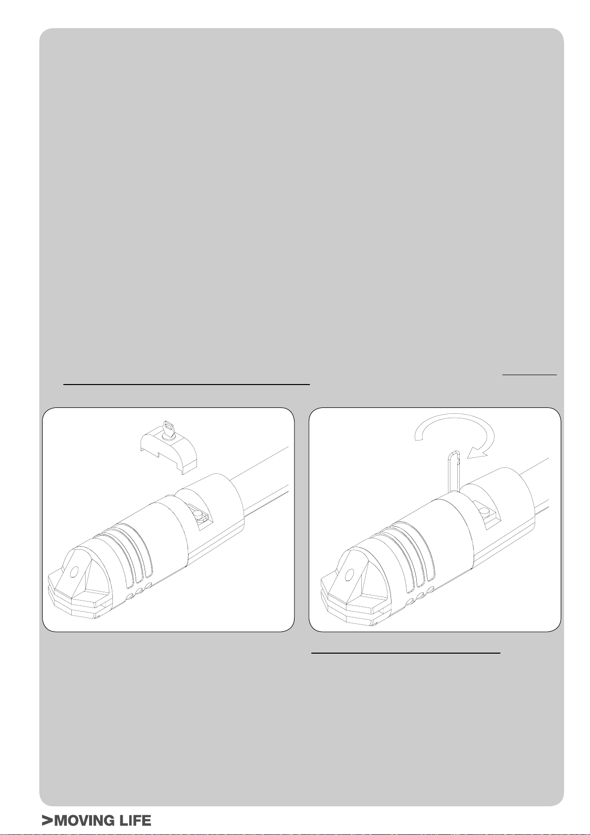
Español
INSTRUCCIONES Y ADVERTENCIAS DESTINADAS AL USUARIO DE L’AUTOMATISMO
¡FELICIT ACIONES por haber elegido un producto TAU para su automatización!
T au S.r .l. produce componentes para la automatización de cancelas, puertas, barreras, cerramientos, tales como: motorreductores, centrales de mando,
radiomandos, luces intermitentes, fotocélulas y accesorios.
Los productos Tau son fabricados sólo con materiales de calidad y excelentes mecanizados. Nuestra empresa busca constantemente soluciones
innovadoras que simplifi quen aún más el uso de nuestros aparatos, los que son cuidados bajo todo aspecto (técnico, estético y ergonómico): en la gran
gama Tau, su instalador puede escoger el producto que satisfaga de la mejor manera sus exigencias.
Tau no es quien escoge los componentes de su automatización, este es un trabajo de análisis, evaluación, elección de los materiales y realización de
la instalación efectuado por su instalador de confi anza.
Por lo tanto, cada automatización es única y sólo su instalador puede ejecutar una instalación a medida de sus exigencias (puesto que cuenta con la
experiencia y profesionalidad necesarias), segura y fi able en el tiempo y, sobre todo, que respete las normativas vigentes.
Una instalación de automatización es una gran comodidad, además de un sistema de seguridad válido y, con un mantenimiento reducido y sencillo,
está destinada a durar por mucho tiempo.
Aunque bien su automatización satisfaga el nivel de seguridad requerido por las normativas, esto no excluye la existencia de un “riesgo residual”, es
decir, la posibilidad de que se puedan crear situaciones de peligro causadas por un uso inconsciente o incorrecto. Por dicho motivo, a continuación le
damos algunos consejos sobre cómo comportarse para evitar inconvenientes:
- La primera vez que se usa: pida a su instalador que le explique el origen de los riesgos residuales y lea este manual de instrucciones y
advertencias para el usuario entregado por el instalador. Conserve el manual por cualquier problema que pueda surgir y recuerde entregarlo a un
posible nuevo dueño de la instalación.
- La instalación de automatización ejecuta fi elmente los mandos dados: un uso inconsciente o inadecuado puede ser peligroso. Por
consiguiente, no accione la automatización cuando en su radio de acción haya personas, animales o cosas.
- ¡NO ES UN JUGUETE! Trate de que los niños no jueguen cerca de la instalación y mantenga los controles remotos lejos de su alcance.
- Desperfectos: cada vez que la instalación no funcione correctamente, corte la alimentación eléctrica de la automatización y realice el desbloqueo
manual (como muestra la fi gura). No realice ninguna reparación y llame a su instalador: una vez desbloqueada, la instalación funcionará
manualmente como antes de montar la automatización.
- Mantenimiento: para garantizar una larga vida útil y para un funcionamiento seguro, la instalación, al igual que cualquier otra maquinaria, requiere
un mantenimiento periódico. Establezca con su instalador las frecuencias de dicho mantenimiento. Tau aconseja realizar un mantenimiento cada
6 meses para un uso residencial normal, que puede variar según la intensidad de uso (siempre cada 3000 ciclos de trabajo).
N.B. cualquier tipo de operación (control, mantenimiento o reparación) debe ser realizada sólo por personal cualifi cado.
- No modifi que la instalación ni los parámetros de programación y regulación: la responsabilidad es del instalador .
N.B.: el ensayo fi nal, los trabajos de mantenimiento periódico y las posibles reparaciones deben ser documentados (en los espacios
disponibles) por quien los efectúa y los documentos tienen que ser conservados por el dueño de la instalación (LA FALTA DE
DOCUMENT ACIÓN DETERMINA LA CADUCIDAD DE LA GARANTÍA).
- Desguace: al fi nal de la vida útil de la instalación, el desguace debe ser realizado por personal cualifi cado y los materiales deben ser reciclados o
eliminados según las normas locales vigentes.
Introduzca la llave en el desbloqueo y girarla en el sentido del reloj.
Tirar hacia arriba el tapón de plàstico, como en la fi gura.
La maniobra manual debe efectuarse SÓLO con la puerta detenida y DESPUÉS de haber cortado la alimentación a la central eléctrica.
Nota: si su instalación está dotada de un control remoto que, transcurrido un cierto período, no funciona correctamente o deja de funcionar,
podría ser que la pila esté agotada (dura desde varios meses a 2/3 años según el modelo). Ud. se podrá dar cuenta de este inconveniente por el
hecho de que la luz del indicador de confi rmación de la transmisión es débil, o bien se enciende sólo durante un breve instante. Antes de llamar
al instalador, pruebe sustituir la pila con una de otro transmisor que funcione correctamente: si el problema fuera este, sustituya la pila con otra
del mismo tipo.
Si Ud. deseara montar en su casa un nuevo tipo de automatización, contacte al mismo instalador y a Tau, así podrá tener la garantía de
un asesoramiento de un experto y los productos más modernos del mercado, el mejor funcionamiento y la máxima compatibilidad de las
automatizaciones.
Le agradecemos por haber leído estas recomendaciones y esperamos que esté satisfecho de su nueva instalación: ante cualquier exigencia,
contacte con confi anza a su instalador.
Tirar la palanca hacia arriba y girarla en el sentido del reloj.
Tras haber cerrado de nuevo el tapón de plástico, abra y cierre la
cancela manualmente.
P2000 Series
5
Page 22

Data
Date
Datum
Date
Fecha
Descrizione intervento
Description of job
Beschreibung des Eingriffs
Description intervention
Descripción del trabajo
Parti sostituite
Parts replaced
Ersetzte teile
Parties remplacées
Piezas sustituidas
Firma manutentore
Fitter’s signature
Unterschrift des
Wartungsmannes
Signature réparateur
Firma del técnico
Firma utilizzatore
User’s signature
Unterschrift des
Benutzers
Signature utilisateur
Firma del usuario
6
P2000 Series
Page 23

Data
Date
Datum
Date
Fecha
Descrizione intervento
Description of job
Beschreibung des Eingriffs
Description intervention
Descripción del trabajo
Parti sostituite
Parts replaced
Ersetzte teile
Parties remplacées
Piezas sustituidas
Firma manutentore
Fitter’s signature
Unterschrift des
Wartungsmannes
Signature réparateur
Firma del técnico
Firma utilizzatore
User’s signature
Unterschrift des
Benutzers
Signature utilisateur
Firma del usuario
P2000 Series
7
Page 24

Data
Date
Datum
Date
Fecha
Descrizione intervento
Description of job
Beschreibung des Eingriffs
Description intervention
Descripción del trabajo
Parti sostituite
Parts replaced
Ersetzte teile
Parties remplacées
Piezas sustituidas
Firma manutentore
Fitter’s signature
Unterschrift des
Wartungsmannes
Signature réparateur
Firma del técnico
Firma utilizzatore
User’s signature
Unterschrift des
Benutzers
Signature utilisateur
Firma del usuario
8
P2000 Series
Page 25

MATÉRIAUX POUR L’INSTALLATION (fi g.2)
1) Art. S-650P2000185: Patte de fi xation porte galvanisée.
2) Art.P-650/P2000/P2000B:Actionneur série P2000/P2000B.
3) Art.S-P2250SG190: Grande patte de fi xation zinguée.
4) Art.S-650P225050: Patte angulaire de fi xation zinguée.
ÉLÉMENTS DU VÉRIN (fi g.6)
SI LE PILIER EST EN MAÇONNERIE (fi g.7):
utiliser 3 chevilleS M10 pour fi xer la patte angulaire au mur ;
SI LE PILIER EST EN MÉTAL (fi g.7):
souder soigneusement la grande patte de fi xation au portail.
MESURES À RESPECTER (fi g.3, fi g.4 et fi g.5)
X° A B
90 140 ÷ 165 mm 145 mm 40 mm
90 140 ÷ 165 mm 150 mm 40 mm
90 140 ÷ 160 mm 155 mm 40 mm
90 140 ÷ 155 mm 160 mm 40 mm
90 140 ÷ 155 mm 165 mm 40 mm
90 140 ÷ 150 mm 170 mm 40 mm
90 140 ÷ 145 mm 175 mm 40 mm
90 140 ÷ 145 mm 180 mm 40 mm
90 140 mm 185 mm 40 mm
100 165 mm 145 mm 40 mm
100 165 mm 150 mm 40 mm
Epaisseur
du portail
• en utilisant la méthode mentionnée au point 2, orienter la
fourche vers les carters jusqu’à ce que l’étrier de fi xation du
vantail se superpose à la position que l’on vient de marquer sur
le vantail.
Si l’opération est possible, l’installation est correcte.
On peut utiliser cette méthode pour calculer où souder la petite
patte pour chaque angle d’ouverture (X°) désiré à condition que
cela soit possible (si les paramètres A et B et la course utile de
l’actionneur le permettent).
7_ fi xer l’étrier de fi xation du vantail dans la position marquée.
Note : pour une sécurité complète, il est obligatoire d’installer,
s’il n’y en a pas, les arrêts mécaniques (butées au sol) avec
bouchon en caoutchouc en ouverture et fermeture (3 fi g.13),
de manière qu’elles interviennent juste avant les fi ns de
course mécaniques du piston.
UTILISATION DU DÉBLOCAGE MANUEL
1 - Introduire la clé dans le dispositif de déblocage et la tourner
dans le sens des aiguilles d’une montre.
2 - Tirer vers le haut le bouchon en plastique comme sur la fi g.8.
3 - Tirer le levier vers le haut et le tourner dans le sens des aiguilles
d’une montre.
4 - Après avoir refermé le bouchon en plastique, manœuvrer
manuellement le portail en l’ouvrant et en le refermant.
N.B.: Effectuer les opérations décrites dans le sens inverse
pour rebloquer le portail (abaisser le levier précédemment
tourné et refermer le bouchon si l’on décide de laisser le
déblocage activé pour manœuvrer manuellement le portail).
FRANCAIS
X° A B
90 145 ÷ 170 mm 150 mm 50 mm
90 145 ÷ 165 mm 155 mm 50 mm
90 145 ÷ 160 mm 160 mm 50 mm
90 145 ÷ 160 mm 165 mm 50 mm
90 145 ÷ 155 mm 170 mm 50 mm
90 145 ÷ 150 mm 175 mm 50 mm
90 145 ÷ 150 mm 180 mm 50 mm
90 145 mm 185 mm 50 mm
100 170 mm 150 mm 50 mm
÷ = INTERVALLE ENTRE LA VALEUR MINIMUM ET LA
VALEUR MAXIMUM ADMISES.
Course utile = 350 mm
Dans le cas où les dimensions du pilier ou la position du gond ne
permettent pas d’avoir la cote B dans la mesure voulue, il faut
impérativement réaliser une niche sur le pilier comme indiqué
fi g.5.
Epaisseur
du portail
INSTALLATION
Respecter les valeurs du tableau et huiler les gonds du portail.
1_ Fixer l’actionneur à la grande patte (ou patte angulaire) en
utilisant la vis fournie (voir 1 fi g.7) ;
2_ vérifi er la mesure de 690 mm (fi g.4 - normalement, le vérin
est fourni préréglé, éventuellement, si la mesure est inférieure,
mettre le fi n de course mécanique - 27 fi g.16-17 - en butée
contre le bouchon terminal puis, en agissant sur les goujons
de fi xation et en connectant momentanément le moteur à une
batterie pour la version à 12 V ou à un clavier de commande
pour la version à 230 V - mettre la fourche en butée sur le fi n
de course mécanique) ;
3_ fi xer l’étrier de fi xation du vantail à la fourche ;
4_ appuyer l’étrier que l’on vient de fi xer contre le vantail du portail
complètement fermé et marquer les points de fi xation (en
veillant à la planéité, voir fi g. 3).
Avant de passer à la phase successive, effectuer l’essai suivant:
ouvrir manuellement le portail jusqu’à l’angle maximum désiré ;
•
BRANCHEMENT ÉLECTRIQUE AU MOTEUR
Enlever les 4 vis de fi xation et soulever le couvercle plastique
comme sur la fi g.9.
MODELE P2000BENC
Connecter le câble multipolaire* aux bornes de la fi g.10, en
considérant que :
câble rouge sect. 2.5 mm² : phase moteur ;
cablr bleu sect. 2.5 mm² : neutre moteur ;
câble brun sect. 0.5 mm² : positif encodeur ;
câble bleu sect. 0.5 mm² : négatif encodeur ;
câble blanc sect. 0.5 mm² : signal encodeur.
Utiliser esxclusivement des logiques de commande munies
d’embrayage électrique ;
* Nous conseillons d’utiliser le cable composé TAU srl, code M-
03000010CO.
MODELE P2000
1 - Effectuer la connexion à la borne de la fi g.11 avec des câbles
d’une section d’au moins 1.5 mm² en essayant le sens de
rotation du moteur et en se souvenant que :
câble jaune-vert: masse ;
câble bleu: commun ;
câble noir: phase ;
câble brun: phase.
2 - À proximité de la carte électronique de commande, connecter
le condenseur fourni en parallèle aux deux phases du moteur
en veillant à ne pas court-circuiter les deux fi ls afi n d’éviter tout
risque de décharge due à des courants résiduels. N’utiliser que
des logiques de commande avec embrayage électrique.
RECOMMANDATIONS DE CARACTÈRE GÉNÉRAL
Assurer la sécurité du portail conformément aux dispositions
prescrites par les normes en vigueur.
Choisir des parcours brefs pour les câbles et séparer les câbles de
puissance des câbles de commande.
Pour la mise au point du couple maximum du motoréducteur,
suivre les normes en vigueur.
Conformément à la norme européenne en matière de sécurité, il est
conseillé d’insérer un interrupteur automatique magnétothermique
avec In=6A pour pouvoir couper l’alimentation en cas d’intervention
de maintenance sur le portail.
P2000 Series
17
Page 26

Vérifi er que tous les dispositifs installés fonctionnent correcte-
ment.
Placer des panonceaux bien lisibles qui informent de la présence
du portail motorisé.
EMPLOI
Il est formellement interdit d’utiliser l’appareil pour des buts
différents ou dans des circonstances différentes de celles
qui sont mentionnées ici. Normalement, la logique électronique
installée (qui doit avoir l’embrayage électrique incorporé)
permet de sélectionner le fonctionnement:
automatique : une impulsion de commande effectue l’ouverture et
la fermeture du portail;
semi-automatique : une impulsion de commande effectue
l’ouverture ou la fermeture du portail;
En cas de coupure de courant électrique, le portal peut fonctionner
grâce à la possibilité de gestion manuelle, pour laquelle il faut agir
sur le dispositif de “débrayage manuel”. Le modèle P2000BENC,
alimentable par batterie tampon, est en mesure d’effectuer au
moins 15 cycles complets (ouverture et fermeture) de manière
autonome.
Nous rappelons que nous sommes en présence d’un dispositif
automatique alimenté par le courant électrique; il faut donc prendre
toutes les précautions de rigueur. En particulier, faire attention à:
• ne pas toucher l’appareil avec les mains mouillées et/ou avec
les pieds mouillés ou nus;
• couper le courant avant d’ouvrir le boîtier des commandes et/
ou l’actionneur;
• ne pas tirer le cordon d’alimentation pour débrancher la prise
FRANCAIS
de courant;
• ne pas toucher le moteur si l’on n’est pas sûr qu’il est refroidi
• mettre en mouvement le portail seulement quand il est
complètement visible;
• rester hors du rayon d’action du portail tant qu’il est en
mouvement: attendre qu’il soit complètement arrêté;
• ne pas laisser les enfants ou les animaux jouer à proximité du
portail;
• ne pas laisser des enfants ou des incapables manipuler la
télécommande ou d’autres dispositifs d’actionnement;
• effectuer la maintenance périodique;
• en cas de panne, couper l’alimentation, ouvrir et fermer
manuellement le portail seulement si cette opération est
possible et sûre. Eviter toute intervention et faire appel à un
technicien agréé.
MAINTENANCE
Les actionneurs P2000 et P2000BENC ont besoin de peu
d’entretien. Toutefois, leur bon fonctionnement dépend également
de l’état du portail; par conséquent, nous décrirons brièvement
également les opérations à accomplir pour avoir toujours un portail
en bon état.
ATTENTION : personne, à l’exception de la personne chargée
de la maintenance qui doit être un technicien spécialisé, doit
pouvoir commander l’automatisme pendant la maintenance.
Nous recommandons par conséquent de couper l’alimentation de
secteur, évitant ainsi le risque de chocs électriques. Si par contre
l’alimentation doit être présente pour certains contrôles, nous
recommandons de contrôler ou de désactiver tout dispositif de
commande (émetteurs, tableaux de commande, etc.) à l’exception
de celui qui est commandé par la personne chargée de la
maintenance.
Maintenance ordinaire
Chacune des opérations suivantes doit être effectuée quand le
besoin s’en fait sentir et dans tous les cas tous les 6 mois pour un
usage domestique (environ 3000 cycles de travail) et tous les 2
mois pour un usage intensif, par ex. usage collectif (toujours tous
les 3000 cycles de travail).
Portail :
- lubrifi er et graisser les gonds du portail.
Automatisme :
- vérifi cation du fonctionnement des dispositifs de sécurité
(cellules photoélectriques, barre palpeuse etc.) en respectant
les fréquences et en suivant les modalités indiquées par les
constructeurs;
- graisser (avec un graisseur) la vis sans fi n accessible par la
partie inférieure du vérin (voir fi g.12); nous conseillons d’utiliser
de la graisse au savon de lithium complexe de la marque
SYNECO.
- vérifi er l’état de charge de la batterie avec un testeur pour
batteries au plomb-acide; en cas de remplacement, utiliser
une batterie originale et recycler l’unité déchargée selon
la réglementation en vigueur (en alternative TAU conseille
d’utiliser des batteries FIAMM).
Maintenance extraordinaires et rupture
Si des interventions d’une certaine entité devaient se rendre
nécessaire sur des parties électromécaniques, nous conseillons
d’enlever le composant concerné par la panne pour permettre
une réparation en atelier par les techniciens de la maison mère ou
agréés par cette dernière.
NOTE : Nous conseillons de conserver toute la documentation
relative à l’installation à l’intérieur de l’armoire de
commande ou à proximité immédiate.
INSTALLATION TYPE (fi g.13)
APPENDICE
QUELS ESP ACES DE SÉCURITÉ DOIS-JE RESPECTER POUR
L’AUTOMATISATION D’UN PORTAIL?
• La distance A fi g.14 entre le jambage et le montant adjacent
du portail doit être constante durant la rotation du portail. Si la
distance est variable, la distance doit être ≥ 25 mm sur toute la
hauteur; si ce n’est pas le cas, il faut protéger l’espace rendu
ainsi accessible sur toute la hauteur du portail jusqu’à une
limite maximum de 2,5 m.
• La distance B fi g.14 entre le sol et le portail doit être ≥ 50 mm,
si à cause de la pente du terrain la distance B est variable,
l’installateur devra prendre les mesures qu’il jugera les plus
adaptées pour réduire le risque.
• Dans un portail à deux battants, la distance C fi g.15 entre les
deux battants fermés doit être ≥ 2,5 cm; cet espace peut être
recouvert en installant une barre palpeuse sur le bord d’un
battant ou en plaçant un élément élastique déformable dans
l’espace libre. En alternative, cet espace peut être inférieur
ou nul mais il faut réaliser un décalage entre les battants en
fermeture de manière à créer un espace D fi g.15 de 50 cm.
CONSEILS POUR UNE INSTALLATION SÛRE
Fonctionnement avec homme présent: il suffi t d’un arrêt
d’urgence et d’un clignotant
Fonctionnement automatique ou semi-automatique: il faut
installer un clignotant et régler le couple du moteur suivant la
description donnée plus loin; si ce réglage n’est pas possible, il
faut installer une barre palpeuse.
• appliquer deux photocellules, une à l’extérieur et une à l’intérieur
de la voie de passage pour délimiter la zone de mouvement
du portail. En cas de superposition des battants au niveau du
profi l de butée, il est obligatoire de les décaler (distance D fi g.
15).
Pour tous les types de fonctionnement: Si en ouverture, le
battant s’arrête par rapport à un obstacle fi xe (muret, mur, pilier,
etc.) à une distance inférieure à 40 cm (E fi g.15), il faut appliquer
sur le battant ou sur la partie fi xe une barre palpeuse en respectant
les critères suivants:
1 - s’il s’agit d’un obstacle qui se développe principalement en
hauteur (c’est-à-dire à la verticale) la barre palpeuse s’applique
(sur toute la longueur de l’obstacle par conséquent la condition
ci-dessus est valable) à une hauteur comprise entre 40 et 60
cm par rapport au sol;
18
P2000 Series
Page 27

2 - s’il s’agit d’un obstacle qui se développe principalement
à l’horizontale et d’une hauteur inférieure à 60 cm, la barre
palpeuse s’applique à 5 cm du bord supérieur de l’obstacle.
CARACTÉRISTIQUES, RÉGLAGES ET INSTALLATION
DES DISPOSITIFS DE SÉCURITÉ
Photocellules
• Elles doivent être placées à une hauteur variable entre 40 et 60
cm par rapport au sol et à une distance max. de 10 cm calculée
par rapport au bord du battant ouvert et au portail fermé.
Barre palpeuse
• Dans le cas le plus simple prévu, il doit y avoir des contacts
Normalement Fermés NF;
• La course élastique ou déformation minimum doit être
supérieure d’au moins 1 cm par rapport à l’espace d’arrêt du
portail à partir du moment où le dispositif intervient.
Limiteur de couple
• Il doit être réglé de manière que le battant s’arrête en présence
d’une résistance mécanique de 150 N (environ 15 Kg ) mesurés
sur le bord du battant, à condition que son énergie cinétique ne
dépasse pas 10 J.
FRANCAIS
P2000 Series
19
Page 28

MATERIALES PARA LA INSTALACIÓN (fi g.2)
1) Art.S-650P200185: Estribo galvanizado de fi jación de la hoja.
2) Art.P-650/P2000/P2000B: Accionador serie P2000/P2000B
3) Art.S-P2250SG190: Estribo grande galvanizado
4) Art.S-650P225050: Estribo angular galvanizado
ELEMENTOS DEL ACTUADOR (fi g.6)
SI EL PILAR ES DE MAMPOSTERÍA (fi g.7):
emplee 3 tornillos M10 para sujetar el estribo angular a la pared;
SI EL PILAR ES DE METAL (fi g.7):
soldar perfectamente la brida grande en la verja.
MEDIDAS A RESPETAR (fi g.3, fi g.4 y fi g.5)
X° A B
90 140 ÷ 165 mm 145 mm 40 mm
90 140 ÷ 165 mm 150 mm 40 mm
90 140 ÷ 160 mm 155 mm 40 mm
90 140 ÷ 155 mm 160 mm 40 mm
90 140 ÷ 155 mm 165 mm 40 mm
90 140 ÷ 150 mm 170 mm 40 mm
90 140 ÷ 145 mm 175 mm 40 mm
90 140 ÷ 145 mm 180 mm 40 mm
90 140 mm 185 mm 40 mm
100 165 mm 145 mm 40 mm
100 165 mm 150 mm 40 mm
X° A B
90 145 ÷ 170 mm 150 mm 50 mm
90 145 ÷ 165 mm 155 mm 50 mm
90 145 ÷ 160 mm 160 mm 50 mm
ESPAÑOL
90 145 ÷ 160 mm 165 mm 50 mm
90 145 ÷ 155 mm 170 mm 50 mm
90 145 ÷ 150 mm 175 mm 50 mm
90 145 ÷ 150 mm 180 mm 50 mm
90 145 mm 185 mm 50 mm
100 170 mm 150 mm 50 mm
Espesor
de la cancela
Espesor
de la cancela
abrazadera de enganche de la hoja pueda sobreponerse a la
posición que se acaba de marcar en la hoja.
Si esta operación se puede realizar, signifi ca que la instalación es
correcta.
Es posible llevar a cabo este método a fi n de establecer dónde
hay que soldar la brida pequeña por cada ángulo de abertura (X°)
deseado, siempre y cuando sea posible (o sea, con los parámetros
A y B y la carrera útil del accionador justos).
5_ fi je la abrazadera de enganche de la hoja en la posición
marcada.
Nota: para mayor seguridad es obligatorio instalar, si no se
encuentran ya presentes, los topes mecánicos (batientes de
pavimento) con tapón de goma en
la cancela (3 fi g.13),
antes de los topes del pistón.
de forma que intervengan unos momenos
la apertura y en el cierre de
UTILIZACIÓN DEL DESBLOQUEO MANUAL
1 - Introduzca la llave en el desbloqueo y gírela hacia la derecha.
2 - Tire hacia arriba el tapón de plástico, como muestra la fi g.8.
3 - Tire hacia arriba de la palanca y gírela hacia la derecha.
4 - T ras haber cerrado de nuevo el tapón de plástico, abra y cierre
la cancela manualmente.
N.B.: efectúe las operaciones descritas en el sentido inverso
para volver a bloquear la cancela (baje la palanca que antes
girara y cierre el tapón si decide dejar el desbloqueo activo
para mover la cancela a mano).
CONEXION ELECTRICA AL MOTOR
Quite los 4 tornillos de fi jación y levante la tapa de plástico, como
muestra la fi g.9.
MODELO P2000BENC
Conecte el cable multipolar* a los bornes de fi g.10, recordando
que :
Cable rojo sec. 2.5 mm²: fase motor
Cable azul sec. 2.5 mm²: neutro motor
Cable marròn sec. 0.5 mm²: positivo encoder
Cable azul sec. 0.5 mm²: negativo encoder
Cable blanco: señal encoder
Use exclusivamente centralitas con embraque eléctrico.
* Le aconsejamos que utilice el cable compuesto de TAU srl, cód.
M-03000010CO.
÷ = INTERVALO ENTRE EL VALOR MÍNIMO Y EL VALOR
MÁXIMO CONSENTIDOS
Carrera útil = 350 mm
En el caso de que las dimensiones de la columna o la posición de
la bisagra no permitan dar a la cota “B” el valor deseado, hará
falta hacer un nicho en la columna, como se indica en la fi g.5.
INSTALACIÓN
Respetar los valores de la tabla y engrasar los goznes de la verja.
1_ Sujetar el accionador a la brida grande (o placa angular)
mediante el tornillo en equipamiento (ver 1 fi g.7);
2_ compruebe la medida de 690 mm (fi g.4 - normalmente el
actuador se suministra ya preparado, pero si eventualmente la
medida fuera inferior, coloque el fi nal de carrera mecánico - 27
fi g.16-17 – en contacto con el tapón terminal accionando los
bulones de centraje de fi jación y , conectando temporáneamente
el motor a una batería para la versión de 12V o a un panel
de mandos para la versión de 230V, coloque la horquilla en
contacto con el fi n de carrera mecánico);
3_ fi je la abrazadera de enganche de la hoja a la horquilla;
4_ apoye la abrazadera que se acaba de fi jar a la hoja de la
cancela completamente cerrada y señale los puntos de fi jación
(controlando que sea plano, véase fi g.3).
Antes de pasar a la fase sucesiva, hay que comprobar lo
siguiente:
• abra manualmente la cancela hasta el ángulo máximo
deseado;
• utilizando el mismo método que se menciona en el punto 2,
coloque la horquilla en dirección de las cápsulas hasta que la
MODELO P2000
1 - Realice la conexión al borne de la fi g.11 con cables que tengan
una sección de al menos 1,5 mm² , comprobando el sentido de
rotación del motor y recordando que:
cable amarillo-verde: tierra;
cable azul: común;
cable negro: fase;
cable marrón: fase.
2 - Conecte, cerca de la tarjeta electrónica de control, el
condensador que se entrega con el equipamiento de base en
paralelo a las 2 fases del motor, sin cortocircuitar los dos cables
para evitar posibles descargas debidas a corrientes residuales.
Utilice exclusivamente centrales con embrague eléctrico.
RECOMENDACIONES DE CARACTER GENERAL
Integre el sistema de seguridad de la cancela de acuerdo con las
normas vigentes.
Elija recorridos breves para los cables y mantenga separados los
cables de potencia de aquellos de mando.
Para la puesta a punto del par máximo del motorreductor, respete
la normativa en vigor.
De acuerdo con la normativa europea en materia de seguridad,
se aconseja montar, antes de la instalación, un interruptor
magnetotérmico con In=6 A para poder cortar la alimentación
cuando se deban realizar trabajos de mantenimiento.
Compruebe que cada uno de los dispositivos instalados funcione
correctamente y que sea efi caz.
Coloque carteles fáciles de leer que informen que hay una cancela
motorizada.
20
P2000 Series
Page 29

USO
Está prohibido utilizar este aparato para otros usos diferentes
o en circunstancias distintas de aquellas aquí indicadas.
Normalmente la centralita electrónica instalada (que debe estar
equipada con embrague eléctrico) permite seleccionar el
funcionamiento:
automático: un impulso de mando abre y cierra la cancela.
semiautomático: un impulso de mando abre y cierra la cancela.
Si falta la energía eléctrica, la cancela puede funcionar gracias
a la posibilidad de empleo manual; en tal caso es necesario
actuar sobre el dispositivo de desbloqueo manual. El modelo
P20000BENC, que se puede alimentar con batería compensadora,
puede efectuar por lo menos 15 ciclos completos (apertura y cierre)
de modo autónomo.
Le recordamos que nos hallamos ante un dispositivo automático
alimentado por corriente eléctrica, por lo tanto, se lo debe usar con
precaución. En particular se recomienda:
• No tocar el aparato con la manos mojadas o con los pies
mojados o descalzos.
• Desconectar la corriente antes de abrir la caja de mandos o el
accionador .
• No tirar del cable de alimentación para desconectar la clavija.
• No tocar el motor si no está seguro de que se haya enfriado
completamente.
• Accionar la cancela sólo cuando esté completamente a la
vista.
• Mantenerse fuera del radio de acción de la cancela si ésta se
está moviendo, esperar a que se haya detenido.
• No dejar que niños o animales jueguen cerca de la cancela.
• No dejar que niños o personas incapacitadas usen el control
remoto u otros dispositivos de accionamiento.
• Realizar el mantenimiento periódico.
• Ante una avería, cortar la corriente y mover la cancela
manualmente sólo si es posible y seguro. No realizar ningún
tipo de reparación y llamar a un técnico autorizado.
MANTENIMIENTO
Los accionadores P2000 y P2000BENC necesitan poco
mantenimiento; su funcionamiento correcto depende de las
condiciones de la cancela: por tal razón describiremos a
continuación, concisamente, los trabajos que se han de llevar a
cabo para disponer de una cancela siempre efi ciente.
ATENCIÓN: ninguna persona, salvo el técnico encargado del
mantenimiento, que debe ser un técnico especializado, debe
poder accionar la automatización durante el mantenimiento.
Por lo tanto, se recomienda cortar la alimentación de red, así
evitando el peligro de sacudidas eléctricas. En cambio, si fuera
necesario mantener la alimentación conectada, se recomienda
controlar o desactivar todos los dispositivos de mando (control
remoto, botonera, etc.) salvo el dispositivo usado por el técnico
del mantenimiento.
Mantenimiento ordinario
Cada una de las siguientes operaciones debe llevarse a cabo
cuando se advierta que es necesario y, de todas maneras, cada
6 meses para uso doméstico (alreador de 3000 ciclos de trabajo)
y cada 2 meses para uso intensivo, por ej.: comunitario (siempre
cada 3000 ciclos de trabajo).
Cancela:
- lubrique y engrase los goznes de la cancela.
Instalación de automatización:
- controle el funcionamiento correcto de los dispositivos de
seguridad (fotocélulas, banda neumática, etc.), según los
intervalos de tiempo y criterios indicados por los proveedores;
- engrase (con engrasador) el tornillo sin fi n al que se accede
desde la parte inferior del accionador (véase fi g.12); le
aconsejamos que utilice la grasa de jabón de litio complejo de
SYNECO.
- controle la carga de la batería con un tester para baterías
plomo-ácido; de ser necesaria su sustitución, utilice una
batería original y recicle aquella descargada conforme a las
disposiciones vigentes (como alternativa TAU le aconseja que
utilice baterías FIAMM).
Mantenimiento extraordinario o roturas
Si fuera necesario realizar reparaciones importantes de piezas
electromecánicas, se recomienda desmontar el componente
averiado para poderlo reparar en los talleres por los técnicos del
fabricante o por él autorizados.
NOTA: Se aconseja guardar toda la documentación de la
instalación en el interior o cerca de la central.
INSTALACIÓN TIPO (fi g.13)
APÉNDICE
CUÁLES SON LOS ESPACIOS DE SEGURIDAD QUE DEBO
RESPETAR CUANDO SE AUTOMATIZA UNA CANCELA?
• La distancia A fi g.14 entre el marco y el larguero adyacente
de la cancela debe ser constante durante la rotación de la
cancela. Si la distancia es variable, la distancia debe ser ≥ 25
mm a todo lo alto; si así no fuera, hay que aislar el espacio que
así será accesible a todo lo alto de la cancela, hasta un límite
máximo de 2,5 m.
• La distancia B de fi g.14 entre piso y hoja debe ser ≥ 50 mm, si
a causa de la pendiente del piso la distancia B es variable, el
instalador puede adoptar libremente las medidas que considere
oportunas para reducir el peligro de enganche.
• En una cancela de dos hojas, la distancia C fi g.15 entre las dos
hojas cerradas, debe ser ≥ 2,5 cm como mínimo; dicho espacio
se puede cubrir instalando una banda neumática en el borde
de una hoja o colocando un elemento elástico deformable en
el espacio libre. Como alternativa, dicho espacio puede ser
menor o no existir, pero hay que realizar un desfasamiento
entre las hojas en el cierre, de manera que se cree un espacio
D fi g.15 de 50 cm.
CONSEJOS PARA UNA INSTALACIÓN SEGURA
Funcionamiento hombre muerto: basta una parada de
emergencia y una luz intermitente
Funcionamiento automático o semiautomático: hay que instalar
una luz intermitente y regular el par del motor tal como indicado
más adelante; si tal regulación no fuera posible, hay que instalar
una banda neumática.
• aplique dos fotocélulas, una afuera y una adentro del área de
tránsito para delimitar la zona de movimiento de la cancela.
Si las hojas se superponen en un perfi l de contacto hay que
descentrar las hojas como antedicho (distancia D fi g.15).
Para todo tipo de funcionamiento: si durante la apertura la hoja
se detiene respecto de un obstáculo fi jo (tabique, pared, pilar,
etc.) a una distancia (E fi g.15) menor que 40 cm, hay que aplicar
sobre la hoja o sobre la parte fi ja una banda neumática según los
siguientes criterios:
1 - si se trata de un obstáculo que se desarrolla principalmente a
lo alto (es decir en vertical) la banda se aplica (sobre toda la
altura del obstáculo, por lo que es válida la condición susodicha)
a una altura comprendida entre 40 y 60 cm desde el piso;
2 - si se trata de un obstáculo que se desarrolla principalmente en
horizontal y a altura menor que 60 cm, la banda se aplica a 5
cm del borde superior del obstáculo.
CARACTERÍSTICAS, REGULACIONES E INSTALACIÓN
DE LOS DISPOSITIVOS DE SEGURIDAD
Fotocélulas :
• Se colocan a una altura que varía entre 40 y 60 cm del piso y
a una distancia máx. de 10 cm calculada desde el borde de la
hoja abierta y al ras de la cancela cerrada.
Banda sensible de seguridad
• En el caso más sencillo previsto deben ser contactos
Normalmente Cerrados NC;
• La carrera elástica o deformación mínima debe ser mayor
que 1 cm como mínimo respecto del espacio de parada de la
cancela desde el momento de activación del dispositivo
Limitador de par
• Se debe regular de modo que la hoja se detenga ante la
presencia de una resistencia mecánica de 150 N (alrededor de
15 kg) medidos en el borde, siempre que la energía cinética de
la hoja no supere 10 J.
ESPAÑOL
P2000 Series
21
Page 30

14_ ESPLOSI DELLA SERIE P2000 \ EXPLOSIONSZEICHNUNGEN DER REIHE P2000 \ EXPLODED DIAGRAMS OF
THE P2000 SERIES \ VUES ÉCLATÉES DE LA SÉRIE P2000 \ DESPIECES DE LA SERIE P2000
P2000 - 230 V a.c.
RIF. DESCRIZIONE ART. Q.TÁ
1 Alberino per gruppo sblocco S-650P200016 1
2 Cuscinetto naz. stagno 6201 2RS M-010NG06201 1
3 Coppia conica R 1:1 z16 M.3 lavorata M-ING0000CC1 1
4 Chiavetta 6x6x25 M-V600060625 1
5 Anello seeger E15 M-V700E00015 2
6 Distanziale per gruppo sblocco P2000 S-650P200017 1
7 Ingranaggio bronzo Z24 M.1,25 sblocco S-650P200018 1
8 Boccola acciaio autol. a secco TFF15090 S-P225000080 1
9 Molla a compressione D.8x1, 1xP.4xLL41 M-0600000010 1
10 Perno sblocco D.8x30 zincato S-P225000040 1
11 Calotta post. mot. P2000 M-FSA0000410 1
12 Cuscinetto SKF schermato 6200 2Z/C3 M-010Z006200 1
13 Statore 73x38 H100 24C B 6P V230/50 S-650P200020 1
14 Albero motore 220V con rotore calett. M-ALB00P2000 1
15 Cuscinetto SKF stagno 6202 2RS/C3 M-010G006202 1
16 Calotta ant. mot. P2000 M-FSA0000400 1
17 Vite TSEI M6x16 zincata M-V450006016 1
18 Rondella di tenuta svasata 7,4x25x2,5 zincata S-650P200100 1
19 Cuscinetto naz. schermato 6203 2Z M-010NZ06203 2
20 Distanziale cuscinetti zincato S-P225000110 1
21 Vite P.20 5 principi 20x485 (P2000) M-ING0100P16 1
22 Tappo terminale per vite 5P. P2000 S-650P200130 1
23 Boccola madrevite D.20x5 P.20 P2000 S-650P200060 1
24 Forcella con boccola madrevite S-650P200B60 1
25 Dado E. autobloccante M12 basso M-V350AM12B0 1
26 Collare di fermo acciaio D.20/32 zincato S-650P200170 1
27 Grano a punta 6x5 zincato M-V999006005 2
28 Stelo in alluminio S-650P200140 1
29 Tappo in plastica grande per profi lo P2000 S-650P200135 1
30 Vite autoforante TC+ 3,5x13 inox M-V260TC3513I 2
31 Guscio inf. all. attuatore verniciato S-650P000010 1
32 Guscio sup. all. attuatore verniciato S-650P000000 1
33 Leva sblocco in
34 Anello OR 2050 M-025OR02050 1
35 Perno per eccentrico S-P225000070 1
36 Vite TCEI M8x35 fi letto mm.15 inox M-V400008035I 1
37 Cond. 10µf 7G75100L44-AC1 M-0300000040 1
38 Morsetto mamut OK 433/X PLP-NR M-0300000010 3
39 Vite trilobata TCB-D.10 6x30 torx. Z.G. M-V1100T6030 6
40 Capicorda occhiello CEM RF M5 M-0300000539 1
41 Coprimorsettiera S-P225000170 1
42 Vite autofi lettante TSP+ 3,5x13 inox M-V200TSP313I 4
43 Gruppo sblocco attuatori con chiave S-650P225010 1
44 Rosetta piana D.5x16 inox M-V500005015I 1
45 Vite autofi lettante TC+ 4,8x9,5 inox M-V250TC4895 1
fi lo S-P225000090 1
22
P2000 Series
Page 31
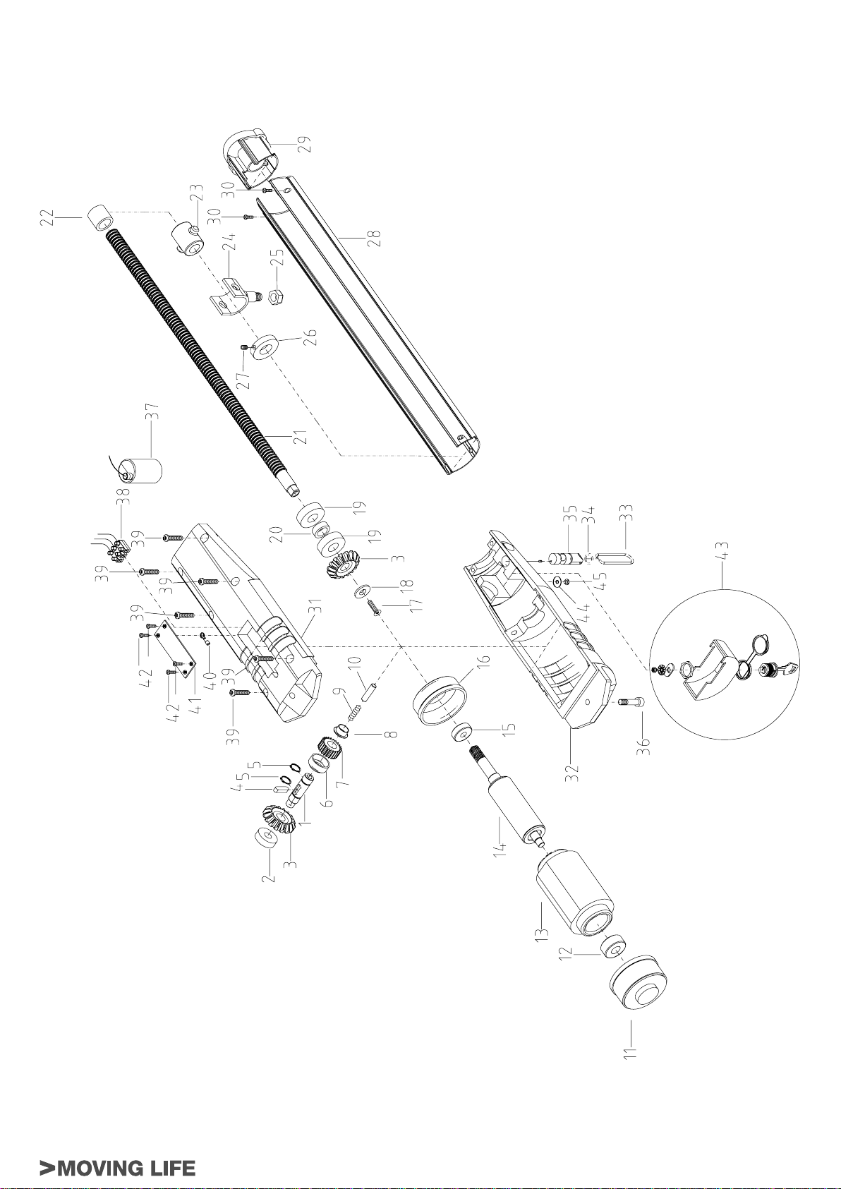
P2000 - 230 V a.c.
fi g. 16
P2000 Series
23
Page 32

P2000BENC - 12 V d.c.
RIF. DESCRIZIONE ART. Q.TÁ
1 Alberino per gruppo sblocco P2000 S-650P200016 1
2 Cuscinetto naz. stagno 6201 2RS M-010NG06201 1
3 Coppia conica R 1:1 z16 M.3 lavorata M-ING0000CC1 1
4 Chiavetta 6x6x25 M-V600060625 1
5 Anello seeger E15 M-V700E00015 2
6 Distanziale per gruppo sblocco P2000 S-650P200017 1
7 Ingranaggio bronzo Z24 M.1,25 sblocco S-650P200018 1
8 Boccola acciaio autol. a secco TFF15090 S-P225000080 1
9 Molla a compressione D.8x1, 1xP.4xLL41 M-0600000010 1
10 Perno sblocco D.8x30 zincato S-P225000040 1
11 Encoder fotodiodo P-250ENCD 1
12 Vite autofi lettante TC+ 3.5x6.5 M-V250TC3565 2
13 Tubetto Vipla D.4mm M-0300002204 0.065 mt.
14 Vite TSEI M4x25 zincata M-V450004025 1
15 Disco encoder P-250DE 1
16 Motore 12V cc 1200rpm 50W S-P2000B0000 1
17 Vite TSEI M6x16 zincata M-V450006016 1
18 Rondella di tenuta svasata 7.4x25x2.5 zincata S-650P200100 1
19 Cuscinetto naz. schermato 6203 2Z M-010NZ06203 2
20 Distanziale cuscinetti zincato S-P225000110 1
21 Vite P.20 5 principi 20x485 (P2000) M-ING0100P16 1
22 Tappo terminale per vite 5P. P2000 S-650P200130 1
23 Boccola madrevite D.20x5 P.20 P2000 S-650P200060 1
24 Forcella con boccola madrevite S-650P200B60 1
25 Dado E. autobloccante M12 basso M-V350AM12B0 1
26 Collare di fermo acciaio D.20/32 zincato S-650P200170 1
27 Grano a punta 6x5 zincato M-V999006005 2
28 Stelo in alluminio S-650P200140 1
29 Tappo in plastica grande per profi lo P2000 S-650P200135 1
30 Vite autoforante TC+ 3.5x13 inox M-V260TC3513I 2
31 Guscio inf. all. attuatore verniciato S-650P000010 1
32 Guscio sup. all. attuatore verniciato S-650P000000
33 Leva sblocco in fi lo S-P225000090 1
34 Anello OR 2050 M-025OR02050 1
35 Perno per eccentrico S-P225000070 1
36 Vite TCEI M8x35 fi letto mm.15 inox M-V400008035I 1
37 Morsetto mamut OK 433/X PLP-NR M-0300000010 5
38 Vite trilobata TCB-D.10 6x30 torx. Z.G. M-V1100T6030 6
39 Coprimorsettiera S-P225000170 1
40 Vite autofi lettante TSP+ 3,5x13 inox M-V200TSP313I 4
41 Gruppo sblocco attuatori con chiave S-650P225010 1
42 Rosetta piana D.5x16 inox M-V500005015I 1
43 Vite autofi lettante TC+ 4,8x9,5 inox M-V250TC4895 1
1
24
P2000 Series
Page 33

P2000BENC - 12 V d.c.
fi g. 17
P2000 Series
25
Page 34

DICHIARAZIONE DI CONFORMITA’ DECLARATION OF CONFORMITY KONFORMITÄTSERKLÄRUNG
(ai sensi della Direttiva Europea UE89/392 AlI. II.A) (European Directive 89/392 All. Il.A) (gemäß der Europäischen Richtlinie UE89/392
Anl. Il.A)
DECLARATlON DE CONFORMITÉ DECLARACIÓN DE CONFORMIDAD
(selon les termes de la Directive européenne UE89/392 All. II.A) (según la Directiva Europea UE89/392 Anex. Il.A)
Fabbricante / Manufacturer / Hersteller / Fabricant / Fabricante: TAU s.r.l.
Indirizzo / Address / Adresse / Adresse / Dirección: Via E. Fermi, 43
36066 - Sandrigo
VICENZA - ITALY
- Dichiara sotto la propria responsabilità che i prodottI:
- Declares under its own responsibility that the following products:
- Erklärt auf eigene Verantwortung, daß die Produkte:
- Déclare sous sa propre responsabilté que les produits:
- Declara, bajo su propria responsabilidad, que los productos:
650P2000 - 650P2000BENC
- Sono stati realizzati per essere incorporati in una macchina o per essere assemblati con altri dispositivi per costruire una
macchina considerata dalla DIRETTIVA MACCHINE 98/37/CE.
- Have been designed to be built into machinery or to be assembled with other devices so as to form machinery covered
by MACHINE DIRECTIVE 98/37/EC.
- zum Einbau in eine Maschine oder zur Zusammenfügung mit anderen Vorrichtungen zum Bau einer von der
Maschinenrichtlinie 98/37/EG in Betracht gezogenen Maschine verwirklicht wurde.
- Ils sont réalisés pour être incorporé dans une machine ou pour être assemblé avec d’autres dispositifs pour construire
une machine considérée par la Directive Machines 98/37/CE.
- han sido realizados para su incorporación en una máquina o para ser ensamblados con otros dispositivos, para constituir
así una máquina como lo considera la Directiva Máquinas 98/37/CE.
- Sono conformi ai requisiti essenziali di sicurezza delle direttive:
- Comply with the main safety requirements of the follwing Directives:
- daß er den wesentlichen Sicherheitsbedingungen folgender Richtlinien entspricht:
- Ils sont conformes aux conditions essentielles de sécurité des Directives:
- cumple con lo requisitos de seguridad de las siguientes directivas:
BASSA TENSIONE / LOW VOLTAGE / NIEDERSPANNUNG / BASSE TENSION / BAJA TENSION
73/23/CEE, 93/68/CEE
COMPATIBILITÀ ELETTROMAGNETICA / ELECTROMAGNETIC COMPATIBILITY / ELEKTROMAGNETISCHE
KOMPATIBILITÄT / COMPATIBILITÉ ÉLECTROMAGNÉTIQUE / COMPATIBILIDAD ELECTROMAGNETICA
89/336/CEE, 92/31/CEE, 93/68/CEE
SANDRIGO, 08/07/2003
Il Rappresentante Legale / The legal Representative
Der gesetzliche Vertreter / Le Représentant Légal
El Representante Legal
26
_________________________________________
Bruno Danieli
P2000 Series
Page 35

Garanzia TAU: condizioni generali
La garanzia della TAU ha durata di 24 mesi dalla data di acquisto dei prodotti (fa fede il documento fi scale di vendita, scontrino o fattura, che deve essere conservato allegato alla presente). Il cliente TAU ha diritto ad usufruire della
garanzia qualora abbia compilato ed inviato entro 10 giorni dalla data di installazione dell’apparecchiatura l’apposito certifi cato.
La garanzia comprende la riparazione con sostituzione gratuita (franco sede TAU: spese di imballo e di trasporto sono a carico del cliente) delle parti che presentano difetti di lavorazione o vizi di materiale riconosciuti dalla TAU.
In caso di intervento a domicilio, anche nel periodo coperto da garanzia, l’utente è tenuto a corrispondere il “Diritto fi sso di chiamata” per spese di trasferimento a domicilio, più manodopera.
La garanzia decade nei seguenti casi:
• Qualora il guasto sia determinato da un impianto non eseguito secondo le istruzioni fornite dall’azienda all’interno di ogni confezione.
• Qualora non siano stati impiegati tutti componenti originali TAU per l’installazione dell’automatismo.
• Qualora i danni siano causati da calamità naturali, manomissioni, sovraccarico di tensione, alimentazione non corretta, riparazioni improprie, errata installazione, o altre cause non imputabili alla TAU.
• Qualora non siano state effettuate le manutenzioni periodiche da parte di un tecnico specializzato secondo le istruzioni fornite dall’azienda all’interno di ogni confezione.
• Usura dei componenti.
La riparazione o la sostituzione dei pezzi durante il periodo di garanzia non comporta un prolungamento del termine di scadenza della garanzia stessa.
ITALIANO
The TAU Guarantee: general conditions
TAU guarantees this product for a period of 24 months from the date of purchase (as proved by the sales document, receipt or invoice which must be attached to this guarantee). The guarantee is only valid if customers fi ll in and send
the relative certifi cate no later than 10 days after product installation.
This guarantee covers the repair or replacement at TAU’s expense (ex-works TAU: packing and transport at the customer’s expense) of parts that TAU recognises as being faulty as regards workmanship or materials.
For visits to the customer’s facilities, also during the guarantee period, a “Call-out fee” will be charged for travelling expenses and labour costs.
The guarantee does not cover the following cases:
• If the fault was caused by an installation that was not performed according to the instructions provided by the company inside the product pack.
• If original TAU spare parts were not used to install the product.
• If the damage was caused by an Act of God, tampering, overvoltage, incorrect power supply, improper repairs, incorrect installation, or other reasons that do not depend on TAU.
• If a specialised maintenance man does not carry out routine maintenance operations according to the instructions provided by the company inside the product pack.
• Wear of components.
The repair or replacement of pieces under guarantee does not extend the guarantee period.
T AU-Garantie: Allgemeine Bedingugen
Die Garantie der Firma TAU hat 24 Monate Gültigkeit ab Kaufdatum (das Datum muss durch eine Quittung oder Rechnung belegt sein, die zusammen mit dem vorliegenden Garantieschein aufbewahrt werden muss). Der Kunde der Firma TAU
hat nur Anspruch auf die Garantieleistungen, falls er die Bescheinigung ausgefüllt und innerhalb von 10 Tagen ab Installationsdatum der Apparatur eingesendet hat.
Die Garantie schließt die Reparatur mit kostenlosem Ersatz (ab Werk der Firma TAU: Verpackungs- und Transportkosten gehen zu Lasten des Kunden) jener Teile ein, die von TAU anerkannte Fabrikations- oder Materialfehler aufweisen.
Im Falle von Eingriffen am Standort des Kunden, auch in der Garantiezeit, hat der Kunde ein “feste Abrufgebühr” für die Reisekosten zum Standort des Kunden und die Arbeitskraft zu zahlen.
Die Garantie wird in folgenden Fällen ungültig:
• wenn der Defekt durch eine Installation verursacht ist, die nicht nach den in jeder Packung enthaltenen Herstelleranweisungen erfolgte.
• wenn für die Installation der Vorrichtung auch andere Teile als Original-TAU-Komponenten verwendet wurden.
• wenn die Schäden durch Naturkatastrophen, Handhabungen, Spannungsüberlasten, unkorrekte Versorgung, unsachgemäße Reparaturen, falsche Installation oder sonstiges, für das die Firma TAU keine Verantwortung hat,
verursacht sind.
• wenn die regelmäßigen Wartungsarbeiten nicht durch einen Fachtechniker nach den in jeder Packung enthaltenen Herstelleranweisungen ausgeführt worden sind.
• Verschleiß den Komponenten.
Reparatur oder Ersatz von Teilen während der Garantiezeit führt zu keiner Verlängerung derselben.
ENGLISH
DEUTSCH
----------------------------------------------------------------------------------------------------------------------------
Certifi cato di Garanzia TAU - The TAU Guarantee Certifi cate - Certifi cat de Garantie TAU - TAU- Garantieschein - Certifi cado de Garantía TAU
I- IMPORTANTE: durante l’installazione è fondamentale che l’installatore compili esattamente il presente certifi cato di garanzia. Il certifi cato dovrà essere inviato alla TAU entro 10 giorni dalla data di installazione. In
questo modo l’utente avrà la certezza che il prodotto installato potrà godere della garanzia per la durata di 24 mesi.
GB- IMPORTANT: during installation, the installer must correctly fi ll in this guarantee certifi cate. The certifi cate must be sent to TAU within 10 days from the date of installation. The user will thus be sure that the installed
product will enjoy a 24 month guarantee.
F- IMPORTANT: Au moment de l’installation il est fondamental que l’installateur remplisse intégralement ce certifi cat de garantie. Le certifi cat devra être envoyé à TAU dans les 10 jours qui suivent la date d’installation. De cette
manière, l’utilisateur aura la certitude que le produit installé pourra bénéfi cier d’une garantie de 24 mois.
D- ACHTUNG: Während der Installation ist es wichtig, daß der Installateur diesen Garantieschein genau ausfüllt. Der Schein muß der TAU innerhalb von 10 Tagen ab dem Installationsdatum übermittelt werden. Auf diese
Weise hat der Kunde die Gewißheit, daß für die installierten Produkte die 24-monatige Garantie in Anspruch genommen werden kann.
E- IMPORTANTE: durante la instalación es fundamental que el instalador rellene este certifi cado de garantía. El certifi cado se debe enviar a TAU antes de transcurridos 10 días desde la fecha de instalación. Así, el cliente tendrá la
certeza de que el producto instalado está cubierto por la garantía por un plazo de 24 meses.
TIMBRO DEL RIVENDITORE
RETAILER’S STAMP - CACHET DU REVENDEUR
STEMPEL DES HÄNDLERS - SELLO DEL REVENDEDOR
Data di acquisto:
Date of purchase - Date d’achat:
Kaufdatum - Fecha de compra:
TIMBRO DELL’INSTALLATORE
INSTALLER’S STAMP - CACHET DE L’INSTALLATEUR
STEMPEL DES INSTALLATEURS - SELLO DEL INSTALADOR
Data di installazione*:
Date of installation* - Date d’installation*:
Installationsdatum* - Fecha de instalación*:
DATI DELL’UTENTE FINALE
USER INFORMATION - COORDONNÉES DE L’UTILISATEUR FINAL
DATEN DES ENDABNEHMERS - DATOS DEL USUARIO FINAL
Cognome/Surname/Nom/Nachname/Apellido
______________________________
Nome/Name/Prénom/Name/Nombre
______________________________
Via/Road/Rue/Straße/Calle
______________________________
Cap/Post code/Code postal/BLZ/C.P.
______________________________
Telefono/Tel./Téléphone/Telefon/Teléfono
______________________________
* E’ obbligatorio riportare la data di installazione
* Das Installationsdatum muß angeführt sein
* The date of installation must be indicated
* Es obligatorio indicar la fecha de instalación
* Il est obligatoire d’indiquer la date d’installation
Ö
Page 36

Garantie TAU: conditions générales
La garantie TAU a une durée de 24 mois à compter de la date d’achat des produits (le document fi scal de vente, ticket de caisse ou facture, fait foi et doit être conservé avec la présente garantie). Le client TAU a le droit de bénéfi cier de
la garantie s’il a rempli et renvoyé le certifi cat de garantie dans les 10 jours qui suivent la date d’installation de l’automatisme.
La garantie comprend la réparation avec remplacement gratuit (départ usine TAU: frais d’emballage et de transport à la charge du client) des parties qui présentent des défauts de fabrication ou des vices de matériau reconnus par
TAU.
En cas d’intervention à domicile, y compris dans la période couverte par la garantie, l’utilisateur est tenu de verser le “Forfait d’intervention” correspondant au coût du déplacement à domicile, plus la main d’œuvre.
La garantie n’est plus applicable dans les cas suivants :
• Si la panne est provoquée par une installation qui n’a pas été effectuée suivant les instructions fournies par le constructeur et présentes à l’intérieur de chaque emballage.
• Si l’on n’a pas utilisé que des pièces originales TAU pour l’installation de l’automatisme.
• Si les dommages sont causés par des calamités naturelles, des actes de malveillance, une surcharge de tension, une alimentation électrique incorrecte, des réparations impropres, une installation erronée ou d’autres causes
non imputables à TAU.
• Si l’automatisme n’a pas été soumis aux maintenances périodiques de la part d’un technicien spécialisé selon les instructions fournies par le constructeur à l’intérieur de chaque emballage.
• Usure des composants.
La réparation ou le remplacement des pièces durant la période de garantie ne comporte pas le prolongement de la date d’expiration de la garantie en question.
FRANÇAIS
Garantía TAU: condiciones generales
La garantía de TAU tiene una cobertura de 24 meses a partir de la fecha de compra de los productos (la fecha válida es la que fi gura en el comprobante de venta, recibo o factura, que deberá conservarse junto con la presente). El cliente
TAU tiene derecho a la garantía cuando haya cumplimentado y remitido el certifi cado antes de 10 días desde la fecha de instalación del equipo.
La garantía incluye la reparación con sustitución gratuita (franco fábrica TAU: gastos de embalaje y de transporte a cargo del cliente) de las piezas que tuvieran defectos de fábrica o vicios de material reconocidos por TAU.
En el caso de reparación a domicilio, incluso en el período cubierto por garantía, el usuario deberá hacerse cargo de los gastos de desplazamiento a domicilio, más la mano de obra.
La garantía caduca en los siguientes casos:
• Si la avería ha sido determinada por una instalación realizada sin respetar las instrucciones dadas por la empresa que se encuentran en el interior de cada embalaje.
• Si no se han utilizado todos los componentes originales TAU para la instalación del automatismo.
• Si los daños han sido causados por catástrofes naturales, modifi caciones, sobrecargas de tensión, alimentación incorrecta, reparaciones inadecuadas, instalación incorrecta u otras causas no imputables a TAU.
• Si no se han efectuado los trabajos de mantenimiento periódico por parte de un técnico especializado, según las instrucciones dadas por la empresa que se encuentran en el interior de cada embalaje.
• Usura de los componentes.
La reparación o sustitución de las piezas durante el período de garantía no implican la extensión de la garantía.
Servizio Assistenza Tecnica (Italia)
VERDE
840 500122
ADDEBITO RIPARTITO
) Tagliare lungo la linea tratteggiata il taglianto e spedire in busta chiusa a:
) Cut along the dotted line and send in a closed envelope to:
Dal lunedì 08:00 - 12:00
al venerdì 14:00 - 18:00
solo dall’Italia
ESPAÑOL
) Couper long de la ligne pointillée et renvoyer le coupon sous enveloppe fermée à:
) Schneiden Sie entlang der gestrichelten Linie die Allonge ab und schicken Sie diese in einem geschlossenen Kuvert an:
) Corte el cupón a lo largo de la línea de puntos y envíelo en sobre cerrado a:
Doc. cod. D-CGR0TAU00 rev. 03 del 02/10/2006
TAU
Via E. Fermi,43
36066 Sandrigo (VI) ITALY
Tel. 0039 0444 750190
Fax 0039 0444 750376
E-mail: info@tauitalia.com
http://www.tauitalia.com
----------------------------------------------------------------------------------------------------------------------------
Certifi cato di Garanzia TAU - The TAU Guarantee Certifi cate - Certifi cat de Garantie TAU - TAU- Garantieschein - Certifi cado de Garantía TAU
I- Riportare l’etichetta adesiva (o in mancanza il numero di matricola) relativa ad ogni prodotto facente parte dell’impianto.
Attenzione: la garanzia non ha validità nel caso in cui non siano stati impiegati tutti componenti originali TAU per l’installazione dell’impianto automatico di apertura.
GB- Attach the adhesive label (or the series number) of each product in the system.
Attention: the guarantee is not valid if TAU original components are not used to install the automatic opening system.
F- Reporter l’étiquette adhésive (ou à défaut, le numéro matricule) relative à tous les produits composant l’installation.
Attention la garantie n’est pas valable si des composants non originaux TAU ont été utilisés pour l’installation de l’automatisme d’ouverture.
D- Die Daten auf dem Aufkleber (oder wenn dieser nicht vorhanden ist, die Matrikelnummer) sind für jedes Produkt der Anlage anzuführen.
Achtung! Die Garantie verfällt, wenn für die Installation der automatischen Öffnungsanlage nicht ausschließlich TAU-Original-Ersatzteile verwendet wurden.
E- Añada la etiqueta adhesiva (o, si faltara, el número de matrícula) de cada producto que forma parte del equipo.
Atención: la garantía no es válida si no se han empleado todos componentes originales TAU para la instalación del equipo automático de apertura.
Quadro elettrico di comando
Electric control panel
Coffret électrique de commande
Elektr. Schaltpult
Cuadro eléctrico de mando
Radio ricevente
Radio receiver
Récepteur
Funkempfänger
Radiorreceptor
Fotocellule o/e altro
Photocell and/or alternative
Photocellules ou/etautre
Photozellen bzw. Sonstiges
Fotocélulas o demás
Motore
Motor
Moteur
Motor
Motor
Serial n°_______________
Motore
Motor
Moteur
Motor
Motor
Serial n°_______________
) I- Nel caso di un impianto comprendente più prodotti TAU soggetti a garanzia raggruppare le etichette adesive in un unico certifi cato di garanzia o spedire in un’unica busta chiusa tutti i certifi cati di garanzia relativi ai prodotti utilizzati nell’impianto.
) GB- In case of a system containing several TAU products under guarantee, collect the sticky labels in a single guarantee certifi cate and send all the guarantee certifi cates concerning the products used in the plant in a closed envelope.
) F- Si une installation comprend plusieurs produits TAU sujets à garantie, regrouper les étiquettes adhésives sur un seul certifi cat de garantie ou expédier dans une seule enveloppe fermée tous les certifi cats de garantie relatifs aux produits utilisés dans
l’installation.
) D- Bei einer Anlage mit mehreren Produkten von TAU, die unter die Garantie fallen, sind die Daten der Aufkleber in einem einzigen Garantieschein anzuführen. Es können aber auch sämtliche Garantiescheine für die in der Anlage verwendeten Produkte in
einem geschlossenen Kuvert übermittelt werden.
) E- Si una instalación incluyera varios productos TAU cubiertos por garantía, junte todas las etiquetas adhesivas en un solo certifi cado de garantía o envíe en un sobre único todos los certifi cados de garantía referidos a los productos usados en la instalación.
I dati personali riportati sul presente tagliando saranno utilizzati allo scopo di far valere la garanzia e per un eventuale invio di materiale informativo. Saranno trattati in ottemperanza alla legge sulla privacy 675/96 (e modifi che successive).
The personal data specifi ed on the present coupon shall be used to enforce the guarantee and for eventual forwarding of informative material, and shall be treated in compliance with the privacy law 675/96 (and subsequent amendments).
Die auf dem vorliegenden Schein angegebenen persönlichen Daten werden dazu benutzt, die Garantie geltend zu machen und eventuelles Informationsmaterial zu senden. Sie werden unter Einhaltung des Datenschutzgesetzes
675/96 behandelt (und ihren nachfolgende Änderungen).
Les données personnelles contenues dans ce coupon seront utilisées pour faire valoir la garantie et pour l’envoi éventuel de matériel d’information. Elles seront traitées dans le respect de la loi italienne sur la protection des
données personnelles n° 675/96 (et modifi cations successives).
Los datos personales que fi guran en el presente cupón se utilizarán para hacer valer la garantía y para un eventual envío de material informativo. Se tratarán cumpliendo todos los requisitos que obliga la ley sobre la privacidad
675/96 (y modifi caciones sucesivas).
Serial n°_______________
Serial n°_______________
Serial n°_______________
Ö
 Loading...