

Page 1

MEC 1000 - 2000
SCHEDA COMANDO PER UNO/DUE MOTORI 12 V CON ENCODER
STEUERSCHAL TT AFEL FÜR EINEN-ZWEI 12V MOTOREN MIT ENCODER
CONTROL P ANEL FOR ONE-TWO 12V MOTORS WITH ENCODER
PUPITRE DE COMMANDE POUR UN OU DEUX MOTEURS 12V AVEC ENCODEUR
QUADRO DE MANDOS P ARA UNO OR DOS MOTORES 12V CON ENCODER
Edizione 01-1999
GUIDA ALL’ INSTALLAZIONE / INSTALLATIONSLEITUNG / INSTALLATION GUIDE
NOTICE D’INSTALLATION / GUIA PARA SU INSTALACION
TAU S.r.l.
Via E. Fermi, 23 - 36066 SANDRIGO (VI) IT AL Y Tel. 0444/750190 Fax 0444/750376
EMail: info@T auItalia.com
Page 2
Page 3
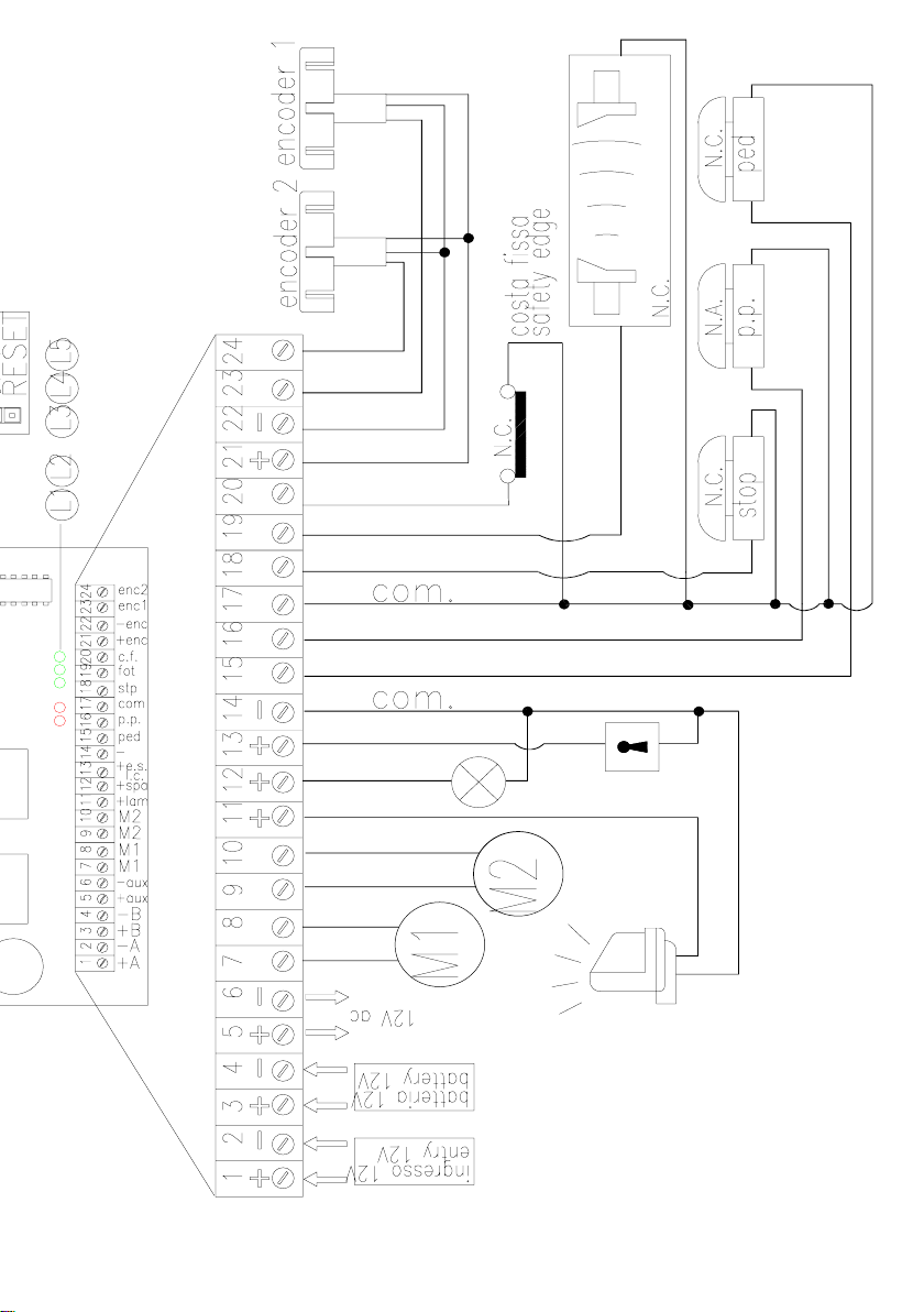
fig.1
Page 4

INSTALLAZIONE - INSTALLATION - INSTALLATION - INSTALLATION - INSTALACION
L’INST ALLAZIONE DELL ’APP ARECCHIA TURA DEVE ESSERE EFFETTUA T A “A REGOLA D’ARTE” DA
I
PERSONALE QUALIFICAT O COME DISPOSTO DALLA LEGGE 46/90.
NB : si ricorda l’obbligo di mettere a massa l’impianto nonché di rispettare le normative sulla sicurezza in
vigore in ciascun paese.
LA NON OSSER VANZA DELLE SOPRAELENCATE ISTRUZIONI PUÒ’ PREGIUDICARE IL BUON FUN-
ZIONAMENTO DELL ’APPARECCHIATURA E CREARE PERICOLO PER LE PERSONE, PERT ANT O LA
“CASA COSTRUTTRICE” DECLINA OGNI RESPONSABILITÀ’ PER EVENTUALI MAL FUNZIONAMENTI
E DANNI DOVUTI ALLA LORO INOSSERVANZA.
DAS GERÄT MUSS VON F ACHLEUTEN, DIE ÜBER DIE VOM GESETZ 46/90
D
VORGESCHRIEBENEN FACHKENNTNISSE VERFÜGEN, “F ACHGERECHT” INST ALLIERT WERDEN.
Bitte beachten: es wird daran erinnert, daß die Verpflichtung zur Erdung der Anlage sowie zur Einhaltung
der in dem jeweiligen Land gültigen Sicherheitsvorschriften besteht.
DAS NICHTEINHAL TEN DER OBENANGEFÜHRTEN ANLEITUNGEN KANN DEN EINW ANDFREIEN
BETRIEB DES GERÄTS BEEINTRÄCHTIGEN UND GEFAHRENSSITUA TIONEN FÜR PERSONEN
HERVORRUFEN. AUS DIESEM GRUND HAFTET DIE “HERSTELLERFIRMA” AUF KEINEN F ALL FÜR
EVENTUELLE AUF DAS NICHTEINHAL TEN DER ANLEITUNGEN ZURÜCKZUFÜHRENDE
BETRIEBSSTÖRUNGEN UND SCHÄDEN.
GB
THE EQUIPMENT MUST BE INST ALLED “EXPER TL Y” BY QUALIFIED PERSONNEL AS REQUIRED BY
LAW 46/90.
NB : it is compulsory to earth the system and to observe the safety regulations that are in force in each
country .
IF THESE ABOVE INSTRUCTIONS ARE NOT FOLLOWED IT COULD PREJUDICE THE PROPER
WORKING ORDER OF THE EQUIPMENT AND CREA TE HAZARDOUS SITUATIONS FOR PEOPLE.
FOR THIS REASON THE “MANUFACTURER” DECLINES ALL RESPONSIBILITY FOR ANY
MALFUNCTIONING AND DAMAGES THUS RESULTING .
L’INST ALLA TION DE L ’EQUIPEMENT DOIT ETRE REALISEE “SELON LES REGLES DE L’ART” P AR
F
LE PERSONNEL COMPETENT AYANT LES QUALITES REQUISES P AR LA LOI 46/90.
N.B.: nous rappelons l’obligation de mettre l’installation à la terre et de respecter les normes de sécurité en
vigueur dans le pays d’installation.
LA NON OBSER V A TION DES INSTRUCTIONS POURRAIT COMPROMETTRE LE BON
FONCTIONNEMENT DE L’APPAREILLAGE ET CREER UN DANGER POUR LES PERSONNES, P AR
CONSEQUENT LA MAISON DECLINE TOUTE RESPONSABILITE POUR D’EVENTUELLES
DETERIORA TIONS DUES A UNE UTILISA TION NON APPROPRIEE OU NON CONFORME AU MODE
D’EMPLOI.
LA INSTALACIÓN DEL EQUIPO TIENE QUE SER EFECTUADA CORRECT AMENTE POR PERSONAL
E
QUE REÚNA LOS REQUISITOS QUE ORDENA LA LEY 46/90.
P .D.: recordamos que es obligatorio conectar a tierra la instalación y respet ar todas las normativas relativas
a seguridad vigentes en cada país.
NO RESPETAR LAS INSTRUCCIONES ARRIBA INDICADAS PUEDE PERJUDICAR EL CORRECTO
FUNCIONAMIENTO DEL EQUIPO Y CONSTITUIR UN PELIGRO PARA LAS PERSONAS, POR LO
T ANTO, LA “EMPRESA F ABRICANTE” DECLINA TODA RESPONSABILIDAD POR POSIBLES
ANOMALÍAS DE FUNCIONAMIENTO Y DAÑOS QUE DE ELLO SE DERIVEN.
pag.1
Page 5

INDICE
VERZEICHNIS
CONTENTS
INDEX
INDICE
pag. 3
pag. 6
pag. 11
pag.16
pag. 21
pag. 26
pag. 31
DISEGNI, ZEICHNUNG , DRA WINGS, DESSINS, DIBUJOS.
ITALIANO
TEDESCO
INGLESE
FRANCESE
SPAGNOLO
DATI RIGUARDANTI LE APPARECCHIATURE, DATEN ZU DEN GERÄTSCHAFEN,
EQUIPMENT DA T A, DONNEES CONCERNANT LES EQUIPEMENTS,
DAT OS RELA TIVOS A LOS EQUIPOS.
pag.2
Page 6

COLLEGAMENTI ELETTRICI ELEKTROANSCHLÜSSE ELECTRICAL CONNECTION
CONNEXIONS ELECTRIQUES CONEXIONES ELÉCTRICAS
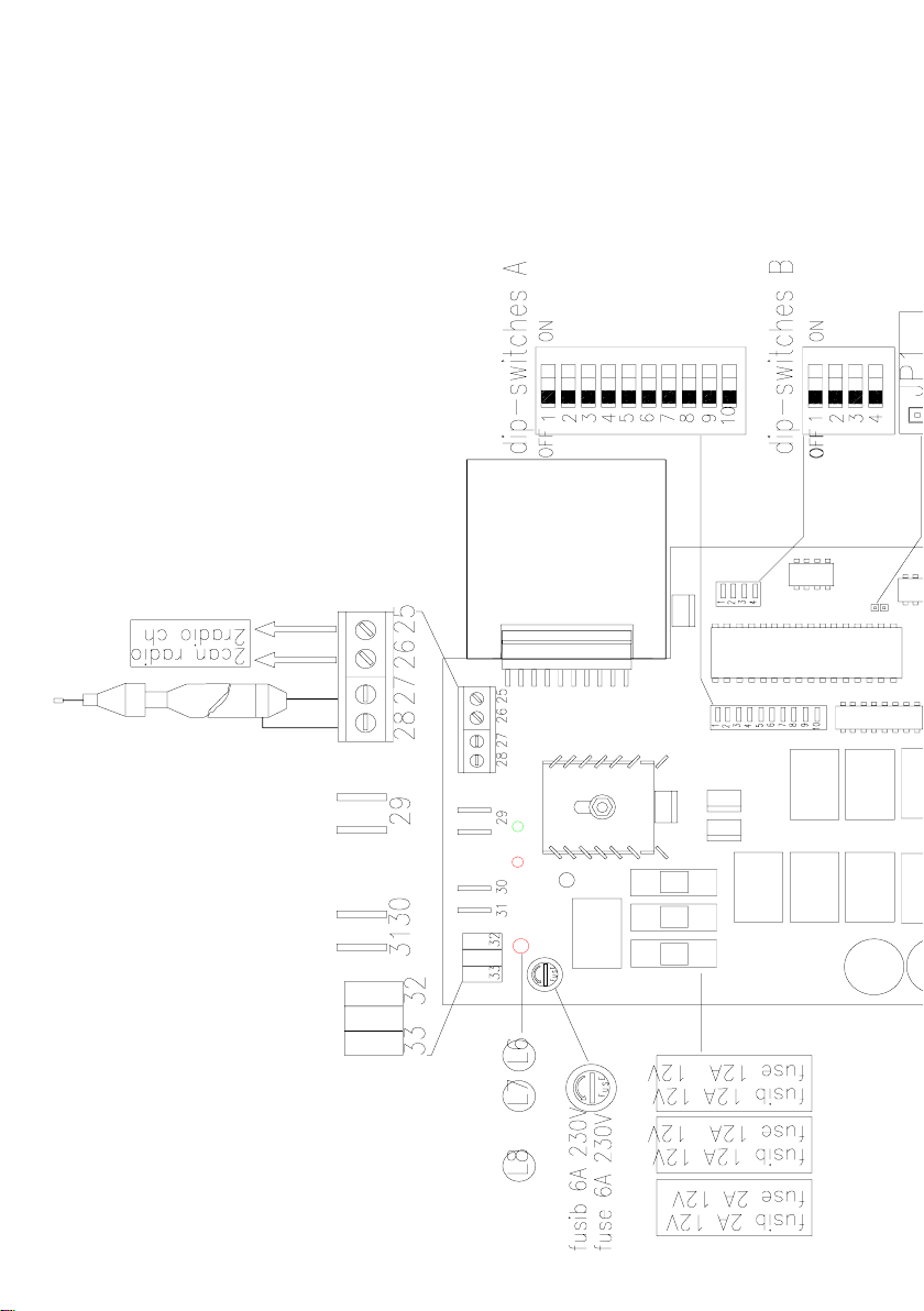
Se non uso la scheda raddrizzatrice, l’ingresso della tensione 230V è
I
portata direttamente sulla scheda comando come indicato in fig.2 e
quindi non utilizzo i morsetti 1-2. Se invece utilizzo la scheda
raddrizzatrice non devo collegare i morsetti 29-30-31-32-33 come
indicato in fig.3.
fig.2 fig.3
Falls die Gleichrichtungskarte nicht benützt wird, so wird der 230V Spannungseingang wie in Abb. 2 gezeigt
D
direkt auf die Steuerkarte gelegt, und daher werden die Klemmen 1-2 nicht verwendet. Wird die
Gleichrichtungskarte dagegen benützt, so dürfen die Klemmen wie 29-30-31-32-33 wie in Abb. 3 gezeigt nicht
angeschlossen werden.
If the rectifier card is not used, 230V input is taken directly to the control card as shown in fig. 2 and terminals 1-
GB
2 are therefore not used. If the rectifier is used, terminals 29-30-21-32-33 are not connected as shown in fig.3.
Si la carte redresseuse n’est pas utilisée, l’entrée de la tension 230 V est portée directement sur la carte de
F
commande comme l’indique la fig. 2 et les bornes 1-2 ne sont donc pas utilisées. Si par contre la carte
redresseuse est utilisée, il ne faut pas connecter les bornes 29-30-31-32-33 comme l’indique la fig. 3.
Si no se usa la tarjeta rectificadora, la entrada de la tensión 230V se coloca directamente en la tarjeta de man-
E
do, como indicado en la fig. 2 y, por consiguiente, no se usan los bornes 1-2. Si en cambio, se usa la tarjeta
rectificadora, no hay que conectar los bornes 29-30-31-32-33, como indicado en la fig. 3.
In 230V di linea; In 230V Linienstrom; 230V mains power input; In 230 V de ligne; Entrada 230V de línea.
1
In 220V al trasformatore; In 220V zum Transformator; 220V input to transformer; In 230 V au transformateur;
2
Entrada 220V al transformador.
Out 12Vac dal trasformatore; Out 12Vac vom Transformator; 12Vac output from transformer; Out 12 Vca du
3
transformateur; Salida 12Vca desde el transformador.
4
Out 12Vdc dalla scheda raddrizzatrice; Out 12Vdc von der Gleichrichtungskarte; 12Vdc output from rectifier
card; Out 12 Vcc de la carte redresseuse; Salida 12Vcc desde la tarjeta rectificadora.
SETTAGGIO DIP-SWITCHES EINSTELLEN DER DIP-SWITCHES DIP-SWITCH SETTING
REGLAGE DIP-SWITCHES REGULACIÓN DE LOS DIP-SWITCHES
pag.3
Page 7
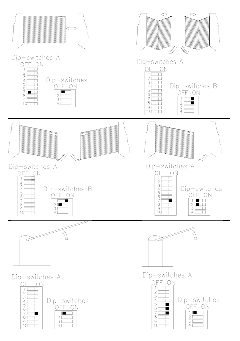
fig.4
fig.5
B45
fig.6
fig.7
B30
fig.8 fig.9
pag.4
Page 8
Schema elettrico per 2 motori; collegare solo l’encoder del motore 1.
I
Schaltplan für 2 Motoren; nur den Encoder des 1 Motors anschließen.
D
Electrical diagram for 2 motors; only connect the encoder of the
GB
first motor.
Schéma électrique pour 2 moteurs; connecter seulement l’encodeur
F
du 1er moteur.
Esquema eléctrico para 2 motores; conecte sólo el encoder del 1°
E
motor.
fig.10
fig.11
fig.12 fig.13
fig.14 fig.15
pag.5
Page 9

I
ALIMENTAZIONE 12V
LOGICA CON MICROPROCESSORE
REGOLAZIONE ELETTRONICA DELLA COPPIA MOTORE
RALLENTAMENTO MOTORI A FINE MANOVRA
RITARDI ANTA APERTURA E CHIUSURA
AUTOAPPRENDIMENTO TEMPO LA VORO E PAUSA
CONTROLLO STATI INGRESSO CON LED
PROTEZIONE INGRESSO 12V CON FUSIBILE
PROTEZIONE USCITA 12V CON FUSIBILE
CARICA BATTERIA INCORPORATO
COLLEGAMENTI ALLA MORSETTIERA
1-2
ALIMENT AZIONE 12 V 12 V cc INGRESSO voltaggio supplementare
+ Morsetto 1, - Morsetto 2. Contatti da usare siolo con scheda stabilizzatrice.
Ingresso BATTERIA A SECCO 12 V cc, 6A.
3-4
Questa batteria garantisce l’alimentazione al pannello per 24 h con il pannello in modalità stand-by , 20
minuti nel caso il motore sia in funzione (stimate 30 manovre).
+ Morsetto 3, - Morsetto 4.
USCITA 12 V Uscit a 12 V cc, max. 80 W.
5-6
Per alimentare RICEVITORI PERIFERICI, FOTOCELLULE etc..
Protetta con un fusibile a 2A (5x20).
+ Morsetto 5, - Morsetto 6.
Uscita motore M1 12 V cc, max 50 W.
7-8
Collegare la porta motore con la chiave elettrica, ad azione ritardata in chiusura (tempo regolabile con i
dip-switch 7A, 8A).
12 V MOTORE M2 Uscita motore M1 12 V cc, max 50 W .
9-10
Collegare la porta motore con la chiave elettrica, ad azione ritardata in chiusura (tempo
regolabile con i dip-switch 7A, 8A).
Uscita 12 V cc per LAMPEGGIANTE, max 20 W.
11-14
Con il Dip 2B è possibile selezionare la funzione LUCE DI CORTESIA.
+ Morsetto 11, - Morsetto 14 (Comune=14).
12-14
USCITA INDICATORE LUMINOSO 12 V cc , max 15 W.
E’ accesa dall’inizio di una manovra di apertura fino ad una chiusura completa del cancello.
+ Morsetto 12, - Morsetto 14 (Comune=14).
13-14
USCITA ELETTROSERRA TURA 12 V cc , max. 15 W .
Resta attiva per 1 secondo prima e 2 secondi dopo la partenza in apertura dell’anta ritardata in
chiusura (M1).
+ Morsetto 13, - Morsetto 14 (Comune=14).
Ingresso pulsante PEDONALE ( contatto Normalmente Aperto ); il suo funzionamento è analogo al
15-17
pulsante APRE/CHIUDI; il funzionamento dipende dal DIP1. (Comune=17).
PULSANTE APRE-CHIUDEIl PULSANTE APRE/CHIUDE (o P ASSO-P ASSO). La funzione di questo
16-17
input dipende dai dip switch 3A e 1A (SCHEDA COMANDO). E’ possibile, attraverso DS 3A, escludere
l’inversione di marcia durante la fase di apertura, o la funzione APRE/ST OP/ CHIUDE/STOP con il
DS 1A; il funzionamento dipende dal DIP1. Contatto Normalmente aperto. (Comune=17).
Con il DIP1 in ON e 2 motori le funzioni apre-chiude e pedonale sono attive, se il DIP è in OFF abbiamo
quanto segue:
con il DIP8 in OFF funzioni apre-chiude e pedonale normale,
con il DIP8 in ON il pulsante apre-chiude diventa solo pulsante apre,
con il DIP8 in ON il pulsante pedonale diventa pulsante chiude.
pag.6
Page 10

17-18
PULSANTEDI STOP . L ’attivazione di questo pulsante provoca lo stop del cancello qualsiasi manovra
stia facendo. Ripartirà di nuovo schiacciando il pulsante APRE/CHIUDE.
Contatto normalmente chiuso. (Comune=17).
17-19
FOTODISPOSITIVO input di sicurezza per FOTOCELLULE, COSTE MOBILI etc. Per il funzionamento
guardare le istruzioni sulla SCHEDA DI COMANDO.
Contatto normalmente chiuso. (Comune=17).
17-20
COSTA FISSA Durante la fase di apertura l’azionamento provocherà la richiusura per circa 2 secondi.
Contatto normalmente chiuso. (Comune=17).
Se il DIP1 è in posizione OFF (1 motore), funziona come costa fissa;
Se il DIP1 è in posizione OFF (2 motori), funziona come fotocellula; l’intervento solo in fase di chiusura
provocherà l’inversione del moto.
21-22-23
21-22-24
25-26
27-28
ENCODER MOTORE 1 (M1) INPUT ENCODER.
Morsetto n° 21,+ / marrone,
Morsetto n° 22, - / bleu,
Morsetto n° 23 impulso di comando / bianco.
ENCODER MOTORE 2 (M2) INPUT ENCODER. (solo per MEC2000).
Morsetto n° 21,+ / marrone,
Morsetto n° 22, - / bleu,
Morsetto n° 24 impulso di comando / bianco.
2° CANALE RICEVENTE USCITA DEL 2° CANALE RICEVENTE
Usando una ricevente a due canali è possibile controllare ad esempio: il dispositivo di illuminazione, un
altro dispositivo, etc..
Vedere le istruzioni relative al ricevitore per le specifiche sui collegamenti elettrici.
ANTENNA RICEVENTE INGRESSO ANTENNA RICEVENTE.
Collegare la CALZA al morsetto n° 28, il CA VO al morsetto n° 27. Se non si dispone di una adeguata
messa a terra si suggerisce di non collegare la calza dell’antenna.
CONTA TTI DA UTILIZZARE QUANDO NON SI IMPIEGA LA SCHEDA ST ABILIZZA TRICE.
29
Ingresso 12V cc da trasformatore toroidale (fig.2 - 3).
30-31
Ingresso 220V al trasformatore toroidale (fig.2 - 3).
32-33
Ingresso della tensione 220/230 V ac di linea (fig.2 - 3).
INSTALLAZIONE
1- Posizionare la scheda verticalmente.
2- Rispettare assolutamente le polarità.
3- Si consiglia di usare conduttori diversi per i vari circuiti.
4- La sezione dei cavi della linea dell’apparecchiatura e delle linee di alimentazione dei motori dovrà essere
calcolata in base alla loro lunghezza ed alla corrente assorbita.
sezione minima cavi alimentazione 220V 1.5 mm2;
sezione minima cavi alimentazione motore 12V 2.5 mm2;
5- Quando i circuiti di comando presentano linee molto lunghe (oltre i 50 m) è consigliabile il disaccoppiamento
con relè montati presso il quadro comando.
6- Le condutture entranti ed uscenti dell’apparecchiatura dovranno essere installate mantenendo preferibilmente
invariato l’iniziale grado di protezione (IP43).
7- In caso di intervento di un fusibile, questo dovrà essere sostituito con un altro avente uguali caratteristiche.
8- Cortocircuitare i contatti Normalmente Chiusi che non si dovessero utilizzare.
COLLAUDO DELL’IMPIANTO
I led piccoli verdi segnalano gli ingressi N.C., se i contatti sono chiusi i led devono essere accesi (se non
vengono usati degli i ngressi N.C., si devono collegare con il comune).
pag.7
Page 11

L1L2rosso
rosso
L3
verde
L4
verde
L5
verde
L6+L7
verde/
rosso
L7
verde
L8
rosso
Segnala il funzionamento del comando pedonale.
Segnala il funzionamento del comando passo-passo.
Segnala il funzionamento del comando stop.
Segnala il funzionamento dell’ ingresso fotocellula.
Segnala il funzionamento del dispositivo costa-fissa.
Segnala la presenza della tensione 12Vac nella scheda.
Segnala la presenza della tensione 12V dc nella scheda con alimentazione da batteria.
Segnala la presenza della tensione di alimentazione 220/230 V ai morsetti 32-33.
PROGRAMMAZIONE DEI DIP SWITCH
N° 1
N°2
N°3
N°4
N°5 - 6
APERTO/CHIUSO PULSANTE DI STOP ON stop abilitato.
Con questo dip-switch in posizione OFF il funzionamento del pulsante apre/chiude è quello descritto
nel punto dip-switch n.3A. Con il dip-switch in posizione ON azionando il pulsante apre/chiude avremo
le seguenti fasi: APRE - STOP - CHIUDE -ST OP - APRE etc.
FOTODISPOSITIVO IN APERTURA ON abilitato anche in apertura.
Con questo dip-switch in posizione OFF il fotodispositivo interviene solo nella fase di CHIUSURA, si
blocca per circa 2 secondi e poi fa un’apertura.
Con il dip-switch in ON il fotodispositivo interviene ANCHE in APERTURA, il cancello rimane fermo
finché l’ostacolo interrompe il raggio del fotodispositivo, al ripristino seguirà un’apertura.
PULSANTE APRE/CHIUDE IN APERTURA ON abilitato anche in apertura.
Con i dip-switch in posizione OFF azionando il pulsante apre/chiude si inverte la marcia solo in fase di
CHIUSURA. In posizione ON il pulsante apre/chiude inverte la marcia ANCHE in fase di APERTURA.
RICHIUSURA AUTOMA TICA ON abilitato.
In posizione OFF , una volta aperto il cancello, si richiuderà solo con un comando manuale.
In posizione ON, una volta aperto il cancello avremo una RICHIUSURA AUT OMA TICA dopo un tempo
PAUSA programmato.
RALLENTAMENT O 4 Livelli.
Per fase di rallentamento si intende la parte terminale della corsa del cancello nella quale viene data al
motore una tensione inferiore. La durata di questa fase è proporzionale agli impulsi rilevati dallo
encoder nella manovra di memorizzazione. E’ consigliato porre i DIP 5A e 6A in ON per le barriere.
DIP n° 5
OFF
OFF
ON
ON
DIP n° 6
OFF
ON
OFF
ON
4.68
12.5
37.5
50
%
ESEMPIO con 100 impulsi memorizzati:
95.32 impulsi velocità normale, 4.68 impulsi velocità rallentata
87.5 impulsi velocità normale, 12.5 impulsi velocità rallentata
62.5 impulsi velocità normale, 37,5 impulsi velocità rallentata
50 impulsi velocità normale, 50 impulsi velocità rallentata
DIP-SWITCH A
N°7 - 8
RITARDO ANT A (MEC2000) 4 Livelli.
La durata del ritardo è sempre proporzionale agli impulsi rilevati dall’encoder nella manovra di
memorizzazione. Sono disponibili 4 combinazioni. NB: se il dip 1B è posto su 1 motore e per la
versione MEC1000, questa funzione è esclusa.
pag.8
Page 12

DIP n°7
OFF
ON
OFF
ON
DIP n°8
OFF
OFF
ON
ON
%
R.AP
2.34
4.69
9.38
18.75
ESEMPIO con 100 impulsi memorizzati:
%
R.CH
2.34 impulsi ritardo apre, 4.69 impulsi ritardo chiude
4.69
4.69 impulsi ritardo apre, 9.38 impulsi ritardo chiude
9.38
9.38 impulsi ritardo apre, 18.75 impulsi ritardo chiude
18.75
18.75 impulsi ritardo apre, 37.5 impulsi ritardo chiude
37.5
N° 9 - 10 FRIZIONE ELETTRONICA 4 Livelli.
Il quadro tipo MEC1000 / MEC2000 è dotato di una circuitazione in grado di controllare la effettiva
velocità del cancello o indipendentemente delle due ante nel caso di un battente.
Il motore diventa così sensibile ad eventuali cali di velocità che possono essere conseguenza o di un
ostacolo o del finecorsa meccanico. Questa sensibilità può essere regolata su 4 livelli tramite i dipswitch 9A e 10A. Si consiglia agli installatori di optare per un livello di potenza medio.
DIP n° 9 DIP n° 10 LIVELLO DI POTENZA
OFF OFF 1 MASSIMA
ON OFF 2 MEDIO MASSIMA
OFF ON 3 MEDIO MINIMA
ON ON 4 MINIMA
DIP-SWITCH B
N° 1
N°2
N°3
N°4
Al termine delle operazioni di memorizzazione fare eseguire alla automazione una manovra completa (apre/
chiude), senza intervenire su alcun dispositivo.
ON è abilitato l’uso di 2 motori.
OFF è abilitato l’uso di un solo motore.
NB: 1 motore aziona i relè dei 2 motori in parallelo ma guarda solo l’encoder del motore M1.
Da usare per i basculanti.
Nella posizione dip7A in OFF si inserisce il colpo di inversione per evitare il bloccaggio del
motore.
ON è abilitato l’uso della luce di cortesia.
OFF è abilitato l’uso della elettroserratura.
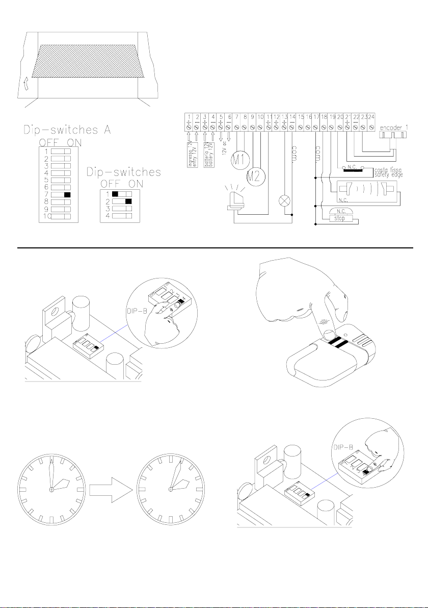
Nel caso di portoni industriali ad impacchettamento, il dip 2B deve essere posto in ON mentre
la regolazione dei dip A è ininfluente.
ON è abilitato l’uso del prelampeggio.
OFF questa funzione è disabilitata.
ON sono abilitate tutte le funzioni di memorizzazione.
OFF posizione in cui deve stare ad operazioni di memorizzazione finita.
MEMORIZZAZIONE TEMPO DI LAVORO E PAUSA
Sbloccare l’automazione ed aprire leggermente l’anta.
NB: solo per la barriera, portare l’asta a 45° di inclinazione rispetto all’orizzontale.
1-Portare il dip 4B in posizione di memorizzazione ossia in ON (fig.12).
2-Con il telecomando (fig. 13) dare un impulso eseguendo così una chiusura; nel caso l’anta si aprisse, invertire
la polarità del motore.
3-Effettuata la chiusura e con l’automazione in battuta, trascorso un tempo di circa 2 sec (fig.14), viene
eseguita automaticamente una apertura totale.
4-Ora il cancello è completamente aperto. Lasciare scorrere un tempo T (a piacere), quindi dare un impulso
che chiude l’anta. T diventa il T.C.A. (= TEMPO CHIUSURA AUT OMA TICA).
Durante tutte queste fasi il lampeggiante è in funzione.
pag.9
Page 13

5-Ora tutte le fasi apre/chiude sono memorizzate quindi si posizioni il dip 4B in posizione OFF (fig.15).
6-Durante il normale utilizzo si ha che: in fase di chiusura il cancello va in appoggio, mentre in fase di apertura
non raggiunge mai il finecorsa teorico.
MEMORIZZAZIONE APERTURA PEDONALE PER UN MOTORE
1- Portare in posizione ON il dip 4B, si accende il lampeggiante.
2- Premere il pulsante PEDONALE; inizia la manovra di apertura dello scorrevole collegato al motore M1.
3- Fermare il cancello premendo il pulsante PEDONALE nel punto desiderato.
4- Ripremere il pulsante PEDONALE o attendere che il tempo di pausa termini per la chiusura del cancello
5- Riportare il dip 4B nella posizione OFF e verificare lo spegnimento del lampeggiante.
La memorizzazione è così eseguita.
RESET DELLA MEMORIA
Qualora si vogliano variare tutte o alcune delle impostazioni precedentemente memorizzate si opera in questo
modo:
1- alimentare la scheda di comando,
2- toccare con la punta di un cacciavite i due piolini del jump JP1 per almeno 1 secondo,
3- i dati precedentemente memorizzati sono ora cancellati.
Durante questa operazione è indifferente la posizione occupata dal dip 4B.
pag.10
Page 14

D
STROMVERSORGUNG 12 V EINGEBAUTER
EMPFANGSTEIL LOGIK MIT MIKROPROZESSOR
ELEKTRONISCHE REGULIERUNG DES MOTORENDREHMOMENTS
MOTORENVERLANGSAMUNG BEI SCHALTENDE
VERZÖGERUNGEN BEI ÖFFNUNG UND SCHLIESSUNG DES FLÜGELS
SELBSTERLERNUNG DES BETRIEBS-UND PAUSENTAKTS
KONTROLLE DER EINGANGSZUSTÄNDE MIT LEDS
12V-EINGANGSSCHUTZ MIT SICHERUNG
12V-AUSGANGSSCHUTZ MIT SICHERUNG
EINGEBAUTES BATTERIELADEGERÄT
KLEMMBRETTANSCHLÜSSE LEISTUNGSTEIL
VERSORGUNGS SPANNUNGSEINGANG 12V cc.
1-2
Klemme 1 +, Klemme 2 -. Schaltplan für 2 Motoren; nur den Encoder des 1. Motors anschließen.
12 V TROCKENBA TTERIE EINGANG 12V cc 6Ah.
3-4
Diese Batterie gewährleistet die Eigenversorgung der Steuertafel für 24 h bei ruhender Tafel und 20’ bei
funktionierenden Motoren (30 Schaltungen ca.).
Klemme 3 +, Klemme 4 -.
AUSGANG 12 V cc max. 80W.
5-6
Für Versorgung: EXTERNE FUNKVERBINDUNGEN, FOTOZELLEN usw .
Schutz mit 2A-Sicherung (5x20).
Klemme 5 +, Klemme 6 -.
AUSGANG M1 Motor 12 V cc max. 50W.
7-8
Den Motor des Flügels mit der Elektroverriegelung und der verzögerten SCHLIESSUNG
anschließen (mit Dip-Schaltern 7A und 8A regulierbare Zeit).
AUSGANG M2 Motor 12 V cc max. 50W.
9-10
Den Motor des Flügels mit der verzögerten SCHLIESSUNG .
anschließen (mit Dip-Schalter 7A und 8A regulierbare Zeit).
AUSGANG für BLINKLICHT oder BELEUCHTUNG 12V cc max. 20W .
11-14
Klemme 11+, Klemme 14-, (14=Gemeinsame).
Mit der Dip-Schalter 2B wählt man die Funktion BELEUCHTUNG.
AUSGANG für KONTROLLAMPE 12V cc max. 15W.
12-14
Sie leuchtet von Beginn der Öffnung bis zur kompletten Schließung des Gatters auf.
Klemme 12+, Klemme 14-, (14=Gemeinsame).
AUSGANG für ELEKTROVERRIEGELUNG 12V cc max. 15W.
13-14
Bleibt 1 Sekunde vor und 2-6 Sekunden nach Beginn der Öffnung des für die Schließung verzögerten
Flügels aktiv (M1).
Klemme 13+, Klemme 14-, (14=Gemeinsame).
FUßGÄNGER Eingang T aste FUßGÄNGER (Kont akt normalerweise geöffnet ) ; ihre Funktion entspricht
15-17
dem der T aste ÖFFNET/SCHLIEßT, Hängt von Dip 1 ab
Klemme 15, (17 = Gemeinsame).
AUF-/ZU-DRUCKKNOPF AUF-/ZU-DRUCKKNOPF (oder SCHRITT für SCHRITT). Das Funktionieren
16-17
dieses Eingangs ist von den Dip-Schaltern Nr. 3A und Nr . 4A abhängig (HAUPTKARTE).
Durch den DS 3A kann die Laufrichtungsänderung während der Öf fnung ausgeschlossen werden,
oder die Funktion: AUF / HAL T / ZU / HAL T... mit DS 4A norm. off. Kontak; Hängt von Dip 1 ab.
Klemme 16+, (17 = Gemeinsame).
DIP 1 auf ON und 2 Motoren: Funktion Öffnet-Schließt und Fußgängerdurchgang
auf OFF:
mit DIP 8 auf OFF: Funktion Öffnet-Schließt und normaler Fußgängerdurchgang;
pag.11
Page 15

mit DIP 8 auf ON: Funktion Öffnet-Schließt wird nur zur Funktion Öffnet;
mit DIP 8 auf ON: Funktion Fußgängerdurchgang wird zur Funktion Schließt.
17-18
DRUCKKNOPF HALT. Bei Betätigung dieses Druckknopfs kommt jede gerade vom Gatter
ausgeführte Bewegung sofort zum Stehen. Das Gerät startet erst wieder , wenn der Druckknop f
AUF/ZU gedrückt wird. Norm. geschl. Kontakt. Klemme 18+, (17 = Gemeinsame).
17-19
SICHERHEITSEINGANG für LICHTEMPFINDLICHE EINRICHTUNGEN, MOBILE LEISTEN
usw. Für die Betriebsarten verweisen wir auf die Anleitungen zur HAUPTKAR TE.
Norm. geschl. Kontakt.
Klemme 19+, (17 = Gemeinsame).
17-20
FIXE LEISTE EINGANG . Während der Öffnung verursacht der Antrieb das erneute Schließen für ca.
2 Sekunden.
Norm. geschl. Kontakt.
Klemme 20+, (17 = Gemeinsame).
Ist DIP 1 auf OFF (1 Motor), funktioniert er als feste Sicherheitsleiste;
Ist DIP 1 auf ON (2 Motoren) funktioniert er als Photozelle: das Ansprechen nur in Schließung verursacht
die Umkehrung der Bewegung.
21-22-23
21-22-24
25-26
27-28
CODIEREREINGANG MOTOR M1.
Klemme Nr. 21 + / braun
Klemme Nr. 22 - / blau
Klemme Nr. 23 Impulseingang / weiß
CODIEREREINGANG MOTOR M2 (nur für Ausf. MEC2000).
Klemme Nr. 21 + / braun
Klemme Nr. 22 - / blau
Klemme Nr. 24 Impulseingang / weiß.
KONTAKT AUSGANG des ZWEITEN FUNKKANALS.
Bei Einsatz eines zweikanaligen Empfangsteils ist es beispielshalber möglich, Beleuchtungsanlagen,
ein anderes Gerät usw. zu steuern. Fur die technischen Merkmale des Kontakt verweisen wir auf die
Anleitungen zum Empfangsteil.
EINGANG EMPFANGSANTENNE.
MANTEL an Klemme Nr . 28, ZENTRALE an Klemme Nr. 27.
Wenn man über keine geeignete Erdung verfügen sollte, ist es ratsam, den Mantel der Antenne
(Klemme Nr. 28) nicht anzuschließen.
ZU BENÜTZENDE KONTAKTE OHNE GEBRAUCH DER STABILISIERUNGSKARTE
29
12 Vdc Eingang vom Ringtransformator (Abb. 2 - 3) .
30-31
220V Eingang zum Ringtransformator (Abb. 2 - 3).
32-33
220/230 Vac Eingang der Linienspannung (Abb. 2 - 3).
INSTALLATION
1- Die Karte vertikal positioniert werden muß.
2- Die Polaritäten unbedingt einhalten.
3- Für die verschiedenen Kreise empfiehlt sich der Einsatz verschiedener Leiter.
4- Der Kabelquerschnitt der Geräteleitung sowie der Speiseleitungen der Motoren muß im Hinblick auf deren
Länge und die Stromentnahme berechnet werden.
ein Schnitt von mindestens 1.5 mm2 für die Versorgungskabel,
ein Schnitt von mindestens 2.5 mm2 für die Motoren kabel.
5- Wenn die Steuerkreise über sehr lange Leitungen (über 50 Meter) verfügen, ist es ratsam, sie von bei der
Steuerschalttafel montierten Relais zu entkoppeln.
pag.12
Page 16

6- Die in das Gerät ein- bzw. aus ihm austretenden Leiter müssen vorzugsweise so installiert werden, daß der
anfängliche Schutzgrad (IP43) unbeeinträchtigt bleibt.
7- Wenn eine Sicherung ausspringt, so muß diese mit einer gleichartigen ausgewechselt werden.
8- Die normalerweise geschlossenen Kontakte, falls diese nicht verwendet werden sollen, kurzgeschlossen
werden müssen.
ANLAGENPRÜFUNG
Diese Steuerschalttafeln sind mit einigen, während der Prüfphase sehr nützlichen Signal-Leds ausgestattet:
Die kleinen grünen LEDs zeigen die NC-Eingänge an; wenn die Kontakte geschlossen sind, müssen die LEDs
eingeschaltet sein (werden keine NC-Eingänge benützt, so müssen sie an den gemeinsamen Leiter angeschlossen
werden).
L1
L2
L3
L4
L5
L6+L7
L7
L8
Rote
Rote
Grünen
Grünen
Grünen
Grünen/
Rote
Grünen
Rote
Meldet die Aktivierung der Funktion Fußgänger .
Meldet die Aktivierung der Funktion Schrittbetrieb.
Meldet die Aktivierung der Funktion S top.
Meldet die Aktivierung des Photozelleneingangs.
Meldet die Aktivierung der V orrichtung feste Sicherheitsleiste.
Meldet das Vorhandensein der 12V ac S pannung in der Karte.
Meldet das Vorhandensein der 12Vdc S pannung in der Karte mit S peisung durch Batterie.
Meldet das Vorhandensein der 220/230V S peisespannung an den Klemmen 32-33.
PROGRAMMIERUNG DER DIP-SCHALTER
DIP-SWITCH A
N° 1
N°2
N°3
N°4
N°5 - 6
“AUF/ZU”-DRUCKKNOPF MIT STOP ON: mit STOP.
Mit diesem Dip-Schalter auf OFF funktioniert der Druckknopf “Auf/Zu” wie bei Dip-Schalter Nr. 3A
beschrieben. Steht dieser Dip-Schalter auf ON hat man beim Drücken des Knopfs “Auf/Zu” folgende
Phasen: AUF - STOP - ZU - STOP.
LICHTEMPFINDLICHE VORRICHTUNG BEI ÖFFNUNG ON: auch bei Öffnung aktiviert.
Mit diesem Dip-Schalter auf OFF spricht die lichtempfindliche Vorrichtung nur bei der SCHLIESSUNG
AN, sie blockiert sich für ca. 2 Sekunden und geht dann auf ÖFFNUNG über.
Steht dieser Dip-Schalter auf ON, spricht die lichtempfindliche V orrichtung AUCH bei der ÖFFNUNG
an, das Gatter bleibt so lange stehen, so lange das Hindernis den Wirkungsbereich der lichtempf.
Vorrichtung unterbricht; sodann folgt eine Öffnung.
“AUF/ZU”-DRUCKKNOPF BEI ÖFFNUNG ON: auch bei Öffnung aktiviert.
Mit diesem Dip-Schalter auf OFF wird die Laufrichtung bei Drücken des “Auf/Zu”-Druckknopfs nur
während der SCHLIESSUNG geändert.
Steht er auf ON ändert der “Auf/Zu”-Druckknopf die Laufrichtung auch während der ÖFFNUNG.
AUTOMATISCHE SCHLIESSUNG ON: aktiviert.
Auf OFF schließt sich das Gatter erst bei einem MANUELL gegebenen Steuerbefehl.
Auf ON schließt sich das Gatter nach einer mit PAUSA programmierten P AUSEN-Zeit
AUTOMATISCH.
VERLANGSAMUNG 4 Stufen.
Unter einer Verlangsamungsphase versteht man die Endphase beim Gatterlauf, bei der dem Motor
eine niedrigere Spannung zugeführt wird. Die Dauer diese Phase hängt von denen vom Codierer
bei der Speicherung erfaßten Impulsen ab. Für die Automatisierung von Schranken empfehlen wir
eine 50%ige Verlangsamung.
pag.13
Page 17

DIP n° 5
OFF
OFF
ON
ON
DIP n° 6
OFF
ON
OFF
ON
4.68
12.5
37.5
50
%
BEISPIEL mit 100 gespeicherten Impulsen:
95,32 Impulse normale Geschwindigkeit
4,68 Impulse verlangsamte Geschwindigkeit.
87,5 Impulse normale Geschwindigkeit
12,5 Impulse verlangsamte Geschwindigkeit
62,5 Impulse normale Geschwindigkeit
37,5 Impulse verlangsamte Geschwindigkeit
50 Impulse normale Geschwindigkeit
50 Impulse verlangsamte Geschwindigkeit
N°7 - 8
N°9-10
N° 1
N°2
N°3
FLÜGELVERZÖGERUNGEN (MEC 2000)
Die Dauer der Verzögerung hängt immer von denen vom Codierer bei der S peicherung erfaßten
Impulsen ab. Es sind 4 Kombinationen disponibel. MERKE: Wenn der Dip-Schalter 1B auf 1
MOTOR steht und bei der Ausführung MEC 1000 ist diese Funktion ausgeschlossen.
DIP n°7
OFF
ON
OFF
ON
ELEKTRONISCHE KUPPLUNG 4 Stufen.
Die Schaltfelder vom T yp MEC 1000 und MEC 2000 sind mit einem Kreis ausgestattet, der in der Lage ist,
die effektive Geschwindigkeit des Gatters bzw. im Fall eines Flügel-Gatters, der beiden Flügel unabhängig
zu steuern. Der Motor reagiert so sehr sensibel auf eventuelle Geschwindigkeitsabfälle, die auf ein
Hinderniß oder den mechanischen Endschalter zurückgeführt werden können. Diese Feinfühligkeit kann
mit den Dip-Schaltern 9A und 10A auf 4 Ebenen reguliert werden. Den Installateuren wird ein mittleres
Leistungsniveau empfohlen.
DIP n° 9 DIP n° 10 FEINFÜHLIGKEITS STUFE
OFF OFF 1 HÖCHST STUFE
ON OFF 2 MITTLERE HÖCHST STUFE
OFF ON 3 MITTLERE MINDEST STUFE
ON ON 4 MINDEST STUFE
ON der Gebrauch von 2 Motoren ist aktiviert.
OFF der Gebrauch von nur 1 Motor ist aktiviert.
ON die Funktion Höflichkeitslicht ist aktiviert.
OFF die Funktion Elektroschloss ist aktiviert.
ON die Funktion Vorblinken ist aktiviert.
OFF diese Funktion ist deaktiviert.
DIP n°8
OFF
OFF
ON
ON
NB: 1 Motor betätigt die Relais der 2 parallelgeschalteten Motoren, berücksichtigt aber nur den
Encoder des Motors M1.
Für Schwingtore zu verwenden.
Wenn Dip7A auf OFF ist, wird der Umkehrungsstoß eingeschaltet, um die Blockierung des
Motors zu vermeiden.
Im Falle von faltbaren Industrietoren muss der Dip 2B auf OFF gestellt werden, wogegen die
Einstellung des Dip A keinen Einfluss hat.
%VERZ.
ÖFFN.
2.34
4.69
9.38
18.75
%VERZ.
SCHL.
4.69
9.38
18.75
37.5
BEISPIEL mit 100 gespeicherten Impulsen:
2,34 ImpulseVerzögerung auf 4,69 Impulse V erzögerung zu
4,69 ImpulseVerzögerung auf 9,38 Impulse V erzögerung zu
9,38 ImpulseVerzögerung auf 18,75 Impulse V erzögerung zu
18,75 ImpulseVerzögerung auf 37,5 Impulse V erzögerung zu
DIP-SWITCH B
pag.14
Page 18

N°4 ON alle Speicherfunktionen sind aktiviert.
OFF der Dip-Switch muss sich in dieser Position befinden, wenn alle Speichervorgänge sind beendet.
Der Automatisierung am Ende der S peichervorgänge ohne Betätigung von Vorrichtungen eine komplette
Bewegung (öffnet/schließt) ausführen lassen.
EINSPEICHERN DER BETRIEBS- UND PAUSENZEIT
Das T or lecht öffnen. Eingänge geschlossen sine (grüne Leds an).
NB: bringen sie die stange in eine 45° position von auf der horizontalen.
1- Die Dip 4B auf Stellung EINSPEICHERUNG AKTIVIERT bringen (siehe Abb. 12).
Es geht das Blinklicht an .
2- Den Druckknopf AUF/ZU* (siehe Abb.13) drücken und sich vergewissern, daß sich das Gatter zuerst schließt
(aus diesem Grund ist es ratsam, mit leicht geöffneten Gatterflügeln anzufangen). Sollte dies nicht der Fall
sein, die Polarität der Motoren austauschen.
3- Nach dem Scließen und mit Schiebegatter/Schranke am Anschlag, wird nach einer Zeit von etwa 2 Sekunden
eine Gesamtöffnung ausgeführt (sie Abb.14), (Automatisch Weise).
4- Das T or ist nun vollkommen geöffnet. Eine bestimmte Zeit T (beliebig) vergehen lassen, dann einen
Impuls zum Schließen des Schiebetors/der Schranke geben.
T wir T.C.A. (=Automatische Schließzeit = A.S.Z.).
Während dieser Phasen ist das Blinklicht in Betrieb.
5- Nun sind alle Öffnungs/Schließphasen gespeichert und die Dip-Schalten 4B kann wieder auf NORMAL
oder BENUTZUNG gestellt werden (siehe Abb. 15).
6- Während der normalen Benutzung: stützt das T or in der Schließphase auf, wogenen es in der Öffnungsphase
den theoretischen Endanschlag nie erreicht.
SPEICHERUNG DER FUßGÄNGERÖFFNUNG FÜR EINEN MOTOR
1- Die Überbrückung Dip 4B auf SPEICHERUNG EIN stellen; das Blinklicht schaltet sich ein.
2- Die T aste FUßGÄNGER drücken; der an den Motor M1 angeschlossene T orflügel oder das Schiebetor
beginnt den Öffnungsvorgang.
3- Das T or durch Druck auf die Taste FUßGÄNGER am gewünschten Punkt anhalten.
4- Die T aste FUßGÄNGER erneut drücken und warten, bis die Pausezeit für das Schließen des Tors beendet
ist.
5- Die Überbrückung Dip 4B wieder auf SPEICHERUNG AUS stelle und prüfen, dass sich das Dlinklicht
ausschaltet.
RESET DER STEUERSCHALTTAFEL
Will man alle oder ein paar der vorher gespeicherten Eingaben verändern, so ist wie folgt vorzugehen:
1 – die Steuerkarte speisen,
2 – mit der Spitze eines Schraubenziehers die zwei S tifte von Jump JP1 mindestens 1 Sekunde lang berühren,
3 – die vorher gespeicherten Daten sind nun gelöscht.
Während dieses Vorgangs kann Dip 4B in beliebiger Position sein.
pag.15
Page 19

GB
12 V SUPPL Y VOL T AGE
BUILT-IN RECEIVER
MICROPROCESSOR LOGIC
ELECTRONIC CONTROL OF MOTOR TORQUE
MOTOR DECELERATION AT THE END OF THE MANOEUVRE
DOOR OPENING-CLOSING DELAY
SELF-LEARNING OF WORK AND PAUSE TIME
CONTROL OF INPUT STATE WITH LEDS
12 V INPUT PROTECTION WITH FUSE
12 V OUTPUT PROTECTION WITH FUSE
BUILT-IN BATTERY CHARGER
CONNECTIONS TO TERMINAL BOARD
12 V dc supply voltage INPUT .
1-2
+ Terminal 1, - T erminal 2. Cont acts to use only with rectifier card.
12 V dc DRY BA TTERY INPUT, 6Ah.
3-4
This battery guarantees power to the panel for 24 hours with the panel in waiting state, 20 minutes if the
motor is running (approx. 30 manoeuvres).
+ T erminal 3, - T erminal 4.
12 V dc OUTPUT , max. 80 W .
5-6
T o power OUTDOOR RECEIVERS, PHOTOELECTRIC CELLS etc.
Protected with an 2A fuse (5x20).
+ T erminal 5, - T erminal 6.
12 V dc M1 motor OUTPUT , max 50 W . Connect motor of door with the electric lock, delayed in CLOSING
7-8
(time adjustable with dip switches 7A a 8A).
12 V dc M2 motor OUTPUT , max 50 W (only for MEC 2000 vers.)
9-10
Connect motor of door delayed in OPENING (time adjustable with dip switches 7A and 8A).
12 V dc OUTPUT for FLASHING LIGHT , max. 20 W .
11-14
+ T erminal 1 1, - terminal 14, (14=Commun).
With Dip 2B in ON position you can select the COURTESY LIGHT function.
12 V dc INDICAT OR LIGHT OUTPUT , max. 15 W .
12-14
It is on from the beginning of the opening manoeuvre up until the gate is completely closed.
+ T erminal 12, - terminal 14, (14=Commun).
12 V dc ELECTRIC LOCK OUTPUT , max. 15 W .
13-14
It is active for 1 second before and 2-6 seconds after the gate starts opening, delayed in closing (M1).
+ T erminal 13, - terminal 14, (14=Commun).
PEDESTRIAN push button input (Normally Open contact); its function is identical to that of the
15-17
OPEN/CLOSE, It depends on DIP-1.
T erminal 15, 17=Common.
OPEN/CLOSE PUSH BUTTON (or STEP-BY -STEP). The function of this input depends on dip
16-17
switches 3A and 4A (COMMAND CARD). It is possible, via DS3A, to exclude reversal of direction
during opening, or the OPEN/STOP/ CLOSE/STOP function with DS4A, it depends on DIP-1.
Normally open contact.
T erminal 16, 17=Common.
With DIP-1 in the ON position and 2 motors, both open-close and pedestrian functions are operative
In the OFF position we have the following:
with DIP-8 OFF , open-close and normal pedestrian functions;
with DIP-8 ON, the open-close function becomes open switch only;
with DIP-8 ON, the pedestrian function becomes close switch.
pag.16
Page 20

STOP PUSH BUTTON. Activation of this push button causes the gate to stop whatever manoeuvre it
17-18
was doing. It will only start again by pressing the OPEN/CLOSE push button.
Normally closed contact.
T erminal 18, 17=Common.
17-19
SAFETY INPUT for PHOTO-DEVICES, MOBILE EDGES etc. For operating modes please see
the COMMAND CARD instructions. Normally closed contact.
T erminal 19, 17=Common.
17-20
FIXED EDGE INPUT . During the opening phase, activation causes it to close again for approximately 2
seconds.
Normally closed contact.
T erminal 20, 17=Common.
If DIP-1 is in the OFF position (1 motor), it works as a fixed edge;
If DIP-1 is in the ON position (2 motors) it works as a photocell: a change of direction can be made only
if activated during the closing phase.
21-22-23
21-22-24
25-26
27-28
MOTOR M1 ENCODER INPUT .
T erminal n° 21,+ / brown.
T erminal n° 22, - / bleu.
T erminal n° 23 pulse input / white.
MOTOR M2 ENCODER INPUT. (only for MEC2000 vers.).
T erminal n° 21,+ / brown.
T erminal n° 22 - / bleu.
T erminal n° 24 pulse input / white.
SECOND RECEIVER CHANNEL CONT ACT OUTPUT.
Using a two-channel receiver it is possible to control, for instance: lighting systems, another
unit, etc. See receiver instructions for technical contact specifications.
RECEIVER AERIAL INPUT.
Connect SHIELD to terminal n° 28, WIRE to terminal n° 27. If an adequate earthing system is not
available we suggest you do not connect the aerial shield (terminal n° 28).
CONTACTS TO USE WHEN THE RECTIFIER CARD IS NOT USED
29
12Vdc input from toroidal transformer (fig.2-3).
30-31
220V input to toroidal transformer (fig.2-3).
32-33
220/230 V ac mains power input (fig.2-3).
INSTALLATION
1- Position the card vertically.
2- It is essential to observe polarities.
3- Different wires should be used for the various circuits.
4- Wire cross section of the equipment’s line and of the motors’ supply lines should be calculated on the basis of
their length and on the current absorbed.
choose alimentation 220V cable cross sections of at least 1.5 mm²
choose motor 12V alimentation cable cross sections of at least 2.5 mm²
5- Decoupling is advisable whenever control circuits have extremely long lines (longer than 50 m) with elays
installed on the control panel.
6- Ducts leading to and from the equipment must be connected leaving, as far as possible, their initial rotection
level untouched (IP43).
7- If a fuse blows it has to be replaced with another one that has the same identical characteristics.
8- Short circuit any Normally Closed contacts that are not going to be used.
NB : it is compulsory to earth the system and to observe the safety regulations that are in force in each
country
pag.17
Page 21

FINAL TEST OF THE SYSTEM
These control panels are fitted with several indicator LEDs that can help during the final testing phase, (if N.C.
inputs are not used it is necessary to connect them to the common). The small green LED’s indicate N.C.
inputs, if the contacts are closed the LED’s must be on (if N.C. inputs are not used, they must be connected to
the common conductor).
L1
L2
L3
L4
L5
L6+L7
L7
L8
red
red
green
green
green
green/
red
green
red
Indicates the pedestrian command is working.
Indicates the step-by-step command is working.
Indicates the stop command is working.
Indicates the photocell input is working.
Indicates the fixed edge device is working.
Indicates the presence of 12Vac in the card.
Indicates the presence of battery powered 12Vdc in the card.
Indicates the presence of 220/230 V mains power at terminals 32-33.
DIP SWITCH PROGRAMMING
DIP-SWITCH A
N° 1
N°2
N°3
N°4
N°5 - 6
OPEN/CLOSE PUSH BUTTON WITH STOP ON stop enabled.
With this dip switch OFF the open/close push button functions as described in the point dip switch
n.3A. With the dip switch ON, by pressing the open/close push button we will have the following
phases: OPEN - STOP - CLOSE - STOP - OPEN etc.
PHOTO DEVICE IN THE OPENING PHASE ON also enabled in opening.
With this dip switch OFF the photo device functions only in the CLOSING phase, it stops for about 2
seconds and then causes an OPENING phase.
With the dip switch ON the photo device also functions in the OPENING phase; the gate will stay still
until the obstacle interrupts the photo device’s beam; the gate will open when reset.
OPEN/CLOSE PUSH BUTTON IN THE OPENING PHASE ON also enabled in opening.
With this dip switch OFF by pressing the open/close push button direction will be reversed only in the
CLOSING phase. With the dip switch ON the open/close push button will ALSO reverse the direction
in the OPENING phase.
AUTOMATIC RECLOSING ON enabled.
With this dip switch OFF , once the gate is open, it will only close again if a manual command is given.
With the dip switch ON, once the gate is open, it will CLOSE AGAIN AUTOMATICALLY after a set
programmed PAUSE time.
SLOWING DOWN 4 Levels.
By slowing down we mean when the gate reaches the end of its travel and the motor is supplied with a
lower voltage. The length of time of this phase is proportional to the pulses detected by the encoder
in the memorization manoeuvre. For the automation of bars we suggest a 50% deceleration.
DIP n° 5
OFF
OFF
ON
ON
DIP n° 6
OFF
ON
OFF
ON
4.68
12.5
37.5
50
%
EXAMPLE with 100 memorized pulses:
95.32 pulses at normal speed, 4.68 pulses at a reduced speed
87.5 pulses at normal speed, 12.5 pulses at a reduced speed
62.5 pulses at normal speed, 37.5 pulses at a reduced speed
50 pulses at normal speed, 50 pulses at a reduced speed
pag.18
Page 22

N° 7 - 8
N° 9 - 10
DOOR DELA Y (MEC 2000) 4 Levels.
The length of delay time is always in proportion to the pulses detected by the encoder in the memorization
manoeuvre. There are 4 different combinations to choose from. N.B. If dip-switch 1B is positioned on 1
MOTOR, and for the MEC 1000 version, this function is excluded.
DIP n°7
OFF
ON
OFF
ON
ELECTRONIC FRICTION 4 Levels.
MEC 1000 and MEC 2000 type panels are fitted with circuits that can control the gate’s actual speed or
independently control two wings of the same gate. The motor becomes highly sensitive to any reductions
in speed that could be caused by an obstacle or the mechanical end limit device.
This sensitivity can be adjusted on the four levels by means of dip switches 9 and 10.
Installers should choose a medium power level.
DIP n° 9 DIP n° 10 LEVEL OF SENSITIVITY
OFF OFF 1 MAXIMUM
ON OFF 2 MEDIUM MAXIMUM
OFF ON 3 MEDIUM MINIMUM
ON ON 4 MINIMUM
DIP n°8
OFF
OFF
ON
ON
OP.D
%
2.34
4.69
9.38
18.75
EXAMPLE with 100 memorized pulses:
CL.D
%
2.34 pulses delay open 4.69 pulses delay close
4.69
4.69 pulses delay open 9.38 pulses delay close
9.38
9.38 pulses delay open 18.75 pulses delay close
18.75
18.75 pulses delay open 37.5 pulses delay close
37.5
DIP-SWITCH B
N° 1
N°2
N°3
N°4
After memorising, make the automatic system carry out a complete manoeuvre (open/close) without activating
any devices.
ON 2 motors are enabled.
OFF just 1 motor is enabled.
NB: 1 motor activates the relays of both motors in parallel but only reads from the M1 motor
encoder.
For use with up-and-over doors
When dip 7A is OFF, the reversal stroke is enabled to prevent the motor from locking.
ON enables the courtesy light.
OFF enables the electric lock.
As regards large folding industrial doors, dip 2B must be ON while the position of dip A is
irrelevant.
ON the pre-flashing function is enabled.
OFF function disabled.
ON all memorising functions are enabled.
OFF correct position when the memorising procedure has terminated.
MEMORIZING WORK TIME AND PAUSE
Lightly open the gate.
NB: for the barrier, position the bar at 45° from the horizontal ground line.
1- Place the Dip-switch 4B on the MEMORIZING ENABLED position = ON position (fig. 12). The flashing light
turns on.
2- Press the OPEN/CLOSE* push button (fig. 13) and check on the gates that the first manoeuvre is a closing
one (for this reason it is recommended to start with the gates slightly open); if this is not the case, reverse
motor polarities.
pag.19
Page 23

3- Having reached the closed position, after 2 seconds the motors automatically will start the opening
manoeuvre. Wait for the manoeuvre to be completed (when the motors have stopped).
4- Now the gate is completely opened.
Let a T time elapse (fig.14 whatever you want); after which give a pulse that will close the sliding gate/boom
gate.
T becomes the T.C.A. (=AUTOMA TIC RECLOSING TIME).
During all these phases the flascing light turns on.
5- Now work time and pause have been memorized.
Place the Dip-switch 4B back onto the MEMORIZING
EXCLUDED position = OFF position (fig. 15) and check that the flashing light turns off.
6- When the gate is being used normally it will close touching, while when it opens it will never reach the
theorical stop point.
PEDESTRIAN OPENING MEMORISATION FOR ONE MOTOR
1- Bring Dip 4B into the MEMORISATION ENABLE position; the blinking light will turn on.
2- Press the PEDESTRIAN push button; the wing gate will start opening or the sliding gate connected to the M1
motor.
3- Stop the gate by pressing the PEDESTRIAN push button in the point wanted.
4- Either press the PEDESTRIAN push button again or wait for the pause time to elapse for the gate to close.
5- T ake Dip 4B back into the MEMORISA TION EXCLUDED position and make sure the blinking light is of f.
CONTROL CARD’ RESET
If you wish to vary some or all the previously memorised settings proceed as follows:
1- power the control card;
2 - touch the two JP1 jump pins for at least 1 second with the tip of a screwdriver;
3 - the previously memorised settings have now been cancelled.
During this operation the position of dip 4B is irrelevant.
pag.20
Page 24

F
ALIMENTATION 12V
RECEPTEUR INCORPORE
LOGIQUE AVEC MICROPROCESSEUR
REGLAGE ELECTRONIQUE COUPLE MOTEURS
RALENTISSEMENT MOTEURS A LA FIN DE LA MANOEUVRE
RETARDS PORTE OUVERTURE ET FERMETURE
AUTOAPRENTISSAGE TEMPS DE TRA V AIL ET DE PAUSE
CONTROLE DE L’ETAT DES ENTREES PAR VOYANTS LUMINEUX
PROTECTION ENTREE 12V AVEC FUSIBLE
PROTECTION SORTIE 12 V AVEC FUSIBLE
CHARGEUR DE BATTERIE INCORPORE
CONNEXION DU COFFRET DES BORNES
1-2
ENTREE tension d’ALIMENTA TION 12 V c.c.
borne 1+ , borne 2. Contacts à utiliser uniquemnent avec carte stabilisatrice.
ENTREE BATTERIE SECHE 12 V c.c. 6 Ah
3-4
Cette batterie garantit l’autoalimentation du pupitre pendant 24 H avec pupitre au repos, 20’ avec
moteurs en marche (30 manoeuvres environ).
Borne 3 +, borne 4 -.
SORTIE 12V c.c. 80W max.
5-6
Pour alimentation: RADIOS EXTERNES, CELLULES PHOTOELECTRIQUES, etc.
Protection avec FUSIBLE de 2A (5x20)
Borne 5 +, borne 6-.
SORTIE M1 moteur 12 V c.c. 50W max.
7-8
Connecter le moteur de la porte avec la serrure élect. et retardée en FERMETURE (temps réglable
avec interrupteurs à positions multiples 7A et 8A).
SORTIE M2 moteur 12V c.c. 50W max. (version MEC 2000).
9-10
Connecter le moteur de la porte retardée en OUVERTURE (uniquement pour la temps réglable avec
interrupteurs multiples 7A et 8A).
SORTIE pour VOYANT LUMINEUX 12V c.c. 20Wmax.
11-14
Borne 11 +, borne 14-, (14=commune).
Par l’intermédiaire du Dip 2B, on sélectionne la fonction LUMIERE DE COURTOISIE.
SORTIE POUR TEMOIN 12V c.c. 15W max.
12-14
OUVERTE Il est allumé dès le début d’une manoeuvre d’ouvertu d’ouverture jusqu’à la fermeture
complète de la aautomation.
Borne 12 +, borne 14 -, (14=Commune).
SORTIE pour SERRURE ELECTRIQUE 12V c.c. 1W max.
13-14
Elle est active pendant 1 seconde avant et 2-6 sec. après le départ en ouverture de la porte
retardée en fermeture (M1).
Borne 13 +, borne 14 -, (14=Commune).
entrée bouton PIETONS (contact Normalement Ouvert); son fonctionnement est analogue au
15-17
bouton OUVRE/FERME, Dépend du dip-switch 1
Borne 15 , 17 = Commune.
Le BOUTON OUVRE/ FERME (ou P AS A PAS) fonctionnement de cette entrée dépend des
16-17
interrupteurs à positions multiples n° 3A et n° 4A (FICHE COMMANDE).
Par l’intermédiaire de l’int. à positions multiples, il est possible d’exclure l’inversion de marche pendant
l’ouverture, ou bien la fonction: OUVRE/STOP/FERME/STOP avec l’int. à positions multiples 4A.
Contact N.O. Borne 16 , 17 = COMMUNE
pag.21
Page 25

Avec le DIP 1 ON et 2 moteurs, on obtient le fonctionnement Ouvre-Ferme et Piétons
Avec le DIP 1 OFF, on obtient:
avec DIP 8 OFF fonctionnement ouvre-ferme et piétons normal;
avec DIP 8 ON, fonctionnement ouvre-ferme devient seulement bouton ouvre;
avec DIP 8 ON, fonctionnement piétons devient bouton ferme.
BOUTON STOP. La mise en fonction de ce bouton provoque l’arrêt immédiat de la barrière.
17-18
L’appareillage ne rep artira que si l’on actionne le bouton OUVRE/FERME. Contact N.F .
Borne 18 , 17 = Commune.
ENTREE DE SECURITE pour DISPOSITIFS PHOTOELECTRIQUE, BARRES P ALPEUSES
17-19
MOBILES, etc. Pour le fonctionnement, voir instructions FICHE COMMANDE. Contact N.F
Borne 19 , 17 = Commune.
ENTREE BARRE P ALPEUSE FIXE . Durant la phase d’ouverture, l’actionnement provoque la
17-20
refermeture pendant environ 2 secondes.
secondes. Borne 20 , 17 = Commune.
Si le DIP 1 est OFF (1 moteur), fonctionne comme barre palpeuse fixe;
Si le DIP 1 est ON (2 moteurs), fonctionne comme photocellule: l’intervention seulement en phase de
fermeture provoque l’inversion de marche.
21-22-23
ENTREE ENCODEUR MOTEUR M1.
Borne n°21 + / márron.
Borne n°22 - / bleu.
Borne n° 23 entrée impulsions / blanc.
21-22-24
ENTREE ENCODEUR MOTEUR 2. (uniquement pour version MEC 2000).
Borne n°21 + / márron.
Borne N°22 - / bleu.
Borne n° 24 entrée impulsions / blanc.
25-26
SORTIE CONT ACT du deuxième canal radio.
Si l’on utilise un récepteur à deux canaux il est possible de commander par exemple: installations
d’éclairage, un autre appareillage, etc.
Voir instructions récepteur pour les caractéristiques techniques contact.
27-28
ENTREE ANTENNE DE RECEPTION.
Conducteur Centrale à la borne n° 27, Conducteur externe à la borne n° 28.
Si on ne dispose pas d’une mise à la terre appropriée, il est conseillé de ne pas connecter le conducteur
de l’antenne (borne n° 28).
CONTACTS À UTILISER QUAND ON N’UTILISE PAS LA CARTE STABILISATRICE
29
Entrée 12 Vcc du transformateur toroïdal (fig.2 - 3).
30-31
Entrée 220 V au transformateur toroïdal (fig.2 - 3).
32-33
Entrée de la tension 220/230 Vca de ligne (fig.2 - 3).
INSTALLATION
1- Positionner la carte verticalement
2- Respecter absolument les polarités.
3- On conseille l’utilisation de conducteurs différents pour les divers circuits.
4- La section des câbles de la ligne de l’appareillage et des lignes d’alimentation des moteurs sera calculée en
fonction de la leur longueur et du courant absorbé.
section minimum des câbles utilisés pour alimentation 220V 1.5 mm
section minimum des câbles utilisés pou alimentation moteur 12V 2.5 mm
pag.22
2
2
Page 26

5- Lorsque les circuits de commande présentent des lignes très longues (plus de 150 mètres), on conseille le
désaccouplement avec les relais montés près du pupitre de commande.
6- Les conduites d’entrée et de sortie de l’appareillage devront être installées en laissant de préférence
enchangé le grade de protection (IP43).
7- En cas d’intervention d’un fusible, ce dernier devra être remplacé par un autre ayant les mêmes
caractéristiques.
8- Court-circuiter les contacts Normalement Fermés inutilisés.
ESSAI DE L’INSTALLATION
Ces pupitres de commande sont munis de quelques voyants de signalisation qui peuvent aider durant les
phases d’essai:
Les petites DEL vertes signalent les entrées N.F., si les contacts sont fermés, les DEL doivent être allumées (si
des entrées N.F . ne sont pas utilisées, elles doivent être connectées avec le conducteur commun).
L1
rouge
Signale le fonctionnement de la commande piéton.
L2
rouge
Signale le fonctionnement de la commande pas à pas.
L3
vert
Signale le fonctionnement de la commande stop.
L4
vert
Signale le fonctionnement de l’entrée photocellule.
L5
vert
Signale le fonctionnement du dispositif barre palpeuse fixe.
L6+L7 vert/
rouge
L7L8veret
rouge
Signale la présence de la tension 12 Vca dans la carte.
Signale la présence de la tension 12 Vcc dans la carte avec alimentation par batterie.
Signale la présence de la tension d’alimentation 220/230 V aux bornes 32-33.
PROGRAMMATION DES INTERRUPTEURS A POSITIONS MULTIPLES
DIP-SWITCH A
N° 1
N°2
N°3
N°4
N°5 - 6
BOUTON OUVRE/FERME AVEC STOP ON stop inséré.
Avec cet interrupteur en position OFF , le fonctionnement du bouton ouvre/ferme est celui qui a été
décrit au point “interrupteur à positions multiples n°3A. Avec l’interrupteur à positions multiples en
position ON, en pressant le bouton ouvre/ferme, nous aurons les phases suivantes: OUVRE-STOPFERME-STOP-OUVRE-etc.
DISPOSITIF PHOTOELECTRIQUE EN OUVERTURE ON activé également en ouverture.
Avec cet interrupteur à positions multiples en position OFF , le dispositif photoélectrique intervient
uniquement durant la phase de FERMETURE, il se bloque pendant environ 2 secondes puis il fait une
OUVERTURE. Avec l’interrupteur à positions multiples ON, le dispositif photoélectrique intervient
EGALEMENT en OUVERTURE, la barrière restera fermée jusqu’à ce que l’obstacle interrompera le
rayon du dispositif photoélectrique, dès le rétablissement il y aura une ouverture.
BOUTON OUVRE/FERME EN OUVERTURE ON activé également en ouverture.
Avec l’interrupteur à positions multiples en position OFF , en pressant le bouton ouvre/ferme, on
inverse la marche uniquement en phase de FERMETURE. En position ON, le bouton ouvre/ferme
inverse la marche EGALEMENT en phase d’OUVERTURE.
REFERMETURE AUTOMA TIQUE ON inséré.
En position OFF , lorsque la automation est ouverte, elle ne se refermera qu’avec une commande
MANUELLE. En position ON, lorsque la automation est ouverte, il y aura une REFERMETURE
AUTOMA TIQUE après un temps de P AUSE, programmé P AUSE.
RALENTISSEMENT 4 niveaux.
Par phase de ralentissement on entend dire, la partie finale de la course de la barrière durant laquelle
on donne au moteur une tension inférieure. La durée de cette phase est proportionnelle aux impulsions
relevées par l’encodeur durant la manoeuvre de mémorisation. Pour l’automatisation des barreaux,
on conseille un ralentissement de 50% (interrupteurs à positions multiples 5 et 6 en position ON).
pag.23
Page 27

DIP n° 5
OFF
OFF
ON
ON
DIP n° 6
OFF
ON
OFF
ON
4.68
12.5
37.5
50
%
Exemple avec 100 impulsions mémorisées
95,32 impulsions vitesse normale 4,68 impulsions vitesse ralentie
87,5 impulsions vitesse normale 12,5 impulsions vitesse ralentie
62,5 impulsions vitesse normale 37,5 impulsions vitesse ralentie
50 impulsions vitesse normale 50 impulsions vitesse ralentie
N°7 - 8
N°9-10
RETARDS PORTE (MEC 2000) 4 niveaux.
La durée du retard est toujours proportionnelle aux impulsions relevées par l’encodeur durant la
manœuvre de mémorisation. Quatre combinaisons sont disponibles. N.B: Si le Dip 1B est placé sur
1 MOTEUR, pour la version MEC 1000, cette fonction est exclue.
DIP n°7
OFF
ON
OFF
ON
FRICTION ELECTRONIQUE 4 niveaux.
Les pupitres du type Mec 1000 et Mec 2000 sont munis d’une circulation en mesure de contrôler la
vitesse réelle de la barrière ou indépendamment des deux battants, dans le cas d’un battant.
Le moteur devient ainsi sensible à d’éventuelles baisses de vitesse qui peuvent être la conséquence
d’un obstacle ou de la fin de course mécanique. Cette puissance peut être réglée sur quatre niveaux
par l’intermédiaire des interrupteurs 9A et 10a. Il est conseillé aux installateurs d’opter pour un
niveau de puissance moyen.
DIP n° 9 DIP n° 10 NIVEAU DE SENSIBILITE’
OFF OFF 1 MAXIMUM
ON OFF 2 MOYEN MAXIMUM
OFF ON 3 MOYEN MINIMUM
ON ON 4 MINIMUM
DIP n°8
OFF
OFF
ON
ON
%R.
OUV
2.34
4.69
9.38
18.75
Exemple avec 100 impulsions mémorisées
%
FERM
2,34 impulsions retard ouvre 4,69 impulsions retard ferme
4.69
4,69 impulsions retard ouvre 9,38 impulsions retard ferme
9.38
9,38 impulsions retard ouvre 8,75 impulsions retard ferme
18.75
18,75 impulsions retard ouvre 37,5 impulsions retard ferme
37.5
DIP-SWITCH B
N° 1
N°2
N°3
N°4
ON activation de l’utilisation de 2 moteurs.
OFF activation de l’utilisation d’un seul moteur.
NB: 1 moteur actionne les relais des 2 moteurs en parallèle mais concerne seulement
l’encodeur du moteur M1.
À utiliser pour les portes basculantes.
Dans la position dip-switch 7A sur OFF, le coup d’inversion est inséré pour éviter le blocage
du moteur.
ON activation de l’utilisation de l’éclairage automatique.
OFF activation de l’utilisation de la serrure électrique.
Dans le cas de portes industrielles se repliant sur elles-mêmes, le dip-switch 2B doit être mis
sur ON tandis que le réglage du dip-switch A est sans aucune incidence.
ON activation de l’utilisation du préclignotement.
OFF cette fonction est désactivée.
ON toutes les fonctions de mémorisation sont activées.
OFF position sur laquelle le dip-switch doit rester quand les opérations de mémorisation sont
terminées.
pag.24
Page 28

À la fin des opérations de mémorisation, faire effectuer à l’automatisation une manœuvre complète (ouvre/ferme), sans intervenir sur aucun dispositif.
MEMORISATION DU TEMPS DE TRAVAIL ET DE PAUSE
Ouvrir légèrement le le portail coulissant / la barriere ou outre automation.
NB: seulement pour la barriere, porter la barre au 45° sur l’horrizontale.
1- Mettre le Dip 4B en position MEMORISATION ACTIVEE = ON (fig. 12).
La lumière glignotante s’allume.
2- Presser le bouton OUVRE/FERME* (fig. 13) et vérifier sur les automationes que la première manoeuvre est
une fermeture ( il est conseillé de partir avec les portes / la barrière légèrement ouvertes), si cela n’a pas
lieu, inverser les polarités des moteurs.
3- Arrivés en fermeture après 2 secondes, les moteurs commenceront automatiquement la manoeuvre
d’ouverture. Attendre la manoeuvre complète (moteurs arrêtés).
4- Maintenant le portail est entièrement ouvert.
Laisser s’écouler un temps T (au choix, fig.14), puis envoyer une impulsion pour fermer le portail
coulissant / la barrière.
T devient le T.C.A. (T emps de Fermeture Automatique = T.F .A.).
Durant toutes ces phases, le glignotant est en fonction.
5- A ce moment la mémorisation est ainsi faite.
Remettre le Dip 4B dans la position de MEMORISATION EXCLUE = OFF (fig. 15) et vérifier que la lumière
clignotante est éteinte.
6- Au cours de l’emploi normal, en phase de fermeture le portail va en butée tandis qu’en phase d’ouverture il
n’atteint jamais la butée de fin de course théorique.
MEMORISATION OUVERTURE PIETONS POUR UN MOTEUR
1- Mettre le Dip 4B en position MEMORISATION HABILITEE = ON, le clignotant s’allume.
2- Appuyer sur le bouton PIETONS; la manoeuvre d’ouverture du battant ou du port ail coulissant connecté au
M1 commence.
3- Arrêter le portail en appuyant sur le bouton PIET ONS au point désiré.
4- Appuyer de nouveau sur le bouton PIETONS ou attendre que le temps de p ause s’arrête pour le fermeture du
portail.
5- Remettre le Dip 4B en position MEMORISATION EXCLUE = OFF et vérifier l’extinction du clignotant.
RESET DE LA PUPITRE DE COMMANDE
Si l’on désire modifier tous les réglages précédemment mémorisés ou seulement quelques uns, opérer de la
façon suivante:
1 - alimenter la carte de commande
2 - toucher avec la pointe d’un tournevis les deux broches du shunt JP1 pendant au moins 1 seconde
3 - les données précédemment mémorisées sont maintenant effacés.
Durant cette opération, la position occupée par le dip-switch 4B est indifférente.
pag.25
Page 29

E
ALIMENTACIÓN 12V
RECEPTOR INCORPORADO
LÓGICA CON MICROPROCESADOR
REGULACIÓN ELECTRÓNICA PAR MOTOR
DECELERACIÓN MOTORES FINAL
MANIOBRA RETARDO PUERTA
APERTURA Y CIERRE AUTOAPRENDIZAJE
TIEMPO TRABAJO Y P AUSA
CONTROL ESTADO ENTRADAS CON LED
PROTECCIÓN ENTRADA 12V CON FUSIBLE
PROTECCIÓN SALIDA 12V CON FUSIBLE
CARGA BATERÍA INCORPORADO
CONEXIONES TABLERO DE BORNES PARTE POTENCIA
1-2
ENTRADA tensión de ALIMENT ACIÓN 12Vcc.
+ Borne 1, - Borne 2. Contactos que hay que usar sólo con la tarjeta rectificadora.
ENTRADA BATERÍA SECA 12Vcc 6Ah.
3-4
Esta batería garantiza la autoalimentación del cuadro por 24 h. con cuadro en reposo. 20º con motores
funcionando (30 maniobras aprox.)
+ Borne 3, - Borne 4.
SALIDA 12V cc. máx. 80W .
5-6
Para alimentación RADIO EXTERIOR, FOTOCÉLULAS, etc..
Protección con FUSIBLE de 2A (5X20).
+ Borne 5, - Borne 6.
SALIDA M1 motor 12V cc. máx. 50W .
7-8
Conectar el motor de la puerta con la cerradura eléctrica, retardada en CIERRE (tiempo regulable con
dip-switch 7A y 8A).
SALIDA M2 motor 12Vcc. máx.50W . (sólo para versión MEC2000).
9-10
Conectar el motor de la puerta retardada en APERTURA, (tiempo regulable con dip-switch 7A y 8A).
SALIDA para LUZ INTERMITENTE o de REFERENCIA 12 V cc. máx. 20W .
11-14
+ Borne 11, - Borne 14, (14 = Comùn).
Mediante el Dip 2B en posicion ON se selecciona la función LUZ DE REFERENCIA.
SALIDA para LUZ INDICADORA (VERJA ABIER T A) 12V cc. máx. 15W .
12-14
Se enciende al inicio de una maniobra de apertura hasta el cierre completo de la verja.
+ Borne 12, - Borne 14, (14 = Comùn).
SALIDA para CERRADURA ELÉCTRICA 12V cc. máx 15W .
13-14
Permanece activa durante 1 segundo antes y 2-6 segundos después de la salida en apertura de la
puerta retardada en cierre (M1).
+ Borne 13, - Borne 14, (14=Comùn).
Entrada botón PEAT ONAL ( cont acto Normalmente Abierto ) ; su funcionamiento es el mismo
15-17
del botón ABRE/CIERRA, Depende del dip-1.
Borne 15 , (17 = Común).
BOTÓN ABRE/CIERRA (o de P ASO-P ASO). El funcionamiento de esta entrada depende de los dip
16-17
-switch nº3A y nº4A (FICHA COMANDO). Mediante el Dip 3A se puede excluir la inversión de marcha
durante la apertura, o bien la función ABRE/AL T/CIERRA/AL T... con Dip 4A.
Contacto N.A.
Borne 16 , (17 = Común).
pag.26
Page 30

Dip 1 en ON y 2 motores se obtiene el funcionamiento Abrir - Cerrar y Peatonal
con DIP 8 en OFF, función Abrir - Cerrar y Peatonal normal;
con DIP 8 en ON, función Abrir - Cerrar se convierte en botón abrir;
con DIP 8 en ON el peatonal se convierte en botón cerrar .
17-18
BOTÓN AL T. Accionando este botón se para la verja, sea cual sea la maniobra que esté realizando.
El equipo volverá a ponerse en marcha sólo mediante el botón ABRE/CIERRA.
Contacto N.C.
Borne 18 , (17 = Común).
17-19
ENTRADA de SEGURIDAD para FOTODISPOSITIVOS, COSTAS MÓVILES, etc.
Para el modo de funcionamiento véase FICHA COMANDO. Contacto N.C.
Borne 19 , (17 = Común).
17-20
ENTRADA COST A FIJA. Durante la apertura, el accionamiento produce un cierre por alrededor de 2
segundos.
Contacto N.C.
Borne 20 , (17 = Común).
Si el DIP1 está en OFF (1 motor), funciona como borde fijo;
en OFF se obtiene que:
Si está en ON (2 motores) funciona como fotocélula: el accionamiento sólo durante el cierre
produce la inversión de la marcha.
21-22-23
21-22-24
25-26
27-28
ENTRADA ENCODER MOT OR M1.
Mor.nº21 + / marròn.
Mor.nº22 - / blu.
Mor nº23 Entrada impulsos / blanco.
ENTRADA ENCODER MOTOR M2 (Sólo p ara versión MEC2000).
Mor.nº21 + / marròn.
Mor.nº22 - / blu.
Mor nº24 Entrada impulsos / blanco.
SALIDA CONT ACTO del SEGUNDO CANAL RADIO.
Usando un receptor de dos canales es posible dirigir por ejemplo: Sistemas de iluminación, otros
equipos, etc.
Véase instrucciones receptor para las características técnicas de contacto.
ENTRADA ANTENA RECEPTORA.
CONDUCTO EXTERNO en el borne nº28, CENTRAL en el borne nº27.
Si no se dispone de una toma de tierra adecuada, se aconseja no conectar el conducto externo
de la antena (borne nº28).
CONTACTOS QUE HAY QUE USAR CUANDO NO SE USA LA TARJETA RECTIFICADORA
29
Entrada 12Vcc desde el transformador toroidal (fig. 2-3).
30-31
Entrada 220V al transformador toroidal (fig.2 - 3).
32-33
Entrada de la tensión 220/230 Vca de línea (fig.2 - 3).
INSTALACION
1- Colocar la ficha verticalmente.
2- Respetar completamente las polaridades.
3- Se aconseja el uso de conductores diferentes para los distintos circuitos.
4- La sección de los cables de la línea del equipo y de las líneas de alimentación de los motores se deberá
calcular en base a su longitud y a la corriente absorbida.
Escoger la sección de cables de alimentación 220V como mínimo de1.5 mm2.
Escoger la sección de cables de alimentación motores 12V como mínimo de 2.5 mm2.
5- Cuando los circuitos de mando presentan líneas muy largas (más de 50 metros) se aconseja la desconexión
con relés instalados en el cuadro de mandos.
pag.27
Page 31

6- Siempre que sea posible, las conducciones que entran y salen del equipo se deberán instalar manteniendo
inalterado el grado de protección inicial (IP43).
7- En caso que intervenga un fusible, esté se deberá cambiar por otro de las mismas características.
8- Cortocircuitar los contactos Normalmente Cerrados que no se vayan a utilizar.
PRUEBA DEL SISTEMA
Estos cuadros de mandos se hallan dotados de algunos leds indicadores que nos pueden ayudar en la fase de
prueba. Los leds pequeños verdes indican las entradas N.C.; si los contactos están cerrados, los leds tienen
que estar encendidos (si no se usan las entradas N.C., hay que conectarlos al común).
L1L2rojo
L3
L4
L5
L6+L7
L7
L8
Indica el funcionamiento del mando peatonal.
rojo
Indica el funcionamiento del mando paso a paso.
verde
verde
verde
verde/
rojo
verde
rojo
Indica el funcionamiento del mando de paro.
Indica el funcionamiento de la entrada fotocélula.
Indica el funcionamiento del dispositivo de borde-fijo.
Indica la presencia de la tensión 12Vca en la tarjeta.
Indica la presencia de la tensión 12Vcc en la tarjeta con alimentación desde batería.
Indica la presencia de la tensión de alimentación 220/230 V a los bornes 32-33.
PROGRAMACIÓN DIP-SWITCH
DIP-SWITCH A
N° 1
N°2
N°3
N°4
N°5 - 6
BOTÓN ABRE/CIERRA CON ST OP ON Stop introducido.
Con este dip-switch en posición OFF el funcionamiento del botón abre/cierra es el que se describe en
el punto dip-switch nº3A. Con el dip switch en posición ON al accionar el botón abre/cierra se
obtienen las siguientes fases: ABRE - ST OP - CIERRA - STOP - ABRE - etc.
FOTODISPOSITIVO EN APERTURA ON habilitado también en apertura.
Con este dip-switch en posición OFF el fotodispositivo interviene sólo en fase de CIERRE, se bloquea
durante 2 seg. y después realiza una APERTURA. Con este dip-switch en posición ON el
fotodispositivo interviene T AMBIÉN en APER TURA, la verja permanece parada mientras exista un
obstáculo que interrumpa el radio del fotodispositivo, cuando se restablezca seguirá una APER TURA.
BOTÓN ABRE/CIERRA EN APERTURA ON habilitado en apertura.
Con dip-switch en posición OFF , al accionar el botón abre/cierra, se invierte la marcha sólo en fase de
CIERRE. En posición ON el botón abre/cierra invierte la marcha T AMBIÉN en fase de APERTURA.
CIERRE AUTOMÁTICO ON introducido.
En posición OFF , y una vez abierta la verja, sólo se cerrará con un mando MANUAL.
En posición ON, y una vez abierta la verja, tendremos un CIERRE AUT OMÁTICO después de un
tiempo PAUSA programado.
DECELERACIÓN 4 niveles.
Por fase de deceleración se entiende la parte final de la carrera de la verja en la que se da al motor
una tensión inferior. La duración de esta fase es proporcional a los impulsos detect ados por el encoder
en la maniobra de memorización. Para la automatización de la barrera, aconsejamos reducir la
velocidad un 50% (dip-switch 5 y 6 en posición ON).
.
DIP n° 5
OFF
OFF
ON
ON
DIP n° 6
OFF
ON
OFF
ON
4.68
12.5
37.5
50
%
EJEMPLO con 100 impulsos memorizados:
95,32 impulsos velocidad normal 4,68 impulsos velocidad reducida
87,5 impulsos velocidad normal 12,5 impulsos velocidad reducida
62,5 impulsos velocidad normal 37,5 impulsos velocidad reducida
50 impulsos velocidad normal 50 impulsos velocidad reducida
pag.28
Page 32

N° 7 - 8
RETARDOS PUERT A (MEC2000).
La duración del retardo siempre es proporcional a los impulsos detectados por el encoder durante la
maniobra de memorización.
Se dispone de 4 combinaciones. Nota: Si el Dip 1B está colocado en el MOTOR 1 y para la versión
MEC1000, está función no se incluye.
DIP n°7
OFF
ON
OFF
ON
DIP n°8
OFF
OFF
ON
ON
%
R.AP
2.34
4.69
9.38
18.75
ESEMPIO con 100 impulsi memorizzati:
%
R.CH
2,34 impulsos retardo abre 4,69 impulsos retardo cierra
4.69
4,69 impulsos retardo abre 9,38 impulsos retardo cierra
9.38
9,38 impulsos retardo abre 18,75 impulsos retardo cierra
18.75
18,75 impulsos retardo abre 37,5 impulsos retardo cierra
37.5
N° 9 - 10 EMBRAGUE ELECTRÓNICO 4 niveles.
El cuadro tipo MEC 1000 está provisto de un circuito capaz de controlar la velocidad real de la verja o,
independientemente, de las hojas de la puerta en caso de batería.
De este modo, el motor se halla sensibilizado ante posibles reducciones de velocidad, consecuencia
de un obstáculo o del tope mecánico.
La potencia del motor se puede regular en cuatro niveles mediante los dip-switch 9A y 10A.
Se aconseja a los instaladores optar por un nivel de potencia medio.
DIP n° 9 DIP n° 10 NIVEL DE POTENCIA
OFF OFF 1 MÁXIMA
ON OFF 2 MEDIO MÁXIMA
OFF ON 3 MEDIO MÍNIMA
ON ON 4 MÍNIMA
DIP-SWITCH B
N° 1
N°2
N°3
N°4
Al final de las operaciones de memorización, haga que la automatización efectúe una maniobra completa (abrir/
cerrar), sin accionar ningún dispositivo.
ON está habilitado el uso de 2 motores.
OFF está habilitado el uso de un solo motor.
N.B.: 1 motor acciona los relés de los 2 motores en paralelo, pero observa sólo al encoder del
motor M1.
A usar para las puertas basculantes.
En la posición dip7A en OFF se conecta el golpe de inversión, para evit ar el bloqueo del
motor.
ON está habilitado el uso de la luz de cortesía.
OFF está habilitado el uso de la electrocerradura.
En el caso de puertas industriales plegables, el dip 2B se debe colocar en ON; mientras que
la regulación del dip A no es influyente.
ON está habilitado el uso de la intermitencia previa.
OFF ésta función está deshabilitada.
ON están habilitadas todas las funciones de memorización.
OFF posición en la cual debe estar cuando finalizan las operaciones de memorización.
MEMORIZACIÓN TIEMPO DE TRABAJO Y PAUSA
Abrir ligeramente la verja.
N.B: para la barrera poner la barra horizontalmente a 45°.
1- Poner en posición MEMORIZACIÓN HABILITADA el Dip 4B (fig. 12). Se enciende la luz intermitente.
pag.29
Page 33

2- Pulsar el botón ABRE/CIERRA (fig. 13) y comprobar en la verja que la primera maniobra sea un cierre (para
ello se aconseja iniciar con las puertas de la verja ligeramente abiertas) si no ocurriera de este modo, invertir
la polaridad de los motores.
3- Una vez efectuado el cierre y con la puerta corredera/barrera en tope, pasados unos 2 seg. , se realiza en
modo automatico una apertura total. Esperar que se realice completamente la maniobra (motores parados).
4- Ahora la verja está completamente abierta. Deje pasar un tiempo T (a placer , fig. 14), entonces dé un impulso
que cierre le verja corredera/barrera.
T se convierte en T.C.A. (= Tiempo de Cierre Automático).
Durante todas estas fases la luz intermitente está funcionando.
5- La memorización se ha efectuado; colocar el Dip 4B en la posición MEMORIZACIÓN EXCLUIDA (fig. 15) y
comprobar que se apague la luz intermitente.
6- Durante el uso normal, cuando la verja se cierra llega hasta el tope, mientrasque en cuando se abre nunca
llega hasta el tope teórico.
MEMORIZACIÓN APERTURA PEATONAL PARA UN MOTOR
1- Colocar en posición MEMORIZACIÓN HABILITADA el Dip 4B; la luz intermitente se enciende.
2- Pulsar el botón PEAT ONAL; empieza la maniobra de apertura de la puerta o de la verja corredera conectada
al motor M1.
3- Parar la verja pulsando el botón PEAT ONAL en el punto deseado.
4- Volver a pulsar el botón PEA TONAL o esperar hasta que el intervalo de pausa termine para que la verja se
cierre.
5- Volver a colocar el Dip 4B en posición MEMORIZACIÓN EXCLUDIDA y verificar que la luz intermitente se
apague.
RESET DE EL QUADRO DE MANDOS
Si se desean modificar todas o algunas configuraciones antes memorizadas, realice lo siguiente:
1 - alimente la tarjeta de mando,
2 - toque con la punta de un destornillador los dos contactos del jump JP1 por 1 segundo como mínimo,
3 - los datos antes memorizados se borran.
Durante esta operación es indiferente la posición que ocupa el dip 4B.
pag.30
Page 34

DATI RIGUARDANTI LE APPARECCHIATURE DATEN ZU DEN GERÄTSCHAFEN
EQUIPMENT DATA DONNEES CONCERNANT LES EQUIPEMENTS
DATOS RELATIVOS A LOS EQUIPOS
Il quadro comando per aperture mod. MEC1000 MEC2000, risponde alle seguenti caratteristiche:
- alimentazione: 19 V cc
- tensione circuito di potenza che alimenta il motore: 19 V dc
- tensione circuito ausiliario: 12,5 V dc
- tensione circuiti elettronici: 12,5V dc
- Il funzionamento dell’apparecchiatura è garantito per installazioni all’esterno alle normali condizioni di servizio
di seguito specificate:
* temperatura ambiente non superiore a 40°C (valore medio riferito alle 24h non superiore a 35° C)
* temperatura ambiente non inferiore a -25° C
* umidità relativa temporanea fino a 100% a 25°C
- corrente nominale circuito di alimentazione motore: 12 A per ogni motore;
- corrente nominale circuito ausiliario: 2 A.
Die Steuerschalttafeln für das automatische Öffnen Mod. MEC 1000 und MEC 2000 verfügen über folgende Merkmale:
- Versorgung: 19V cc;
- Spannung der Leistungskreise, die die Motoren versorgen: 19V cc;
- Spannung der Hilfskreise: 12,5V cc;
- Spannung der elektronischen Kreise 12,5V cc;
- Der Betrieb der Gerätschaft ist unter den nachfolgend angegebenen, normalen Betriebsbedingungen bei Installation
im Freien garantiert:
- Nennstrom des Motorenspeisekreises: 12,5 A für jeden Motor;
- Nennstrom der Hilfskreise: 2A.
The control panels for the automatic opening of models MEC 1000 and MEC 2000, comply with the following characteristics:
-power voltage: 19 V dc
voltage of the power circuits that supply the motors: 19 V dc
-auxiliary circuit voltage: 12,5 V dc
-electronic circuit voltage: 12,5 V dc
-the equipment is guaranteed to work outdoors under normal working conditions which are specified below:
-nominal current of the motor’s power circuit: 12 A for each motor
-nominal current of the auxiliary circuits: 2 A.
Les coffrets de commande pour ouvertures automatiques mod. MEC 1000 et MEC 2000 répondent aux caractéristiques
suivantes:
- alimentation: 19 V c.c.;
- tension des circuits de puissance qui alimentent les moteurs: 19 V c.c.;
- tension des circuits auxiliaires: 12,5 V c.c.;
- tension des circuits électroniques 12V c.c.;
- Le fonctionnement de l’équipement est garanti pour des installations à l’extérieur dans les conditions normales de service
précisées de suite:
- courant nominal du circuit d’alimentation moteurs: 12 A pour chaque moteur;
- courant nominal des circuits auxiliaires: 2A.
El cuadro para las aperturas automáticas mod. MEC 1000 y MEC 2000 reúne las siguientes características:
- Alimentación: 19V cc.
- T ensión circuitos de potencia que aliment an los motores: 19V cc.
- T ensión de los circuitos auxiliares: 12,5 V cc.
- T ensión de los circuitos electrónicos: 12,5 V cc.
- El funcionamiento del sistema está garantizado para instalaciones en el exterior bajo las siguientes condiciones de servicio:
- Corriente nominal circuito de alimentación motores: 12A para cada motor;
- Corriente nominal circuitos auxiliares: 2A.
* Umgebungstemperatur unter 40°C (durchschnittlicher Wert im Laufe eines 24h-Tags nicht über 35°C)
* Umgebungstemperatur nicht unter -25°C
* Relative vorübergehende Feuchtigkeit bis 100% bei 25°C
* ambient temperatures no higher than 40°C (average value referring to a time of 24 hours no higher than 35°C)
* ambient temperatures no lower than -25°C
* temporary relative humidity up to 100% at 25°C
* température ambiante non supérieure à 40° C (valeur moyenne donné à 24 H, non supérieure à 35°C)
* température ambiante non inférieure à - 25° C
* humidité relative temporaire jusqu’à 100 % à 25°C
* Temperatura ambiente no superior a los 40ºC (valor medio referido a las 24h no superior a 35ºC).
* Temperatura ambiente no inferior a -25ºC.
* Humedad relativa provisional hasta 100% a 25ºC.
pag.31
 Loading...