

Page 1
LUXE
1
MANUALE D’USO E MANUTENZIONE
USE AND MAINTENANCE MANUAL
BEDIENUNGS - UND WARTUNGSANLEITUNG
MANUEL D’EMPLOI ET D’ENTRETIEN
MANUAL DE USO Y MANTENIMIENTO
MANUAL DO UTILIZADOR E MANUTENÇÃO
LUXE
Barriera Automatica
Automatic Barrier
Automatische Schranken
Barrière Automatique
Barrera Automatica
Barreira Automática
Via Enrico Fermi, 43 - 36066 Sandrigo (VI) Italia
Tel +39 0444 750190 - Fax +39 0444 750376 - info@tauitalia.com - www.tauitalia.com
D-MNL0LUXE 04-06-2018 - Rev.15
IT - Istruzioni originali
Page 2

LUXE
2
Italiano
Español
English
Français
Deutsch
I dati riportati nel presente manuale sono puramente indicativi. La TAU si riserva il diritto di modicarli in qualsiasi momento.
La Casa costruttrice si riserva il diritto di apportare modiche o miglioramenti al prodotto senza alcun preavviso. Eventuali imprecisioni
o errori riscontrabili nel presente fascicolo, saranno corretti nella prossima edizione.
All’apertura dell’imballo vericare che il prodotto sia integro. Riciclare i materiali secondo la normativa vigente.
L’installazione del prodotto dovrà essere effettuata da personale qualicato. La Ditta costruttrice Tau declina ogni responsabilità
per danni derivanti a cose e/o persone dovuti ad un’eventuale errata installazione dell’impianto o la non messa a Norma dello
stesso secondo le vigenti Leggi (vedi Direttiva Macchine).
Los datos describidos en este manual son puramente indicativos. La TAU se reserva el derecho de modicarlos en cualquier momento.
El Fabricante se reserva el derecho de modicar o actualizar el producto sin aviso previo. Posibles imprecisiones o errores en este
manual serán corregidos en la próxima edición.
Cuando abra el embalaje, controle que el producto esté íntegro. Recicle los materiales según la normativa vigente.
La instalación del producto tiene que ser efectuada por personal cualicado. El Fabricante Tau no se asume ninguna
responsabilidad por lesiones a personas o averías a cosas causadas por una instalación incorrecta del equipo o la por la
inobservancia de la normativa vigente (véase Directiva de Máquinas).
The data described in this handbook are purely a guide. TAU reserves the right to change them in any moment.
The manufacturer reserves the right to modify or improve products without prior notice. Any inaccuracies or errors found in this handbook
will be corrected in the next edition.
When opening the packing please check that the product is intact. Please recycle materials in compliance with current regulations.
This product may only be installed by a qualied tter. The manufacturer declines all liability for damage to property and/or
personal injury deriving from the incorrect installation of the system or its non-compliance with current law (see Machinery
Directive).
Les données décrites dans ce manual sont purement indicatives. La TAU se réserve le droit de les modier à n’importe quel moment.
Le Constructeur se réserve le droit d’apporter des modications ou des améliorations au produit sans aucun préavis. Les éventuelles
imprécisions ou erreurs présentes dans ce fascicule seront corrigées dans la prochaine édition.
À l’ouverture de l’emballage, vérier que le produit est intact. Recycler les matériaux suivant les normes en vigueur.
L’installation du produit devra être effectuée par du personnel qualié. Tau décline toute responsabilité pour les dommages
aux choses et/ou personnes dus à une éventuelle installation erronée de l’automatisme ou à la non-mise aux normes suivant
les lois en vigueur (voir Directive Machines).
Die beschriebenen Daten in der vorliegenden Betriebsanleitung sind rein indikativ. TAU behält sich vor, diese in jedem Moment zu
modizieren.
Der Hersteller behält sich das Recht vor, ohne vorherige Benachrichtung Änderungen oder Verbesserungen am Produkt anzubringen.
Ungenauigkeiten oder Fehler, die in der vorliegenden Ausgabe festgestellt werden, werden in der nächsten Ausgabe berichtigt.
Beim Öffnen der Verpackung prüfen, dass das Produkt keine Schäden aufweist. Die Materialien nach den gültigen Vorschriften recyclen.
Die Installation des Produktes muss von Fachpersonal ausgeführt werden. Die Herstellerrma TAU übernimmt keinerlei
Haftung für Personen- und/oder Sachschäden aufgrund einer falschen Installation der Anlage oder der Nichtkonformität
derselben mit den gültigen Gesetzen (siehe Maschinenrichtlinie).
Os dados descritos neste manual são puramente indicativos. A TAU reserva-se no direito de o modicar a qualquer momento.
O fabricante reserva-se no direito de modicar ou actualizar o produto sem aviso prévio. Possíveis imprecisões ou erros neste manual
serão corrigidos na próxima edição / revisão.
Ao abrir a embalagem certique-se que o produto está intacto. Recicle os materiais segundo as normas em vigor.
Este producto só pode ser instalado por um técnico qualicado. O fabricante TAU declina qualquer responsabilidade por danos pessoais ou materiais resultantes de uma instalação incorrecta do equipamento ou a sua não conformidade com a norma
vigente (Ver Directiva de Máquinas).
Português
Page 3

LUXE
3
LUXE - LUXE/I
Frequenza - Frequency - Frequenz - Fréquence - Frecuencia - Frequência 50 - 60 Hz
Alimentazione - Power - Stromversorgung - Alimentation - Alimentación - Alimentação 230 V AC ±10%
Potenza assorbita - Absorbed power - Leistungsaufnahme
Puissance absorbée - Potencia absorbida -
Potência absorvida
300 W
Motore - Motor - Motor - Moteur - Motor - Motor 18 V DC
Corrente assorbita motore (max.) - Motor absorbed current (max.) - MotorStromaufnahme (max.)
Courant absorbé moteur (max.) - Corriente absorbida motor (max.) - Corrente absorvida motor (max.)
2,8 A
Coppia max. - Max. torque - Max. Drehmoment - Couple max. - Par max. - Torque máx. 300 Nm
Rapporto di riduzione - Reduction ratio - Untersetzungsverhältnis
Rapport de réduction - Relación de reducción - Rácio de redução
1/512
Tempo minimo di apertura - Min. opening time - Mindestzeit Öffnungszeit
Temps min. d’ouverture - Tiempo mínimo de apertura - Tempo de abertura mínimo
6 sec.
Grado di protezione - Protection level - Schutzart
Degré de protection - Grado de protección - Grau de protecção
IP 54
Ciclo di lavoro - Work cycle - Arbeitszyklus - Cycle de travail - Ciclo de trabajo - Factor de serviço 100 %
Temperatura di esercizio - Operating temperature - Betriebstemperatur
Temperature de fonctionnement - Temperatura de trabajo - Temperatura de trabalho
-20°C ÷ +55°C
Lunghezza min. asta - Min. bar lenght - Min. Schrankenbaumlänge
Longueur min. Lisse - Longitud min. barra - Comprimento haste mín.
4 mt
Lunghezza max. asta - Max. bar lenght - Max. Schrankenbaumlänge
Longueur max. Lisse - Longitud max. barra - Comprimento haste máx.
7 mt
Peso - Weight - Gewicht - Poids - Peso - Peso 70 Kg
Quando il sistema in 12V DC è alimentato unicamente dalla batteria (in caso di black-out oppure in abbinamento con
pannello fotovoltaico), le prestazioni espresse dal motoriduttore (forza e velocità) si riducono del 30% ca.
When the system is in the 12V DC mode and is powered by the battery only (in the event of a power failure or when used
in conjunction with a photovoltaic panel), the gear motor’s output (power and speed) is reduced by approximately 30%.
Anmerkung: wenn das 12V DC System nur über Batterie gespeist ist (bei Stromausfall oder in Kombination mit einem
Photovoltaicpaneel), verringern sich die leistungen des Getriebemotors (Kraft und Geschwindigkeit) um ca. 30%.
Attention : quand le système à 12V CC est alimenté uniquement par la batterie (en cas de coupure de courant ou bien
en association avec un panneau photovoltaïque), les performances du motoréducteur (force et vitesse) diminuent
d’environ 30% .
Nota: cuando el sistema de 12V DC es alimentado únicamente por la batería (en caso de corte de corriente, o bien combinado con panel fotovoltaico), las prestaciones del motorreductor (fuerza y velocidad) se reducen en un 30%.
Nota : Quando o sistema de 12VDC é alimentado únicamente pela bateria (em caso de falha de corrente ou quando
usado em combinação com painel fotovoltáico) as prestações do motor (velocidade e força) reduzem-se aproximadamente em 30%.
Descrizione e caratteristiche / Description and characteristics / Baschreibung und Merkmale
Description et caractéristiques / Descripción y características / Descrição e características
Le barriere della serie LUXE sono di tipo elettromeccanico, ideali per controllare e gestire parcheggi e ingressi privati o pubblici. SI
FA ESPRESSO DIVIETO DI UTILIZZARE L’APPARECCHIO PER SCOPI DIVERSI O IN CIRCOSTANZE DIVERSE DA QUELLE
MENZIONATE.
The LUXE series barriers are electromechanical and are ideal for the control and management of private or public entrances and car
parks. THE USE OF THE EQUIPMENT FOR PURPOSES OR CIRCUMSTANCES OTHER THAN THOSE MENTIONED IS STRICTLY
PROHIBITED.
Bei den Schranken der Serie LUXE handelt es sich um elektromechanischen Schranken, die ideal zur Überwachung und Verwaltung
von Parkplätzen und privaten oder öffentlichen Einfahrten sind. ES IST AUSDRÜCKLICH VERBOTEN, DAS GERÄT FÜR ANDERE
ZWECKE ODER ANDERE BEDINGUNGEN ALS ERWÄHNT ZU BENUTZEN.
Les barrières de la série LUXE sont de type électromécanique, idéales pour contrôler et gérer des parkings et des accès privés ou
publics. IL EST STRICTEMENT INTERDIT D’UTILISER L’APPAREIL DANS DES BUTS OU DES CONTEXTES DIFFÉRENTS DE
CEUX QUI SONT INDIQUÉS.
Las barreras de la serie LUXE son de tipo electromecánico, perfectas para controlar aparcamientos y entradas privadas o públicas.
QUEDA TERMINANTEMENTE PROHIBIDO UTILIZAR EL APARATO PARA FINES DISTINTOS O EN CIRCUNSTANCIAS DISTINTAS
DE LAS QUE SE CITAN.
As barreiras automáticas eletromecânicas LUXE foram projetadas para uso em acessos e parques públicos ou privados. E’ ESTRITAMENTE PROIBIDO O USO DO EQUIPAMENTO FORA DAS CONDIÇÕES AUTORIZADAS.
Page 4
LUXE
4
ACCESSORI OPZIONALI / OPTIONAL ACCESSORIES / SONDERZUBEHÖR
ACCESSOIRES EN OPTION / ACCESORIOS OPCIONALES / ACESSÓRIOS OPCIONAIS
1_ P-800CPL : Contropiastra di fondazione - Foundation counterplate - Fundamentgegenplatte - Contre-plaque de fondation - Controplaca
de ci-mentación - Base para barreira.
2_ P-200BATT: Batteria 12V - Battery 12V - 12V Batterie - Batterie 12V - Batería 12V - Bateria 12V.
3_ P-900OPTIC: Fotocellule - Photoelectric cells - Fotozellen - Photocellules - Fotocélulas.
4_ P-900TOWERM: Colonnina per da applicare su barriera h.10 cm - Photocell column to t to barrer h.10 cm - Fotozellenstandsäule für
Schranke, h.10 cm - Colonne pour photocellules à appliquer sur barrière, h.10 cm - Columna para fotocélulas para aplicar en barrera h.10
cm - Suporte lateral fotocélula h.10 cm.
5_ P-800AT: Forcella appoggio a terra regolabile per asta - Adjustable fork support for bar - Verstellbare bodenstütze für Schrankenbaum -
Lyre de repos au sol réglable pour lisse - Horquilla de apoyo de pie ajustable para asta - Suporte regulável para haste.
6_ P-800FPL: Forcella telescopica appoggio pensile per asta ellittica - Wall-mounted fork support for elliptical bar - Auagepfosten,
höhenverstellbar, für Schrankenbaum aus Aluminium-Prol - Lyre de repos télescopique murale pour lisse elliptique - Horquilla telescópica
de apoyo colgante para asta elíptica - Suporte para haste mural (hastes elípticas).
7_ P-800GA2: Grembiulina in alluminio (passaggio utile max. 6m)* - Aluminium bar ap (passage max. 6 m)* - Aluminiumgittersprossen
(Max. Tatsächliche Absperrbreite 6 m)* - Protection alu (passage utile max.6 m)* - Protección colgante de aluminio* (paso libre max. 6 m,
a jar en la barrera) - Saia para haste em alumínio* (passagem util màx. 6 m).
8_ P-800LA: Cordone a led per segnalazione luminosa - LED line for light-signalling - LED-Leuchtelement für Leuchtanzeige - Cordon LED
pour signalisation lumineuse - Tira de LED de señalización luminosa - LEDs para haste.
9_ P-800LL: Cordone luminoso per armadio Luxe - LED bead on barrier cabinet - LED-Kette für Leuchtanzeige auf Schaltschrank Schranke
- Bande led de signalisation lumineuse sur armoire barrière - Tira de LED de señalización luminosa en el armario de la barrera - LEDs
para caixa da barreira.
10_
P-800PG: Prolo in gomma per asta ellittica - Rubber bead for elliptical boom - Aufprallschutz für Schrankenbaum aus Aluminium-Prol - Prol
en caoutchouc pour lisse elliptique - Perl en goma anti-impacto para asta elíptica - Perl de borracha para haste elíptica.
11_
P-800ABTSE: snodo per asta ellittica - joint for elliptical bar - knickbaumeinrichtung - articulation lisse elliptique - articulación para barra
elíptica.
* Si sconsiglia l’installazione per uso intensivo - It is not reccomended the installation for intensive use - Nicht für intensiven Betrieb
Geeignet - On déconseille l’utilisation pour usage intensif - Se desaconseja la instalación para uso intesivo - Não recomendado
para uso intensivo.
MOLLA / SPRING / FEDER
RESSORT / MUELLE / MOLA
A)
M-060MGREENL (ø 4,2 mm)
Color: Light Green RAL 6019
B)
M-060MGREEN (ø 5,2 mm)
Color: Green RAL 6002
C)
M-060MBLU (ø 6,2 mm)
Color: Blue RAL 5003
D)
M-060MRED (ø 7 mm)
Color: Red RAL 3000
E)
M-060MYELLOW (ø 9 mm)
Color: Yellow RAL 1004
ASTA ED ACCESSORI
BAR AND ACCESSORIES
SCHRANKENBAUM UND ZUBEHÖRE
LISSE ET ACCESSOIRES
BARRA Y ACCESORIOS
HASTE E ACESSÓRIOS
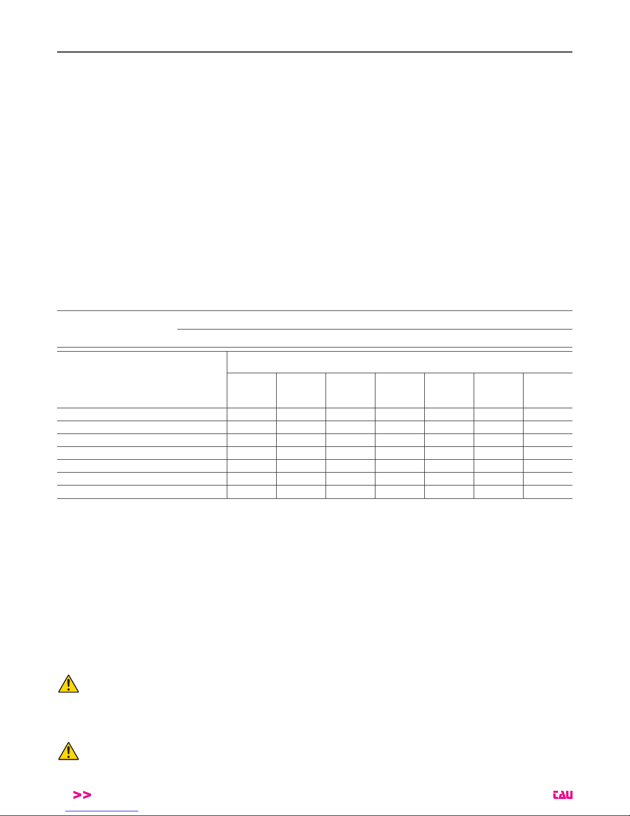
LUNGH. ASTA / BAR LENGHT / SCHRANKENBAUMLÄNGE
LONGUEUR LISSE / LONGITUD BARRA / COMPRIMENTO HASTE
4 ÷ 4,24
(m)
4,25 ÷ 4,74
(m)
4,75 ÷ 5,24
(m)
5,25 ÷ 5,74
(m)
5,75 ÷ 6,24
(m)
6,25 ÷ 6,74
(m)
6,75 ÷ 7
(m)
800AE + 800PG B+B B+C
1
C2+D - - - -
800AE + 800AT + 800ABTSE B
2
+D C+C C+C - - - -
800AE + 800AT + 800PG B+B B+C
1
C2+D D+D D+E
1
D+E
1
E+E
800AE + 800FPL + 800PG B+C
1
C+C D+D D2+E D+E
1
D+E
1
E+E
800AE + 800AT + 800GA2 B+B C+C D+D D
2
+E D2+E - -
800AE + 800FPL + 800GA2 B
2
+C C+C D2+E D2+E E+E - -
800AE5 + 800AT + 800PG8
*
B+A
2
B+B B2+C - - - -
1 La molla più robusta deve sempre essere installata dal lato passo carraio (1 g. 6) - The strongest spring should always be in-
stalled on the boom’s side (1 - pic. #6) - Die härtere Ausgleichsfeder muss neben den Schrankenbaum montiert werden (1 - Abb.
6) - Le ressort plus robuste doit être monté du côté de la lisse (1 - image 6) - El resorte más robusto tiene que ser puesto en el lado
del hasta (1 - imagen 6) - A mola mais forte deve ser instalada no lado da haste (1 - imagem 6).
2 La molla meno robusta deve sempre essere installata dal lato passo carraio (1 g. 6) - The weakest spring should always be installed
on the boom’s side (1 - pic. #6) - Die weniger harte Ausgleichsfeder muss neben den Schrankenbaum montiert werden (1 - Abb. 6) Le ressort moins robuste doit être monté du côté de la lisse (1 - image 6) - El resorte menos robusto tiene que ser puesto en el lado
del hasta (1 - imagen 6) - A mola menos forte deve ser instalada no lado da haste (1 - imagem 6).
*
ATTENZIONE: congurazione per asta da 4 a 5 m. 800AE5 non va assemblata con il giunto 800GI.
* ATTENTION: solution for boom lengths between 4 and 5 m - Do not assemble the boom 800AE5 with the joint 800GI.
* ACHTUNG: Konguration für Schrankenbaum von 4 bis 5 m. 800AE5 muss nicht mit dem 800GI Schrankenbaum-Verbindung zusammengebaut werden.
* ATTENTION: solution pour lisses de longueur entre 4 et 5 mètres. Ne pas assembler la lisse 800AE avec la jonction 800GI
* ATENCIÓN: conguración por asta de 4 a 5 m. 800AE5 no se debe ensamblar con la junta 800GI.
* ATENÇÃO: conguração para haste entre 4 a 5m. A haste 800AE5 não deve ser montada com a união 800GI.
Per lunghezze asta uguali o superiori a 5 m è obbligatorio l’uso dell’appoggio asta a terra sso o pensile.
For boom lengths equal or greater than 5 mt. it must use (mandatory) the ground boom support or the pendulum support
Bei einer Stangenlänge gleich oder über 5 m ist die Anwendung der Stangenauage am Boden fest oder hängend notwendig.
Pour lisses de 5 ou plus metrès de longueur, l’utilisation de la lyre de repos appui au sol ou suspendu est contraignante.
En el caso de que la longitud de la barra sea de 5 m o más, será obligatorio utilizar un soporte para la barra anclado al suelo o colgante.
Para comprimentos de haste iguais ou superiores a 5 m deve-se utilizar o suporte para haste xo no chão ou suspenso.
Per aste con passaggi utili superiori a 5 m è OBBLIGATORIO usare il rinforzo 800RA.
For bars with useful passage exceeding 5m, it is COMPULSORY to use the 800RA reinforcement.
Für Stangen mit Nenndurchlass über 5 m ist eine Verstärkung von 800RA UNBEDINGT notwendig.
Pour les barres de plus de 5 m d’envergure il est OBLIGATOIRE d’utiliser le renforcement 800RA.
Para varillas con pasaje útil superior a 5 m es OBLIGATORIO usar el refuerzo 800RA.
Para haste com largura de passagem útil superior a 5m é OBRIGATÓRIO aplicar o reforço 800RA.
Page 5

LUXE
5
ATTENZIONE: RISPETTO ALLA LUNGHEZZA NOMINALE DELL’ASTA, IL PASSAGGIO UTILE SI RIDUCE DI 353 mm (vedi g. 1).
ATTENTION: PASSAGE WIDTH EQUALS BAR LENGTH LESS 353 mm (see pic. #1).
ACHTUNG: TATSÄCHLICHE ABSPERRBREITE IST GLEICH BAUMLAENGE MINUS 353 mm (siehe Abb. 1).
AVERTISSEMENT: LE PASSAGE UTILE EST RÉDUIT DE 353 mm PAR RAPPORT À LA LONGUEUR NOMINALE DE LA LISSE (voir g. 1).
ATENCIÓN: EL PASO LIBRE ES IGUAL A LA LONGITUD DEL ASTA MENOS 353 mm (véase g. 1).
ATENÇÃO: A PASSAGEM UTIL É IGUAL AO CUMPRIMENTO DO HASTE MENOS 353 mm (ver g. 1).
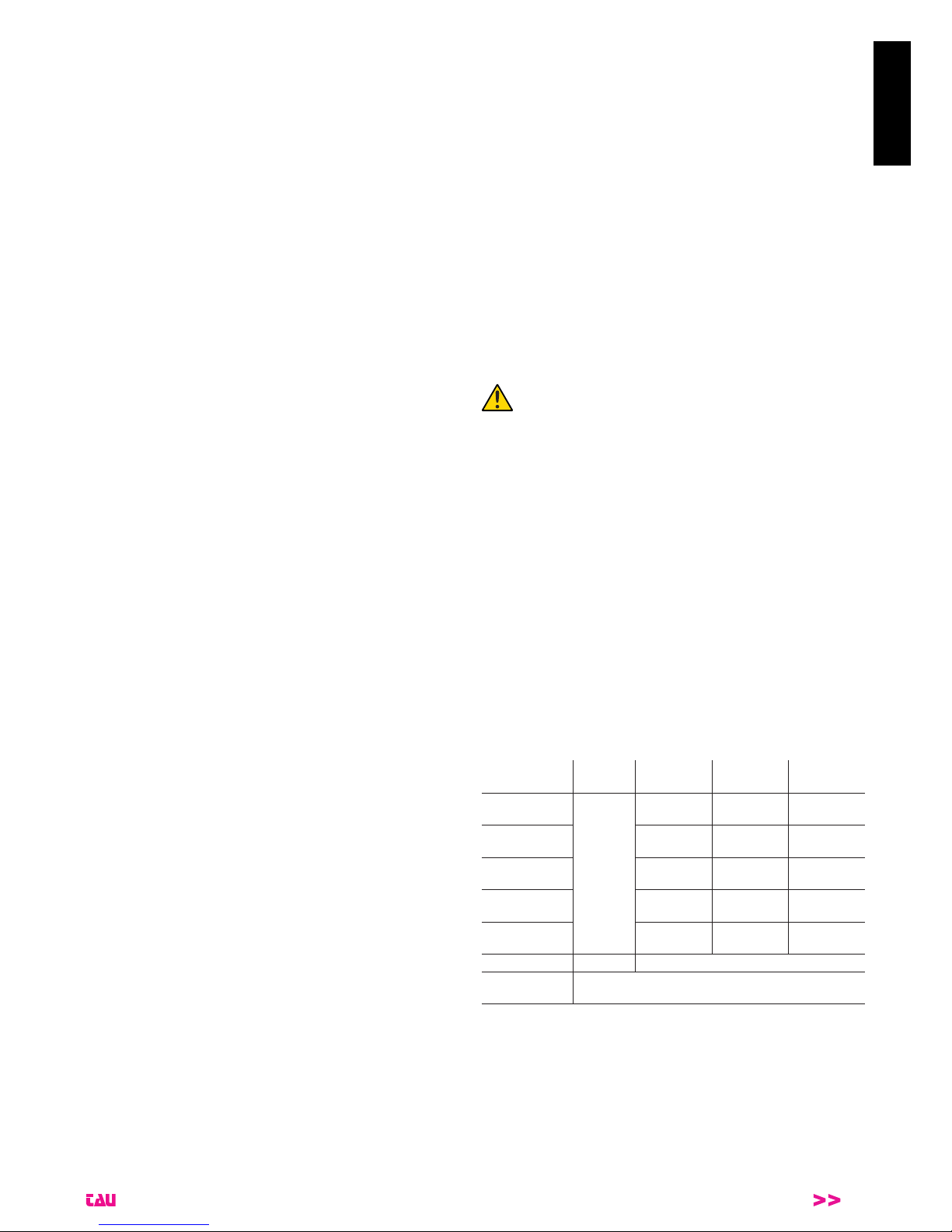
La trave forata permette di determinare carichi massimi differenti (in relazione alla lunghezza dell’asta e degli
accessori applicati ad essa) nelle varie posizioni (più ci si avvicina alla verticale, minore è il carico massimo).
MAX. LOAD
MIN. LOAD
The drilled beam allows to determine different maximum loads (in relation to the length of the bar and accessories applied) in the various positions (the nearer to the vertical, the lower the maximum load).
Der gebohrte Träger gestattet die festlegung anderer max. Lasten (in Abhängigkeit von der Länge der Stange
sowie dem angebrachten Zubehör) in verschiedenen Positionen (je näher der vertikalen, desto geringer ist die
max. Last).
Le faisceau perforé permet de déterminer les différentes charges maximales (par rapport à la longueur de la
barre et des accessoires qui lui sont appliqués) dans les différentes positions (plus on se rapproche de la verticale, plus la charge maximale diminue).
El travesaño perforado permite determinar cargas máximas diferentes (con relación a la longitud del asta y de
los accesorios aplicados en ella) en las distintas posiciones (más se acerca a la vertical menor será la carga
máxima).
O feixe de perfuração permite detreminar a carga máxima (em relação ao comprimento da haste e acessórios
aplicados) em várias posições (mais próximo do vertical, carga máxima menor).
Page 6

LUXE
6
DICHIARAZIONE DI INCORPORAZIONE DEL COSTRUTTORE
(ai sensi della Direttiva Europea 2006/42/CE AlI. II.B)
Fabbricante: TAU S.r.l.
Indirizzo: Via E. Fermi, 43
36066 Sandrigo (Vi)
ITALIA
Dichiara sotto la propria responsabilità che il prodotto: Attuatore elettromeccanico
realizzato per il movimento automatico di: Barriere stradali
per uso in ambiente: Generico
completo di: Centrale elettronica di controllo e radioricevente
Modello: LUXE
Tipo: LUXE - LUXE/I
Numero di serie: VEDI ETICHETTA ARGENTATA
Denominazione commerciale: BARRIERA AUTOMATICA
È realizzato per essere incorporato su una chiusura (barriera automatica) o per essere assemblato con altri dispositivi al ne di movi-
mentare una tale chiusura per costituire una macchine ai sensi della Direttiva Macchine 2006/42/CE.
Dichiara inoltre che questo prodotto è conforme ai requisiti essenziali di sicurezza delle seguenti ulteriori direttive CEE:
- 2014/35/EU Direttiva Bassa Tensione
- 2014/30/EU Direttiva Compatibilità Elettromagnetica
ed, ove richiesto, alla Direttiva:
- 2014/53/EU Apparecchiature Radio e apparecchiature terminali di telecomunicazione
Dichiara inoltre che non è consentito mettere in servizio il macchinario no a che la macchina in cui sarà incorporato o di cui diverrà
componente sia stata identicata e ne sia stata dichiarata la conformità alle condizioni della Direttiva 2006/42/CE.
Sono applicate le seguenti norme e speciche tecniche:
EN 61000-6-2; EN 61000-6-3; EN 60335-1; ETSI EN 301 489-1 V1.9.2; ETSI EN 301 489-3 V1.6.1;
EN 300 220-2 V2.4.1; EN 12453:2000; EN 12445:2000; EN 60335-2-103
Si impegna a trasmettere, su richiesta adeguatamente motivata delle autorità nazionali, informazioni pertinenti sulle quasi-macchine.
Sandrigo, 12/09/2017
Il Rappresentante Legale
_________________________________________
Loris Virgilio Danieli
Nome e indirizzo della persona autorizzata a costituire la documentazione tecnica pertinente:
Loris Virgilio Danieli - via E. Fermi, 43 - 3606 Sandrigo (Vi) Italia
ITALIANO
Page 7
LUXE
7
ITALIANO
AVVERTENZE PER L’INSTALLATORE
OBBLIGHI GENERALI PER LA SICUREZZA
1) Leggere attentamente le istruzioni prima di procedere
all’installazione, in quanto forniscono importanti indica-
zioni concernenti la sicurezza, l’installazione, l’uso e la
manutenzione. Una errata installazione o un errato uso
del prodotto può portare a gravi danni alle persone.
2) I materiali dell’imballaggio (plastica, polistirolo, ecc.) non de-
vono essere lasciati alla portata dei bambini in quanto poten-
ziali fonti di pericolo.
3) Conservare le istruzioni per riferimenti futuri.
4) Questo prodotto è stato progettato e costruito esclusivamen-
te per l’utilizzo indicato in questa documentazione. Qualsiasi
altro utilizzo non espressamente indicato potrebbe pregiudi-
care l’integrità del prodotto e/o rappresentare fonte di perico-
lo.
5) TAU Srl declina qualsiasi responsabilità derivata dall’uso im-
proprio o diverso da quello per cui l’automatismo è destinato.
6) Non installare l’apparecchio in atmosfera esplosiva: la pre-
senza di gas o fumi inammabili costituisce un grave pericolo
per la sicurezza.
7) Gli elementi costruttivi meccanici devono essere in accordo
con quanto stabilito dalle Norme EN 12604 e EN 12605. Per
i Paesi extra-CEE, oltre ai riferimenti normativi nazionali, per
ottenere un livello di sicurezza adeguato, devono essere se-
guite le Norme sopra riportate.
8) TAU Srl non è responsabile dell’inosservanza della Buona
Tecnica nella costruzione delle chiusure da motorizzare, non-
ché delle deformazioni che dovessero intervenire nell’utiliz-
zo.
9) L’installazione deve essere effettuata nell’osservanza delle
Norme EN 12453 e EN 12445. Per i Paesi extra-CEE, oltre
ai riferimenti normativi nazionali, per ottenere un livello di si-
curezza adeguato, devono essere seguite le Norme sopra
riportate.
10) Prima di effettuare qualsiasi intervento sull’impianto, togliere
l’alimentazione elettrica.
11) Prevedere sulla rete di alimentazione dell’automazione un
interruttore onnipolare con distanza d’apertura dei contatti
uguale o superiore a 3 mm. È consigliabile l’uso di un ma-
gnetotermico da 6A con interruzione onnipolare.
12) Vericare che a monte dell’impianto vi sia un interruttore dif-
ferenziale con soglia da 0,03 A.
13) Vericare che l’impianto di terra sia realizzato a regola d’arte
e collegarvi le parti metalliche della chiusura.
14) L’automazione dispone di una sicurezza intrinseca anti-
schiacciamento costituita da un controllo di coppia. E’ co-
munque necessario vericarne la soglia di intervento secon-
do quanto previsto dalle Norme indicate al punto 9.
15) I dispositivi di sicurezza (norma EN 12978) permettono di
proteggere eventuali aree di pericolo da Rischi meccanici di
movimento, come ad Es. schiacciamento, convogliamento,
cesoiamento.
16) Per ogni impianto è consigliato l’utilizzo di almeno una se-
gnalazione luminosa (900T-LED, 800LA, 800LL) nonché di
un cartello di segnalazione ssato adeguatamente sulla strut-
tura dell’insso, oltre ai dispositivi citati al punto 15.
17) TAU Srl declina ogni responsabilità ai ni della sicurezza e
del buon funzionamento dell’automazione, in caso vengano
utilizzati componenti dell’impianto non di produzione TAU.
18) Per la manutenzione utilizzare esclusivamente parti originali
TAU.
19) Non eseguire alcuna modica sui componenti facenti parte
del sistema d’automazione.
20) L’installatore deve fornire tutte le informazioni relative al
funzionamento manuale del sistema in caso di emergenza
e consegnare all’Utente utilizzatore dell’impianto la “Guida
Utente” allegata al prodotto.
21) Non permettere ai bambini o persone di sostare nelle vicinan-
ze del prodotto durante il funzionamento.
22) Tenere fuori dalla portata dei bambini radiocomandi o qual-
siasi altro datore di impulso, per evitare che l’automazione
possa essere azionata involontariamente.
23) Il transito deve avvenire solo ad automazione ferma.
24) L’Utente utilizzatore deve astenersi da qualsiasi tentativo di
riparazione o d’intervento diretto e rivolgersi solo a personale
qualicato.
25) Non lavare l’automazione con idropulitrice.
26) Manutenzione: effettuare almeno semestralmente la verica
funzionale dell’impianto, con particolare attenzione all’efcienza dei dispositivi di sicurezza (compresa, ove previsto, la
forza di spinta dell’operatore) e di sblocco.
27) Tutto quello che non è previsto espressamente in queste
istruzioni non è permesso.
1_ CONDIZIONI DI UTILIZZO
La barriera automatica LUXE è stata progettata per l’utilizzo in
parcheggi privati o pubblici, in aree residenziali o in zone ad alta
intensità di passaggio.
2_ MISURE DI INGOMBRO
Nella g. 1 sono indicate le principali misure di ingombro per la
barriera; in g. 2 sono riportate le dimensioni della contropiastra
di fondazione.
3_ INSTALLAZIONE
L’installazione deve essere effettuata da personale
qualicato ed esperto e nel pieno rispetto delle normative vigenti.
3.1_ Veriche preliminari
Per la sicurezza e per un corretto funzionamento dell’automazione,
vericare l’esistenza dei seguenti requisiti:
• La sbarra nel suo movimento non deve assolutamente incon-
trare ostacoli o cavi aerei di tensione.
• Le caratteristiche del terreno devono garantire una sufciente
tenuta del plinto di fondazione.
• Prevedere adeguato dispositivo di disconnesione onnipolare,
con distanza maggiore di 3 mm tra i contatti, a sezionamento
dell’alimentazione;
• Nella zona di scavo del plinto non devono essere presenti tu-
bazioni o cavi elettrici.
• Se il corpo barriera si trova esposto al passaggio di veicoli,
possibilmente prevedere adeguate protezioni contro urti acci-
dentali.
• Vericare l’esistenza di una efciente presa di terra per il colle-
gamento dell’armadio.
• Predisporre adeguate tubazioni e canaline per il passaggio dei
cavi elettrici garantendone la protezione contro il danneggia-
mento meccanico.
3.2_ Tipologia cavi
Collegamento
Tipologia
cavo
L cavo
1 < 10 m
L cavo
10 < 20 m
L cavo
20 < 30 m
Alimentazione
230 V
FROR
CEI 20-22
CEI EN
50267-2-1
3 x 1,5 mm² 3 x 2,5 mm² 3 x 4 mm²
Trasmettitori
fotocellule
2 x 0,5 mm² 2 x 0,5 mm² -
Ricevitori
fotocellule
4 x 0,5 mm² 4 x 0,5 mm² -
Alimentazione
accessori 24 V
2 x 0,5 mm² 2 x 1 mm² -
Dispositivi di
comando
2 x 0,5 mm² 2 x 0,5 mm² 2 x 0,5 mm²
Antenna RG58 cavo fornito in dotazione
Rilevatore mas-
se metalliche
vedi istruzioni relative
NOTA: Qualora i cavi abbiano lunghezza diversa rispetto a
quanto previsto in tabella, si determini la sezione dei cavi
sulla base dell’effettivo assorbimento dei dispositivi collegati e secondo le prescrizioni indicate dalla normativa CEI EN
60204-1.
Per i collegamenti che prevedano più carichi sulla stessa linea (sequenziali), il dimensionamento a tabella deve essere
riconsiderato sulla base degli assorbimenti e delle distanze
effettivi. Per i collegamenti di prodotti non contemplati in questo manuale fa fede la documentazione allegata ai prodotti
stessi.
Page 8

LUXE
8
3.3_ Impianto tipo (g. 11)
1 Armadio Luxe
2 Quadro di comando
3 Asta in alluminio
4 Striscia led
5 Giunto per asta
6 Indicatore luminoso a led
7 Antenna
8 Colonnina per fotocellule
9 Fotocellule
10 Supporto laterale per fotocellula
11 Appoggio asta (sso)
12 Rilevatore masse metalliche
3.4_ Preparazione base automazione
Murare la piastra di fondazione in modo da permettere
un agevole accesso allo sportello della barriera ed alla
maniglia di sblocco.
Creare una soletta (A g. 3) di forma rettangolare e di adeguate
dimensioni prevedendo i fori per l’uscita dei cavi. Usare possibil-
mente la contropiastra di fondazione (B g. 3), con i 4 tiranti in dotazione da annegare nel cemento; oppure, a soletta nita, ssare
l’armadio della barriera direttamente con 4 tasselli da fondazione
M10x120 (C g. 3). Lo spessore della soletta deve essere di almeno 10 cm, ricordando che può essere aumentato se le condizioni
del terreno lo richiedono.
3.5_ Installazione del gruppo barriera
La barriera priva di asta e di molle va ora posizionata procedendo
come descritto di seguito:
- togliere dadi e rondelle dalle viti sporgenti, posizionare l’ar-
madio sulla base e ssarlo. Si controlli ora l’assoluta stabilità
dell’ancoraggio e si operi, se necessario, in tal senso.
Nota: è consigliabile installare l’armadio con la porta rivolta verso
il lato più agevole.
- Aprire la porta con l’apposita chiave e rimuoverla.
Normalmente “LUXE” viene consegnata DESTRA (DX), con il porta asta in posizione orizzontale. Per barriera destra (DX) si intende
con l’armadio posizionato a destra visto dall’interno del passaggio
(convenzionalmente, lo sportello va all’interno).Se ci dovesse essere l’esigenza di trasformarla SINISTRA (SX), occorre invertire il
senso di apertura dell’asta.
Operare come segue:
1_ dopo aver rimosso le viti con occhiello e gli anelli elastici,
estrarre i perni e riposizionarli, simmetricamente, dal lato opposto della trave forata (g. 4A), quindi fermarli con gli anelli
elastici e riavvitare le viti;
2_ dopo aver asportato la vite e la rondella di bloccaggio, rimuove-
re la leva di bilanciamento asta. Nel gruppo di sostegno molle,
invertire la posizione del perno (1 g. 4B), quindi ruotare tutto
il blocco di 180° (rispetto alla posizione precedente) e ssarlo
nuovamente all’albero motore con bullone e rondella (g. 4C);
3_ una volta modicato il senso della barriera è necessario inver-
tire i collegamenti del motore (vedi istruzioni K206MA).
La trave forata permette di determinare carichi massimi
differenti (in relazione alla lunghezza dell’asta e degli
accessori applicati ad essa) nelle varie posizioni (più ci
si avvicina alla verticale, minore è il carico massimo).
Una volta modicato il senso della barriera, la collocazione dei dispositivi è invertita.
Nel caso si debba modicare la barriera da SX a DX, le operazioni
da eseguire sono le stesse.
3.6_ Fissaggio asta, montaggio molle e bilanciamento asta
Ogni operazione va eseguita in assenza di alimentazione.
Dopo aver sbloccato l’automazione (vedi capitolo “Sblocco manuale”), operare come segue:
1_ servendosi di un appoggio, avvicinare l’asta in orizzontale (to-
talmente assemblata con tutti gli accessori previsti) al porta
asta e ssarla con la staffa ad omega, per mezzo delle viti in
dotazione (g. 5A);
Nota: l’asta deve essere inserita per tutta la lunghezza della
staffa ad omega.
2_ una volta ssata la staffa ad omega passare, se presente, il
cavo dei led (dopo aver tolto il tappo di protezione) attraverso
il foro predisposto sull’armadio (fare riferimento alla gura 9
per portare il cavo alla centrale di comando), quindi montare la
copertura e ssarla con le viti in dotazione (g. 5B);
3_ portare ora l’asta in posizione verticale e bloccare il motoridut-
tore (vedi capitolo “Sblocco manuale”).
Procedere quindi al montaggio delle molle agganciadole alle viti
con occhiello e ruotarle manualmente nel senso indicato dalla freccia per eseguire un primo precarico (g. 5C).
Procedere ora con il bilanciamento dell’asta.
Prima di bilanciare l’asta, vericare, con la tabella di pag.
4, la congruenza tra molla scelta, accessori da applicare
e luce passaggio. Il corretto bilanciamento è fondamentale per un buon funzionamento della barriera.
Questa operazione va eseguita solo quando l’asta è montata
in modo denitivo e con tutti gli eventuali accessori.
g. 6: agire sullo sblocco manuale (vedi capitolo “Sblocco ma-
nuale”) mantenendo una distanza di sicurezza. L’asta deve
portarsi da sola a 30°, altrimenti caricare/scaricare le molle
(se l’asta tende ad alzarsi oltre i 30° le molle vanno scaricate, ossia bisogna ruotarle manualmente in senso antiorario,
viceversa, se non raggiunge i 30°, le molle vanno caricate,
ossia ruotate manualmente in senso orario). Abbassare l’asta e rilasciarla, controllare che abbia raggiunto i 30°.
Per un buon funzionamento della barriera, all’atto del
carico/scarico delle molle, mantenere la stessa sporgenza delle viti con occhiello (g. 5C).
Procedere con i collegamenti elettrici al quadro comando (vedi capitolo collegamenti elettrici).
Nota: vericare il corretto funzionamento della molla.
ATTENZIONE! Per un corretto funzionamento, con asta
completamentamente aperta le molle devono sempre
mantenere un minimo di carico.
3.7_ Sblocco manuale
ATTENZIONE! Lo sblocco e qualsiasi altra operazione
manuale vanno eseguite solo con asta montata. Si fa
assoluto divieto di azionare la barriera priva di asta.
1_ Inserire la chiave nella serratura della maniglia sul retro dell’ar-
madio e ruotarla di 180° in senso antiorario (g. 7A);
2_ estrarre la maniglia e ruotarla di 90° in senso antiorario no a
sbloccare l’asta (se inizialmente sembra resistere, imprimere
alla maniglia maggior forza, non si provocano rotture di alcun
tipo), g. 7B.
A sblocco avvenuto, l’asta deve automaticamente portarsi
nella posizione di equilibrio (30° ca.).
ATTENZIONE! L’operazione di sblocco può rappresentare un possibile pericolo per l’utente quando, per un
qualsiasi motivo (asta mal ssata alla sua sede durante
il montaggio, asta divelta o spezzata da un incidente
etc.) le molle in tensione non garantiscono più il bilanciamento!
Esse possono provocare perciò una brusca rotazione
dell’attacco asta e/o dell’asta stessa.
3.8_ Regolazione dei necorsa
Normalmente la barriera viene fornita con i necorsa già regolati
per permettere il movimento ideale dell’asta.
In caso di errato livellamento della piastra da cementare, I’asta
potrebbe non risultare perfettamente orizzontale o verticale con un
conseguente cattivo risultato estetico dell’installazione.
Per eventualmente correggere la posizione verticale (=apertura),
chiudere la sbarra, aprire la porta e ruotare il tampone libero (1 g.
8) in senso orario (per aumentare la corsa dell’asta) o antiorario
(per diminuire la corsa dell’asta).
ITALIANO
Page 9
LUXE
9
Analogamente, per correggere la posizione orizzontale (= chiusura), aprire la sbarra e regolare il tampone libero (2 g. 8).
Dopo le veriche o le regolazioni di apertura e chiusura dell’asta,
serrare denitivamente i controdadi di ssaggio sotto i tamponi.
Ogni qualvolta viene modicata la posizione dei necorsa meccanici, è necessario ripetere la procedura di
memorizzazione sulla scheda di comando (vedi istruzioni K206MA).
A regolazione ultimata, eseguire la procedura di memorizzazione sulla scheda di comando (vedi istruzioni K206MA), vericando, dalla seconda manovra in automatico (la prima serve
alla centrale di comando per acquisire i nuovi necorsa) la
corretta posizione dell’asta, eventualmente ripetere la procedura.
Al completamento di tutte le operazioni di installazione meccanica
ed elettronica ssare il coperchio dell’armadio, riposizionare la porta e chiuderla con la chiave.
3.9_ Collegamenti elettrici
Ciascun dispositivo, alimentazione inclusa, deve essere installato
a regola d’arte e comunque secondo le normative vigenti. Separare i cavi di potenza dai cavi di comando, specialmente se i percorsi sono lunghi (oltre 50 mt). Per la sezione dei cavi (antenna
esclusa), la TAU consiglia: alimentazione 1,5 mm², altri cavi 0,5
mm² e comunque di attenersi alla norma IEC 364 e alle norme di
installazione vigenti nel proprio Paese. Per accedere alla scheda
comando togliere il coperchio dell’armadio (1 g. 9) dopo aver rimosso le viti di bloccaggio e le rondelle. Ora è possibile accedere
alle connessioni.
N.B. I cablaggi interni sono già effettuati e collaudati. Occorre
provvedere al collegamento dell’alimentazione, della fotocellula esterna, dei led e di eventuali comandi remoti e alla programmazione della scheda.
3.10_ Ultime operazioni
Provata l’efcacia di ogni singolo dispositivo preposto al comando
o al controllo della barriera, assicurarsi del ripristino dell’integrità
della stessa prima di renderla al servizio degli utenti.
Sistemare quindi in un luogo di facile leggibilità cartelli indicanti la
presenza della barriera automatica.
4_ USO
La barriera é stata concepita solo ed unicamente per limitare il usso di veicoli e/o persone in accessi protetti tramite l’impedimento
esercitato dall’asta. In caso di mancanza di alimentazione, è previsto, a richiesta, il funzionamento con batteria a secco 12V.
Si ricorda inoltre che si è in presenza di un apparecchio elettrico, e
come tale va avvicinato e usato con circospezione e prudenza. In
particolare raccomandiamo di:
• non toccare l’apparecchio con mani bagnate e/o piedi nudi o bagnati;
• non consentire il funzionamento automatico o semiautomatico
in presenza di malfunzionamenti certi o sospetti;
• non tirare il cavo di alimentazione per scollegare l’apparecchio;
• non lasciare che bambini o incapaci dispongano delle chiavi dell’armadio e dei comandi (anche via radio) anche se solo per diletto;
• non comandare la barriera quando non si ha la completa visibilità della barriera stessa;
• non entrare nel raggio di azione della barriera mentre è in mo-
vimento, ma attenderne l’arresto;
• non appoggiarsi all’armadio o all’asta per nessun motivo, neanche a barriera inattiva e comunque non sostare nel raggio di
azione della barriera;
• non lasciare che bambini o animali giochino nei pressi della
barriera;
• non adoperare la barriera per usi diversi da quello previsto (es.
sollevamento pesi o persone). Il costruttore non assumerà alcuna responsabilità per danni derivanti da tali comportamenti;
• provvedere alla manutenzione periodica da parte di personale
specializzato;
• in caso di guasto togliere l’alimentazione. Procedere alla ge-
stione manuale solo se sicura. Astenersi dall’intervenire e rivol-
gersi esclusivamente a personale qualicato della casa madre
o da essa autorizzato. Assicurarsi in ogni caso che i pezzi di
ricambio siano originali per non compromettere la sicurezza
della barriera.
5_ MANUTENZIONE
Da effettuare solamente da parte di personale specializzato dopo
aver tolto I’alimentazione elettrica al motore.
Ogni 100.000 manovre complete vericare:
- l’ingrassaggio delle molle;
- il bilanciamento dell’asta (vedi capitolo “Fissaggio asta, montaggio molle e bilanciamento asta”);
- l’efcienza delle forze;
- lo stato della batteria, se presente;
- l’efcienza dei dispositivi di protezione e di sicurezza;
- I’usura delle battute di fermo meccanico e la regolazione dei
necorsa (vedi capitolo “Regolazione necorsa”).
La manutenzione sopra descritta è vitale per II corretto funzionamento del prodotto nel tempo.
Generalita’
La barriera non deve poter essere comandata da terzi durante
questa fase; togliere quindi l’alimentazione di rete (e la batteria se
presente).
• Sbloccare prima l’asta per agevolare l’operazione.
Ingrassaggio
1_ Aprire la porta della barriera;
2_ Dare grasso agli occhielli delle viti delle molle di bilanciamento (1
g. 10) e allo snodo sferico sulla leva di bilanciamento (3 g. 10);
3_ Ingrassare il punto di contatto tra l’eccentrico dello sblocco ma-
nuale e la leva di sblocco (2 g. 10).
4_ Tenersi lontani da ingranaggi o da parti meccaniche di possibi-
le movimento.
FREQUENZA: ogni 100.000 manovre o 6 mesi, pena la decadenza della garanzia.
N.B.: Si raccomanda esclusivamente l’impiego di grasso al
sapone di calcio complesso per alti carichi.
Bilanciamento asta
Controllare il bilanciamento dell’asta ripetendo le manovre descrit-
te nella sezione “Fissaggio asta, montaggio molle e bilanciamento”. Tale operazione è basilare per il corretto funzionamento e la
durata della barriera. Se necessario, aumentare il precarico molle
per compensare l’usura della stessa. Nel caso in cui si renda ne-
cessaria la sostituzione delle molle, si veda più avanti il paragrafo
“Manutenzione straordinaria e riparazioni”.
FREQUENZA: ogni 100.000 manovre o 6 mesi, pena la decaden-
za della garanzia.
Controllo efcienza limitazione delle forze
Vericare la corrispondenza tra comportamento reale e comportamento stabilito in fase di installazione.
FREQUENZA: ogni 100.000 manovre o 6 mesi, pena la decaden-
za della garanzia.
Controllo della batteria 12v cc
Utilizzando il tester per le batterie vericare il grado di carica della
batteria. In caso di sostituzione, rimpiazzare l’unità inutilizzabile
con una originale avendo cura di non abbandonarla nell’ambiente.
FREQUENZA: ogni 100.000 manovre o 6 mesi, pena la decaden-
za della garanzia.
Controllo dei dispositivi di protezione e di sicurezza rimanenti
Fotocellule: possono agire sia in apertura che in chiusura; controllare la programmazione del dip switch. Pulire l’involucro esterno.
Vericare che le seguenti speciche siano rispettate:
• Il lampeggiante sia funzionante e ben visibile.
• L’adesivo di segnalazione pericolo ssato sulla porta sia ben
attaccato e visibile.
• L’adesivo di segnalazione pericolo ssato nella parte dietro
della barriera sia ben attaccato e visibile. In caso di mancata
rispondenza di tali dispositivi ai criteri esposti, ripristinare la originaria efcienza o, se impossibile, operare una loro sostituzio-
ne.
FREQUENZA: ogni 6 mesi, pena la decadenza della garanzia.
ITALIANO
Page 10
LUXE
10
6_ MANUTENZIONE STRAORDINARIA E RIPARAZIONI
ATTENZIONE: DOPO LE PRIME 2000 MANOVRE ESEGUIRE
UNA NUOVA PROCEDURA DI BILANCIAMENTO DELL’ASTA.
Nel caso in cui si renda necessaria una riparazione di non banale
esecuzione o una sostituzione di pezzi di organi elettromeccanici,
si raccomanda la rimozione del blocco in cui l’operazione è localizzabile (scheda di comando, blocco del motoriduttore) per poter
cosi permettere una riparazione in ofcina dalla casa madre o da
tecnici da essa autorizzati. Diversamente, la sicurezza e l’afdabilità della barriera possono venir meno (cosi come il contratto di
garanzia).
In caso di utilizzo della barriera in ambiente salso o fortemente contaminato da reagenti chimici corrosivi, la
frequenza dei controlli manutentivi si intende aumentata in ragione dell’incrementato logorio ambientale; in
questo caso si raccomanda anche un’ispezione all’integrità dell’armadio esterno metallico.
7_ DIAGNOSI DELLE CAUSE DI GUASTO PIÙ COMUNE
In questo paragrafo verranno brevemente trattare le cause più probabili dei guasti più comuni, in modo da favorire il pronto recupero
della barriera.
La casistica riportata non è in ogni caso completa (sia dal punto di
vista delle cause, che dal punto di vista dei guasti).
a_ La barriera è bloccata (aperta, chiusa o semiaperta):
1_ mancanza di alimentazione;
2_ comandi non efcienti;
3_ fusibile di alimentazione bruciato;
4_ fotocellule (abilitate anche in apertura) attive perché non alline-
ate e/o perché ostacolate (erba, ecc);
b_ la barriera continua ad aprirsi e chiudersi;
1_ controllare falsi contatti dei pulsanti dei telecomandi e dei selet-
tori a chiave che restano inseriti;
c_ la barriera resta aperta;
1_ le fotocellule sono attive perchè non allineate e/o perché spor-
che (fango,ecc) e/o ostacolate (erba, ecc);
d_ la barriera fatica ad aprirsi;
1_ la molla di bilanciamento asta è starata;
e_ la barriera si alza/abbassa più del limite previsto;
1_ i necorsa meccanici sono da registrare (vedi capitolo “REGO-
LAZIONE FINECORSA”).
8_ DISMISSIONE
Quando la barriera giunge alla ne del proprio servizio si consiglia
di rimuoverla per poi riciclarne i materiali riutilizzabili. Prestare attenzione a quanto sancito da regolamenti e leggi locali e/o nazionali. Si prega di porre attenzione al riciclo dei seguenti componenti:
• armadio verniciato con vernice epossidica
• cupolino lampeggiante in metacrilato
• scatola scheda comando in ABS
• schede elettroniche
• batteria 12V cc a secco (piombo acido)
• grasso al litio interno al riduttore
• connessioni e protezioni minori in gomma e/o plastica.
RISPETTARE L’AMBIENTE!
AVERTENZE PER LO SMONTAGGIO: le operazioni di rimozione
della barriera devono rispettare criteri di sicurezza: disconnettere
quindi per prima cosa la barriera dalle rete elettrica. Allentare (non
completamente) i tiranti di regolazione delle molle di bilanciamento
per poter togliere l’asta più comodamente e con maggior tranquillità. Svitare quindi le viti di ancoraggio sul fondo dell’armadio per
poterlo maneggiare a piacimento.
9_ TRASPORTO
La barriera è imballata in uno scatolone di cartone separatamente
all’asta, che può essere acquistata su richiesta.
Si raccomanda cura e perizia in ogni fase di movimentazione. Per il
sollevamento e lo spostamento si consiglia l’uso di carrelli manuali
o motorizzati. Lo stoccaggio, anche temporaneo, deve avvenire
verticalmente rispettando il verso indicato sull’imballo e tenendo
presente che il baricentro alto conferisce instabilità.
L’asta deve essere stoccata avendo cura di evitare sporgenze o
carichi che possano danneggiarla. Una volta privati dell’imballo
assicurarsi dell’integrità del prodotto. Non abbandonare gli imballi,
bensì riciclarli secondo le normative vigenti nel paese di impiego.
ATTENZIONE: non lasciare che i bambini maneggino
i materiali di imballo per evitare soffocamenti e altri
pericoli di sorta.
GARANZIA: CONDIZIONI GENERALI
La garanzia della TAU ha durata di 24 mesi dalla data di acquisto
dei prodotti (fa fede il documento scale di vendita, scontrino o
fattura).
La garanzia comprende la riparazione con sostituzione gratuita
(franco sede TAU: spese di imballo e di trasporto sono a carico
del cliente) delle parti che presentano difetti di lavorazione o vizi di
materiale riconosciuti dalla TAU.
In caso di intervento a domicilio, anche nel periodo coperto da garanzia, l’utente è tenuto a corrispondere il “Diritto sso di chiamata”
per spese di trasferimento a domicilio, più manodopera.
La garanzia decade nei seguenti casi:
• Qualora il guasto sia determinato da un impianto non es-
eguito secondo le istruzioni fornite dall’azienda all’interno
di ogni confezione.
• Qualora non siano stati impiegati tutti componenti originali
TAU per l’installazione dell’automatismo.
• Qualora i danni siano causati da calamità naturali, man-
omissioni, sovraccarico di tensione, alimentazione non
corretta, riparazioni improprie, errata installazione, o altre
cause non imputabili alla TAU.
• Qualora non siano state effettuate le manutenzioni periodi-
che da parte di un tecnico specializzato secondo le istruzioni fornite dall’azienda all’interno di ogni confezione.
• Usura dei componenti.
La riparazione o la sostituzione dei pezzi durante il periodo di garanzia non comporta un prolungamento del termine di scadenza
della garanzia stessa.
In caso di utilizzo industriale o professionale oppure in caso di impiego simile, tale garanzia ha validità 12 mesi.
ITALIANO
Page 11

LUXE
11
MANUFACTURER’S DECLARATION OF INCORPORATION
(in accordance with European Directive 2006/42/EC App. II.B)
Manufacturer: TAU S.r.l.
Address: Via E. Fermi, 43
36066 Sandrigo (Vi)
ITA LY
Declares under its sole responsibility, that the product: Electromechanical actuator
designed for automatic movement of: Road Barriers
for use in a: General environment
complete with: Electronic control unit and radioreceiver
Model: LUXE
Type: LUXE - LUXE/I
Serial number: SEE SILVER LABEL
Commercial name: AUTOMATIC BARRIER
Has been produced for incorporation on an access point (automatic barrier) of for assembly with other devices used to move such an
access point, to constitute a machine in accordance with the Machinery Directive 2006/42/EC.
Also declares that this product complies with the essential safety requirements of the following EEC directives:
- 2014/35/EU Low Voltage Directive
- 2014/30/EU Electromagnetic Compatibility Directive
and, where required, with the Directive:
- 2014/53/EU Radio equipment and telecommunications terminal equipment
Also declares that it is not permitted to start up the machine until the machine in which it is incorporated or of which it will be a com-
ponent has been identied with the relative declaration of conformity with the provisions of Directive 2006/42/EC.
The following standards and technical specications are applied:
EN 61000-6-2; EN 61000-6-3; EN 60335-1; ETSI EN 301 489-1 V1.9.2; ETSI EN 301 489-3 V1.6.1;
EN 300 220-2 V2.4.1; EN 12453:2000; EN 12445:2000; EN 60335-2-103.
The manufacturer undertakes to provide, on sufciently motivated request by national authorities, all information pertinent to the quasi-
machinery.
Sandrigo, 12/09/2017
Legal Representative
_________________________________________
Loris Virgilio Danieli
Name and address of person authorised to draw up all pertinent technical documentation:
Loris Virgilio Danieli - via E. Fermi, 43 - 3606 Sandrigo (Vi) Italia
ENGLISH
Page 12
LUXE
12
INSTALLATION WARNINGS
GENERAL SAFETY REQUIREMENTS
1) Carefully read all instructions before installation, as they
provide important instructions regarding the safety, installation, operation and maintenance. Incorrect installation or use of the product may lead to serious physical
injury.
2) Never leave packaging materials (plastic, polystyrene etc.)
within the reach of children as they constitute a potential haz-
ard.
3) Keep the instructions in a safe place for future consultation.
4) This product has been designed and constructed exclusively
for the use specied in this documentation. Any other use not
specied herein may impair product integrity and/or constitute a hazard.
5) TAU Srl declines all liability for improper use or use other than
as specied for this automation.
6) Do not install the unit in an explosive environment: the presence of either gas or ammable fumes is a serious safety
risk.
7) The mechanical elements must comply with the requirements
as stated in the standards EN 12604 and EN 12605. For non
European member states, in addition to the national reference standards, the above-mentioned standards must be observed to ensure an adequate level of safety.
8) TAU Srl is not responsible for failure to observe Good Practice in construction of the gates/doors to be power-operated,
nor any deformations occurring during use.
9) Installation must be performed in compliance with the standards EN 12453 and EN 12445. For non European member
states, in addition to the national reference standards, the
above-mentioned standards must be observed to ensure an
adequate level of safety.
10) Before performing any operations on the system, disconnect
from the mains and detach the batteries.
11) On the automation power line, install a device for disconnection from the power mains with a gap between contacts equal
to or greater than 3 mm. Use of a 6A thermal magnetic circuit
breaker with multi-pole switch is recommended.
12) Check upline of the system that there is a residual current
circuit breaker with a threshold of 0.03 A.
13) Ensure that the earthing system is to professional standards
and connected to the metal section of the gate/door.
14) The automation is equipped with an intrinsic anti-crushing
safety device comprising a torque control. The trip threshold must in all cases be checked as stated in the standards
specied in point 9.
15) The safety devices (standard EN 12978) enable the protection of danger areas from risks associated with mechani-
cal movements such as crushing, dragging and shearing.
16) The use of at least one luminous indicator is recommended
for each system (900T-LED, 800LA, 800LL), as well as a
warning notice xed suitably to the frame structure, in addition to the devices specied in point 15.
17) TAU declines all liability for the safety and efcient operation
of the automation in the event of using system components
not produced by TAU.
18) For maintenance, use exclusively original TAU parts.
19) Never modify components that are part of the automation
system.
20) The installer must provide all information regarding manual
operation of the system in the event of an emergency and
supply the system User with the “User Guide” enclosed with
the product.
21) Never allow children or other persons to stay in the vicinity of
the product during operation.
22) Keep all radio controls or other pulse supplier device out of
the reach of children to prevent inadvertent activation of the
automation.
23) Transit should only occur with the automation stationary.
24) The user must never attempt to repair or intervene directly on
the product; always contact qualied personnel for assistance.
25) It is strictly forbidden to use high pressure water cleaners or
jets of water in general to clean the automation.
26) Maintenance: at least every six months, make a general
check of the system, with special reference to the efciency
of the safety devices (including, when envisaged, the operator thrust force) and release mechanisms.
27) All actions not expressly envisaged in these instructions
are strictly prohibited.
1_ CONDITIONS OF USE
The LUXE automatic barrier has been designed for use in private
or public car parks, residential areas or areas of intense trafc.
2_ OVERALL DIMENSIONS
The main dimensions of the barrier are indicated in pic. # 1; pic. #
2 illustrates the dimensions of the foundation base plate.
3_ INSTALLATION
Installation must be carried out by skilled and qualied
personnel in compliance with the regulations in force.
3.1_ Preliminary checks
For the safety and correct operation of the automation, check the
following:
• While moving the barrier must meet no obstacle or aerial power
cables.;
• The characteristics of the ground must guarantee sufcient
hold for the foundation plinth;
• A suitable omnipolar circuit breaker with a distance greater
than 3mm between contacts must be provided to isolate the
supply;
• There must be no pipes or electrical cables in the area where
the plinth foundation is excavated;
• If the barrier is exposed to passing vehicles, provide suitable
protection to avoid accidental collisions;
• Check there is an efcient earthing device to connect the cabi-
net;
• There must be suitable piping and tracks for electrical cables to
guarantee they are not damaged.
3.2_ Cables typology
Connection
Type of
cable
Cable l.
1 < 10 m
Cable l.
10 < 20 m
Cable l.
20 < 30 m
230v supply
FROR
CEI 20-22
CEI EN
50267-2-1
3 x 1,5 mm² 3 x 2,5 mm² 3 x 4 mm²
Photocell trans-
mitters
2 x 0,5 mm² 2 x 0,5 mm² -
Photocell
receivers
4 x 0,5 mm² 4 x 0,5 mm² -
Accessory
24v power
supply
2 x 0,5 mm² 2 x 1 mm² -
Control devices 2 x 0,5 mm² 2 x 0,5 mm² 2 x 0,5 mm²
Aerial RG58 Cable supplied
Metal mass
sensor
See relative instructions
NOTE: If the length of the cables is not as stated in the table, determine the cable section on the basis of the real draw
of the connected devices and in compliance with the IEC EN
60204-1 Standard.
As to connections with numerous loads on the same line (in
sequence), dimensions must be recalculated on the basis of
the real draw and distance. As to the connection of any products not dealt with in this manual, the documents attached to
the products themselves must be consulted.
ENGLISH
Page 13
LUXE
13
ENGLISH
3.3_ Typical system (pic. # 11)
1 Luxe cabinet
2 Control panel
3 Aluminium bar
4 LED strip
5 Bar gasket
6 LED display
7 Aerial
8 Photocell pillar
9 Photocells
10 Photocell side support
11 Bar rest (xed)
12 Metal mass sensor
3.4_ Automation base preparation
Wall the foundation plate so that the barrier door and
the releasing handle are easy to access.
Create a rectangular, suitably sized oor slab (A pic. # 3) with the
holes for the exiting cables. Use the foundation counterplate (B
pic. # 3), with the 4 anchors supplied to be buried in concrete; or,
once the oor slab is completed, x the cabinet to the barrier with
4 M10x120 foundation plugs (C pic. # 3). The slab thickness must
be at least 10cm and can be increased as required.
3.5_ Installation of the barrier group
Without bar and springs, the barrier must be positioned as follows:
- remove nuts and washers from the protruding bolts, position
the cabinet on the base and x it. Check it is anchored securely
and correct if necessary.
Note: it is advisable to install the cabinet with the door on the side
more easily accessible.
- Open the door with the relative key and remove.
LUXE is normally delivered RIGHT (RH), with the bar support in a
horizontal position. Right-hand barriers (RH) are barriers that have
the cabinet on the right-hand side viewed from the inside of the
passageway (the door is normally on the inside). If it is necessary
for it to be LEFT (LH), the opening must be inverted.
Proceed as follows:
1_ after removing the eye screws and the circlips, take the pins
and reposition them, symmetrically, on the opposite side of the
drilled beam (pic. # 4A), x with the circlips and screw the
screws in again;
2_ after removing the locking screw and washer, remove the bar
balancing lever. In the spring supporting group, invert the position of the pin (1 pic. # 4B), rotate the whole block by 180° (in
respect of the previous position) and x the motor shaft again
with bolt and washer (pic. # 4C);
3_ once the opening direction has been modied, invert the motor
connections (see K206MA instructions).
The drilled beam allows to determine different maximum loads (in relation to the length of the bar and accessories applied) in the various positions (the nearer
to the vertical, the lower the maximum load).
Once the opening direction is modied, the positioning
of the devices must be inverted.
If the barrier must be modied from LH to RH, the operations are
the same.
3.6_ Bar xing, spring tting and bar balancing
All operations must be carried out with the power OFF.
After releasing the automation (see the “Manual release” chapter),
proceed as follows:
1_ using a support, bring the bar in the horizontal position (wholly
assembled and with all the accessories) near the bar support
and x with the omega bracket and the screws supplied (pic. #
5A);
Note: the bar must be inserted for the whole length of the omega bracket.
2_ when the omega bracket is xed, and after removing the pro-
tective cap, pass the LED cable through the hole on the cabinet
(to take the cable to the control unit, refer to gure 9) then t the
cover and secure it with the screws supplied (pic. # 5B);
3_ place the bar in a vertical position and block the gearmotor (see
the “Manual release” chapter).
Fit the springs hooking them to the eye screws and rotate manually
in the direction of the arrow for the rst preload (pic. # 5C).
Continue with bar balancing.
Before balancing the bar check on the table on page 4
the chosen spring, accessories to be applied and distance are adequate. Correct balancing is vital for the
barrier to work properly.
This operation must be carried out only when the bar has
been installed permanently with all its accessories.
pic. # 6: operate the manual release (see the “Manual release”
chapter) keeping at a safe distance. The bar must move
to 30° on its own, if that is not the case load/unload the
springs (if the bar lifts above 30° the springs need to
be unloaded, that is they have to be rotated manually
in an anticlockwise direction, if it does not reach 30°,
the springs must be loaded, that is rotated manually in
a clockwise direction). Lower the bar and release it,
checking it has reached 30°.
For the barrier to work correctly, when loading/unloading the springs, keep the same protrusion for the eye
screws (pic. # 5C).
Continue with the electrical connections to the control panel (see
the chapter on electrical connections).
Note: check the spring works correctly.
IMPORTANT! For a correct operation of the barrier,
when the boom is in vertical position the springs must
not be completely unloaded.
3.7_ Manual release
WARNING! Releasing and any other manual operation
must be carried out only with the bar tted. It is absolutely forbidden to operate the barrier without the bar
tted.
1_ Insert the key into the handle lock on the back of the cabinet
and rotate by 180° in an anticlockwise direction (pic. # 7A);
2_ take the handle out and rotate by 90° in an anticlockwise direc-
tion to release the bar (if it seems to resist, apply more strength
onto the handle since this will cause no breakage), pic. # 7B.
When released, the bar must automatically go to the balance
position (ca. 30°).
WARNING! Releasing can be potentially dangerous for
the user when for any reason whatsoever (bar badly
tted during installation, bar broken due to an accident, etc.) the springs do not guarantee balancing any
longer!
They can cause the bar coupling and/or the bar itself to
rotate suddenly.
3.8_ Stop adjustment
The barrier is normally supplied with the stops already adjusted for
perfect travel.
If the plate has not been cemented properly, the bar might not be
perfectly horizontal or vertical and the installation might not be successful from an aesthetic point of view.
To correct the vertical position (=opening), close the bar, open the
door and rotate the free stopper (1 pic. # 8) in a clockwise (to increase the bar travel) or anticlockwise direction (to reduce the bar
travel).
Similarly, to correct the horizontal position (=closing), open the bar
and adjust the free stopper (2 pic. # 8).
After checking and adjusting the bar opening and closing operation, tighten the locknuts under the stoppers.
Whenever the position of the mechanical stops is modied, the saving procedure on the control card must be
performed (see K206MA instructions).
Page 14
LUXE
14
When adjustment has been completed, carry out the saving
procedure onto the control card (see K206MA instructions),
checking the correct position of the bar from the second automatic operation (the rst is used by the control unit to accept
the new stops); repeat the procedure as required.
When all the mechanical and electronic installation is complete, x
the cabinet cover, reposition the door and lock.
3.9_ Electrical connections
All devices, supply included, must be installed up to standard and
in compliance with the regulations in force. Separate the power
cables from the control cables, above all if the paths are long (over
50m). As to the cable section (aerial excluded), TAU recommends:
supply 1.5mm², other cables 0.5mm², follow anyway IEC 364 and
the installation regulations in force in your country. To access the
control card, remove the cabinet cover (1 pic. # 9) after removing
the locking screws and washers. It is then possible to reach the
connections.
Note: internal connections are already made and tested. The
supply, external photocell, LEDs and any remote controls
must be connected and the card must be programmed.
3.10_ Last operations
When the correct operation of all devices controlling the bar has
been checked, make sure everything is reset before handing over
to the users.
Place signs warning people about the barrier where they can be
easily read.
4_ USE
The barrier has been exclusively designed to limit the ow of vehicles and/or persons in restricted entrances by means of a bar. In
the event of blackout, functioning can be guaranteed by means of
an optional 12V dry battery.
Furthermore, it also comprises electrical equipment and therefore
must be approached and used with caution and foresight. In particular we recommend:
• not to touch the equipment with wet hands and/or bare or wet
feet;
• not to perform the automatic or semiautomatic function in the
presence of known or suspected malfunctions;
• not to pull the cable to disconnect the equipment;
• not to let children, or those unable, use the cabinet keys or
controls (including remote controls) even if only to play with;
• not to operate the barrier until it is completely in view;
• not to enter within the operating range while it is moving, wait
for it to stop;
• not to rest against the bar or cabinet for any reason, even when
the barrier is inactive and do not remain within the operating
range of the barrier;
• not to let children or animal play within the operating range of
the barrier;
• not to use the barrier for purposes (e.g. lifting of weights or
persons) other than those foreseen. The manufacture holds no
responsibility what so ever for damages caused by the said ac-
tions;
• to perform periodic maintenance by specialised personnel;
• if there is a fault, turn off the power supply. Use the manual
manoeuvre only if safe. Do not attempt to resolve the problem
yourself, contact a qualied technician of the manufacturer or
authorised by the manufacturer. In any case, make sure that
the spare parts are original so that the safety of the barrier is
not compromised.
5_ MAINTENANCE
To be performed by specialised personnel only after having turned
off the power supply.
After every 100,000 manoeuvres, check:
- the greasing of the springs;
- the balance of the bar (see chapter “Bar xing, spring tting
and bar balancing”);
- the efciency of the force;
- the integrity of the battery, if present;
- The efciency of the protection and safety devices;
- the wear on the mechanical stops and the adjustment of the
limit switches (see chapter “Limit switch adjustment”).
The above mentioned maintenance is vital in order that the
product functions correctly throughout time.
In general
It must be impossible for third parties to operate the barrier during
maintenance; therefore turn off the mains power supply (and battery if present).
• Release the bar rst in order to facilitate the operation.
Greasing
1_ open the cabinet door;
2_ lubricate with grease both the screw eye of the balancing spring
(1 pic. 10) and the ball joint on the balancing lever (3 pic. 10);
3_ grease the contact points between the cam of the manual re-
lease and the release lever (2 pic. # 10);
4_ keep away from possible moving gears or mechanical parts.
FREQUENCY: every 100,000 manoeuvres or 6 months, fail-
ing which the guarantee lapses.
N.B it is highly recommended to use high resistance grease
based on calcium soap.
Bar balancing
Check the bar is balanced correctly repeating the operations described in “Bar xing, spring tting and bar balancing”. This operation is fundamental for the correct functioning and duration of
the barrier. If necessary, increase the preloading of the springs in
order to compensate for its wear. See the subsequent paragraph
“Extraordinary maintenance and repairs” in the event the springs
need to be changed.
FREQUENCY: every 100.000 manoeuvres or 6 months, failing
which the guarantee lapses.
Control of the force limitation efciency
Check the correspondence between the true operation and the operation established during installation.
FREQUENCY: every 100.000 manoeuvres or 6 months, failing
which the guarantee lapses.
Control of the 12V dc battery
Check the charge level of the battery by means of a tester. If replacement is necessary, substitute the at battery with an original
and do not dispose of it in the environment.
FREQUENCY: every 100.000 manoeuvres or 6 months, failing
which the guarantee lapses.
Control of the remaining protection and safety devices
Photocells: they can trigger both in opening as well as in closing;
check the dip-switch programming. Clean the outer casing.
Check that the following specications are respected:
• The ashing light is working and visible;
• The adhesive danger sign on the door is well attached and vis-
ible;
• The adhesive danger sign on the back of the barrier is well
attached and visible. If these signs do not correspond to the
stated conditions, restore their original effectiveness or, if this
is impossible, replace them.
FREQUENCY: every 6 months, failing which the guarantee
lapses.
6_ EXTRAORDINARY MAINTENANCE AND REPAIRS
ATTENTION: ON COMPLETION OF THE FIRST 2000 MANOEUVRES, THE ROD BALANCING PROCEDURE MUST BE CARRIED OUT AGAIN.
If a complicated repair or replacement of electromechanical parts
is necessary, the unit in question (control unit, gearmotor unit)
should be removed in order for the repair to be carried out by the
manufacturer or by authorised technicians. Otherwise, the safety
and reliability of the barrier may be reduced (such as the guarantee
for example).
If the barrier is used in a saline environment or an environment that is highly contaminated by corrosive
chemical reactants, the frequency of the maintenance
controls must be increased due to the increased environmental deterioration; In this case the external metal
cabinet should also be inspected.
ENGLISH
Page 15

LUXE
15
7_ TROUBLESHOOTING
This paragraph deals with the most probable causes of common
faults, in order to promptly re-establish the barrier.
In any case the indicated case study is incomplete (both from a
cause point of view as well as a fault point of view).
a_ The barrier is blocked (open, closed or half-open):
1_ no power supply;
2_ inefcient commands;
3_ blown power supply fuse;
4_ photocells (also enabled during opening) active because they
are incorrectly aligned and/or covered (grass, etc);
b_ the barrier continues to open and close;
1_ check the false contacts of the remote control buttons and the
key selector switches that remain on;
c_ the barrier remains open;
1_ the photocells are active because they are not aligned and/or
dirty (mud, etc) and/or covered (grass, etc);
d_ the barrier has difculty in opening;
1_ the bar balancing spring needs adjusting;
e_ the barrier lifts/lowers more than the foreseen limits;
1_ the mechanical limit switches need adjusting (see chapter
“LIMIT SWITCH ADJUSTMENT”).
8_ DECOMMISSION
When the barrier has reached the end of its useful life it should
be removed and the reusable materials should be recycled. Pay
attention to that which is stipulated by local and/or national laws
and regulations. Care should be taken when recycling the following parts:
• cabinet painted with epoxy paint
• methacrylate ashing light dome
• ABS control unit box
• electronic cards
• 12V dc dry battery (lead acid)
• lithium grease inside the reduction gear
• minor plastic and/or rubber connections and protections.
RESPECT THE ENVIRONMENT!
DISMANTLING WARNINGS: the barrier dismantling operations
must respect the safety measures: therefore, disconnect the power supply before proceeding. Slacken (not completely) the springs
adjusting tie-rods so that the bar can be comfortably and safely
removed. Then unscrew the blocking screws on the base of the
cabinet in order to process as desired.
9_ TRANSPORT
The bar, which can be purchased on request, is packed separately
from the barrier that is packaged in a cardboard box.
Care and attention must be taken throughout the handling phase.
Ideally, a manual or motorised trolley should be used for lifting and
movement. The items must be stored upright, even for short periods, respecting the direction that is indicate on the packaging and
taking into consideration that high centres of gravity cause instability.
The bar must be stored making sure that there are no protruding
parts or loads that could damage it. Once unpacked, make sure
that it is intact. Do not discard the packaging, but rather recycle it
following local laws.
WARNING: to prevent suffocation or similar dangers,
do not allow children to handle the packaging.
GUARANTEE: GENERAL CONDITIONS
TAU guarantees this product for a period of 24 months from the
date of purchase (as proved by the sales document, receipt or invoice).
This guarantee covers the repair or replacement at TAU’s expense
(ex-works TAU: packing and transport at the customer’s expense)
of parts that TAU recognises as being faulty as regards workmanship or materials.
For visits to the customer’s facilities, also during the guarantee period, a “Call-out fee” will be charged for travelling expenses and
labour costs.
The guarantee does not cover the following cases:
• If the fault was caused by an installation that was not performed according to the instructions provided by the company inside the product pack.
• If original TAU spare parts were not used to install the prod-
uct.
• If the damage was caused by an Act of God, tampering,
overvoltage, incorrect power supply, improper repairs, incorrect installation, or other reasons that do not depend on
TAU.
• If a specialised maintenance man does not carry out routine
maintenance operations according to the instructions provided by the company inside the product pack.
• Wear of components.
The repair or replacement of pieces under guarantee does not extend the guarantee period.
In case of industrial, professional or similar use, this warranty is
valid for 12 months.
ENGLISH
Page 16

LUXE
16
INTEGRIERUNGSERKLÄRUNG DES HERSTELLERS
(gemäß der Europäischen Richtlinie 2006/42/EG Anl. II.B)
Hersteller: TAU S.r.l.
Adresse: Via E. Fermi, 43
36066 Sandrigo (Vi)
ITA LY
Erklärt unter seiner Haftung, dass das Produkt: Elektromechanischer Antrieb
für die automatische Bewegung von: Schranken
für eine Anwendung: Allgemein
Einschließlich: Elektronische Steuerung und Empfänger
Modell: LUXE
Typ: LUXE - LUXE/I
Seriennummer: SIEHE SILBERETIKETTE
Handelsbezeichnung: AUTOMATISCHE SCHRANKE
ausgeführt wurde, um in einen Verschluss integriert zu werden (Automatische Schranke) oder um mit anderen Vorrichtungen kombiniert
zu werden, um diesen Verschluss zu bewegen, und somit gemäß der Maschinenrichtlinie 2006/42/EG eine Maschine darstellt.
Außerdem erklärt er, dass dieses Produkt den grundsätzlichen Sicherheitseigenschaften der folgenden Richtlinien EWG entspricht:
- 2014/35/EU Niederspannungsrichtlinie
- 2014/30/EU Richtlinie für elektromagnetische Kompatibilität
Und wo gefordert, der Richtlinie:
- 2014/53/EU Radio equipment and telecommunications terminal equipment
Außerdem wird erklärt, dass es nicht zugelassen ist, die Vorrichtung in Betrieb zu setzen, bis die Maschine, in die sie integriert wird
oder deren Bestandteil sie sein wird, identiziert und die Konformität gegenüber dem Inhalt der Richtlinie 2006/42/EG erklärt wurde.
Die folgenden Normen und technische Verzeichnisse wurden angewandt:
EN 61000-6-2; EN 61000-6-3; EN 60335-1; ETSI EN 301 489-1 V1.9.2; ETSI EN 301 489-3 V1.6.1;
EN 300 220-2 V2.4.1; EN 12453:2000; EN 12445:2000; EN 60335-2-103.
Er verpichtet sich, auf ausdrücklichen Wunsch der nationalen Behörden, Informationen über die Fastmaschinen zu übersenden.
Sandrigo, 12/09/2017
Der gesetzliche Vertreter
_________________________________________
Loris Virgilio Danieli
Name und Adresse der beauftragten Person zur Vorlegung der zugehörigen technischen Unterlagen:
Loris Virgilio Danieli - via E. Fermi, 43 - 3606 Sandrigo (Vi) Italia
DEUTSCH
Page 17

LUXE
17
DEUTSCH
HINWEISE FÜR DEN INSTALLATEUR
ALLGEMEINE PFLICHTEN BEZÜGLICH DER SICHERHEIT
1) Lesen Sie vor der Installation genau die Anweisungen,
da sie wichtige Hinweise bezüglich der Sicherheit, der
Installation, der Bedienung sowie der Wartung enthalten.
Eine falsche Installation oder eine falsche Anwendung
des Produkts kann zu schweren Verletzungen führen.
2) Das Verpackungsmaterial (Kunststoff, Polystyrol usw.) darf
nicht in der Reichweite von Kindern aufbewahrt werden, da
es eine mögliche Gefahrenquelle darstellt.
3) Die Anleitungen für einen späteren Bedarf aufbewahren.
4) Dieses Produkt wurde ausschließlich für den in diesen Unterlagen angegebenen Zweck entwickelt und gebaut. Jede
andere nicht ausdrücklich angegebene Nutzung könnte die
Unversehrtheit des Produkts beeinträchtigen und/oder eine
Gefahrenquelle darstellen.
5) TAU Srl lehnt jede Verantwortung für einen unsachgemäßen
oder nicht den Angaben entsprechenden Gebrauch der Automatisierung ab.
6) Installieren Sie das Gerät nicht in explosiver Atmosphäre:
das Vorhandensein von entzündlichen Gasen und Abgasenstellt eine große Gefahr für die Sicherheit dar.
7) Die mechanischen Bauteile müssen mit den Vorschriften der
Norm EN 12604 und EN 12605 übereinstimmen. In außereuropäischen Ländern müssen außer den nationalen Vorschriften auch die oben genannten Normen befolgt werden, um
eine ausreichende Sicherheitsstufe zu erreichen.
8) TAU Srl übernimmt keinerlei Haftung im Falle von nicht fachgerechter Konstruktion der Toröffner oder im Falle von Verformungen derselben während des Gebrauchs.
9) Die Installation muss bei Einhaltung der Normen EN 12453
und EN 12445 vorgenommen werden. In außereuropäischen
Ländern müssen außer den nationalen Vorschriften auch die
oben genannten Normen befolgt werden, um eine ausreichende Sicherheitsstufe zu erreichen.
10) Vor der Ausführung beliebiger Arbeiten an der Anlage die
Stromspeisung entfernen und die Batterien abtrennen.
11) Im Speisungsnetz der Automatisierung einen allpoligen
Schalter mit einer Öffnungsdistanz der Kontakte gleich oder
über 3 mm vorsehen. Wir empfehlen, einen 6A-Magnetthermoschalter mit einer allpoligen Unterbrechung zu verwen-
den.
12) Prüfen, ob hinter der Anlage ein Differenzialschalter mit max.
0,03 A vorliegt.
13) Prüfen, ob die Erdung fachgerecht ausgeführt wurde und die
Metallteile des Toröffners daran anschließen.
14) Die Automatisierung verfügt über einen eigenleitenden
Quetschschutz, der aus einer Drehmomentkontrolle besteht.
Es ist auf jeden Fall notwendig, den Grenzwert gemäß den
Normen des Punkts 9 zu prüfen.
15) Die Sicherheitsvorrichtungen (Norm EN 12978) ermöglichen
den Schutz eventueller Gefahrenbereiche vor mechani-
schen Bewegungsrisiken, wie z.B. Einquetschen, Mitziehen, Schneiden.
16) Für jede Anlage sind die Verwendung mindestens einer
Leuchtanzeige (900T-LED, 800LA, 800LL) und eines Hinweisschilds, das am Rahmen befestigt wird, sowie die Vorrichtungen laut Punkt 15 empfehlenswert.
17) TAU Srl lehnt jede Haftung hinsichtlich der Sicherheit und der
Funktionstüchtigkeit der Automatisierung ab, falls nicht von
TAU hergestellte Anlagenteile verwendet werden.
18) Zur Instandhaltung ausschließlich TAU-Originalersatzteile
verwenden.
19) Keine Änderung an Bestandteilen des Automatisierungssystems ausführen.
20) Der Installateur muss alle Informationen bezüglich des manuellen Betriebs des Systems im Notfall weitergeben und
dem Anwender der Anlage die dem Produkt beigelegte „Bedienungsanleitung“ aushändigen.
21) Kindern oder anderen Personen nicht erlauben, während des
Betriebs in der Nähe des Produkts zu bleiben.
22) Fernsteuerungen oder andere Impulsgeber außerhalb der
Reichweite von Kindern aufbewahren, um zu vermeiden,
dass die Automatisierung ungewollt betätigt wird.
23)
Der Durchgang darf nur bei stehender Automatisierung erfolgen.
24) Der Anwender darf keine Reparatur oder direkte Eingriffe
vornehmen und muss sich hierzu an qualiziertes Personal
wenden.
25) Nicht mit einem Hochdruckreiniger reinigen.
26) Wartung: Mindestes alle sechs Monate die Funktionstüchtigkeit der Anlage prüfen, mit besonderer Beachtung der Efzienz der Sicherheitsvorrichtungen (einschließlich der Schubkraft der Automatisierung, wo vorhanden) und der Entriegelungsvorrichtungen.
27) Alles nicht ausdrücklich in diesen Anweisungen vorgesehene ist unzulässig.
1_ NUTZUNGSBEDINGUNGEN
Die automatische Schranke LUXE wurde für den Einsaz auf öffentlichen oder privaten Parkplätzen, in Wohnanlagen oder in Bereichen mit hohem Verkehrsaufkommen entwickelt.
2_ GESAMTABMESSUNGEN
In Abb. 1 sind die wichtigsten Gesamtabmessungen der Schranke
angegeben, in Abb. 2 die Abmessungen der Fundamentgegenplat-
te.
3_ INSTALLATION
Die Installation muss von qualiziertem und erfahrenem Personal unter Einhaltung alle geltenden Bestimmungen vorgenommen werden.
3.1_ Vorbereitende Überprüfungen
Überprüfen Sie zur Gewährleistung der Betriebssicherheit der Automatisierung die folgenden Positionen:
• Die Schranke darf bei ihrer bewegung in keinem Fall auf Hin-
dernisse oder stromführende Kabel in der Höhe treffen.
• Die Eigenschaften des Untergrund müssen eine ausreichende
Festigkeit der Fundamentplatte gewährleisten.
• Bereiten Sie einen allpoigen Trennschalter mit einer Kontakt-
öffnung von mehr als 3 mm für die Stromversorgung vor.
• Der Bereich des Fundamentplatte darf keine Leitungen oder
Stromkabel aufweisen.
• Falls der Körper der Schranke von Fahrzeuge getroffen wer-
den kann, müssen geeignete Schutzvorrichtungen gegen versehentlich Stöße vorgesehen werden.
• Stellen Sie sicher, dass der Schaltschrank ordnungsgemäß ge-
erdet worden ist.
• Verlegen Sie die elektrischen Kabel in geeigneten Kanälen, um
sie gegen mechanische Beschädigungen zu schützen.
3.2_ Kabeltyp
Anschluss
Typ des
Kabels
L Kabel
1 < 10 m
L Kabel
10 < 20 m
L Kabel
20 < 30 m
Stromversorgung 230 V
FROR
CEI 20-22
CEI EN
50267-2-1
3 x 1,5 mm² 3 x 2,5 mm² 3 x 4 mm²
Sender Fotozellen
2 x 0,5 mm² 2 x 0,5 mm² -
Empfänger
Fotozellen
4 x 0,5 mm² 4 x 0,5 mm² -
Stromversorgung
Zubehör 24 V
2 x 0,5 mm² 2 x 1 mm² -
Steuerungen 2 x 0,5 mm² 2 x 0,5 mm² 2 x 0,5 mm²
Antenne RG58 mitgeliefertes Kabel
Metallmassen-
erfassung
siehe entsprechende Anweisungen
ANMERKUNG: Falls die Kabel eine von den Angaben in der
Tabelle abweichende Länge aufweisen, wird der Querwschnitt
der Kabel in Abhängigkeit von der effektiven Leistungsaufnahme der angeschlossenen Geräte sowie den Vorschriften
in der Norm CEI EN 60204-1 vorgenommen.
Bei Anschlüssen, die mehrere Lasten an der gleichen Leitung (in Reihe) vorsehen, muss die Dimensionierung gemäß
der Tabelle unter Berücksichtigung der effektiven Lasten und
Anschlussentfernungen vorgenommen werden. Für den Anschluss von Produkte, die im vorliegenden Handbuch nicht
berücksichtigt werden, muss auf die Dokumentationen Bezug
genommen werden, die diesen Produkten beiliegt.
Page 18

LUXE
18
3.3_ Typische Anlage (Fig. 11)
1 Schaltschrank Luxe
2 Bedientafel
3 Aluminiumstange
4 LED-Streifen
5 Kupplung für Stange
6 LED-Leuchtanzeige
7 Antenne
8 Säule für Fotozellen
9 Fotozellen
10 Seitliche Halterung für Fotozelle
11 Auage Stange (fest)
12 Metallmassenerfassung
3.4_ Vorbereitung der Basis der Automatisierung
Bauen Sie die Fundamentplatte so ein, dass die Klappe
der Schranke und der Entriegelungsgriff leicht zugänglich sind.
Führen Sie eine rechteckige Platte (A auf Fig. 3) mit geeigneten
Abmessungen und Öffnung für den Austritt der Kabel audi forma
rettangolare e di adeguate dimensioni prevedendo i fori per l’uscita
dei cavi Verwenden Sie nach Möglichkeit eine Fundamentplatte (B
auf Fig. 3) und lassen Sie die 4 mitgelieferten Zugstangen in den
Zement ein; befestigen Sie anderenfalls den Schaltschrank der
Schranke direkt mit 4 Fundamentdübeln M10x120 (C auf Fig. 3).
Die Stärke der Fundamentplatte mus zumindest 10 cm betragen;
falls der Untergrund dies erforderlich macht, muss sie verstärkt
werden.
3.5_ Installation der Baugruppe Schranke
Nun wird die Schranke ohne Stange und Feder wie folgt positioniert:
- entfernen Sie Muttern und die Scheiben von den vorstehenden
Schrauben, stellen Sie den Schaltschrank auf und befestigen
Sie ihn. Nun muss sichergestellt werden, dass die verankerung
absolut stabil ist..
Anmerkung: wir empfehlen, den Schaltschrank mit der Tür zur Seite zu installaieren, die am einfachsten zugänglich ist.
- Öffnen Sie die Tür mit dem entsprechenden Schlüssel und ent-
fernen Sie sie.
Normalerweise wird “LUXE” RECHTS mit Tür in horizontale Position geliefert. Mit Schranke rechts (RE) ist der auf der rechten Seite
angeordnete Schrank (Ansicht vom Inneren der Einfahrt) gemeint
(die Schranktür ist üblicherweise nach innen gerichtet). Falls die
Umwandlung auf LINKS erforderlich ist, muss die Öffnungsrichtung der Stange geändert werden.
Gehen Sie wie folgt:
1_ ziehen Sie nach der Entfernung der Schrauben mit Ösen und
der Elastikringe die Bolzen, setzen Sie sie symmetrisch auf der
Gegenseite des gebohrten Trägers ein (Fig. 4A), befestigen
Sie sie mit den Elastikringen und schrauben Sie die Schrauben
ein;
2_ entfernen Sie nach der Entfernung der Schraube und der Blo-
ckierscheibe den Ausgleichshebel der Stange. Vertauschen
Sie in der federbaugruppe die Position des Bolzens (1 auf
Fig. 4B), drehen Sie den Block um 180° (bezogen auf die Aus-
gangsposition) und befestigen Sie ihn erneut mit Schraube und
Scheibe an der Motorwelle (Fig. 4C);
3_ nach der Änderung der Richtung der Schranke müssen die
Anschlüsse des Motors geändert werden (siehe Anweisungen
K206MA).
Der gebohrte Träger gestattet die festlegung anderer
max. Lasten (in Abhängigkeit von der Länge der Stange
sowie dem angebrachten Zubehör) in verschiedenen
Positionen (je näher der vertikalen, desto geringer ist
die max. Last).
Nach der Änderung der Richtung der Schranke ist die
Lage der Geräte vertauscht.
Falls die Schranke von links nach rechts geändert werden muss,
müssen die folgenden Arbeiten ausgeführt werden.
3.6_ Befestigung der Stange, Montage der Feder und Ausglei-
chen des Gewichts der Stange
Alle Arbeiten müssen mit unterbrochener Stromversorgung aus-
geführt werden.
Gehen Sie nach dem Entriegeln der Automatisierungt (siehe Kapiel “Manuelle Entriegelung”) wie folgt vor:
1_ Benutzen Sie eine Unterlage, bringen Sie die Stange in hori-
zontal (vollständig montiert mit allen vorgesehenen Zubehörvorrichtungen) an die Tür und befestigen Sie sie mit den mitgelieferten Schrauben am Omega-Bügel (Fig. 5A);
Anmerkung: Die Stange muss auf der gesamten Länge des
Omega-Bügels eingesetzt werden.
2_ Führen Sie nach der Befestigungs des Omega-Bügels das
Kabel der LEDs (falls vorhanden) nach der Entfernung des
Schutzstopfens durch die Öffnung des Schaltschrankes (nehmen Sie auf Abbildung 9 Bezug, um das Kabel zur Steuerung
zu führen), bringen Sie dann die Abdeckung an und befestigen
Sie sie mit den mitgelieferten Schrauben (Fig. 5B);
3_ Bringen Sie die Stange in die vertikale Position und blockieren
Sie den Getriebemotor (siehe Kapiel “Manuelle Entriegelung”).
Nehmen Sie nun die Montage des Federn vor, hängen Sie sie in
die Ösenschrauben ein und drehen Sie sie für eine erste Vorspannung von Hand in Pfeilrichtung (Fig. 5C).
Gleichen Sie das Gewicht der Stange aus.
Stellen Sie vor dem Ausgleichen des Gewichts der
Stange in der Tabelle auf Seite 4 sicher, dass die richtigen Federn, Zubehörvorrichtungen und Leuchten
ausgewählt wurden. Das korrekte Ausgleichen des
Gewichts ist wesentlich für den ordnungsgemäßen Betrieb der Schranke.
Diese Arbeit wird nur ausgeführt, wenn die Schranke endgültig mit allen vorgesehenen Zubehörvorrichtungen montiert
wird.
Fig. 6: Betätigen Sie die manuelle Entriegelung (siehe Kapitel
“Manuelle Entriegelung”) und halten Sie dabei einen Sicherheitsabstand ein. Die Stange darf sich nur auf 30° heben; stellen Sie anderenfalls die Spannung der Federn ein
(falls sich die Stange mehr als 30° hebt, müssen die Federn
durch Drehen von Hand in Gegenuhrzeigersinn gelockert
werden; falls sie hingegen 30° nicht erreicht, müssen Sie
durch Drehen von Hand in Uhrzeigersinn gespanntwerden). Senken Sie die Schranke ab, geben Sie sie frei und
überprüfen Sie, ob sie 30° erreicht.
Für den ordnungsgemäßen Betrieb der Schranke müssen die Ösenschrauben für das Spannen/Lockern der
Federn die gleiche Position aufweisen (Fig. 5C).
Führen Sie die elektrischen Anschlüsse der Schalttafel aus (siehe
Kapitel elektrische Anschlüsse).
Anmerkung: Überprüfen Sie den ordnungsgemäßen Betrieb der
Feder.
WICHTIG: Um um eine problemlose Bedienung zu ermöglichen, Feder müssen bei geöffnetem Schrankenbaum nicht vollständig entspannt bleiben.
3.7_ Manuelle Entriegelung
ACHTUNG! Die Entriegelung sowie alle sonstigen
manuellen Arbeiten dürfen nur bei montierter Stange
vorgenommen werden. Es ist absolut untersagt, die
Schranke ohne Stange zu betätigen.
1_ Stecken Sie den Schlüssel in das Schloss des Griffes auf der
Rückseite des Schaltschrankes ein und drehen Sie ihn um
180° in Gegenuhrzeigersinn (Fig. 7A);
2_ Ziehen Sie den Griff heraus und drehen Sie ihn um 90° in Ge-
genuhrzeigersinn, bis die Stange entriegelt ist (drücken Sie
den Griff kräftig hinein, falls er Widerstand leistet, es besteht
keinerlei Beschädigungsgefahr), Fig. 7B.
Nach der Entriegelung muss sich die Stange automatisch in
das Gleichgewicht begeben (ca. 30°).
DEUTSCH
Page 19

LUXE
19
ACHTUNG! Die Entriegelung kann eine Gefahr für den
Benutzer darstellen, wenn die gespannten Federn aus
beliebigem Grund (Stange während der Montage, Stange verbogen oder gebrochen durch einen Unfall usw.)
nicht gewährleisten, dass die Stange ausgewogen ist!
Dies kann zu plötzlichen Rotationsbewegungen des
Anschlusses der Stange und/oder der Stange selbst
führen.
3.8_ Einstellung der Endschalter
Normalerweise wird die Schranke mit Endfschaltern geliefert, die
bereits für die ideale Bewegung der Stange eingestellt sind.
Falls die Fundamentplatte nicht richtig nivelliert wurde, kann es
vorkommen, dass die Stange nicht vollkommen horizontal oder
vertikal ist, wobei das Ergebnis der Installation beeinträchtigt wird.
Schließen Sie für die eventuelle Korrektur der vertikalen Position
die Schranke (=Öffnung), schließen Sie sie, öffnen Sie die Tür und
drehen Sie den freien Puffer (1 auf Fig. 8) in Uhrzeigersinn (zum
Anheben des Hubs der Stange) oder in Gegenuhrzeigersinn (zum
Verringern des Hubs der Stange).
Gehen Sie für die Korrektur der horizontalen Position in vergleichbarer Weise vor (= Schließung), öffnen Sie die Schranke und stellen Sie den freien Puffer ein (2 auf Fig. 8).
Ziehen Sie nach den Überprüfungen oder Einstellungen der Öffnung und der Schließung der Stange die Kontermuttern unter den
Puffern wieder an.
Bei jeder Änderung der Position der Endschalter muss
die Abspeicherung auf der Steuerungskarte wiederholt
werden (siehe Anweisungen K206MA).
Nehmen Sie nach Abschluss der Einstellung die Abspeicherung auf der Steuerungskarte vor (siehe Anweisungen
K206MA) und überprüfen Sie dabei beim zweiten automatischem Manöver (das erste dient zur Erfassung der neuen
Endschalter durch das Steuergerät) die korrekte Position der
Stange; wiederholen Sie den Vorgang gegebenenfalls.
Befestigen Sie nach Abschluss aller mechanischen und elektronischen Installationsarbeiten die Abdeckung des Schaltschrankes, bringen Sie die Tür wieder an und schließen Sie sie mit dem
Schlüssel.
3.9_ Elektrische Anschlüsse
Alle geräte einschließlich der Stromversorgung müssen sachgerecht unter Beachtung der geltenden Normen installiert werden.
Verlegen Sie die Leistungskabel getrennt von den Steuerungskabeln, vor allem bei langen Anschlussentfernungen (mehr als
50 m). Für den Kabelquerschnitt (mit Ausnahme der Antenne)
empehlt TAU: Stromversorgung 1,5 mm², sonstige Kabel 0,5 mm²
sowie in jedem Fall Einhaltung der Norm IEC 364 und die im Land
der Installation geltenden Normen. Entfernen Sie für den Zugang
zur Steuerungskarte die Abdeckung des Schaltschrankes (1 auf
Fig. 9) nach dem Entfernen der Schrauben und Scheiben. Nun ist
es möglich, an die Anschlüsse zu gelangen.
Anm.: Die internen Verkabelungen wurden bereits vorgenommen und geprüft. Erforderlich sind die Anschlüsse der
Stromversorgung, der externen Fotozellen, der LEDs und der
eventuellen Fernsteuerungene sowie die Programmioerung
der Karte.
3.10_ Letzte Arbeiten
Stellen Sie nach der Überprüfung der Bedien- und Kontrollvorrichtungen der Schranke vor der Inbetriebnahme sicher, dass alles in
ordnungsgemäßem Zustand ist.
Bringen Sie an gut sichtbaren Stellen Schilder an, die auf das Vorhandensein der automatischen Schranke hinweisen.
4_ BEDIENUNG
Der Einsatzzweck der Schranke ist ausschließlich, den Zugang
von Fahrzeugen und/oder Personen in durch den Schrankenbaum
geschützte Bereiche zu begrenzen. Für Stromausfall kann die
Schranke auf Anfrage mit Batterieversorgung (12V Batterie) geliefert werden.
Weiterhin wird darauf hingewiesen, dass es sich um ein Elektrogerät handelt, das als solches vorsichtig und achtsam behandelt und
benutzt werden muss. Insbesondere:
• das Gerät nicht mit nassen Händen und/oder nassen Füßen
bzw. barfuss berühren;
• die Schranke im Fall bereits festgestellter oder ungewisser
Betriebsstörungen nicht im automatischen oder halbautomati-
schen Modus betreiben;
• nicht am Stromkabel ziehen, um das Gerät abzutrennen;
• Kindern oder Unfähigen die Schlüssel des Schranks und die
Schaltvorrichtungen (auch Funksteuerung) keinesfalls überlas-
sen;
• die Schranke nur bewegen, wenn sie bestens sichtbar ist;
• den Aktionskreis der Schranke nicht betreten, solange sie sich
bewegt. Warten, bis sie steht.
• sich keinesfalls auf den Schrank oder den Schrankenbaum
stützen, auch nicht, wenn die Schranke nicht aktiviert ist. Nicht
im Aktionskreis der Schranke verweilen;
• Kinder oder Tiere nicht in Schrankennähe spielen lassen;
• die Schranke nicht für andere Zwecke als vorgesehen benut-
zen (z.B. Heben von Gewichten oder Personen); Der Hersteller
übernimmt keinerlei Haftung für Schäden aufgrund eines sol-
chen Verhaltens;
• die Schranke regelmäßig durch Fachpersonal warten lassen;
• Bei Störungen die Versorgung abschalten. Die Schranke nur,
wenn sicher, von Hand betätigen. Keine Eingriffe ausführen
und ausschließlich qualiziertes Personal der Herstellerrma
oder autorisiertes Personal zu Rate ziehen. Um die Sicherheit
der Schranke nicht zu beeinträchtigen, immer prüfen, dass Ori-
ginalersatzteile benutzt werden.
5_ WARTUNG
Darf nur durch Fachpersonal nach Abschaltung der Stromver-sorgung zum Motor ausgeführt werden.
Alle 100.000 Bewegungen folgendes überprüfen:
- Einfettung des Federn;
- Gleichgewicht des Schrankenbaums (siehe Kap. „Befestigung
der Stange, Montage der Feder und Ausgleichen des Gewichts
der Stange“);
- Wirksamkeit der Kraftbegrenzung;
- Zustand der Batterie, wenn vorhanden;
- Wirksamkeit der Schutz- und Sicherheitsvorrichtungen;
- Abnützung der mechanischen Endanschläge und Endschalter-
einstellung (siehe Kap. „Einstellung der Endschalter“).
Die oben beschriebene Wartung ist für die Lebensdauer und
den korrekten Betrieb des Produktes sehr wichtig.
Allgemeines
Die Schranke darf in dieser Phase nicht durch Dritte aktiviert werden, daher die Netzstromversorgung (und die Batterie, falls vorhanden) abtrennen.
• Um die Wartung zu erleichtern, den Schrankenbaum vorher entriegeln.
Einfetten
1_ Die Schranktür öffnen;
2_ die Augenschrauben von den Ausgleichsfedern (1 Abb. 10) und
das Kugelgelenk bei dem Ausgleichshebel (3 Abb. 10) schmieren;
3_ die Stelle einfetten, an der sich der Nocken der manuellen Ent-
riegelung und der Entriegelungshebel berühren (2, Abb. 10).
4_ Abstand halten von Zahnrädern oder mechanischen Teilen, die
sich bewegen können.
HÄUFIGKEIT: alle 100.000 Bewegungen oder alle 6 Monate,
andernfalls wird die Garantie ungültig.
N.B.: nur Komplexkalziumseifenfett für hohe Belastungen verwenden.
Gleichgewicht des Schrankenbaums
Kontrollieren Sie die Ausgewogenheit der Stange durch Wiederholung der Manöver, die im Abschnitt “Befestigung der Stange,
Montage der Federn und Ausgleichen des Gewichts” beschrieben
werden. Dieser Vorgang ist für den korrekten Betrieb und die Le-
bensdauer der Schranke sehr wichtig. Ggf. die Federnspannung
erhöhen, um ihre Abnützung auszugleichen. Für den Ersatz der
Federn wird auf das nachfolgende Kap. „Außergewöhnliche Wartung und Reparaturen“ verwiesen.
HÄUFIGKEIT: alle 100.000 Bewegungen oder alle 6 Monate, an-
dernfalls wird die Garantie ungültig.
Kontrolle der Wirksamkeit der Kraftbegrenzung;
Prüfen, dass das effektive Verhalten der Schranke mit dem bei der
Installation bestimmten übereinstimmt.
DEUTSCH
Page 20

1
Guida Utente - User Guide - Führer Benutzer - Guide Usager - Guía Usuario - Guia do Utilizador
ISTRUZIONI ED AVVERTENZE DESTINATE ALL’UTILIZZATORE DELL’AUTOMAZIONE
COMPLIMENTI per aver scelto per la vostra automazione un prodotto Tau!
Tau S.r.l. produce componenti per l’automazione di cancelli, porte, barriere, serramenti: motoriduttori, centrali di comando, radiocomandi,
lampeggianti, fotocellule e accessori.
I prodotti Tau sono realizzati solo con materiali e lavorazioni di qualità e, come azienda, siamo alla costante ricerca di soluzioni innovative
che semplichino sempre più l’utilizzo delle nostre apparecchiature, curate sotto ogni aspetto (tecnico, estetico ed ergonomico): nella grande
gamma Tau il vostro installatore può scegliere il prodotto che meglio soddisfa le vostre esigenze.
Tau però non produce la vostra automazione che, invece, è il risultato di un’opera di analisi, di valutazione, di scelta dei materiali e realizzazione
dell’impianto eseguita dal vostro installatore di ducia.
Ogni automazione, pertanto, è unica e solo il vostro installatore può eseguire un impianto secondo le vostre esigenze (in quanto dotato
dell’esperienza e della professionalità necessarie), sicuro ed afdabile nel tempo; e soprattutto a regola d’arte, rispondente cioè alle normative
in vigore.
Un impianto di automazione è una bella comodità, oltre che un valido sistema di sicurezza e, con poche, semplici attenzioni, è destinato a
durare negli anni.
DESCRIZIONE
La barriera automatica LUXE è stata progettata per l’utilizzo in parcheggi privati o pubblici, in aree residenziali o in zone ad alta intensità di
passaggio. Il sistema irreversibile garantisce il blocco meccanico dell’asta quando il motore non è in funzione. Un comodo e sicuro sistema di
sblocco con chiave personalizzata permette la movimentazione manuale dell’asta in caso di disservizio o di mancanza di alimentazione.
Anche se l’automazione in vostro possesso soddisfa il livello di sicurezza richiesto dalle normative, questo non esclude l’esistenza di un “rischio
residuo”, cioè la possibilità che si possano generare situazioni di pericolo, dovute ad un utilizzo incosciente e/o errato. Per questo motivo
riportiamo alcuni consigli sui comportamenti da tenere per evitare ogni inconveniente:
- Al primo utilizzo: chiedete al vostro installatore di spiegarvi l’origine dei rischi residui e leggete il presente manuale di istruzioni ed
avvertenze per l’utilizzatore consegnatovi dall’installatore. Conservate il manuale per qualsiasi problema futuro e ricordatevi di consegnarlo
ad un eventuale nuovo proprietario dell’impianto.
- L’impianto di automazione esegue fedelmente i vostri comandi: un uso incosciente e/o improprio può divenire pericoloso. Evitate
quindi di azionare l’automazione quando nel suo raggio d’azione si trovino persone, animali e/o cose.
- NON È UN GIOCO! Fate in modo che i bambini non giochino in prossimità dell’impianto e tenete i telecomandi fuori della loro portata.
- Anomalie: ad ogni comportamento anomalo dell’impianto, togliete l’alimentazione elettrica all’automazione ed eseguite lo sblocco
manuale (come da gura). Evitate qualsiasi intervento personale e chiamate il vostro installatore: una volta sbloccato, l’impianto funzionerà
manualmente come prima dell’installazione.
- Manutenzione: per durare nel tempo e funzionare in completa sicurezza, come qualsiasi altro macchinario, l’impianto necessita di una
periodica manutenzione. Stabilite insieme al vostro installatore i tempi di tale manutenzione. Tau consiglia un intervento ogni 6 mesi per un
normale uso domestico, che può variare in funzione dell’intensità d’uso (sempre ogni 3000 cicli di lavoro).
N.B. Qualsiasi tipo di intervento (controllo, manutenzione e/o riparazione) deve essere eseguito solo da personale qualicato.
- Non modicare l’impianto, nè i relativi parametri di programmazione e di regolazione: la responsabilità è dell’installatore.
N.B. Il collaudo nale, le manutenzioni periodiche e le eventuali riparazioni devono essere documentate (negli appositi spazi) da
chi le esegue e i documenti conservati dal proprietario dell’impianto (IN CASO DI MANCATA DOCUMENTAZIONE LA GARANZIA
DECADE).
- Smaltimento: al termine della vita dell’impianto assicuratevi che lo smantellamento venga eseguito da personale qualicato e che i
materiali vengano riciclati o smaltiti secondo le norme valide a livello locale.
La manovra manuale deve essere eseguita SOLO a porta ferma e DOPO aver tolto l’alimentazione alla centrale elettrica.
Nota: se il vostro impianto è dotato di un telecomando che dopo qualche tempo vi sembra funzionare peggio, oppure non funzionare affato,
potrebbe semplicemente dipendere dall’esaurimento della pila (a seconda del tipo, possono trascorrere diversi mesi no a 2/3 anni). Ve ne
potete accorgere dal fatto che la spia di conferma della trasmissione è debole, oppure si accende solo per un breve istante. Prima di rivolgervi
all’installatore provate a scambiare la pila con quella di un altro trasmettitore eventualmente funzionante: se questa fosse la causa dell’anomalia,
sarà sufciente sostituire la pila con un’altra dello stesso tipo.
Nel caso voleste aggiungere nella vostra casa un nuovo tipo di automazione, rivolgendovi allo stesso installatore e alla Tau vi garantirete, oltre
che la consulenza di uno specialista e i prodotti più evoluti del mercato, il migliore funzionamento e la massima compatibilità delle automazioni.
Vi ringraziamo per aver letto queste raccomandazioni, e vi auguriamo la massima soddisfazione dal vostro nuovo impianto: per ogni tipo di
esigenza rivolgetevi con ducia al vostro installatore.
- - -
- - - - - - - - - - - - - - - - - - - - - - - - - - - - - - - - - - - - - - - - - - - - - - - - - - - - - - - - - - - - - - - - - - - - - - - - - - - - - - - - - - - - - - - - - - - - - -
> ITALIANO
Guida
Utente
SBLOCCO MANUALE
Nel caso si renda necessario movimentare manualmente l’asta, per
mancanza di alimentazione elettrica o disservizio dell’automazione, è
necessario agire sul dispositivo di sblocco come segue:
1_ Inserire la chiave nella serratura della maniglia sul retro dell’armadio
e ruotarla di 180° in senso antiorario;
2_ estrarre la maniglia;
3_ ruotarla di 90° in senso antiorario no a sbloccare l’asta (se
inizialmente sembra resistere, imprimere alla maniglia maggior
forza, non si provocano rotture di alcun tipo).
A sblocco avvenuto, l’asta deve automaticamente portarsi nella posizione di equilibrio (45° ca.).
RIPRISTINO DEL FUNZIONAMENTO NORMALE
Per evitare che un impulso involontario possa azionare l’asta durante la manovra, prima di ribloccare l’automatismo, togliere alimentazione
all’impianto.
1_ Ruotare la maniglia di 90° in senso antiorario.
2_ Inserire la maniglia nella propria sede.
3_ Ruotare la chiave di 180° in senso orario.
4_ Estrarre la chiave e muovere l’asta no all’ingranamento dello sblocco.
Page 21

2
Guida Utente - User Guide - Führer Benutzer - Guide Usager - Guía Usuario - Guia do Utilizador
INSTRUCTIONS AND WARNINGS FOR AUTOMATIC SYSTEM USERS
CONGRATULATIONS on choosing a Tau product for your automation system!
Tau S.r.l. produces components for automatic gates, doors, barriers and shutters. These include gear motors, control units, radio control de-
vices, ashing lights, photocells and accessories.
Tau products are exclusively made with top quality materials and processes and, as a company, we constantly research and develop innova-
tive solutions in order to make our equipment increasingly easier to use. We also pay great attention to all details (technology, appearance and
ergonomics). The extensive Tau range makes it possible for your tter to choose the product which best meets your requirements.
Tau, however, does not produce your automated system as this is the outcome of a process of analysis, evaluation, choice of materials and
installation performed by your tter.
Each automated system is unique, therefore, and only your tter has the experience and professionalism required to create a system that is
tailor-made to your requirements, featuring long-term safety and reliability, and, above all, professionally installed and compliant with current
regulations.
An automated system is handy to have as well as being a valid security system. Just a few, simple operations are required to ensure it lasts for
years.
DESCRIPTION
The LUXE automatic barrier has been designed for use in private or public car parks, residential areas or areas of intense trafc.
The non-reversing system ensures the leaf is mechanically locked when the motor is not operating. A convenient and safe release system with
customised key makes it possible to manually move the bar in the event of a malfunction or of a power failure.
Even if your automated system satises regulatory safety standards, this does not eliminate “residue risks”, that is, the possibility of dangerous
situations being generated, usually due to irresponsible and/or incorrect use. For this reason we would like to give you some suggestions on
how to avoid these risks:
- Before using the system for the rst time: ask your tter to explain how residue risks can arise and read the instructions and warnings in
the user handbook that your tter will have given you. Keep this manual for future use and, if you should ever sell your automated system,
hand it over to the new owner.
- Your automated system carries out your commands to the letter: irresponsible and/or incorrect use may cause it to become danger-
ous. Do not use the system if people, animals and/or objects enter its operating area.
- IT IS NOT A TOY! Make sure children do not play near the system and keep the remote control device out of their reach.
- Faults: If you notice any abnormal behaviour, disconnect the system from the power supply immediately and perform the manual release
operation (see gure). Do not attempt to repair the door but call in your tter: the system will operate manually as it did before installation.
- Maintenance: to ensure long life and totally safe operation, the system required routine maintenance, just like any other piece of machin-
ery. Establish maintenance times together with your tter. Tau recommends a frequency of 6 months for normal domestic installations but
this may vary depending on the intensity of use (always every 3000 work cycles).
N.B.: All controls, maintenance work and/or repairs may only be carried out by qualied personnel.
- Do not modify the plant or the relative programming and adjustment parameters: your tter will see to that.
N.B. Final testing, routine maintenance and any repairs must be documented by the tter (in the relative spaces) and such documents
kept by the owner of the system (IF THE DOCUMENTS ARE NOT PRODUCED, THE WARRANTY WILL EXPIRE).
- Disposal: At the end of system life, make sure that it is demolished by qualied personnel and that the materials are recycled or disposed
of according to local regulations.
The manual manoeuvre must ONLY be done with the door stopped and AFTER disconnecting power from the electrical control unit.
N.B.: if your remote control unit (if supplied) starts working badly after a time, or does not work at all, the batteries may be at (they can last
from several months to 2/3 years depending on what type is used). This can be seen from the fact that the transmission conrmation LED gets
dimmer or only turns on for brief moments. Before contacting your tter, try exchanging the battery with one from a good transmitter: if this is the
reason for the fault, simply replace the battery with another one of the same type.
If you wish to add a new automated system to your house, contact your tter and we at Tau to have the advice of a specialist, the most developed
products on the market, best operation and maximum automation compatibility.
Thank you for reading these suggestions and we trust you are fully satised with your new system: please contact your tter for any further
requirements.
> ENGLISH
User
Guide
MANUAL OPERATION
If the bar has to be operated manually due to a power cut or malfunction
of the automated system, use the release device as follows:
1_ Insert the key into the handle lock on the back of the cabinet and
rotate by 180° in an anticlockwise direction;
2_ take the handle out;
3_ rotate it by 90° in an anticlockwise direction to release the bar (if it
seems to resist, apply more strength onto the handle since this will
cause no breakage).
When released, the bar must automatically go to the balance position (ca. 45°).
RESTORING NORMAL OPERATION
To prevent an involuntary pulse from activating the bar during the manoeuvre, cut power to the system before relocking the operator.
1_ Rotate the handle by 90° anticlockwise.
2_ Insert the handle in its housing.
3_ Rotate the key by 180° in a clockwise direction.
4_ Take the key out and move the bar till the releasing device engages.
Page 22

3
Guida Utente - User Guide - Führer Benutzer - Guide Usager - Guía Usuario - Guia do Utilizador
ANWEISUNGEN UND HINWEISE FÜR DEN BENUTZER DER AUTOMATISIERUNG
WIR GRATULIEREN IHNEN zur Wahl eines Tau Produktes für Ihre Automatisierung!
Tau S.r.l. stellt Komponenten für die Automatisierung von Toren, Türen, Schranken und Fenstern her: Getriebemotoren, Steuerzentralen, Funksteuerungen, Blinkleuchten, Fotozellen und Zubehör.
Die Tau Produkte werden nur mit Materialien und Bearbeitungen hoher Qualität hergestellt, und unsere Firma ist auf der ständigen Suche nach
innovativen Lösungen, mit denen die Benutzung unserer Apparaturen, die in jeder Hinsicht (Technik, Aussehen und Ergonomie) besonders
gepegt sind, immer einfacher wird: unter dem großen Tau Sortiment kann Ihr Installateur das Produkt auswählen, das Ihrem Bedarf am besten
entspricht.
Tau ist aber nicht der Hersteller Ihrer Automatisierung, die dagegen das Ergebnis des Werks Ihres Vertrauensinstallateurs ist, der sich mit den
notwendigen Untersuchungen und Bewertungen, der Wahl der Materialien und der Verwirklichung die Anlage beschäftigen wird.
Jede Automatisierung ist daher einzigartig und nur Ihr Installateur kann eine Anlage ausführen, die Ihrem Bedarf entspricht (er besitzt die notwendige Erfahrung und Professionalität), die sicher und auf Zeit zuverlässig und vor allem fachgerecht ist und mit den gültigen Vorschriften
übereinstimmt.
Eine Automatisierungsanlage ist etwas wirklich bequemes, aber auch ein gutes Sicherheitssystem, und mit ein paar einfachen Maßnahmen
wird sie jahrelang dauern.
BESCHREIBUNG
Die automatische Schranke LUXE wurde für den Einsaz auf öffentlichen oder privaten Parkplätzen, in Wohnanlagen oder in Bereichen mit
hohem Verkehrsaufkommen entwickelt. Das irreversible System gewährleistet die mechanische Verriegelung des Flügels, wenn der Motor
nicht in Betrieb ist. Ein praktisches und sicheres Freigabesystem mit individuellem Schlüssel ermöglicht die manuelle Bewegung des Flügels
bei Betriebsstörungen oder Stromausfall.
Auch wenn Ihre Automatisierung dem Sicherheitsniveau entspricht, das von den Vorschriften gefordert wird, schließt dies das Vorhandensein
eines „Restrisikos” nicht aus, bzw. der Möglichkeit, dass Gefahren aufgrund eines fahrlässigen und/oder falschen Gebrauchs erzeugt werden
können. Aus diesem Grund geben wir hier einige Verhaltensweisen an, um diese möglichen Restrisiken zu vermeiden:
- Bei der ersten Benutzung: bitten Sie Ihren Installateur, Ihnen den Ursprung der Restrisiken zu erklären, und lesen Sie die vorliegenden
Anweisungen und Hinweise für den Benutzer, die Ihnen vom Installateur übergeben werden. Bewahren Sie die Anleitung für zukünftige
Probleme auf, und übergeben Sie diese ggf. dem neuen Besitzer der Anlage.
- Die Automatisierungsanlage folgt getreu Ihren Befehlen: ein fahrlässiger und/oder unsachgemäßer Gebrauch kann gefährlich sein.
Betätigen Sie daher die Automatisierung nicht, wenn sich Personen, Tiere und/oder Gegenstände in ihrem Aktionskreis benden.
- SIE IST KEIN SPIEL! Lassen Sie Kinder nicht in der Nähe der Anlage spielen und halten Sie die Fernbedienungen außer deren Reichwei-
te.
- Störungen: schalten Sie bei jedem ungewöhnlichen Verhalten der Anlage die Stromversorgung zur Automatisierung ab und entriegeln
Sie von Hand (siehe Abbildung). Vermeiden Sie jeden persönlichen Eingriff und rufen Sie Ihren Installateur: nach dem Entriegeln wird die
Anlage von Hand funktionieren, wie vor der Installation.
- Wartung: um zu dauern und ganz sicher zu funktionieren, bedarf die Anlage wie jede andere Maschine einer periodischen Wartung. Legen
Sie die Wartungszeiten zusammen mit Ihrem Installateur fest. Tau empehlt für den normalen Hausgebrauch eine Wartung alle 6 Monate,
was je nach Gebrauchshäugkeit unterschiedlich sein kann (immer ungefähr 3000 Arbeitszyklen).
N.B.: Eingriffe (Kontrolle, Wartung und/oder Reparatur) dürfen nur von Fachpersonal ausgeführt werden.
- Anlage und programmierte und eingestellte Parameter nicht ändern, das ist Aufgabe des Installateurs.
N.B.: Endprüfung, periodische Wartungsarbeiten und eventuelle Reparaturen müssen von dem, der sie ausführt, belegt sein (in
den dazu bestimmten Feldern); diese Unterlagen muss der Besitzer der Anlage aufbewahren (DIE GARANTIE WIRD UNGÜLTIG,
FALLS DIE DOKUMENTATION FEHLT).
- Entsorgung: stellen Sie am Ende der Lebensdauer der Anlage sicher, dass die Entsorgung durch Fachpersonal erfolgt und dass die Ma-
terialien nach den örtlich gültigen Vorschriften recycled oder entsorgt werden.
Die manuelle Bewegung darf AUSSCHLIESSLICH bei stehendem Tor und NACH Abschalten der Versorgung zur Steuerung ausgeführt werden.
Anmerkung: wenn eine Fernbedienung zu Ihrer Anlage gehört, die nach einer bestimmten Zeit schlechter oder gar nicht funktioniert, sollten Sie
die Batterie kontrollieren, die ganz einfach leer sein könnte (je nach Typ, kann die Batterie mehrere Monate bis 2-3 Jahre dauern). Sie können
das am Leuchtmelder bemerken, der die Übertragung bestätigt und nur schwach oder ganz kurz aueuchten wird. Tauschen Sie die Batterie
mit der eines anderen, funktionierenden Senders aus, bevor Sie sich an den Installateur wenden: falls die Ursache der Betriebsstörung eine
leere Batterie sein sollte, genügt es, diese mit einer anderen gleichen Typs zu ersetzen.
Falls Sie Ihrem Haus eine weitere neue Automatisierung hinzufügen wollen, werden Sie sich bei Ihrem Installateur und bei Tau neben der Bera-
tung eines Fachmanns die fortgeschrittensten Produkte garantieren, die es auf dem Markt gibt, mit bestem Betrieb und maximaler Kompatibiltät
der Automatisierungen.
Wir danken Ihnen, dass Sie diese Hinweise gelesen haben und wünschen Ihnen volle Zufriedenheit mit Ihrer neuen Anlage. Wenden Sie sich
für jeden Bedarf vertrauensvoll an Ihren Installateur.
> DEUTSCH
Führer
Benutzer
MANUELLER BETRIEB
Sollte eine manuelle Bewegung des Schrankenbaumes aufgrund eines
Ausfalls der Stromversorgung oder einer Betriebsstörung der Automation erforderlich werden, so ist die Entriegelungsvorrichtung wie folgt zu
bedienen:
1_ Stecken Sie den Schlüssel in das Schloss des Griffes auf der Rück-
seite des Schaltschrankes ein und drehen Sie ihn um 180° in Ge-
genuhrzeigersinn;
2_ Ziehen Sie den Griff heraus;
3_ drehen Sie ihn um 90° in Gegenuhrzeigersinn, bis die Stange ent-
riegelt ist (drücken Sie den Griff kräftig hinein, falls er Widerstand
leistet, es besteht keinerlei Beschädigungsgefahr).
Nach der Entriegelung muss sich die Stange automatisch in das Gleichgewicht begeben (ca. 45°).
WIEDERHERSTELLUNG DES NORMALEN BETRIEBS
Um zu vermeiden, daß der Schrankenbaum während des Manövers versehentlich betrieben wird, ist vor der erneuten Verriegelung des Antriebs die Stromversorgung zur Anlage zu unterbrechen.
1_ Drehen Sie den Griff um 90° in Gegenuhrzeigersinn.
2_ Setzen Sie den Griff in seinen Sitz ein.
3_ Drehen Sie den Schlüssel um 180° in Uhrzeigersinn.
4_ Ziehen Sie den Schlüssel ab und bewegen Sie die Stange, bis die Entriegelung einrastet.
Page 23

LUXE
20
15 - 20 mm
g. / pic. # / Abb. / image / imagen / imagem 1 g. / pic. # / Abb. / image / imagen / imagem 2
g. / pic. # / Abb. / image / imagen / imagem 3
- - -
- - - - - - - - - - - - - - - - - - - - - - - - - - - - - - - - - - - - - - - - - - - - - - - - - - - - - - - - - - - - - - - - - - - - - - - - - - - - - - - - - - - - - - - - - - - - - -
LUXE
DISEGNI - DRAWINGS - ZEICHNEN - PROJETS - DIBUJOS
A
B
C
80
159,194
R561
71,5°
78°
12
R15
223,4558
76,1001
440,3102
220,1551
R400,1159
98,1001
5,2°
190,423
5
447
1105
max. 6649
7096
228
339
945
111, 562,742,3
L= Lunghezza totale dell’asta - Total lenght of the rod -
Die Gesamtlänge der Stange - Longeur totale de la tige -
Longitud total del asta - Comprimento total haste
7002
353L - 353
Page 24

LUXE
21
A
180°
B
C
1
g. / pic. # / Abb. / image / imagen / imagem 4
Page 25

LUXE
22
A C
B
=
=
=
=
180°
A
90°
B
30°
1
-
+
g. / pic. # / Abb. / image / imagen / imagem 5
g. / pic. # / Abb. / image / imagen / imagem 7 g. / pic. # / Abb. / image / imagen / imagem 8
g. / pic. # / Abb. / image / imagen / imagem 6
1
2
ATTENZIONE: la sezione dell’asta NON è simmetrica. Per lato attacco angia si intende quello
di g. A, per lato tappo quello di g. B).
WARNING: the bar section is NOT symmetrical. Flange connection side means the one in g. A,
cap side means the one in g. B).
ACHTUNG: Der Querschnitt der Stange ist NICHT symmetrisch. Die Seite des Flansch-Anschlusses ist die auf Abb. A, die Seite der Abdeckung die auf Abb. B).
ATTENTION : la section de la tige N’EST PAS symétrique. Par côté raccord bride on entend celui
de la gure A, par côté bouchon celui de la gure B).
ATENCIÓN: la sección del asta NO es simétrica. Con lado de enganche brida se entiende aquel
de la g. A, con lado tapón aquel de la g. B).
ATENÇÃO: a secção da haste NÃO é simétrica. Como lado de encaixe ange quer-se dizer
aquele da g. A, como lado tampa aquele da g. B).
g. A g. B
Page 26

LUXE
23
g. / pic. # / Abb. / image / imagen / imagem 9
g. / pic. # / Abb. / image / imagen / imagem 11
Led cable
Led cable
(Left hand
barrier)
A
B
- - -
- - - - - - - - - - - - - - - - - - - - - - - - - - - - - - - - - - - - - - - - - - - - - - - - - - - - - - - - - - - - - - - - - - - - - - - - - - - - - - - - - - - - - - - - - - - - - -
g. / pic. # / Abb. / image /
imagen / imagem 10
1
3
1
1
1
2
4
3
5
6
8
11
12
7
9
9
9
9
10
8
2
Page 27

4
Guida Utente - User Guide - Führer Benutzer - Guide Usager - Guía Usuario - Guia do Utilizador
INSTRUCTIONS ET RECOMMANDATIONS DESTINÉES À L’UTILISATEUR DE L’AUTOMATISATION
FÉLICITATIONS pour avoir choisi pour votre automatisation un produit Tau !
Tau S.r.l. produit des composants pour l’automatisation de portails, portes, barrières, volets : opérateurs, logiques de commande, radiocommandes, clignotants, photocellules et accessoires.
Les produits Tau sont réalisés exclusivement avec des matériaux et des usinages de qualité et en tant qu’entreprise, nous sommes à la
recherche constante de solutions innovantes qui simplient de plus en plus l’utilisation de nos appareils, soignés sur tous les plans (technique,
esthétique et ergonomique) : dans la vaste gamme Tau, votre installateur peut choisir le produit qui satisfera au mieux vos exigences.
Tau toutefois ne produit pas votre automatisation qui est, en fait, le résultat d’un travail d’analyse, d’évaluation, de choix des matériaux et de
réalisation de l’installation effectué par votre installateur de conance.
Chaque automatisation, par conséquent, est unique et seul votre installateur peut réaliser une installation suivant vos exigences (dans la
mesure où il est doté de l’expérience et de la qualication professionnelle nécessaire), sûre et able dans le temps et, surtout, effectuée dans
les règles de l’art, c’est-à-dire conforme aux normes en vigueur.
Une installation d’automatisation est d’une grande commodité, en plus de représenter un système de sécurité et, avec un minimum d’attentions,
elle est destinée à durer des années.
DESCRIPTION
La barrière automatique de LUXE a été conçue pour être utilisée dans les parcs publics ou privés, dans les zones résidentielles ou dans des
zones de passage intensif. Le système irréversible garantit le verrouillage mécanique du vantail quand le moteur n’est pas en fonction. Un sys-
tème pratique et sûr de déblocage à clé personnalisée permet l’actionnement manuel du vantail en cas de dysfonctionnement ou de coupure
de courant.
Même si l’automatisme en votre possession satisfait le niveau de sécurité requis par les normes, cela n’exclut pas l’existence d’un “risque rési-
duel”, c’est-à-dire la possibilité que des situations de danger puissent se vérier, à cause d’une utilisation non raisonnable et/ou erronée. Pour
cette raison, nous donnons quelques conseils sur les comportements à suivre pour éviter tout inconvénient :
- À la première utilisation : demandez à votre installateur de vous expliquer l’origine des risques résiduels et lisez ce manuel d’instructions
et de recommandations pour l’utilisateur qui vous a été remis par l’installateur. Conservez le manuel pour tout problème futur et n’oubliez
pas de le remettre à l’éventuel nouveau propriétaire de l’installation.
- L’installation d’automatisation exécute dèlement vos commandes : une utilisation non raisonnable et/ou impropre peut devenir dan-
gereuse. Évitez par conséquent d’actionner l’automatisme quand des personnes, des animaux ou des objets se trouvent dans son rayon
d’action.
- CE N’EST PAS UN JEU ! Faites en sorte que les enfants ne jouent pas à proximité de l’installation et conservez les télécommandes hors
de leur portée.
- Anomalies: à tout comportement anormal de l’installation, coupez l’alimentation électrique de l’automatisme et effectuez le déblocage
manuel (comme sur la gure). Évitez toute intervention personnelle et contactez votre installateur : une fois débloquée, l’installation fonctionnera manuellement, comme avant l’automatisation.
- Maintenance : pour durer dans le temps et fonctionner en toute sécurité, comme toute autre machine, l’installation a besoin d’une mainte-
nance périodique. Établissez avec votre installateur un plan de maintenance. Tau conseille une intervention tous les 6 mois pour un usage
domestique normal qui peut varier suivant l’intensité d’utilisation (toujours tous les 3000 cycles de travail).
N.B. N’importe quel type d’intervention (contrôle, maintenance et/ou réparation) doit être effectué uniquement par du personnel
qualié.
- Ne pas modier l’installation ni les paramètres de programmation et de réglage : la responsabilité en incombe à l’installateur.
N.B. l’essai de fonctionnement nal, les maintenances périodiques et les éventuelles réparations doivent être documentées (dans les
espaces prévus à cet effet) par qui les exécute et les documents doivent être conservés par le propriétaire de l’installation (EN
CASE DE NON-PRÉSENTATION DE LA DOCUMENTATION, LA GARANTIE N’EST PLUS VALABLE).
- Démantèlement : à la n de la vie de l’installation, assurez-vous que le démantèlement soit effectué par du personnel qualié et que les
matériaux soient recyclés ou mis au rebut suivant les normes en vigueur au niveau local.
La manœuvre manuelle doit être exécutée UNIQUEMENT avec la porte fermée et APRÈS avoir coupé l’alimentation de l’armoire électrique.
Note : si votre installation est munie d’une télécommande qui au bout de quelques temps semble moins bien fonctionner ou ne plus fonctionner
du tout, cela peut dépendre tout simplement de la pile (suivant le type sa durée est de plusieurs mois jusqu’à 2/3 ans). Vous pouvez vous en
rendre compte à travers le fait que le voyant de conrmation de la transmission est faible ou bien, s’il ne s’allume qu’un bref instant. Avant de
vous adresser à l’installateur, essayez d’échanger la pile avec celle d’un autre émetteur qui fonctionne correctement : si la cause de l’anomalie
est celle-ci, il sufra de remplacer la pile par une autre du même type.
Si vous désirez ajouter un nouveau type d’automatisme dans votre habitation, adressez-vous au même installateur et à Tau ; en plus du conseil
d’un spécialiste, vous aurez ainsi la garantie des produits les plus évolués sur le marché, du meilleur fonctionnement et du maximum de compatibilité entre les automatismes.
Nous vous remercions d’avoir lu ces recommandations et nous espérons que votre nouvelle installation vous donnera toute satisfaction : pour
tout type d’exigence, adressez-vous en toute conance à votre installateur.
> FRANÇAIS
Guide
Usager
FONCTIONNEMENT MANUEL
S’il faut actionner manuellement la lisse en raison d’une coupure de
courant ou d’un dysfonctionnement de l’automatisme, agir sur le dispositif de déverrouillage comme suit :
1_ Mettre la clef dans la serrure de la poignée derrière l’armoire et la
tourner de 180° dans le sens inverse des aiguilles d’une montre ;
2_ extraire la poignée ;
3_ tourner la poignée de 90° dans le sens inverse des aiguilles d’une
montre (en cas de résistance, forcer sur la poignée, elle ne se cas-
sera pas).
Une fois le déverrouillage effectué, la barre doit automatiquement aller en position d’équilibre (45° environ).
RETOUR AU FONCTIONNEMENT NORMAL
Pour éviter qu’une impulsion involontaire ne puisse actionner la lisse durant la manoeuvre, avant de verrouiller de nouveau l’opérateur, couper le courant sur l’installation.
1_ Tourner la poignée de 90° dans le sens inverse des aiguilles d’une montre.
2_ Insérer la poignée dans son siège.
3_ Tourner la clef de 180° dans le sens des aiguilles d’une montre.
4_ Sortir la clef et bouger la barre jusqu’à ce que le déverrouillage s’enclenche.
Page 28

5
Guida Utente - User Guide - Führer Benutzer - Guide Usager - Guía Usuario - Guia do Utilizador
INSTRUCCIONES Y ADVERTENCIAS DESTINADAS AL USUARIO DE L’AUTOMATISMO
¡FELICITACIONES por haber elegido un producto TAU para su automatización!
Tau S.r.l. produce componentes para la automatización de cancelas, puertas, barreras, cerramientos, tales como: motorreductores, centrales
de mando, radiomandos, luces intermitentes, fotocélulas y accesorios.
Los productos Tau son fabricados sólo con materiales de calidad y excelentes mecanizados. Nuestra empresa busca constantemente solucio-
nes innovadoras que simpliquen aún más el uso de nuestros aparatos, los que son cuidados bajo todo aspecto (técnico, estético y ergonómico): en la gran gama Tau, su instalador puede escoger el producto que satisfaga de la mejor manera sus exigencias.
Tau no es quien escoge los componentes de su automatización, este es un trabajo de análisis, evaluación, elección de los materiales y realización de la instalación efectuado por su instalador de conanza.
Por lo tanto, cada automatización es única y sólo su instalador puede ejecutar una instalación a medida de sus exigencias (puesto que cuenta
con la experiencia y profesionalidad necesarias), segura y able en el tiempo y, sobre todo, que respete las normativas vigentes.
Una instalación de automatización es una gran comodidad, además de un sistema de seguridad válido y, con un mantenimiento reducido y
sencillo, está destinada a durar por mucho tiempo.
DESCRIPCIÓN
La barrera automática LUXE ha sido diseñada para el uso en aparcamientos particulares o públicos, en zonas residenciales o en zonas con
una alta densidad de tránsito. El sistema irreversible garantiza el bloqueo mecánico de la hoja cuando el motor no está en funcionamiento. Un
cómodo y seguro sistema de desbloqueo con llave personalizada permite maniobrar manualmente la hoja en caso de falta de alimentación
eléctrica o de avería.
Aunque bien su automatización satisfaga el nivel de seguridad requerido por las normativas, esto no excluye la existencia de un “riesgo residual”, es decir, la posibilidad de que se puedan crear situaciones de peligro causadas por un uso inconsciente o incorrecto. Por dicho motivo,
a continuación le damos algunos consejos sobre cómo comportarse para evitar inconvenientes:
- La primera vez que se usa: pida a su instalador que le explique el origen de los riesgos residuales y lea este manual de instrucciones y
advertencias para el usuario entregado por el instalador. Conserve el manual por cualquier problema que pueda surgir y recuerde entre-
garlo a un posible nuevo dueño de la instalación.
- La instalación de automatización ejecuta elmente los mandos dados: un uso inconsciente o inadecuado puede ser peligroso. Por
consiguiente, no accione la automatización cuando en su radio de acción haya personas, animales o cosas.
- ¡NO ES UN JUGUETE! Trate de que los niños no jueguen cerca de la instalación y mantenga los controles remotos lejos de su alcance.
- Desperfectos: cada vez que la instalación no funcione correctamente, corte la alimentación eléctrica de la automatización y realice el
desbloqueo manual (como muestra la gura). No realice ninguna reparación y llame a su instalador: una vez desbloqueada, la instalación
funcionará manualmente como antes de montar la automatización.
- Mantenimiento: para garantizar una larga vida útil y para un funcionamiento seguro, la instalación, al igual que cualquier otra maquina-
ria, requiere un mantenimiento periódico. Establezca con su instalador las frecuencias de dicho mantenimiento. Tau aconseja realizar un
mantenimiento cada 6 meses para un uso residencial normal, que puede variar según la intensidad de uso (siempre cada 3000 ciclos de
trabajo).
N.B. cualquier tipo de operación (control, mantenimiento o reparación) debe ser realizada sólo por personal cualicado.
- No modique la instalación ni los parámetros de programación y regulación: la responsabilidad es del instalador.
N.B.: el ensayo nal, los trabajos de mantenimiento periódico y las posibles reparaciones deben ser documentados (en los espacios
disponibles) por quien los efectúa y los documentos tienen que ser conservados por el dueño de la instalación (LA FALTA DE
DOCUMENTACIÓN DETERMINA LA CADUCIDAD DE LA GARANTÍA).
- Desguace: al nal de la vida útil de la instalación, el desguace debe ser realizado por personal cualicado y los materiales deben ser
reciclados o eliminados según las normas locales vigentes.
La maniobra manual debe efectuarse SÓLO con la puerta detenida y DESPUÉS de haber cortado la alimentación a la central eléctrica.
Nota: si su instalación está dotada de un control remoto que, transcurrido un cierto período, no funciona correctamente o deja de funcionar,
podría ser que la pila esté agotada (dura desde varios meses a 2/3 años según el modelo). Ud. se podrá dar cuenta de este inconveniente por
el hecho de que la luz del indicador de conrmación de la transmisión es débil, o bien se enciende sólo durante un breve instante. Antes de
llamar al instalador, pruebe sustituir la pila con una de otro transmisor que funcione correctamente: si el problema fuera este, sustituya la pila
con otra del mismo tipo.
Si Ud. deseara montar en su casa un nuevo tipo de automatización, contacte al mismo instalador y a Tau, así podrá tener la garantía de un
asesoramiento de un experto y los productos más modernos del mercado, el mejor funcionamiento y la máxima compatibilidad de las automa-
tizaciones.
Le agradecemos por haber leído estas recomendaciones y esperamos que esté satisfecho de su nueva instalación: ante cualquier exigencia,
contacte con conanza a su instalador.
> ESPAÑOL
Guía
Usuario
FUNCIONAMIENTO MANUAL
Si fuera necesario accionar manualmente el asta debido a falta de
alimentación eléctrica o fallo de funcionamiento de la automación, es
necesario manipular el dispositivo de desbloqueo del siguiente modo:
1_ Introduzca la llave en la cerradura de la manilla en la parte posterior
del armario y gírela 180° en sentido antihorario;
2_ extraiga la manilla;
3_ gírela 90° en sentido antihorario hasta desbloquear el asta (si en un
comienzo pareciera resistirse, haga más fuerza en la manilla, no se
rompe).
Una vez desbloqueado, el asta deberá situarse automáticamente en la posición de equilibrio (45° aprox.).
RESTABLECIMIENTO DEL FUNCIONAMIENTO NORMAL
Para evitar que un impulso involuntario pueda accionar el asta durante la maniobra, antes de bloquear de nuevo el operador, quite la alimentación al equipo.
1_ Gire la manilla 90° en sentido antihorario.
2_ Introduzca la manilla en su alojamiento.
3_ Gire la llave 180° en sentido horario.
4_ Extraiga la llave y mueva el asta hasta que el desbloqueo se engrane.
Page 29

6
Guida Utente - User Guide - Führer Benutzer - Guide Usager - Guía Usuario - Guia do Utilizador
INSTRUÇÕES E ALERTAS PARA UTILIZADORES DE SISTEMAS AUTOMÁTICOS
Parabéns por ter escolhido um produto TAU para o seu sistema de automatização.
Tau S.r.l. produz para cancelas automáticas, portões, barreiras e estores. Estes incluem o motorredutor, a unidade de controlo, rádio comandos,
pirilampos, fotocélulas e acessórios.
Os produtos Tau são feitos exclusivamente com processos e materiais de elevada qualidade e, como empresa, constantemente pesquisamos
e desenvolvemos soluções inovadoras de modo a tornar os nossos equipamentos cada vez mais fáceis de utilizar. Nós também prestamos
grande atenção a todos os detalhes (tecnologia, estética e ergonomia). A vasta gama TAU torna possível ao seu instalador escolher os
productos que melhor se adequam às vossas necessidades.
Contudo a Tau não produz a sua automatização que é, de facto, o resultado de um trabalho de análise, avaliação, escolha de materiais e da
realização da instalação do vosso instalador de conança.
Cada automatização, por conseguinte, é única e só o vosso instalador pode realizar a instalação segundo as vossa exigências ( na medida
em que ele possui a experiência e competência prossional necessárias), seguro e ável ao longo do tempo e, sobretudo, efectuado
prossionalmente cumprindo os requisitos das normas em vigor.
A instalação de um sistema automatizado é de grande conveniência além de representar um sistema de segurança. Poucas e simples
operações são necessárias para garantir que ele dure muitos anos.
DESCRIÇÃO
A barreira automática LUXE foi projectada para uso em parques públicos ou privados, áreas residenciais ou áreas de intenso tráfego. O
sistema de irreverssibilidade garante o bloqueio mecânico do portão quando o motor não está a operar . Um prático sistema de desbloqueio
manual com chaves customizadas permitem manobrar o portão em caso de falha de corrente ou avaria.
Mesmo que o seu sistema automatizado satisfaça os regulamentos padrão, isso não elimina os “riscos residuais”, que são, a possibilidade de
situações perigosas serem geradas, normalmente por irresponsabilidade ou uso incorrecto. Por esta razão gostaríamos de lhe dar algumas
sugestões para evitar esses riscos:
- Antes de utilizar o sistema pela primeira vez: pergunte ao seu instalador como os riscos residuais podem surgir e ler as instruções e
avisos no manual do utilizador que o seu instalador lhe forneceu. Guarde esse manual para uso futuro e, se alguma vez vender o seu
sistema automático, entregue-o ao novo proprietário.
- O seu sistema automático executa elmente os vossos comandos: irresponsabilidade ou uso incorrecto pode tornar-se perigoso.
Evite por isso accionar o automatismo quando pessoas, animais ou objectos se encontram no seu raio de acção.
- NÃO É UM BRINQUEDO! Certique-se que as crianças não brincam perto do sistema e manter os rádio comandos fora do seu alcance.
- Falhas: se vericar um comportamento anormal, desligue o sistema da alimentação e proceda a abertura manual (ver gura). Não tente
reparar o seu portão chame o seu instalador: o sistema operará manualmente como o fazia antes da instalação.
- Manutenção: para assegurar uma vida longa e uma operação totalmente segura, o sistema requer uma manutenção periódica, como
qualquer outro tipo de maquinaria. Acorde com o seu instalador um plano de manutenção periódica. A Tau recomenda com uma frequêncai
semestral para instalações residenciais vulgares mas isto pode variar em função de uma maior utilização (sempre ao nal de cada 3000
ciclos).
NOTA: Todos os controlos, trabalho de manutenção ou reparações só podem ser realizadas por pessoal técnico qualicado.
- Não alterar a instalação, a programação ou ajuste de parâmetros: a responsabilidade cabe ao instalador.
NOTA: Teste nal, manutenção periódica ou qualquer reparação devem estar documentados pelo instalador ( nas folhas de controlo
inspecção) e tais documentos devem ser guardados pelo proprietário so sistema (SE A DOCUMENTAÇÃO NÃO FOR PRODUZIDA A
GARANTIA EXPIRARÁ).
- Classicação / Reciclagem: No nal de vida do sistema, certique-se que o desmantelamento é feito por pessoal qualicado e so
materiais são reciclados e classicados conforme normas em vigor.
A manobra manual deve ser feita SÓMENTE com o portão parado e APÒS desligar a corrente eléctrica.
Nota: Se o seu rádio comando (se fornecido) começar a funcionar mal após algum tempo, ou deixa de funcionar mesmo, as pilhas podem estar
fracas ( podem durar entre 2 / 3 anos dependendo da utilização). Isto pode ser vericado de o Led de conrmação de transmissão car mais
escuro ou sómente acende por breves instantes. Antes de contactar o seu instalador , experimente trocar as pilhas de um rádio comando em
boas condições: se isto é a razão para a falha , substitua simplesmente as pilhas por novas do mesmo tipo.
Se pretender adicionar um novo sistema automático para a sua casa, contacte o seu instalador e nós na Tau temos os especialistas em
aconselhamento, os produtos mais evoluídos no mercado, melhor serviço e maximo de compatibilidade de sistemas.
Obrigado por ter lido estas recomendações e nós acreditamos que cará completamente satisfeito com o seu novo sistema: por favor contacte
o seu instalador para quaisquer necessidades futuras.
DESBLOQUEIO MANUAL
No caso de se tornar necessário movimentar manualmente a haste, por
falta de energia eléctrica ou problema com a automatização, utilize o
dispositivo de desbloqueio como se segue:
1_ Insira a chave no desbloqueio na parte de trás do armário e rode
180º no sentido anti-horário;
2_ retire o puxador;
3_ rode o puxador 90º no sentido anti-horário para libertar a haste ( se
oferece resistência, aplique mais força no puxador desde que não
cause qualquer ruptura).
Quando libertada, a haste deve automaticamente ir para a posição de balanceamento (i.e.: 45º).
REPOSIÇÃO DO FUNCIONAMENTO NORMAL
De modo a impedir um impulso involuntário da haste durante uma manobra, corte a alimentação ao sistema.
1_ Rode o puxador cerca de 90º no sentido anti-horário.
2_ Insira o puxador no seu encaixe.
3_ Rode a chave 180º no sentido horário.
4_ Retire a chave e mova a haste até que o dispositivo de desbloqueio engate.
>
PORTUGUÊS
Guia do
Utilizador
Page 30

7
Guida Utente - User Guide - Führer Benutzer - Guide Usager - Guía Usuario - Guia do Utilizador
PIANO MANUTENZIONE PROGRAMMATA: Controlli semestrali
PROGRAMMED MAINTENANCE SCHEDULE: six-monthly checks
PLAN DER PROGRAMMIERTEN WARTUNGSARBEITEN: Halbjährliche Prüfungen
PLAN D’ENTRETIEN PROGRAMMÉ: Controles semestriels
PLAN DE MANTENIMIENTO PROGRAMADO: Controles semestrales
PLANO DE MANUTENÇÃO PERIÓDICA: Controlo semestral
N°
DATA
DATE
DATUM
DATE
FECHA
DATA
Collegamento ed efcacia
dell’interruttore differenziale
Taratura e corretto funzionamento della frizione
elettronica
Collegamenti e funzionamento dei dispositivi di
sicurezza
Collegamento ed efcacia
della presa di terra
Funzionamento del dispositivo di sblocco manuale
Connection and efciency
of safety circuit breaker
Setting and correct operation of electronic clutch
Connections and operation of safety devices
Connection and efciency
of earth socket
Operation of manual release device
Anschluss und Funktionstüchtigkeit des Differentialschalters
Einstellung und Funktionstüchtigkeit der elktroni-
schen Kupplung
Anschlüss und Funktionstüchtigkeit der Sicherheitsvorrichtungen
Anschlüss und Funktionstüchtigkeit der Erdung
Funktionstüchtigkeit der
manuellen Freigabevorrichtung
Connexion et efcacité de
l’interrupteur différentiel
Etalonnage et fonctionnement correct de l’embrayage électro-nique
Connexion et fonctionnement des dispositifs de
securité
Connexion et efcacité de
la prise de terre
Fonctionnement du dispositif de déblocage manuel
Conexión y ecacia del
interruptor diferencial
Tarado y correcto funcionamiento del embrague
electrónico
Conexión y funcionamiento de los dispositivos de
seguridad
Conexión y ecacia de la
toma de tierra
Funcionamiento del dispositivo de desbloqueo
manual
Ligação e ecácia do interruptor diferencial
Conguração e operação
correcta da embraiagem
electrónica
Ligações e funcionamento
dos dispositivos de segurança
Ligação e ecácia da tomada de terra
Funcionamento do dispositivo de desbloqueio
manual
1°
__/__/__
2°
__/__/__
3°
__/__/__
4°
__/__/__
5°
__/__/__
6°
__/__/__
7°
__/__/__
8°
__/__/__
9°
__/__/__
10°
__/__/__
11°
__/__/__
12°
__/__/__
Page 31

8
Guida Utente - User Guide - Führer Benutzer - Guide Usager - Guía Usuario - Guia do Utilizador
PIANO MANUTENZIONE PROGRAMMATA: Controlli semestrali
PROGRAMMED MAINTENANCE SCHEDULE: six-monthly checks
PLAN DER PROGRAMMIERTEN WARTUNGSARBEITEN: Halbjährliche Prüfungen
PLAN D’ENTRETIEN PROGRAMMÉ: Controles semestriels
PLAN DE MANTENIMIENTO PROGRAMADO: Controles semestrales
PLANO DE MANUTENÇÃO PERIÓDICA: Controlo semestral
N°
DATA
DATE
DATUM
DATE
FECHA
DATA
Funzionamento degli
eventuali necorsa
Collegamenti e funzionamento degli accessori
Fissaggio della barriera
Condizioni generali
della barriera
Firma manutentore
Firma utilizzatore
Operation of limit switches
(if any)
Connections and operation of accessories
Barrier xing condition
Barrier
general conditions
Fitter’s signature
User’s signature
Funktionstüchtigkeit der
eventuellen endschalter
Anschlüss und Funktionstüchtigkeit der Zubehörs
Befestigung die Schranke
Allgemeiner Zustand
die Schranke
Unterschrift des
Wartungsmannes
Unterschrift des
Benutzers
Fonctionnement des ns
de course éventuels
Connexion et fonctionnement
des accessoires
Fixatuion de la barrière
Conditions générales
de la barrière
Signature réparateur
Signature utilisateur
Funcionamiento de los
eventuales nales de
carrera
Conexión y funcionamiento de los accesorios
Fijación de la barrera
Condiciones generales
de la barrera
Firma del técnico
Firma del usuario
Funcionamento dos ns
de curso
Ligações e funcionamento
dos acessórios
xação do barreira Estado geral do barreira
Assinatura do técnico
Assinatura do utlizador
1°
__/__/__
2°
__/__/__
3°
__/__/__
4°
__/__/__
5°
__/__/__
6°
__/__/__
7°
__/__/__
8°
__/__/__
9°
__/__/__
10°
__/__/__
11°
__/__/__
12°
__/__/__
- - -
- - - - - - - - - - - - - - - - - - - - - - - - - - - - - - - - - - - - - - - - - - - - - - - - - - - - - - - - - - - - - - - - - - - - - - - - - - - - - - - - - - - - - - - - - - - - - -
Page 32

LUXE
24
HÄUFIGKEIT: alle 100.000 Bewegungen oder alle 6 Monate, an-
dernfalls wird die Garantie ungültig.
Überprüfung der 12Vcc Batterie
Die Batterieladung mit einem Multimeter überprüfen. Eine nicht
mehr verwendbare Batterie mit einer Originalbatterie ersetzen. Die
alte Batterie nicht in die Umwelt geben.
HÄUFIGKEIT: alle 100.000 Bewegungen oder alle 6 Monate, an-
dernfalls wird die Garantie ungültig.
Überprüfung der restlichen Schutz- und Sicherheitsvor-richtungen
Fotozellen: sie können sowohl in Öffnung als auch in Schließung
aktiviert sein; prüfen, wie die Dip-Switches programmiert sind. Das
Außengehäuse reinigen.
Prüfen, ob folgendes zutrifft:
• Blinkleuchte funktioniert und ist gut sichtbar
• Gefahrschild an der Tür gut angebracht und sichtbar
• Gefahrschild am Teil hinter der Schranke gut angebracht und
sichtbar. Andernfalls den ursprünglichen Sicherheitsgrad wieder herstellen oder ersetzen.
HÄUFIGKEIT: alle 6 Monate, andernfalls wird die Garantie
ungültig.
6_
AUßERGEWÖHNLICHE WARTUNG UND REPARATUREN
BITTE BEMERKEN: NACH DEN ERSTEN 2000 BEWEGUNGEN
MUSS EIN NEUES AUSGLEICHSVERFAHREN DES SCHRANKENBAUMS AUSGEFÜHRT WERDEN.
Falls schwierigere Reparaturen oder der Ersatz elektromechanischer Elemente notwendig sind, muss der Block, an dem die Arbeit
ausgeführt werden muss (Steuerkarte, Getriebemotorblock), ganz
entfernt werden, so dass die Reparatur in der Werkstatt der Herstellerrma oder durch autorisierte Techniker ausgeführt werden
kann. Andernfalls können die Sicherheit und Zuverlässigkeit der
Schranke beeinträchtigt werden (ggf. mit Ungültigkeit der Garantie).
Falls die Schranke in salzhaltiger oder korrosiver Umgebung benutzt wird, muss die Wartung je nach Umgebungsbedingungen häuger ausgeführt werden; in
diesem Fall wird auch eine Überprüfung des äußeren
Metallschranks empfohlen.
7_
DIAGNOSE DER HÄUFIGSTEN STÖRUNGSURSACHEN
In diesem Abschnitt werden die wahrscheinlichsten Ursachen der
häugsten Störungen kurz behandelt, so dass die Schranke wieder in Betrieb gesetzt werden kann.
Es handelt sich hier nicht um eine komplette Liste (sowohl was die
Ursachen als auch die Störungen betrifft).
a_ Schranke blockiert (geöffnet, geschlossen oder halb geöffnet):
1_ keine Versorgung;
2_ Schaltvorrichtungen nicht efzient;
3_ Sicherung durchgebrannt;
4_ Fotozellen (auch in Öffnung befähigt) aktiviert, da nicht ge-
uchtet und/oder weil ein Hindernis vorhanden ist (Gras, usw.);
b_ Schranke öffnet und schließt sich ständig;
1_ falsche Kontakte der Tasten der Fernbedienungen und der
Schlüsseltaster, die eingeschaltet bleiben, kontrollieren;
c_ Schranke bleibt geöffnet;
1_ Fotozellen aktiviert, da nicht geuchtet und/oder schmutzig
(Schlamm, usw.) und/oder weil ein Hindernis vorhanden ist
(Gras, usw.);
d_ Schranke öffnet sich nur schwer;
1_ Schrankenbaumausgleichsfeder nicht korrekt gespannt;
e_ Schranke hebt/senkt sich mehr als vorgesehen;
1_ der mechanischen Endanschläge müssen eingestellt werden
(siehe Kap. „EINSTELLUNG DER ENDSCHALTER“).
8_ ABBRUCH
Am Ende ihrer Lebensdauer muss die Schranke entfernt werden;
wieder verwendbare Stoffe sind zu recyclen. Die örtlichen und/
oder nationalen Verordnungen und Gesetze beachten. Folgende
Bestandteile können recycled werden:
• mit Epoxydlack angestrichener Schrank
• Gehäuse der Blinkleuchte aus Metacrylat
• Abteil der Steuerkarte aus ABS
• elektronische Karten
• 12Vcc Trockenbatterie (Bleisäure)
• Lithiumfett im Getriebemotor
• Verbindungen und kleinere Schutzvorrichtungen aus Gummi
und/oder Plastik.
DIE UMWELT SCHÜTZEN!
HINWEISE ZUR DEMONTAGE: Die Demontage der Schranke
muss gemäß folgender Sicherheitsvorschriften ausgeführt werden: die Schranke als erstes vom Stromnetz abtrennen. Die Fe-
dernspanner der Ausgleichsfedern lösen (nicht ganz ausdrehen),
damit der Schrankenbaum bequemer entfernt werden kann. Dann
die Ankerschrauben des Schranks ausdrehen, damit dieser beliebig verschoben werden kann.
9_ TRANSPORT
Schranke und Schrankenbaum werden in getrennten Kartons geliefert, da der Schrankenbaum auch auf Anfrage gekauft werden
kann.
Bei Verschiebungen immer achtsam und fachkundig vorgehen.
Zum Heben oder Verschieben werden hand- oder motorbetriebene Wagen empfohlen. Die Lagerung, wenn auch nur vorübergehend, muss vertikal in der auf der Packung angegebenen Richtung
erfolgen. Berücksichtigen, dass der hohe Schwerpunkt Unstabilität
verursacht.
Bei der Lagerung des Schrankenbaums ist auf Vorsprünge oder
Lasten zu achten, die ihn beschädigen können. Nachdem die Verpackung entfernt ist, muss das Produkt auf Schäden überprüft
werden. Verpackungen nicht in die Umwelt geben, sondern nach
den im Benutzungsland gültigen Vorschriften recyclen.
ACHTUNG: Kindern kein Verpackungsmaterial handhaben lassen, um Erstickungen oder sonstige Gefahren
zu vermeiden.
GARANTIE: ALLGEMEINE BEDINGUGEN
Die Garantie der Firma TAU hat 24 Monate Gültigkeit ab Kaufdatum (das Datum muss durch eine Quittung oder Rechnung belegt
sein).
Die Garantie schließt die Reparatur mit kostenlosem Ersatz (ab
Werk der Firma TAU: Verpackungs- und Transportkosten gehen
zu Lasten des Kunden) jener Teile ein, die von TAU anerkannte
Fabrikations- oder Materialfehler aufweisen.
Im Falle von Eingriffen am Standort des Kunden, auch in der Garantiezeit, hat der Kunde ein “feste Abrufgebühr” für die Reisekosten zum Standort des Kunden und die Arbeitskraft zu zahlen.
Die Garantie wird in folgenden Fällen ungültig:
• wenn der Defekt durch eine Installation verursacht ist, die
nicht nach den in jeder Packung enthaltenen Herstelleranweisungen erfolgte.
• wenn für die Installation der Vorrichtung auch andere Teile
als Original-TAU-Komponenten verwendet wurden.
• wenn die Schäden durch Naturkatastrophen, Handhabun-
gen, Spannungsüberlasten, unkorrekte Versorgung, unsachgemäße Reparaturen, falsche Installation oder sonstiges, für das die Firma TAU keine Verantwortung hat, verursacht sind.
• wenn die regelmäßigen Wartungsarbeiten nicht durch ei-
nen Fachtechniker nach den in jeder Packung enthaltenen
Herstelleranweisungen ausgeführt worden sind.
• Verschleiß den Komponenten.
Reparatur oder Ersatz von Teilen während der Garantiezeit führt
zu keiner Verlängerung derselben.
Bei industrieller, beruicher oder ähnlicher Nutzung hat diese Garantie eine Gültigkeit von 12 Monaten.
DEUTSCH
Page 33

LUXE
25
DÉCLARATION D’INCORPORATION DU FABRICANT
(conformément à la Directive européenne 2006/42/CE Annexe II.B)
Fabricant : TAU S.r.l.
Adresse : Via E. Fermi, 43
36066 Sandrigo (Vi)
ITA LY
Déclare sous sa propre responsabilité que le produit : Vérin électromécanique
réalisé pour le mouvement automatique de : Barrières
pour l’utilisation en milieu : Général
muni de : Logique électronique de commande et récepteur
Modèle : LUXE
Type : LUXE - LUXE/I
Numéro de série : VOIR ÉTIQUETTE ARGENTÉE
Appellation commerciale : BARRIÈRE AUTOMATIQUE
est réalisé pour être incorporé sur une fermeture (barrière automatique) ou pour être assemblé avec d’autres dispositifs an de manœu-
vrer cette fermeture pour constituer une machine au sens de la Directive Machines 2006/42/CE.
Déclare d’autre part que ce produit est conforme aux exigences essentielles de sécurité des directives CEE suivantes :
- 2014/35/EU Directive Basse Tension
- 2014/30/EU Directive Compatibilité Électromagnétique
et, si requis, à la Directive:
- 2014/53/EU Équipements hertziens et équipements terminaux de télécommunication
Le Fabricant déclare également qu’il n’est pas permis de mettre en service l’appareil tant que la machine dans laquelle il sera incor-
poré ou dont il deviendra composant n’a pas été identiée et que sa conformité aux conditions de la Directive 2006/42/CE n’a pas été
déclarée.
Les normes et les normes suivantes sont appliquées:
EN 61000-6-2; EN 61000-6-3; EN 60335-1; ETSI EN 301 489-1 V1.9.2; ETSI EN 301 489-3 V1.6.1;
EN 300 220-2 V2.4.1; EN 12453:2000; EN 12445:2000; EN 60335-2-103.
Il s’engage à transmettre, sur demande dûment motivée des autorités nationales, des informations pertinentes sur les quasi-machines.
Sandrigo, 12/09/2017
Le Représentant légal
_________________________________________
Loris Virgilio Danieli
Nom et adresse de la personne autorisée à constituer la documentation technique pertinente :
Loris Virgilio Danieli - via E. Fermi, 43 - 3606 Sandrigo (Vi) Italia
FRANCAIS
Page 34

LUXE
26
AVERTISSEMENTS POUR L’INSTALLATEUR
CONSIGNES GÉNÉRALES DE SÉCURITÉ
1) Lire attentivement les instructions avant de procéder à
l’installation, dans la mesure où elles fournissent des
indications importantes concernant la sécurité, l’installation, l’utilisation et la maintenance. Une installation
incorrecte ou une utilisation impropre du produit peut
entraîner de graves dommages aux personnes.
2) Les matériaux de l’emballage (plastique, polystyrène expansé, etc.) ne doivent pas être laissés à la portée des enfants
dans la mesure où ils sont une source potentielle de danger.
3) Conserver les instructions pour toute consultation future.
4) Ce produit a été conçu et construit exclusivement pour l’utilisation indiquée dans cette documentation. Toute autre utilisation qui n’est pas expressément indiquée peut compromettre l’intégrité du produit et/ou représenter une source de
danger.
5) TAU décline toute responsabilité dérivant de l’utilisation
impropre ou différente de celle à laquelle l’automatisme est
destiné.
6) Ne pas installer l’appareil dans une atmosphère explosive : la
présence de vapeurs inammables ou de gaz représente un
grave danger pour la sécurité.
7) Les éléments mécaniques doivent être conformes aux
normes EN 12604 et EN 12605. Pour les pays extra-CEE,
en plus des normes relatives à chaque pays, pour obtenir un
niveau de sécurité adéquat, il faut respecter également les
normes susmentionnées.
8) TAU n’est pas responsable de la non-observation des règles
de l’art dans la construction des fermetures à motoriser, ainsi
que des déformations qui pourraient se vérier lors de l’utili-
sation.
9) L’installation doit être effectuée dans le respect des normes
EN 12453 et EN 12445. Pour les pays extra-CEE, en plus
des normes relatives à chaque pays, pour obtenir un niveau
de sécurité adéquat, il faut respecter également les normes
susmentionnées.
10) Avant d’effectuer n’importe quelle intervention sur l’installation, couper l’alimentation électrique et déconnecter les bat-
teries.
11) Prévoir sur le réseau d’alimentation de l’automatisation un
interrupteur omnipolaire avec distance d’ouverture des
contacts égal ou supérieur à 3 mm. Il est conseillé d’utiliser
un interrupteur magnétothermique de 6A avec interruption
omnipolaire.
12) Vérier qu’en amont de l’installation il y a un interrupteur différentiel avec seuil de 0,03 A.
13) Vérier que l’installation de mise à la terre est réalisée dans
les règles de l’art et y raccorder les parties métalliques de la
fermeture.
14) L’automatisation dispose d’une sécurité intrinsèque antiécrasement constituée d’un contrôle de couple. Il est nécessaire dans tous les cas d’en vérier le seuil d’intervention
conformément à ce qui est prévu par les normes indiquées
au point 9.
15) Les dispositifs de sécurité (norme EN 12978) permettent de
protéger les éventuelles zones de danger contre les Risques
mécaniques de mouvement, comme par exemple l’écrase-
ment, l’entraînement, le cisaillement.
16) Pour chaque installation il est conseillé d’utiliser au moins
une signalisation lumineuse (900T-LED, 800LA, 800LL) ainsi
qu’un panneau de signalisation xé de manière adéquate sur
le bâti de la porte ou du portail, en plus des dispositifs cités
au point 15.
17) TAU décline toute responsabilité aux ns de la sécurité et du
bon fonctionnement de l’automatisation en cas d’utilisation
de composants de l’installation qui ne sont pas produits par
TAU.
18) Pour la maintenance, utiliser exclusivement des pièces d’origine TAU.
19) N’effectuer aucune modication sur les composants faisant
partie du système d’automatisation.
20) L’installateur doit fournir toutes les informations relatives au
fonctionnement manuel du système en cas d’urgence et remettre à l’utilisateur de l’installation le « Guide de l’utilisateur
» joint au produit.
21) Ne pas permettre aux enfants ou aux personnes de stationner à proximité du produit durant le fonctionnement.
22) Conserver hors de portée des enfants les radiocommandes
ou tout autre dispositif émettant des impulsions, pour éviter
que l’automation puisse être actionnée involontairement.
23) Le passage ne doit avoir lieu que quand la manœuvre est
terminée.
24) L’utilisateur doit s’abstenir de toute tentative de réparation ou
d’intervention directe et s’adresser uniquement à du personnel qualié.
25) Ne pas nettoyer à jet d’eau à haute pression.
26) Maintenance : effectuer au moins une fois par semestre le
contrôle de fonctionnement de l’installation, avec une attention particulière pour les dispositifs de sécurité (incluant,
quand c’est prévu, la force de poussée de l’opérateur) et de
débrayage.
27) Tout ce qui n’est pas expressément prévu dans ces instructions n’est pas autorisé.
1_ CONDITIONS D’UTILISATION
La barrière automatique de LUXE a été conçue pour être utilisée
dans les parcs publics ou privés, dans les zones résidentielles ou
dans des zones de passage intensif.
2_ MESURES D’ENCOMBREMENT
La image 1 indique les principales dimensions d’encombrement de
la barrière ; la image 2 indique les dimensions de la contre-plaque
de fondation.
3_ INSTALLATION
L’installation doit être faite par du personnel qualié et
expert et dans le plein respect des réglementations en
vigueur.
3.1_ Vérications préliminaires
Pour la sécurité et un fonctionnement correct de l’automatisme.
Vérier l’existence des conditions suivantes :
• Lorsque la barre est en mouvement, elle ne doit absolument
pas rencontrer d’obstacles ou de câbles volants de tension.
• Les caractéristiques du terrain doivent garantir une tenue suf-
sante du socle de fondation.
• Prévoir un dispositif de déconnexion omnipolaire adéquat,
ayant un espace entre les contacts de plus de 3 mm, à section-
nement de l’alimentation ;
• Dans la zone de creusement de la base il ne doit y avoir ni
tuyaux ni câbles électriques.
• Si la barrière est exposée au passage de véhicules, prévoir s
possible des protections adéquates contre les chocs acciden-
tels.
• Vérier l’existence d’une prise de terre efcace pour le bran-
chement à l’armoire.
• Prédisposer des tuyauteries et des canalisations adéquates
pour le passage des câbles électriques à même de les protéger contre les dommages mécaniques.
3.2_ Typologie des câbles
Connexion
Typologie
câble
L câble
1 < 10 m
L câble
10 < 20 m
L câble
20 < 30 m
Alimentation
230 V
FROR
CEI 20-22
CEI EN
50267-2-1
3 x 1,5 mm² 3 x 2,5 mm² 3 x 4 mm²
Emetteurs
photocellules
2 x 0,5 mm² 2 x 0,5 mm² -
Récepteurs
photocellules
4 x 0,5 mm² 4 x 0,5 mm² -
Alimentation
accessoires
24 V
2 x 0,5 mm² 2 x 1 mm² -
Dispositifs de
commande
2 x 0,5 mm² 2 x 0,5 mm² 2 x 0,5 mm²
Antenne RG58 Câble fourni
Détecteur
masses métalliques
Voir instructions
REMARQUE : Si la longueur du câble est différente de celle
indiquée dans le tableau, déterminer le diamètre des câbles
en fonction de la consommation réelle des appareils connec-
FRANCAIS
Page 35

LUXE
27
FRANCAIS
tés et selon les normes spéciées dans la CEI 60204-1.
Pour les branchements qui prévoient plusieurs charges sur
la même ligne (séquentiels), la dimension du tableau devrait
être reconsidérée sur la base de l’absorption et des distances
effectives. Pour les branchements de produits non couverts
par ce manuel, respecter la documentation fournie avec les
produits.
3.3_ Installation type (image 11)
1 Armoire Luxe
2 Tableau de commande
3 Barre ne aluminium
4 Ruban led
5 Joint pour barre
6 Voyant lumineux à led
7 Antenne
8 Colonne pour photocellules
9 Photocellules
10 Support latéral pour photocellule
11 Support barre (xe)
12 Détecteur masses métalliques
3.4_ Préparation base automatisme
Sceller la plaque de fondation de façon à permettre un
accès facile à la porte de la barrière et la poignée de
déverrouillage.
Couler une dalle (A, image 3) de forme rectangulaire et de taille
sufsante en prévoyant des trous pour la sortie des câbles. Si
possible, utiliser la contreplaque de base (B image 3), avec les 4
tirants fournis à noyer dans le béton ; ou une fois la dalle terminée,
xer l’armoire de la barrière de sécurité avec 4 boulons d’ancrage
pour fondation M10x120 (C image 3). L’épaisseur de la dalle doit
être d’au moins 10 cm, mais elle peut être augmentée si les conditions du sol l’exigent.
3.5_ Installation du groupe barrière
La barrière sans barre ni ressort est maintenant placée en procédant comme suit :
- enlever les écrous et les rondelles des vis qui dépassent et
placer l’armoire sur la base puis la xer. Contrôler maintenant
la stabilité de l’ancrage et si ce n’est pas le cas procéder dans
ce sens.
Remarque : il est conseillé d’installer l’armoire avec la porte tourné
vers la côté plus facile d’accès.
- Un fois la porte ouverte avec la clef, la retirer de la serrure.
Normalement « LUXE » est livrée droite (DX), avec la barre porte
en position horizontale. Le terme « barrière droite » (D) désigne
une barrière avec l’armoire positionnée à droite, vue de l’intérieur
du passage (généralement la porte donnant accès à l’intérieur de
l’armoire se trouve vers l’intérieur). Si elle doit être transformée
GAUCHE (SX), il faudra inverser le sens d’ouverture de la barre
Procéder comme suit :
1_ Après avoir retiré les vis à œillet et les bagues élastiques,
enlever les goupilles et les repositionner, symétriquement à
l’opposé des trous des poutres (gure 4A), les bloquer avec les
bagues élastiques et revisser les vis ;
2_ après avoir retiré la vis et la rondelle de blocage, retirer le levier
d’équilibrage de la barre. Dans le groupe de ressorts de support, inverser la position de la goupille (1 image 4B), puis tourner le bloc entier de 180 ° (par rapport à la position précédente)
et le remettre en place sur l’arbre moteur avec un boulon et une
rondelle (gure 4C) ;
3_ une fois modié le capteur de la barrière il faut invertir les
connexions du moteur (voir instructions K206MA).
Le faisceau perforé permet de déterminer les différentes charges maximales (par rapport à la longueur
de la barre et des accessoires qui lui sont appliqués)
dans les différentes positions (plus on se rapproche de
la verticale, plus la charge maximale diminue).
Une fois changé le capteur de la barrière, l’emplacement des dispositifs est inversé.
Pour changer la barrière de SX à DX, les opérations sont les
mêmes.
3.6_ Fixation barre, montage ressort et d’équilibrage barre
Les opérations doivent être effectuées avec l’alimentation coupée.
Après le déverrouillage de l’automatisme (voir chapitre « déverrouillage manuel»), procéder comme suit :
1_ Avec un appui, rapprocher la barre horizontale (totalement
assemblée avec tous les accessoires prévus) au porte-barre et
la xer avec la bride oméga au moyen des vis fournies (image
5A) ;
Remarque : la barre doit être insérée sur toute la longueur de
la bride oméga.
2_ Une fois que vous avez xé la bride oméga, si présent, le câble
des led (après avoir enlevé le capuchon de protection) à travers le trou prévu sur l’armoire (voir gure 9 pour amener le
câble à l’unité de commande), mettre ensuite le couvercle et le
xer avec les vis fournies (image 5B) ;
3_ porter maintenant la barre en position verticale et bloquer le
motoréducteur (voir chapitre «Déblocage manuel»).
Procéder à l’installation des ressorts en les accrochant aux vis à
œillet et les tourner à la main dans le sens indiqué par la èche
pour effectuer une première précharge (image 5C).
Procéder maintenant à l’équilibrage de la barre.
Avant d’équilibrer la barre, vérier, avec le tableau de la
page 4, la congruence entre le ressort choisi, les accessoires à appliquer et le passage. L’équilibrage correct est
essentiel au bon fonctionnement de la barrière.
Cette opération doit être exécutée quand la barre est montée
dénitivement et avec tous les accessoires éventuels.
image 6: agir sur le blocage manuel (voir chapitre «Déverrouil-
lage manuel») en maintenant une distance de sécurité.
La barre doit aller seule à 30 °, sinon charger/ décharger
les ressorts (si la barre a tendance à s’élever au-dessus de 30 °, les ressorts devront être déchargés, c’est à
dire vous devez tourner à la main dans le sens inverse
de aiguilles d’une montre, en revanche, si elle n’atteint
pas 30 °, les ressorts doivent être chargés, c’est-à-dire
tournés manuellement dans le sens horaire). Baisser la
barre et la relâcher, contrôler qu’elle ait atteint 30°.
Pour un fonctionnement correct de la barrière, au moment du chargement/déchargement des ressorts, maintenir la même saillie des vis avec l’œillet (image 5C).
Procéder avec les branchements électriques au tableau de commande (voir chapitre branchements électriques).
Remarque : vérier que le ressort fonctionne correctement.
NOTE IMPORTANTE: An d’assurer un fonctionnement correct, les ressorts doivent toujours garder une
charge minimale lors que la lisse se trouve en position
d’ouverture complète.
3.7_ Déverrouillage manuel
ATTENTION ! Le déverrouillage et toute autre opération manuelle doivent être effectués seulement à barre
montée. Il est strictement interdit d’actionner la barrière sans barre.
1_ Mettre la clef dans la serrure de la poignée derrière l’armoire
et la tourner de 180° dans le sens inverse des aiguilles d’une
montre (image 7A);
2_ extraire la poignée et la tourner de 90° dans le sens inverse
des aiguilles d’une montre (en cas de résistance, forcer sur la
poignée, elle ne se cassera pas), image 7B.
Une fois le déverrouillage effectué, la barre doit automatiquement aller en position d’équilibre (30° environ).
ATTENTION ! Le déverrouillage peut être dangereux
pour l’utilisateur, quand, pour tout motif (barre mal
xée dans son siège pendant le montage, barre arrachée ou cassée par accident etc.) les ressorts en tension ne garantissent plus l’équilibrage !
Ils peuvent provoquer une brusque rotation de la xation de la barre et/ou de la barre même.
3.8_ Réglage de n de course
Normalement la barrière est fournie avec les ns de course réglées pour permettre le mouvement idéal de la barre.
Page 36

LUXE
28
En cas de nivellement erroné de la plaque à cimenter, la barre
pourrait ne pas être parfaitement horizontale ou verticale au détriment du résultat esthétique de l’installation.
Pour corriger éventuellement la position verticale (=ouverture),
abaisser la barre, ouvrir la porte et tourner le tampon libre (1
image 8) dans le sens des aiguilles d’une montre (pour augmenter
la course de la barre) ou sens inverse (pour diminuer la course de
la barre).
Et pour corriger la position horizontale (= fermeture), ouvrir la barre
et régler le tampon libre (2 image 8).
Après vérications ou ajustements pour l’ouverture et la fermeture
de la barre, serrer dénitivement les écrous de xation sous les
tampons.
Chaque fois que vous changez de position de la n de
course mécanique, vous devez répéter la procédure
d’enregistrement sur la carte de commande (voir instructions K206MA).
Une fois le réglage terminé, effectuer la procédure de stockage sur la carte de commande (voir instructions K206MA),
en vériant, à partir de la deuxième opération automatique (la
première sert à contrôler l’unité de commande pour acquérir
les nouvelles ns de course) la bonne position de la barre, si
nécessaire, répéter la procédure.
À l’issue de toutes les opérations d’installations mécaniques et
électroniques, xer le couvercle de l’armoire, repositionner la porte
et fermer à clé.
3.9_ Branchements électriques
Chaque appareil, le bloc d’alimentation inclus, doit être installé
dans la règle de l’art et conformément à la réglementation. Séparer les câbles de puissance de ceux de contrôle, en particulier
si les parcours sont longs (plus de 50 mètres). Pour la section
des câbles (antenne exclue), TAU recommande : 1,5 mm² pour
la fourniture, 0,5 mm² pour les autres câbles et cependant s’en
tenir au règlement CEI 364 et aux normes d’installation en vigueur
dans votre pays. Pour accéder à la carte de commande, retirer
le couvercle de l‘armoire (1 Image 9) après avoir retiré les vis de
verrouillage et les rondelles. Vous pouvez maintenant accéder à
connexions.
Note : le câblage interne des appareils est déjà réalisé et testé.
Il faut connecter l’alimentation de la photocellule externe, des
led et toutes commandes distantes et à la programmation de
la carte.
3.10_ Dernières opérations
Une fois prouvée l’efcacité de chaque appareil utilisé pour la commande et le contrôle de la barrière, s’assurer de son intégrité avant
de la rendre utilisable.
Exposer ensuite dans un endroit visible des panneaux indiquant la
présence d’une barrière automatique.
4_ UTILISATION
La barrière a été conçue exclusivement pour limiter le passage
de véhicules et/ou personnes dans des accès protégés, grâce au
barrage exercé par la lisse. Pour pallier aux coupures de courant,
l’installation prévoit sur demande le fonctionnement avec batterie
à sec de 12 V.
Nous rappelons en outre que l’on est en présence d’un appareil
électrique qui exige que l’on prenne un minimum de précautions
tant quand on s’en approche que lors de l’utilisation proprement
dite.
En particulier, nous recommandons de :
• ne pas toucher l’appareil avec les mains mouillées et/ou les
pieds nus ou mouillés ;
• ne pas permettre le fonctionnement automatique ou semi-automatique en présence de problèmes de fonctionnement certains ou présumés ;
• ne pas tirer sur le câble d’alimentation pour débrancher l’appa-
reil ;
• ne pas laisser les enfants ou les personnes inaptes disposer
des clés de l’armoire ou des commandes (y compris des radiocommandes) même seulement pour s’amuser ;
• ne pas commander la barrière quand celle-ci n’est pas complè-
tement visible ;
• ne pas entrer dans le rayon d’action de la barrière quand elle
est en mouvement mais en attendre l’arrêt ;
• ne pas s’appuyer contre l’armoire ou la lisse, sous aucun prétexte, même quand la barrière est inactive et dans tous les cas,
ne pas stationner dans le rayon d’action de la barrière;
• ne pas laisser les enfants ou les animaux jouer à proximité de
la barrière ;
• ne pas utiliser la barrière dans des buts différents de celui pour
lequel elle est conçue (par ex. pour soulever des poids ou des
personnes). Le constructeur décline toute responsabilité pour
les dommages dérivant de tels comportements ;
• assurer la maintenance périodique en la conant à du personnel spécialisé ;
• en cas de panne, couper l’arrivée du courant. Procéder à gestion manuelle seulement si elle est sûre. S’abstenir de toute
intervention et s’adresser exclusivement à du personnel qualié de la maison mère ou agréé par celle-ci. S’assurer dans
tous les cas que les pièces de rechange sont originales pour
ne pas compromettre la sécurité de la barrière.
5_ MAINTENANCE
À effectuer exclusivement par du personnel spécialisé après avoir
coupé l’alimentation électrique du moteur.
Toutes les 100 000 manœuvres complètes vérier :
- le graissage des ressorts ;
- l’équilibrage de la lisse (voir chapitre « Fixation barre, montage
ressort et d’équilibrage barre ») ;
- l’efcacité des forces ;
- l’état de la batterie, si présent ;
- l’efcacité des dispositifs de protection et de sécurité ;
- I’usure des butées d’arrêt mécanique et le réglage des ns de
course (voir chapitre « Réglage ns de course »).
La maintenance décrite ci-dessus est vitale pour le fonctionnement du produit dans le temps.
Généralités
La barrière ne doit pas pouvoir être commandée par d’autres personnes durant cette phase ; couper par conséquent l’alimentation
de secteur (et la batterie si elle est présente).
• Débloquer d’abord la lisse pour faciliter l’opération
Graissage
1_ Ouvrir la porte de l’armoire ;
2_ graisser les œillets des boulons des ressorts d’équilibrage (1 g.
10) et l’articulation sphérique sur le levier d’équilibrage (3 g. 10);
3_ graisser le point de contact entre l’excentrique du déblocage
manuel et le levier de déblocage (2 image 10).
4_ Se tenir à l’écart des engrenages ou des parties mécaniques
qui peuvent entrer en mouvement.
FRÉQUENCE : toutes les 100 000 manœuvres ou tous les 6
mois, sous peine de déchéance de la garantie.
N.B: on recommande l’emploi de graisse exclusivement au
savon de calcium complexe pour hautes charges.
Équilibrage lisse
Vérier l’équilibrage de la barre en répétant les opérations décrites
dans la section « Fixation de la barre, montage des ressorts et
équilibrage ». Cette opération est fondamentale pour le fonction-
nement correct et la durée de la barrière. Si nécessaire, augmenter la charge des ressorts pour en compenser l’usure. S’il est nécessaire de remplacer les ressorts, voir plus loin le paragraphe
« Maintenance extraordinaire et réparations ».
FRÉQUENCE : toutes les 100 000 manœuvres ou tous les 6 mois,
sous peine de déchéance de la garantie.
Contrôle efcacité dispositif de limitation des forces
Vérier la correspondance entre le comportement réel et le comportement établi en phase d’installation.
FRÉQUENCE : toutes les 100 000 manœuvres ou tous les 6 mois,
sous peine de déchéance de la garantie.
Contrôle de la batterie 12 Vcc
En utilisant le testeur pour les batteries, vérier le degré de charge
de la batterie. En cas de remplacement, remplacer l’unité inutilisable par une neuve, originale, en veillant à ne pas l’abandonner
FRANCAIS
Page 37

LUXE
29
dans la nature.
FRÉQUENCE : toutes les 100 000 manœuvres ou tous les 6 mois,
sous peine de déchéance de la garantie.
Contrôle des dispositifs de protection et de sécurité restants ;
Photocellules : elles peuvent agir aussi bien en ouverture qu’en
fermeture ; contrôler la programmation du dip switch. Nettoyer le
boîtier.
Vérier que les spécications suivantes soient respectées :
• Le clignotant fonctionne et est bien visible.
• L’autocollant de signalisation de danger présent sur la porte est
bien xé et visible.
• L’autocollant de signalisation de danger présent sur la partie
arrière de la barrière est bien xé et visible. Si ces dispositifs
ne correspondent pas aux critères ci-dessus, rétablir leur bon
fonctionnement ou si ce n’est pas possible, les remplacer.
FRÉQUENCE : tous les 6 mois, sous peine de déchéance
de la garantie.
6_ MAINTENANCE EXTRAORDINAIRE ET RÉPARATIONS
ATTENTION : APRÈS LES 2000 PREMIÈRES MANŒUVRES
EFFECTUER UNE NOUVELLE PROCÉDURE D’ÉQUILIBRAGE
DE LA LISSE.
S’il se révèle nécessaire d’effectuer une réparation d’exécution difcile ou de remplacer des pièces d’organes électromécaniques,
nous recommandons d’enlever le bloc sur lequel il faut intervenir
(carte de commande, bloc du motoréducteur) pour pouvoir permettre ainsi une réparation dans l’atelier de la maison-mère ou par
des techniciens agréés par celle-ci. En cas contraire, la sécurité et
la abilité de la barrière peuvent être totalement compromises (en
faisant perdre le droit à la garantie).
en cas d’utilisation de la barrière dans un environnement salin ou fortement contaminé par des agents
chimiques corrosifs, la fréquence des contrôle de maintenance doit être augmentée du fait de l’augmentation
des facteurs d’usure; dans de telles circonstances, il
est conseillé de contrôler également l’intégrité de l’armoire métallique.
7_ DIAGNOSTIC DES CAUSES DE PANNES LES PLUS
COURANTES
Dans ce paragraphe, nous énumérons brièvement les causes les
plus probables des pannes les plus communes de manière à pouvoir rétablir rapidement le bon fonctionnement de la barrière.
Les cas énumérés ne sont toutefois pas exhaustifs (tant du point
de vue des causes que de celui des pannes).
a_ La barrière est bloquée (ouverte, fermée ou semi-ouverte) :
1_ panne de courant ;
2_ commandes inefcaces ;
3_ fusible d’alimentation grillé ;
4_ photocellules (activées également en ouverture) actives parce
qu’elle ne sont pas alignées et/ou parce qu’elles sont sollicitées par un obstacle (herbe, etc.).
b_ la barrière continue à s’ouvrir et à se fermer ;
1_ contrôler les faux contacts des touches des télécommandes et
des sélecteurs à clé qui restent activés ;
c_ la barrière reste ouverte ;
1_ les photocellules sont actives parce qu’elles ne sont pas ali-
gnées et/ou parce qu’elles sont sales (boue, etc.) et/ou sollicitées par des obstacles (herbe, etc.).
d_ la barrière a du mal à s’ouvrir ;
1_ le ressort d’équilibrage de la lisse est mal réglé ;
e_ la barrière se relève et s’abaisse au-delà de la limite prévue ;
1_ les ns de course mécaniques doivent être réglés (voir chapitre
« RÉGLAGE FINS DE COURSE »).
8_ DÉMANTÈLEMENT
Quand la barrière arrive en n de service, il est conseillé de la
démonter pour en recycler les matériaux réutilisables. Veiller au
respect des réglementations et des lois locales et/ou nationales.
Faire attention au recyclage des composants suivants :
• armoire laquée avec peinture époxy
• protection du clignotant en méthacrylate
• boîte de la carte de commande en ABS
• cartes électroniques
• batterie 12 Vcc à sec (plomb acide)
• graisse au lithium à l’intérieur du réducteur
• raccords et protections mineures en caoutchouc et/ou plastique.
RESPECTER L’ENVIRONNEMENT !
CONSIGNES POUR LE DÉMONTAGE : les opérations de démontage de la barrière doivent respecter les critères de sécurité : commencer donc par déconnecter la barrière de l’alimentation électrique. Desserrer (pas complètement) les tringles de réglage des
ressorts d’équilibrage pour pouvoir enlever plus facilement et en
toute sécurité la lisse. Dévisser ensuite les vis d’ancrage sur le
fond de l’armoire pour pouvoir la déplacer.
9_ TRANSPORT
La barrière est emballée dans une boîte en carton séparément de
la lisse qui peut être achetée sur demande.
Nous recommandons de prendre toutes les précautions d’usage
dans toutes les phases de manutention. Pour le levage et le déplacement, nous conseillons d’utiliser des chariots manuels ou motorisés. Le stockage, même temporaire, doit être fait à la verticale en
respectant le sens indiqué sur l’emballage et en tenant compte du
fait qu’un barycentre élevé rend le colis instable.
La lisse doit être stockée en veillant à éviter les saillies ou les
charges qui pourraient l’endommager. Après avoir déballé les
composants, s’assurer qu’ils sont intacts et au complet. Ne pas
abandonner les emballages dans la nature mais les recycler en
respectant les normes locales en vigueur.
ATTENTION : ne pas laisser les enfants jouer avec les
matériaux d’emballage pour éviter les étouffements et
tout autre risque.
GARANTIE: CONDITIONS GÉNÉRALES
La garantie TAU a une durée de 24 mois à compter de la date
d’achat des produits (le document scal de vente, ticket de caisse
ou facture).
La garantie comprend la réparation avec remplacement gratuit
(départ usine TAU: frais d’emballage et de transport à la charge du
client) des parties qui présentent des défauts de fabrication ou des
vices de matériau reconnus par TAU.
En cas d’intervention à domicile, y compris dans la période couverte par la garantie, l’utilisateur est tenu de verser le “Forfait d’intervention” correspondant au coût du déplacement à domicile, plus
la main d’œuvre.
La garantie n’est plus applicable dans les cas suivants :
• Si la panne est provoquée par une installation qui n’a
pas été effectuée suivant les instructions fournies par le
constructeur et présentes à l’intérieur de chaque emballage.
• Si l’on n’a pas utilisé que des pièces originales TAU pour
l’installation de l’automatisme.
• Si les dommages sont causés par des calamités naturelles,
des actes de malveillance, une surcharge de tension, une
alimentation électrique incorrecte, des réparations impropres, une installation erronée ou d’autres causes non
imputables à TAU.
• Si l’automatisme n’a pas été soumis aux maintenances périodiques de la part d’un technicien spécialisé selon les instructions fournies par le constructeur à l’intérieur de chaque
emballage.
• Usure des composants.
La réparation ou le remplacement des pièces durant la période de
garantie ne comporte pas le prolongement de la date d’expiration
de la garantie en question.
Dans le cas d’un usage industriel ou professionnel ou similaire, la
garantie est valable 12 mois.
FRANCAIS
Page 38

LUXE
30
DECLARACIÓN DE INCORPORACIÓN DEL FABRICANTE
(de acuerdo con la Directiva Europea 2006/42/CE Adj. II.B)
Fabricante: TAU S.r.l.
Dirección: Via E. Fermi, 43
36066 Sandrigo (Vi)
ITA LY
Declara bajo su propia responsabilidad que el producto: Actuador electromecánico
fabricado para el movimiento automático de: Barreras
para uso en ambiente: Genérico
equipado con: Central electrónica de control y radioreceptor
Modelo: LUXE
Tipo: LUXE - LUXE/I
Número de serie: VÉASE ETIQUETA PLATEADA
Denominación comercial: BARRERA AUTOMATICA
Se ha realizado para incorporarlo a un cierre (barrera automatica) o para montarlo con otros dispositivos con el objetivo de desplazar
el cierre y formar una máquina de acuerdo con la Directiva Máquinas 2006/42/CE.
Declara también que este producto cumple con los requisitos esenciales de seguridad de las siguientes ulteriores directivas CEE:
- 2014/35/EU Directiva Baja Tensión
- 2014/30/EU Directiva Compatibilidad Electromagnética
y, donde es necesario, con los de la Directiva:
- 2014/53/EU Equipos radioeléctricos y equipos terminales de telecomunicación
Declara además que no está permitido poner en servicio la maquinaria hasta que la máquina en la que se incorporará o de la que
se convertirá en componente se haya identicado y se haya declarado la conformidad a las condiciones de la Directiva 2006/42/CE.
Se aplican las siguientes normas y reglas:
EN 61000-6-2; EN 61000-6-3; EN 60335-1; ETSI EN 301 489-1 V1.9.2; ETSI EN 301 489-3 V1.6.1;
EN 300 220-2 V2.4.1; EN 12453:2000; EN 12445:2000; EN 60335-2-103.
Se compromete a transmitir, si las autoridades nacionales así lo solicitarán de forma motivada, informaciones referentes a las casimáquinas.
Sandrigo, 12/09/2017
El representante legal
_________________________________________
Loris Virgilio Danieli
Nombre y dirección de la persona autorizada a entregar la documentación técnica pertinente:
Loris Virgilio Danieli - via E. Fermi, 43 - 3606 Sandrigo (Vi) Italia
ESPAÑOL
Page 39

LUXE
31
ESPAÑOL
ADVERTENCIAS PARA EL INSTALADOR
OBLIGACIONES GENERALES PARA LA SEGURIDAD
1) Lea atentamente las instrucciones antes de efectuar la
instalación, ya que proporcionan indicaciones importantes acerca de la seguridad, la instalación, el uso y
el mantenimiento. Una instalación o un uso erróneo del
producto puede provocar lesiones graves a las personas.
2) Los materiales del embalaje (plástico, poliestireno, etc.) no
tienen que dejarse nunca al alcance de los niños ya que son
fuentes potenciales de peligro.
3) Conserve las instrucciones para referencias futuras.
4) Este producto se ha diseñado y construido de forma exclusiva para el uso que se indica en esta documentación. Cualquier otro uso que no se haya indicado de forma explícita podría comprometer la integridad del producto y/o representar
una fuente de peligro.
5) TAU declina cualquier responsabilidad que derive de un uso
impropio o diverso del uso para el que se ha previsto el auto-
matismo.
6) No instale el dispositivo en atmósfera explosiva: la presencia
de gas o humo inamable constituye un grave peligro para la
seguridad.
7) Los elementos mecánicos de la construcción tienen que
coincidir con lo que establecen las Normas EN 12604 y EN
12605. Para los países extra-CEE, además de las referencias normativas nacionales, para obtener un nivel de seguridad adecuado, tienen que seguirse las Normas anteriormen-
te mencionadas.
8) TAU no es responsable por el incumplimiento de la Buena
Técnica en la construcción de los cierres a motorizar, así
como de las deformaciones que pudieran provocarse con el
uso.
9) La instalación se tiene que efectuar cumpliendo con las Normas EN 12453 y EN 12445. Para los países extra-CEE, ade-
más de las referencias normativas nacionales, para obtener
un nivel de seguridad adecuado, tienen que seguirse las Normas anteriormente mencionadas.
10) Antes de efectuar cualquier intervención sobre la instalación,
saque la alimentación eléctrica y desconecte las baterías.
11) Es necesario prever sobre la red de alimentación de la automatización un interruptor omnipolar con distancia de apertura de los contactos igual o superior a 3 mm. Se aconseja
la utilización de un magnetotérmico de 6A con interrupción
omnipolar.
12) Compruebe que la parte inicial de la instalación disponga de
un interruptor diferencial con un umbral de 0,03 A.
13) Compruebe que la instalación de tierra esté realizada con
todas las de la ley y conecte en ella las partes metálicas del
cierre.
14) La automatización dispone di un seguro intrínseco antiaplastamiento formado por un control de par. De todas formas,
es necesario comprobar su umbral de intervención según lo
previsto por las Normas indicadas en el punto 9.
15) Los dispositivos de seguridad (norma EN 12978) permiten
proteger eventuales áreas de peligro de Riesgos mecá-
nicos de movimiento, como por ejemplo aplastamiento,
arrastre y cizalladura.
16) Se aconseja la utilización, en cada instalación, de por lo menos un aviso luminoso (900T-LED, 800LA, 800LL), así como
un cartel de aviso jado de forma adecuada en la estructu-
ra del cerramiento, además de los dispositivos citados en el
punto 15.
17) TAU declina cualquier responsabilidad respecto a la seguridad y el buen funcionamiento de la automatización en caso
de que se utilicen componentes de la instalación que no hayan sido fabricados por TAU.
18) Para el mantenimiento utilice de forma exclusiva piezas de
recambio originales TAU.
19) No efectúe ninguna modicación en los componentes que
forman parte del sistema de automatización.
20) El instalador tiene que suministrar todas las informaciones
referentes al funcionamiento manual del sistema en caso de
emergencia y entregar al usuario de la instalación la “Guía
del Usuario” que se adjunta al producto.
21) No permita a los niños u otras personas que se detengan en
los alrededores del producto durante su funcionamiento.
22) Mantenga fuera del alcance de los niños radiocontroles o
cualquier otro elemento similar para evitar que la automatización pueda accionarse de forma involuntaria.
23) El tránsito tiene que efectuarse sólo cuando la automatización se ha detenido por completo.
24) El usuario tiene que evitar cualquier intento de reparación o
de intervención directa y tiene que ponerse en contacto para
ello sólo con personal especializado.
25) No limpiar con hidrolimpiadora.
26) Mantenimiento: efectúe por lo menos cada semestre la comprobación funcional de la instalación, prestando una atención especial a la eciencia de los dispositivos de seguridad
(comprendida, donde está previsto, la fuerza de empuje del
operador) y de desbloqueo.
27) Todo lo que no se ha previsto de forma explícita en estas
instrucciones no está permitido.
1_ CONDICIONES DE USO
La barrera automática LUXE ha sido diseñada para el uso en aparcamientos particulares o públicos, en zonas residenciales o en zo-
nas con una alta densidad de tránsito.
2_ DIMENSIONES EXTERIORES
En la imagen 1 están indicadas las medidas exteriores principales
para la barrera; en la imagen 2 se indican las medidas de la contraplaca de cimentación.
3_ INSTALACIÓN
La instalación debe ser llevada a cabo por personal
cualicado y experto y respetando las normas vigentes.
3.1_ Controles preliminares
Por razones de seguridad y para un correcto funcionamiento del
automatismo, compruebe que subsistan los siguientes requisitos:
• Durante el movimiento, la barrera no debe hallar, por ningún
motivo, obstáculos o cables aéreos eléctricos.
• Las características del terreno deben garantizar un resistencia
suciente del plinto de cimentación.
• Disponga un adecuado dispositivo de desconexión omnipolar,
con distancia mayor de 3 mm entre los contactos, para interrumpir la alimentación;
• En la zona de excavación del plinto, no debe haber tuberías ni
cables eléctricos.
• Si el cuerpo de la barrera está expuesto al paso de vehículos,
es posible colocar protecciones adecuadas contra los choques
accidentales.
• Compruebe la existencia de una toma de tierra eciente para
la conexión del armario.
• Predisponga tuberías y canaletas adecuadas para el paso de
los cables eléctricos, garantizando la protección contra el daño
mecánico.
3.2_ Tipo de cable
Conexión
Tipo de
cable
L cable
1 < 10 m
L cable
10 < 20 m
L cable
20 < 30 m
Alimentación
230 Voltios
FROR
CEI 20-22
CEI EN
50267-2-1
3 x 1,5 mm² 3 x 2,5 mm² 3 x 4 mm²
Transmisores
fotocélulas
2 x 0,5 mm² 2 x 0,5 mm² -
Receptores
fotocélulas
4 x 0,5 mm² 4 x 0,5 mm² -
Alimentación
accesorios 24 V
2 x 0,5 mm² 2 x 1 mm² -
Dispositivos de
mando
2 x 0,5 mm² 2 x 0,5 mm² 2 x 0,5 mm²
Antena RG58 cable entregado de serie
Detector de
masa metálica
véanse instrucciones correspondientes
NOTA: En caso de que los cables tengan una longitud distinta
a la prevista en la tabla, se deben determinar las secciones de
los cables sobre la base de la absorción efectiva de los dispositivos conectados según las disposiciones de la normativa
Page 40

LUXE
32
CEI EN 60204-1.
Para las conexiones que consideren varias cargas sobre la
misma línea (secuencia) debe reconsiderarse el dimensionamiento de la tabla sobre la base de las absorciones y distancias reales. Para las conexiones de productos no contemplados en este manual, es válida la documentación adjunta a los
mismos productos.
3.3_ Instalación tipo (imagen 11)
1 Armario Luxe
2 Cuadro de mandos
3 Asta de aluminio
4 Tira de LED
5 Acoplamiento para asta
6 Indicador luminoso de LED
7 Antena
8 Columna para fotocélulas
9 Fotocélulas
10 Soporte lateral para fotocélula
11 Apoyo del asta (jo)
12 Detector de masa metálica
3.4_ Preparación básica del automatismo
Fije la placa de cimentación a n de permitir un acceso más fácil a la puerta de la barrera y a la manilla de
desbloqueo.
Realice una losa (A imagen 3) de forma rectangular y de medidas
adecuadas, previendo los oricios para la salida de los cables. Utilice posiblemente la contraplaca de cimentación (B imagen 3), con
los 4 tirantes entregados que se deben embeber en la losa; o bien,
con la losa acabada, je el armario de la barrera directamente con
4 tacos para cimentación M10x120 (C imagen 3). El espesor de
la losa debe ser de 10 cm como mínimo, recordando que puede
aumentarse si las condiciones del terreno lo exigen.
3.5_ Instalación del grupo barrera
La barrera sin asta ni muelles se sitúa procediendo como descrito
a continuación:
- quite las tuercas y arandelas de los tornillos salientes, coloque
el armario en la base y fíjelo. ahora controle la estabilidad absoluta del anclaje y, de ser necesario, corríjalo.
Nota: se recomienda instalar el armario con la puerta vuelta hacia
el lado más cómodo.
- Abra la puerta con la llave y quítela.
Por lo general, “LUXE” se entrega DERECHA (DCHA) con el soporte del asta en posición horizontal. Por barrera derecha (DCHA),
se entiende con el armario situado a la derecha, visto desde el interior del paso (generalmente, la tapa va situada hacia el interior).
Si fuera necesario transformarla a IZQUIERDA (IZQDA.), hay que
invertir el sentido de apertura del asta.
Siga estos pasos:
1_ después de quitar los tornillos con ojal y los anillos elásticos,
extraiga los pernos y vuelva a colocarlos, simétricamente, del
lado opuesto del travesaño perforado (imagen 4A), entonces
fíjelos con los anillos elásticos y vuelva a enroscar los tornillos;
2_ después de quitar el tornillo y la arandela de bloqueo, quite la
palanca de compensación del asta. En el grupo de soporte de
muelles, invierta la posición del perno (1 imagen 4B), entonces
gire el bloque 180° (respecto de la posición anterior) y fíjelo
nuevamente al eje motor con perno y arandela (imagen 4C);
3_ una vez modicado el sentido de la barrera es necesario in-
vertir las conexiones en el motor (véanse las instrucciones
K206MA).
El travesaño perforado permite determinar cargas
máximas diferentes (con relación a la longitud del asta
y de los accesorios aplicados en ella) en las distintas
posiciones (más se acerca a la vertical menor será la
carga máxima).
Una vez modicado el sentido de la barrera, resulta invertida la colocación de los dispositivos.
En caso que se deba modicar la barrera de IZQDA. a DCHA., las
operaciones a realizar son las mismas.
3.6_ Fijación del asta, montaje de muelles y compensación
del asta
Las operaciones se realizan sin tensión de alimentación.
Tras haber desbloqueado el automatismo (véase capítulo “Desbloqueo manual”) siga estos pasos:
1_ Utilizando un apoyo, acerque el asta en posición horizontal
(totalmente ensamblada con todos los accesorios previstos)
al soporte del asta y fíjela con el soporte tipo omega y con los
tornillos entregados (imagen 5A);
Nota: el asta debe estar introducida a todo lo largo del soporte
tipo omega.
2_ una vez jado el soporte tipo omega, si estuviera presente,
tienda el cable de los LED (tras haber quitado el tapón de protección) mediante el oricio predispuesto en el armario (reérase a la gura 9 para llevar el cable a la central de mando),
entonces monte la cubierta y fíjela con los tornillos entregados
(imagen 5B);
3_ ahora coloque el asta en posición vertical y bloquee el motorre-
ductor (véase capítulo “Desbloqueo manual”).
Prosiga con el montaje de los muelles enganchándolos a los tornillos con ojal y gírelos manualmente en la dirección indicada por la
echa para realizar una primera precarga (imagen 5C).
Ahora proceda con la compensación del asta.
Antes de compensar el asta, compruebe, con la tabla de
pág. 4, la congruencia entre el muelle escogido, los accesorios a aplicar y la luz de paso. La compensación correcta
es fundamental para un buen funcionamiento de la barrera.
Esta operación se lleva a cabo solamente cuando la barrera
está montada denitivamente y con todos sus posibles accesorios.
imagen 6: utilice el desbloqueo manual (véase el capítulo “Des-
bloqueo manual”) manteniendo una distancia de seguridad. El asta debe colocarse por sí sola a 30°, por
el contrario, cargue/descargue los muelles (si el asta
tiende a levantarse más de 30° hay que descargar los
muelles, es decir que hay que girarla manualmente en
sentido antihorario, por el contrario, si no llega a 30°,
los muelles se deben cargar, es decir girarla manualmente en sentido horario). Baje el asta y suéltela, controle que haya alcanzado los 30°.
Para un buen funcionamiento de la barrera, en el momento de cargar/descargar los muelles, mantenga la
misma saliente de los tornillos con ojal (imagen 5C).
Realice las conexiones eléctricas al cuadro de mandos (véase capítulo conexiones eléctricas).
Nota: compruebe que el muelle funcione correctamente.
¡ATENCIÓN!: Para un funcionamiento correcto de la
barrera, cuando el asta se encuentra en posición vertical los resortes no deben estar completamente descargados.
3.7_ Desbloqueo manual
ATENCIÓN: el desbloqueo y cualquier otra operación
manual se realizan con el asta montada. Está absolutamente prohibido accionar la barrera sin asta.
1_ Introduzca la llave en la cerradura de la manilla en la parte pos-
terior del armario y gírela 180° en sentido antihorario (imagen
7A);
2_ extraiga la manilla y gírela 90° en sentido antihorario hasta
desbloquear el asta (si en un comienzo pareciera resistirse,
haga más fuerza en la manilla, no se rompe), imagen 7B.
Una vez desbloqueado, el asta deberá situarse automáticamente en la posición de equilibrio (30° aprox.).
ATENCIÓN: La operación de desbloqueo puede representar un posible peligro para el usuario cuando, por
alguna razón (asta jada mal en su alojamiento durante
el montaje, asta arrancada o rota por un accidente, etc.)
los muelles en tensión no garantizan la compensación!
Por consiguiente, los muelles pueden provocar una rotación brusca de la unión del asta y/o de la misma asta
3.8_ Regulación del nal de carrera
Generalmente, la barrera se entrega con los nales de carrera regulados para permitir el movimiento ideal del asta.
ESPAÑOL
Page 41

LUXE
33
Si la placa a cementar no estuviera bien nivelada, el asta no quedaría perfectamente horizontal o vertical, con un resultado estético
desagradable de la instalación en su conjunto.
Para corregir la posición vertical (=apertura), cierre la barrera,
abra la puerta y gire el tope libre (1 imagen 8) en sentido horario
(para aumentar la carrera del asta) o anti horario (para reducirla).
Del mismo modo, para corregir la posición horizontal (= cierre),
abra la barrera y regule el tope libre (2 imagen 8).
Después de comprobaciones y regulaciones de apertura y cierre
del asta, apriete las contratuercas de jación bajo los topes.
Cada vez que se modica la posición de los nales
de carrera mecánicos, es necesario repetir el procedimiento de memorización en la tarjeta de mando (véanse instrucciones K206MA).
Una vez concluida la regulación, ejecute el proceso de memorización de la tarjeta de mando (véanse instrucciones
K206MA), comprobando, a partir de la segunda maniobra con
accionamiento automático (la primera sirve a la central para
adquirir los nuevos nales de carrera) la posición correcta del
asta, en su caso repita el proceso.
Al concluir todas las operaciones de instalación mecánica y electrónica, je la tapa del armario, vuelva a colocar la puerta y ciérrela
con llave.
3.9_ Conexiones eléctricas
Cada dispositivo, alimentación incluida, debe instalarse según las
reglas del arte y respetando las normativas vigentes. Separe los
cables de potencia de los cables de mando, especialmente si los
recorridos son largos (más de 50 m). Para la sección de los cables
(antena excluida), TAU recomienda: alimentación 1,5 mm², otros
cables 0,5 mm² y, de todas maneras, aténgase a la norma CEI 364
y a las normas de instalación vigentes en su país. Para acceder
a la tarjeta de mando, quite la tapa del armario (1 imagen 9) tras
haber quitado los tornillos de bloqueo y las arandelas. Ahora es
posible acceder a las conexiones.
NOTA: Los cableados interiores ya están hechos y probados.
Hay que conectar la alimentación, la fotocélula exterior, los
LED, los mandos remotos, si los hubiera, y programar la tarjeta.
3.10_ Últimas operaciones
Una vez probada la ecacia de cada dispositivo destinado al accionamiento o al control de la barrera, asegúrese de su integridad
antes de ponerla al servicio de los clientes.
Coloque en un lugar a la vista unos carteles donde se indique la
presencia de la barrera automática.
4_ USO
La barrera ha sido concebida sólo y únicamente para limitar el ujo
de vehículos, o personas en accesos protegidos mediante el impedimento ejercido por el mástil. Si fallara la alimentación, bajo pedido se puede disponer del funcionamiento con batería en seco 12V.
También recuérdese que se trata de un aparato eléctrico y, por
consiguiente, debe utilizárselo con precaución y prudencia. Recuérdese, a saber:
• no toque el aparato con las manos mojadas o descalzo, ni con
los pies mojados;
• no permita el funcionamiento automático o semiautomático si
hay desperfectos ciertos o si los sospecha;
• no tire del cable de alimentación para desconectar el aparato;
• no deje que los niños o personas incapaces dispongan de las
llaves del armario ni de los mandos (incluso por radio) aunque
solo por diversión;
• no accione la barrera cuando no la pueda ver perfectamente;
• no entre en el radio de acción de la barrera mientras se está
moviendo, espere a que se detenga;
• no se apoye sobre el armario o el mástil por ningún motivo,
tampoco con la barrera inactiva ni se sitúe en el radio de acción de la barrera;
• no deje que los niños o animales jueguen cerca de la barrera;
• no utilice la barrera para otros usos diferentes del previsto (por
ej. para levantar pesos o personas). El fabricante no se asumirá ninguna responsabilidad por daños derivados de tales com-
portamientos;
• disponga el mantenimiento periódico por personal especializado;
• en caso de avería, corte la alimentación. Manéjela manualmente sólo si es seguro. No trate de repararla y contacte con
personal experto de la casa madre, o bien personal autorizado.
Asegúrese de que las piezas de recambio sean originales para
no comprometer la seguridad de la barrera.
5_ MANTENIMIENTO
Debe ser llevado a cabo solamente por personal experto después
de cortar la alimentación eléctrica del motor.
Cada 100.000 maniobras completas compruebe:
- el engrase de los muelles;
- el equilibrado de la barrera (véase capítulo “Fijación del asta,
montaje de muelles y compensación del asta”);
- la eciencia de las fuerzas;
- el estado de la batería, si está presente;
- la eciencia de los dispositivos de protección y de seguridad;
- el desgaste de los topes mecánicos y la regulación de los nes
de carrera (véase el capítulo “Regulación del n de carrera”).
El mantenimiento antedicho es fundamental para el funcionamiento correcto del producto con el andar del tiempo.
Generalidades
La barrera no deberá ser accionada por terceros durante esta eta-
pa; corte la alimentación de la red (y quite la batería en su caso).
• Primero desbloquee la barrera para facilitar el trabajo.
Engrase
1_ Abra la puerta del armario;
2_ lubricar las armellas de los tornillos de los resortes de balance (1 g.
10) y la articulación esférica en la palanca de balance (3 g. 10);
3_ engrase el punto de contacto entre la excéntrica de desblo-
queo manual y la palanca de desbloqueo (2 imagen 10).
4_ Manténgase lejos de los engranajes o de los componentes
mecánicos móviles.
FRECUENCIA: cada 100.000 maniobras o 6 meses, pudien-
do incurrir en la caducidad de la garantía.
N.B.: se encomienda exclusivamente el empleo de grasa al
jabón de calcio complejo por altas cargas.
Equilibrado de la barrera
Controle la compensación del asta, repitiendo las maniobras
descritas en la sección “Fijación del asta, montaje de muelles y
compensación”. Dicha operación es fundamental para el funcio-
namiento correcto y la duración de la barrera. De ser oportuno,
aumente la precarga de los muelles para compensar su desgaste.
Si hubiera que sustituir los muelles, véase más adelante el párrafo
“Mantenimiento extraordinario y reparaciones”.
FRECUENCIA: cada 100.000 maniobras o 6 meses, pudiendo
incurrir en la caducidad de la garantía.
Control de la eciencia de la limitación de las fuerzas
Compruebe que el comportamiento real corresponda al comportamiento establecido durante la instalación.
FRECUENCIA: cada 100.000 maniobras o 6 meses, pudiendo
incurrir en la caducidad de la garantía.
Control de la batería 12v cc
Utilizando el tester para las baterías, compruebe el grado de carga
de la baterías. De sustituirla, reemplace la unidad inutilizable con
una original procurando no arrojarla en el medio ambiente.
FRECUENCIA: cada 100.000 maniobras o 6 meses, pudiendo
incurrir en la caducidad de la garantía.
Control de los dispositivos de protección y de seguridad
restantes;
Fotocélulas: pueden activarse tanto durante la apertura como du-
ESPAÑOL
Page 42

LUXE
34
rante el cierre; controle la programación del dip switch. Limpie la
cubierta externa.
Compruebe que se respeten las siguientes especicaciones:
• La luz intermitente funcione y esté bien a la vista.
• La etiqueta adhesiva que señala el peligro esté jada en la
puerta, bien pegada y visible.
• La etiqueta que señala el peligro esté jada en la parte trasera de la barrera, bien pegada y visible. Si los dispositivos no
responden a los criterios indicados, restablezca la eciencia
original o, si es imposible, sustitúyalo.
FRECUENCIA: cada 6 meses, pudiendo incurrir en la cadu-
cidad de la garantía.
6_ MANTENIMIENTO EXTRAORDINARIO Y REPARA-
CIONES
ATENCIÓN: DESPUÉS DE LAS PRIMERAS 2000 MANIOBRAS
SERÁ NECESARIO EQUILIBRAR DE NUEVO EL ASTA.
Si fuera oportuno efectuar una reparación dicultosa o una sustitución de piezas de órganos electromecánicos, se aconseja quitar
el grupo en el que hay que llevar a cabo la operación (tarjeta de
mando, grupo del motorreductor) para así poder permitir una reparación en el taller de la casa madre o por técnicos autorizados
por la misma. Por el contrario, la seguridad y la abilidad de la
barrera podrían verse menoscabados (así como podría caducar el
contrato de garantía).
En caso de utilización de la barrera en un ambiente salino o muy contaminado por reactivos químicos corrosivos, la frecuencia de los controles de mantenimiento
deberá aumentar de acuerdo con el mayor desgaste
ambiental; en tal caso se aconseja también inspeccionar la integridad del armario exterior metálico.
7_ DIAGNÓSTICO DE LAS CAUSAS DE AVERÍA MÁS
COMUNES
En este párrafo se tratarán brevemente las causas probables de
las averías más comunes, a n de favorecer la rápida reparación
de la barrera.
La casuística indicada no es completa (tanto desde el punto de
vista de las causas, como de las averías).
a_ La barrera está bloqueada (abierta, cerrada o semiabierta):
1_ fallo en la alimentación;
2_ mandos no ecientes;
3_ fusible de alimentación quemado;
4_ fotocélulas (habilitadas también en apertura) activas, porque
no están alineadas o porque tienen un obstáculo (hierba, etc.);
b_ la barrera sigue abriéndose y cerrándose;
1_ controle los falsos contactos de los telemandos y de los selec-
tores de llave que quedan conectados;
c_ la barrera queda abierta;
1_ las fotocélulas están activas, porque no están alineadas o por-
que están sucias (barro, etc.) o tienen un obstáculo (hierba,
etc.);
d_ a la barrera le cuesta abrirse;
1_ el muelle de compensación del mástil está desajustado;
e_ la barrera se sube/baja más allá del límite previsto;
1_ hay que regular los nes de carrera mecánicos (véase el capí-
tulo “REGULACIÓN DEL FIN DE CARRERA”).
8_ DESGUACE
Cuando la barrera llega al nal de su vida útil se aconseja desmontarla para después reciclar los materiales reutilizables. Ponga
atención en las instrucciones de los reglamentos y leyes locales
o nacionales. Póngase mucha atención en el reciclaje de los siguientes componentes:
• armario pintado con pintura epoxi
• cubierta de metacrilato de la luz intermitente
• tarjeta de mando de ABS
• tarjetas electrónicas
• batería 12V cc en seco (plomo ácido)
• grasa al litio en el interior del reductor
• conexiones y protecciones menores, de goma o plástico.
RESPETE EL MEDIO AMBIENTE
ADVERTENCIAS PARA EL DESMONTAJE: los trabajos de desmontaje de la barrera deben respetar criterios de seguridad: desconecte en primer lugar la barrera de la red eléctrica. Aoje (no
completamente) el tensor de regulación del muelle de compensación para poder quitar el mástil cómodamente y con más tranquilidad. Después destornille los tornillos de jación en el fondo del
armario para poderlo mover a placer.
9_ TRANSPORTE
La barrera está embalada en una caja de cartón, por separado del
mástil, que puede adquirirse bajo pedido.
Se aconseja tener cuidado y competencia en cada etapa del desplazamiento. Para el levantamiento y el desplazamiento se aconseja utilizar carretillas manuales o motorizadas. Para su almacenamiento, incluso momentáneo, deberá colocárselo en posición
vertical, respetando la dirección indicada en el embalaje y teniendo en cuenta que el baricentro alto provoca inestabilidad.
El mástil deberá almacenarse procurando evitar salientes o cargas que puedan arruinarlo. Una vez desembalado, controle la integridad del producto. No abandone los embalajes en el medio
ambiente, hay que reciclarlos según las normativas vigentes en el
país de utilización.
ATENCIÓN: no deje que los niños jueguen con los materiales de embalaje a n de evitar el riesgo de asxia
y demás.
GARANTÍA: CONDICIONES GENERALES
La garantía de TAU tiene una cobertura de 24 meses a partir de la
fecha de compra de los productos (la fecha válida es la que gura
en el comprobante de venta, recibo o factura).
La garantía incluye la reparación con sustitución gratuita (franco
fábrica TAU: gastos de embalaje y de transporte a cargo del cliente) de las piezas que tuvieran defectos de fábrica o vicios de ma-
terial reconocidos por TAU.
En el caso de reparación a domicilio, incluso en el período cubierto
por garantía, el usuario deberá hacerse cargo de los gastos de
desplazamiento a domicilio, más la mano de obra.
La garantía caduca en los siguientes casos:
• Si la avería ha sido determinada por una instalación realizada sin respetar las instrucciones dadas por la empresa
que se encuentran en el interior de cada embalaje.
• Si no se han utilizado todos los componentes originales
TAU para la instalación del automatismo.
• Si los daños han sido causados por catástrofes naturales,
modicaciones, sobrecargas de tensión, alimentación incorrecta, reparaciones inadecuadas, instalación incorrecta u
otras causas no imputables a TAU.
• Si no se han efectuado los trabajos de mantenimiento periódico por parte de un técnico especializado, según las
instrucciones dadas por la empresa que se encuentran en
el interior de cada embalaje.
• Usura de los componentes.
La reparación o sustitución de las piezas durante el período de
garantía no implican la extensión de la garantía.
En caso de utilización industrial o profesional, o empleo similar,
dicha garantía vale 12 meses.
ESPAÑOL
Page 43

LUXE
35
DECLARAÇÃO DE INCORPORAÇÃO DO FABRICANTE
(Conforme directiva europeia 2006/42/CE Anexo AII. II.B)
Fabricante: TAU S.r.l.
Endereço: Via E. Fermi, 43
36066 Sandrigo (Vi)
ITALIA
Declara sobre sua responsabilidade que o produto: Atuador electromecânico
Concebido para o movimento automático de: Barreiras rodoviárias
Para utilização em ambiente: Genérico
Equipado com: Placa electrónica de controlo e receptor de rádio
Modelo: LUXE
Tipo: LUXE - LUXE/I
Número de série: VER ETIQUETA PRATEADA
Denominação comercial: BARREIRA AUTOMÁTICA
Foi produzido para incorporação de um ponto de acesso (barreira automática) ou para a montagem com outros dispositivos usados
para mover tal ponto de acesso, para constituir uma máquina em acordo com a Directiva de Máquinas 2006/42/CE.
Também declara que este produto cumpre com os requisitos essenciais de segurança das seguintes directivas CEE:
- 2014/35/EU Directiva de Baixa Voltagem
- 2014/30/EU Directiva de Compatibilidade Electromagnética
e, onde requerido, com a Directiva:
- 2014/53/EU Equipamentos rádio e terminais de telecomunicações rádio
Também declara que não é permitido colocar em serviço o aparelho até que a máquina na qual ele será incorporado ou se tornar
componente não estiver identicado e que a sua conformidade à Directiva 2006/42/CE não seja declarada.
São aplicadas as seguintes normas e especicações técnicas:
EN 61000-6-2; EN 61000-6-3; EN 60335-1; ETSI EN 301 489-1 V1.9.2; ETSI EN 301 489-3 V1.6.1;
EN 300 220-2 V2.4.1; EN 12453:2000; EN 12445:2000; EN 60335-2-103.
O fabricante compromete-se a fornecer, em requerimento devidamente fundamentado pelas autoridades nacionais, toda a informação
pertinente sobre as quase máquinas.
Sandrigo, 12/09/2017
O Representante legal
_________________________________________
Loris Virgilio Danieli
Nome e endereço da pessoa autorizada a constituit a documentação técnica pertinente:
Loris Virgilio Danieli - via E. Fermi, 43 - 36066 Sandrigo (Vi) Italia
PORTUGUÊS
Page 44

LUXE
36
AVISO AO INSTALADOR
NORMAS GERAIS OBRIGATÓRIAS DE SEGURANÇA
1) Leia atentamente as instruções antes de efectuar a instalação, na medida em que fornecem indicações importantes relativas à segurança, à instalação, à utilização e
à manutenção. Uma instalação ou utilização incorrectas
podem traduzir-se em sérios riscos pessoais.
2) Os materiais de embalagem (plástico, polistireno expandido,
etç.) não devem ser deixados ao alcance das crianças na
medida em que constituem uma fonte de potencial perigo.
3) Guardar o manual de utilizador para qualquer consulta futu-
ra.
4) Este produto foi concebido e construído exclusivamente para
o m indicado nesta documentação. Qualquer outra utilização que não a expressamente indicada pode a compremeter
a integridade eo desempenho do produto e / ou representar
uma fonte de potencial perigo.
5) TAU declina toda e qualquer responsabilidade derivante de
utilização imprópria ou diferente daquela a que o automatis-
mo se destina.
6) Não instale a unidade num ambiente explosivo: a presence
de gás ou fumos inamáveis são um sério risco para a segurança.
7) Os elementos mecânicos terão de estar em conformidade
com as normas EN 12604 e EN 12605. Para os países não
membros da CEE, em complemento às normas nacionais, as
normas acima mencionadas terão de se cumprir de modo a
garantir um adequado nível de segurança.
8) A TAU não é responsável por falhas detectadas no fabrico
de portas / portões a automatizar , assim como deformações
que se possam vericar aquando da sua utilização.
9) A instalação deve ser realizada em conformidade com as
normas EN 12453 e 12445. Para os países não membros
da CEE, em complemento às normas nacionais, as normas
acima mencionadas terão de se cumprir de modo a garantir
um adequado nível de segurança.
10) Antes de iniciar qualquer tipo de intervenção na instalação,
desligar a alimentação eléctrica bem como a(s) bateria(s).
11) É necessário prever na rede de alimentação da automatização um interruptor omnipolar, com uma abertura entre contactos, igual ou superior a 3mm. Recomenda-se o uso de um
interruptor magnetotérmico de 6A com interrupção omnipo-
lar.
12) Vericar que a montante da instalação existe um interruptor
diferencial com uma sensibilidade de 0,03A.
13) Assegurar que o sistema de ligação ‘terra’ está conforme a
boa prática prossional e ligados à secção metálica do por-
tão.
14) A automatização é fornecida com um dispositivo de segurança intrínseco anti-esmagamento através de controlo de
torque. Não obstante, é necessário comprovar o limite de actuação segundo o previsto nas normas indicadas no ponto 9.
15) Os elementos de segurança (standard EN 12978) capazes
de proteger àreas de risco associadas a movimentos me-
cânicos tais como esmagamento, arrastamento e cisalha-
mento.
16) O uso de pelo menos um indicador luminoso (900T-LED,
800LA, 800LL) por cada sistema , assim como um aviso xo
à estructura, como complemento aos elementos especicados no ponto 15.
17) O fabricante da automatização (TAU) declina qualquer responsabilidade no caso de instalação de componentes não
fabricados por este nos campos da segurança e bom funcio-
namento.
18) Para a manutenção utilize exclusivamente peças originais
TAU.
19) Não efectuar nenhuma modicação sobre os elementos que
façam parte do sistema de automatização.
20) O instalador deve fornecer toda a informação como operar
manualmente o sistema numa emergência ou falha de corrente e entregar ao uitlizador nal o ‘Manual do Utilizador’
que acompanha o produto.
21) Nunca permitir que pessoas ou crianças permaneçam na vizinhança do produto durante o modo operativo.
22) Mantenha todos os radiocomandos ou emissores de outros
fabricantes fora do alcance das crianças de modo a impedir
activação do automatismo involuntariamente.
23) A passagem pelo portão só se deve fazer quando a manobra
(abertura) estiver concluída.
24) O utilizador nal não deve por nenhuma razão tentar reparar
ou alterar o produto, deve sempre entrar em contacto com
um técnico especializado.
25) Não lave com uma lavadora de alta pressão.
26) Manutenção: pelo menos em cada 6 meses, vericação
geral do sistema, com especial enfoque nos elementos de
segurança (incluindo, quando previsto, a força de impulso do
motor) e mecanismo de desbloqueio.
27) Tudo o que não estiver expressamente previsto nestas
instruções deve entender-se como não permitido.
1_ CONDIÇÕES DE UTILIZAÇÃO
A barreira automática LUXE foi projectada para uso em parques
públicos ou privados, áreas residenciais ou áreas de intenso tráfego.
2_ DIMENSÕES TOTAIS
As principais dimensões da barreira são indicadas na Imagem 1; A
Imagem2 indica as dimensões da base de fundação.
3_ INSTALAÇÃO
A instalação deve ser realizada por pessoal especializado e certicado de acordo com as normas em vigor.
3.1_ Vericações preliminares
Para uma segurança e correcta operação da automatização, verique o seguinte:
• A barreira, no seu movimento, não pode encontrar nenhum
obstáculo ou cabos aéreos de eletricidade;
• As características do solo devem garantir a segurança su-
ciente para suportar a fundação do pedestal;
• Um disjuntor omnipolar com uma distância maior que 3mm entre
contactos deve ser instalado de modo a proteger a alimentação;
• Não devem existir tubos ou cabos eléctricos na área de esca-
vação da fundação do pedestal;
• Se a barreira está exposta há passagem de veículos, preveja
protecção adequada de modo a evitar acidentes de colisão;
• Verique se existe um sistema eciente de terra ligado ao ar-
mário;
• Deve garantir tubos e pistas apropriados para os cabos eléctri-
cos de modo a que estes não se daniquem.
3.2_ Tipologia da cablagem
Ligação
Tipo de
cabo
Cabo L.
1 < 10 m
Cabo L.
10 < 20 m
Cabo L.
20 < 30 m
Alimentação
230V
FROR
CEI 20-22
CEI EN
50267-2-1
3 x 1,5 mm² 3 x 2,5 mm² 3 x 4 mm²
Fotocélulas
emissoras
2 x 0,5 mm² 2 x 0,5 mm² -
Fotocélulas
receptoras
4 x 0,5 mm² 4 x 0,5 mm² -
Acessórios alimentação 24V
2 x 0,5 mm² 2 x 1 mm² -
Dispositivos de
controlo
2 x 0,5 mm² 2 x 0,5 mm² 2 x 0,5 mm²
Antena RG58 Cabo fornecido
Sensor de mas-
sa de metal
Ver as respectivas instruções
NOTA: se o comprimento dos cabos não consta da tabela acima, determine a secção do cabo com base na dimensão real
do projecto em conformidade com o standard IEC EN60204-1.
Quanto a ligações com cargas dversas na mesma linha (em
sequência), as dimensões devem ser recalculadas com base
no projecto real e distância. Quanto às ligações para qualquer
produto não constante deste manual, os documentos anexos
aos próprios produtos terão de ser consultados.
PORTUGUÊS
Page 45

LUXE
37
PORTUGUÊS
3.3_ Sistema típico (imagem 11)
1 Armário Luxe
2 Quadro de controlo
3 Haste de alumínio
4 Banda de LED’s
5 Junta da haste
6 Display LED
7 Antena
8 Pilarete fotocélula
9 Fotocélulas
10 Suporte lateral fotocélula
11 Descanso da haste (xa)
12 Sensor de massa de metal
3.4_ Preparação da base da automatização
Garanta que a base de fundação da barreira permite
o acesso fácil à porta desta bem como ao seu desbloqueador.
Crie uma base de fundação apropriada (A imagem 3) com furação
para a saída de cabos. Uitlize a base metálica da fundação (B imagem 3), com 4 âncoras fornecido para ser enterrada no betão; ou,
uma vez a base da fundação concluída, xe o armário da barreira
com 4 M10x120 buchas de fundação (C imagem 3). A espessura
da fundação deve ter pelo menos 1ocm e pode ser aumentada se
necessário.
3.5_ Instalar a barreira
Sem a haste e as molas, a barreira deve ser posicionada do modo
seguinte:
- etire porcas e anilhas dos parafusos salientes, posicione o ar-
mário na base e xe-o. Verique se está devidamente seguro
e corrija se necessário.
Nota: aconselha-se a instalar o armário com a porta do lado de
mais fácil acesso.
- Abra a porta com a respectiva chave e remova.
LUXE é normalmente fornecido à DIREITA (RH), com o suporte da
haste na posição horizontal. Versão direita (DX): armário da barreira posicionado à direita, visto do interior da passagem (a porta
posiciona-se ao interior). Se for necessário que seja à ESQUERDA (LH), a abertura terá de ser invertida.
Proceda como se segue:
1_ depos de retirar os parafusos e os anéis, agarre os pinos e
reposicio-nos, simetricamente, no lado oposto ao do feixe perfurado (imagem 4A), xe com os anéis e aparafuse os parafu-
sos de novo;
2_ depois de retirar o parfauso e a anilha de bloqueio, retire a
barra de equilíbrio da alavanca. No grupo de suporte da mola,
inverta a posição do pino (1 imagem 4B), rode o bloco completo 180º (em relação á posição anterior) e xe o veio do motor
de novo com parafuso e anilha (imagem 4C);
3_ uma vez alterado o sentido de abertura, inverter as ligações do
motor (ver instruções K206MA).
O feixe de perfuração permite detreminar a carga máxima (em relação ao comprimento da haste e acessórios
aplicados) em várias posições (mais próximo do vertical, carga máxima menor).
Alterado o sentido de abertura, a posição dos dispositivos terá de ser alterada.
Se a barreira tem de ser modicada da esquerda (LH) para a direita (RH), as operações são as mesmas.
3.6_ Fixação da haste, colocação das molas e balanceamento
da haste
Todas as operações devem ser efectuadas com a alimentação
desligada (OFF).
Depois de desbloquear a automatização (ver capítulo “Desbloqueio manual”), proceda do seguinte modo:
1_ utilizando um suporte, coloque a haste na posição horizontal
(completamente montada e com todos os acessórios) próximo
do suporte da haste e xe-a com a braçadeira ómega e os
parafusos fornecidos (imagem 5A);
Nota: a haste deve ser inserida totalmente pelo comprimento
total da braçadeira ómega.
2_ Quando a braçadeira ómega estiver xa, e depois de remo-
ver o topo protector, passe o cabo LED através do buraco no
armário (para levar o cabo à unidade de controlo, ver gura
9) e então coloque a cobertura e segure-a com os parafusos
fornecidos (imagem 5B);
3_ coloque a haste na posição vertical e bloqueie o motorredutor
(ver capítulo “Desbloqueio manual”.
Una ganchos das molas aos parafusos e rode manualmente na
direcção da seta para a primeira pré-carga (imagem 5C).
Continue com o balanceamento da haste.
Antes de balancear a haste verique o quadro na página
4 a mola escolhida, acessórios a serem aplicados e se as
distâncias são adequadas. Corrigir o balanceamento é fun-
damental para um funcionamento perfeito da barreira.
Esta operação deve ser levada a cabo sómente quando ahaste estiver instalada com todos os seus acessórios.
imagem 6: faça o desbloqueio manual (ver capítulo “Desbloqueio
manual”) mantendo uma distância de segurança. A
haste dev mover-se por si própria até 30º, se não for
o caso dê ou retire força às molas ( se a haste se leva
acima dos 30º a mola precisa de ser aliviada, tem de
ser rodadas manualmente no sentido anti-horário, se
não atinge os 30º, as molas deve-se dar força às molas, rodando manualmente no sentido horário). Baixe
a haste e liberte-a, verique se atinge os 30º.
Para a barreira operar correctamente, quando dá ou retira força às molas, mantenha a mesma saliência dos
parafusos de olho (imagem 5C).
Continue com as ligações eléctricas do quadro de controlo (ver
capítulo ligações eléctricas).
Nota: verique se as molas funcionam correctamente.
ATENÇÃO: Para o funcionamento correto da barreira,
com o haste na posição vertical as molas não podem
estar sem tensão.
3.7_ Abertura manual
ATENÇÃO: libertar e quaisquer outras operações manuais devem ser levadas a cabo sómente com a haste
montada. È absolutamente proibido operar a barreira
sem a haste instalada.
1_ Insira a chave no desbloqueio na parte de trás do armário e
rode 180º no sentido anti-horário (imagem /A);
2_ Retire o puxador e rode 90º no sentido anti-horário para libertar
a haste ( se oferece resistência, aplique mais força no puxador
desde que não cause qualquer ruptura), imagem 7B.
Quando libertada, a haste deve automaticamente ir para a posição de balanceamento (i.e.: 30º).
ATENÇÃO: libertar pode ser potencialmente perigoso
para o utilizador por qualquer que seja a razão (haste montada erradamente durante a instalação, haste
partida devido a acidente, etç.) as molas não garantem
mais o balanceamento!
Podem originar que o acoplamento da haste ou a própria haste rodem repentinamente.
3.8_ Ajustamento de paragem (STOP)
A barreira é normalmente fornecida com os STOPS já ajustados
para um percurso perfeito.
Se a base não foi chumbada correctamente, a haste pode não
estar perfeitamente horizontal ou vertical e a instalação pode não
ser bem sucedida do ponto de vista estético.
Para corrigir a posição vertical (=abertura), levante a haste, abra a
porta e rode o batente livre (1 imagem 8) no sentido horário (para
aumentar o percurso da haste) ou no sentido anti-horário (para
reduzir o percurso da haste).
Similarmente, para corrigir a posição horizontal (=fecho), baixe a
haste e ajuste o batente livre (2 imagem8).
Após vericar a operação de abertura e fecho da haste, aperte os
as porcas por debaixo dos batentes.
Sempre que os ns de curso mecânicos são modicados, uma aprendizagem e memorização do percurso
deve ser efectuado e gravado na placa de controlo (ver
instruções K206MA).
Page 46

LUXE
38
Completado o ajustamento, efectue o procedimento de gravação na placa de controlo (ver instruções K206MA), vericando a posição correcta da haste a partir da segunda operação
automática ( a primeira é usada pela unidade de controlo para
aceitar os novos ns de curso); repita o procedimento se necessário.
Quando a instalação, tanto a parte mecânica como electrónica,
está completa, xe a tampa do armário, reposicione a porta e feche.
3.9_ Ligações eléctricas
Todos os dispositivos, alimentação incluída, devem ser instalados
de acordo as normas e standards em vigor. Separe os cabos de
alimentação fos cabos de controlo, acima de tudo se o percurso
é grande (acima 50m). A TAU recomenda para secção do cabo
(antena excluída),: alimentação 1,5mm², para os outros cabos
0,5mm², seguindo a IEC 364 e as normas de instalação em vigor
no vosso país. Para aceder à placa de controlo, retire a tampa do
armário (1 imagem 9) depois de remover os parafusos e anilhas.
É então possível aceder às ligações.
Nota: ligações internas já foram realizadas e testadas. A alimentação, fotocélula externa, LED’s e qualquer controlo remoto tem de ser ligados e a placa tem de ser programada.
3.10_ Últimas operações
Quando o controlo de todos os dispositivos que controlam a haste
for vericado, certique-se que tudo está restabelecido antes de
entregar aos utilizadores.
Coloque sinais alertando as pessoas ácerca da barreira onde pos-
sam ser facilmente lidos.
4_ UTILIZAÇÃO
A barreira foi exlusivamente desenhada para limitar o uxo de veículos e/ou pessoas em acessos restritos através de uma haste,
Na eventualidade de uma falha de corrente, o funcionamento pode
ser garantido através de uma bateria opcional de 12V.
Além disso, também abrange equipamento eléctrico e por isso
deve ser abordado com cuidado e previdência. Em particular nós
recomendamos:
• não tocar o equipamento com mãos molhadas e/ ou nuas ou
pés molhados;
• não efectuar uma função automática ou semi-automática na
presença de avaria conhecida ou suspeita;
• não puxar os cabos para desligar o equipamento;
• não deixar as crianças, ou incapacitados, utilizar as chaves
do armário ou controlos (incluindo comandos) mesmo que sómente para utilizar;
• não operar a barreira até que esteja completamente à sua vis-
ta;
• não entrar na área de actuação do seu moviimento, aguarde
que pare;
• não se encoste à haste ou ao armário por qualquer razão,
mesmo que a barreira esteja inactiva e não permaneça na
zona operativa da barreira;
• não deixar crianças ou animais brincar junto da zona de operação da barreira;
• não utilizar a barreira para ns que não foram previstos (i.e.
levantar pesos ou pessoas). O fabricante declina qualquer responsabilidade pelos danos causados pela ditas acções;
• realizar periodicamente manutenção por pessoal especializa-
do;
• Se existir avaria, desligue a alimentação. Utilize a manobra
manual sómente se segura. Não tente resolver o problema por
si só, contacte um técnico qualicado do fabricante ou autorisado por este. Em qualquer caso, certique-se que as peças
de substituição são originais de modo a que a segurança da
barreira não que comprometida.
5_ MANUTENÇÃO
A ser realizada por pessoal especializado sómente após ter desigado a alimentação.
Depois de cada 100000 manobras, vericar:
- a lubricação das molas;
- o balanceamento da haste (ver capítulo “Fixação da haste, colocação das molas e balanceamento da haste”);
- a eciência da força;
- o estado da bateria, se presente;
- a eciência da protecção e sistema de segurança;
- o uso nos ns de curso mecânicos e o ajustamento dos switches limite (“ ver capítulo “AJUSTAMENTO FINS CURSO”).
O acima mencionado é vital para que as funcionalidades dio
produto se mantenham correctas ao longo do tempo.
Em geral
Deve ser impossível terceiros operarem a barreira durante a manutenção; por isso desligue a alimentação ( e bateria se presente).
• Liberte a haste de modo a facilitar a operação.
Lubricação
1_ Abra a porta do armário;
2_ Lubrique as argolas dos parafusos das molas de equilíbrio (1
g. 10) e a junta esférica na alavanca de equilíbrio (3 g. 10);
3_ lubrique os pontos e contacto entre o excêntrico da abertura
manual e da lavanca de desbloqueio (2 imagem 10);
4_ Manter-se afastado sobre possíveis engrenagens móveis ou
partes mecânicas.
FREQUÊNCIA: cada 100000 manobras ou 6 meses, sob pena
de a garantia caducar.
N.B.: Para as cargas elevadas recomendamos exclusivamente a utilização de massa de sabão de cálcio complexo.
Balanceamento da haste
Verique que a haste está correctamente balanceada repetindo as
operações em “Fixação da haste, colocação das molas e balanceamento da haste”. Esta operação é fundamental para o correcto
funcionamento e durabilidade da barreira. Se necessário, aumente a pré-carregamento das molas de modo a compensar o seu
uso. Ver o parágrafo subsquente “ Reparações e manutenções
extraordinárias” na eventualidade de as molas necessitarem de
serem substituídas.
FREQUÊNCIA: cada 100000 manobras ou 6 meses, sob pena de
a garantia caducar.
Controlo da eciência da limitação de força
Verique a correspondência entre a operação real e o estabelecido durante a instalação.
FREQUÊNCIA: cada 100000 manobras ou 6 meses, sob pena de
a garantia caducar.
Controlo da bateria de 12V DC
Verique o nível de carga da bateria através de um aparelho de
teste. Se a sua substituição for necessária, subsitua a bateria descarregada por uma original e não a descarte no ambiente.
FREQUÊNCIA: cada 100000 manobras ou 6 meses, sob pena de
a garantia caducar.
Controlo das restantes protecções e dispositivos de segurança
Fotocélulas: elas podem actuar tanto na abertura como no fecho:
verique a programação de dip-switch. Limpe a superfície exterior.
Verique se as seguintes especicações são respeitadas:
• O pirilampo está a funcionar e visível;
• O sinal de perigo na porta está bem xo e visível;
• O sinal adesivo de perigo na parte posterior da barreira está
bem xo e visível. Se estes não cumprem o estabelecido, recupere a sua ecácia original ou, se impossível, substitua-os.
FREQUÊNCIA: cada 100000 manobras ou 6 meses, sob pena
de a garantia caducar.
6_ REPARAÇÕES E MANUTENÇÃO EXTRAORDINÁRIA
ATENÇÃO: AO COMPLETAR AS PRIMEIRAS 2000 MANOBRAS, O BALANCEAMENTO DA HASTE DEVE SER REALIZADO DE NOVO.
Se é necessária uma intervenção complicada a nível de reparação
ou de partes mecânicas, a unidade em questão (unidade de con-
PORTUGUÊS
Page 47

LUXE
39
trolo, unidade motorredutora) devem ser removidas de modo a reparação ser realizada pelo fabricante ou por técnicos autorizados.
Caso contrário, a segurança e abilidade podem car afectadas
(tal como a garantia por exemplo).
Se a barreira é usada num ambiente salino ou altamente contaminado por reagentes químicos corrosivos, a
frequência dos controlos de manutenção deve ser aumentado devido ao aumento da deterioração ambiental; neste caso o armário também deve de ser inspeccionado.
7_ AVARIAS
Este parágrafo trata das causas de erro mais prováveis, de modo
a o mais rapidamente reastabelecer o funcionamento da barreira.
Em qualquer caso as causas indicadas estão incompletas (tanto
do ponto de vista da causa bem como do ponto de aha de visto).
a_ A barrreira está bloqueada (baerta, fechada ou meio aberta);
1_ falta de alimentação;
2_ comandos inecientes;
3_ fusível queimado da alimentação;
4_ fotocélulas (também durante a abertura) activas porque estão
incorrectamente alinhadas e/ou cobertas (sujidade, etç.);
b_ a barrreira continua a abrir e a fechar;
1_ verique que os falsos contactos dos botões de controlo remo-
to e o selector de chaves permanecem ligados;;
c_ a barrreira mantém-se aberta;
1_ as fotocélulas estão activas porque não estão alinhadas e/ou
cobertas (sujidade, etç.);
d_ a barrreira abre com diculdade;
1_ a mola da haste de balanceamento necessita de ajustamento;
e_ a barrreira leva-se menos do que nos limites previstos;
1_ os ns de curso mecânicos necessitam de reajustamento (ver
capítulo “ AJUSTAMENTO FINS DE CURSO”).
8_ DESACTIVAÇÃO / DESMANTELAMENTO
Quando a barreira atingiu o m do seu tempo de vida útil deve ser
removida e os materiais reutilizáveis devem ser reciclados. Tome
atenção ao que está estipulado para o local e / ou regulamento ou
leis nacionais. Cuidado especial deve ser tomado ao reciclar as
seguintes partes:
• armário pintado com tinta epóxica
• doma plástica de metacrilato
• caixa de controlo ABS
• placas electrónicas
• bateria de 12 V DC (chunbo ácido)
• peças plásticas menores e / ou ligações borracha e protecções.
RESPEITE O AMBIENTE!
AVISOS DE DESMANTELAMENTO: as operações de desmantelamento devem respeitar as medidas de segurança: portanto,
desligue a alimentação antes de continuar. Afrouxar (não completamente) as molas ajustando os tirantes para que a haste possa
ser removida em segurança e confortavelmente. Desaparafusar
os parafusos de bloqueio da base de modo a processar como de-
sejado.
9_ TRANSPORTE
A haste, que pode ser comprada por pedido, é embalada separadamente da barreira numa caixa de cartão.
Cuidado e atenção devem ser tomados durante a fase de manuseamento. Idealmente, um trolley manual ou motorizado deve ser
usado para levantar e movimentar. Os itens devem ser armazenados na vertical, mesmo que por períodos curtos, respeitando a
direcção indicada na embalagem tendo em consideração centros
de gravidade elevados causam instabilidade.
A haste deve ser armazenada de modo a que não haja protuberâncias ou pesos qie a possam danicar. Uma vez desembalado certique-se que está intacto. Não se desfaça da embalagem,
recicle-a de acordo com as leis locais.
ATENÇÂO: de modo a impedir o sufoco ou perigos similares, não permita que as crianças manuseiem as
embalagens.
GARANTIA: CONDIÇÕES GERAIS
A garantia TAU tem uma duração de 24 meses a contar da data
de compra dos produtos (o documento scal de venda, recibo ou
factura).
Esta garantia cobre a reparação ou substituição a espensas TAU (à
saída da fábrica: embalagem e transporte por conta do cliente) das
peças que que apresentem defeitos de fabrico ou material defeituoso reconhecidos pela TAU. Em caso de reparação ao domicílio,
inclusivé no período coberto pela garantia, despesas de deslocação
mais mão-de-obra serão cobradas ao utilizador.
A garantia não se aplica nos seguintes casos:
• Se a avaria for motivada por uma instalação que não respeita as instruções fornecidas pelo fabricante que se encontram dentro de cada embalagem.
• Se não foram utilizados sómente peças originais TAU para a
instalação do automatismo.
• Se os danos forem causados por calamidades naturais, modicações, sobrecargas de tensão, alimentação incorrecta,
reparações inadequadas, instalação incorrecta ou outros
casos não imputáveis à TAU.
• Se o automatismo não foi submetido às inspecções periódicas por parte do técnico especializado, conforme as instruções fornecidas pelo fabricante no interior de cada embalagem.
• Componentes de desgaste.
A reparação ou substituição das peças no período de garantia não
implica a extensão da garantia.
Em caso de utilização industrial ou prossional ou de utilização
semelhante, a garantia é válida por 12 meses.
PORTUGUÊS
Page 48

ESTENSIONE DI GARANZIA GRATUITA
GARANZIA TAU: CONDIZIONI GENERALI
TAU ti offre 12 mesi di garanzia supplementare oltre alla garanzia legale.
Per attivare gratuitamente 12 mesi di garanzia supplementare collegati al seguente link:
http://www.tauitalia.com/it/estensione-garanzia/
Cerca l’etichetta sul motore (vedi schema esemplicativo), compila i campi richesti entro 4 settimane dalla data di acquisto e allega alla
fattura/scontrino la mail di conferma che riceverai.
La garanzia della TAU ha durata di 24 mesi dalla data di acquisto dei prodotti (fa fede il documento scale di vendita, scontrino o fattura).
In caso di utilizzo industriale o professionale oppure in caso di impiego simile, tale garanzia ha validità 12 mesi.
La garanzia comprende la riparazione con sostituzione gratuita (franco sede TAU: spese di imballo e di trasporto sono a carico del
cliente) delle parti che presentano difetti di lavorazione o vizi di materiale riconosciuti dalla TAU.
In caso di intervento a domicilio, anche nel periodo coperto da garanzia, l’utente è tenuto a corrispondere il “Diritto sso di chiamata”
per spese di trasferimento a domicilio, più manodopera.
La garanzia decade nei seguenti casi:
• Qualora il guasto sia determinato da un impianto non eseguito secondo le istruzioni fornite dall’azienda all’interno di ogni confezione.
• Qualora non siano stati impiegati tutti componenti originali TAU per l’installazione dell’automatismo.
• Qualora i danni siano causati da calamità naturali, manomissioni, sovraccarico di tensione, alimentazione non corretta, riparazioni improprie, errata installazione, o altre cause non imputabili alla TAU.
• Qualora non siano state effettuate le manutenzioni periodiche da parte di un tecnico specializzato secondo le istruzioni fornite
dall’azienda all’interno di ogni confezione.
• Usura dei componenti.
La riparazione o la sostituzione dei pezzi durante il periodo di garanzia non comporta un prolungamento del termine di scadenza della
garanzia stessa.
Via Enrico Fermi, 43
36066 Sandrigo (VI) - Italy
Tel +39 0444 750190
Fax +39 0444 750376
info@tauitalia.com
www.tauitalia.com
Esempio:
Sandrigo VI - Italy
Made in Italy
P-800LUXE
DATA : XX/XX/XX
SERIAL N. 0000000
V 220/230 IP44
W 250 MOTOR 18Vdc
A 10 max Hz 50/60
300 NmRpM 1200
Data
Codice
Nr. Seriale
rev. 01 del 01/09/2016
 Loading...