

Page 1
AUTOMAZIONI PER CANCELLO SCORREVOLE
AUTOMATISIERUNGEN FÜR SCHIEBEGATTER
AUTOMATIONS FOR SLIDING GATES
AUTOMATISATIONS POUR PORTAIL COULISSANT
AUTOMACIONES PARA VERJA CORREDIZA
F5 / F8
F5Q / F8Q
MANUALE USO E MANUTENZIONE
BEDIENUNGS - UND WARTUNGSANLEITUNG
USE AND MAINTENANCE MANUAL
MANUEL D'EMPLOI ET D'ENTRETIEN
MANUAL DE USO Y MANTENIMIENTO
Page 2

2
La Casa costruttrice fornisce questo manuale senza offrire le consuete garanzie come per i suoi prodotti. La Casa
costruttrice si riserva il diritto di apportare modifiche o miglioramenti al prodotto senza alcun preavviso.
Eventuali imprecisioni o errori riscontrabili nella presente edizione, saranno corretti nella prossima edizione.
All'apertura dell'imballo verificare che il prodotto sia integro. Non lasciare giocare i bambini dove si prospettino
pericoli di soffocamento.
Riciclare i materiali secondo la normativa vigente.
Dieses Handbuch ist nicht von der Herstellerfirma garantiert, wie es hingegen die von ihr hergestellten Produkte
sind. Die Herstellerfirma behält sich das Recht vor, Änderungen oder Verbesserungen des Produktes ohne
irgendeine Vorankündigung vorzunehmen.
Eventuelle in diesem Handbuch feststellbare Ungenauigkeiten oder Fehler werden in der nächsten Ausgabe
berichtigt werden.
Überprüfen Sie beim Öffnen der Verpackung, ob das Produkt unversehrt ist. Lassen Sie Kinder nicht dort spielen,
o Erstickungsgefahren möglich sind.
Recyclen Sie das Material gemäß der gültigen Vorschriften.
This manual is not guaranteed by the Manufacturer, unlike its products.
The manufacturer reserves the right to modify or improve them without prior notice.
Any inaccuracies or errors found in this manual will be corrected in the next edition.
When opening the packing please check that the product is in excellent condition.
Do not let children play anywhere there may be a suffocation hazard.
Please recycle materials in compliance with current regulations.
Le Constructeur fournit ce manuel sans offrir sur celui-ci les mêmes garanties que celles qui couvrent les produits
proprement dits. Le Constructeur se réserve le droit d'apporter des modifications ou des améliorations au produit
sans aucun préavis.
Les éventuelles imprécisions ou erreurs trouvées dans cette édition seront corrigées dans la prochaine édition.
A l'ouverture de l'emballage, vérifier que le produit est intact. Ne pas laisser les enfants jouer avec les parties de
l'emballage pouvant présenter un risque d'étouffement.
Recycler les matériaux selon la réglementation en vigueur.
Este manual no dispone de la garantía que la empresa fabricante otorga a sus productos.
La empresa fabricante se reserva el derecho a aportar modificaciones o mejoras en el producto sin aviso previo.
Posibles errores o imprecisiones que se detecten en este manual se corregirán en el próximo.
Cuando abra el embalaje, compruebe la integridad del producto. No deje que los niños jueguen en zonas donde
exista peligro de ahogarse. Reciclar los materiales según las normativas vigentes
I
D
GB
F
E
Page 3
3
CARATTERISTICHE TECNICHE
F5 F5Q F8 F8Q
Alimentazione 220/230 Vac 220/230 Vac 220/230 Vac 220/230 Vac
Frequenza 50 H 50 H 50 H 50 H
Velocità motore 1450 giri/min. 1450 giri/min. 1450 giri/min. 1450 giri/min.
Potenza resa 280 280 380 380
Corrente assorbita 1,2 Amp 1,2 Amp 1,2 Amp 1,2 Amp
Rapporto di riduzione 1/30 1/30 1/30 1/30
Velocità media di apertura 11 mt. al min. 11 mt. al min. 11 mt. al min. 11 mt. al min.
Peso massimo anta 500 kg 500 kg 800 kg 800 kg
Intervento termoprotezione 138 C° 138 C° 138 C° 138 C°
Temperatura di esercizio -15 C°÷+60 C° -15 C°÷+60 C° -15 C°÷+60 C° -15 C°÷+60 C°
Peso 8,8 kg 9,2 kg 10,1 kg 10,6 kg
I
TECHNISCHE EIGENSCHAFTEN
F5 F5Q F8 F8Q
Stromspeisung 220/230 Vac 220/230 Vac 220/230 Vac 220/230 Vac
Frequenz 50 H 50 H 50 H 50 H
Nenngeschwindigkeit 1450 giri/min. 1450 giri/min. 1450 giri/min. 1450 giri/min.
Aufgenommene Leistung 280 280 380 380
Aufgenommener Strom 1,2 Amp 1,2 Amp 1,2 Amp 1,2 Amp
übersetzungsverhältnis 1/30 1/30 1/30 1/30
Durchschn. Öffnungsgeschwindigkeit 11 mt. al min. 11 mt. al min. 11 mt. al min. 11 mt. al min.
Höchstgewicht des Gatters 500 kg 500 kg 800 kg 800 kg
Eingreifen des Wärmeschutzes 138 C° 138 C° 138 C° 138 C°
Betriebstemperatur -15 C°÷+60 C° -15 C°÷+60 C° -15 C°÷+60 C° -15 C°÷+60 C°
Gewicht 8,8 kg 9,2 kg 10,1 kg 10,6 kg
D
TECHNICAL FEATURES
F5 F5Q F8 F8Q
Power 220/230 Vac 220/230 Vac 220/230 Vac 220/230 Vac
Frequency 50 H 50 H 50 H 50 H
Nominal speed 1450 giri/min. 1450 giri/min. 1450 giri/min. 1450 giri/min.
Absorbed rated output 280 280 380 380
Absorbed rated current 1,2 Amp 1,2 Amp 1,2 Amp 1,2 Amp
Reduction ratio 1/30 1/30 1/30 1/30
Average opening speed 11 mt. al min. 11 mt. al min. 11 mt. al min. 11 mt. al min.
Maximum gate weight 500 kg 500 kg 800 kg 800 kg
Thermal protection trips at 138 C° 138 C° 138 C° 138 C°
Operating temperature -15 C°÷+60 C° -15 C°÷+60 C° -15 C°÷+60 C° -15 C°÷+60 C°
Weight 8,8 kg 9,2 kg 10,1 kg 10,6 kg
GB
CARACTERISTIQUES TECHNIQUES
F5 F5Q F8Q
Alimentation 220/230 Vac 220/230 Vac 220/230 Vac 220/230 Vac
Frèquence 50 H 50 H 50 H 50 H
Vitesse nominale 1450 giri/min. 1450 giri/min. 1450 giri/min. 1450 giri/min.
Puissance absorbée 280 280 380 380
Cuorant absorbé 1,2 Amp 1,2 Amp 1,2 Amp 1,2 Amp
Rapport de réduction 1/30 1/30 1/30 1/30
Vitesse moyenne d’ouverture 11 mt. al min. 11 mt. al min. 11 mt. al min. 11 mt. al min.
Poids maximum portail 500 kg 500 kg 800 kg 800 kg
Intervention protection thermique 138 C° 138 C° 138 C° 138 C°
Température de fonctionnement -15 C°÷+60 C° -15 C°÷+60 C° -15 C°÷+60 C° -15 C°÷+60 C°
Poids 8,8 kg 9,2 kg 10,1 kg 10,6 kg
F
CARACTERÍSTICAS TÉCNICAS
F5 F5Q F8Q
Alimentación 220/230 Vac 220/230 Vac 220/230 Vac 220/230 Vac
Frecuencia 50 H 50 H 50 H 50 H
Velocidad nominal 1450 giri/min. 1450 giri/min. 1450 giri/min. 1450 giri/min.
Potencia nominal absorbida 280 280 380 380
Corriente nominal 1,2 Amp 1,2 Amp 1,2 Amp 1,2 Amp
Relación de reducción 1/30 1/30 1/30 1/30
Velocidad media de apertura 11 mt. al min. 11 mt. al min. 11 mt. al min. 11 mt. al min.
Peso máximo hoja 500 kg 500 kg 800 kg 800 kg
Activación termoprotección 138 C° 138 C° 138 C° 138 C°
Température de fonctionnement -15 C°÷+60 C° -15 C°÷+60 C° -15 C°÷+60 C° -15 C°÷+60 C°
Peso 8,8 kg 9,2 kg 10,1 kg 10,6 kg
E
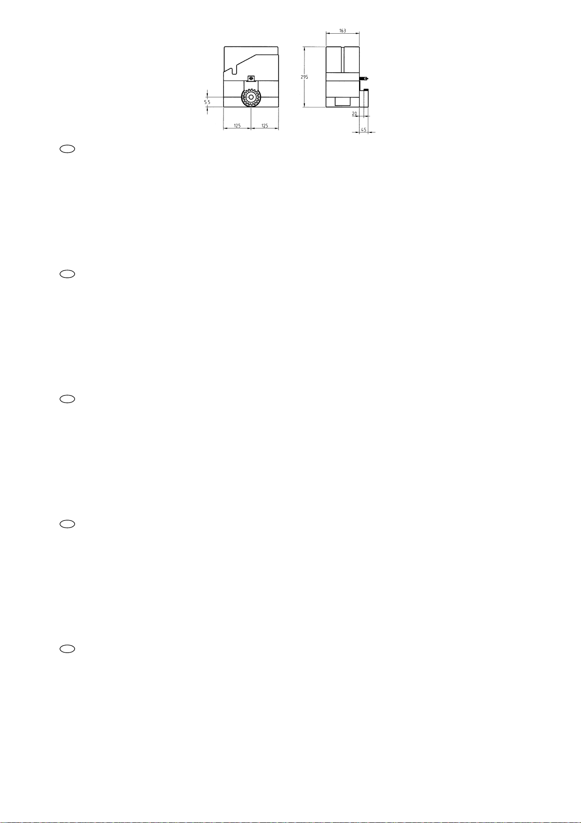
Fig. A
Page 4
4
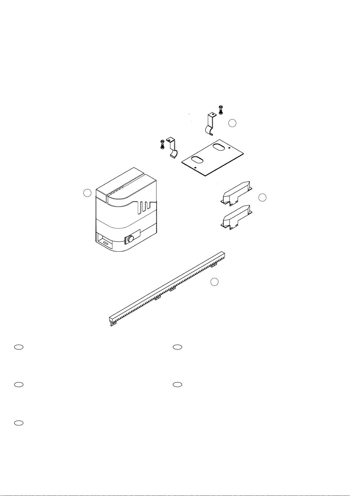
MATERIALI PER L’INSTALLAZIONE
INSTALLATIONSMATERIALIEN
INSTALLATION MATERIAL
MATERIAUX POUR L'INSTALLATION
MATERIALES PARA LA INSTALACIÓN
1 (Art. P-400CN) Cremagliera in nylon
2 (Art. P-400CP) Contropiastra di fondazione completa di zanche, viti e dadi
3 (Art. P-350----) Motoriduttore comprendente:
4 (Art. S-350F300140) nr. 2 camme (o pattini) di finecorsa
1 (Art. P-400CN) Nylon-Zahnstange
2 (Art. P-400CP) Fundamentgegenplatte mit Expansionsverankerungsbeinen,
Schrauben und Muttern
3 (Art. P-350----) Getriebemotor mit:
4 (Art. S-350F300140) nr. 2 Endgleitblöcke
1 (Art. 400CN) Nylon rack
2 (Art. 400CP) Foundation counter plate complete with fish-tail clamps,
screws and nuts
3 (Art. 350---) Geared motor including:
4 (Art. S-350F300140) nr. 2 end limit sliding blocks
1 (Art. P-400CN) Crémaillère en nylon
2 (Art. P-400CP) Contre-plaque de fondation avec agrafes, vis et écrous
3 (Art. P-350----) Motoréducteur comprenant:
4 (Art. S-350F300140) nr. 2 patins de fin de course
1 (Art. P-400CN) Cremallera de nylon
2 (Art. P-400CP) Contraplaca de cimentación completa con grapas, tornillos y tuercas
3 (Art. P-350---- ) Motorreductor que comprende
4 (Art. S-350F300140) nr. 2 patines de fin de carrera
1
4
2
3
I
GB
E
D
F
Fig. B
Page 5
5
Prima di procedere all'installazione controllare che:
● Le ruote del cancello siano montate in modo da rendere stabile il cancello, siano in buono stato ed efficienti;
● La rotaia di scorrimento sia libera, diritta e pulita su tutta la sua lunghezza e con battute di arresto alle estremità;
● La guida superiore sia in asse con la rotaia, sia lubrificata e consenta un gioco di circa 1mm. all'anta.
Bevor man mit der Installation beginnt, sich vergewissern, daß:
● die Räder des Gatters funktionstüchtig, in gutem Zustand und richtig montiert sind und dem Gatter Stabilität
verleihen;
● die Gleitschiene frei, gerade und sauber ist, und daß an deren Enden die Endanschläge vorhanden sind;
● die obere Führung mit der Schiene in einer Achse steht, gut geschmiert ist und dem Gatter einen Spielraum von ca.
1 mm ermöglicht.
Before you start installing check that:
● the gate wheels have been mounted to render the gate firm, that they are in good condition and efficient;
● the sliding rail is free, straight and clean along its entire length and that there are stop pads at the ends;
● the top guide is in axis with the rail, that it is lubricated and gives the gate about 1 mm play.
Avant de procéder à l’installation, contrôler que:
● Les roues du portail sont montées de manière à assurer sa stabilité, qu’elles sont en bon état et qu’elles fonctionnent
correctement;
● Le rail de glissement est libre, droit et propre sur toute sa longueur et avec des butées d’arrêt aux extrémités;
● Le guidage supérieur est dans l’axe du rail, qu’il est lubrifié et permet un jeu d’environ 1 mm au portail.
Antes de llevar a cabo la instalación controlar que:
● Las ruedas de la verja hayan sido montadas de manera que la verja tenga estabilidad, se encuentren en buen
estado y sean eficientes;
● El carril de deslizamiento esté libre, recto y limpio en toda su longitud y que tenga los topes de parada en las
extremidades;
● La guía superior esté en eje con el carril, esté lubrificada y permita un juego de aproximadamente 1 mm a la hoja.
CONSIDERAZIONI PRELIMINARI ALL'INSTALLAZIONE
EINLEITENDE EMPFEHLUNGEN FÜR DIE INSTALLATION
CONSIDERATIONS PRIOR TO INSTALLATION
CONSIDERATIONS PRELIMINAIRES A L'INSTALLATION
CONSIDERACIONES PRELIMINARES A LA INSTALACIÓN
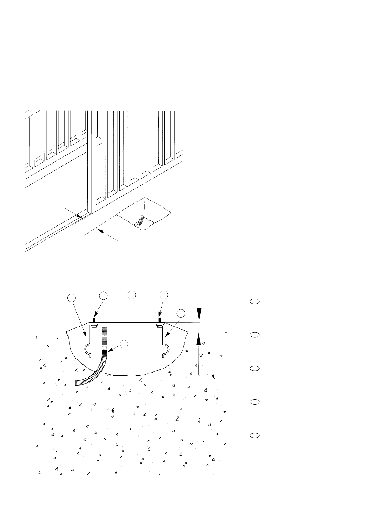
INDIVIDUAZIONE DEL SITO
AUSFINDIGMACHEN DER UNTERBRINGUNG
FINDING THE SITE
IDENTIFICATION DU SITE
LOCALIZACIÓN DE LA UBICACIÓN
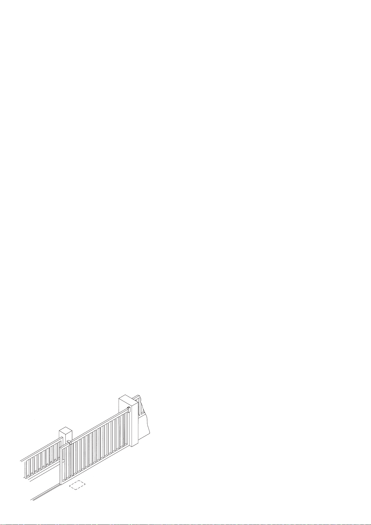
Scegliere una posizione analoga all'area tratteggiata di fig. C
Eine Position wählen, die der gestrichelt eingezeichneten Zone von Abb. C entspricht.
Choose a position that is identical to the dotted area in Fig. C.
Choisir une position analogue à la zone signalée en pointillé sur la fig. C.
Elegir una posición análoga al área punteada de la fig. C.
Fig. C
Page 6
6
PREPARAZIONE DELLA BASE
VORBEREITUNG DER BASIS
PREP ARING THE BASE
PREPARATION DE LA BASE
PREPARACIÓN DE LA BASE
Scavare le fondazioni per almeno cm. 15 di profondità e ben allargate.
Prevedere una guaina protettiva per i cavi.
Mindestens 15 cm Tiefe und genügend Breite Fundamente graben.
Für einen Kabelschutzmantel sorgen.
Dig comfortably wide foundations, at least 15 cm deep.
Protect the cables with a sheath.
Creuser les fondations sur au moins 15 cm de profondeur et bien larges.
Prévoir une gaine de protection pour les câbles.
Exavar los cimientos con una profundidad de unos 15 cm por lo menos y
bien ensaanchados.
Prever una funda protectora para los cables.
1 zanca
2 vite
3 contropiastra di fondazione
4 guaina di protezione cavi
1 Expansionsverankerungsbein
2 Schraube
3 Fundamentgegenplatte
4 Kabelschutzmantel
1 fish-tail clamp
2 screw
3 foundation counter plates
4 cable protection sheaths
1 agrafe
2 vis
3 contre-plaque de fondation
4 gaine de protection câbles
1 grapa
2 tornilo
3 contraplaca de cimentación
4 funda de protección de los cables
I
D
GB
F
E
65 mm
10÷20 mm
1
2
4
3 2
1
Fig. D
Fig. E
Page 7
7
Ricoprire con calcestruzzo annegando le zanche in cui vi sono state precedentemente infilate le viti.
Posare la contropiastra perfettamente piana ad 1 o 2 cm dal livello del terreno ed ad una distanza di 65 mm circa dal
cancello usando la cremagliera indicata (vedi fig. E).
NB: è possibile l'installazione del motoriduttore anche in assenza della contropiastra di fondazione semplicemente usando
due tasselli di fondazione su una base piana di calcestruzzo.
Die Expansionsverankerungsbeine, in die vorab die Schrauben eingefügt worden sind, einbetonieren.
Mit Hilfe der angegebenen Zahnstange die Gegenplatte perfekt flach 1 oder 2 cm vom Boden und ca. 65 mm vom Gatter
entfernt verlegen (siehe Abb. E).
MERKE: der Getriebemotor kann mit Hilfe zweier Fundamentdübel auf einer flachen Betonbasis auch ohne
Fundamentgegenplatte installiert werden.
Cover with concrete, burying the fish-tail clamps with the screws already in.
Lay the foundation counter plate so it is perfectly flat 1 to 2 cm from ground level and about 65 mm away from the gate using
the rack shown in Fig. E.
N.B. The geared motor can be installed without the foundation counter plate, in which case simply use two foundation plugs
on a flat concrete base.
Recouvrir de ciment en noyant les agrafes dans lesquelles ont été préalablement enfilées les vis.
Poser la contre-plaque parfaitement à plat à 1 ou 2 cm du niveau du sol et à une distance de 65 mm environ du portail en
utilisant la crémaillère indiquée (voir fig. E).
N.B. : on peut installer le motoréducteur même en l’absence de la contre-plaque de fondation simplement en utilisant deux
boulons de fondation sur une base plate en ciment.
Cubrir con hormigón sumergiendo la grapas en las que habrán sido anteriormente introducidos los tornilos.
Colocar la contraplaca perfectamente plana a 1 o 2 cm del nivel del terreno y a una distancia de 65 mm aproximadamente
de la verja usando la cremallera indicada (véase fig. E).
NOTA: es posible la instalación del motorreductor también sin la contraplaca de cimentación, sencilamente usando dos
tacos de cimentación sobre una base plana de hormigón.
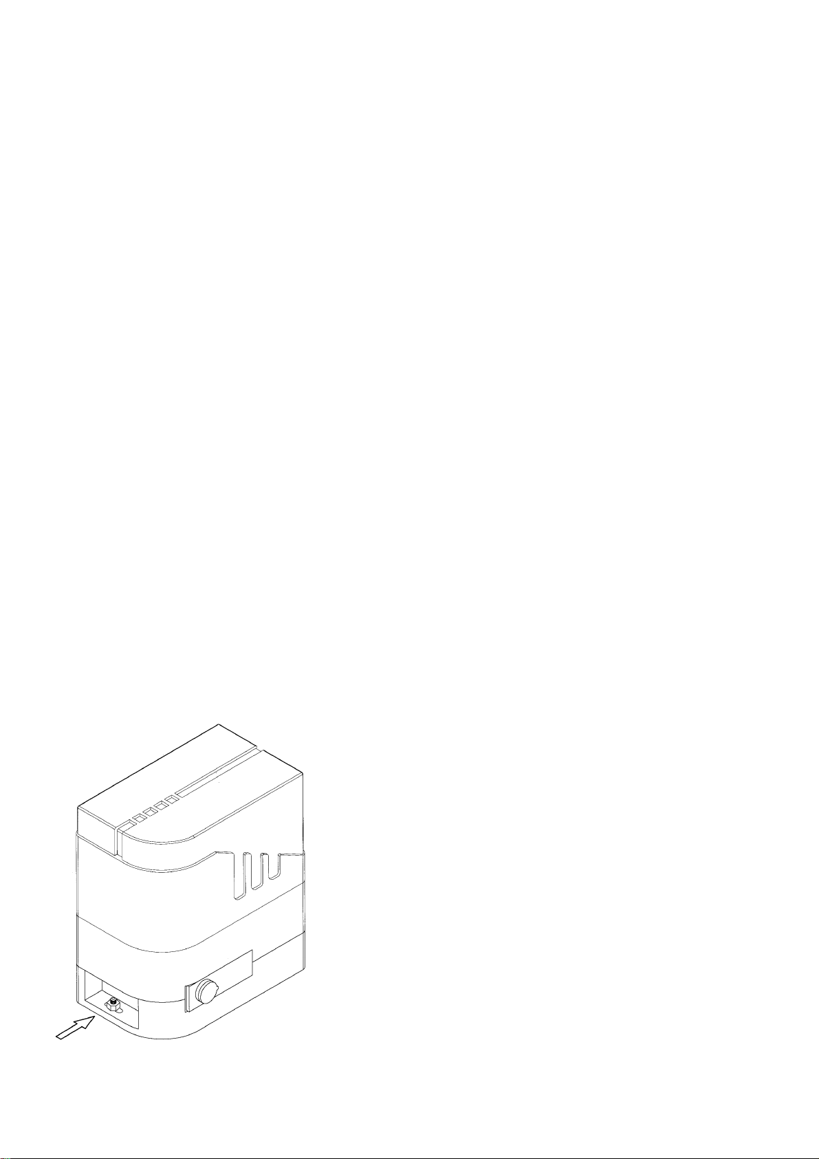
ANCORAGGIO MOTORIDUTTORE
VERANKERUNG DES GETRIEBEMOTORS
ANCHORING THE GEARED MOTOR
FIXATION DU MOTOREDUCTEUR
ANCLAJE DEL MOTORREDUCTOR
Avvitare i dadi (come evidenziato in fig. F) su entrambi i lati del motoriduttore.
Die Muttern (wie auf Abb. F dargestellt) beidseitig am Getriebemotor anschrauben.
Tighten the nuts (as shown in Fig. F) on both sides of the geared motor.
Visser les écrous (comme le montre la fig. F) sur les deux côtés du motoréducteur.
Enroscar las tuercas (como se indica en la fig. F) en ambos lados del motorreductor.
Fig. F
Page 8
8
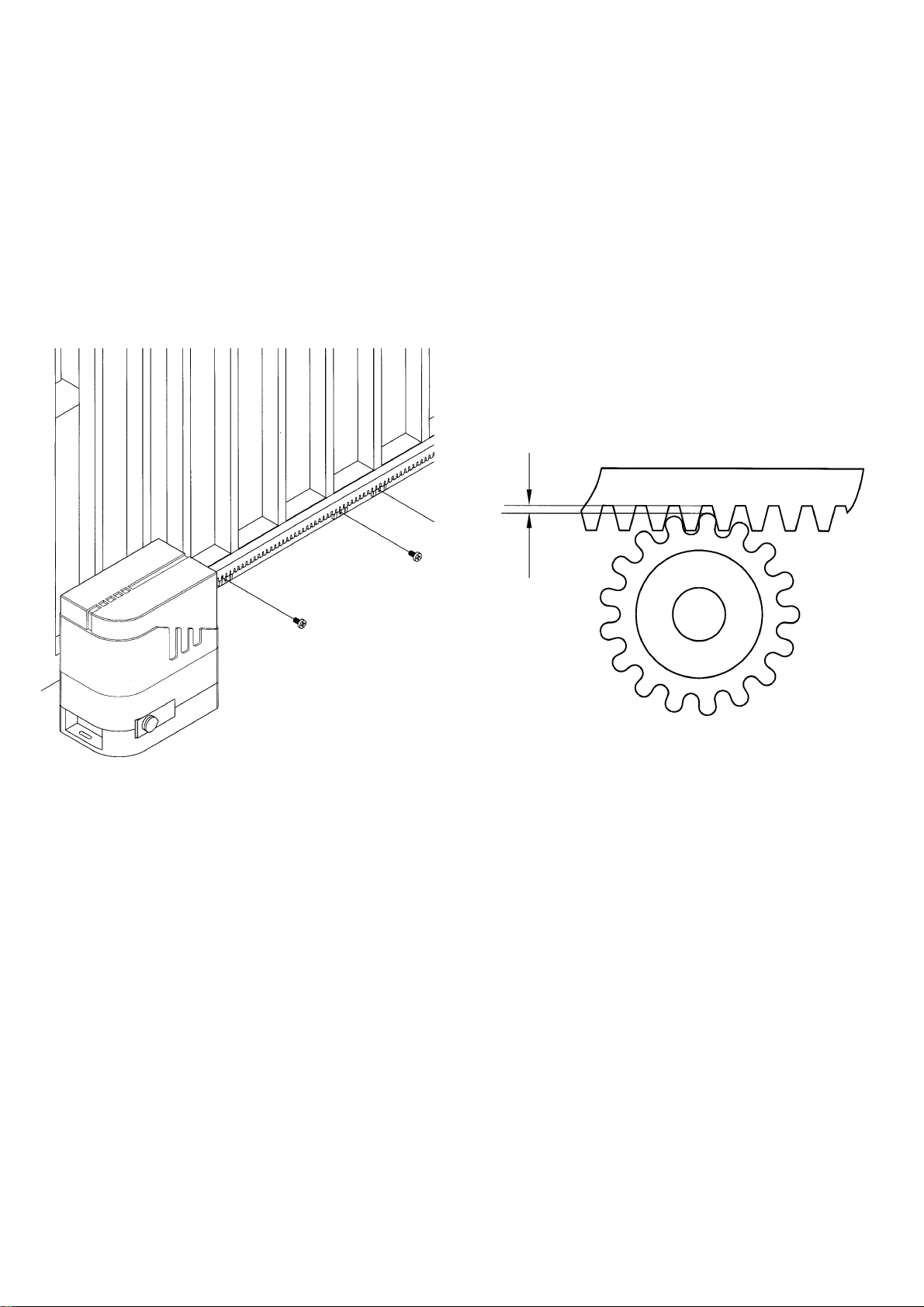
FISSAGGIO CREMAGLIERA
ZAHNSTANGENBEFESTIGUNG
FIXING THE RACK
FIXATION DE LA CREMAILLERE
FIJACIÓN DE LA CREMALLERA
Dopo aver forato l'anta, fissare la cremagliera al cancello con viti autofilettanti avente diametro 6.3 mm.
Rispettare le quote di fig. H.
Nachdem man das Gatter durchbohrt hat, die Zahnstange mit selbstschneidenden Schrauben, Durchmesser 6,3 mm, am Gatter
befestigen.
Sich an die in Abb. H angegebenen Maße halten.
Once the gate has been drilled fix the rack to it using 6.3 Ø self-threading screws.
Observe heights in Fig. H.
Après avoir percé le portail, fixer la crémaillère avec des vis autotaraudeuses de 6,3 mm de diamètre.
Respecter les mesures de la fig. H.
Después de haber perforado la hoja, fijar la cremallera a la verja con tornillos con autorroscado que tengan un diámetro de 6.3 mm.
Respetar las medidas de la fig. H.
1÷2 mm
Fig. G
Fig. H
Page 9
9
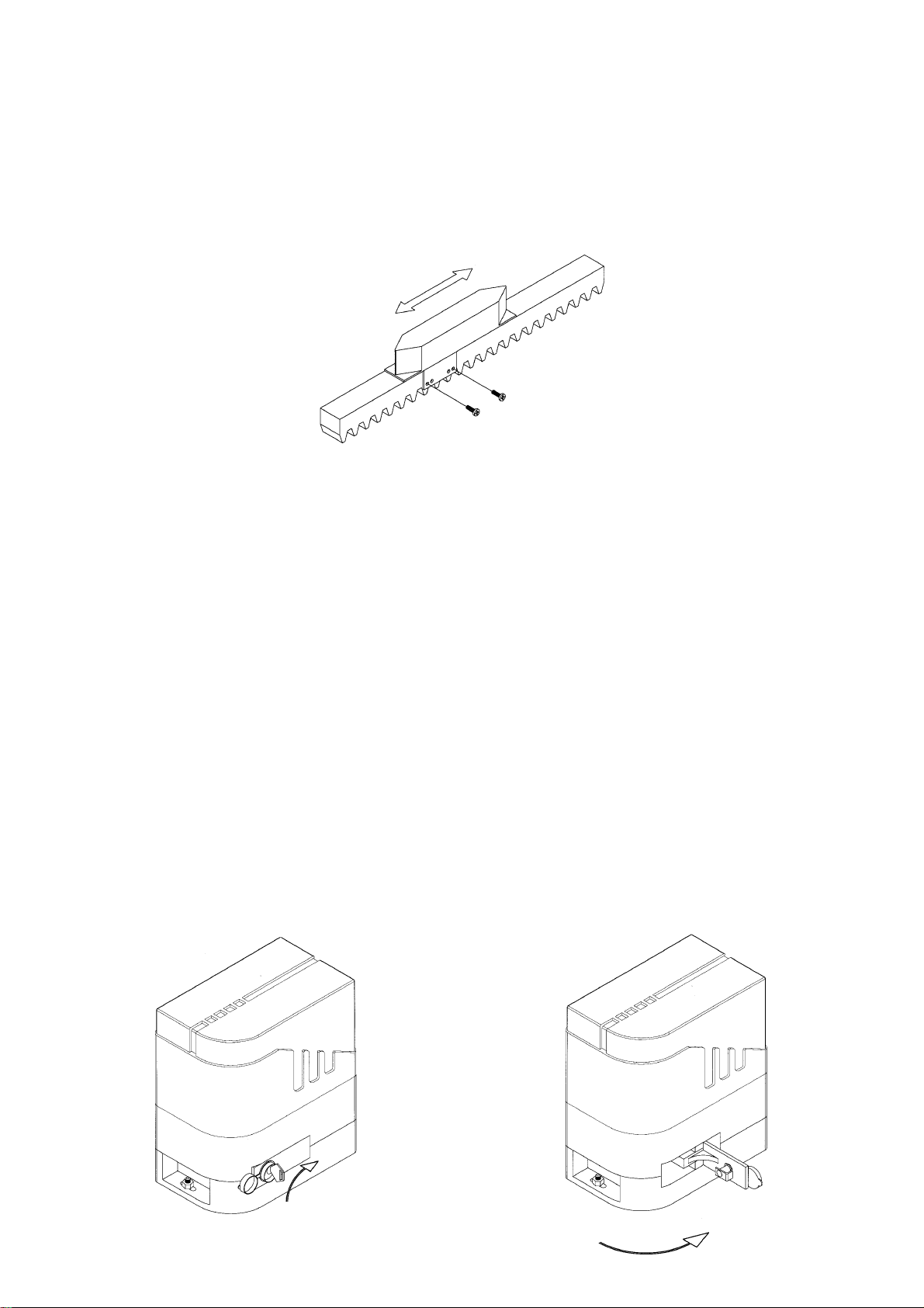
FISSAGGIO E REGOLAZIONI PATTINI DI FINECORSA
BEFESTIGUNG UND REGULIERUNG DER ENDGLEITBLÖCKE
FIXING AND ADJUSTING THE END LIMIT SLIDING BLOCKS
FIXATION ET REGLAGE DES PATINS DE FIN DE COURSE
FIJACIÓN Y REGULACIÓN DE LOS PATINES DE FIN DE CARRERA
USO SBLOCCO MANUALE
VERWENDUNG DER MANUELLEN ENTRIEGELUNG
USE OF MANUAL UNLOCKING
UTILISATION DU DEBLOCAGE MANUEL
UTILIZACIÓN DEL DESBLOQUEO MANUAL
Collocare i pattini come in fig. I e ciascuno vicino ad un estremo della cremagliera.
Movimentando l'anta manualmente, posizionare i pattini in modo che agiscano sulla leva del microinterruttore (leva a molla
posta sul retro dell'apparecchio) leggermente prima dell'intervento dei fermi meccanici di fine rotaia; quindi serrare le viti.
Die Gleitblöcke wie in Abb. I dargestellt jeweils am Ende der Zahnstange unterbringen.
Durch das manuelle Bewegen des Gatters die Gleitblöcke so positionieren, daß sie kurz vor dem Eingriff der mechanischen
Schienenendanschläge auf den Hebel des Mikroschalters wirken (Federhebel hinten am Getriebemotor): sodann die Schrauben
anziehen.
Position the blocks as shown in Fig. I, each one near one end of the rack. Moving the gate manually, position the blocks so they
make contact with the microswitch lever (a spring lever located behind the geared motor) just before the end-of-the-rail
mechanical stops intervene; now tighten the screws.
Placer les patins comme sur la fig. I, chacun à proximité d’une extrémité de la crémaillère. En bougeant le portail à la main,
positionner les patins de manière qu’ils agissent sur le levier du microinterrupteur (levier à ressort situé sur l’arrière de l’appareil)
légèrement avant l’intervention des butées mécaniques de fin de rail; serrer ensuite les vis.
Colocar los patines como se indica en la fig. I y cada uno de ellos cerca de una extremidad de la cremallera.
Moviendo la hoja manualmente, colocar los patines de manera que intervengan sobre la palanca del microinterruptor (palanca
de resorte colocada en la parte trasera del aparato) un poco antes de la intervención de los topes mecánicos del final del carril;
luego apretar los tornillos.
Fig. I
Fig. L Fig. M
Page 10

1010
REGISTRAZIONE FRIZIONE MECCANICA (mod. F8/F8Q )
EINSTELLEN DER MECHANISCHEN KUPPLUNG (mod. F8/F8Q)
ADJUSTING THE MECHANICAL FRICTION CLUTCH (mod. F8/F8Q)
REGLAGE EMBRAYAGE MECANIQUE (mod. F8/F8Q)
AJUSTE DEL EMBRAGUE MECÁNICO (mod. F8/F8Q)
Fig. N
Page 11

1111
COLLEGAMENTI ELETTRICI (F5 / F5Q / F8 / F8Q)
ELEKTROANSCHLÜSSE (F5 / F5Q / F8 / F8Q)
ELECTRICAL CONNECTIONS (F5 / F5Q / F8 /F8Q)
BRANCHEMENTS ELECTRIQUES (F5 / F5Q / F8 / F8Q)
CONEXIONES ELÉCTRICAS (F5 / F5Q / F8 / F8Q)
Per effettuare i collegamenti, togliere i carter ai motoriduttori e i coperchi alle schede di comando (vedi figg. O-P).
Usare cavi di sezione minima di 1.5 mm2per i circuiti di potenza, di 0.5 mm2per i circuiti di comando.
Um die Anschlüsse auszuführen, von den Getriebemotoren die Gehäuse und von den Schaltkarten die Deckel abnehmen (siehe
Abb.en O-P).
Für die Leistungskreise Kabel mit einem Mindestquerschnitt von 1.5 mm2einsetzen, für die Schaltkreise hingegen mit einem
Querschnitt von 0.5 mm2.
To connect remove the casings from the geared motors and covers from the control cards (see Figs. O-P).
Use cables with a minimum cross section of 1.5 mm2for the power circuits and 0.5 mm2for the control circuits.
Pour effectuer les branchements, enlever les carters des motoréducteurs et les couvercles des cartes de commande (voir fig. O-P).
Utiliser des câbles d’une section minimum d’1,5 mm2pour les circuits de puissance et de 0,5 mm2pour les circuits de commande.
Para realizar las conexiones quitar los cárteres a los motorreductores y las tapas a las tarjetas de mando (véase fig. O-P).
Usar cables con sección mínima de 1.5 mm2para los circuitos de potencia, de 0.5 mm2para los circuitos de mando.
Fig. O Fig. P
Page 12

12
K990
Page 13

13
DESCRIZIONE FUZIONAMENTO DELLA SCHEDA DI COMANDO K990 PER MODELLI F5Q / F8Q
Quadro comando per l'azionamento a distanza di un motore elettrico monofase, atto all'automazione di un cancello
scorrevole, a funzionamento automatico o semiautomatico.
Funzionamento automatico: ad ogni comando di apertura si dà inizio ad un ciclo di lavoro che si completa con la richiusura
del cancello.
Funzionamento semiautomatico: l'azionamento del cancello richiede distinti comandi per l'apertura e la richiusura.
Sia nel funzionamento automatico che semiautomatico si potrà ottenere l'inversione di marcia sia nella fase di apertura che
nella fase di chiusura indistintamente.
L'inversione di marcia può essere limitata alla sola fase di chiusura chiudendo l'apposito ponticello, questo per evitare che
più comandi successivi, radiotrasmessi in fase di apertura da distanze superiori a quelle visibili, richiudano il cancello
erroneamente.
Il quadro comando K990 è indicato per l'azionamento di motoriduttori provvisti di limitatore di coppia; offre comunque la
possibilità di inserimento ad una schedina con frizione elettronica.
Questo quadro è dotato inoltre di quattro led-spia di rapida consultazione in grado di rilevare lo stato logico degli ingressi,
evitando così inutili perdite di tempo dovute alla verifica dei vari dispositivi esterni in ingresso.
COLLEGAMENTI E CARATTERISTICHE TECNICHE
1-2 Alimentazione 220 Vac-50 Hz per motore monofase 0,75 Hp.
3-4 Uscita 20 Vac per lampeggiante.
5 Comune motore.
6 Fase motore apertura.
7 Fase motore chiusura.
N.B. - IL COLLEGAMENTO DEL CONDENSATORE VA EFFETTUATO TRA LE DUE FASI DEL MOTORE (6-7).
8-9 Uscita 24 Vac per alimentazione dispositivi di sicurezza e/o altro (fotocellule, coste sensibili, relé luci).
10-11 Uscita 24 Vac per spia segnalazione cancello aperto. La spia rimane accesa fino alla completa richiusura del
cancello, oppure fino allo schiacciare del pulsante di STOP.
12-14 Pulsante di STOP (contatto N.C.). Allo schiacciare del pulsante di STOP viene momentaneamente interrotta
l'alimentazione alla logica del quadro, conseguentemente il motore si arresta dovunque si trovi, la spia cancello
aperto si spegne, e nel caso in cui sia stata programmata la richiusura automatica, questa si disinserisce. Per il
ripristino del normale ciclo di funzionamento occorrerà schiacciare il pulsante di marcia o il pulsante della
radiotrasmittente, tenendo presente che la prima manovra sarà sempre quella di apertura. Nel caso che questo
pulsante non venisse utilizzato sarà indispensabile cortocircuitarlo (N.C.).
13-14 Pulsante di marcia (contatto N.A.). Ad ogni impulso si darà inizio ad una manovra nella direzione opposta alla
precedente; quindi una apertura se il cancello è chiuso, ed una chiusura se il cancello è aperto. Durante il
movimento invece si ha la possibilità di invertire la marcia, questa inversione può essere limitata alla sola fase di
chiusura inserendo il ponticello N.R.
L'impulso della radiotrasmittente si comporterà in egual modo al pulsante di marcia.
15-18 Ingresso finecorsa di apertura (contatto N.C.). Nel caso in cui questo ingresso non venisse utilizzato sarà
indispensabile cortocircuitarlo N.C.
16-18 Ingresso finecorsa di apertura (contatto N.C.). Nel caso in cui questo ingresso non venisse utilizzato sarà
indispensabile cortocircuitarlo N.C.
17-18 Ingresso contatto fotocellula o altri dispositivi di protezione quali coste pneumatiche o altro (contatto N.C.). Nel caso
in cui questo ingresso non venisse utilizzato sarà indispensabile cortocircuitarlo N.C.. Nel momento in cui si ha
l'apertura del contatto, conseguente all'intervento dei dispositivi di protezione in fase di chiusura del cancello, si avrà
l'inversione di marcia. Con il ponticello FTA inserito la sicurezza interviene anche in fase di apertura bloccando il
cancello, solo ad ostacolo rimosso il cancello proseguirà la sua corsa di apertura.
19 Collegamento massa antenna RX Radioricevente.
20 Collegamento centrale o segnale antenna RX Radioricevente.
21-22 Uscita secondo canale della radioricevente (se bicanale).
✤Per il motoriduttore F5Q il quadro elettrico è provvisto di una frizione di tipo elettronico regolabile mediante il
TRIMER TF.
(La versione F8Q ne risulta ovviamente sprovvista).
PONTICELLO N.R.
A ponticello chiuso si avrà la possibilità di invertire la marcia soltanto durante la fase di chiusura. A ponticello aperto l'inversione di marcia sarà possibile in entrambi i sensi.
I
Page 14

14
PONTICELLO F.T.A.
A ponticello chiuso i dispositivi di sicurezza, facenti capo ai morsetti 18-19, interverranno anche durante l'apertura bloccando
il cancello e ripristinando la marcia solo ad ostacolo rimosso. A ponticello aperto i dispositivi di sicurezza intervengono solo
in chiusura invertendo il senso di marcia.
PONTICELLO T.C.A.
A ponticello chiuso si ha il funzionamento automatico del cancello con il seguente ciclo di lavoro:
marcia di apertura-pausa-marcia di chiusura
A ponticello aperto si ha il funzionamento semiautomatico del cancello e pertanto il suo funzionamento richiede distinti
comandi per l'apertura e la chiusura.
TL: TRIMMER DI REGOLAZIONE DEL TEMPO DI LAVORO (0-120 sec).
Il tempo di lavoro è il tempo utile che il cancello impiega per compiere un'intera manovra. Si consiglia di regolare il trimmer
TL per un tempo di lavoro, visualizzato dal led acceso POWER M. di qualche secondo superiore.
TCA: TRIMMER DI REGOLAZIONE DEL TEMPO DI PAUSA (0-120 sec.).
Il tempo di pausa è il tempo durante il quale il cancello resta fermo in apertura per poi richiudersi allo scadere dello stesso
tempo. Il conteggio inizia ogni qualvolta il cancello arrivi in fine-corsa di apertura o termini il tempo di lavoro sempre in
apertura. Esso si interrompe anche al sopraggiungere di un comanda di richiusura e si disinserisce temporaneamente
premendo il comando di STOP.
BETRIEBSBESCHREIBUNG DER SCHALTKARTE K990 FÜR MODELLE F5Q / F8Q
Steuertafel für den Fernantrieb eines einphasigen Elektromotors für die Automatisierung eines Schiebetores, mit
automatischem oder halbautomatischem Betrieb.
Automatischer Betrieb: bei jedem Öffnungsbefehl wird der Start zu einem Arbeitszyklus gegeben, der mit dem Schließen
des Tors abgeschlossen wird.
Halbautomatischer Betrieb: der Antrieb des Tors erfordert unterschiedliche Befehle für das Öffnen und das Schließen.
Sowohl im automatischen als auch im halbautomatischen Betrieb kann der Gang unterschiedslos in der Öffnungsphase
ebenso wie in der Schließphase umgekehrt werden.
Die Umkehr des Gangs kann auf lediglich die Schließphase beschränkt werden, indem die entsprechende
Überbrückungsklemme geschlossen wird; dies, um zu vermeiden, daß mehrere aufeinanderfolgende Befehle, während der
Öffnungsphase durch Funk aus Entfernungen übertragen, die über den sichtbaren liegen, das Tor irrtümlicherweise wieder
schließen.
Die Steuertafel K990 ist für den Antrieb von Getriebemotoren geeignet, die mit Drehmomentbegrenzer ausgestattet sind;
sie bietet aber auf jeden Fall die Möglichkeit zum Einsatz einer Karte mit elektronischem Drehmomentbegrenzer.
Diese Schalttafel ist darüberhinaus mit vier Kontrolleuchtdioden zur schnellen Überprüfung ausgestattet und in der Lage,
den logischen Zustand der Eingänge festzustellen, so daß überflüssige Zeitverluste aufgrund der Überprüfung von
verschiedenen externen Vorrichtungen im Eingang vermieden werden.
ANSCHLÜSSE UND TECHNISCHE EIGENSCHAFTEN
1-2 Speisung 220 Vac - 50 Hz für einphasigen Motor 0,75 Hp.
3-4 Ausgang 20 Vac für Blinklicht.
5 Gemeinsame Motor.
6 Phase Motor Öffnung.
7 Phase Motor Schließung
BITTE BEACHTEN: DER ANSCHLUß DES KONDENSATORS MUß ZWISCHEN DEN BEIDEN PHASEN DES MOTORS
(6-7) ERFOLGEN.
8-9 Ausgang 24 Vac für die Speisung der Sicherheitsvorrichtungen und/oder anderem (Photozellen,
Sicherheitsfühlleisten, Relais der Leuchten).
10-11 Ausgang 24 Vac für die Kontrolleuchte zur Signalierung des geöffneten Tors. Die Kontrolleuchte bleibt bis zur
vollständigen Schließung des Tors oder bis zum Drücken der STOP-Taste eingeschaltet.
12-14 STOP-Taste (Kontakt normalerweise geschlossen). Bei Drücken der STOP-Taste wird die Speisung der Logik
der Schalttafel zeitweilig unterbrochen; infolgedessen stoppt der Motor, gleich wo er sich befindet, die
Kontrolleuchte für das geöffnete Tor schaltet sich aus und, falls eine automatische Wiederschließung program
miert worden sein sollte, wird diese deaktiviert. Für die Rückstellung des normalen Betriebszyklus müssen die
Betriebstaste oder die Taste des Funksenders gedrückt werden; dabei muß berücksichtigt werden, daß zuerst
immer ein Öffnungsmanöver erfolgen wird. Sollte diese Taste nicht verwendet werden, so muß er unbedingt
kurzgeschlossen werden (normalerweise geschlossen).
13-14 Betriebstaste (Kontakt normalerweise geöffnet). Bei jedem Impuls wird ein Manöver in die Richtung gestartet, die
der vorhergegangenen entgegengesetzt liegt; d.h., eine Öffnung, wenn das Tor geschlossen ist, und eine
Schließung, wenn das Tor offen ist. Während der Bewegung hingegen besteht die Möglichkeit zur Umkehr des
D
Page 15

15
Gangs; diese Umkehr kann auf lediglich die Schließphase begrenzt werden, indem die Überbrückungsklemme N.R.
eingesetzt wird.
Der Impuls des Funksenders verhält sich auf die gleiche Weise wie die Betriebstaste.
15-16 Eingang Endschalter für die Öffnung (Kontakt normalerweise geschlossen). Sollte dieser Eingang nicht verwendet
werden, so muß er unbedingt kurzgeschlossen werden (normalerweise geschlossen).
16-18 Eingang Endschalter für die Öffnung (Kontakt normalerweise geschlossen).
Sollte dieser Eingang nicht verwendet werden, so muß er unbedingt kurzgeschlossen werden (normalerweise
geschlossen).
17-18 Eingang Kontakt Photozellen oder andere Sicherheitsvorrichtungen wie Sicherheitsfühlleisten oder anderes (Kontakt
normalerweise geschlossen). Sollte dieser Eingang nicht verwendet werden, so muß er unbedingt kurzgeschlossen
werden (normalerweise geschlossen). In dem Moment, in dem die Öffnung des Kontaktes erfolgt, als Folge eines
Eingreifens der Schutzvorrichtungen während der Schließphase des Tores, erfolgt die Umkehr des Gangs. Mit
eingesetzter Überbrückungsklemme FTA greift die Sicherheit auch in der Öffnungsphase ein und blockiert das Tor;
nur wenn das Hindernis beseitigt worden ist, kann das Tor den Öffnungslauf fortführen.
19 Anschluß der Masse Antenne RX Funkempfänger.
20 Zentralanschluß oder Anschluß des Signals der Antenne RX Funkempfänger.
21-22 Ausgang des zweiten Kanals des Funkempfängers (wenn mit zwei Kanälen).
✤ Für den Getriebemotor F5Q ist die Schalttafel mit einem elektronischen
Drehmomentbegrenzer ausgestattet, der über den TRIMER TF reguliert werden kann.
(Die Ausführung F8Q ist selbstverständlich nicht ausgestattet).
ÜBERBRÜCKUNGSKLEMME N.R.
Mit geschlossener Überbrückungsklemme besteht die Möglichkeit zur Umkehr des Gangs nur während der Schließphase
Mit geöffneter Überbrückungsklemme ist die Umkehr des Gangs in beide Richtungen möglich.
ÜBERBRÜCKUNGSKLEMME F.T.A.
Mit geschlossener Überbrückungsklemme greifen die Sicherheitsvorrichtungen, die in den Klemmen 18-19 enden, auch
während der Öffnungsphase ein und blockieren das Tor; die Rückstellung des Gangs kann nur erfolgen, wenn das Hindernis
beseitigt worden ist.
ÜBERBRÜCKUNGSKLEMME T.C.A.
Bei geschlossener Überbrückungsklemme erfolgt der automatische Betrieb des Tors mit dem folgenden Arbeitszyklus:
Öffnungsgang-Pause-Schließgang
Bei geöffneter Überbrückungsklemme erfolgt der halbautomatische Betrieb des Tors und sein Funktionieren erfordert daher
unterschiedliche Befehle für das Öffnen und die Schließung.
TL.: TRIMMER ZUR REGULIERUNG DER ARBEITSZEIT (0-120 Sekunden).
Die Arbeitszeit ist die äußerste Zeit, die das Tor benötigt, um ein vollständiges Manöver auszuführen. Es wird eine
Regulierung des Trimmers TL für eine Arbeitszeit empfohlen, die um einige Sekunden über der von der eingeschalteten
Leuchtdiode POWER M. angezeigten liegt.
TCA: TRIMMER ZUR REGULIERUNG DER PAUSENZEIT (0-120 Sekunden).
Die Pausenzeit ist die Zeit während der das Tor in der Öffnung stehen bleibt, um sich dann bei Ablauf dieser Zeit wieder zu
schließen. Die Zählung beginnt jedesmal dann, wenn das Tor am Endschalter der Öffnung oder bei Ablauf der Arbeitszeit,
immer in der Öffnung, ankommt. Sie wird auch dann unterbrochen, wenn plötzlich ein Befehl zur Wiederschließung erfolgt
und sie schaltet sich zeitweilig aus, wenn der STOP-Befehl gedrückt wird.
DESCRIPTION OF HOW THE CONTROL CARD K990 WORKS FOR MODELS F5Q / F8Q
This control panel is used to remotely start a single phase electric motor used for the automation of a sliding gate, working
automatically or semi-automatically.
When working automatically: each time an opening command is given a work cycle is started that ends when the gate closes
again.
When working semi-automatically: the gate requires distinct commands in order for it to open and close.
The gate can be reversed in both automatic and semi-automatic functioning modes, whether it is opening or closing without
any distinction.
Reversal can be limited to the closing phase by plugging in the corresponding jumper; this will make it impossible for
subsequent commands - transmitted via radio when opening from distances greater than those visible - to accidentally close
the gate.
The K990 control panel is suitable for starting geared motors equipped with a torque limiting device; there is also the
possibility of plugging in a card for electronic friction.
There are four indicator LEDs on the panel that quickly inform you of the inputs’ logical state which saves a lot of time
checking the various external devices in input.
GB
Page 16

16
CONNECTIONS AND TECHNICAL FEATURES
1-2 220 Vac-50Hz power and frequency for single phase 0.75 HP motors.
3-4 20 Vac output for the flashing light.
5 Motor’s common wire.
6 Motor opening phase.
7 Motor closing phase.
N.B. The capacitor should be connected between the two motor phases (6-7).?
8-9 24 Vac output to power the safety devices and/or other devices (photoelectric cells, sensitive edge, light relays).
10-11 24 Vac output for gate open indicator light. This light stays on until the gate has closed completely or until the STOP
button is pressed.
12-14 STOP push button (N.C. contact). Power to the panel logic is temporarily interrupted when the STOP button is
pressed; as a result the motor stops in whatever position it finds itself, the gate open indicator light turns off and
if automatic reclosing was programmed it will be disabled. To reset the normal operating cycle press either the start
button or the transmitter button, remembering that the first manoeuvre will always be an opening one. This button
must be shortcircuited (N.C.) if it is not going to be used.
13-14 Start push button (N.O. contact). Each time this button is pressed it will start a manoeuvre opposite to the previous
one: it will open the gate if it was closed or close it if it was open. When the gate is moving you can reverse its
direction; reversal can be limited to just the closing phase by plugging the N.R. jumper in.
The transmitter pulse will act in exactly the same as the start button.
15-18 Opening limit switch input (N.C. contact). This input must be shortcircuited (N.C.) if it is not going to be used.
16-18 Opening limit switch input (N.C. contact). This input must be shortcircuited (N.C.) if it is not going to be used.
17-18 Contact input for a photoelectric cell or other protection device such as pneumatic edges etc. (N.C. contact). This
input must be shortcircuited (N.C.) if it is not going to be used. The moment the contact opens, subsequent to the
protection devices triggering during the gate closing phase, gate direction will reverse. With the FTA jumper plugged
in, the safety device will also trigger during the opening phase, stopping the gate; the gate will continue is opening
travel only when the obstacle has been removed.
19 RX receiver aerial earthing connection.
20 RX receiver aerial signal or central connection.
21-22 The receiver’s second channel output (if it has two channels).
✤ The electric panel has an electronic type friction for the F5Q geared motor, adjustable with the TF trimmer.
(The F8Q version is obviously without.)
JUMPER N.R.
With this jumper you have the possibility of reversing direction only during the closing phase. Without the jumper you can
reverse direction both ways.
JUMPER F.T.A.
With this jumper the safety devices - connected to terminals 18-19 - will trigger also during the opening phase, stopping the
gate and restarting it only after the obstacle has been removed. Without the jumper the safety devices will only trigger in the
closing phase, reversing the direction.
JUMPER T.C.A.
With this jumper the gate will work automatically with the following working sequence:
open - pause - close
Without the jumper the gate will work semi-automatically which means it requires distinct commands to open and close it.
TL: WORKING TIME ADJUSTMENT TRIMMER (0-120 seconds)
By working time we mean the time the gate takes to complete a full manoeurvre. We suggest you adjust the TL trimmer
adding a few extra seconds to the working time which is displayed by the illumination of the POWER M LED.
TCA: PAUSE TIME ADJUSTMENT TRIMMER (0-120 seconds)
By pause time we mean the time the gates stands still when open and then reclose when this time is up. Counting starts
each time the gate reaches the end of its opening travel or when working time finishes (always in the opening phase). It can
be interrupted if a closing command is given and will be temporarily disabled when the STOP command button is pressed.
DESCRIPTION DU FONCTIONNEMENT DE LA CARTE DE COMMANDE K990 POUR MODELES F5Q/F8Q
Coffret de commande pour l'actionnement à distance d'un moteur électrique monophasé, pour l'automatisation d'un portail
coulissant à fonctionnement automatique ou semi-automatique.
F
Page 17

17
Fonctionnement semi-automatique: à chaque commande d'ouverture, on commence un cycle de travail qui se complète
avec la refermeture du portail.
Fonctionnement semi-automatique: l'actionnement du portail demande des commandes distinctes pour l'ouverture et la
refermeture du portail.
Pour le fonctionnement automatique tout comme pour le semi-automatique, on peut obtenir l'inversion de marche aussi bien
durant la phase d'ouverture que durant celle de fermeture, ceci indistinctement.
L'inversion de marche peut se limiter uniquement à la phase de fermeture en fermant la connexion volante appropriée, ceci
afin d'éviter que plusieurs commandes successives, émises par radio en phase d'ouverture à des distances supérieures à
celles visibles, ne referment le portail erronément.
Le coffret de commande K990 est indiqué pour l'actionnement de moto-réducteurs équipés de limiteur de couple; il offre la
possibilité d'introduction d'une carte avec embrayage électronique.
Ce coffret est également équipé de quatre voyants-témoins de consultation rapide en mesure de relever l'état logique des
entrées, en évitant ainsi d'inutiles pertes de temps dues au contrôle des différents dispositifs externes d'entrée.
CONNEXIONS ET CARACTERISTIQUES TECHNIQUES
1-2 Alimentation 220 Vac-50Hz pour moteur monophasé 0,75 Hp.
3-4 Sortie 20 Vac pour clignotant.
5 Commune moteur.
6 Phase moteur ouverture.
7 Phase moteur fermeture.
N.B.- LA CONNEXION DU CONDENSATEUR DOIT ETRE EFFECTUEE ENTRE LES DEUX PHASES DU MOTEUR (6-7).
8-9 Sortie 24 Vac pour alimentation dispositifs de sécurité et/ou autre (cellules photoélectriques, barres palpeuses
sensibles, relais lumières).
10-11 Sortie 24 Vac pour témoin de signalisation portail ouvert. Le témoin reste allumé jusqu'à la refermeture complète du
portail ou bien jusqu'à ce que l'on appuie sur le bouton STOP.
12-14 Bouton STOP (contact N.F.). Lorsque l'on appuie sur le bouton STOP l'alimentation à la logique du coffret est
momentanément interrompue; conséquemment le moteur s'arrête à l'endroit où il se trouve, le témoin portail ouvert
s'éteint et au cas où l'on ait programmé la refermeture automatique, celle-ci se déconnecte. Pour le rétablissement
du cycle de fonctionnement normal, il faut presser le bouton de marche ou celui de l'émetteur, en tenant compte que
la première manœuvre est toujours celle d'ouverture. Au cas où ce bouton ne soit pas utilisé, il est indispensable de
le court-circuiter. (N.F.).
13-14 Bouton de marche (contact N.O). A chaque impulsion, une manœuvre dans la direction opposée à la précédente
commence; par conséquent une ouverture si le portail est fermé et une fermeture si le portail est ouvert. Durant le
mouvement on a au contraire la possibilité d'inverser la marche; cette inversion peut se limiter à la seule phase de
fermeture en branchant la connexion volante N. R.
L'impulsion de l'émetteur se comporte de la même façon que le bouton de marche.
15-18 Entrée fin de course d'ouverture (contact N. F.): Au cas où cette entrée ne soit pas utilisée, il est indispensable de la
court-circuiter N.F.
16-18 Entrée fin de course (contact N. F.). Au cas où cette entrée ne soit pas utilisée, il est indispensable de la
court-circuiter N.F.
17-18 Entrée contact cellule photoélectrique ou autres dispositifs de protection comme barres palpeuses pneumatiques
ou autre (contact N.F.). Au cas où cette entrée ne soit pas utilisée, il est indispensable de la court-circuiter N.F. Du
moment que l'on a l'ouverture du contact, conséquente à l'intervention des dispositifs de protection en phase de
fermeture du portail, on a l'inversion de marche. Avec la connexion F.T.A. branchée, la sécurité intervient même en
phase d'ouverture en bloquant le portail; celui-ci ne poursuivra sa course d'ouverture que lorsque l'obstacle aura été
enlevé.
19 Liaison masse antenne RX Récepteur.
20 Liaison centrale ou signal antenne RX Récepteur
21-22 Sortie deuxième canal du récepteur (si bicanal).
✤ Pour le moto-réducteur F5Q le coffret électrique est équipé d'un embrayage du type électronique réglable au
moyen du TRIMMER TF.
(La version F8Q en est évidemment dépourvue).
CONNEXION VOLANTE N.R.
Lorsque la connexion volante est fermée, on a la possibilité d'inverser la marche uniquement durant la phase de fermeture.
Lorsque la connexion volante est ouverte, l'inversion de marche est possible dans les deux sens.
Page 18

18
CONNEXION F.T.A.
Lorsque la connexion volante est fermée, les dispositifs de sécurité, qui aboutissent aux bornes 18-19,
interviennent également durant l'ouverture en bloquant le portail et en rétablissant la marche seulement lorsque l'obstacle
est enlevé. Lorsque la connexion volante est ouverte, les dispositifs de sécurité interviennent uniquement durant la
fermeture en inversant le sens de marche.
CONNEXION T.C.A.
Lorsque la connexion volante est fermée, on a le fonctionnement automatique du portail avec le cycle de travail suivant:
marche d'ouverture-pause-marche de fermeture
Lorsque la connexion volante est ouverte, on a le fonctionnement semi-automatique du portail et par conséquent son
fonctionnement demande des commandes bien distinctes pour l'ouverture et la fermeture.
TL: TRIMMER DE REGLAGE DU TEMPS DE TRAVAIL (0-120 sec.).
Le temps de travail est le temps utile que le portail met à effectuer une manœuvre complète. On conseille de régler le
trimmer TL pour un temps de travail, visualisé par le voyant allumé POWER M., supérieur de quelques secondes.
TCA: TRIMMER DE REGLAGE DU TEMPS DE PAUSE (0-120 sec.).
Le temps de pause est le temps durant lequel le portail reste en arrêt durant l'ouverture pour se refermer lorsque le temps
en question expire. Le comptage commence à chaque fois que le portail arrive en fin de course d'ouverture ou que le temps
de travail termine, toujours en ouverture. Il s'interrompt même lorsqu'une commande de refermeture intervient et il se
débranche temporairement en pressant la commande STOP.
DESCRIPCIÓN DEL FUNCIONAMIENTO DE LA TARJETA DE MANDO K990 PARA LOS MODELOS F5Q/F8Q
Cuadro de mando para el accionamiento a distancia de un motor eléctrico monofásico, apto para la automatización de una
verja corrediza, con funcionamiento automático o semiautomático.
Funcionamiento automático: con cada mando de apertura se da comienzo a un ciclo de trabajo que finaliza al cerrarse la
verja.
Funcionamiento semiautomático: el accionamiento de la verja requiere diferentes mandos para la apertura y el cierre.
Tanto con el funcionamiento automático como con el semiautomático, se podrá obtener la inversión de marcha en la fase
de apertura como en la de cierre, indiferentemente.
La inversión de marcha puede ser limitada a una sola fase de cierre, cerrando el conectador puente relativo, para evitar que
varios mandos sucesivos radiotransmitidos en fase de apertura a distancias superiores de las visibles, vuelvan a cerrar la
verja por error.
El cuadro de mando K990 está indicado para el accionamiento de motorreductores provistos de limitador de par; ofrece de
cualquier modo la posibilidad de accionamiento a una pequeña tarjeta con embrague electrónico.
Este cuadro, además, está dotado de cuatro led-indicador de rápida consulta capaz de captar el estado lógico de los
accesos, evitando de esta manera inútiles pérdidas de tiempo debidas a la comprobación de los distintos dispositivos
exteriores de acceso.
CONEXIÓN Y CARACTERÍSTICAS TÉCNICAS
1-2 Alimentación 220 Vac-50 Hz para motor monofásico 0,75 Hp..
3-4 Salida 20 Vac para intermitente.
5 Común motor.
6 Fase motor apertura.
7 Fase motor cierre.
NOTA: - LA CONEXIÓN DEL CONDENSADOR TIENE QUE EFECTUARSE ENTRE LAS DOS FASES DEL MOTOR (6-7).
8-9 Salida 24 Vac para alimentación dispositivos de seguridad y/u otros (fotocélulas, costas sensibles, relé luces).
10-11 Salida 24 Vac para indicador de señalización de verja abierta. El indicador permanece encendido hasta el completo
cierre de la verja, o bien hasta que se aprieta el pulsador de STOP.
12-14 Pulsador de STOP (contacto N.C.). Cuando se aprieta el pulsador de STOP es momentáneamente interrumpida la
alimentación en la lógica del cuadro, por consiguiente el motor se para en cualquier lugar se encuentre, el indicador
de verja abierta se apaga y, en el caso de que haya sido programado el cierre automático, éste se desactiva. Para
el restablecimiento del normal ciclo de funcionamiento será necesario apretar el pulsador de marcha o el pulsador
de la radio transmisora, teniendo en cuenta que la primera maniobra será siempre la de apertura. En caso de que
este pulsador no fuera utilizado, será indispensable cortocircuitarlo (N.C.).
13-14 Pulsador de marcha (contacto N.A.). A cada impulso se dará comienzo a una maniobra en la dirección opuesta a la
anterior; por lo tanto, una apertura si la verja está cerrada y un cierre si la verja está abierta. Durante el movimiento,
por el contrario, se tiene la posibilidad de invertir la marcha, esta inversión puede ser limitada sólo a la fase de
cierre activando el conectador puente N.R. El impulso de la radio transmisora se comportará de igual manera que
el pulsador de marcha.
E
Page 19

19
15-18 Acceso fin de carrera de apertura (contacto N.C.). En el caso de que este acceso no fuera utilizado, será
indispensable cortocircuitarlo N.C.
16-18 Acceso fin de carrera de apertura (contacto N.C.). En el caso de que este acceso no fuera utilizado,será
indispensable cortocircuitarlo N.C.
17-18 Acceso contacto fotocélula u otros dispositivos de protección como costas neumáticas u otros (contacto N.C.).
En el caso de que este acceso no fuera utilizado, será indispensable cortocircuitarlo N.C. En el momento en que se
obtiene la apertura del contacto, como consecuencia de la intervención de los dispositivos de protección en fase de
cierre de la verja, se obtendrá la inversión de marcha. Con el conector puente FTA activado la seguridad interviene
también en fase de apertura bloqueando la verja, sólo una vez eliminado el obstáculo, la verja seguirá su carrera de
apertura.
19 Conexión masa antena RX Radio-receptora.
20 Conexión central o señal antena RX Radio-receptora.
21-22 Salida segundo canal de la radio-receptora (si es bicanal).
✤ En el motorreductor F5Q, el cuadro eléctrico está equipado con un embrague de tipo electrónico regulable
mediante el TRIMER TF.
(La versión F8Q, claramente, no lo posee)
CONECTADOR PUENTE N.R.
Con el conectador puente cerrado existirá la posibilidad de invertir la marcha sólo durante la fase de cierre. Con el
conectador puente abierto la inversión de marcha será posible en ambos sentidos.
CONECTADOR PUENTE F.T.A.
Con el conectador puente cerrado, los dispositivos de seguridad que salen de los bornes 18-19, intervendrán también
durante la apertura bloqueando la verja y restableciendo la marcha sólo cuando se haya eliminado el obstáculo. Con el
conectador puente abierto los dispositivos de seguridad intervienen sólo durante el cierre invirtiendo el sentido de marcha.
CONECTADOR PUENTE T.C.A.
Con el conectador puente cerrado se obtiene el funcionamiento automático de la verja con el siguiente ciclo de trabajo:
marcha de apertura-pausa-marcha de cierre
Con el conectador puente abierto se obtiene el funcionamiento semiautomático de la verja y por lo tanto su funcionamiento
requiere diferentes mandos para la apertura y el cierre.
TL: TRIMMER DE REGULACIÓN DEL TIEMPO DE TRABAJO (0-120 seg.).
El tiempo de trabajo es el tiempo útil que la verja emplea para llevar a cabo la maniobra completa. Se aconseja regular el
trimmer TL durante un tiempo de trabajo, visualizado por el led encendido POWER M. algunos segundos superior.
TCA: TRIMMER DE REGULACIÓN DEL TIEMPO DE TRABAJO (0-120 seg.).
El tiempo de pausa es el tiempo durante el cual la verja permanece parada abierta para luego volver a cerrarse cuando
vence el mismo tiempo. El cómputo inicia cada vez que la verja llega al fin de carrera de apertura o finaliza el tiempo de
trabajo, siempre en apertura. Este se interrumpe también al llegar un mando de cierre y se desactiva temporalmente
apretando el mando de STOP.
RACCOMANDAZIONI DI CARATTERE GENERALE
➞➞
Integrare la sicurezza del cancello conformemente alla normativa vigente (leggere l’appendice sulla norma UNI 8612).
➞➞
Scegliere percorsi brevi per i cavi e tenere separati i cavi di potenza dai cavi di comando.
➞➞
Effettuare una corretta messa a terra dell'apparecchio.
➞➞
Per la messa a punto della coppia massima del motoriduttore, attenersi alle normative in vigore (leggere l'appendice
sulla norma UNI 8612).
➞➞
In accordo con la normativa europea in materia di sicurezza si consiglia di inserire un interruttore esterno per poter
togliere l'alimentazione in caso di manutenzione del cancello.
➞➞
verificare che ogni singolo dispositivo installato sia efficiente ed efficace.
➞➞
affiggere cartelli facilmente leggibili che informino della presenza del cancello motorizzato.
ALLGEMEINE EMPFEHLUNGEN
➞➞
Die Sicherheit des Gittertores in Übereinstimmung mit den gültigen Vorschriften integrieren.
➞➞
Es sollten kurzen Strecken für die Kabel gewählt und die Leistungskabel von den
Steuerkabeln getrennt gehalten werden.
➞➞
Das Gerät richtig erden.
➞➞
Für die Einstellung des maximalen Drehmomentes des Getriebemotors muß sich an die gültigen Vorschriften gehal
ten werden.
➞➞
In Übereinstimmung mit den europäischen Sicherheitsnormen wird die Installation eines externen Schalters empfoh
I
D
Page 20

2020
➞➞
Überprüfen, ob jede einzelne installierte Vorrichtung leistungsfähig und wirksam ist.
➞➞
Leicht lesbare Schilder anbringen, die darüber informieren, daß ein motorisiertes Gittertor vorhanden ist.
GENERAL ADVICE
➞➞
Install a gate safety system that complies with current regulations.
➞➞
Choose short routes for cables and keep power cables separate from control ones.
➞➞
Earth the geared motor properly.
➞➞
Please refer to current regulations when setting the geared motor’s maximum torque.
➞➞
We advise you to install an outdoor switch, in compliance with European standards on the issue of safety, to turn the
electricity off when servicing the gate.
➞➞
Check that each single device installed is efficient and effective.
➞➞
Affix easily readable signs, warning about the presence of a motorized gate.
RECOMMANDATIONS DE CARACTERE GENERAL
➞➞
Assurer la sécurité du portail conformément aux dispositions prescrites par les normes en vigueur.
➞➞
Choisir des parcours brefs pour les câbles et séparer les câbles de puissance des câbles de commande.
➞➞
Effectuer une mise à la terre correcte de l’appareil.
➞➞
Pour la mise au point du couple maximum du motoréducteur, suivre les normes en vigueur.
➞➞
Conformément à la norme européenne en matière de sécurité, il est conseillé d'insérer un interrupteur externe pour
pouvoir couper l'alimentation en cas d'intervention de maintenance sur le portail.
➞➞
Vérifier que tous les dispositifs installés fonctionnent correctement.
➞➞
Placer des panonceaux bien lisibles qui informent de la présence du portail motorisé.
RECOMENDACIONES DE CARÁCTER GENERAL
➞➞
Integrar la seguridad de la verja con las normas vigentes.
➞➞
Elegir recorridos breves para los cables y mantener separados los cables de potencia de los de mando.
➞➞
Efectuar una correcta descarga a tierra del aparato.
➞➞
Para la puesta a punto del par máximo motorreductor, respetar la normativa en vigor.
➞➞
De acuerdo con la normativa europea en materia de seguridad, se aconseja instalar un interruptor externo para poder
sacar la corriente cuando se deban realizar operaciones de mantenimiento de la verja. - Comprobar que cada uno de
los dispositivos funcione y sea eficaz.
➞➞
Colocar carteles de fácil lectura y comprensión que informen de la presencia de una verja motorizada.
U S O
I motoriduttori F5, F5Q, F8, F8Q sono stati progettati per movimentare cancelli a scorrimento orizzontale con ante del peso massimo
di Kg. 500 (per i mod. F5) e Kg. 800 (per i mod. F8).
Si fa' espresso divieto di utilizzare l'apparecchio per scopi diversi o in circostanze diverse da quelle menzionate.
La centralina elettronica installata consente di selezionare il funzionamento:
automatico : un impulso di comando esegue l'apertura e la chiusura del cancello;
semiautomatico : un impulso di comando esegue l'apertura o la chiusura del cancello.
In caso di mancanza di energia elettrica, si può passare alla gestione manuale agendo prima sul dispositivo di sblocco .
Si ricorda che siamo in presenza di un dispositivo automatico e alimentato a corrente, perciò da usare con precauzione. In particolare, si
ammonisce di:
● non toccare l'apparecchio con mani bagnate e/o piedi bagnati o nudi;
● togliere la corrente prima di aprire la scatola comandi e/o il motoriduttore;
● non tirare il cavo di alimentazione per staccare la presa di corrente;
● non toccare il motore se non siete sicuri che sia raffreddato;
● mettere in movimento il cancello solo quando è completamente visibile;
● tenersi fuori dal raggio di azione del cancello se questo è in movimento: aspettare fino a che non sia fermo;
● non lasciare che bambini o animali giochino in prossimità del cancello;
● non lasciare che bambini o incapaci usino il telecomando o altri dispositivi di azionamento;
● effettuare una manutenzione periodica;
● in caso di guasto, togliere l'alimentazione e gestire il cancello manualmente solo se possibile e sicuro. Astenetersi da ogni intervento
e chiamare un tecnico autorizzato.
GB
F
E
I
Page 21

21
GEBRAUCH
Die Getriebemotoren F5, F5Q, F8 und F8Q sind entworfen worden, um horizontale Schiebegatter bis zu einem Höchstgewicht von
kg 500 (für die Mod. F5) und kg 800 (für die Mod. F8) fortzubewegen.
Es wird ausdrücklich verboten, die Vorrichtung für unterschiedliche Zwecke oder unter Umständen einzusetzen, die von den
genannten abweichen.
Normalerweise ermöglicht die installierte elektronische Steuerzentrale die Wahl der Funktion:
Automatisch : Ein Steuerimpuls führt das Öffnen und das Schließen des Gittertores durch.
Halbautomatisch : Ein Steuerimpuls führt das Öffnen oder das Schließen des Gittertores durch.
Bei Stromausfall, kann man durch Einwirken auf die Entblockungsvorrichtung auf die manuelle Steuerung übergehen.
Es wird daran erinnert, daß es sich um eine automatische Vorrichtung handelt, die mit Strom gespeist wird und daher mit Vorsicht zu
verwenden ist. Im besonderen wird vor folgendem gewarnt:
● die Vorrichtung nicht mit feuchten Händen und/oder feuchten oder nackten Füßen berühren;
● die Stromzufuhr unterbrechen, bevor das Steuergehäuse und/oder der Getriebemotor geöffnet werden;
● nicht an dem Stromkabel ziehen, um die Stromzufuhr zu unterbrechen;
● das Gittertor nur in Bewegung setzen, wenn es vollständig sichtbar ist;
● sich außerhalb des Aktionsradius des Gittertores aufhalten, wenn sich dieses in Bewegung befindet;
● Kinder oder Tiere nicht in der Nähe des Gittertores spielen lassen;
● Kinder oder unfähige Personen nicht die Fernsteuerung oder andere Vorrichtungen für die Betätigung verwenden lassen;
● eine periodische Wartung durchführen;
● im Falle einer Störung die Stromzufuhr unterbrechen und das Gittertor nur dann manuell betätigen, wenn dies möglich und sicher ist
Keine Eingriffe durchführen und einen autorisierten Techniker rufen.
USE
Geared motors F5, F5Q, F8, F8Q are designed to move horizontally sliding gates with a maximum weight of 500 kg (for the F5 models) and
800 kg (for the F8 models).
It is absolutely forbidden to use the device for any other purposes or under circumstances different from those mentioned.
The electronic unit installed (which must have a built-in electric friction) normally permits you to select the following functions:
automatic : a command pulse will open and shut the gate
semi-automatic : a command pulse will open or shut the gate
It could happen that there is no electricity, in this case you can operate the gate manually but first you have to “unlock” it.
Remember that this is an automatic device which is powered by electricity, consequently use with care. In particular, remember:
● never touch the device with wet hands and/or wet or bare feet;
● turn the electricity off prior to opening the command box and/or gearmotor;
● do not pull the lead to pull the plug out;
● do not touch the motor unless you are certain it is cold;
● put the gate in movement only when it is completely visible;
● keep out of the gate’s range of action if it is moving: wait until it has stopped;
● do not let children or animals play near the gate;
● do not let children, or incapable people, use the remote control or other operating devices;
● carry out routine maintenance;
● in the case of a failure, turn the electricity off and work the gate manually only if it is possible and safe. Refrain from touching the gate
and call an authorised technician.
EMPLOI
Les motoréducteurs F5, F5Q, F8 e F8Q ont été projetés pour l’ouverture et la fermeture de portails à coulissement horizontal d’un poids
maximum de 500 kg (pour les mod. F5) et de 800 kg (pour les mod. F8).
Il est absolument interdit d'utiliser l'appareil pour des usages différents ou dans des circonstances différentes de celles qui sont mentionnées
dans ce livret.
Normalement, la centrale installée permet de sélectionner le fonctionnement:
automatique : une impulsion de commande effectue l'ouverture et la fermeture du portail.
semi-automatique : une impulsion de commande effectue l'ouverture ou la fermeture du portail.
En cas de panne de courant, on peut passer à la gestion manuelle en agissant au préalable sur le dispositif de déblocage.
Nous rappelons que nous sommes en présence d'un dispositif automatique alimenté par le courant électrique; il faut donc prendre toutes les
précautions de rigueur. En particulier, faire attention à:
● ne pas toucher l'appareil avec les mains mouillées et/ou avec les pieds mouillés ou nus;
● couper le courant avant d'ouvrir le boîtier des commandes et/ou le motoréducteur;
D
GB
F
Page 22

22
● ne pas tirer le cordon d'alimentation pour débrancher la prise de courant;
● ne pas toucher le moteur si l'on n'est pas sûr qu'il est refroidi;
● mettre en mouvement le portail seulement quand il est complètement visible;
● rester hors du rayon d'action du portail tant qu'il est en mouvement: attendre qu'il soit complètement arrêté;
● ne pas laisser les enfants ou les animaux jouer à proximité du portail;
● ne pas laisser des enfants ou des incapables manipuler la télécommande ou d'autres dispositifs d'actionnement;
● effectuer la maintenance périodique;
● en cas de panne, couper l'alimentation, ouvrir et fermer manuellement le portail seulement si cette opération est possible et sûre.
Eviter toute intervention et faire appel à un technicien agréé.
USO
Los motorreductores F5, F5Q, F8, F8Q han sido proyectados para mover la verjas de deslizamiento horizontal con hojas que tengan un peso
máximo de 500 kg (para el mod. F5) y 800 Kg (para los mod. F8).
Se recuerda explícitamente que está prohibido usar el aparato para fines diversos o en circunstancias diferentes de las mencionadas.
Normalmente, la centralita instalada permite seleccionar el funcionamiento:
automático : a un impulso del mando se abre y cierra la verja.
semiautomático : a un impulso del mando se abre o cierra la verja.
En caso de faltar la corriente eléctrica se puede pasar a la gestión manual interviniendo antes sobre el dispositivo de desbloqueo.
Se recuerda que nos hallamos ante un dispositivo automático alimentado por corriente eléctrica, por lo tanto, debe usarse con precaución. En
particular se recomienda:
● No tocar el aparato con la manos mojadas y/o con los pies mojados o descalzos;
● Desconectar la corriente antes de abrir la caja de mandos y/o el accionador;
● No tirar del cable de alimentación para desconectar la toma de la corriente;
● No tocar el motor si no está seguro que se haya enfriado completamente;
● Mover la verja sólo cuando sea completamente visible;
● Mantenerse fuera del radio de acción de la verja, si ésta se halla en movimiento, esperar hasta que se haya detenido;
● No dejar que niños o animales jueguen cerca de la verja;
● No dejar que niños o personas incapacitadas usen el mando a distancia u otros dispositivos de accionamiento;
● Realizar un mantenimiento periódico.
MANUTENZIONE
I motoriduttori F5 / F5Q / F8 / F8Q necessitano di poca manutenzione. Tuttavia il loro buon funzionamento dipende anche dallo
stato del cancello: perciò descriveremo brevemente anche le operazioni da fare per avere un cancello sempre efficiente.
Attenzione: nessuna persona ad eccezione del manutentore, che deve essere un tecnico specializzato, deve poter comandare il cancello
automatico durante la manutenzione. Si raccomanda perciò di togliere l'alimentazione di rete evitando così anche il pericolo di shock elettrici.
Se invece l'alimentazione dovesse essere presente per talune verifiche, si raccomanda di controllare o disabilitare ogni dispositivo di comando
(telecomandi, pulsantiere, etc) ad eccezione del dispositivo usato dal manutentore.
Manutenzione ordinaria
Ciascuna delle seguenti operazioni deve essere fatta quando se ne avverte la necessità e comunque ogni 6 mesi.
Cancello
● Lubrificare (con oliatore) le ruote di scorrimento del cancello.
● Verificare la pulizia e la tenuta della cremagliera.
Impianto di automazione
● verifica funzionamento dispositivi di sicurezza (fotocellule, costa pneumatica, limitatore di coppia) con tempi e modi descritti dai fornitori.
Manutenzione straordinaria
Se dovessero rendersi necessari interventi non banali su parti meccaniche, si raccomanda la rimozione del motoriduttore per
consentire una riparazione in officina dai tecnici della casa madre o da essa autorizzati.
WAR TUNG
Der Getriebemotor F5/F5Q/F8/F8Q erfordern wenig Wartung. Trotzdem hängt ihre gute Funktion auch von dem Zustand des
Gittertores ab: aus diesem Grunde beschreiben wir kurz auch die Tätigkeiten, die durchzuführen sind, um das Gittertor immer leistungsfähig
zu halten.
E
I
D
Page 23

23
Achtung: Niemand, mit Ausnahme des Wartungstechnikers, bei dem es sich um einen spezialisierten Techniker handeln muß, darf das
automatische Gittertor während der Wartungsarbeiten bedienen können. Aus diesem Grunde sollte die Versorgung mit Netzstrom
unterbrochen werden, um so auch die Gefahr eines Stromschlags zu vermeiden. Muß hingegen die Stromversorgung für einige
Überprüfungen vorhanden sein, so ist es erforderlich, daß jede Steuervorrichtung, mit Ausnahme der Vorrichtung, die vom Wartungstechniker
benutzt wird, kontrolliert oder deaktiviert wird (Fernsteuerungen, Druckknopftafel, etc.).
Gewöhnliche Wartung
Jede der folgenden Arbeiten muß dann erfolgen, wenn sich zeigt, daß sie notwendig werden und auf jeden Fall aber alle 6 Monate.
Gatter
● (mit Ölkanne) die Gattergleiträder schmieren.
● Sich der Sauberkeit und der guten Haltung der Zahnstange überzeugen.
Automatisierungsanlage
● Die Funktion der Sicherheitsvorrichtungen (Photozelle, Sicherheitsleiste.
● Drehmomentbegrenzer, etc.) in Zeiten und auf die Weisen überprüfen, die von den Herstellern vorgeschrieben werden.
Außerordentliche Wartung
Wenn nicht banale Eingriffe an den mechanischen Teilen erforderlich werden, empfiehlt es sich, den Getriebemotor auszubauen,
um ihn von den Technikern des Herstellers oder von ihm autorisierten Vertragshändlern reparieren zu lassen.
MAINTENANCE
The gearmotors F5/F5Q/F8/F8Q need very little maintenance. However the gate itself must be in good condition if they are to work properly,
hence we shall describe briefly what you need to do to keep you gate efficient at all times.
Attention: no one, except the person who is servicing the gate - who must be a skilled technician - must be able to command the automatic
gate while it is being serviced. Hence, please turn the electricity off at the mains, which will also avoid electric shock hazards. If electricity has to
be on for certain checks check or disable all control devices (remote controls, push button panels etc.) except the one used by the service
man.
Routine maintenance
Each of the following operations must be done when the need arises, but in all cases they should be done every six months.
Gate
● Lubricate the gate’s sliding wheels with an oiler.
● Check that the rack is clean and securely fitted in place.
Automation unit
● Check the proper working order of the safety devices (photoelectric cells, pneumatic edge, etc.) according to the manufacturer’s
instructions.
Extraordinary maintenance
If any complex maintenance is required on mechanical parts remove the geared motor so it can be repaired in the workshop either
by the manufacturer’s own technicians or by those it has authorised.
MAINTENANCE
Les motoréducteurs F5/F5Q/F8/F8Q a besoin d'un entretien réduit. Toutefois, son bon fonctionnement dépend également de l'état du portail:
nous décrirons donc brièvement les opérations à faire pour avoir toujours un portail en parfait état de marche.
ATTENTION: personne, à l'exception de la personne chargée de la maintenance, qui doit être un technicien spécialisé, ne doit pouvoir commander le portail automatique durant l'intervention. Nous recommandons par conséquent de couper l'alimentation de secteur pour éviter tout
risque de décharges électriques. Si par contre l'alimentation doit être présente pour certains essais, nous recommandons de contrôler ou de
désactiver les dispositifs de commande (télécommandes, tableaux à poussoirs etc.) à l'exception de celui qui est utilisé par le technicien.
Entretien ordinaire
Chacune des opérations suivantes doit être faite quand on en sent le besoin et dans tous les cas, tous les 6 mois.
Portail
● Lubrifier (avec un graisseur) les roues de coulissement du portail.
● Vérifier la propreté et la tenue de la crémaillère.
GB
F
Page 24

24
Installation d'automatisation
● Vérifier le fonctionnement des dispositifs de sécurité (cellules photoélectriques, barre palpeuse, etc.) selon la fréquence et la manière
décrites par les fournisseurs.
Maintenance extraordinaire
En cas de nécessité d’interventions d’une certaine entité sur des parties mécaniques, il est conseillé de démonter le motoréducteur
pour permettre sa réparation en atelier par des techniciens de la Maison mère ou par des techniciens agréés.
MANTENIMIENTO
Los motorreductors F5/F5Q/F8/F8Q necesita poco mantenimiento. Sin embargo, el estado de conservación de la verja influye en su correcto
funcionamiento; por ello describiremos brevemente cuáles son las operaciones que se deben realizar para mantener una verja en perfectas
condiciones.
ATENCIÓN: Nadie a excepción de la persona encargada del mantenimiento, que deberá ser un técnico especializado, podrá hacer uso
os mandos de la verja automática durante las operaciones de mantenimiento. Por lo tanto, se recomienda desconectar la corriente eléctrica,
evitando de ese modo el peligro de shock eléctricos. Al contrario, si la corriente eléctrica tuviera que estar presente durante algunas
comprobaciones, se recomienda controlar o desconectar cada uno de los dispositivos de mando (mando a distancia, caja de pulsadores,
etc.) a excepción del dispositivo usado por la persona que realiza el mantenimiento.
Mantenimiento ordinario
Cada una de las siguientes operaciones se debe realizar cada vez que sea necesario y como prevención cada 6 meses.
Verja
● Lubrificar (con aceitero) las ruedas de deslizamiento de la cancela.
● Comprobar la limpieza y la estabilidad de la cremallera.
Sistema de automatización
● Comprobar el funcionamiento de los dispositivos de seguridad (fotocélulas, costa neumática, etc.) con los tiempos y modos
descritos por los fabricantes.
Mantenimiento extraordinario
Si fueran necesarias intervenciones no banales sobre partes mecánicas se aconseja quitar el motorreductor para permitir una
eparación en el taller por parte de los técnicos de la casa madre o por personal autorizado por la misma.
E
Page 25

25
IMPIANTO TIPO
TYP DER ANLAGE
TYPICAL SYSTEM
INST ALLA TION TYPE
INST ALACIÓN TIPO
1 Selettore a chiave
2 Fotocellule
3 Antenna e lampeggiante
4 Costa pneumatica
5 Sblocco manuale
6 Cremaliera
7 Pattino di finecorsa
1 Schlüsselschalter
2 Photozellen
3 Antenne und Blinklicht
4 Pneumatische Leiste
5 Manuellen entriegelung
6 Zahnstange
7 Endgleitblock
1 Key selector
2 Photoelectric cells
3 Aerial and flashing light
4 Pneumatic edge
5 Manual unlocking
6 Rack
7 End limit sliding block
1 Sélecteur à clé
2 Cellules photoélectriques
3 Antenne et glignotant
4 Barre palpeuse pneumatique
5 Deblocage manuel
6 Crémaìllére
7 Patin de fin de course
1 Selector de llave
2 Fotocélulas
3 Antena y luz intermitente
4 Barra neumática
5 Desbloqueo manual
6 Cremallera
7 Patín de fin de carrera
I
D
GB
F
E
Page 26

26
CHE COSA DICE LA NORMA UNI 8612 DI INTERESSE PER L'INSTALLATORE DEL SISTEMA
AUT OMATICO DI APERTURA F5,F5Q,F8,F8Q?
Avvertenze: per rendere più facile e chiara l'interpretazione di tale norma si è sintetizzato il testo originale. Come conseguenza alcuni casi
particolari sono stati omessi e la trattazione risulta un po' semplificata. D'altro canto una piena corrispondenza alla norma implica anche il
calcolo ingegneristico della struttura portante dei cancelli e per giunta alcuni temi di sicurezza sono ora trattati dalle normative europee.
Tuttavia la norma UNI 8612 rimane l'unica in Italia a regolamentare la installazione di cancelli motorizzati ed è strumento tuttora valido.
Si ribadisce in fine, che solo tramite la lettura del testo originale si può verificare la piena rispondenza della installazione alla norma.
COME DEVE ESSERE IL CANCELLO?
● deve avere un'anta preferibilmente metallica
● nel caso di anta di vetro, il vetro deve essere del tipo suggerito dalla norma UNI 5832 e deve essere reso ben visibile
● deve essere un'anta liscia (o con sporgenze fino a 3 mm smussate o arrotondate) almeno fino alla altezza di m 2 dal suolo
(altri casi qui non sono trattati)
● deve avere un'anta solida e poco deformabile
CHE SPAZI DI SICUREZZA (O FRANCHI) DEVO RISPETTARE NEL RENDERE IL CANCELLO AUTOMATICO?
● Fra l'anta e la recinzione ci deve essere una distanza che non superi 1.5 cm.???. Non potendo far ciò si registri scrupolosamente il
limitatore di coppia (frizione) del motore e (ns. consiglio) si segreghi da tutti i lati la corsa a scomparsa del cancello.
● In corrisposndenza alla chiusura si può lasciare un franco minimo di 50 mm fra anta e battente, franco ricopribile con materaile
elastico. Ignorando tale franco bisogna però installare una costa pneumatica. Se la battuta di arresto è a forcella, questa deve essere
fissata nella parte superiore del cancello.
● Se nel movimento di apertura il cancello viene a ricoprire una cancellata ad elementi verticali o con luci libere, si deve provvedere
all'applicazione di una protezione adeguata sulla cancellata a meno che la distanza fra i due elementi risulti maggiore di 50 cm. La
protezione può essere costituita da reti, griglie o traforati metallici aventi aperture che non permettano il passaggio di una sfera del
diametro di 25 mm, se la distanza dagli organi mobili è maggiore od uguale a 0,3 m, e di una sfera del diametro di 12 mm, se la
distanza dagli organi mobili è minore di 0,3 m. I fili delle reti devono avere sezoine non minore di 2,5 mm2, la lamiera dei traforati
deve avere spessore non minore di 1,2 mm.
● L'altezza della protezione può essere limitata a 2,5 m dal piano di calpestio.
CHE DISPOSITIVI DI SICUREZZA DEVO INSTALLARE?
Funzionamento ad uomo presente: basta un arresto di emergenza, un lampeggiante ed un dispositivo d protezione.
Funzionamento automatico o semiautomatico si distingue tra:
a. cancelli con massa fino a 300 kg.; si richiedono:
-una coppia di fotocellule sulla via esterna;
-un limitatore di coppia o in alternativa una costa pneumatica;
-un lampeggiante;
b. cancelli con massa superiore a 300 kg.; si richiedono:
-due coppie di fotocellule (una esterna ed una interne al cancello);
-un lampeggiante;
-costa pneumatica nei montanti di chiusura ed eventualmente di apertura.
CARATTERISTICHE, REGOLAZIONI E INSTALLAZIONE DEI DISPOSITIVI DI SICUREZZA
Fotocellule :
● devono essere per costruzioni conformi alla norma UNI 8612.
● vanno collocate ad un'altezza variabile tra i 40 e 60 cm del suolo ed a una distanza max di cm 10 calcolata dal bordo dell'anta aperta
e dal filo del cancello chiuso.
Costa pneumatica e pressostato
● devono essere per costruzioni conformi alla norma UNI 8612.
● la corsa elastica o deformazione minima deve essere maggiore di almeno 1 cm dello spazio di arresto del cancello dal momento
dell'intervento del pressostato.
Page 27

27
Limitatore di coppia
● deve essere regolata in modo tale che l'anta si arresti in presenza di una resistenza meccanica di 150 N ( circa 15 Kg ) misurati sul
suo bordo purché l'energia cinetica dell'anta sia non superiore a 10 J
E per trovare l'energia cinetica dell'anta ?
basta applicare la formula :
Ek = energia cinetica espressa in Joule ( J )
M = massa dell’anta espressa in Kg.
v = velocità dell'anta espressa in metri /secondo
Si noti che v = larghezza luce cancello (metri) / tempo di apertura o chiusura (secondi)
E
k
= x M x v x v
1
2
Page 28

Via E. Fermi, 23 - 36066 SANDRIGO - Tel. ++39444 750190 - Fax ++39444 750376
edizione 01 - anno 1996 - rev. 00 del 18/03/1996
 Loading...