

Page 1
1
DOOR Series -
English
INSTALLATION GUIDE
DOOR
Automation for sliding automatic door
Via Enrico Fermi, 43 - 36066 Sandrigo (VI) Italia
Tel +39 0444 750190 - Fax +39 0444 750376 - info@tauitalia.com - www.tauitalia.com
D-MNL0DOOR-GB 26-01-2016 - Rev.22
GB - Translation of Original Instructions
Page 2

2
DOOR Series -
English
RECOMMENDATIONS
The 2nd version DOOR control unit features an important software upgrade that signicantly improves the way the door operates and
facilitates the way the parameters can be regulated by the installer.
The new software is installed from release 6.1 of the main microprocessor onwards (consult the label on microprocessor MP1).
GENERAL SAFETY RECOMMENDATIONS
Only begin to install the device after you have carefully read this instruction manual.
Both the mechanical part and the electrical part must be installed in a perfectly workmanlike manner, in compliance with the current laws
in force. Failure to comply with these latter may result in danger hazards for persons or property.
The installer must be a competent person who has been adequately trained. He must check to make sure that the structure on which
the actuator is installed is strong and stable. If necessary, structural modications must be made to strengthen it. The installer must
also check that all zones where there is a risk of crushing, dragging, shearing or other dangers, are protected by means of electronic
safety devices, safety freeboards or barriers. These devices must be installed in compliance with the current laws and in a perfectly
workmanlike way, also in relation to the place of use, the type of use and the operating logic of the product. The forces developed by
the complete system as it operates must comply with the current standards and, where this is not possible, the zones affected by these
forces must be protected with electronic safety devices. Moreover, dangerous zones must be indicated, as established by the current
laws in force.
Before the actuator is connected, make sure that the electricity main possesses characteristics that are compatible with those described
in the technical specications of this manual, and that there is a differential circuit-breaker and adequate protection against overcurrents
on the supply side of the system. Remember to turn off the power supply before installing or servicing the actuator and whenever the
cover must be opened.
Electrostatic charges can damage the electronic components on the boards. Wear a grounded antistatic bracelet if you must work on
the electronic boards. Never place the hands or other parts of the body in moving parts, such as belts, pulleys, carrelli, etc.
Servicing the actuator is of fundamental importance if the system is to operate correctly and safely. It is advisable to periodically inspect
all parts every 6 months, to make sure they operate in an efcient way.
The manufacturer declines all liability for improper installation or use of the product, or for damage deriving from unauthorized
modications to the system. Only use genuine spare parts if replacements or repairs are required. The manufacturer cannot be held
liable for the way the doors or gates to be automated are constructed, or for damages caused by failure to build the doors and gates in
compliance with good workmanlike techniques.
Protection degree IP10 requires that the actuator only be installed inside buildings. The manufacturer declines all liability for damage
caused by assembly on the outside, without adequate protections.
Always make sure that the product is in a good condition before it is installed.
This product cannot be installed in places with an explosive atmosphere or in the presence of inammable fumes or gases.
This product must be disposed of according to the current laws in force at the end of its useful life.
Do not leave parts of the product or its packaging within children’s reach, as they could become a danger hazard.
Do not stay within the door movement range and do not deliberately try to stop the door movement.
Do not allow children to stay or play within the door movement range.
MACHINE DIRECTIVE
As established by the EU commission, automated pedestrian closing systems are governed by the machine directive (2006/48/EC).
This latter species that the installer who ts a driving system on a door or gate has the same obligations as the manufacturer of the
machine. Thus, he must:
1. Prepare the technical report (complete with the documents described in annex VII of the Machine Directive).
2. Compile the relative CE conformity certicate (as per annex II-A of the Machine Directive).
3. Afx CE marking to the motorized door or gate (1.7.3, of annex I of the Machine Directive).
The installer must keep the technical report at the disposal of the competent authorities in the country for at least 10 years, running from
the date on which the motorized door or gate was manufactured.
The installer must consign the following documents to the customer:
1. Instructions on how to operate and safely use the system.
2. The routine maintenance instructions.
3. The declaration of conformity.
MAINTENANCE PROGRAM
Each 6 month:
Attention! Before work on the operator cut main power line.
- Check that all securing screws are well tightened.
- Check the tension of the belt.
- Clean the carriages sliding guide and the ground sliding guide .
- Check that carriages and wings are correctly aligned and stop are properly positioned.
- Check that elettrolock, if present, are correctly tted and that mechanical unlock system work ne.
- Check wiring connections.
- Check that door wings are stable and the movement is steady, without friction from full open to full close position.
- Check that speeds, timing, and safety functions are well set.
- lean sensors and check that safety and activation sensor are properly functioning.
Attention! Any part that appear damaged or worn must be changed.
For spare parts see the spare part list.
Page 3

3
DOOR Series -
English
CONTENTS
pag. 4 1_ TECHNICAL FEATURES
pag. 4 2_ TYPICAL SYSTEM
pag. 5 3_ AUTOMATION SECTION AND REFERENCES
pag. 6 4_ LEAF DIMENSIONS AND STANDARD REFERENCES
pag. 7 5_ CROSSPIECE ANCHORING
pag. 7 6_ ANCHORING THE LEAVES TO THE CARRIAGES AND MAKING ADJUSTMENTS
pag. 7 7_ MOUNTING AND ADJUSTING THE ELECTRIC BLOCK AND THE MANUAL EMERGENCY RELEASE DEVICE
pag. 10 8_ POSITIONING THE BRAKE BUMPER
pag. 10 9_ REGOLAZIONE DELLA TENSIONE DELLA CINGHIA
pag. 10 10_ ELECTRONIC CONTROL UNIT
pag. 10 10.1_ DESCRIPTION OF PARTS
pag. 11 11_ ELECTRICAL CONNECTIONS
pag. 12 12_ DOORFOTO1 PHOTOCELL CARD
pag. 12 12.1_ INSERTING THE CARD IN THE CONNECTOR LOCATED ON THE MOTHERBOARD
pag. 12 12.2_ HOW TO DISTINGUISH THE TRANSMITTER CAPSULES FROM THE RECEIVER ONES
pag. 12 12.3_ SELECTING THE NUMBER OF PHOTOCELL PAIRS UTILIZED
pag. 13 12.4_ CONNECTING THE RECEIVER AND TRANSMITTER CAPSULES
pag. 13 12.5_ ADJUSTING THE CAPSULE SENSITIVITY
pag. 13 12.6_ OPERATING FAULTS
pag. 13 12.7_ DOOR STOP WITH STOP BUTTON
pag. 14 13_ THE DOORPROG SELECTOR SWITCH
pag. 15 14_ DOORBATT BATTERY OPERATED OPENING DEVICE
pag. 16 15_ ADJUSTING THE AUTOMATISM
pag. 16 15.1_ INITIALIZATION PROCEDURE
pag. 16 15.2_ ADJUSTING THE AUTOMATISM FROM THE CONTROL UNIT
pag. 16 15.3_ ADJUSTING THE AUTOMATISM THROUGH REMOTE PROGRAMMING FROM THE SELECTOR
SWITCH
pag. 17 15.4_ RESET OPERATION
pag. 21 16_ INTERLOCK SYSTEM
pag. 22 17_ DOORSELF MECHANICAL SELECTOR SWITCH
pag. 22 17.1_ ELECTRICAL CONNECTIONS
pag. 22 17.2_ OPERATING MODE
pag. 22 18_ DOORIM MODULE
pag. 23 19_ FIRE DOOR FUNCTION
pag. 23 20_ MEANING OF BUZZER SIGNALS (BEEPS)
pag. 23 21_ ADVANCED FUNCTIONS - TECHNICAL MENÙ
pag. 25 22_ TROUBLES, CAUSES and CURE
pag. 26 GUARANTEE: GENERAL CONDITIONS
pag. 27 MANUFACTURER’S DECLARATION OF INCORPORATION
Page 4
4
DOOR Series -
English
MODEL DOOR DOORX
Power rating 80 Watt 130 Watt
Max. door weight 1 wing 100 daN (Kg) - 2 wings 75 daN (Kg) per wing 1 wing 150 daN (Kg) - 2 wings 130 daN (Kg) per wing
Opening speed 70 cm/s (for wing)
Closing speed 50 cm/s (for wing)
Voltage input 230 Vac ± 10% 50-60 Hz
Type of work Continuos (100%)
Operating temperature -20°C ÷ +50°C
Carriages 1 wheel Ø 65 mm + anti-lifting 2 wheels Ø 65 mm + anti-lifting
Beam dimensions 135 x180 x 6000 mm (max. length)
Degree of protection IP 12
Electric motor 40Vdc with encoder
Ext. accessories power supply 12 and 24Vac
1_ TECHNICAL FEATURES
g. 1
U
T
Q
V
S
R
U
Q
T
T
S
R
U
Q
T
T
2_ TYPICAL SYSTEM
FT= 2x0,25
FR= 3x0,25
2x0,35
4x0,75
3x0,5
4x0,35
2x0,35
FT= 2x0,25
FR= 3x0,25
3x0,5
4x0,75
ANTA FISSA
FIXED WING
VANTAIL FIXE
FEST TÜRFLÜGEL
HOJA FIJA
minidip sRminidip sQlockR
motore
lockQ
encoder
battery
f•š•†ˆ’’N R „ššŒœ„š„
f•š•†ˆ’’N S „ššŒœ„š„
switch
start
modulo fotocellule
carica batteria
wd
buzzer
T U V W X Y QP QQ QR QS QT QUQ R S
fotocellule
capN rx capN tx
frSfrRfrQvccgnd ftSftRftQ
K
encQ
encR
QRv
dato
P
comune
start
interblocco
emergenza
radar estN
comune
sensore latN
fotocellula
aux Q
radar intN
apN pedonale
comune
J f›”¡Œ•”ˆ –•˜š„ š„Š’Œ„‰›•†•
J a›š•“„¡Œ•”ˆ “•‡ˆ’’• doorx
minidip sQ
minidip sR
i” ‰›”¡Œ•”ˆ ”•ššˆ –•˜š„ …’•††„š„
e“ˆ˜Šˆ”¡„ „–˜ˆ Œ” ‰›”¡Œ•”ˆ ”•ššˆ
f›”¡Œ•”ˆ …„”†„ H…’•††„ ™ˆ“–˜ˆI
a”šŒ–„”Œ†• ”ˆ’’ˆ ‰›”¡Œ•”Œ ŠŒ•˜”•
a–ˆ˜š›˜„ †•” …„ššˆ˜Œ„ ‡„””ˆŠŠŒ„š„
r„‡„˜ „ššŒœŒ Œ” “„”†„”¡„ ˜ˆšˆ
cŒ†’• †•”šŒ”›• H™•’• –ˆ˜ šˆ™šI
a–ˆ˜šN t•šN d•–• Q¹ Œ” Œ”œˆ˜”„’ˆ
Q
R
S
T
U
V
W
X
Y
QP
i”†˜ˆ“N a›š•“N tˆ“–• ‡Œ –„›™„
f›”¡Œ•”„“ˆ”š• †•” ™ˆ’ˆšš•˜ˆ
f›”¡Œ•”ˆ –„™™•M–„™™•
J p•˜š„ „‡ Q „”š„ „–ˆ˜šN œˆ˜™• dx
m•‡›’• ‰•š•†ˆ’’›’„ Œ”™ˆ˜Œš•
gˆ™šŒ•”ˆ S„ ‰•š•†ˆ’’›’„
rŒ†‹Œ›™›˜„ Œ““ˆ‡Œ„š„
p˜•Š˜„““„¡Œ•”ˆ ‡„ ™ˆ’ˆšš•˜ˆ
sˆšš„ŠŠŒ• Œ”Œ¡Œ„’ˆ
led verde
lampeggiante]
…„ššˆ˜Œ„ Œ” †„˜Œ†„
led verde fisso]
…„ššˆ˜Œ„ †„˜Œ†„š„
QVQW QX
QRv
RTv
RSPv
QRvRTvP
f n
fotocellula Q
fotocellula R
fotocellula S
M
K
QR
Q
R
switch
sensibilita¹
QPa fR
Ua
fQ
Ta
fS
K M
tmQ tmR tmS tmT tmU tmV tmW
Q
R
S
T
U
V
W
X
Y
QP
g
–•šˆ”¡„
„–ˆ˜š›˜„
œˆ’•†Œšà
„–˜ˆ
œˆ’•†Œšà
†‹Œ›‡ˆ
–•šˆ”¡„
†‹Œ›™›˜„
‰˜ˆ”„š„ Œ”
„–ˆ˜š›˜„
„–ˆ˜š›˜„
Œ”œˆ˜”„’ˆ
šˆ“–• ‡Œ
–„›™„
Jdip ‡„ Œ“–•™š„˜ˆ –˜Œ“„ ‡ˆ’ settaggio iniziale
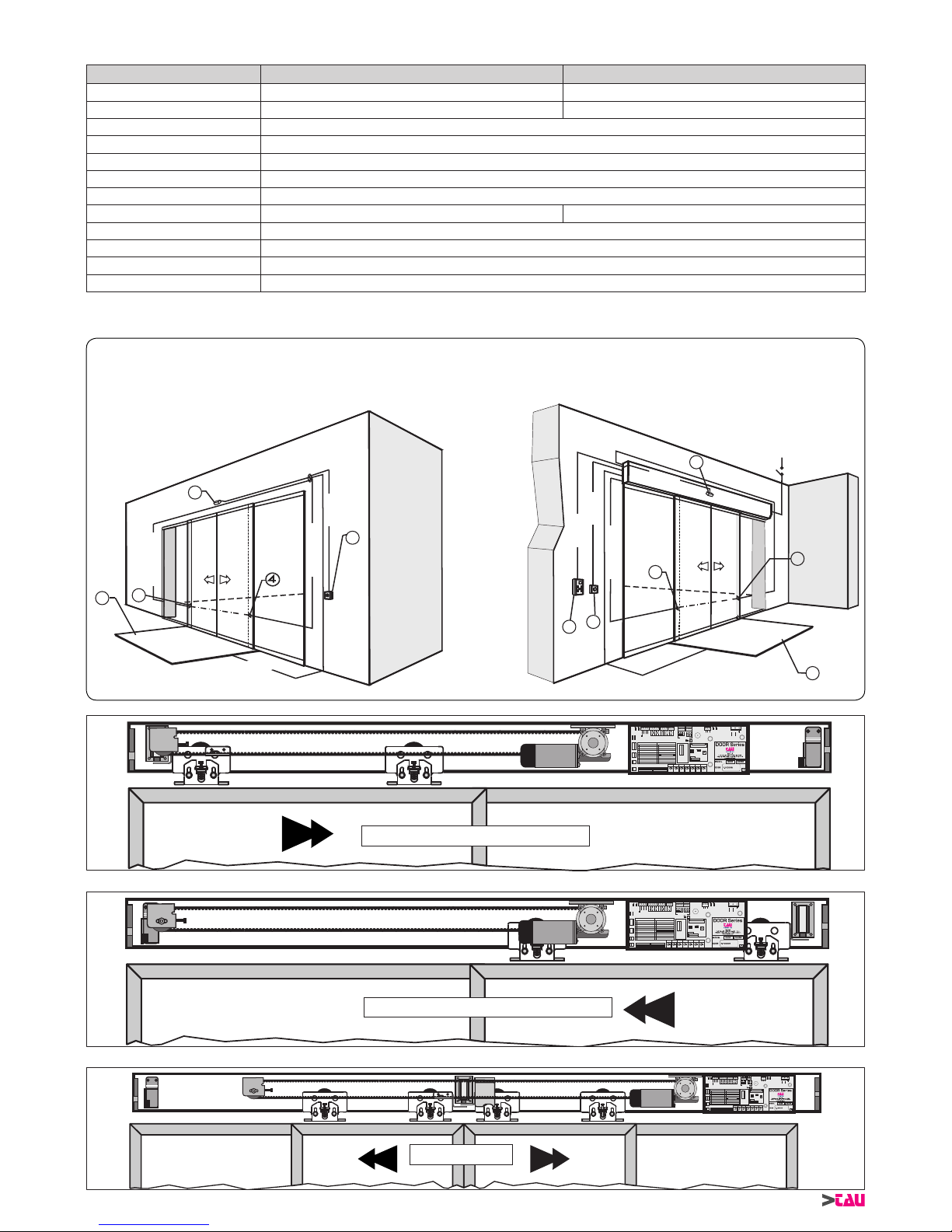
SINGLE LEAF – Right hand
1 INFRARED SENSOR
2 EMERGENCY BUTTON
3 KEYPAD FOR PROGRAMMING
4 PHOTOCELL (FT=transmitting ph., FR=receiving ph.)
5 MAGNETIC FOOTBOARD
6 KEYLOCK SELECTOR
ANTA FISSA
FIXED WING
VANTAIL FIXE
FEST TÜRFLÜGEL
HOJA FIJA
minidip sRminidip sQlockR
motore
lockQ
encoder
battery
f•š•†ˆ’’N R „ššŒœ„š„
f•š•†ˆ’’N S „ššŒœ„š„
switch
start
modulo fotocellule
carica batteria
wd
buzzer
T U V W X Y QP QQ QR QS QT QUQ R S
fotocellule
capN rx capN tx
frSfrRfrQvccgnd ftSftRftQ
K
encQ
encR
QRv
dato
P
comune
start
interblocco
emergenza
radar estN
comune
sensore latN
fotocellula
aux Q
radar intN
apN pedonale
comune
J f›”¡Œ•”ˆ –•˜š„ š„Š’Œ„‰›•†•
J a›š•“„¡Œ•”ˆ “•‡ˆ’’• doorx
minidip sQ
minidip sR
i” ‰›”¡Œ•”ˆ ”•ššˆ –•˜š„ …’•††„š„
e“ˆ˜Šˆ”¡„ „–˜ˆ Œ” ‰›”¡Œ•”ˆ ”•ššˆ
f›”¡Œ•”ˆ …„”†„ H…’•††„ ™ˆ“–˜ˆI
a”šŒ–„”Œ†• ”ˆ’’ˆ ‰›”¡Œ•”Œ ŠŒ•˜”•
a–ˆ˜š›˜„ †•” …„ššˆ˜Œ„ ‡„””ˆŠŠŒ„š„
r„‡„˜ „ššŒœŒ Œ” “„”†„”¡„ ˜ˆšˆ
cŒ†’• †•”šŒ”›• H™•’• –ˆ˜ šˆ™šI
a–ˆ˜šN t•šN d•–• Q¹ Œ” Œ”œˆ˜”„’ˆ
Q
R
S
T
U
V
W
X
Y
QP
i”†˜ˆ“N a›š•“N tˆ“–• ‡Œ –„›™„
f›”¡Œ•”„“ˆ”š• †•” ™ˆ’ˆšš•˜ˆ
f›”¡Œ•”ˆ –„™™•M–„™™•
J p•˜š„ „‡ Q „”š„ „–ˆ˜šN œˆ˜™• dx
m•‡›’• ‰•š•†ˆ’’›’„ Œ”™ˆ˜Œš•
gˆ™šŒ•”ˆ S„ ‰•š•†ˆ’’›’„
rŒ†‹Œ›™›˜„ Œ““ˆ‡Œ„š„
p˜•Š˜„““„¡Œ•”ˆ ‡„ ™ˆ’ˆšš•˜ˆ
sˆšš„ŠŠŒ• Œ”Œ¡Œ„’ˆ
led verde
lampeggiante]
…„ššˆ˜Œ„ Œ” †„˜Œ†„
led verde fisso]
…„ššˆ˜Œ„ †„˜Œ†„š„
QVQW QX
QRv
RTv
RSPv
QRvRTvP
f n
fotocellula Q
fotocellula R
fotocellula S
M
K
QR
Q
R
switch
sensibilita¹
QPa fR
Ua
fQ
Ta
fS
K M
tmQ tmR tmS tmT tmU tmV tmW
Q
R
S
T
U
V
W
X
Y
QP
g
–•šˆ”¡„
„–ˆ˜š›˜„
œˆ’•†Œš적
„–˜ˆ
œˆ’•†Œš적
†‹Œ›‡ˆ
–•šˆ”¡„
†‹Œ›™›˜„
‰˜ˆ”„š„ Œ”
„–ˆ˜š›˜„
„–ˆ˜š›˜„
Œ”œˆ˜”„’ˆ
šˆ“–• ‡Œ
–„›™„
Jdip ‡„ Œ“–•™š„˜ˆ –˜Œ“„ ‡ˆ’ settaggio iniziale
SINGLE LEAF – Left hand
ANTA FISSA
FIXED WING
VANTAIL FIXE
FEST TÜRFLÜGEL
HOJA FIJA
ANTA FISSA
FIXED WING
VANTAIL FIXE
FEST TÜRFLÜGEL
HOJA FIJA
minidip sRminidip sQlockR
motore
lockQ
encoder
battery
f•š•†ˆ’’N R „ššŒœ„š„
f•š•†ˆ’’N S „ššŒœ„š„
switch
start
modulo fotocellule
carica batteria
wd
buzzer
T U V W X Y QP QQQR QS QT QUQ R S
fotocellule
capN rx capN tx
frSfrRfrQvccgnd ftS ftRftQ
K
encQ
encR
QRv
dato
P
comune
start
interblocco
emergenza
radar estN
comune
sensore latN
fotocellula
aux Q
radar intN
apN pedonale
comune
J f›”¡Œ•”ˆ –•˜š„ š„Š’Œ„‰›•†•
J a›š•“„¡Œ•”ˆ “•‡ˆ’’• doorx
minidip sQ
minidip sR
i” ‰›”¡Œ•”ˆ ”•ššˆ –•˜š„ …’•††„š„
e“ˆ˜Šˆ”¡„ „–˜ˆ Œ” ‰›”¡Œ•”ˆ ”•ššˆ
f›”¡Œ•”ˆ …„”†„ H…’•††„ ™ˆ“–˜ˆI
a”šŒ–„”Œ†• ”ˆ’’ˆ ‰›”¡Œ•”Œ ŠŒ•˜”•
a–ˆ˜š›˜„ †•” …„ššˆ˜Œ„ ‡„””ˆŠŠŒ„š„
r„‡„˜ „ššŒœŒ Œ” “„”†„”¡„ ˜ˆšˆ
cŒ†’• †•”šŒ”›• H™•’• –ˆ˜ šˆ™šI
a–ˆ˜šN t•šN d•–• Q¹ Œ” Œ”œˆ˜”„’ˆ
Q
R
S
T
U
V
W
X
Y
QP
i”†˜ˆ“N a›š•“N tˆ“–• ‡Œ –„›™„
f›”¡Œ•”„“ˆ”š• †•” ™ˆ’ˆšš•˜ˆ
f›”¡Œ•”ˆ –„™™•M–„™™•
J p•˜š„ „‡ Q „”š„ „–ˆ˜šN œˆ˜™• dx
m•‡›’• ‰•š•†ˆ’’›’„ Œ”™ˆ˜Œš•
gˆ™šŒ•”ˆ S„ ‰•š•†ˆ’’›’„
rŒ†‹Œ›™›˜„ Œ““ˆ‡Œ„š„
p˜•Š˜„““„¡Œ•”ˆ ‡„ ™ˆ’ˆšš•˜ˆ
sˆšš„ŠŠŒ• Œ”Œ¡Œ„’ˆ
led verde
lampeggiante]
…„ššˆ˜Œ„ Œ” †„˜Œ†„
led verde fisso]
…„ššˆ˜Œ„ †„˜Œ†„š„
QVQW QX
QRv
RTv
RSPv
QRvRTvP
f n
fotocellula Q
fotocellula R
fotocellula S
M
K
QR
Q
R
switch
sensibilita¹
QPa fR
Ua
fQ
Ta
fS
K M
tmQ tmR tmS tmT tmU tmV tmW
Q
R
S
T
U
V
W
X
Y
QP
g
–•šˆ”¡„
„–ˆ˜š›˜„
œˆ’•†Œš적
„–˜ˆ
œˆ’•†Œš적
†‹Œ›‡ˆ
–•šˆ”¡„
†‹Œ›™›˜„
‰˜ˆ”„š„ Œ”
„–ˆ˜š›˜„
„–ˆ˜š›˜„
Œ”œˆ˜”„’ˆ
šˆ“–• ‡Œ
–„›™„
Jdip ‡„ Œ“–•™š„˜ˆ –˜Œ“„ ‡ˆ’ settaggio iniziale
DOUBLE LEAF
3x1,5
230V~
Page 5
5
DOOR Series -
English
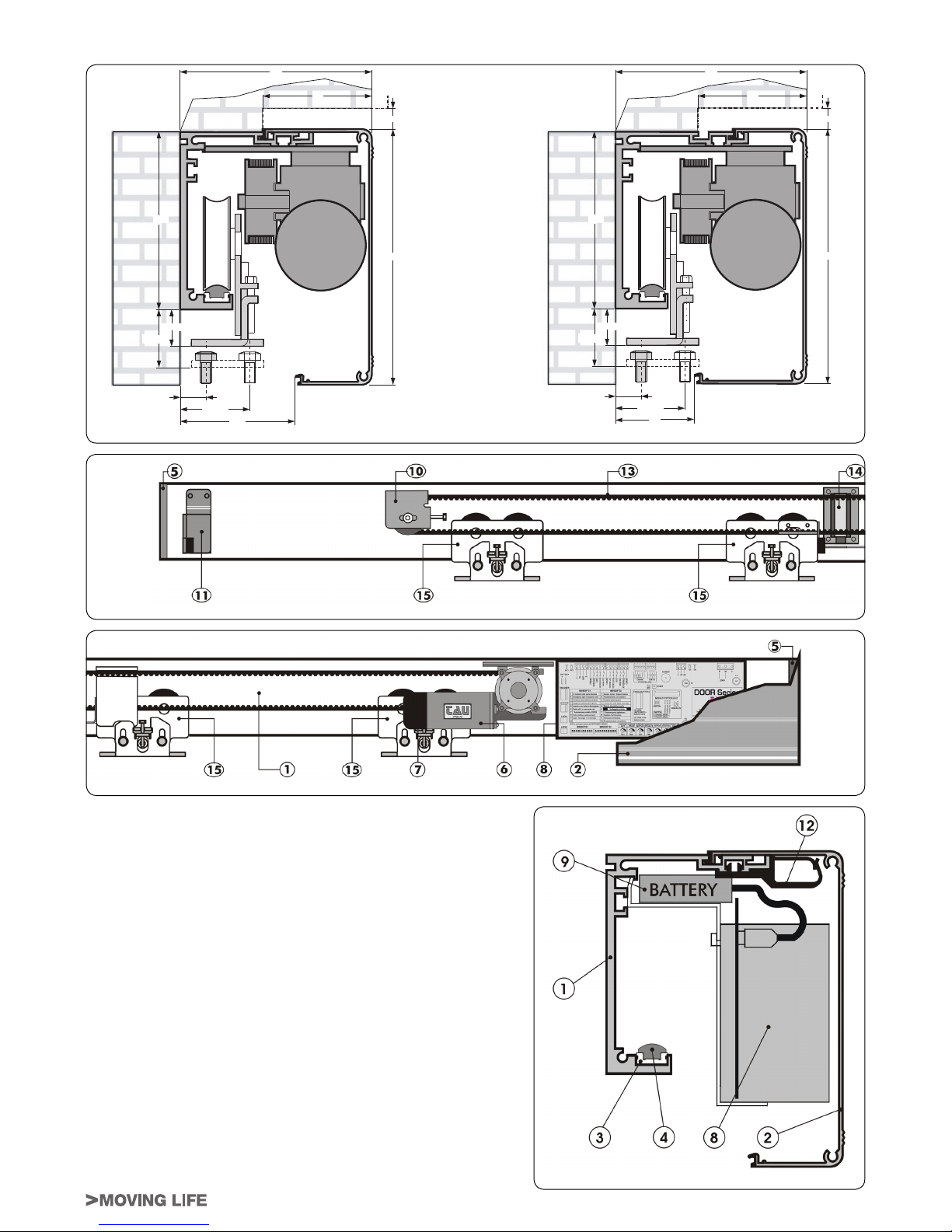
1 Aluminium crosspiece
2 Aluminium cover
3 Sound insulating polyzene guide
4 Aluminium sliding track
5 Sides
6 Gearmotor
7 Encoder
8 Electronic equipment with transformer
9 Battery
10 Snub pulley
11 Brake bumper
12 Cable guide
13 Timing belt
14 Electric block
15 Carriages
g. 2
3_ AUTOMATION SECTION AND REFERENCES
QSU
QXP
c‘‡ƒ—ƒ“…‡ ˆ”— ‰šƒ—† ”•‡“‹“‰
XR
QS
RV min
TQ max
QRU
TY max
XP
QX min
QSU
c‘‡ƒ—ƒ“…‡ ˆ”— ‰šƒ—† ”•‡“‹“‰
XR
RV min
TQ max
QRU
TY max
VP
QX min
QXP
QS
g. 4
g. 3
g. 5
Page 6
6
DOOR Series -
English
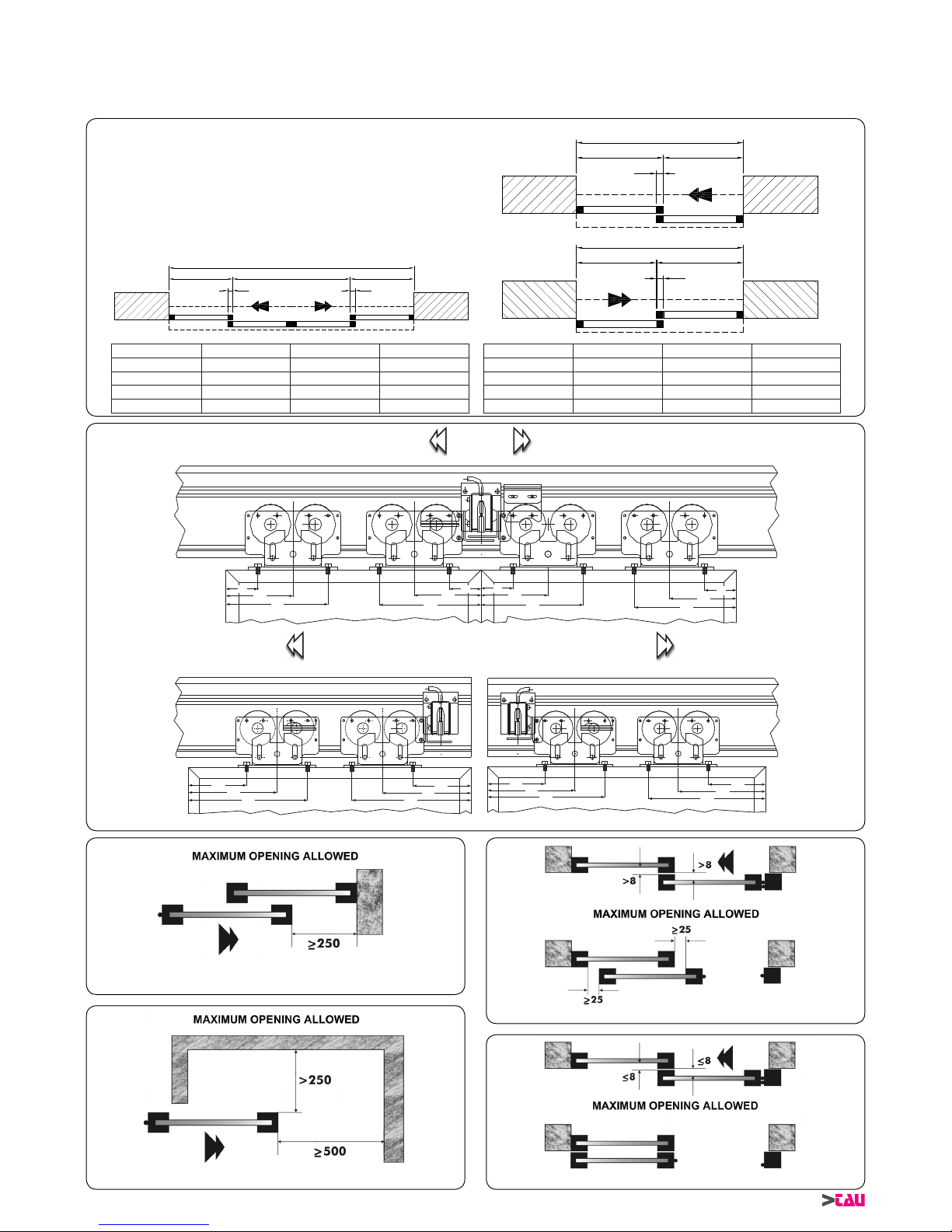
4_ LEAF DIMENSIONS AND STANDARD REFERENCES
For proper door operation, the carriage centre distances and the distance between the carriages and the end of the door frame must
be observed, as shown in gure 6.
Refer also to gures 7, 8, 9 and 10 regarding the safety clearance regulations to be observed.
LT Crosspiece length
S Leaf overlap
X Leaf length
Y Pass-through opening
LT S X1 Y1
1600 mm 50 mm 450 mm 700 mm
1600 mm 25 mm 437,5 mm 725 mm
2000 mm 50 mm 550 mm 900 mm
2000 mm 25 mm 537,5 mm 925 mm
LT S X2 Y2
1600 mm 50 mm 875 mm 725 mm
1600 mm 25 mm 862,5 mm 737,5 mm
2000 mm 50 mm 1075 mm 925 mm
2000 mm 25 mm 1062,5 mm 937,5 mm
LT
X2
Y2
S
LT
Y2
X2
S
LT
Y1
X1
S
X1
S
UP
QPU
QVP
UP
QPU
QVP
UP
QPU
QVP
UP
QPU
QVP
QPU
QVP
RQU
QPU
QVP
RQU
QPU
QVP
RQU
QPU
QVP
RQU
g. 6
g. 7
g. 10g. 9
g. 8
Open
P-10DOOR P-10DOORX
Open Open
Page 7
7
DOOR Series -
English
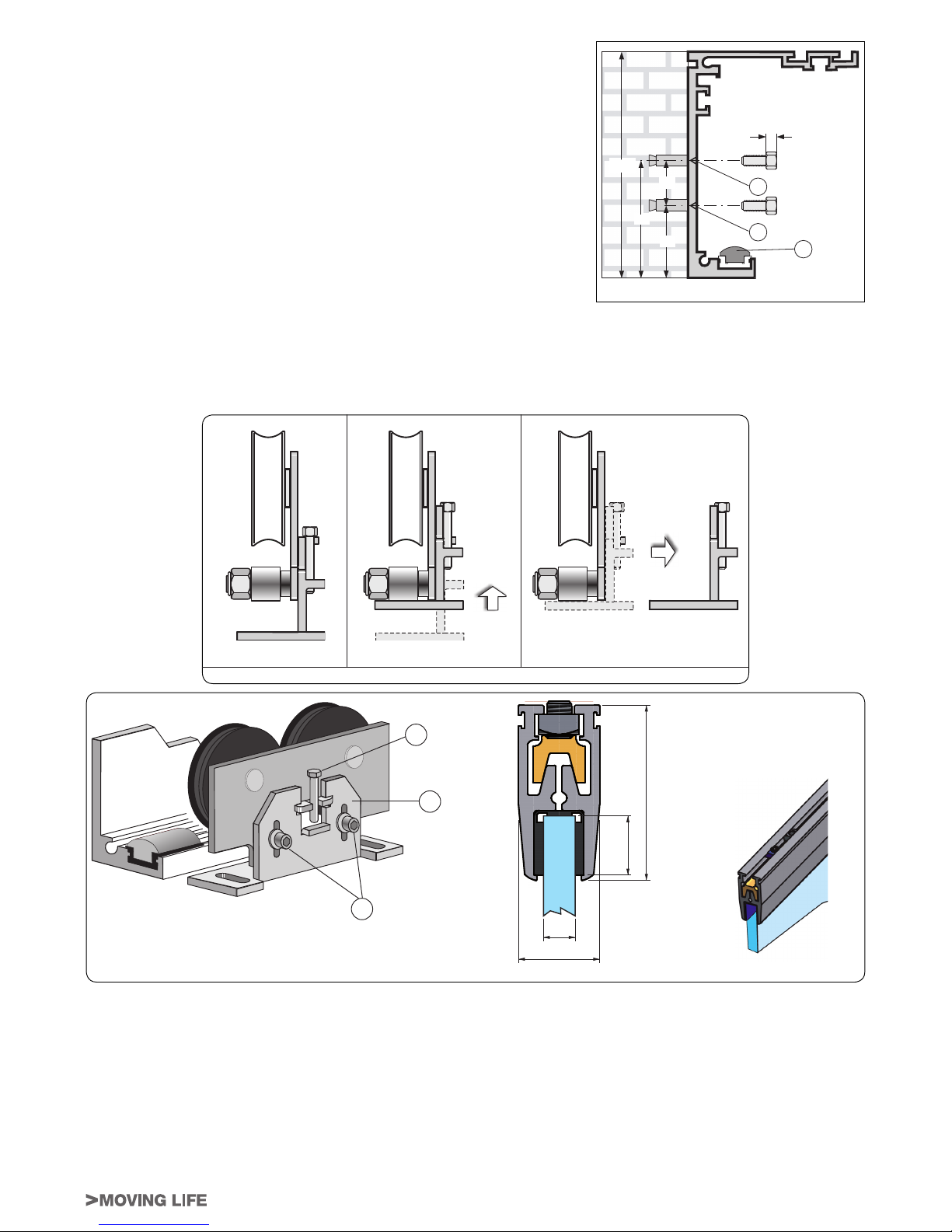
5_ CROSSPIECE ANCHORING (g. 11)
The transom must be xed to a straight surface solid enough to bear the weight of
the wing used. If the wall or bearing surface fail to comply with these parameters, an
adequate iron tube must be installed as the transom is not self-supporting.
It is advisable to use a level to prevent the transom being mounted out of square.
Fix the transom to the wall or bearing surface with M6 steel expansion plugs or
equivalent.
The xing points must be distributed alternately between the two reference lines on the
beam (L1 and L2), every 600 mm.
Make sure that the track (B1) is not damaged when the beam is drilled as this
would impair the way the automation works and prevent it from operating
silently.
Once the beam has been xed, clean the drilling waste from the sliding zone with a
brush or small vacuum cleaner.
6_ ANCHORING THE LEAVES TO THE CARRIAGES AND MAKING
ADJUSTMENTS
Loosen and remove the two screws (A) in each carriage and pull out the removable part
(C) by sliding it upward and then outward as shown in gure 12. Fasten the removable part (C) to the door frame at the distance shown
in g. 6. Now the leaf can be hung: perform the operations described in gure 12 in the reverse order. Now re-position the screws ( A ) in
their seats without tightening them. Once the desired height of the leaf has been adjusted using the adjusting screw (B) tighten the two
screws rmly (A). The horizontal adjustment of the leaf is made by means of the slots found in the movable part of the carriage.
For proper operation of the automation the moving leaf must be perpendicular to the crosspiece.
g. 11
QRU
VU
max X““
bQ
lR
TU
RP
lQ
g. 12
1 2 3
g. 13
Groove for glass
a
b
c
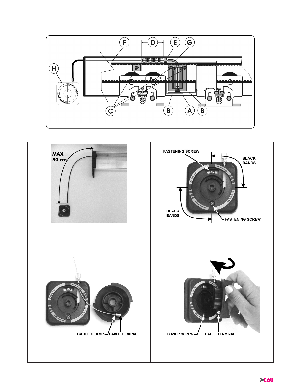
7_ MOUNTING AND ADJUSTING THE ELECTRIC BLOCK AND THE MANUAL EMERGENCY RELEASE DEVICE
If there is no door locking solenoid (optional) go straight on to the next chapter, otherwise strictly comply with the following instructions:
Important: the following operations must be carried out in the absence of mains voltage and with the battery disconnected!
Move the wings to the closed position by hand and make sure that the mobile part A of the electro-lock connects the two locking brackets
B on the carriages (there is only one bracket if the door has one wing). If it fails to connect, unscrew the screws C that x the electrolock and move everything to the position in which the locking brackets are able to couple with mobile part A. Check that the distance D
between clamp E and the spring stop is about 45 mm.
Unscrew the screw of clamp E so that the release cable can slide in it. Allow the mobile part A of the electro-lock to drop fully downwards
until it touches the track. Pull the release cable F very slowly until the mobile part A starts to lift. Keeping cable F at a standstill, move
clamp E until it touches the end of tube G and tighten the clamp screw. Repeatedly pull and release cable F to make sure that the mobile
part A is free to drop to the track when the cable is released and that locking brackets B are freed when the cable is taut. After having
18,5
56,5
24
10 min.
11 max.
Page 8
8
DOOR Series -
English
pulled the cable taut from the outlet of tube H so that it remains in this condition but without the mobile part A being lifted, tighten the
screw of clamp I as near as possible to adjuster L. Regulate this adjuster until the releasing wire is taut. Release ring N can now be
xed with clamp M at the required height. In doors with one wing that open towards the right, the position of the components is directly
opposite to the ones shown in the drawing, but the operations to carry out are exactly the same.
g. 14
At this stage, the H release device must be prepared as follows (wall mounted):
Locate the exact point on the wall where the device is to be mounted,
bearing in mind that the standard cable sheathing is 50 cm long
(a kit
containing a 300 cm length sheath + cable is also available).
Drill a hole in the wall, and fasten the base of the release
mechanism using special screws. Attach the adhesive label as
shown in the gure, making sure the four black bands correspond
to the cardinal points.
Insert the adjuster with 2 nuts, one in the relative slit in the plastic
and the other on the outside of it.
Thread the release cable through the bottom slot, then into the
adjustment register. Then place the cable terminal on the release
knob cable clamp.
At this stage, slide the release knob into the base of the mechanism
taking care to keep the cable terminals in the cable clamp seat,
and the knob in the correct position. The cable terminal must
be set just after the lower fastening screw (clockwise) when the
knob is inserted .
1 2
3 4
Page 9

9
DOOR Series -
English
Once the knob has been inserted, fasten the locking screw, insert
the sheath and move the knob to the NOT RELEASED setting.
Only the orange part of the label with the black arrows must be
visible in this position.
Make sure that the system operates correctly by turning the knob
clockwise and keeping the cable taut with the hand.
WARNING: THE KNOB WILL ONLY TURN ABOUT 45-50
DEGREES AND HAS MECHANISMS IN THE FINAL PART,
ALLOWING IT TO REMAIN IN POSITION AFTER BEING
LOCKED.
Apply the supplied label to cover the screw as shown in the gure,
then move the knob back to the NOT RELEASED position.
The cable must now be fastened to the beam, in one of the ways described below:
1_ by using the special slot on the lateral plastic plug (g. 6A);
g. A
2_ from underneath the beam, using the 90° bent guide supplied
(g. 6B). This system is used when there is no room on either
side of the automation.
g. B
In both cases, when the cable from the solenoid is connected to
the one from the release mechanism, make sure that the release
knob is in the NOT RELEASED position, and that the wire and
sheath from the release mechanism are taut. Route both the
cables (naturally in the opposite direction) into the supplied terminal and tighten them both but without activating the solenoid
(the spring on this latter must only compress a few millimeters).
Now strongly tighten the loose terminal and make sure that both
cables remain taut.
If the cables fail to remain taut, regulate the cable tension using
the relative adjuster in the release mechanism.
Lastly, check to make sure that when the release mechanism is operated, the solenoid’s core is raised and able to free
the door, and that when the release mechanism is set back
to the NOT RELEASED position, the solenoid’s core is free
to move up and down without impediments or obstructions
of any type.
The release device can be installed directly on the side of the
mechanism by threading the cable through the slot designed for
this purpose.
Install the device using the same procedure as the wall mounted
device.
5
6
7
8 9
Page 10

10
DOOR Series -
English
8_ POSITIONING THE BRAKE BUMPER
The brake bumpers must be adjusted in such a way that, both during the closing and opening manoeuvres, they will stop the carriages
before the moving leaf hits the wall, frame or any other obstacle. They are also used by the microprocessor to acquire the limit switch
positions if there is a power failure and the battery is not connected.
While adjusting the brake bumper for the opening manoeuvre keep in mind that, except for the rst manoeuvre after a power failure,
during normal operation the moving leaf stops 5 mm before it strikes the bumper.
9_ ADJUSTING THE BELT TENSION
To adjust the tension of the belt, loosen screw A in the idle pulley lightly, then
screw (to tighten) or unscrew (to loosen) hex screw B.
Once the desired tightness has been obtained, tighten screw A rmly.
g. 15
10_ MOTHER BOARD
10.1_ DESCRIPTION OF PARTS
DL1 (ENC1) - DL2 (ENC2): display the signals coming from the encoder sensor.
DL3 (WD): if the LED ashes quickly it means that the main MP1 microprocessor is operating correctly. If the LED is off or ashes
slowly it means that the electronic board is malfunctioning.
DL4 (12V): it displays the presence of 12 Vac voltage on the M5 terminal board.
DL5 (24V): it displays the presence of 24 Vac voltage on the M5 terminal board.
J1, J2 CONNECTORS: connection of supply transformer.
J3 CONNECTOR: DOORPHOTO1 photocells management card (paragraph 12).
J4 CONNECTOR: DOORBATT battery charge card (paragraph 14).
J5 CONNECTOR: ENCODER connection.
J6 CONNECTOR: MOTOR connection.
J7 CONNECTOR: connection of MAIN LOCK1 ELECTRIC BLOCK (paragraph 7).
J8 CONNECTOR (operation 2): DOORIM module activation (paragraph 18).
F1 FUSE: 5A, protection of 230 Vac power supply line.
F2 FUSE: 10A, protection of motor power supply line.
F3 FUSE: 4A, protection of logic card 12V power supply.
g. 16
MINIDIP S2MINIDIP S1
MOTOR
LOCK 1
ENCODER
BATTERY
Photocell 2 activated
Photocell 3 activated
opening
speed
SWITCH
START
PHOTOCELL CONTROL
BATTERY CHARGER
WD
BUZZER
T U V W X Y QP QQ QR QS QT QU
PHOTOCELL
capN rx capN tx
ENC1
ENC2
12V
DATO
0
COMMON
START
INTERLOCK
EMERGENCY
RADAR EXT.
COMMON
LAT. SENSOR
PHOTOCELL
AUX 1
RADAR INT.
PEDESTRIAN
COMMON
* 130 Kg for wing model
MINIDIP S1
MINIDIP S2
Door locked in night function
Emergency opens in night function
Antipanic in day functions
Continuous cycle (just for test)
Full open after 1’ in winter
Q
R
S
T
U
V
W
X
Y
QP
Self adjusting pause time
Step by step function
* One wing towards DX
Photocell FK38 module inserted
Immediate closing
Initial set-up activated
QV QW QX
12V
24V
230V
12V 24V0
F N
PHOTOCELL 1
PHOTOCELL 2
PHOTOCELL 3
-
+
1 2
1
2
SWITCH
SENSITIVITY
10A F2
5A
F1
4A
F3
+ -
TM1 TM2 TM3 TM4 TM5 TM6 TM7
Q
R
S
T
U
V
W
X
Y
QP
LOCK 2
Q R Sg
Opening with damaged battery
Radar activated in a power failure
* Fire door function
Operation with SMB selector
Control of 3rd FK38 photocell
Programming via selector PS1
Bank function (always blocks)
FLASHING
GREEN LED =
battery charging
FIXED GREEN LED =
battery charged
opening
power
closing
power
braking on
opening
winter
opening
hold
time
closing
speed
*DIP switches to set prior to INITIAL SETUP
frS frR frQ vcc gnd ftS ftR ftQ
K
Page 11

11
DOOR Series -
English
11_ ELECTRICAL CONNECTIONS
TERMINAL BOARD M1 (G – 1 – 2 – 3)
G = EARTH
QRv
dato
P
Q R S Tg
1 = 12V DC
2 = DATO
3 = 0
Connection to the selector switch. Connect the selector switch to the control unit using a 4-pole 0.5 mm diameter cable, maintaining
the same correspondence (12V - DATO - 0 - G). The max length of the cable is 50 metres.
To prevent any false displays on the selector switch, keep the connection cable away from sources of electrical disturbance.
TERMINAL BOARD M2 (4 – 5 – 6 – 7 – 8)
4 = COMMON
S YT U V W X
P
common
emergency
start
interlock
radar extN
5 = EMERGENCY input N.C. It opens the door in any condition.
6 = START input (PS1 button) N.O. It opens the door in all conditions except when the selector
switch is in night locking mode ; it is also the only input
that starts the initial setting.
7 = INTERLOCK input N.C. a) Inhibits door opening when the INTERLOCK function
is selected (see INTERLOCK SYSTEM in section 16).
b) Can be used as a STOP button with DIP 7 of S2
OFF.
c) Can be used for connecting a smoke sensor in re
doors, with DIP 7 of S2 ON (see FIRE DOOR
FUNCTIONin section 19)
8 = EXTERNAL RADAR input N.O. It opens the door in all conditions except when the selector
switch is in night locking mode , or in exit only mode
.
TERMINAL BOARD M3 (9 – 10 – 11 – 12)
9 = COMMON
YXQP QQ QR QS QT
com
latN sensor
photocell
aux Q
common
radar intN
rian
adar extN
ck
10 = SIDE SENSOR input N.C. It opens slowly if it detects an obstacle in the safety
clearance areas.
11 = PHOTOCELL input N.C. If it detects an obstacle in the passage during the closing
manoeuvre, it reverses direction and opens.
12 = AUXILIARY input AUX1 N.O.
a) Selects the night lock (contact made) or 2 ways
function (contact broken) with dip 2 of S2 OFF.
- If selector DOORPROGis used, closing of the AUX1
input activates the NIGHT LOCK function, inhibiting
the setting of selector DOORPROG.
b) Selection of the INTERLOCK mode (dip12 of S1
ON) inhibits detection of the INTERLOCK contact on
terminal 7 (contact made), see section16.
c) If mechanical selector DOORSELF is used (dip2 of
S2 ON), the AUX1 input cannot be used for the above
mentioned functions (see section 17).
TERMINAL BOARD M4 (13 – 14 – 15)
13 = INTERNAL RADAR input N.O. It opens the door in all conditions except when the selector
switch is in night locking mode or in input mode only
.
QS QT QUQQ QR
common
tocell
aux Q
radar intN
pedestrian
frS
14 = PEDESTRIAN input N.O.
a)
It opens the door approx. 90 cm for passage in all
conditions, except when the system is in night locking
mode
(the pedestrian opening distance can be
modied only from the DOORPROG selector switch).
b) If the DOORSELF mechanical selector switch is used, the
PEDESTRIAN function is deactivated (
see paragraph
17).
15 = COMMON input
Page 12

12
DOOR Series -
English
TERMINAL BOARD M5 (16 – 17 – 18)
16 = 0 output
QV QW QX
QRv
P QRv RTv
17 = 12V a.c. max 700mA output - Visualized by led DL4 (12V).
18 = 24V a.c. max 400mA output - Visualized by led DL5 (24V).
Power supply for external devices (radar, photocells, etc.)
In case of power failure, no voltage will be present on these terminals.
EARNING: If you need the radar sensors or external photocells to be operational even in the
BATTERY work mode, draw the power supply for the sensors from terminal board M1 between
terminals 1 (+12V) and 3 (0). Maximum current 250mA.
TERMINAL BOARD M6 (F – N – ) Mains power supply
F = 230V a.c. – 50-60Hz input PHASE
RSPv
f
n
N = 230V a.c. – 50-60Hz input NEUTRAL
=
GROUND; connect the ground conductor to the faston located on the control unit’s metal
casing.
- Provide the mains with an omnipolar isolator with contact opening distance of at least 3mm.
- The power supply line must be protected against short circuit and ground leakage.
- Separate the 230V~ power supply line of the control unit from the very low voltage line of the
control and safety accessories.
12_
DOORFOTO1 PHOTOCELL CARD
12.1_ INSERTING THE CARD IN THE CONNECTOR LOCATED ON THE MOTHERBOARD
Insert the photocell card in the appropriate connector on the motherboard (J3).
12.2_ HOW TO DISTINGUISH THE TRANSMITTER CAPSULES FROM THE RECEIVER ONES
Each pair of photocells consists of a receiver capsule and a transmitter capsule, plus a cable equipped with mini connector for quick
and easy replacement. The receiver capsules are square in shape on the side where the connection cable comes out, while the
transmitter capsules are round. An 11-mm diameter hole is required for both, in order to fasten them to the door frame. The cables
are marked TX (for the transmitters) and RX (for the receivers) at both ends.
RECEIVER TRANSMITTER
12.3_ SELECTING THE NUMBER OF PHOTOCELL PAIRS UTILIZED
The photocell card can handle up to 3 pairs of photocells with incorporated self-diagnostic function, including 2 pairs (FT1 /FR1 and
FT2/FR2) for closing safety, while the third pair (FT3/FR3) can be set to one of the following functions using switches 5 and 8 of DIP S2
(see TABLE 2): closing safety photocell, door crash sensor if a crash panic system is used (in this case the power supply to the motor
is disconnected) or as an opening mode input. The self-diagnostic function makes it necessary to set the number of photocell pairs that
are actually used in the system. The selected number of pairs is signalled through the SW1 dip located on the photocell card (see TABLE
1). Ths rst couple of photocells ft1/fr1 has to be installed 1 mt above the ground level; the second couple of photocells (recommended)
ft2/fr2 at 50 cm above the ground level (please see the diagram below).
TABLE 1 TABLE 2
SW1 dip on DOORFOTO 1 photocell card S2 dip on electronic control unit
1 2 5 8
OFF OFF Only FT1/FR1 is active OFF OFF DOORFOTO1 photocell card absent!!
ON OFF
Only FT1/FR1 - FT2/FR2 are
active
ON OFF
DOORFOTO1 card present,
FT3/FR3 = door crash sensor
OFF ON
Only FT1/FR1 - FT3/FR3 are
active
OFF ON
DOORFOTO1 card present,
FT3/FR3 = safe closing manoeuvre
ON ON All pairs are active ON ON
DOORFOTO1 card present,
FT3/FR3 = open command
PHOTOCELL REFERENCE HEIGHTS
RX1TX1
RX2 TX2
1000 mm
500 mm
Page 13

13
DOOR Series -
English
12.4_ CONNECTING THE RECEIVER AND TRANSMITTER CAPSULES
To prevent interference due to direct sunlight, it is advisable to position the receiver sensors on the side most sheltered from the sun’s
rays.
TERMINAL BOARD M7 (FR1 – FR2 – FR3 – VCC – GND)
FR3 = input RECEIVER CAPSULE 3 (BROWN CABLE)
frS frR
frQ
vcc
gnd
K
capN rx
frS
FR2 = input RECEIVER CAPSULE 2 (BROWN CABLE)
FR1 = input RECEIVER CAPSULE 1 (BROWN CABLE)
VCC = + POWER SUPPLY FOR ALL RECEIVER CAPSULES (BLUE CABLES)
GND = - POWER SUPPLY FOR ALL RECEIVER CAPSULES (BLACK CABLES)
TERMINAL BOARD M8 (FT1 – FT2 – FT3 – +)
FT3 = input TRANSMITTER CAPSULE 3 (BROWN CABLE)
K
capN tx
ftS ftR ftQgndc
FT2 = input TRANSMITTER CAPSULE 2 (BROWN CABLE)
FT1 = input TRANSMITTER CAPSULE 1 (BROWN CABLE)
+ = Power supply
POWER SUPPLY FOR ALL TRANSMITTER CAPSULES (BLUE CABLES)
12.5_ TRANSMITTER AND RECEIVER SENSITIVITY ADJUSTMENT
Once the sensors have been positioned, their sensitivity must be regulated by
means of the potentiometer on the board. Proceed in the following way:
1) Calibrate the potentiometer depending on the distance between the
sensors (see gure alongside).
2) The sensitivity is correct if the leds of the sensors selected in the mini dip
are off.
3) If the leds are on, turn the potentiometer slowly towards the maximum
setting until the leds go out.
4) Check to make sure that the relative leds come on when the infrared beam
from the photocells is broken.
12.6_ OPERATING FAULTS
The photocell module constantly checks the photocells to guarantee their
reliable operation. In the event of capsule malfunction, the motherboard emits
one, two or three beeps according to which pair of capsules has generated the
malfunction. Moreover, in order to prevent the automatic door from being locked in the open position and to guarantee its proper closing,
the door slows down during the closing manoeuvre until the normal operation of the photocells has been restored.
12.7_ DOOR STOP WITH STOP BUTTON
A STOP button with N.C. contact can be connected between terminals FT3 and FR3 in order to stop the movement of the door.
In order to exploit this possibility it is necessary to enable FT3/FR3 on the photocell card and to make it operational as a door crash
sensor (see TABLES 1 and 2).
MAX
SENSITIVITY
MINI DIP Sw1
L1 L2 L3
MIN
SENSITIVITY
POTENTIOMETER
AT HALF SETTING
from 2 to 4 meters
MAXIMUM
POTENTIOMETER
SETTING
from 4 to 6 meters
MINIMUM
POTENTIOMETER
SETTING
up to 2 meters
Page 14

14
DOOR Series -
English
13_ THE DOOR PROG SELECTOR SWITCH
Connect the digital selector DOORPROG to connector M1 of the control unit “Door” (paragraph 11).
Exhausted battery and power failure signals
Input status signals
Work program selection
Reduced opening selection
Free functions
Locked functions
The key is used to block the selected functions. The required program can be set with the SET button in the FREE FUNCTIONS
mode. The SET button is not activated in the FUNCTIONS BLOCKED mode and the work program will be the last one to have
been selected. The key is also used to access the remote programming menu via selector DOORPROG (see section 15.3).
Exhausted battery and power failure signals:
If the LED shows a steady light, it means that there is no mains power supply but the battery is charged.
If the LED ashes, it means that there is no mains power supply and the battery is almost exhausted, or it signals also the battery
malfunction status with mains power supply.
If the LED shows a steady or ashing light, it means that there is no communication between the selector switch and the control unit.
In this case, check the connections between the selector switch and the control unit.
Input status signals:
These LED’s indicate the real-time status of the inputs. Refer to TABLE 4 for the meaning of each LED.
Work program selection:
Press centre button
to switch work program. Refer to TABLE 3 for the meaning of each program.
Reduced opening selection
:
Press the button to reduce the clear opening (winter opening mode). If the LED on the button is on, it means that the function is
enabled regardless of the selected work program.
To regulate the winter opening distance by potentiometer TM6 from DOORPROG selector switch (see TABLE 7).
Press the button to obtain a clear opening of approx. 10 cm. (pharmacy opening). If the LED on the button is on, it means that the
function is enabled. To enable the PHARMACY function, set dip 7 of mini-dip S1 in the OFF position (TABEL 5).
TABLE 3
Work programs Active inputs Active safety devices
Two-way trafc
Outgoing trafc only
Incoming trafc only
Doors always open
Night lock
Page 15

1/4
The release is automatic in the event there is no mains voltage and the
door remains open until the power is restored again. If this does not
occur, turn the release knob in the direction of the arrows (clockwise)
until they are covered (the writing UNLOCKED appears) and then
manually operate the leaf or leaves.
To block the leaf or leaves again, turn the release knob in an anti-
clockwise direction until the writing UNLOCKED is hidden (the arrows
appear again). The automation performs an initial operation at low
speed when the power is restored, after which it starts to function
normally.
The manual manoeuvre must ONLY be done with the door stopped and AFTER disconnecting power from the electrical control unit.
N.B.: if your remote control unit (if supplied) starts working badly after a time, or does not work at all, the batteries may be fl at (they can last from
several months to 2/3 years depending on what type is used). This can be seen from the fact that the transmission confi rmation LED gets dimmer
or only turns on for brief moments. Before contacting your fi tter, try exchanging the battery with one from a good transmitter: if this is the reason
for the fault, simply replace the battery with another one of the same type.
If you wish to add a new automated system to your house, contact your fi tter and we at Tau to have the advice of a specialist, the most developed
products on the market, best operation and maximum automation compatibility.
Thank you for reading these suggestions and we trust you are fully satisfi ed with your new system: please contact your fi tter for any further
requirements.
English
INSTRUCTIONS AND WARNINGS FOR AUTOMATIC SYSTEM USERS
CONGRATULATIONS on choosing a Tau product for your automation system!
Tau S.r.l. produces components for automatic gates, doors, barriers and shutters. These include gear motors, control units, radio control devices,
fl ashing lights, photocells and accessories.
Tau products are exclusively made with top quality materials and processes and, as a company, we constantly research and develop innovative
solutions in order to make our equipment increasingly easier to use. We also pay great attention to all details (technology, appearance and
ergonomics). The extensive Tau range makes it possible for your fi tter to choose the product which best meets your requirements.
Tau, however, does not produce your automated system as this is the outcome of a process of analysis, evaluation, choice of materials and
installation performed by your fi tter.
Each automated system is unique, therefore, and only your fi tter has the experience and professionalism required to create a system that is
tailor-made to your requirements, featuring long-term safety and reliability, and, above all, professionally installed and compliant with current
regulations.
An automated system is handy to have as well as being a valid security system. Just a few, simple operations are required to ensure it lasts for
years.
Even if your automated system satisfi es regulatory safety standards, this does not eliminate “residue risks”, that is, the possibility of dangerous
situations being generated, usually due to irresponsible and/or incorrect use. For this reason we would like to give you some suggestions on how
to avoid these risks:
- Before using the system for the fi rst time: ask your fi tter to explain how residue risks can arise and read the instructions and warnings in
the user handbook that your fi tter will have given you. Keep this manual for future use and, if you should ever sell your automated system,
hand it over to the new owner.
- Your automated system carries out your commands to the letter: irresponsible and/or incorrect use may cause it to become dangerous.
Do not use the system if people, animals and/or objects enter its operating area.
- IT IS NOT A TOY! Make sure children do not play near the system and keep the remote control device out of their reach.
- Faults: If you notice any abnormal behaviour, disconnect the system from the power supply immediately and perform the manual release
operation (see fi gure). Do not attempt to repair the door but call in your fi tter: the system will operate manually as it did before installation.
- Maintenance: to ensure long life and totally safe operation, the system required routine maintenance, just like any other piece of machinery.
Establish maintenance times together with your fi tter. Tau recommends a frequency of 6 months for normal domestic installations but this
may vary depending on the intensity of use (always every 3000 work cycles).
N.B.: All controls, maintenance work and/or repairs may only be carried out by qualifi ed personnel.
- Do not modify the plant or the relative programming and adjustment parameters: your fi tter will see to that.
N.B. Final testing, routine maintenance and any repairs must be documented by the fi tter (in the relative spaces) and such documents
kept by the owner of the system (IF THE DOCUMENTS ARE NOT PRODUCED, THE WARRANTY WILL EXPIRE)
.
- Disposal: At the end of system life, make sure that it is demolished by qualifi ed personnel and that the materials are recycled or disposed
of according to local regulations.
- - -- - - - - - - - - - - - - - - - - - - - - - - - - - - - - - - - - - - - - - - - - - - - - - - - - - - - - - - - - - - - - - - - - - - - - - - - - - - - - - - - - - - - - - - - - - - - - -
Page 16

2/4
Data
Date
Datum
Date
Fecha
Descrizione intervento
Description of job
Beschreibung des Eingriffs
Description intervention
Descripción del trabajo
Parti sostituite
Parts replaced
Ersetzte teile
Parties remplacées
Piezas sustituidas
Firma manutentore
Fitter’s signature
Unterschrift des
Wartungsmannes
Signature réparateur
Firma del técnico
Firma utilizzatore
User’s signature
Unterschrift des
Benutzers
Signature utilisateur
Firma del usuario
Page 17

3/4
Data
Date
Datum
Date
Fecha
Descrizione intervento
Description of job
Beschreibung des Eingriffs
Description intervention
Descripción del trabajo
Parti sostituite
Parts replaced
Ersetzte teile
Parties remplacées
Piezas sustituidas
Firma manutentore
Fitter’s signature
Unterschrift des
Wartungsmannes
Signature réparateur
Firma del técnico
Firma utilizzatore
User’s signature
Unterschrift des
Benutzers
Signature utilisateur
Firma del usuario
Page 18

4/4
Data
Date
Datum
Date
Fecha
Descrizione intervento
Description of job
Beschreibung des Eingriffs
Description intervention
Descripción del trabajo
Parti sostituite
Parts replaced
Ersetzte teile
Parties remplacées
Piezas sustituidas
Firma manutentore
Fitter’s signature
Unterschrift des
Wartungsmannes
Signature réparateur
Firma del técnico
Firma utilizzatore
User’s signature
Unterschrift des
Benutzers
Signature utilisateur
Firma del usuario
- - -- - - - - - - - - - - - - - - - - - - - - - - - - - - - - - - - - - - - - - - - - - - - - - - - - - - - - - - - - - - - - - - - - - - - - - - - - - - - - - - - - - - - - - - - - - - - - -
Page 19

15
DOOR Series -
English
TABLE 4
Emergency input Photocell 3 input
Start input Pedestrian opening input
Internal radar input Interlock input
External radar input Side sensor input
Photocell 1 input Auxiliary input
Photocell 2 input
14_ DOORBATT BATTERY OPERATED OPENING DEVICE
Insert the battery charge card in the J4 connector located on the
motherboard (see side gure). Be careful not to insert the connector
with the pins misaligned. Connect the battery, pay attention to the
polarity (red cable = +, black cable = -) with respect to the 2 male
fastons on the motherboard.
The DOORBATT card performs the self-testing of the battery charge
level and features a green LED and a red LED. The green LED ashes
while the battery is charging and shows a steady light when the battery
has been charged and is in holding mode. The red LED ashes if the
battery is exhausted or damaged, with or without mains power supply,
whereas it is constantly on when the battery is charged without mains
power. If both LEDs are on it means that the battery is disconnected.
● Check periodically the battery efciency
● To allow battery reload, batteries must always be connected to the electronic control unit
● The device must be disconnected from power supply when removing the battery
● In case of replacement, use always original batteries (18V, 600mAh).
● The replacement must be carried out by qualied personnel.
● Batteries must be removed before its disposal.
● Batteries contain pollutants, disposal must be performed complying with local rules and regulations.
Battery connector
Battery card connector
Page 20

16
DOOR Series -
English
15_ ADJUSTING THE AUTOMATISM
After having xed the door wings to the rails, make sure that they slide smoothly., then make all the electrical connections described in
section 11 and comply with the INITIAL SETUP PROCEDURE. This operation is OBLIGATORY, since it allows the control unit to acquire
all the data without which it would not be able to operate (door wing weight, limit switches, inertia, etc.).
STRICTLY COMPLY WITH THE FOLLOWING CHAPTER WHEN THIS OPERATION IS CARRIED OUT.
15.1_ INITIALIZATION PROCEDURE (INITIAL SETTING)
WARNING: the initialization procedure is the phase during which the automation learns and samples all the factors which
will affect its subsequent operation. Execute the procedure only after performing the operations described in the previous
chapters.
IMPORTANT: be careful to remove all obstacles from the doorway and from the radar detection range during the initialisation
procedure, otherwise the procedure will fail and will have to be repeated. The door must not be helped manually and the
settings of the potentiometers must not be modied. The initialisation procedure will have to be repeated if any of the following
parameters are modied: leaf travel, leaf weight, opening direction, type of motor (DOORX or DOOR).
1_ Make sure that the mains power source is OFF, then temporarily disconnect the battery-powered opening device DOORBATT if
installed.
2_ Set all the minidips (S1 e S2) at OFF.
3_ If you are using a DOORX, set DIP7 of S1 at ON, otherwise leave it in the OFF position.
4_ If you use the DOORPROG SELECTOR switch, leave DIP SWITCH 2 of S2 in the OFF setting; if you use the DOORSELF
mechanical selector switch, set it to ON. Set the knob of the DOORSELF mechanical selector to trafc in both directions or to
NIGHT LOCK.
5_ If the automation is a RIGHT-HAND OPENING LEAF, set DIP4 of S2 at ON, otherwise leave it in the OFF position.
6_ If the door is a re dor and a smoke sensor is connected to the INTERLOCK input, set DIP 7 of S2 ON, otherwise leave it OFF.
7_ If you have installed the DOOR PHOTO1 PHOTOCELL CARD, set DIP5 of S2 at ON, otherwise leave it in the OFF position.
8_ Check to make sure that potentiometers TM3 (pushing power on opening) and TM4 (pushing power on closing) are set between
halfway and the maximum value.
9_ Power the system and wait for the initial beep to sound.
10_ Disconnect the power supply and wait for 3 seconds.
11_ Set DIP6 of S2 at ON.
12_ Power the system and wait for the double initial beep to sound.
13_ Press the START control (or the PS1 button on the control unit).
The door will begin a Closing / Opening / Closing cycle at slow speed which it must necessarily complete if the initial setup is to be
successful. At the end of a manoeuvre, a long BEEP will indicate that the procedure has terminated correctly.
14_ By leaving DIP 6 of S2 ON, the door thrust can be checked by means of the buzzer. Its effective intensity can be ascertained by
obstructing its movement. This should cause the door to stop immediately and then reverse its direction.
Poteniometers TM3 and TM4 can be used to regulate the door’s pushing power in the opening and closing phases, respectively,
and to calibrate the activation threshold with precision.
A very brief signal from the buzzer during start-up indicates that the pushing force has been well calibrated, while intermittent
signals as the door moves indicate that the pushing force is insufcient.
Set DIP 6 of S2 to the OFF position to inhibit the buzzer signal that indicates limited power.
Once the initialisation procedure has been performed, you can select the work program best suited to the application among the ones
available, you can modify the door speed, change the times and distances etc. There are two ways of performing these operations:
a) directly from the control unit;
b) through remote programming from the selector switch;
15.2_ ADJUSTING THE AUTOMATISM FROM THE CONTROL UNIT
Operate MINIDIPS S1 and S2 to select the programs listed in TABLES 5 and 6.
Operate potentiometers TM1 to TM7 to modify the parameters listed in TABLE 7.
Any regulations that cannot be made from the control unit due to the absence of additional dip switches or potentiometers can be made
only using the DOORPROG digital selector switch.
15.3_ ADJUSTING THE AUTOMATISM THROUGH REMOTE PROGRAMMING FROM THE SELECTOR SWITCH
To enable remote programming, rst of all DlP10 of S2 must be set at ON.
To access the programming mode follow these steps:
a) Set the selector switch’s locking key in the locked functions position .
b) Press and hold down the selector switch’s SET button .
c) Return the locking key to the free functions position .
d) Release the SET button .
e) The inputs LED’s will light up sequentially from left to right to signal the loading of the data (UPLOAD).
Page 21

17
DOOR Series -
English
f) Once the UPLOAD has been completed, the red BATTERY LED and the yellow PHOTOCELL3 LED will light up.
g) The battery LED signals that the S1 MINIDIP is being operated, while the photocell 3 LED signals:
g1) DIP1 of S1 in the ON position if the LED shows a steady light .
g2) DIP1 of S1 in the OFF position if the LED shows a ashing light.
h) To change the status of the DIP (ON -OFF), press the WINTER OPENING button .
i) To go to DIP2 of S1, press the PHARMACY OPENING button .
l) Repeat the last operation above to go to the other DIPS of S1.
m) Refer to TABLES 5 and 6 for the meaning of the DIPS.
n) To operate MINIDIP S2, press the SET button , a POWER LED will light up.
o) Repeat the operations described for MINIDIP S1 to select and change the status of the single DIPS.
p) To go to POTENTIOMETER TM1, press the SET button the 2-WAY trafc LED will light up.
q) When you operate the potentiometers, the inputs LED’s will form a scale to indicate the set value.
r ) To change the value of the selected potentiometer, press:
r1) the WINTER OPENING button to lower the value.
r2) the PHARMACY OPENING button to increase the value.
s) To go to POTENTIOMETER TM2, press the SET button .
t) Repeat the last operation above to go to the other potentiometers.
u) Refer to TABLE 7 for the meaning of the potentiometers.
v) To exit the programming mode and memorize the modied values, proceed as follows:
v1) Set the selector switch’s locking key in the locked functions position .
v2) Press and hold down the selector switch’s SET button .
v3) Return the locking key to the free functions position .
v4) Release the SET button .
v5) The inputs LED’s will light up sequentially from right to left to signal the DOWNLOAD.
v6) Once the DOWNLOAD has been completed, the control unit will emit 2 beeps.
v7) The selector switch will return to normal operation.
z) To exit the programming mode without memorizing the modied values, proceed as follows:
z1) Set the selector switch’s locking key in the locked functions position ;
z2) Return the locking key to the free functions position ,
z3) The selector switch will return to normal operation and the control unit will emit 1 beep.
15.4_ RESET OPERATION
To RESET the control unit without disconnecting the mains power source, proceed as follows: access the programming mode with
selector DOORPROG, follow steps A) to E) in section 15.3, then quit the programming mode by following steps Z1) to Z3) of section
15.3.
Page 22

18
DOOR Series -
English
TABLE 5
Programming from
control unit
Programming from
selector switch
Functions related to the S1 MINIDIP or to LED with programming from the
selector switch
W
O
R
K
P
R
O
G
R
A
M
S
OFF OFF OFF
In the day functions, the electric block is released (powered) and all the control inputs are
enabled. In NIGHT LOCKING mode the door cannot be opened.
ON ON OFF
In the day functions, the electric block is released (powered) and all the control inputs
are enabled. With the DOORPROG selector switch set to the NIGHT LOCKING mode,
the door opens 10” and stays open before re-closing. It can be opened again only via the
emergency input .
OFF ON OFF
In the day functions, the electric block is released (powered) and all the control inputs are
enabled. With the DOORPROG selector switch set to the NIGHT LOCKING mode, the door
can be opened using the emergency input .
OFF OFF ON
Bank function. The door locks the leaves at each closing through the electric block in the
day functions; in the night locking mode the door cannot be opened.
BATTERY OPENING MODE. In the event of a power failure, if the program selector switch
is set to one of the day functions, the door opens and stays open until the power supply has
been restored.
WARNING: if the dip switch is set to OFF, in the event of a power failure the door can be
opened using the emergency input .
BATTERY MONITORING. With the battery exhausted or damaged, the door will open and
stay open in the day functions.
WARNING: if the dip switch is set to OFF and the battery is exhausted or damaged, the
control unit will sound a beep for 1” before performing any opening manoeuvres.
This beep is sounded for the rst 10 manoeuvres starting from detection of the event in the
day functions.
In the event of a power failure, in the battery operating mode the door can be opened via all
the control inputs. To enable the radars to operate in battery mode, the power supply must
be drawn from terminals 1(+) and 3 (-) of the M1 terminal board.
WARNING: if the dip switch is set to OFF and there is a power failure, the door can be
opened only using the EMERGENCY input.
Before performing the initial setting of the control unit, set the parameters for motor management: ON=DOORX; OFF=DOOR.
After completing the initial setting procedure, when the door is in work mode, select the
operating mode for the LOCK2 output:
OFF = PHARMACY function; ON = AIR BLADE or OPEN DOOR INDICATOR LIGHT man-
agement (see paragraph 18).
It activates the cyclic opening function (open and close cycle repeated until the DIP is
switched back to OFF). N.B.: Use this function only for internal testing purposes.
If the door cannot be closed in winter mode due to high trafc, after approx. 1’ it switches to fully open. It will return to winter mode after a complete closing manoeuvre.
With the dip-switch OFF, the door always stops at the winter opening point.
WARNING: Function disabled. Keep the DIP in ther OFF position.
11
Keep in the PFF position!!
This dip is used for resetting the default values of the TECHNICAL MENU (see section
21).
12
Activates the interlock function (see paragraph 16).
It makes the interlock input operational; if this input is engaged, the door can be opened
only via the EMERGENCY button.
Page 23

19
DOOR Series -
English
TABLE 6
Programming from
control unit
Programming from
selector switch
Functions related to the S2 MINIDIP or to LED with programming from the
selector switch
It automatically increases the pause time if the door cannot be closed due to high trafc.
The pause time is kept at a constant value with the dip-switch in the OFF position.
It activates work program selection via the DOORSELF mechanical selector switch (see
paragraph 17).
N.B. keep the DIP switch in the OFF position if you use the DOORPROG digital selector
switch or if a simple switch is used on the AUX1 input to manage the day function (switch
on) or night lock function (switch off).
It activates the STEP-BY-STEP function (an impulse opens, an impulse closes, etc.). With
this function, the active inputs are: emergency and start .
With dip on OFF position, automatic door closing is always enabled.
Set at ON if the automation is SINGLE-LEAF opening to the RIGHT. N.B. With LEFT hand
DOUBLE-LEAF or SINGLE-LEAF, keep the DIP in the OFF position.
For “BLOW / BLOW-X” telescopic doors, set to ON if the device is for a single wing
opening towards.
Together with switch 8 it selects the DOORFOTO1 photocell card (if installed) and the op-
erating mode of photocell FR3/FT3. Refer to TABLES 1 and 2 in chapter 12.3 for instruc-
tions on how to use this switch.
WARNING: keep the dip-switch OFF if photocell DOORFOTO1 is not installed.
N.B. It activates the initial setting cycle. Read carefully the chapter regarding this
operation.
ON = FUNCTION FOR FIRE DOORS (see section 20)
WARNING: Activate the function before making the INITIAL SETUP described in SECTION
15.
OFF =standard function for INTERLOCK input activated as door stop.
Together with switch 5 it selects the DOORFOTO1 photocell card (if installed) and the op-
erating mode of photocell FR3/FT3. Refer to TABLES 1 and 2 in chapter 12.3 for instruc-
tions on how to use this switch.
WARNING: keep the dip-switch OFF if photocell DOORFOTO1 is not installed.
The door closes immediately if the radars and photocells are not activated (the other inputs
work normally).
With the dip-switch OFF, the door carries out a complete opening, pause and closing cycle
on each radar detection.
It activates the programming of the POTENTIOMETER DIPS from the DOORPROG. selector switch. After setting this DIP at ON, execute a complete open and close cycle in order
to activate this function (the dips and potentiometers on the control unit have no effect).
N.B. if this DIP is left at OFF, it will not be possible to switch the position of DIPS 1
to 10 of S1 and S2 and of potentiometers TM1 to TM7 from the DOORPROG selector
switch.
11
Operation of LOCK2 output in the INTERLOCK function (see paragraph 16):
OFF: it is activated 0.5” before the opening of the door;
ON: it is activated at the same time as the door opens.
12
N.B. function not enabled, keep the DIP in the OFF position.
Page 24

20
DOOR Series -
English
TABLE 7
Regulating from
control unit
Regulating from
selector switch
N.B. If the program
symbol is highlighted, it
means the LED is on.
Work parameters
Opening speed max 70 cm/sec
Closing speed max 50 cm/sec
PUSHING FORCE ON OPENING
Increase the value to obtain a stronger pushing force on opening.
PUSHING FORCE ON CLOSING
Increase the value to obtain a stronger pushing force on closing.
BRAKING CURVE ON OPENING
Increase the value to obtain faster braking during the slowing phase on opening.
Winter opening distance: max. 150 cm* , min. 40 cm*
NOTE: the Winter opening distance is never lower than the pedestrian opening
distance, therefore to reduce the Winter opening distance again, the pedestrian
opening distance shall be reduced rst by means of potentiometer TM8.
*for each wing
Pause time: max 20 sec
TM8
Pedestrian opening distance: max 150 cm*, min. 40 cm*
*for each wing
TM9
BRAKING CURVE ON CLOSING
Increase the value to obtain faster braking during the slowing phase on closing.
TM10
REDUCED SPEED
The door moves at this speed if its direction is reversed after having covered a short distance from start-up. This prevents it from moving at an excessively high speed when it
nears the end of travel during the reversing phase.
Page 25

21
DOOR Series -
English
16_ INTERLOCK SYSTEM
g. 17
DIP SWITCH 12 of S1 (see TABLE 5)
ON INTERLOCK function ENABLED
OFF INTERLOCK function DISABLED
DIP SWITCH 11 of S2 (see TABLE 6)
ON
LOCK2 is activated at the same time
as the door opens (to be set on control unit A)
OFF
LOCK2 is activated 0.5” before the
opening of the door (to be set on
control unit B)
PT5
PT6
DL1 DL2
G 1 2 3
4 5 6 7 8 9 10 11
R2
R3
RS1
- +
~ ~
C8
C7
C6
C9
-+
BAT
ENCODER
MOTORLOCK1LOCK2
-
+
BATTERY CHARGER
MFT1
MFT3
MFT4
MFT2
IC2
IC3
R8
R9
SPEED
ONON
S1
S2
TM1
-
+
-
OPEN
PT5
PT6
DL1 DL2
G 1 2 3
4 5 6 7 8 9 10 11
R2
R3
RS1
- +
~ ~
C8
C7
C6
C9
-+
BAT
ENCODERMOTORLOCK1LOCK2
-
+
BATTERY CHARGER
MFT1
MFT3
MFT4
MFT2
IC2
IC3
R8
R9
SPEED
ONON
S1
S2
TM1
-+-
OPEN
CONTROL UNIT “A” CONTROL UNIT “B”
The diagram shows a connection between two control units that control two automatic doors in the INTERLOCK conguration. Plug
module DOORIM (see paragraph 18) into the control units’ LOCK2 connector.
Terminal “-” of the DOORIM module coupled to control unit “A” must be connected to terminal 7 (interlock input) of control unit “B” and
vice-versa.
Terminals 4 of both control units must be connected to each other.
The DOORPROG digital selector switch is required.
Set dip switch 12 of S1 on both control units to ON, so as to enable the interlock function.
Next, set dip switch 11 of S2 to ON on control unit “A”, and set the same dip switch to OFF on control unit “B”.
When one of the two control units receives an opening command, it reads the status of the interlock input (to check whether it is enabled
to start) and it simultaneously sends a locking signal to the other control unit (via the LOCK2 output) before it proceeds with the opening
manoeuvre.
The START input on terminal 6 is used by both control units for connection of a radar or common footboard, for instance for presence
detection between the rst and second doors in a short hallway.
While the rst door is closing, and for 5 seconds after completion of the closing manoeuvre, the START input is ignored in order to enable the moving door to shut completely and enable the second door to open while preventing access through the rst.
If you wish to open the door immediately upon completion of the closing manoeuvre, connect the opening device on the PEDESTRIAN
input to terminal 14, which, in the interlock conguration, commands total opening rather than partial.
With the interlock input engaged, the door can be opened only by using the EMERGENCY button at terminal 5.
By connecting a switch on the AUX1 input at terminal 12, and closing the contact, the detection function can be disconnected on the
interlock input, thus enabling free passage.
By re-opening the contact on AUX1, the operating mode with interlock function is restored.
If you wish to install a closed-door detection device (microswitch, magnetic reed, etc.) for additional system security, you need to connect the N.C. contact in series between terminal “-” of LOCK2 and the control unit’s INTERLOCK input.
Page 26

22
DOOR Series -
English
17_ DOORSELF MECHANICAL SELECTOR SWITCH
The DOORSELF mechanical selector switch allows you to set the work program of the automatic DOOR. To enable its operation, position dip switch 2
of S2 at ON (see TABLE 6).
WARNING: If you use the DOORSELF mechanical selector switch, the
AUX1 and PEDESTRIAN inputs of the DOOR control unit will lose all their
functions described in paragraph 11.
The DOOR control unit, enabled for operation with the DOORSELF mechanical selector switch, must use the software version of the main
microprocessor MP1 R.4.5 or a higher version.
17.1 – ELECTRICAL CONNECTIONS
TERMINAL 1 = connect to input 13 (INTERNAL RADAR) of the DOOR
control unit;
TERMINAL 2 = connect to input 9 (COMMON) of the DOOR control unit;
TERMINAL 3 = connect to input 12 (AUX1 auxiliary) of the DOOR control
unit;
TERMINAL 4 = connect to input 14 (PEDESTRIAN) of the DOOR control
unit.
17.2 – OPERATING MODE
Rotate the DOORSELF selector knob to select the desired function among
the ve available ones:
DOOR ALWAYS OPEN = to keep the door completely open.
If you start opening the door by setting the selector switch to the WINTER OPENING mode, and then immediately turn the knob to
the DOOR ALWAYS OPEN position, the door will stop in the winter opening position.
WINTER OPENING = used to reduce the opening size.
TWO-WAY TRAFFIC = used to open the door via all the control inputs.
OUTBOUND TRAFFIC = used to override inbound trafc detection (EXTERNAL RADAR).
NIGHT LOCK = used to keep the door closed, allowing it to be opened only via the EMERGENCY input.
18_ DOORIM MODULE
The DOORIM module is an optional interface card designed for management of
the functions described below.
It has a relay output with dry contact (terminals 1-2), which can be N.O. or N.C.
type (depending on the position of jumper J1) and an OPEN COLLECTOR type
signal output “-”.
The DOORIM module must be plugged into the LOCK2 connector of the
Door control unit.
• AIR BLADE
Position dip switch 7 of mini-dip S1 at ON.
Use the dry contact on terminals 1 and 2 of the DOORIM module to command
an air blade, i.e. a device that generates a ow of cold or heated air to separate the temperature outside from that inside. The output is active when the
door is moving or open, it is deactivated when the door is closed.
• OPEN DOOR INDICATOR LIGHT
Position dip switch 7 of mini-dip S1 at ON.
Use the dry contact on terminals 1 and 2 of the DOORIM module to power an
indicator light signalling the door status. The output is active when the door is
moving or open, it is deactivated when the door is closed.
• INTERLOCK FUNCTION (see paragraph 16)
Connect terminal “-” (OPEN COLLECTOR output) of the DOORIM module to the interlock input (terminal 7) of the second control
unit.
g. 18
M1
1 2 3 4
SM
0419
44
80
80
g. 19
J1
J1
NC*
NA**
NC NAJ1
- 1 2
UR1
* N.C. contact between terminals 1-2.
** N.O. contact between terminals 1-2.
Page 27

23
DOOR Series -
English
19_ FIRE DOOR FUNCTION
The DOOR device has a specic function for use on re doors.
Connect a smoke sensor with N.C. Contact on the INTERLOCK input to terminal 7 to obtain forced door closing at slow speed after
detection by the sensor. None of the control and safety inputs will be activated during this closing manoeuvre. To enable the function, set
DIP 7 of S2 ON before making the initial setup. After this, it will not be possible to deactivate the function by simply switching the status
of the DIP. It will be necessary to make a new initial setup.
After re-closing caused by smoke sensor detection, the door can only be re-opened by means of the EMERGENCY input (terminal 5),
which will act in the impulsive mode if the sensor no longer detects the smoke alarm condition or in the CONSTANT PRESSURE mode
if the sensor continues to indicate the presence of smoke.
20_ MEANING OF BUZZER SIGNALS (BEEPS)
5 BEEPS = door not set.
5 BEEPS – 0.5” pause -1 BEEP = ENCODER not operating correctly.
4 BEEPS = activation of PHOTO 3 as door crash sensor.
2 BEEPS = exit from programming procedure from DOORPROG selector switch with data memorization.
1 BEEP = exit from programming procedure from DOORPROG selector switch without data memorization.
1 BEEP = obstacle detection in the event of collision, followed by a reversal manoeuvre.
1, 2, 3 BEEPS = self-diagnosis failed at photocells 1, 2, 3 respectively (the signal is given at the starting of each
manoeuvre).
1 prolonged BEEP (5”) = initial setting completed.
1 long BEEP (1”) = battery failure signal followed by opening of door.
Series of rapid BEEPS = insufcient pushing power (check the settings of TM3 and TM4)
21_ ADVANCED FUNCTIONS - TECHNICAL MENU
The adjustments in the technical menu allow you to change the various door operating parameters. This is of use when the default
settings are not the optimal ones.
Selector DOORPROG must be available for access to the TECHNICAL MENU.
Turn the to the horizontal function locking position, press the two key and , and keep them depressed, then turn the key back to
the vertical work position.
The yellow leds will come on in sequence from left to right, showing that data are being loaded. After this, the red battery led and the
yellow led of photocell 3 will come on.
The keypad will now be operating on dip-switch 1 of switch S1, thus in the basic adjustments phase described in the main instructions
provided for the door.
Press the SET key 11 times several times to go to the end of the basic regulations
Described in tables 5, 6 and 7 of the main instructions, i.e. Low speed.
This situation coincides with the beginning of the TECHNICAL MENU.
Transmit a pulse to the SET key to access the point 1 adjustment option:
similarly to the previous adjustments, the yellow leds form a scale that indicates the value entered.
Press the key to decrease, or the key to increase this value.
1) ACCELERATION CURVE ON OPENING
This is the door’s acceleration thrust during the opening phase so as to reach the normal speed calibrated by
TM1.
Acceleration is faster if the value is increased.
Press the SET key to access the point 2 adjustment option.
2) ACCELERATION CURVE ON CLOSING
This is the door’s acceleration thrust during the closing phase so as to reach the normal speed calibrated by
TM2.
Acceleration is faster if the value is increased.
Press the SET key to access the point 3 adjustment option.
3) BRAKING CURVE ON REVERSAL
This is the braking intensity during wing travel, before the direction is reversed.
Braking is faster if the value is increased.
Press the SET key to access the point 4 adjustment option.
4) SLOWING DISTANCE ON OPENING
This is the slowing distance on opening before end of travel.
Increase the value to obtain a greater slowing distance.
Press the SET key to access the point 5 adjustment option.
Page 28

24
DOOR Series -
English
5) SLOWING DISTANCE ON CLOSING
This is the slowing distance on closing before end of travel.
Increase the value to obtain a greater slowing distance.
Press the SET key to access the point 6 adjustment option.
6) END OF TRAVEL DISTANCE ON OPENING
This is the distance between the end of travel on opening and the nal resting point or mechanical stop.
Increase the value to increase the distance between the end of travel and the mechanical stop.
Press the SET key to access the point 7 adjustment option.
7) END OF MANOEUVRE PUSHING POWER ON CLOSING
This is the power of the thrust exercised by the motor in the last slowing section on closing. It is useful for preventing friction from the LOCK from activating the obstruction detector and preventing the actual door itself from
completely closing on the nal stop point.
Increase the value to increase the pushing power.
Press the SET key to access the adjustment option described in point 8.
8) UPKEEP VOLTAGE ON CLOSING
This is the pushing force of the door when it is at a standstill, thus allowing the wings to always remain rmly
closed.
Increase the value to increase the upkeep voltage with which the motor is supplied.
Press the SET key to access the adjustment option described in point 9.
9) END OF MANOEUVRE PUSHING TIME ON CLOSING
This is the time during which the motor continues to push in the last slowing section on closing. It allows the door
to completely move towards the closing position by overcoming any friction.
Increase the value to obtain a longer pushing time.
Press the SET key to access the adjustment option described in point 10.
10) PHARMACY OPENING DISTANCE
This is the opening distance of the door when the PHARMACY function is enabled in digital selector DOORPROG.
Can be adjusted from 5 to 25 cm per wing.
Press the SET key to access the adjustment option described in point 11.
11) OBSTRUCTION RESPONSE DELAY
This is the response time when an obstacle causes the door to reverse after an impact. Increase this value to
obtain a longer intervention delay. This is useful for distinguishing an effective obstacle from brief friction from
the lock during door wing travel.
Press the SET key to access the adjustment option described in point 12.
12) OPERATING DISTANCE AT SLOW SPEED
This is the part in which the door moves at the reduced speed set by potentiometer Tm10 if the door’s direction
reverses after it has moved a brief distance from the starting point. This allows the door to move a short distance
in reverse in a smooth and linear way without sharply accelerating.
Increase the value to obtain a greater operating distance in the slow speed.
The adjustments that can be made via the TECHNICAL MENU have now terminated. The programming phase can thus be quitted and
the data memorized in the following way:
a) turn the key to the horizontal blocked position;
b) press the SET key and keep it depressed;
c) turn the key back to the vertical position and release SET;
d) the yellow leds will ash from right to left to indicate that the data are being downloaded;
e) at the end of this process, the control unit will issue 2 bips to indicate that the data are being memorized.
If you do not wish to memorize the changes, quit the programming mode by simply turning the key of the DOORPROG selector
horizontally and move it back to the vertical position. The control unit will issue one single bip to show that the previous settings have
not been changed.
IMPORTANT!!
If the door fails to operate in the desired way after any one of the parameters in the TECHNICAL MENU has been changed and
you wish to return to the original operating mode, proceed as described below:
a) access the programming mode by means of the DOORPROG selector;
b) set dip-switch 11 of switch S1 to the ON position;
c) quit the programming mode and memorize the data. The control unit will issue 2 bips to indicate that the default values
have been activated again.
Page 29

25
DOOR Series -
English
22_ TROUBLES, CAUSES and CURE
ATTENTION!
It is advisable to have always the digital selector DOORPROG at disposal during each servicing intervention on the automatic
door (even if the mechanical selector DOORSELF is physically installed), in order to display the input state through the pilot
lamps and to gain access to the advanced regulations of the technical menu, which are possible only with the help of the
digital selector DOORPROG.
TROUBLE PROBABLE CAUSE CURE
The control unit emits 5 beeps and the door
does not move.
The control unit has not been initialized
(initial setup).
Perform the initial setup procedure described
in para. 15 of the installation manual.
During the initial setup procedure, the motor
cannot move freely and the control unit
emits 2 beeps.
Fuse F2 could be burnt. Replace the 10A fuse F2.
A door frame friction could stop the door
movement.
Regulate the door frame and check that the
door can slide.
During the initial setup procedure, the motor
does not move.
The control and safety inputs are not
connected correctly.
Check the electrical connections on control
and safety inputs.
Control or safety inputs are busy.
Remove any obstacle from the radar or
photocell detection range.
With the mechanical selector DOORSELF,
the door cannot end the initial setup
procedure.
The mechanical selector DOORSELF knob
is in the winter opening position.
Place the mechanical selector DOORSELF
knob on two-way trafc position or on NIGHT
LOCK position.
The control unit does not reply to the dipswitch or potentiometer changes.
The dip 10 of S2 is on ON (setting from
digital selector DOORPROG)
Perform the desired changes using the
digital selector DOORPROG, or move the
dip 10 of S2 on OFF, carry out a complete
opening/closing cycle and then make the
desired settings.
The door emits a beep before opening. The battery is defective or disconnected.
Check the battery connection and the
efciency of the battery antipanic system
DOORBATT.
The door opens but does not close.
The radar or the photocell sense a
presence.
Check that the radars or the photocells are
not engaged or defective.
The dip 5 of S1 is ON and the battery is
disconnected or defective.
Check the efciency and the connection of
the battery antipanic device.
The door stops during the sliding movement
and then slides in the opposite direction.
In the following maneuver the movement is
slower.
The door detects and obstacle along the
stroke.
Find the obstacle and remove it.
The door frame has frictions that are
considered as an obstacle.
Regulate the door frame and, if necessary,
increase the value in item 11 of the
“INTERVENTION DELAY with OBSTACLE”
Technical Menu with the digital selector
DOORPROG.
The door moves jerkily and with difculty. The motor thrust power is insufcient.
Increase TM3 potentiometer value (opening
thrust power) and TM4 potentiometer value
(closing thrust power).
The door opens for a short part of the stroke
and closes slowly.
The encoder connector is disconnected or
the encoder is damaged.
Check the 4-pole connector connection and
that control unit ENC1 and ENC2 leds are
on, by manually moving the door.
The control unit emits 6 beeps and the door
moves of a few centimeters.
Encoder not working.
Check the encoder cable connection, if
necessary replace the encoder.
The photocell module DOORFOTO1 is on,
the photocell capsules are connected, but
the control unit does not detect them, or
signals autodiagnosis failed by the control
unit beep.
Dip 5 and dip 8 of dip switch S2 are OFF.
Set dip 5 or dip 8 of S2 on ON to enable the
photocell module DOORFOTO1.
Dip 1 and dip 2 of the photocell module
DOORFOTO1 are not correctly selected.
Set dip 1 and dip 2 of the photocell module
DOORFOTO1 according to the number of
capsules used.
The electrical connection of the photocell
capsule is wrong.
Check the electrical connection of the
capsules (cable color corresponding to the
relevant terminal).
The door does not open in the operating
program NIGHT LOCK, neither with the
EMERGENCY input.
The control unit is set for operating program
1 or 4. (See dip S1 functions).
Set the operating program 2 or 3.
(See dip S1 functions).
The battery antipanic system DOORBATT
is connected but the door does not open
automatically without mains voltage at
230V.
The dip 4 of S1 is OFF, therefore the
opening is not automatic, but it must be
controlled by the emergency input.
Set the dip 4 of S1 on ON in order to get an
automatic opening of the door without mains
voltage at 230V.
The Winter opening distance cannot be
reduced.
The dip10 of dip switch S2 is ON
(parameter adjustment by digital selector
DOORPROG).
The Winter opening distance is never lower
than the pedestrian opening distance.
Reduce the pedestrian opening distance
rst, by means of potentiometer TM8 and
then the Winter opening distance by means
of potentiometer TM6, making use of digital
selector DOORPROG.
Page 30

26
DOOR Series -
English
GUARANTEE: GENERAL CONDITIONS
TAU guarantees this product for a period of 24 months from the date of purchase (as proved by the sales document, receipt or invoice).
This guarantee covers the repair or replacement at TAU’s expense (ex-works TAU: packing and transport at the customer’s expense)
of parts that TAU recognises as being faulty as regards workmanship or materials.
For visits to the customer’s facilities, also during the guarantee period, a “Call-out fee” will be charged for travelling expenses and labour
costs.
The guarantee does not cover the following cases:
• If the fault was caused by an installation that was not performed according to the instructions provided by the company inside
the product pack.
• If original TAU spare parts were not used to install the product.
• If the damage was caused by an Act of God, tampering, overvoltage, incorrect power supply, improper repairs, incorrect installation, or other reasons that do not depend on TAU.
• If a specialised maintenance man does not carry out routine maintenance operations according to the instructions provided by
the company inside the product pack.
• Wear of components.
The repair or replacement of pieces under guarantee does not extend the guarantee period.
In case of industrial, professional or similar use, this warranty is valid for 12 months.
Page 31

27
DOOR Series -
English
MANUFACTURER’S DECLARATION OF INCORPORATION
(in accordance with European Directive 2006/42/EC App. II.B)
Manufacturer: TAU S.r.l.
Address: Via E. Fermi, 43
36066 Sandrigo (Vi)
ITA LY
Declares under its sole responsibility, that the product: Electromechanical actuator
designed for automatic movement of: Pedestrian Sliding Doors
for use in a: Residential / Communities environment
complete with: Electronic control unit (and any electromechanical release/
locking device S-10DOORBLOC)
Model: DOOR, DOORX, BLOW and BLOWX
Type: DOOR1.20...1.60 / DOOR2.20...2.60 / DOORX1.20...1.60 /
DOORX2.20...2.60 / BLOW1-2 / BLOWX1-2
Serial number: SEE SILVER LABEL
Commercial name: AUTOMATIC SLIDING DOOR
Has been produced for incorporation on an access point (pedestrian sliding door) of for assembly with other devices used to move such
an access point, to constitute a machine in accordance with the Machinery Directive 2006/42/EC.
Also declares that this product complies with the essential safety requirements of the following EEC directives:
- 2006/95/EC Low Voltage Directive
- 2004/108/EC Electromagnetic Compatibility Directive
and, where required, with the Directive:
- 1999/5/CE Radio equipment and telecommunications terminal equipment
Also declares that it is not permitted to start up the machine until the machine in which it is incorporated or of which it will be a com-
ponent has been identied with the relative declaration of conformity with the provisions of Directive 2006/42/EC.
The manufacturer undertakes to provide, on sufciently motivated request by national authorities, all information pertinent to the quasimachinery.
Sandrigo, 01/12/2014
The Legal Representative
_________________________________________
Loris Virgilio Danieli
Name and address of person authorised to draw up all pertinent technical documentation:
Loris Virgilio Danieli - via E. Fermi, 43 - 36066 Sandrigo (Vi) Italy
Page 32

Via Enrico Fermi, 43
36066 Sandrigo (VI) - Italy
Tel +39 0444 750190
Fax +39 0444 750376
info@tauitalia.com
www.tauitalia.com
 Loading...