

Page 1
BRINK Series
OPERATORE PER PORTE A BATTENTE
SWING DOOR OPERATOR
ANTRIEB FÜR DREHFLÜGELTÜR
OPÉRATEUR DE PORTES À BATTANT
OPERADOR PUERTAS BATIENTES
PORTE AUTOMATICHE
>ITALIANO
>ENGLISH
>DEUTSCH
>FRANÇAIS
>ESPAÑOL
MANUALE DI INSTALLAZIONE
INSTALLATION MANUAL
INSTALLATIONSHANDBUCH
MANUEL D’INSTALLATION
MANUAL DE INSTALACIÓN
TAU srl via E. Fermi, 43 – 36066 Sandrigo (Vi) Italy – Tel. +390444750190 Fax. +390444750376 E-mail: info@tauitalia.com
D-MNL0BRINK
Edizione 04 - anno 2007
TAU Srl
BRINK Series
rev. 06 - del 04/07/2007http://www.tauitalia.com
1
Page 2

I dati riportati nel presente manuale sono puramente indicativi. La TAU si riserva il diritto di modifi carli in qualsiasi momento.
La Casa costruttrice si riserva il diritto di apportare modifi che o miglioramenti al prodotto senza alcun preavviso. Eventuali imprecisioni o
errori riscontrabili nel presente fascicolo, saranno corretti nella prossima edizione.
All’apertura dell’imballo verifi care che il prodotto sia integro. Riciclare i materiali secondo la normativa vigente.
L’installazione del prodotto dovrà essere effettuata da personale qualifi cato. La Ditta costruttrice Tau declina ogni responsabilità
per danni derivanti a cose e/o persone dovuti ad un’eventuale errata installazione dell’impianto o la non messa a Norma dello
stesso secondo le vigenti Leggi (vedi Direttiva Macchine).
AVVERTENZE E ISTRUZIONI PER L’INSTALLATORE
Tau si congratula per la scelta del prodotto e vi invita a leggere con molta attenzione queste pagine.
Al fi ne di renderle semplici, le istruzioni sono state impaginate seguendo l’ordine delle varie fasi d’installazione dell’impianto.
Leggere attentamente le istruzioni prima di procedere all’installazione, in quanto forniscono importanti indicazioni concernenti la
sicurezza, l’installazione, l’uso e la manutenzione.
Tutto quello che non è espressamente previsto nel presente manuale NON è permesso.
Usi non indicati, infatti, potrebbero essere causa di danni al prodotto stesso e mettere in pericolo persone, animali e/o cose.
L’installazione deve essere eseguita da personale qualifi cato, professionalmente competente.
L’installazione, i collegamenti elettrici e le regolazioni devono essere effettuati nell’osservanza della Buona Tecnica e in ottemperanza alle
norme vigenti.
Prima di iniziare l’installazione verifi care l’integrità del prodotto.
Non installare il prodotto in ambiente e atmosfera esplosivi.
Prima di installare l’automazione, apportare tutte le modifi che strutturali relative alla realizzazione dei franchi di sicurezza ed alla protezione
o segregazione di tutte le zone di schiacciamento, cesoiamento, convogliamento e di pericolo in genere. Verifi care che la struttura esistente
abbia i necessari criteri di robustezza e stabilità.
(per l’Europa consultare le norme prEN 12341 e prEN 12635).
vigore
L’installazione del motoriduttore, ad eccezione dei modelli interrati, deve essere realizzata sopra il livello del pavimento, al fi ne di evitare
rischi di allagamento.
I dispositivi di sicurezza (fotocellule, coste sensibili, stop di emergenza, ecc.) devono essere installati tenendo in considerazione: le normative
e le direttive in vigore, i criteri della Buona Tecnica, l’ambiente di installazione, la logica di funzionamento del sistema e le forze sviluppate
dalla porta o cancello motorizzati.
Scegliere percorsi brevi per i cavi. Tenere separati i cavi di potenza dai cavi di comando.
Quantunque il motoriduttore possa essere dotato di tutti i dispositivi di sicurezza si consiglia caldamente di tenere fuori della portata di
bambini o di persone inabili ogni dispositivo in grado di comandare l’apertura del cancello e che possa inavvertitamente essere usato senza
sorveglianza.
Applicare le segnalazioni previste dalle norme vigenti per individuare le zone pericolose. Ogni installazione deve riportare in modo visibile
l’indicazione dei dati identifi cativi degli organi automatizzati.
Prima di collegare l’alimentazione elettrica accertarsi che i dati di targa siano rispondenti a quelli della rete di distribuzione elettrica.
Prevedere sulla rete di alimentazione un interruttore/sezionatore onnipolare con distanza d’apertura dei contatti uguale o superiore a 3
mm.
Verifi care che a monte dell’impianto elettrico vi siano un interruttore differenziale e una protezione di sovracorrente adeguati (interruttore
magnetotermico C6).
Collegare l’automazione ad un effi cace impianto di messa a terra eseguito come previsto dalle vigenti norme di sicurezza.
Il costruttore dell’automazione declina ogni responsabilità qualora vengano installati elementi incompatibili ai fi ni della sicurezza e del buon
funzionamento. Per l’eventuale riparazione o sostituzione dei prodotti, dovranno essere utilizzati esclusivamente ricambi originali.
L’installatore deve fornire tutte le informazioni relative al funzionamento automatico, manuale e di emergenza della struttura automatizzata,
e consegnare all’utilizzatore dell’impianto le istruzioni per l’uso.
Consigliamo di riporre tutta la documentazione relativa all’impianto all’interno o nelle immediate vicinanze della centralina.
Per la messa a punto della coppia massima del motoriduttore, attenersi alle normative in
Consultare la TAU srl per ogni cosa non indicata.
PROGRAMMA DI MANUTENZIONE PER PORTA A BATTENTE BRINK e BRINK-S
Ogni 6 mesi:
Attenzione!
Prima di iniziare le operazioni sull’operatore togliere la linea di alimentazione principale.
- Controllare che tutte le viti di sicurezza siano serrate bene.
- Pulire e lubrifi care tutti i componenti scorrevoli e mobili.
- Lubrifi care la molla di chiusura se è presente.
- Controllare le connessioni dei cablaggi.
- Controllare che la vite di fi ssaggio del braccio sia ben serrata.
- Controllare che l’anta sia stabile e il movimento sia stabile senza frizioni dalla posizione”porta aperta” fi no alla posizione “porta
chiusa”.
- Controllare le condizioni dei cardini e lubrifi carli.
- Controllare che le velocità, i tempi e le funzioni di sicurezza siano ben selezionate.
- Controllare che il sensore di attivazione ed il sensore di sicurezza funzionino correttamente.
Attenzione! ogni componente che appare danneggiato o usurato deve essere sostituito.
Per pezzi di ricambio consultare il catalogo dei ricambi.
2
BRINK Series - Italiano
Page 3

PARTE MECCANICA
Pag. 4 1.0 COMPONENTI AUTOMAZIONE
Pag. 4 2.0 BRACCETTI
Pag. 5 3.0 AVVERTENZE GENERALI PER LA SICUREZZA
Pag. 5 4.0 DIRETTIVA MACCHINE
Pag. 5 5.0 INDICAZIONI DI UTILIZZO
Pag. 5 6.0 PREPARAZIONE E FISSAGGIO DELL’AUTOMAZIONE
Pag. 7 7.0 DISEGNI TECNICI
Pag. 9 8.0 CONNESSIONE DEI BRACCETTI
Pag. 10 9.0 RIMOZIONE DEI BRACCETTI
Pag. 11 10.0 PROLUNGA PERNO DI USCITA
PARTE ELETTRONICA
Pag. 12 1) COLLEGAMENTI ELETTRICI
Pag. 14 2) DESCRIZIONE DELLA PARTE LOGICA CPB-2 DELLA CENTRALINA
Pag. 14 3) COME REIMPOSTARE LA PRECARICA MOLLA
Pag. 15 4) MESSA IN FUNZIONE DELL’AUTOMATISMO (SETTAGGIO INIZIALE)
Pag. 15 4.1) CANCELLAZIONE DI UN PRECEDENTE SETTAGGIO INIZIALE
Pag. 16 5) DISPOSITIVI MANUALI DI SCELTA FUNZIONE
Pag. 16 5.1) COMMUTATORE DI SCELTA FUNZIONI
Pag. 16 5.2) SELETTORE MECCANICO DOORSELFB
Pag. 16 5.2.1) COLLEGAMENTI ELETTRICI
Pag. 16 5.2.2) MODALITA’ DI FUNZIONAMENTO
INDICE
Pag. 17 6) FUNZIONI RELATIVE AL DIP SWITCH S1
Pag. 18 7) FUNZIONI RELATIVE AL DIP SWITCH S2 (solo dal selettore digitale DOORPROGB)
Pag. 19 8) REGOLAZIONI DEI POTENZIOMETRI
Pag. 20 9) IL SELETTORE DIGITALE DOORPROGB
Pag. 21 9.1) REGOLAZIONE AUTOMATISMO CON PROGRAMMAZIONE REMOTA DAL SELETTORE DOORPROGB
Pag. 21 10) FUNZIONAMENTO DI CORTESIA PER DISABILI
Pag. 22 11) SGANCIO ELETTROSERRATURA IN PORTA LIBERA
Pag. 22 12) SCHEDA FOTOCELLULE DOORFOTO1
Pag. 23 13) PORTA BATTENTE A DUE ANTE
Pag. 24 13.1) COLLEGAMENTI ELETTRICI
Pag. 24 13.1.1) OPERATORE CON CENTRALINA MASTER
Pag. 24 13.1.2) OPERATORE CON CENTRALINA SLAVE
Pag. 25 13.2) INSTALLAZIONE DELL’AUTOMAZIONE
Pag. 25 13.3) FUNZIONI E REGOLAZIONI
Pag. 25 13.3.1) COME AGIRE SULL’OPERATORE MASTER
Pag. 25 13.3.2) COME AGIRE SULL’OPERATORE SLAVE
Pag. 25 13.3.3) VERIFICA DEL FUNZIONAMENTO DELLA PORTA
Pag. 26 14) APERTURA PEDONALE
Pag. 26 15) ELENCO DEI PARAMETRI DA IMPOSTARE SULLE CENTRALINE
Pag. 27 16) SIGNIFICATO DELLE SEGNALAZIONI ACUSTICHE DEL BUZZER (BIP)
Pag. 27 17) CARATTERISTICHE TECNICHE
Pag. 27 18) FUNZIONI AVANZATE - MENU’ TECNICO
Pag. 30 DICHIARAZIONE DI CONFROMITÀ
BRINK Series - Italiano
3
Page 4
BRINK-S:
Apertura a motore-chiusura a molla.
120
BRINK:
110
Apertura a motore-chiusura a motore.
PARTE MECCANICA
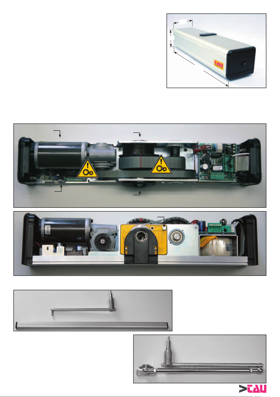
1.0 COMPONENTI AUTOMAZIONE
1- Dip e potenziometri di regolazione 5- Alloggiamento scheda tastiera
2- Scheda alimentazione e connessioni 6- Alloggiamento scheda fotocellula
3- Molla 7- Perno d’uscita
4- Riferimento di precarica molla 8- Vite di blocco molla
5
7
3
1
4
550
2
6
2.0 BRACCETTI
7
8
BRACCIO A SLITT A A TIRARE
BRACCIO ARTICOLA TO A SPINT A
4
BRINK Series - Italiano
Page 5

3.0 AVVERTENZE GENERALI PER LA SICUREZZA
Iniziare l’installazione solo dopo l’attenta lettura di questo manuale di istruzioni.
Sia la parte meccanica che quella elettrica devono essere installate attenendosi alle regole della Buona Tecnica e alle norme vigenti.
L’inosservanza di queste può essere fonte di pericolo per persone o cose.
L’installatore del prodotto deve essere persona competente e professionalmente preparata il quale deve verifi care che la struttura da
automatizzare sia stabile e robusta e se necessario renderla tale mediante modifi che strutturali. Deve inoltre controllare che tutte le
zone in cui vi è pericolo di: schiacciamento , convogliamento , cesoiamento e pericoli in genere siano protette per mezzo di dispositivi
elettronici di sicurezza, franchi di sicurezza o barriere di sicurezza. Questi dispositivi devono essere installati secondo le norme in vigore
e secondo le regole della Buona Tecnica tenendo in considerazione anche l’ambiente di utilizzo, la tipologia di utilizzazione e la logica
di funzionamento del prodotto. Le forze sviluppate del sistema completo durante il funzionamento devono sottostare alle norme vigenti,
e dove questo non fosse possibile, proteggere per mezzo di dispositivi elettronici di sicurezza le zone interessate dalle forze stesse. Le
zone pericolose devono essere segnalate secondo quanto prevedono le normative vigenti.
Prima di collegare il prodotto accertarsi che la rete di distribuzione elettrica abbia caratteristiche compatibili con quelle descritte nei dati
tecnici di questo manuale e che a monte dell’impianto vi siano un interruttore differenziale e una protezione di sovracorrenti adeguati.
Ricordarsi di togliere alimentazione prima di effettuare ogni intervento sull’automazione sia di manutenzione che di installazione ed in
ogni caso prima di aprire la copertura.
Le cariche elettrostatiche possono danneggiare i componenti elettronici presenti sulle schede; utilizzare bracciali antistatici collegati a
terra nel caso si debba operare sulle schede elettroniche. Non mettere le mani od altre parti del corpo nei componenti in movimento come
cinghie, pulegge , ingranaggi ecc..
La manutenzione del prodotto è di fondamentale importanza per il buon funzionamento e per la sicurezza dell’impianto; essa deve
seguire le direttive del costruttore descritte in questo manuale.
Il costruttore declina ogni responsabilità per una installazione ed un uso improprio del prodotto o per danni derivanti da modifi che
all’impianto apportate di propria iniziativa. Per la sostituzione e la riparazione di componenti del prodotto dovranno essere utilizzati
esclusivamente ricambi originali. Il costruttore non è responsabile della costruzione degli infi ssi da automatizzare né degli eventuali danni
causati dall’inosservanza della Buona Tecnica nella costruzione degli infi ssi stessi.
Il grado di protezione Ip22 prevede l’installazione dell’ automatismo solo nel lato interno degli edifi ci. Il costruttore declina ogni
responsabilità da eventuali danni causati da montaggio esterno senza adeguate misure di protezione.
Prima di installare il prodotto verifi carne sempre l’integrità.
Questo prodotto non può essere installato in ambiente ed atmosfera esplosivi od in presenza di gas o fumi infi ammabili.
Al termine della sua vita questo prodotto dovrà essere smaltito secondo le vigenti norme.
Non lasciare materiali derivanti dal prodotto o dall’imballaggio dello stesso alla portata dei bambini in quanto potrebbero creare fonti di
pericolo.
PARTE MECCANICA
4.0 DIRETTIVA MACCHINE
Le chiusure pedonali automatizzate come stabilito dalla commissione della UE rientrano nel campo di applicazione delle direttive
macchine (98/37/CE). Quest’ultima stabilisce che l’installatore che motorizza una porta o un cancello ha gli stessi obblighi del costruttore
della macchina:
1. Predisporre il fascicolo tecnico (completo di documenti come descritto nell’allegato V della Direttiva Macchine).
2. Redigere la relativa conformità CE (secondo l’allegato II-A della Direttiva Macchine).
3. Apporre sulla porta motorizzata la marcatura CE (1.7.3, dell’allegato I della Direttiva Macchine).
L’installatore deve conservare il fascicolo tecnico e tenerlo a disposizione delle autorità nazionali competenti per almeno 10 anni a
decorrere dalla data di costruzione della porta motorizzata.
L’installatore deve consegnare al cliente i seguenti documenti:
1. L’istruzione di funzionamento e di uso sicuro dell’impianto.
2. Le istruzioni di manutenzione ordinaria.
3. La dichiarazione di conformità.
4. Il registro di manutenzione.
5.0 INDICAZIONI DI UTILIZZO
L’automazione BRINK-S è adatta per l’utilizzo di tipo continuo. Il peso massimo dell’anta utilizzabile è in relazione con l’anta stessa, al
tipo di braccetto utilizzato.
Vedere le tabelle al capitolo 7 a seconda dell’ applicazione utilizzata.
Le caratteristiche sopra descritte si riferiscono ad una installazione tipo e possono essere infl uenzate in maniera sostanziale dalle
variabili presenti in ogni installazione, quali: attriti, bilanciature, condizioni ambientali ecc.
6.0 PREPARAZIONE E FISSAGGIO DELL’AUTOMAZIONE
Prima di procedere con il fi ssaggio dell’automazione e dei braccetti verifi care che la struttura di sostegno dell’automazione sia robusta
ed affi dabile, che l’anta da movimentare abbia adeguati cardini, che l’anta stessa non presenti attriti che potrebbero infl uenzare il buon
funzionamento del sistema e che i punti di fi ssaggio del braccetto sull’ anta siano adeguatamente robusti.
Nel caso uno di questi punti fosse critico rinforzarlo con elementi adeguati (piastre aggiuntive, cardini più robusti ecc.)
La porta necessita di un arresto a pavimento in posizione aperta per evitare che una violenta apertura manuale ne danneggi i meccanismi.
L’arresto a pavimento non è fornito con l’automazione e deve quindi essere procurato dall’installatore.
BRINK Series - Italiano
5
Page 6
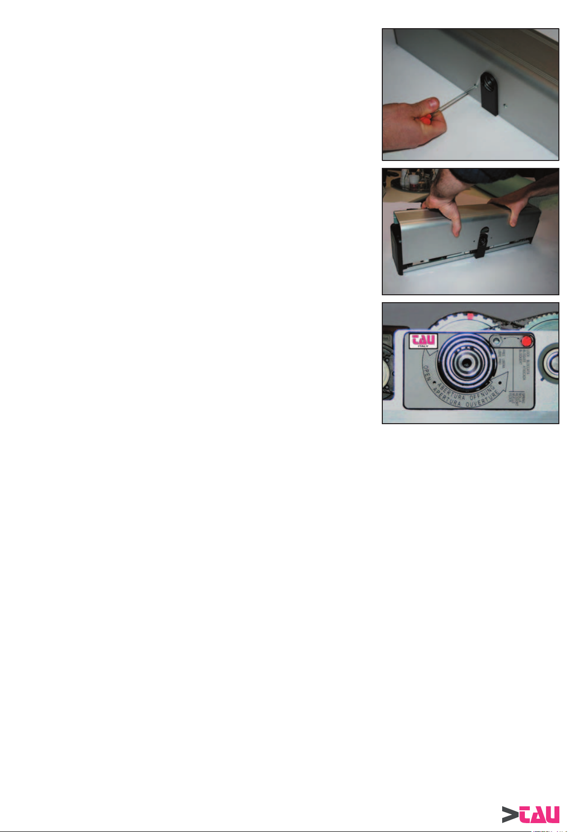
Togliere dall’imballo l’automazione e verifi carne l’integrità.
Rimuovere le viti di tenuta del coperchio.
PARTE MECCANICA
Sfi lare il coperchio in alluminio dalla sua sede tirando forte verso l’alto e possibilmente
senza far pressione sui lati.
L’automazione prevede la possibilità di connettere il braccetto in entrambi i lati del corpo
meccanico e quindi permette di selezionare la direzione del movimento di apertura.
Identifi care il lato di connessione del braccetto per mezzo dell’etichetta presente sul
corpo meccanico. Questa indica la direzione di apertura del perno. Tenere presente
che tipo di braccetto (a slitta o articolato) e che tipo di fi ssaggio (su muro o su anta) si
andranno ad utilizzare.
Sull’ automazione sono presenti due tappi di chiusura per le uscite del perno di cui uno
sfondato per il passaggio dello stesso e uno integro; scambiarli nel caso la connessione
del braccetto utilizzi l’uscita albero con il tappo integro.
Nelle seguenti pagine sono indicati i modi di utilizzo dell’automazione sia con braccio articolato a spinta che con braccio a slitta a tirare.
Attenersi alle fi gure per quel che riguarda le distanze ed i fori da effettuare oppure utilizzare le dime di foratura in scala 1:1 presenti in
ogni confezione di braccetti.
6
BRINK Series - Italiano
Page 7
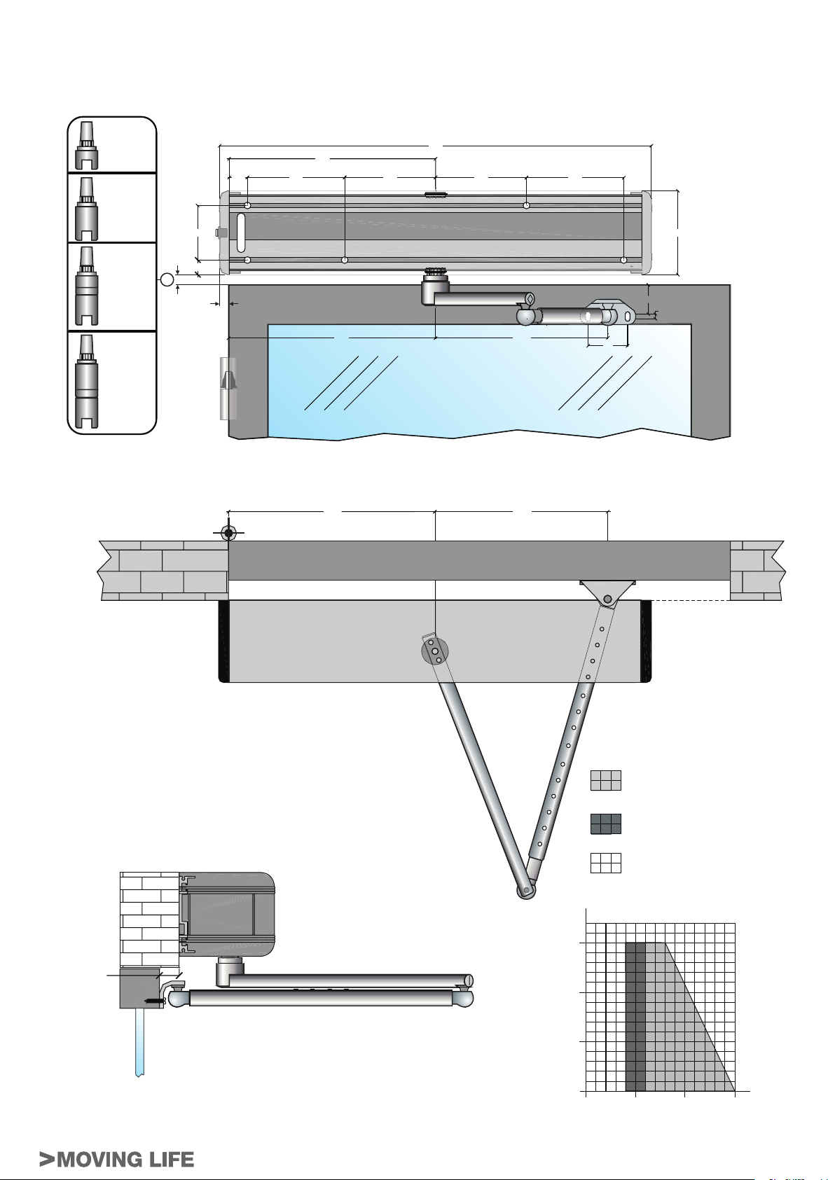
7.0 DISEGNI TECNICI
STANDARD
!
8 MM
"
8 MM
!#
8 MM
8
"2!##)/ !24)#/,!4/ ! 30).4!
PARTE MECCANICA
"#
8 MM
MM
BRINK Series - Italiano
,UNGHEZZA E PESO ANTA
UTILIZZABILI
+G
,UNGHEZZA E PESO ANTA UTILIZZABILI
CON DIVERSE DIMENSIONI DI FISSAGGIO
,UNGHEZZA E PESO ANTA
./. UTILIZZABILI
$ISEGNI DI FISSAGGIO FORNIBILI A RICHIESTA
MM
7
Page 8

"2!##)/ ! 3,)44! ! 4)2!2%
STANDARD
!
8 MM
PARTE MECCANICA
"
8 MM
!#
8 MM
"#
8
MM
MM
8
,UNGHEZZA E PESO ANTA
UTILIZZABILI
,UNGHEZZA E PESO ANTA UTILIZZABILI
CON DIVERSE DIMENSIONI DI FISSAGGIO
,UNGHEZZA E PESO ANTA
./. UTILIZZABILI
+G
$ISEGNI DI FISSAGGIO FORNIBILI A RICHIESTA
MM
8
BRINK Series - Italiano
Page 9
8.0 CONNESSIONE DEI BRACCETTI
Attenzione seguire scrupolosamente i passi qui descritti per il fi ssaggio dei braccetti, in particolare rimuovere la vite di blocco precarica
molla solo quando specifi cato nelle istruzioni. La rimozione della vite di blocco precarica molla causa il movimento delle pulegge e degli
ingranaggi presenti nell’automazione. Allontanare dita o parti del corpo nei pressi degli organi di movimento durante questa operazione!
Effettuare questa operazione solo dopo aver tolto la tensione di alimentazione all’automazione.
Dopo aver fi ssato l’automazione e il braccetto seguendo gli schemi delle pagine precedenti ( o utilizzando la dima di foratura in scala 1:1
presente in ogni confezione di braccetto), eseguire il collegamento del braccetto all’ albero di uscita dell’ automazione come descritto nei
seguenti passi:
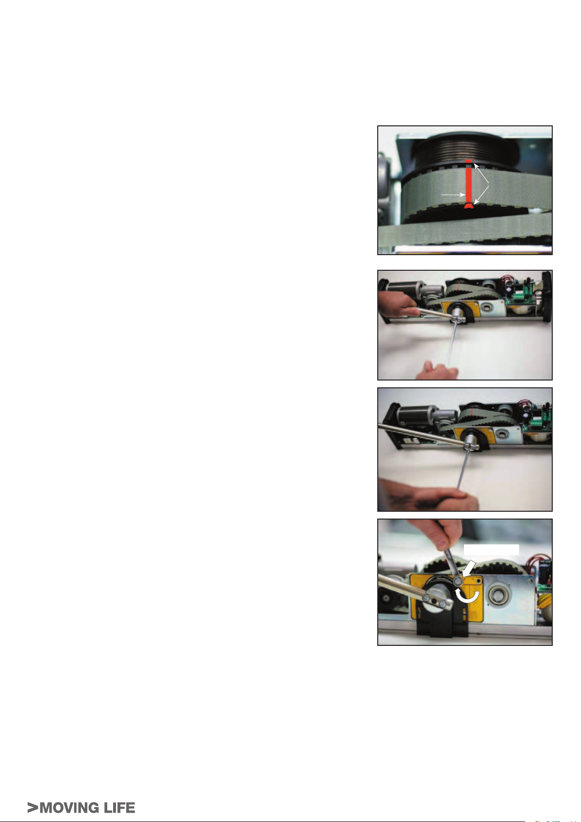
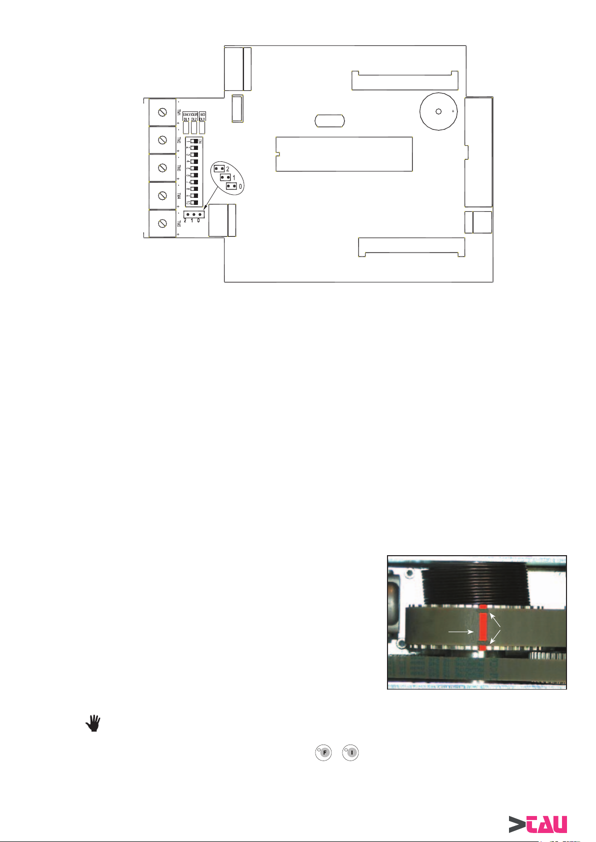
8.1 Scelta del carico della molla
La molla di chiusura è precaricata in fabbrica ad un valore standard segnalato dalla
coincidenza del segno rosso sulla cinghia con il segno rosso presente nella puleggia
(vedere fi gura a lato). Controllare che questa condizione sia presente nel prodotto
installato, se così non fosse seguire quanto descritto nel capitolo 3) a pagina
riportare la precarica al valore standard.
Nonostante la precarica sia fi ssa è possibile scegliere la potenza della molla in chiusura
seguendo questa semplice regola:
Collegare il braccetto all’ albero di uscita con l’anta completamente aperta per avere la
molla caricata al minimo.
Collegare il braccetto all’ albero di uscita con l’anta completamente chiusa per avere la
molla caricata al massimo.
La connessione in una posizione intermedia carica la molla ad un valore
proporzionalmente intermedio.
8.2 Fissaggio terminale conico del braccetto
Accertarsi che il tappo copriforo sia inserito sul telaio.
Connettere il terminale conico del braccetto nel perno di uscita.
Nel terminale del braccetto è presente una calettatura che impedisce al braccetto di
slittare anche con la vite non propriamente serrata.
Controllare che la calettatura del terminale si accoppi con quella presente nel perno
d’uscita.
Se nella posizione di inserimento scelta non è possibile l’accoppiamento, ruotare il
terminale del braccetto fi no a trovare un punto di inserimento corretto (uno ogni 45°).
18 per
RIFERIMENTO
CINGHIA
RIFERIMENTI
PULEGGIA
PARTE MECCANICA
Serrare forte la vite di fi ssaggio del braccetto.
Ricordarsi di ricontrollare il serraggio della vite a fi ne installazione e dopo che la
porta abbia effettuato alcune aperture e chiusure per mezzo del motore.
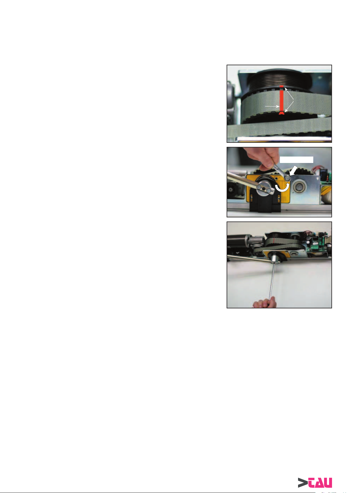
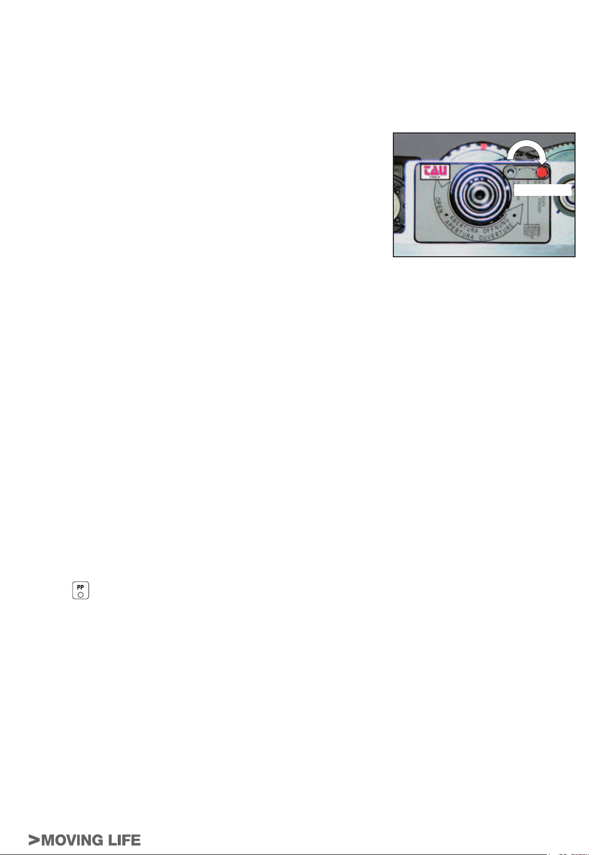
8.3 Sblocco della molla
Attenzione:
Durante questa operazione gli organi di movimento e il braccetto della porta si possono
mettere in movimento; allontanare dita o parti del corpo nei pressi degli organi di
movimento durante questa operazione o mantenere l’anta bloccata manualmente.
Spostare la vite di blocco molla dalla posizione bloccata a quella libera come descritto in
fi gura a lato. La porta è ora libera di chiudere per mezzo della molla. Assicurarsi che la
porta chiuda completamente anche con pochi gradi di apertura, in caso contrario ripetere
le operazioni di questo capitolo incrementando la forza di chiusura come descritto nel
paragrafo 8.1Per disconnettere il braccetto seguire le istruzioni del capitolo seguente.
LIBERA
BRINK Series - Italiano
9
Page 10
9.0 RIMOZIONE DEI BRACCETTI
Attenzione:
Seguire scrupolosamente i passi qui descritti per la rimozione dei braccetti, in particolare rimuovere la vite di fi ssaggio del perno conico
e avvitare il dado di estrazione solo quando specifi cato nelle istruzioni. La rimozione della vite di fi ssaggio del perno conico e l’utilizzo
del dado di estrazione possono causare il movimento delle pulegge e degli ingranaggi presenti nell’automazione se la molla di chiusura
non è stata precedentemente bloccata.
Allontanare dita o parti del corpo nei pressi degli organi di movimento durante questa operazione!
PARTE MECCANICA
9.1 Riposizionamento sulla precarica standard e blocco della molla
Prima di togliere il braccetto è necessario riportare la carica della molla sul valore
standard segnalato dalla coincidenza del segno rosso sulla cinghia con il segno rosso
presente sulla puleggia (vedere fi gura a lato) e bloccare la molla in questa posizione.
Per fare ciò muovere manualmente la porta fi no a che non si soddisfa questa condizione
di coincidenza delle linee rosse cinghia-puleggia.
Spostare la vite di bloccaggio dalla posizione libera alla posizione bloccata facendo
attenzione che la vite si inserisca nel foro di blocco presente nella puleggia.
RIFERIMENTO
CINGHIA
RIFERIMENTI
PULEGGIA
BLOCCATA
9.2 Estrazione del perno conico
Togliere la vite di fi ssaggio del perno conico.
10
BRINK Series - Italiano
Page 11
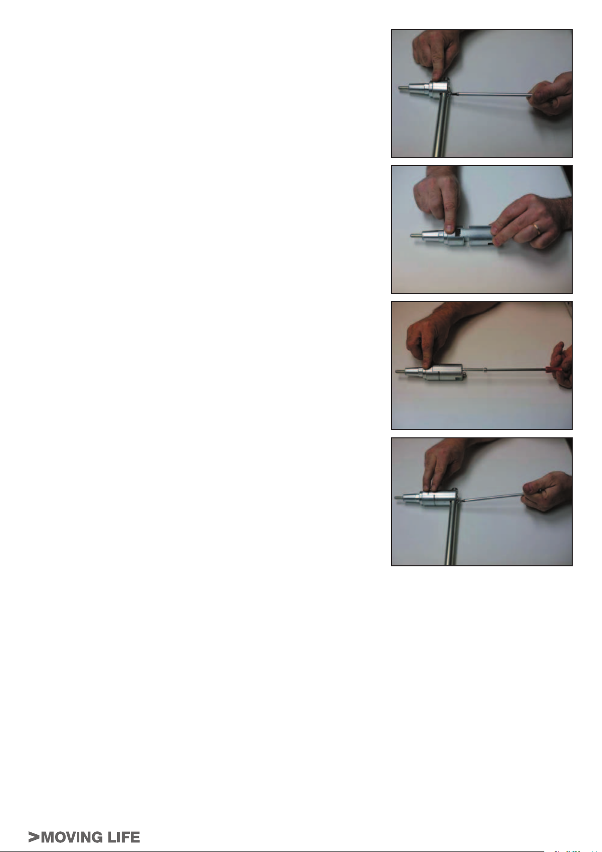
10.0 PROLUNGA PERNO DI USCITA
Per applicazioni dove l’altezza standard della connessione conica del braccetto dovesse
risultare insuffi ciente è disponibile una estensione (opzionale) per incrementare l’altezza
dello stesso.
Per le altezze disponibili riferirsi al paragrafo 7.0 (dime di fi ssaggio)
Per prima cosa scollegare il braccetto dalla sua connessione conica svitando le due viti
di testa.
Accoppiare l’estensione con la connessione conica come in fi gura.
Ricordarsi di mantenere la vite di fi ssaggio all’interno.
Fissare l’estensione alla connessione conica per mezzo delle viti in dotazione all’
estensione stessa.
PARTE MECCANICA
Riposizionare il braccetto sull’estensione e fi ssarlo con le stesse viti che lo fi ssavano
sulla connessione conica.
Per il collegamento e lo sblocco del braccetto completo all’operatore riferirsi ai paragrafi precedenti.
BRINK Series - Italiano
11
Page 12
BRINK (con chiusura a motore)
BRINK-S (con chiusura a molla)
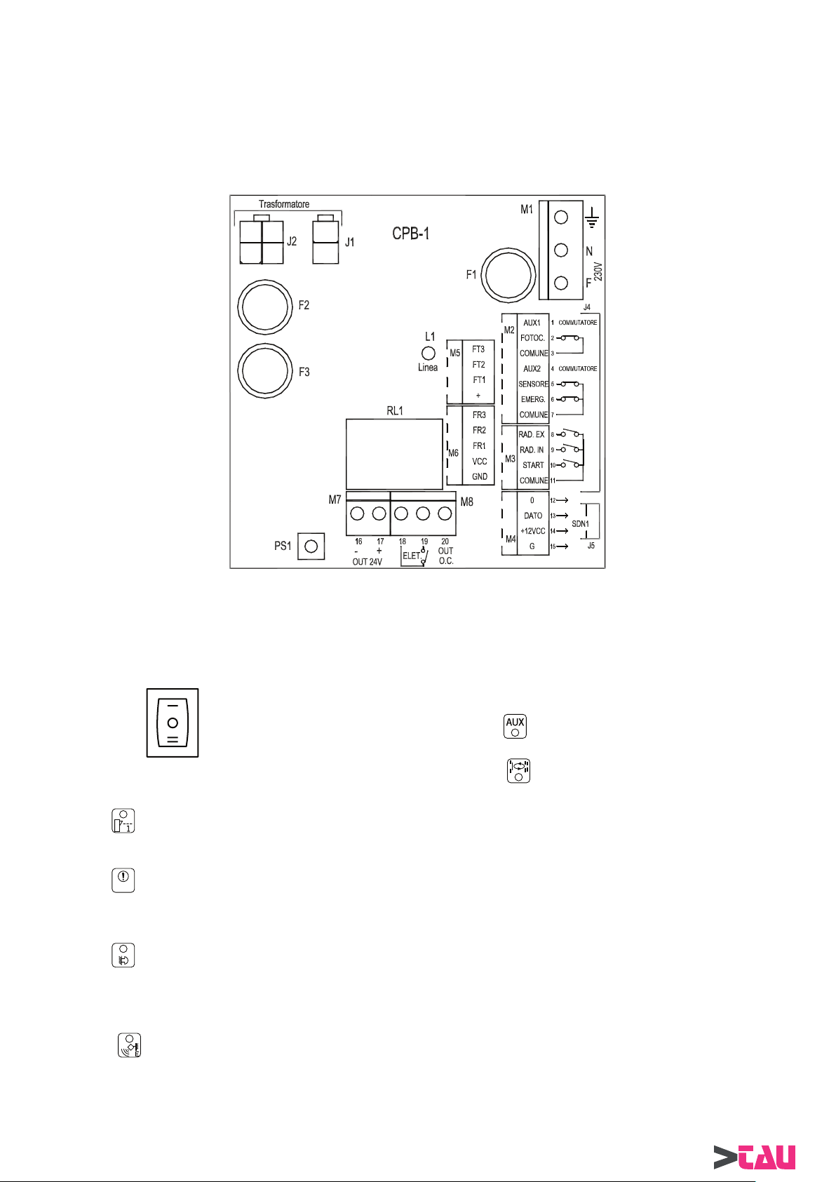
1) COLLEGAMENTI ELETTRICI
PARTE ELETTRONICA
Fig. 1
● MORSETTIERA M1
Alimentazione 230V a.c.: fase al morsetto F, neutro al morsetto N + connessione di terra.
La linea è protetta dal fusibile F1 da 5A.
● MORSETTIERA M2
Morsetti 1-3-4 = collegamento del commutatore di SCELTA FUNZIONI collocato sul fi anco laterale dall’automatismo.
contatto centrale sul morsetto comune 3;
contatto chiuso sulla posizione | al morsetto AUX1 ;
contatto chiuso sulla posizione || al morsetto AUX2 ;
Morsetti 2-3
Morsetti 5-7 = ingresso N.C. del SENSORE di sicurezza in apertura mod. DOORSS340.
Morsetti 6-7 = ingresso N.C. di EMERGENZA. Apre la porta in ogni condizione.
= ingresso N.C. di FOTOCELLULA di sicurezza.
Interviene in chiusura, invertendo il senso di marcia.
La rilevazione di un ostacolo o di una presenza causa l’arresto della porta, con una ripresa del moto in
apertura solo a sensore liberato.
Può funzionare anche in modo passo-passo (vedi paragrafo 7).
● MORSETTIERA M3
Morsetti 8-11 = ingresso N.A. di RADAR ESTERNO. Comanda l’apertura della porta.
Viene escluso dal selettore digitale DOORPROGB nelle funzioni blocco notte o solo uscita.
Viene escluso dal selettore manuale DOORSELFB nelle funzioni blocco notte o solo uscita.
Può funzionare anche come ingresso di sola apertura (vedi par.7).
12
BRINK Series - Italiano
Page 13

Morsetti 9-11 = ingresso N.A. di RADAR INTERNO. Comanda l’apertura della porta.
Viene escluso dal selettore digitale DOORPROGB nelle funzioni blocco notte o solo entrata.
Viene escluso dal selettore manuale DOORSELFB nella funzione blocco notte.
Può funzionare anche come ingresso di sola chiusura (vedi par.7).
Morsetti 10-11
● MORSETTIERA M4
Collegamento al selettore digitale DOORPROGB. Utilizzare un cavo a 4 poli (diametro 0,5mm.) mantenendo la stessa corrispondenza
dei segnali tra selettore e centralina. Lunghezza massima del cavo 20 metri.
Al fi ne di evitare false visualizzazioni sul selettore, mantenere il cavo di collegamento lontano da fonti di disturbo elettrico.
Morsetto 12 = 0 (negativo di alimentazione)
Morsetto 13 = DATO
Morsetto 14 = +12Vcc (positivo di alimentazione)
Morsetto 15 = G (terra)
Utilizzare la morsettiera a 4 poli presente nel kit del selettore DOORPROGB.
ATTENZIONE!
Nel kit del selettore DOORPROGB è presente la scheda di interfaccia “LOGIC TAST”, che deve essere inserita nel connettore
J8 (vedi fi g. 2) per ottenere il funzionamento del selettore con la centralina BRINK.
● MORSETTIERE M5 - M6 = Dedicate al collegamento delle capsule fotocellule DOORFOTO2; consultare il paragrafo 12 per il
● MORSETTIERA M7
Morsetti 16 (-)-17(+) = uscita 24Vdc, max. 20W, per alimentazione accessori esterni.
= ingresso N.A. di START. Comanda l’apertura della porta e avvia il settaggio iniziale.
Viene escluso dal selettore digitale DOORPROGB nella funzione blocco notte.
Viene escluso dal selettore manuale DOORSELFB nella funzione blocco notte.
Può funzionare anche in modo passo-passo (vedi par.7).
modo di funzionamento.
La linea è protetta dal fusibile F2 da 4A.
Il led L1 indica la presenza della linea di alimentazione.
PARTE ELETTRONICA
● MORSETTIERA M8
Morsetti 18-19 = contatto pulito N.A. del relè RL1 utilizzabile per il collegamento di un’elettroserratura.
Prelevare l’alimentazione dai morsetti 16-17 nel caso di elettroserrature a 24V.
Morsetto 20 = uscita segnale di tipo OPEN COLLECTOR, attiva con porta aperta o in movimento: portata max
100mA.
Prelevare il segnale positivo dal morsetto 17.
CONNETTORI J1-J2 = collegamento del trasformatore di alimentazione: primario su J1, secondario su J2.
CONNETTORI J4-J10 = cablaggio dei conduttori di segnale tra la parte dei collegamenti elettrici CPB-1 e la parte logica LGN
della centralina elettronica.
CONNETTORI J5-J11 = cablaggio dei conduttori di alimentazione tra le parti CPB-1 e LGN della centrale.
La linea è protetta dal fusibile F3 da 8A.
CONNETTORE J6 = collegamento encoder.
CONNETTORE J7 = collegamento motore
BRINK Series - Italiano
13
Page 14
2) DESCRIZIONE DELLA PARTE LOGICA LGN DELLA CENTRALINA
PARTE ELETTRONICA
VELOCITÀ
APERTURA
VELOCITÀ
CHIUSURA
DISTANZA
SENSORE
POTENZA
PAUSA
J12
DIP SWITCH
S1
MOTOR
J7
J6
ENCODER
J13
MP1
NEPTIS
X1
LGN
MODULO SELETT. DOORPROGB
LOGIC TAST
J8
BUZZER
J10
J9
PHOTOCELL CONTROL
J11
Fig. 2
DL1 - DL2 = visualizzano i segnali provenienti dal sensore dell’encoder.
DL3 = visualizza il corretto funzionamento del microprocessore MP1 lampeggiando molto velocemente; il
led spento o lampeggiante lentamente indica una anomalia sulla scheda logica.
CONNETTORE J8 = innesto per il modulo interfaccia LOGIC TAST del selettore DOORPROGB.
CONNETTORE J9 = innesto per la scheda fotocellule DOORFOTO1.
CONNETTORE J13 = collegamento tra la centralina MASTER e la centralina SLAVE nel caso di porta battente a due ante
(vedi paragrafo 13). Utilizzare il cablaggio MASTER/SLAVE per BRINK mod.WR3MS.
JUMPER J12 = seleziona la velocità di richiusura della porta in assenza di tensione di alimentazione di rete:
Solo per la
versione
BRINK-S
con Jumper nello stato 0 = velocità bassa;
con Jumper nello stato 1 = velocità intermedia;
con Jumper nello stato 2 = velocità alta.
Dip switch S1 = seleziona i programmi di lavoro della centralina (vedi par. 6).
Potenziometri = taratura dei parametri di lavoro (vedi par. 8).
Buzzer = avvisatore acustico.
MP1 = microprocessore con etichetta indicante la versione software.
3) COME REIMPOSTARE LA PRECARICA MOLLA
Leggere questo paragrafo solo se durante l’installazione viene inavvertitamente scollegato il braccetto senza riportare la molla in posizione
standard e ribloccata. In questo caso la molla si scaricherebbe ben oltre il suo livello preimpostato.
L’automatismo BRINK-S viene fornito con la molla di richiusura precaricata su un valore
standard segnalato dalla coincidenza del segno rosso sulla cinghia con il segno rosso
presente sulla puleggia (vedere fi gura a lato).
Se, durante l’installazione, viene inavvertitamente scollegato il braccetto senza prima
riportare e bloccare in posizione standard la molla con la vite di blocco, la molla si
scarica ben oltre il suo valore standard .
Per riportare quest’ ultima nella posizione corretta seguire scrupolosamente i seguenti
passi:
a) Scollegare completamente il braccetto dal perno di uscita se questo fosse ancora
inserito.
b) Assicurarsi che il commutatore di SCELTA FUNZIONI sul fi anco laterale del-
l’operatore si trovi nella posizione centrale “0”.
RIFERIMENTO
CINGHIA
RIFERIMENTI
PULEGGIA
Se è installato il selettore meccanico DOORSELFB posizionare la manopola in posizione
di porta libera
Se è installato il selettore digitale DOORPROGB assicurarsi che le spie
.
e siano spente.
c) Regolare a circa metà corsa il potenziometro TM4 di limitazione potenza e alimentare la centralina.
d) Posizionare in OFF il dip 6 del Minidip S1
e) Togliere alimentazione di rete (230V) per circa 5 secondi
14
BRINK Series - Italiano
Page 15
f) Collegare alimentazione di rete ed attendere un segnale acustico (“BIP”)
g) Posizionare in ON il dip 6 del Minidip S1
h) Togliere alimentazione di rete (230V) per circa 5 secondi
i) Collegare alimentazione di rete ed attendere un segnale acustico (“BIP”)
j) Posizionare in OFF il dip 6 del Minidip S1
k) Togliere alimentazione di rete (230V) per circa 5 secondi
l) Collegare alimentazione di rete ed attendere un segnale acustico (“BIP”)
m) Premere il pulsante PS1 (START) sulla scheda CPB-1, la centralina emette 5 bip e avvia la manovra di caricamento molla in
funzionamento presenza uomo (al rilascio dello start il moto si arresta, per riprendere al successivo azionamento dello start).
n) Riportare la carica della molla sul valore standard segnalato dalla coincidenza del
segno rosso sulla cinghia con il segno rosso presente sulla puleggia (vedere fi gura
a lato) e bloccare la molla in questa posizione.
o) Spostare la vite di bloccaggio dalla posizione libera alla posizione bloccata facendo
attenzione che la vite si inserisca nel foro di blocco presente nella puleggia.
p) !! ATTENZIONE, dopo queste operazioni il SETTAGGIO INIZIALE viene
cancellato e dovrà perciò essere eseguito al momento opportuno seguendo
la procedura descritta al paragrafo 4.
BLOCCATA
4) MESSA IN FUNZIONE DELL’AUTOMATISMO (SETTAGGIO INIZIALE)
Nota: prima di eseguire il SETTAGGIO INIZIALE, impostare il dip 5 in base al tipo di funzionamento (vedi par. 6).
Dopo aver fi ssato l’automatismo alla porta ed effettuato il caricamento della molla (solo per la versione BRINK-S), spostare l’anta a mano
per l’intera corsa verifi cando che il movimento sia fl uido, privo di attriti e che termini con la porta in appoggio ad una battuta fi nale.
Procedere alla fase di inizializzazione (settaggio iniziale), operazione obbligatoria per consentire alla centralina di acquisire i fi necorsa;
seguire scrupolosamente i seguenti passi:
a) Assicurarsi che l’automazione non sia alimentata e che i dip switch di S1 siano nello stato OFF.
b) Posizionare il dip-switch 6 di S1 in ON e il commutatore di SCELTA FUNZIONI su “|” (funzioni giorno).
c) Posizionare il dip-switch 4 di S1 in ON solo se è presente l’elettroserratura.
d) Posizionare il dip switch 5 di S1 in ON se, nella versione BRINK-S, si vuole abilitare la chiusura con la spinta del motore in
aggiuntaa quella della molla.
e) Posizionare la porta nello stato di chiusura.
f) Alimentare l’automatismo: la centralina emetterà 3 bip, di cui gli ultimi due molto ravvicinati tra di loro.
PARTE ELETTRONICA
ATTENZIONE!
Durante il settaggio iniziale la porta si muove con una potenza di spinta superiore rispetto alle condizioni normali di lavoro, per
cui è consigliabile procedere con cautela evitando di occupare lo spazio di apertura.
g) Premere il pulsante PS1 (ingresso start) sulla scheda CPB-1.
h) versione BRINK-S: la porta effettuerà un ciclo completo di apertura a velocità lenta.
Al termine della manovra un BIP prolungato segnala la fi ne della procedura.
La chiusura avviene al termine del tempo di pausa.
versione BRINK: la porta spingerà leggermente in chiusura, quindi effettuerà un ciclo completo di apertura / chiusura a velocità
lenta.
Al termine della chiusura un BIP prolungato segnala la fi ne della procedura.
IMPORT ANTE: durante la fase di inizializzazione, non dovranno essere presenti ostacoli nello spazio di manovra e la porta non
deve essere aiutata manualmente.
Al termine del settaggio iniziale avviare una manovra di apertura tramite un ingresso di comando e verifi care la movimentazione secondo
le regolazioni di default.
SICUREZZA: In fase di spunto e a tratti durante il movimento è possibile verifi care, tramite l’ascolto del buzzer e la visualizzazione
sulla spia
movimento che determini un arresto con successiva inversione del senso di marcia.
Mediante il potenziometro TM4 sulla scheda LGN è possibile variare la potenza di spinta della porta, tarando con precisione la soglia di
intervento desiderata.
Una breve segnalazione del buzzer solo durante lo spunto indica una buona taratura della potenza di spinta.
Per escludere l’ascolto tramite buzzer della limitazione di potenza posizionare il dip 6 di S1 nello stato OFF.
Dopo 5 tentativi di chiusura consecutivi della porta in cui un ostacolo dovesse causare continuamente l’inversione in apertura, il tempo
di pausa a porta aperta verrà automaticamente incrementato a 20 secondi, fi no a quando l’ostacolo non sarà rimosso e la porta riuscirà
a completare la fase di chiusura.
Infi ne, provvedere a selezionare le funzioni desiderate, impostare velocità, tempi e distanze per ottimizzare il funzionamento della porta
secondo le proprie esigenze.
del selettore DOORPROGB, la forza di spinta della porta e constatarne l’effettiva intensità opponendo un ostacolo al
4.1) CANCELLAZIONE DI UN PRECEDENTE SETTAGGIO INIZIALE
Nel caso di una variazione della corsa dell’anta, del peso della porta o del caricamento della molla (solo per la versione BRINK-S),
l’operazione di inizializzazione della centralina deve essere ripetuta.
Agire nel seguente modo:
1. Togliere alimentazione, posizionare il dip switch 6 di S1 nello stato OFF e alimentare la centralina;
2. Dopo il bip iniziale, posizionare il dip switch 6 di S1 nello stato ON e togliere alimentazione;
3. Alimentare la centralina, attendere il bip iniziale e riportare il dip switch 6 di S1 nello stato OFF;
4. Togliere alimentazione;
5. Il precedente settaggio iniziale è stato cancellato;
6. Per eseguire nuovamente il settaggio iniziale ripetere le operazioni dal precedente punto a) al punto h).
BRINK Series - Italiano
15
Page 16
5) DISPOSITIVI MANUALI DI SCELTA FUNZIONE
5.1) COMMUTATORE DI SCELTA FUNZIONI
Tramite il commutatore di SCELTA FUNZIONI collocato sul fi anco laterale dell’automatismo è possibile
selezionare il programma di lavoro della porta.
Stato “|” = FUNZIONI GIORNO.
Sono attivi tutti gli ingressi di comando.
PARTE ELETTRONICA
5.2) SELETTORE MECCANICO DOORSELFB
Il selettore meccanico DOORSELFB permette di impostare il programma di lavoro dell’operatore BRINK.
ATTENZIONE!
Utilizzando il selettore meccanico DOORSELFB, mantenere nello stato “0” il commutatore di scelta funzioni sul fi anco laterale
dell’automatismo e posizionare il dip 7 di S1 nello stato OFF; questo per evitare confl itto tra le funzioni impostate nel selettore
meccanico DOORSELFB e le funzioni impostate sul commutatore incorporato sull’operatore stesso.
Se esistesse il rischio di un azionamento indesiderato del commutatore di scelta funzioni, si consiglia di scollegarlo dalla
morsettiera della centralina BRINK.
Stato “O” = PORTA LIBERA.
Il motore non viene alimentato ed è possibile muovere la porta manualmente.
Stato “||” = BLOCCO NOTTE (con dip 7 di S1 in OFF).
La porta può essere aperta solo con l’ingresso di EMERGENZA.
PORTA APERTA (con dip 7 di S1 in ON).
Condizione di porta aperta.
5.2.1) COLLEGAMENTI ELETTRICI
MORSETTO 1 = collegare all’ingresso 9 (RADAR INTERNO) della CPB-1 della centralina BRINK;
MORSETTO 2 = collegare all’ingresso 3 (COMUNE) della CPB-1 della centralina BRINK;
MORSETTO 3 = collegare all’ingresso 1 (AUX1) della CPB-1 della centralina BRINK;
MORSETTO 4 = collegare all’ingresso 4 (AUX2) della CPB-1 della centralina BRINK;
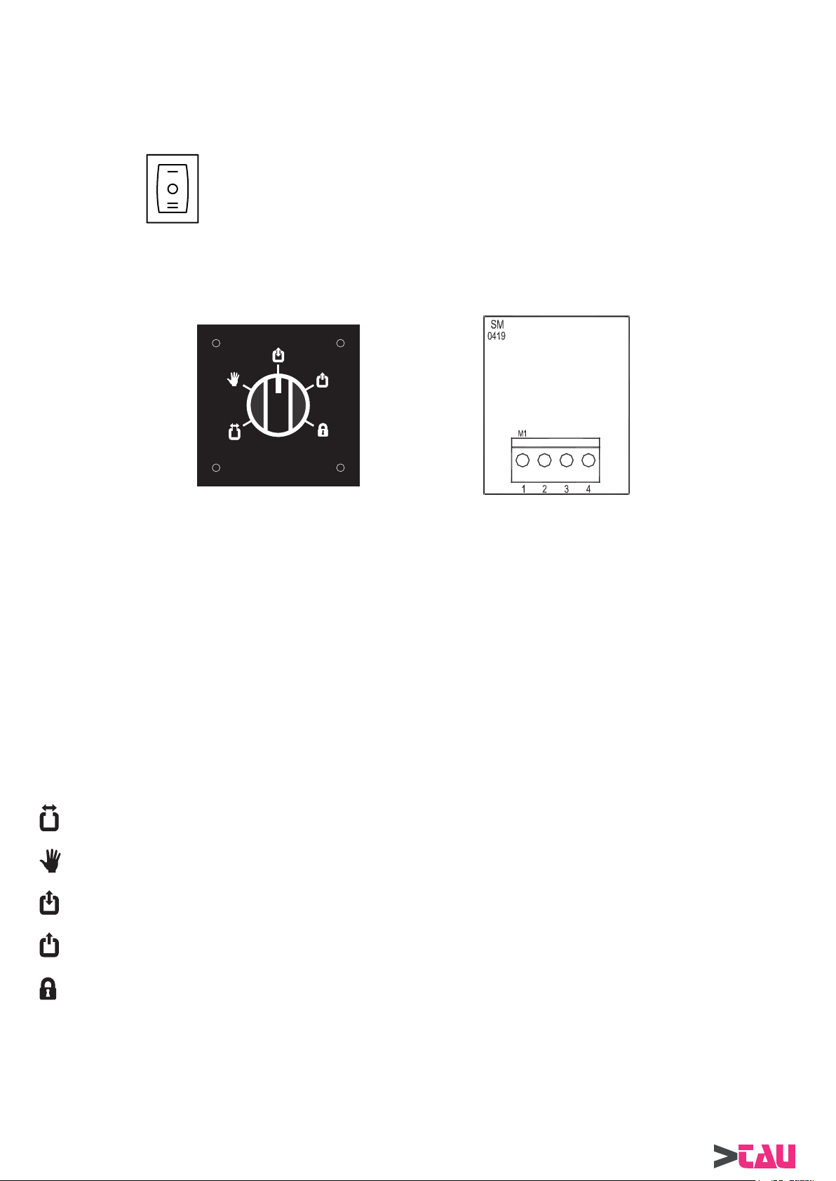
5.2.2) MODALITA’ DI FUNZIONAMENTO
Ruotare la manopola del selettore meccanico DOORSELFB per selezionare la funzione desiderata tra le 5 disponibili:
PORTA SEMPRE APERTA = per mantenere la porta completamente aperta.
PORTA LIBERA = per muovere la porta manualmente senza il controllo del motore.
TRAFFICO NEI DUE SENSI = per aprire la porta tramite tutti gli ingressi di comando.
TRAFFICO SOLO IN USCITA = per escludere la rilevazione dell’ingresso RADAR ESTERNO.
BLOCCO NOTTE = per mantenere la porta chiusa, consentendo l’apertura solo con l’ingresso di EMERGENZA.
16
BRINK Series - Italiano
Page 17
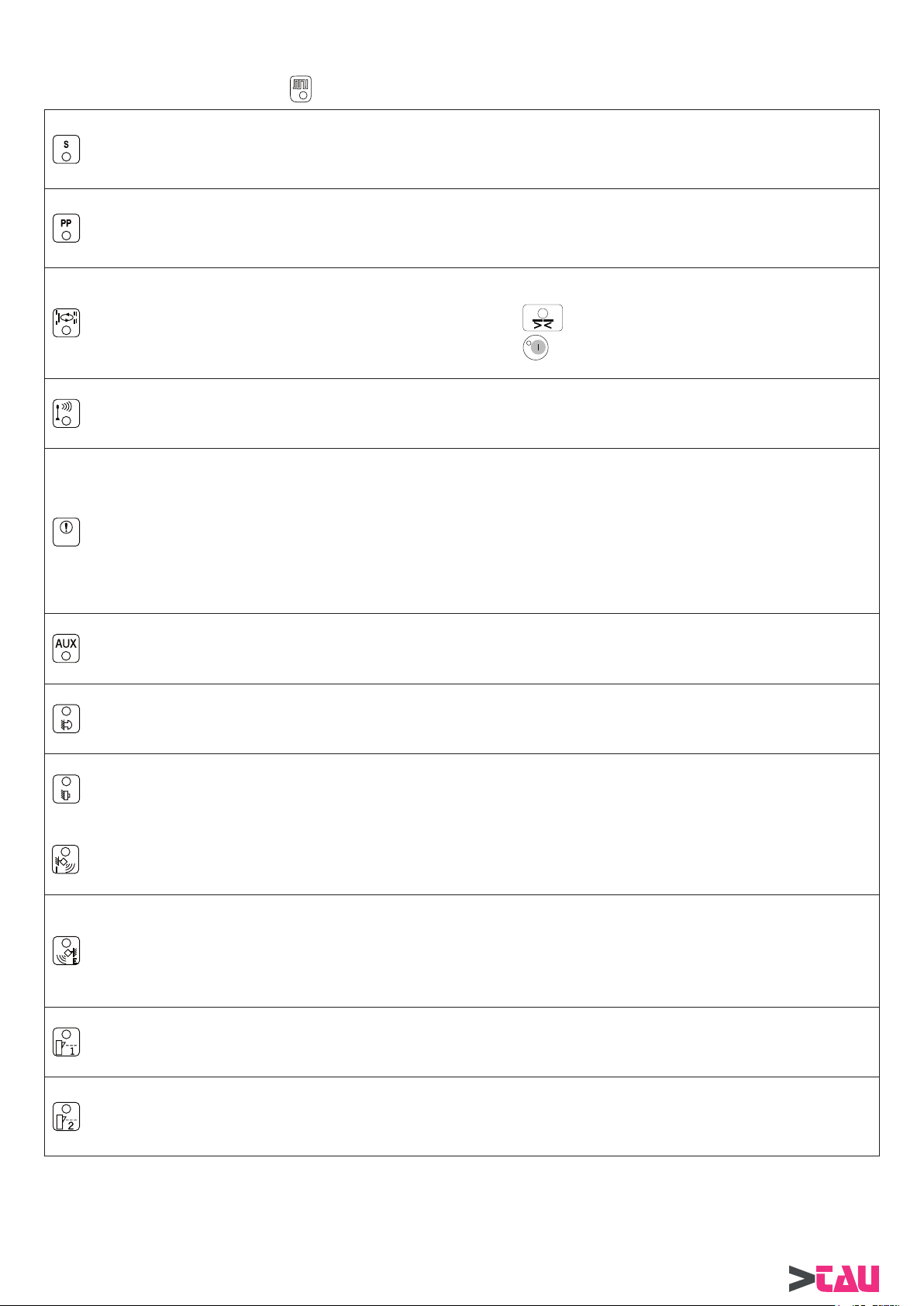
6) FUNZIONI RELATIVE AL DIP SWITCH S1
Impostare le funzioni agendo direttamente sul dip switch S1 della centralina, oppure sulla spia del selettore DOORPROGB (per le
impostazioni da selettore digitale DOORPROGB vedi par. 9.1).
Selettore / Centralina
DIP 1
DIP 2
DIP 3
DIP 4
DIP 5
ATTENZIONE!!
Questo DIP deve essere impostato prima di eseguire il SETTAGGIO INIZIALE descritto nel capitolo 4.
DIP 6
ON = Push & Go attiva; apertura della porta mediante spinta manuale.
OFF = Push & Go esclusa.
ON = Wind stop attiva; impedisce l’apertura indesiderata della porta in presenza di correnti d’aria.
OFF = Wind stop esclusa.
ON = abilita la funzione ciclica (apertura e chiusura ripetute).
OFF = funzione ciclica esclusa.
ON = uscita elettroserratura abilitata (vedi a par.8 i potenziometri TM9 e TM10 che consentono di ottimizzare il
funzionamento con elettroserratura).
OFF = uscita elettroserratura esclusa.
ON = FUNZIONAMENTO BRINK: APERTURA A MOTORE, CHIUSURA A MOTORE.
Si consiglia di utilizzare questa funzione per le porte che in fase di chiusura possono trovarsi sottoposte
alla forza del vento e in tutti quei casi in cui la sola spinta della molla potrebbe non garantire una chiusura
completa della porta.
OFF = FUNZIONAMENTO BRINKS: APERTURA A MOTORE, CHIUSURA A MOLLA.
ON = attiva il ciclo di settaggio iniziale (vedi par.4); consente l’ascolto della limitazione di potenza tramite
buzzer.
OFF = esclude l’ascolto della limitazione di potenza.
PARTE ELETTRONICA
DIP 7
DIP 8
DIP 9
DIP 10
DIP 11 (selezionabile solo da selettore digitale DOORPROGB)
ON = impostazione del programma di lavoro dal selettore digitale DOORPROGB (vedi par. 9).
OFF = impostazione del programma di lavoro dal commutatore di scelta funzioni (vedi par. 5.1) o dal selettore manuale DOORSELFB
(vedi par. 5.2).
DIP 12 (selezionabile solo da selettore digitale DOORPROGB)
ON = abilita la regolazione delle funzioni (dip-switch S1) e dei potenziometri (da TM1 a TM5) dal selettore digitale DOORPROGB.
OFF = abilita la regolazione delle funzioni (dip-switch S1) e dei potenziometri (da TM1 a TM5) dalla centralina LGN.
ON = condizione di porta aperta con commutatore di scelta funzioni su “||”.
OFF = condizione di blocco notte con commutatore di scelta funzioni su “||”.
ON = funzione di cortesia per disabili. Per la descrizione del funzionamento consultare il paragrafo 10.
OFF = funzione disabili esclusa.
ON = selezionando il programma di lavoro BLOCCO NOTTE, la porta apre e resta aperta 10” prima di
richiudere
OFF = selezionando il programma di lavoro BLOCCO NOTTE, la porta non apre.
In BLOCCO NOTTE, la porta può essere aperta solo con l’ingresso di EMERGENZA.
ON = incrementa automaticamente il tempo di pausa se la porta non riesce a chiudere a causa dell’elevato fl usso
di persone.
OFF = tempo di pausa costante.
T utte le regolazioni del dip-switch S2, dei potenziometri TM6, TM7, TM8, TM9, TM10 e del MENU’ TECNICO si effettuano solamente
per mezzo del selettore digitale DOORPROGB.
BRINK Series - Italiano
17
Page 18
7) FUNZIONI RELATIVE AL DIP SWITCH S2 (solo dal selettore digitale DOORPROGB)
Impostare le funzioni agendo sulla spia del selettore digitale DOORPROGB (vedi par.9.1).
ON = Funzione PASSO-PASSO attiva; un impulso apre, un secondo impulso chiude.
DIP 1
Gli ingressi abilitati sono START e l’EMERGENZA.
OFF = Funzione PASSO-PASSO esclusa.
PARTE ELETTRONICA
DIP 2
DIP 3 (attivo solo se il successivo DIP 4 = ON)
DIP 4
DIP 5 = RITARDO ANTA ALLA PARTENZA PER PORTA BATTENTE A DUE ANTE (vedi par.13).
Regolazione necessaria nel caso di ante sovrapposte.
DIP 6
ON = SGANCIO ELETTROSERRATURA IN PORTA LIBERA ABILITATO.
Per la descrizione del funzionamento consultare il paragrafo 11.
OFF = SGANCIO ELETTROSERRATURA IN PORTA LIBERA ESCLUSO.
ON = APERTURA PEDONALE CON SELETTORE IN
OFF = APERTURA PEDONALE CON SELETTORE IN
ON = APERTURA PEDONALE ABILITATA (vedi par.14)
OFF = APERTURA PEDONALE ESCLUSA (vedi par.14)
ON = RITARDO ANTA INSERITO SIA IN APERTURA CHE IN CHIUSURA.
Le centraline MASTER/SLAVE lavorano con un tempo di ritardo anta predefi nito, che può essere variato
tramite il selettore digitale DOORPROGB, entrando nel MENU’ TECNICO e modifi cando i parametri ai
punti 13 (ritardo anta in apertura) e 14 (ritardo anta in chiusura). Considerare che la centralina MASTER è
ritardata alla chiusura, mentre la centralina SLAVE è ritardata all’apertura.
OFF = RITARDO ANTA ESCLUSO e partenza contemporanea delle ante.
ON = impostazione della centralina come SLAVE (vedi par. 13).
OFF = impostazione della centralina come MASTER (vedi par. 13).
(vedi par.14)
(vedi par.14)
DIP 7
DIP 8 = La combinazione di questi dip switch determina la modalità di lavoro del modulo fotocellule DOORFOTO1.
Per la descrizione del funzionamento consultare il paragrafo 12.
DIP 9 = Se non viene utilizzata la fotocellula DOORFOTO1, mantenere i dip in OFF, come da default.
DIP 10
DIP 11 ON = Ripristino valori di default del MENU’ TECNICO (vedi par.18 FUNZIONI AVANZATE - MENU’TECNICO)
DIP 12 = RESET della centralina:
entrare in programmazione, posizionare ON il dip 12 e uscire salvando il dato come descritto nel Paragrafo 9.1.
La centralina viene resettata e il dip torna automaticamente nello stato OFF.
ON = MODALITA’ DI LAVORO “PORTA DOPPIA ANTA” (vedi par. 13).
OFF = MODALITA’ DI LAVORO “PORTA SINGOLA ANTA”.
ON = L’ingresso di RADAR INTERNO comanda la sola chiusura.
L’ingresso di RADAR ESTERNO comanda la sola apertura.
Dopo un’apertura comandata da RADAR ESTERNO, la chiusura non è automatica, ma avviene con un
intervento di RADAR INTERNO.
OFF = Funzionamento standard degli ingressi radar.
18
BRINK Series - Italiano
Page 19
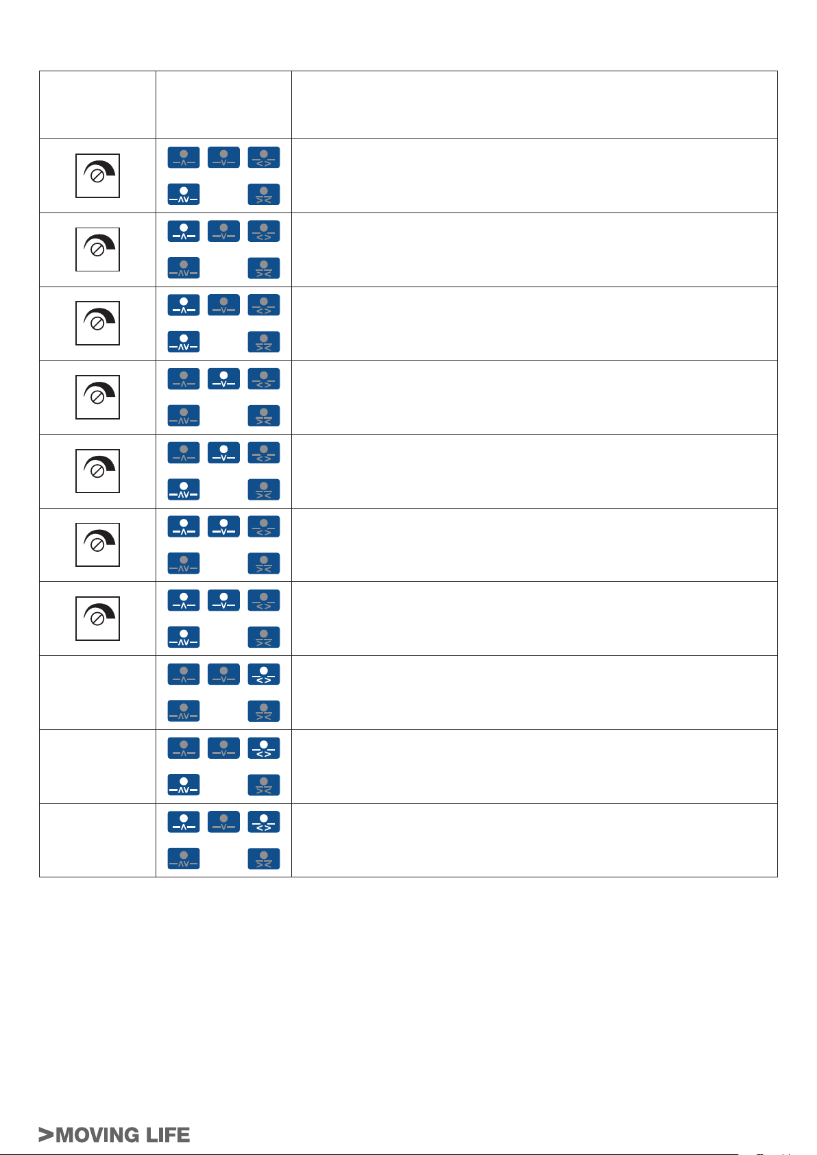
8) REGOLAZIONI DEI POTENZIOMETRI
REGOLAZIONE DA
REGOLAZIONE
DA CENTRALINA
SELETTORE
DOORPROGB
N.B.: Il simbolo di programma
chiaro indica il led acceso
PARAMETRI DI LAVORO
TM1
TM2
TM3
TM4
TM5
TM6
Velocità di apertura
Velocità di chiusura
Distanza di esclusione sensore di sicurezza in apertura
Limitazione della potenza di spinta
Tempo di pausa - max 20” - min 0
Tensione di mantenimento in chiusura
PARTE ELETTRONICA
Intensità della forza di Wind stop
TM7
TM8
TM9
TM10
IMPORTANTE:
Le regolazioni non possibili dalla centrale per assenza di ulteriori potenziometri, si effettuano solamente dal selettore digitale
DOORPROGB.
Per la modalità di regolazione dei parametri descritti da selettore DOORPROGB, consultare il Paragrafo 9.1.
Distanza di attivazione Push & Go
Intensità della spinta fi nale in chiusura per aggancio elettroserratura
Potenza del colpo di 0,5” in chiusura prima dell’apertura per sgancio elettroserratura. Al valore minimo colpo in chiusura escluso con elettroserratura attivata
contemporaneamente alla partenza del motore.
BRINK Series - Italiano
19
Page 20
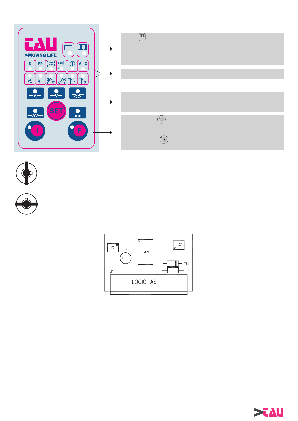
9) IL SELETTORE DIGITALE DOORPROGB
Se il led è acceso fi sso o lampeggiante signifi ca che non vi è comunicazione
tra selettore e centralina.
In questo caso controllare il collegamento elettrico.
PARTE ELETTRONICA
Verifi care la presenza del modulo LOGIC TAST.
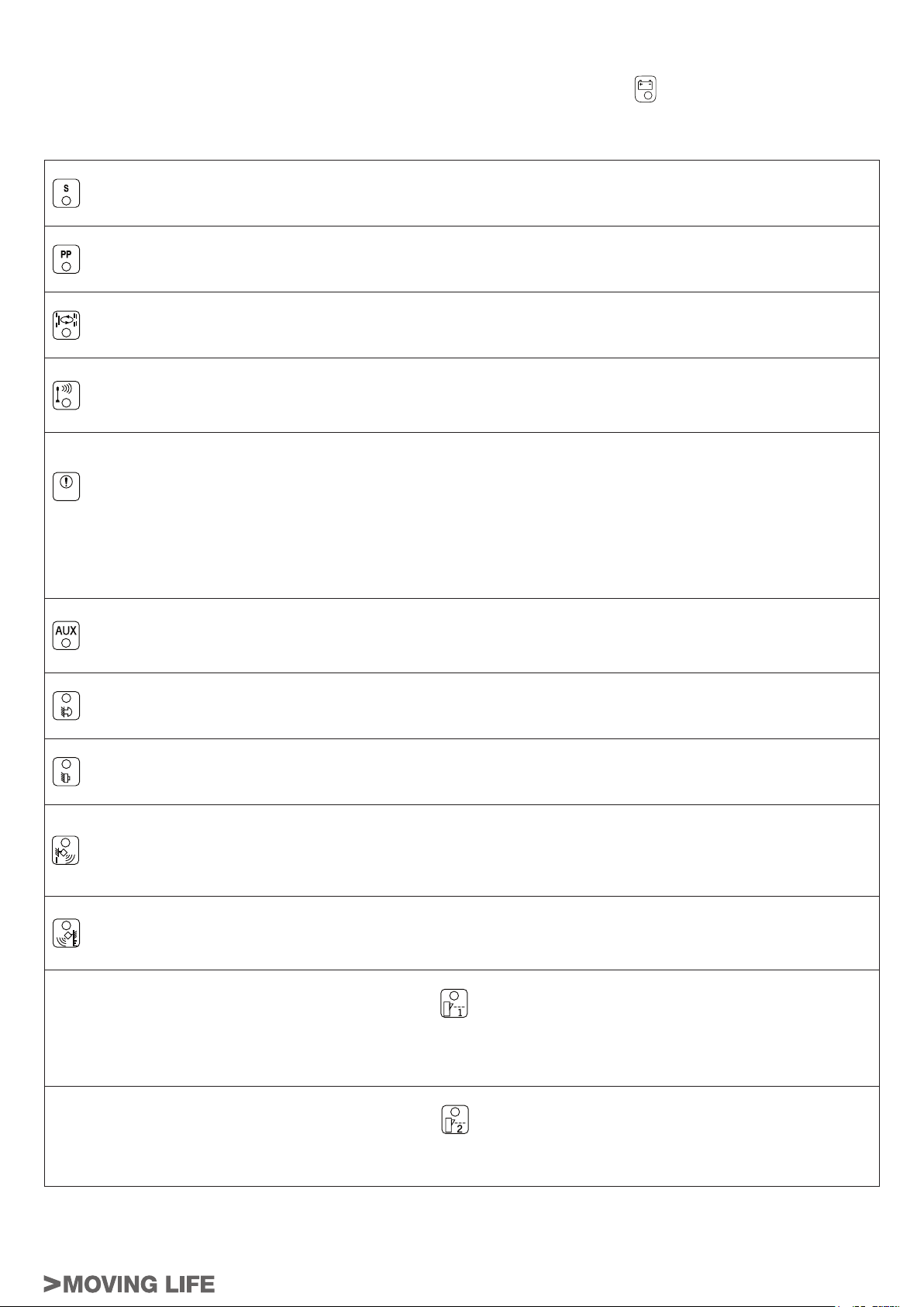
Segnalazioni dello stato degli ingressi.
Il led acceso indica che l’ingresso è impegnato.
Selezione del programma di lavoro: premere il pulsante SET per cambiare il tipo
di programma.
In senso orario, traffi co nei 2 sensi, solo in uscita, solo in entrata, porte sempre
aperte, blocco notte.
Premendo il tasto (led verde acceso) si attiva la funzione di porta libera.
Il motore non viene alimentato ed è possibile muovere la porta manualmente.
Premendo il tasto
inserita dal DIP 1 di S2.
FUNZIONI LIBERE (premendo SET è possibile variare il programma di lavoro)
FUNZIONI BLOCCATE
(led verde acceso) si esclude la funzione passo-passo
LOGIC TAST
All’interno della confezione del selettore digitale DOORPROGB è presente la scheda elettronica LOGIC TAST, che costituisce il modulo
di interfaccia necessario allo scambio di dati tra il selettore digitale DOORPROGB e la centralina elettronica.
La scheda LOGIC TAST deve essere innestata nel connettore J8 della parte LGN della centralina elettronica (vedi fi g.2 al paragrafo 2).
Una morsettiera a 4 poli presente nella confezione del prodotto serve per effettuare il collegamento elettrico tra il selettore DOORPROGB
e la morsettiera M4 della parte CPB-1 della centralina elettronica.
20
BRINK Series - Italiano
Page 21
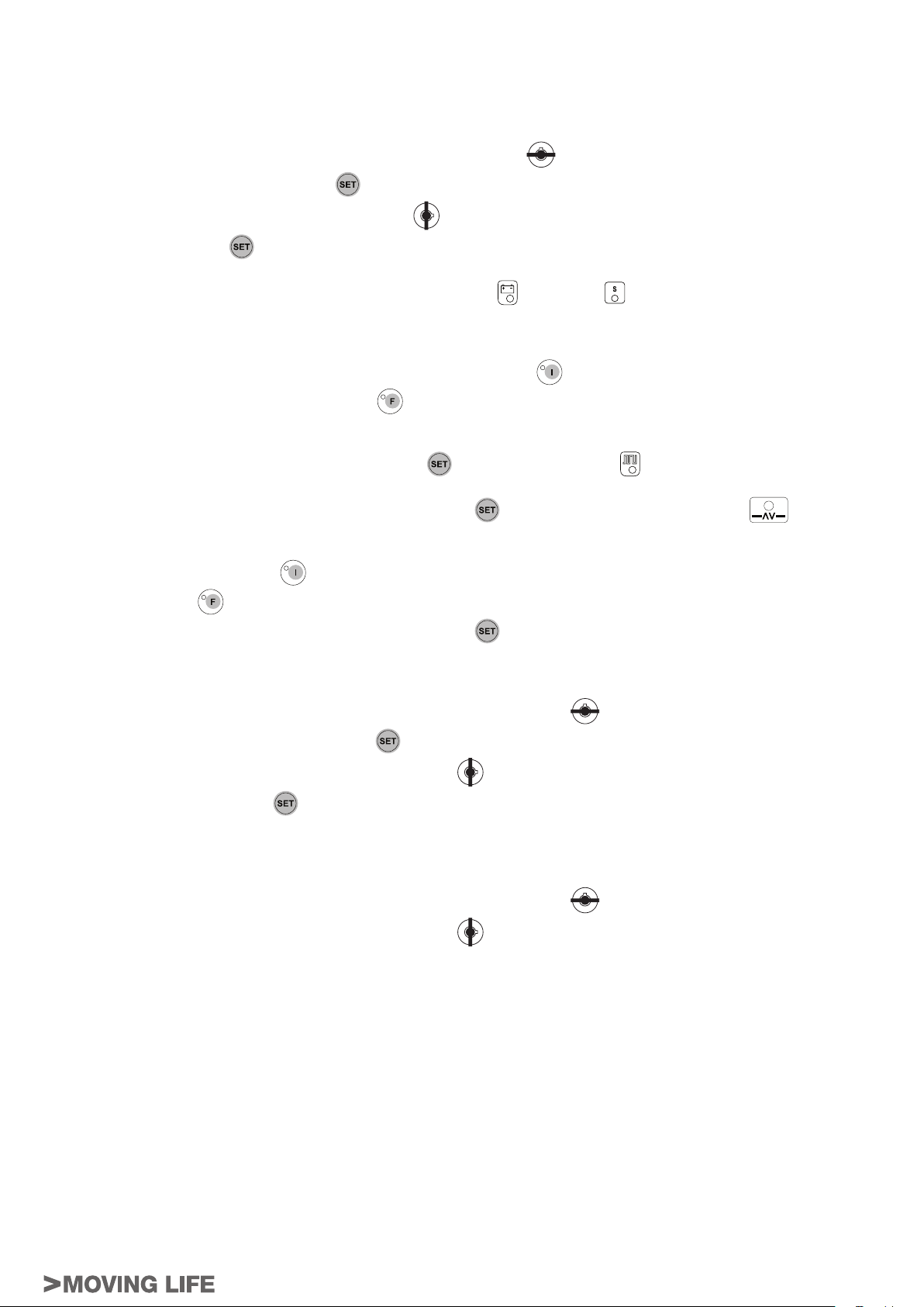
9.1) REGOLAZIONE AUTOMATISMO CON PROGRAMMAZIONE REMOTA DAL SELETTORE DOORPROGB
Per rendere operativa la programmazione remota del dip-switch S1 e dei potenziometri da TM1 a TM5 è necessario posizionare in ON
il DIP12 di S1.
La programmazione di tutti gli altri parametri non dipende dal DIP 12 di S1.
Per entrare in programmazione seguire i seguenti passi:
A) Posizionare la chiave di blocco del selettore in posizione funzioni bloccate
B) Premere e tenere premuto il pulsante SET
C) Riportare la chiave di blocco in posizione funzioni libere
D) Rilasciare il pulsante SET
E) I led gialli degli ingressi si accendono in sequenza da sinistra verso destra per indicare il caricamento dati (UPLOAD).
F) Una volta terminato l’UPLOAD si accenderà il led rosso di BATTERIA
G) Il led di batteria indica che si sta operando sul DIP-SWITCH S1 ed il led giallo indica:
G1) il DIP1 di S1 in posizione ON se il led è acceso fi sso.
G2) il DIP1 di S1 in posizione OFF se il led è lampeggiante.
H) Per cambiare lo stato del DIP (ON - OFF) premere il pulsante di porta libera
I) Per portarsi sul DIP2 di S1 premere il pulsante F1
L) Ripetere quest’ultima operazione per posizionarsi sugli altri DIP di S1.
M) Fare riferimento ai paragrafi 6 e 7 per il signifi cato dei DIP.
N) Per operare sul DIP-SWITCH S2 premere il pulsante SET
O) Ripetere le operazioni come per il MINIDIP S1 per selezionare e cambiare lo stato ai singoli DIP.
P) Per portarsi sul POTENZIOMETRO TM1 premere il pulsante SET
Q) Quando si sta operando sui potenziometri i led degli ingressi formano una scala per indicare il valore impostato.
R) Per cambiare il valore del potenziometro selezionato premere:
R1) Il pulsante PORTA LIBERA
R2) Il pulsante F1
.
per decrementare il valore.
per incrementare il valore.
del selettore.
.
.
, si accenderà il led LINEA .
, si accenderà il led traffi co nei 2 SENSI .
.
e il led giallo .
.
PARTE ELETTRONICA
S) Per portarsi sul POTENZIOMETRO TM2 premere il pulsante SET
T) Ripetere quest’ultima operazione per posizionarsi sugli altri potenziometri.
U) Fare riferimento al paragrafo 8 per il signifi cato dei potenziometri.
V) Per uscire dalla programmazione e memorizzare i valori modifi cati eseguire le seguenti operazioni:
V1) Posizionare la chiave di blocco del selettore in posizione funzioni bloccate .
V2) Premere e tenere premuto il pulsante SET
V3) Riportare la chiave di blocco in posizione funzioni libere
V4) Rilasciare il pulsante SET
V5) I led degli ingressi si accendono in sequenza da destra verso sinistra indicando il DOWNLOAD.
V6) Una volta terminato il DOWNLOAD dalla centralina vengono emessi 2 bip.
V7) Il selettore si riposiziona sul funzionamento normale.
Z) Per uscire dalla programmazione senza memorizzare i valori modifi cati eseguire le seguenti operazioni:
Z1) Posizionare la chiave di blocco del selettore in posizione funzioni bloccate
Z2) Riportare la chiave di blocco in posizione funzioni libere
Z3) Il selettore si riposiziona sul funzionamento normale e dalla centralina viene emesso 1 bip.
.
del selettore.
.
.
.
.
10) FUNZIONAMENTO DI CORTESIA PER DISABILI
• Posizionando il dip switch 8 di S1 nello stato ON si abilita la funzione di cortesia per disabili.
Due ingressi della centralina BRINK, lo START e l’EMERGENZA, sono dedicati all’uso di appositi pulsanti di apertura, adatti per
essere utilizzati da persone disabili.
• Dopo un’apertura comandata dalla persona disabile tramite l’ingresso di START o EMERGENZA, si ottiene la richiusura automatica
della porta dopo il tempo di pausa impostato dal potenziometro TM5 e l’ingresso di fotocellula di sicurezza in chiusura è attivo.
Se durante l’ultimo tratto della manovra di apertura o nel periodo di pausa a porta aperta viene impegnata la fotocellula di sicurezza
in chiusura , a causa dell’attraversamento della porta da parte della persona disabile, si ottiene una riduzione del tempo di pausa a
tre secondi (anche se impostato per un tempo superiore) e la conseguente richiusura della porta.
• L’apertura della porta causata dalla spinta manuale con funzione di push & go abilitata (DIP 1 di S1 ON), oppure dalla rilevazione dei
radar interno o esterno se utilizzati, implica una richiusura immediata della porta con tempo di pausa al valore minimo (anche se il
potenziometro TM5 è impostato per un tempo superiore) e l’ingresso di fotocellula di sicurezza in chiusura non attivo.
BRINK Series - Italiano
21
Page 22
11) SGANCIO ELETTROSERRATURA IN PORTA LIBERA
Posizionando il dip switch 2 di S2 nello stato ON (vedi par.7) tramite il selettore DOORPROGB (vedere la procedura al par.9.1) si abilita
lo sgancio dell’elettroserratura in porta libera.
Attivando la funzione PORTA LIBERA
porta è chiusa e al termine di ogni chiusura, per predisporre la porta ad essere aperta alla successiva spinta manuale.
Utilizzando il selettore digitale DOORPROGB e premendo il tasto
dell’elettroserratura alla fi ne di ogni chiusura della porta in tutte le funzioni giorno.
PARTE ELETTRONICA
Ripremendo il tasto
ATTENZIONE!
Si sconsiglia l’attivazione della funzione (DIP 2 S2/ON) con l’impiego del selettore meccanico DOORSELFB, in quanto la variazione del
programma di lavoro della porta può causare uno sgancio indesiderato dell’elettroserratura, anche se la funzione scelta non è PORTA
LIBERA.
Ciò è dovuto alla commutazione elettrica dei segnali sugli ingressi della centralina, durante lo spostamento della manopola del selettore
DOORSELFB.
(led verde spento) si esclude questa opzione.
tramite il selettore di programma, si ottiene un impulso di sgancio sull’elettroserratura se la
(led verde acceso) è possibile ottenere uno sgancio automatico
12) SCHEDA FOTOCELLULE DOORFOTO1
INSERIMENTO DELLA SCHEDA NEL CONNETTORE PRESENTE SULLA SCHEDA MADRE
Inserire la scheda fotocellule nel connettore J9 (PHOTOCELL CONTROL) della scheda madre LGN.
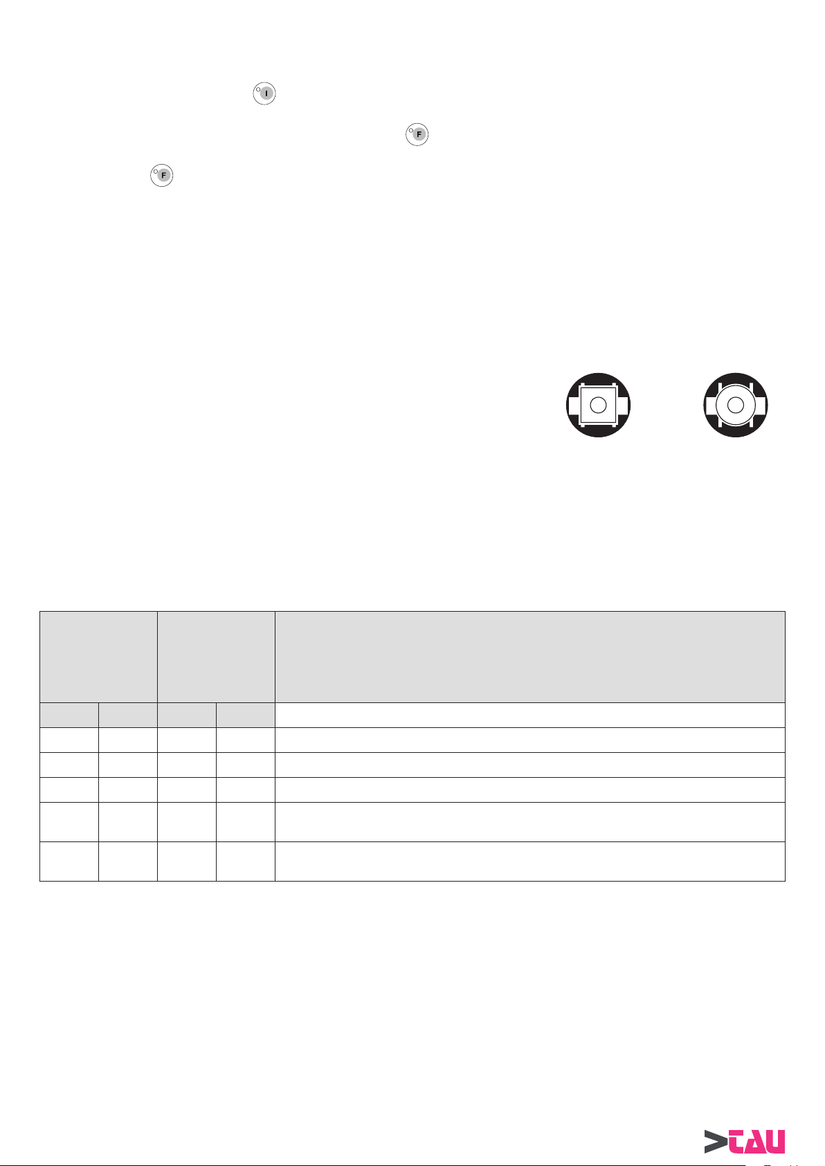
COME DISTINGUERE LE CAPSULE TRASMITTENTI DALLE RICEVENTI
Ogni coppia di fotocellule è composta da una capsula ricevente ed una trasmittente con
l’apposito cavo completo di mini connettore per una veloce e pratica sostituzione. Le
capsule riceventi sono di forma quadrata sulla parte dove esce il cavo di collegamento
mentre le trasmittenti sono di forma rotonda. Per entrambe è necessario un foro di diametro
11 mm per il fi ssaggio. I cavi sono marchiati all’ inizio ed alla fi ne con la scritta TX per le
trasmittenti ed RX per le riceventi.
SELEZIONE DEL NUMERO DI COPPIE DI FOTOCELLULE UTILIZZATE
La scheda DOORFOTO1 è in grado di gestire fi no a 3 coppie di fotocellule, di cui 2 coppie ( FT1/FR1 e FT2/FR2 ) sono dedicate al
comando di apertura della porta e lavorano nello stesso modo degli ingressi radar, mentre la terza ( FT3/FR3 ) lavora come fotocellula
di sicurezza in chiusura.
In base al numero di coppie di fotocellule utilizzate ed al loro effettivo impiego sulla porta, è necessario impostare correttamente la
combinazione dei dip switch sulla centralina BRINK e sul modulo DOORFOTO1.
A questo proposito consultare attentamente la tabella seguente.
RICEVENTE TRASMITTENTE
TABELLA 12.1
DIP SWITCH S2
CENTRALINA
BRINK
(da impostare
tramite selettore
DOORPROGB)
DIP 8 DIP 9 DIP 1 DIP 2
OFF ON OFF ON 1 COPPIA DI SICUREZZA IN CHIUSURA (FT3/FR3)
ON ON OFF OFF
ON ON ON OFF 2 COPPIE COME COMANDO DI APERTURA (FT1/FR1 e FT2/FR2)
ON ON OFF ON
ON ON ON ON
MODALITA’ DI LAVORO DELLE COPPIE DI FOTOCELLULE
FT1/FR1: stesso funzionamento dell’ingresso RADAR INTERNO.
FT2/FR2: stesso funzionamento dell’ingresso RADAR ESTERNO.
FT3/FR3: fotocellula di sicurezza; interviene in chiusura, invertendo il senso di marcia.
DIP SWITCH SW1
SCHEDA
FOTOCELLULE
DOORFOTO1
NUMERO DI FOTOCELLULE IMPIEGATE E LORO UTILIZZO
1 COPPIA COME COMANDO DI APERTURA (FT1/FR1)
1 COPPIA COME COMANDO DI APERTURA (FT1/FR1)
e 1 COPPIA DI SICUREZZA IN CHIUSURA (FT3/FR3)
2 COPPIE COME COMANDO DI APERTURA (FT1/FR1 e FT2/FR2)
e 1 COPPIA DI SICUREZZA IN CHIUSURA (FT3/FR3)
COLLEGAMENTI CAPSULE RICEVENTI E TRASMITTENTI
Per evitare interferenze dovute all’irradiamento diretto del sole si consiglia di posizionare le capsule riceventi sul lato più protetto dai
raggi solari.
22
BRINK Series - Italiano
Page 23

M5
FT3
FT2
FT1
+
Morsettiera M5 ( FT1 - FT2 - FT3- + )
FT3 = ingresso CAPSULA TRASMITTENTE 3 (CAVO NERO)
FT2 = ingresso CAPSULA TRASMITTENTE 2 (CAVO NERO)
FT1 = ingresso CAPSULA TRASMITTENTE 1 (CAVO NERO)
+ = ALIMENTAZIONE PER TUTTE LE CAPSULE TRASMITTENTI (CAVI BLU)
Morsettiera M6 ( FR1 - FR2 - FR3- VCC - GND )
FR3
FR3 = ingresso CAPSULA RICEVENTE 3 (CAVO MARRONE)
FR2
FR1
M6
VCC
GND
REGOLAZIONE DELLA SENSIBILITÀ DELLE CAPSULE
Una volta posizionate le capsule si deve regolare la sensibilità delle stesse
per mezzo del potenziometro posizionato sulla scheda. Per un corretto funzionamento agire come segue:
1) Tarare il potenziometro in base alla distanza tra le capsule (vedi fi gura a
lato).
2) Se i led delle capsule utilizzate sono spenti la sensibilità è corretta.
3) Se i led sono accesi, ruotare lentamente verso il massimo il potenziometro
fi no a che i led non si spengono completamente.
4) Controllare che interrompendo il fascio infrarosso delle fotocellule i led rela-
tivi si accendano.
FR2 = ingresso CAPSULA RICEVENTE 2 (CAVO MARRONE)
FR1 = ingresso CAPSULA RICEVENTE 1 (CAVO MARRONE)
VCC = ( + ) ALIMENTAZIONE PER TUTTE LE CAPSULE RICEVENTI (CAVI BLU)
GND = ( - ) ALIMENTAZIONE PER TUTTE LE CAPSULE RICEVENTI (CAVI NERI)
13) PORTA BATTENTE A DUE ANTE
POTENZIOMETRO
AL MINIMO
fi no a 2 metri
DIP SWITCH SW1
POTENZIOMETRO
L1 L2 L3
SENSITIVITY
A METÀ
da 2 a 4 metri
MAX
POTENZIOMETRO
AL MASSIMO
da 4 a 6 metri
MIN
SENSITIVITY
PARTE ELETTRONICA
Utilizzando due operatori BRINK è possibile gestire il funzionamento di una porta a doppia anta.
Consultare attentamente i “DISEGNI P ARTE MECCANICA” all’inizio di questo manuale per determinare le quote di fi ssaggio, la direzione
di apertura dell’anta e il peso massimo consentito in funzione della lunghezza dell’anta. Il sistema è costituito dalla centralina principale
che deve essere confi gurata come MASTER, il cui compito è gestire il funzionamento generale della porta e dalla seconda centralina,
impostata come SLAVE, che riceve ordini e informazioni dalla MASTER.
Nel caso di una porta in cui le ante si sovrappongono in chiusura applicare l’operatore confi gurato come MASTER all’anta battente che
si sovrappone all’altra (cioè l’anta che apre per prima e chiude per ultima).
BRINK Series - Italiano
23
Page 24
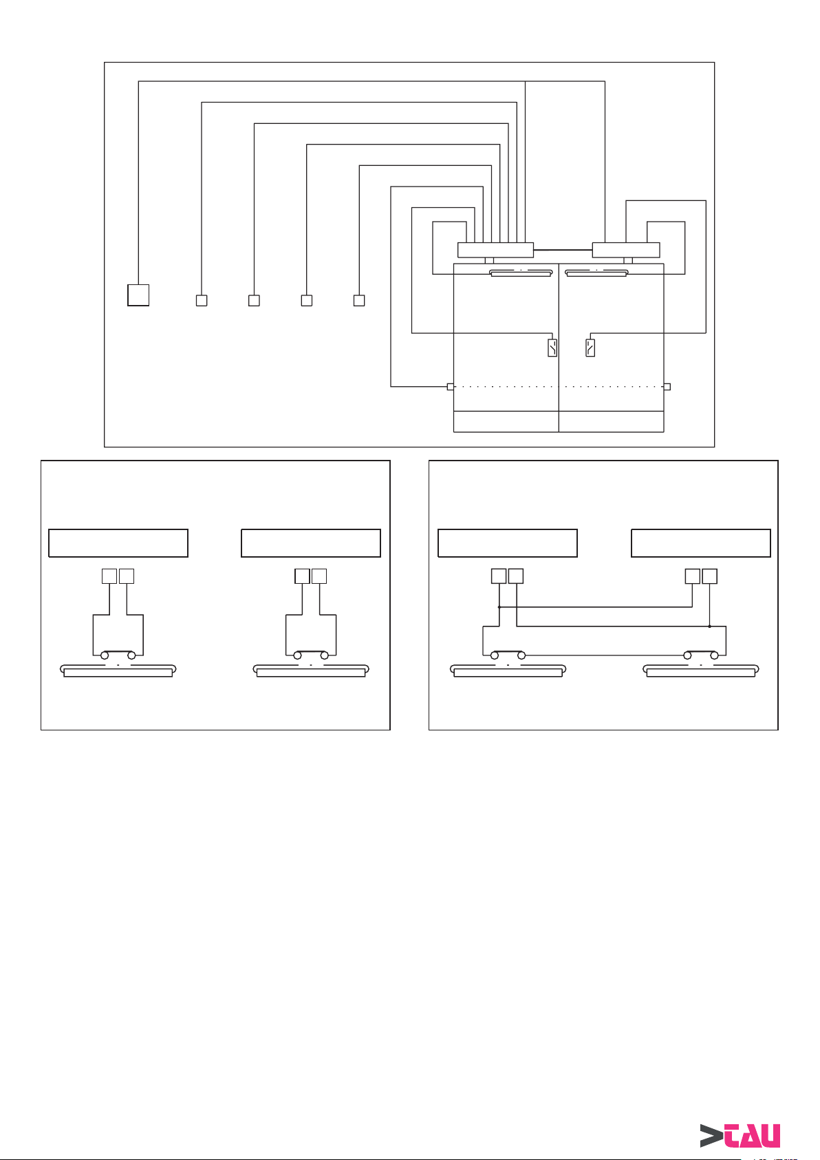
13.1) COLLEGAMENTI ELETTRICI (vedi schema di principio a fi gura 3)
PARTE ELETTRONICA
MASTER
CABLAGGIO
WR3MS
SLAVE
LINEA
ALIMENTAZIONE
230 Vac
Fig. 3
ARRESTO SEPARATO DELLE ANTE ALLA RILEVAZIONE DEL
OPERATORE MASTER OPERATORE SLAVE
SENSORE DI SICUREZZA IN APERTURA
SELETTORE
FUNZIONI
RADAR EMERGENZA
START
5757 57
FOTOCELLULA
SENSORE
ELETTROBLOCCO
MASTER
ANTA1 (MASTER) ANTA2 (SLAVE)
ARRESTO UNIFICATO DELLE ANTE ALLA RILEVAZIONE DEL
OPERATORE MASTER
SENSORE DI SICUREZZA IN APERTURA
5
7
SENSORE
ELETTROBLOCCO
SLAVE
OPERATORE SLAVE
57
SENSORE
ANTA “MASTER”
SENSORE
ANTA “SLAVE”
Fig. 4
SENSORE
ANTA “MASTER”
SENSORE
ANTA “SLAVE”
13.1.1) OPERATORE CON CENTRALINA MASTER
Effettuare i collegamenti elettrici alla centralina MASTER seguendo quanto descritto nel paragrafo 1) del presente manuale, considerando
che tutti gli ingressi di comando e di sicurezza (dal morsetto 1 al morsetto 11) sono attivi sull’operatore MASTER. Per quanto riguarda
il sensore di sicurezza in apertura mod. DOORSS340, tenere presente che le centraline MASTER e SLAVE ne gestiscono in maniera
separata la rilevazione (vedi fi g.4). Questo signifi ca che il sensore di sicurezza applicato all’anta comandata dall’operatore MASTER
deve essere collegato tra i morsetti 5-7 della centralina MASTER e agirà solamente sul comportamento di quest’ultima. Se invece,
utilizzando un sensore di sicurezza in apertura per ogni anta, si volesse ottenere l’arresto completo della porta indipendentemente dal
sensore che ha rilevato l’ostacolo, diventa necessario collegare i contatti N.C. dei due sensori in serie fra di loro e portare il contatto
ottenuto ai morsetti 5-7 delle centraline MASTER e SLAVE effettuando un collegamento parallelo.
L’elettroserratura deve essere collegata alla centralina MASTER.
Se la porta dispone di doppia elettroserratura per bloccare singolarmente ogni anta, collegare alla centralina MASTER la sola
elettroserratura che riguarda l’anta comandata dall’operatore MASTER.
Il selettore meccanico di programma DOORSELFB (vedi paragrafo 5.2) deve essere collegato alla centralina MASTER.
Il selettore digitale DOORPROGB (vedi paragrafo 9) deve essere collegato alla centralina MASTER per poter selezionare il programma
di lavoro desiderato.
13.1.2) OPERATORE CON CENTRALINA SLAVE
Alimentare la centralina SLAVE a 230V a.c. sulla morsettiera M1.
Il sensore di sicurezza in apertura mod. DOORSS340 applicato all’anta comandata dall’operatore SLAVE deve essere collegato tra i
morsetti 5-7 della centralina SLAVE e agirà solo sul comportamento di quest’ultima (vedi fi gura 4).
Se la porta dispone di doppia elettroserratura per bloccare singolarmente ogni anta, collegare alla centralina SLA VE la sola elettroserratura
che riguarda l’anta comandata dall’operatore SLAVE.
24
BRINK Series - Italiano
Page 25

IMPORTANTE!
Le centraline MASTER e SLAVE devono essere collegate fra di loro attraverso il cablaggio mod.WR3MS per ottenere la
comunicazione e lo scambio dei dati.Connettere i due terminali presenti ai capi del cavo ai connettori siglati J13, presenti a
bordo delle centraline (parte logica LGN).
13.2) INSTALLAZIONE DELL’AUTOMAZIONE
Seguire scrupolosamente i passi descritti di seguito per effettuare l’installazione nel modo corretto:
A) Fissare i due operatori BRINK rispettando le quote e la direzione di apertura dell’anta riportate nei disegni della parte meccanica di
questo manuale.
B) SOLO PER LA VERSIONE “BRINK-S”:
Effettuare la connessione dei braccetti, scegliendo il carico ideale della molla in funzione delle caratteristiche dell’anta come descritto
nel paragrafo 8.0 della parte meccanica.
C) Effettuare il settaggio iniziale come descritto al paragrafo 4), procedendo separatamente, prima con l’operatore che verrà confi gurato
come MASTER, quindi con lo SLAVE. Nel caso di porte con ante sovrapposte in chiusura, mantenere aperta l’anta comandata
dall’operatore MASTER al termine del settaggio iniziale, per consentire all’anta controllata dall’operatore SLAVE di muoversi
liberamente nel corso del proprio settaggio iniziale.
D) Portare entrambe le ante nella condizione di chiusura e impostare le funzioni adatte alla modalità di lavoro per porta a doppia anta; a
questo proposito seguire attentamente il capitolo successivo.
13.3) FUNZIONI e REGOLAZIONI
Dopo aver terminato l’opera di installazione e completato il settaggio iniziale, proseguire la messa a punto dell’automazione impostando
i parametri necessari alla sincronizzazione del sistema.
13.3.1) COME AGIRE SULL’OPERATORE MASTER
A) Collegare il selettore digitale DOORPROGB alla centralina dedicata al ruolo di MASTER, senza dimenticare di innestare il modulo
LOGIC TAST nel connettore J8 della centralina.
B) Entrare in programmazione dal selettore DOORPROGB (vedere la procedura al Paragrafo 9.1) e portarsi sul dip-switch S2 (vedi
paragrafo 7).
C) Se l’automazione richiede il ritardo delle ante alla partenza (il caso delle ante sovrapposte) impostare il dip 5 ON, se le ante devono
muoversi contemporaneamente impostare il dip 5 OFF.
D) Impostare il dip 6 OFF per confi gurare la centralina come MASTER.
E) Impostare il dip 7 ON per abilitare la centralina alla modalità di lavoro “PORTA DOPPIA ANTA”.
F) Uscire dalla programmazione dal selettore DOORPROGB memorizzando i dati (vedere la procedura al Paragrafo 9.1); dalla centralina
vengono emessi 2 bip.
G) A questo punto la centralina è predisposta a lavorare come MASTER in una porta a doppia anta.
PARTE ELETTRONICA
13.3.2) COME AGIRE SULL’OPERATORE SLAVE
A) Collegare il selettore digitale DOORPROGB alla centralina dedicata al ruolo di SLAVE, senza dimenticare di innestare il modulo
LOGIC TAST nel connettore J8 della centralina.
B) Entrare in programmazione dal selettore DOORPROGB (vedere la procedura al Paragrafo 9.1) e portarsi sul dip-switch S2 (vedi
paragrafo 7).
C) Impostare il dip 6 ON per confi gurare la centralina come SLAVE.
D) Impostare il dip 7 ON per abilitare la centralina alla modalità di lavoro “PORTA DOPPIA ANTA”.
E) Uscire dalla programmazione dal selettore DOORPROGB memorizzando i dati (vedere la procedura al Paragrafo 9.1); dalla centralina
vengono emessi 2 bip.
F) A questo punto la centralina è predisposta a lavorare come SLAVE in una porta a doppia anta.
13.3.3) VERIFICA DEL FUNZIONAMENTO DELLA PORTA
Dopo aver alimentato i due operatori, selezionare le funzioni desiderate attraverso i dip switch e regolare i potenziometri seguendo
le descrizioni ai paragrafi 6,7 e 8, tenendo presente che alcune impostazioni devono essere effettuate solo sulla centralina MASTER,
mentre altre devono essere eseguite sia sulla MASTER che sulla SLAVE.
A questo proposito consultare attentamente la TABELLA del capitolo 15, in cui, per ogni parametro, viene indicato se la
regolazione riguarda entrambe le centraline o la sola MASTER.
• Se l’automazione prevede il ritardo delle ante alla partenza, tarare il potenziometro TM2 (velocità di chiusura) della centralina MASTER
ad un livello inferiore (circa la metà) rispetto al potenziometro TM2 della centralina SLAVE. Tuttavia, l’operatore MASTER partirà in
chiusura con una velocità ridotta in modo che l’operatore SLAVE possa entrare nella fase di rallentamento fi nale dell’anta senza
correre il rischio di raggiungere il punto di sovrapposizione delle ante durante la corsa. In ogni caso, se le ante durante la fase di
chiusura dovessero avvicinarsi fra di loro al di sotto del ritardo impostato, a causa, per esempio, di un attrito improvviso, si otterrebbe
un’inversione del senso di marcia in apertura.
• Infi ne scegliere il programma di lavoro desiderato per mezzo del dispositivo di scelta funzioni utilizzato (selettore meccanico
DOORSELFB, selettore digitale DOORPROGB o il semplice commutatore di scelta funzioni), ricordando che quest’ultimo dovrà
essere collegato alla centralina Master.
• Controllare ora la movimentazione della porta attivando la manovra di apertura ed accertarsi del buon funzionamento di tutte le parti
di comando e di sicurezza dell’automazione.
Se si volesse variare il ritardo fra le ante preimpostato, servirsi del selettore digitale DOORPROGB, collegarlo alla centralina MASTER,
entrare nel MENU’TECNICO (vedi par.18 MENU’TECNICO) e modifi care i valori ai punti 13 (ritardo anta in apertura) e 14 (ritardo anta in
chiusura). Il tempo di pausa con porta aperta deve essere regolato solo dal potenziometro TM5 della centralina MASTER.
BRINK Series - Italiano
25
Page 26

ATTENZIONE:
Se il selettore digitale DOORPROGB dovesse visualizzare la seguente condizione
signifi ca che è stato rilevato un problema di comunicazione tra la centralina MASTER
e la SLAVE. In questo caso controllare le connessioni del cablaggio WR3MS su
entrambe le centraline, verifi care i settaggi impostati sui dip 6 e 7 del dip-switch S2
ed effettuare un reset del sistema.
In assenza del selettore digitale DOORPROGB, la mancanza di comunicazione tra
PARTE ELETTRONICA
le due centraline verrebbe evidenziata dal fatto che l’operatore MASTER resterebbe
aperto e l’operatore SLAVE chiuso.
14) APERTURA PEDONALE
L’apertura pedonale è utilizzabile solamente in una porta battente a due ante, quindi è indispensabile che gli operatori siano predisposti
a lavorare come PORTA DOPPIA ANTA (vedi par.13).
Per abilitare la funzione APERTURA PEDONALE è necessario impostare il dip switch 4 di S2 ON e scegliere, mediante l’impostazione
del dip switch 3 di S2, la condizione in cui rendere operativa la funzione:
A) DIP 3 S2 DIP 4 S2
OFF ON
Selezionando
- In questa condizione lo stato
B) DIP 3 S2 DIP 4 S2
ON ON
Selezionando
- In questa condizione lo stato
Per entrambe i casi A) e B) , l’attivazione di un ingresso RADAR, interno o esterno, causa l’apertura parziale della porta e cioè della sola
anta comandata dall’operatore MASTER (anta pedonale), mentre gli ingressi ST ART o EMERGENZA aprono entrambe le ante MASTER
e SLAVE.
La spinta manuale con il push & go apre solo l’anta pedonale.
sul selettore di programma si abilita la funzione APERTURA PEDONALE.
perde la funzione originaria di porta libera.
sul selettore di programma si abilita la funzione APERTURA PEDONALE.
perde la funzione originaria di blocco notte.
15) ELENCO DEI PARAMETRI DA IMPOSTARE SULLE CENTRALINE
PARAMETRI
DIP-SWITCH S1 MASTER SLAVE
DIP 1 = PUSH & GO
DIP 2 = WIND STOP
DIP 3 = FUNZIONE CICLICA (apertura e chiusura ripetute)
DIP 4 = FUNZIONAMENTO ELETTROSERRATURA
DIP 5 = CHIUSURA A MOTORE (solo versione BRINK-S)
DIP 6 = SETTAGGIO INIZIALE
DIP 7 = PORTA APERTA/BLOCCO NOTTE (con commutatore di scelta funzioni su II)
DIP 8 = FUNZIONAMENTO DI CORTESIA PER DISABILI
DIP 9 = APERTURA 10” CON PROGRAMMA DI LAVORO “BLOCCO NOTTE”
DIP 10 = INCREMENTO AUTOMATICO DEL TEMPO DI PAUSA
DIP 11 = SELEZIONE DEL DISPOSITIVO DI SCELTA FUNZIONI
DIP 12 = REGOLAZIONE FUNZIONI E POTENZIOMETRI DA SELETTORE DIGITALE DOORPROGB
••
••
•
••
••
••
•
•
•
•
•
••
DIP-SWITCH S2 MASTER SLAVE
DIP 1 = FUNZIONAMENTO PASSO-PASSO
DIP 2 = SGANCIO ELETTROSERRATURA IN FUNZIONE PORTA LIBERA
DIP 3 = APERTURA PEDONALE IN PORTA LIBERA (OFF)/BLOCCO NOTTE (ON)
DIP 4 = FUNZIONE APERTURA PEDONALE
DIP 5 = RITARDO ANTE ALLA PARTENZA
DIP 6 = IMPOSTAZIONE CENTRALINA MASTER/SLAVE
DIP 7 = MODALITÀ DI LAVORO “PORTA DOPPIA ANTA”
DIP 8 = MODALITÀ DI LAVORO FOTOCELLULA DOORFOTO1
DIP 9 = MODALITÀ DI LAVORO FOTOCELLULA DOORFOTO1
DIP 10 = FUNZIONAMENTO DEGLI INGRESSI RADAR
DIP 11 = RIPRISTINO VALORI DI DEFAULT DEL MENÙ TECNICO (vedi MENÙ TECNICO)
DIP 12 = RESET DELLA CENTRALINA
26
BRINK Series - Italiano
•
••
•
•
•
••
••
•
•
•
••
•
Page 27

POTENZIOMETRI MASTER SLAVE
TM1 = VELOCITÀ DI APERTURA
TM2 = VELOCITÀ DI CHIUSURA
TM3 = DISTANZA DI ESCLUSIONE SENSORE DI SICUREZZA IN APERTURA
TM4 = LIMITAZIONE DELLA POTENZA DI SPINTA
TM5 = TEMPO DI PAUSA
TM6 = TENSIONE DI MANTENIMENTO IN CHIUSURA
TM7 = INTENSITÀ DELLA FORZA DI WIND STOP
TM8 = DISTANZA DI ATTIVAZIONE PUSH & GO
TM9 = INTENSITÀ DELLA SPINTA FINALE IN CHIUSURA PER AGGANCIO ELETTROSERRATURA
TM10 = POTENZA DEL COLPO IN CHIUSURA PER SGANCIO ELETTROSERRATURA
MENÙ TECNICO
PARAMETRI MASTER SLAVE
1_ POTENZA DI SPINTA A INIZIO MANOVRA IN CHIUSURA (solo versione BRINK-S)
2_ DISTANZA DI SPINTA A INIZIO MANOVRA IN CHIUSURA (solo versione BRINK-S)
3_ NON UTILIZZATO
4_ NON UTILIZZATO
5_ DISTANZA DI FINECORSA IN APERTURA
6_ POTENZA DI SPINTA A FINE MANOVRA IN APERTURA
7_ POTENZA DI SPINTA A FINE MANOVRA IN CHIUSURA (solo versione BRINK)
8_ NON UTILIZZATO
9_ TEMPO DI SPINTA A FINE MANOVRA IN CHIUSURA (solo versione BRINK)
10_ DISTANZA DI RALLENTAMENTO IN APERTURA
11_ DISTANZA DI RALLENTAMENTO IN CHIUSURA
12_ INTENSITÀ DELLA FORZA DI WIND STOP IN APERTURA
13_ RITARDO ANT A ALLA PAR TENZA IN APERTURA
14_ RITARDO ANTA ALLA PARTENZA IN CHIUSURA
••
••
••
••
•
••
••
••
••
••
••
••
••
••
••
••
••
••
••
•
•
PARTE ELETTRONICA
16) SIGNIFICATO DELLE SEGNALAZIONI ACUSTICHE DEL BUZZER (BIP)
5 BIP = centralina priva di settaggio iniziale (premendo START con commutatore di scelta funzioni su 0)
BIP prolungato = centralina priva di settaggio iniziale (mantenendo premuto START con commutatore di scelta funzioni su I o II)
6 BIP = ENCODER non funzionante o scollegato
1 BIP = entrata nella procedura di programmazione da selettore digitale DOORPROGB
1 BIP = uscita dalla procedura di programmazione da selettore digitale DOORPROGB senza memorizzazione dei dati
2 BIP = uscita dalla procedura di programmazione da selettore digitale DOORPROGB con memorizzazione dei dati
1 BIP lungo (5”) = settaggio iniziale terminato.
17) CARATTERISTICHE TECNICHE
ALIMENTAZIONE 230Vac +/- 10%
POTENZA Max. ACCESSORI ESTERNI 20W
TIPOLOGIA DI LAVORO Uso intensivo
TEMPERATURA DI FUNZIONAMENTO -20°C / +50°C
GRADO DI PROTEZIONE IP22
18) FUNZIONI AVANZATE - MENU’ TECNICO
Le regolazioni del menù tecnico consentono di variare diversi parametri di movimentazione della porta, utili in quei casi in cui le
impostazioni di default non risultassero ottimali.
Per entrare nel MENU’ TECNICO è necessario disporre del selettore digitale DOORPROGB;
entrare in programmazione dal selettore digitale DOORPROGB, ruotare la chiavetta in posizione orizzontale di blocco funzioni, premere
e mantenere premuti i due tasti di
I led gialli si accendono in sequenza da sinistra a destra indicando il caricamento dati, successivamente si accenderà il led rosso di
batteria e il led giallo di fotocellula 3. A questo punto il selettore digitale DOORPROGB si trova ad operare sul dip 1 dello switch S1, quindi
nelle regolazioni descritte nel paragrafo 6.
Premere il tasto SET 1 1 volte, fi no a raggiungere la fi ne delle regolazioni di base descritte al par. 8 e cioè la potenza del colpo in chiusura
(TM10).
Questa situazione coincide con l’inizio del MENU’ TECNICO;
Premere una volta il tasto SET per entrare nella regolazione del punto 1:
come per le regolazioni precedenti, i led gialli formano una scala che indica il valore impostato.
Premere il tasto
per diminuire, o il tasto per aumentare tale valore.
e , quindi riportare la chiavetta in posizione verticale di lavoro.
BRINK Series - Italiano
27
Page 28

1) POTENZA DI SPINTA A INIZIO MANOVRA IN CHIUSURA (solo versione BRINKS)
E’ la potenza di spinta a inizio manovra in chiusura, utile per aiutare l’avvio della porta nei casi in cui la sola forza
della molla non garantisce lo spunto iniziale alla partenza.
Aumentando il valore si ottiene una potenza superiore.
Premere il tasto SET per entrare nella regolazione del punto 2
2) DISTANZA DI SPINTA A INIZIO MANOVRA IN CHIUSURA (solo versione BRINKS)
PARTE ELETTRONICA
3) NON UTILIZZATO
4) NON UTILIZZATO
5) DISTANZA DI FINECORSA IN APERTURA
E’ il tratto iniziale della manovra di chiusura in cui viene fornita la potenza di spinta descritta al precedente punto
1, per favorire lo spunto della porta alla partenza.
Aumentando il valore si imposta una distanza maggiore tra il punto di partenza in chiusura e il punto in cui cessa
la potenza di spinta.
Premere il tasto SET per entrare nella regolazione del punto 3.
Premere il tasto SET per entrare nella regolazione del punto 4.
Premere il tasto SET per entrare nella regolazione del punto 5.
E’ la distanza tra la fi ne della corsa in apertura e il punto fi nale di appoggio.
Aumentando il valore si ottiene una distanza superiore.
Premere il tasto SET per entrare nella regolazione del punto 6.
6) POTENZA DI SPINTA A FINE MANOVRA IN APERTURA
E’ la potenza di spinta nell’ultimo tratto della fase di apertura; è utile per impedire che eventuali attriti del serramento
possano fare intervenire la rilevazione dell’ostacolo ed impedire il completamento della manovra.
Aumentando il valore si ottiene una potenza superiore.
Premere il tasto SET per entrare nella regolazione del punto 7.
7) POTENZA DI SPINTA A FINE MANOVRA IN CHIUSURA (solo versione BRINK)
E’ la potenza di spinta nell’ultimo tratto della fase di chiusura; è utile per impedire che eventuali attriti del serramento
possano fare intervenire la rilevazione dell’ostacolo ed impedire il completamento della manovra.
Aumentando il valore si ottiene una potenza superiore.
Premere il tasto SET per entrare nella regolazione del punto 8.
8) NON UTILIZZATO
Premere il tasto SET per entrare nella regolazione del punto 9.
9) TEMPO DI SPINTA A FINE MANOVRA IN CHIUSURA (solo versione BRINK)
E’ il tempo in cui il motore continua a spingere nell’ultimo tratto in chiusura; serve a favorire il completo accostamento
in chiusura della porta vincendo eventuali attriti.
Aumentando il valore si ottiene un tempo superiore.
Premere il tasto SET per entrare nella regolazione del punto 10.
10) DISTANZA DI RALLENTAMENTO IN APERTURA
E’ la distanza dalla fi ne della corsa di apertura in cui la porta procede a velocità rallentata.
Aumentando il valore si ottiene una distanza superiore.
Premere il tasto SET per entrare nella regolazione del punto 11.
11) DISTANZA DI RALLENTAMENTO IN CHIUSURA
E’ la distanza dalla fi ne della corsa di chiusura in cui la porta procede a velocità rallentata.
Aumentando il valore si ottiene una distanza superiore.
Premere il tasto SET per entrare nella regolazione del punto 12.
28
BRINK Series - Italiano
Page 29

12) INTENSITA’ DELLA FORZA DI WIND STOP IN APERTURA
Favorisce il mantenimento dell’automazione nello stato di “porta aperta”, impedendo la chiusura indesiderata della
porta in caso di vento o altre cause.
Aumentando il valore si ottiene un’intensità di forza superiore.
Premere il tasto SET per entrare nella regolazione del punto 13.
13) RITARDO ANTA IN APERTURA
Parametro regolabile solo dopo aver impostato la modalità di lavoro “PORTA DOPPIA ANTA” (dip 7 ON del dip
switch S2) e “RIT ARDO ANT A INSERIT O” (dip 5 ON del dip switch S2). Questa regolazione deve essere effettuata
solo sulla centralina principale MASTER (dip 6 OFF del dip switch S2). E’ il ritardo in apertura dell’operatore
SLAVE rispetto all’operatore MASTER, necessario in caso di ante sovrapposte in chiusura.
Aumentando il valore si ottiene un ritardo superiore alla partenza.
Premere il tasto SET per entrare nella regolazione del punto 14.
14) RITARDO ANTA IN CHIUSURA
Parametro regolabile solo dopo aver impostato la modalità di lavoro “PORTA DOPPIA ANTA” (dip 7 ON del dip
switch S2) e “RIT ARDO ANT A INSERIT O” (dip 5 ON del dip switch S2). Questa regolazione deve essere effettuata
solo sulla centralina principale MASTER (dip 6 OFF del dip switch S2). E’ il ritardo in chiusura dell’operatore
MASTER rispetto all’operatore SLAVE, necessario in caso di ante sovrapposte in chiusura.
Aumentando il valore si ottiene un ritardo superiore alla partenza.
A questo punto le regolazioni possibili dal menù tecnico sono terminate, per cui è possibile uscire dalla programmazione memorizzando
i dati nel seguente modo:
A) ruotare la chiavetta in posizione orizzontale di blocco;
B) premere e mantenere premuto il tasto SET;
C) riportare la chiavetta in posizione verticale di lavoro e rilasciare SET;
D) i led gialli lampeggiano da destra a sinistra indicando il download dei dati;
E) al termine la centrale emette 2 bip indicando il caricamento in memoria dei dati.
PARTE ELETTRONICA
Se invece non si vuole memorizzare le variazioni eseguite, uscire dalla programmazione semplicemente ruotando in senso orizzontale e
riportando in posizione verticale la chiavetta del selettore DOORPROGB; la centrale emetterà un solo bip indicando che nulla è cambiato
rispetto alla situazione precedente.
IMPORTANTE!
Se dopo aver provveduto alla variazione di qualunque parametro del MENÙ TECNICO, la porta non dovesse lavorare nel modo
desiderato e si volesse ripristinare la modalità di funzionamento originale agire nel seguente modo:
A) entrare in programmazione dal selettore DOORPROGB;
B) impostare ON il dip 11
C) uscire dalla programmazione memorizzando i dati; dalla centrale vengono emessi 2 bip indicando che sono stati resi nuovamente
operativi i valori di default.
dello switch S2, seguendo la procedura descritta al Paragrafo 9.1;
BRINK Series - Italiano
29
Page 30

The data described in this handbook are purely a guide. TAU reserves the right to change them in any moment.
The manufacturer reserves the right to modify or improve products without prior notice. Any inaccuracies or errors found in this handbook
will be corrected in the next edition.
When opening the packing please check that the product is intact. Please recycle materials in compliance with current regulations.
This product may only be installed by a qualifi ed fi tter. The manufacturer declines all liability for damage to property and/or
personal injury deriving from the incorrect installation of the system or its non-compliance with current law (see Machinery
Directive).
WARNINGS AND INSTRUCTIONS FOR FITTERS
Congratulations on choosing this Tau product. Please read this handbook carefully.
For the sake of simplicity, the instructions are listed in order of installation.
Please read these instructions carefully before installing the product as they contain important information concerning safety,
installation, use and maintenance.
Anything not expressly specifi ed in this handbook is FORBIDDEN. Contact TAU srl for information regarding any points which may not
have been specifi ed in the present manual.
Operations not indicated in these instructions may damage the product and put people, animals and/or and property at risk.
The equipment should be installed only by trained and qualifi ed personnel.
Installation, electrical connections and adjustments must be made according to the rules of good workmanship and current standards.
Before beginning installation, make sure the product is undamaged.
Do not install the product in explosive environments.
Prior to installing the automation, make all structural modifi cations in order to ensure safety distances and protect and segregate areas in
which people may be exposed to the risk of crushing, shearing, dragging or similar dangers. Make sure the existing structure is suffi ciently
sturdy and stable. Observe current legislation when adjusting maximum gearmotor torque (in Europe consult prEN 12341 and prEN
12635 standards).
Apart from buried models, the gearmotor must be installed above ground level in order to prevent damage deriving from fl ooding.
The safety devices (photocells, sensitive edges, emergency stop devices, etc.) must be installed according to current legislation and
directives, the rules of good workmanship, the installation area, the operating logic of the system and the forces developed by the
powered door or gate.
Choose short routes for the cables. Keep power cables separate from control cables.
Though the gearmotor is fi tted with various safety devices, we strongly recommend keeping all unattended devices capable of opening
the gate out of the reach of children or unable adults.
Fit the signs required by current regulations for identifying dangerous areas. Each installation must show the identifi cation data of the
automated devices in a visible place.
Before connecting to the power supply, make sure the data on the rating plate correspond to the mains power supply.
Fit a multipole switch/knife switch on the power supply network with contacts opening distance of at least 3 mm.
Make sure there is a suitable circuit breaker and overcurrent protection device (thermal-magnet breaker C6) upline from the electrical
system.
Connect the automation to an effi cient earth system compliant with current safety standards.
The manufacturer declines all liability if incompatible safety and components are installed. Only use original spare parts to repair or
replace the product.
The fi tter must provide all the information relative to the automatic, manual and emergency operation of the automated unit, and give the
user the operating instructions.
Keep all the documents concerning the system inside or near the central control unit.
MAINTENANCE PROGRAM FOR SWING DOOR BRINK and BRINK-S:
Each 6 month:
! Attention
Before work on the operator cut main power line.
- Check that all securing screws are well tightened.
- Clean and lubricate moving and sliding components.
- Lubricate closing spring if present.
- Check wiring connections.
- Check that arm connection screw are well tightened.
- Check that door leaf are stable and the movement is steady, without friction from full open to full close position.
- Check the condition of the hinges and lubricate it.
- Check that speeds, timing, and safety functions are well adjust.
- Controllare che le velocità, I tempi e le funzioni di sicurezza siano ben selezionate.
- Check that safety and activation sensor are properly functioning.
!Attention - Any part that appear damaged or worn must be changed.
For spare parts see the spare part list.
2
BRINK Series - English
Page 31

MECHANICAL SECTION
Pag. 4 1.0 ACTUATOR COMPONENTS
Pag. 4 2.0 ARMS
Pag. 5 3.0 GENERAL SAFETY RECOMMENDATIONS
Pag. 5 4.0 MACHINE DIRECTIVES
Pag. 5 5.0 INSTRUCTIONS FOR USE
Pag. 5 6.0 HOW TO PREPARE AND FIX THE ACTUATOR
Pag. 7 7.0 TECHNICAL DRAWINGS
Pag. 9 8.0 ARM CONNECTIONS
Pag. 10 9.0 ARM REMOVAL
Pag. 11 10.0 PROJECTING PIN EXTENSION
ELECTRONIC SECTION
Pag. 12 1) ELECTRICAL CONNECTIONS
Pag. 14 2) DESCRIPTION OF LOGIC PART CPB-2 OF THE CONTROL UNIT
Pag. 14 3) HOW TO RESET THE SPRING PRELOAD
Pag. 15 4) HOW TO SET THE DEVICE AT WORK (INITIALSET-UP)
Pag. 15 4.1) HOW TO CANCEL A PREVIOUS INITIALSET-UP
Pag. 16 5) MANUAL FUNCTION SELECTORS
Pag. 16 5.1) FUNCTION SELECTOR SWITCH
Pag. 16 5.2) MANUAL SELECTOR DOORSELFB
Pag. 16 5.2.1) ELECTRICAL CONNECTIONS
Pag. 16 5.2.2) OPERATING MODES
CONTENTS
Pag. 17 6) FUNCTIONS OF DIP SWITCH S1
Pag. 18 7) FUNCTIONS OF DIP SWITCH S2 (only via digital selector DOORPROGB)
Pag. 19 8) POTENTIOMETER ADJUSTMENTS
Pag. 20 9) DIGITAL SELECTOR DOORPROGB
Pag. 21 9.1) ADJUSTING THE DEVICE WITH REMOTE PROGRAMMING VIA SELECTOR DOORPROGB
Pag. 21 10) COURTESY MODE FOR THE DISABLED
Pag. 22 11) ELECTRO-LOCK RELEASE WITH FREE DOOR
Pag. 22 12) PHOTOCELL BOARD DOORFOTO1
Pag. 23 13) SWING DOOR WITH TWO WINGS
Pag. 24 13.1) ELECTRICAL CONNECTIONS
Pag. 24 13.1.1) ACTUATOR WITH MASTER CONTROL UNIT
Pag. 24 13.1.2) ACTUATOR WITH SLAVE CONTROL UNIT
Pag. 25 13.2) HOW TO INSTALL THE DEVICE
Pag. 25 13.3) FUNCTIONS AND ADJUSTMENTS
Pag. 25 13.3.1) HOW TO ADJUST THE MASTER ACTUATOR
Pag. 25 13.3.2) HOW TO ADJUST THE SLAVE ACTUATOR
Pag. 25 13.3.3) HOW TO CHECK THE WAY THE DOOR OPERATES
Pag. 26 14) PEDESTRIAN OPENING
Pag. 26 15) LIST OF PARAMETERS TO SELECT FOR THE CONTROL UNITS
Pag. 27 16) MEANINGS OF THE BUZZER SIGNALS (BEEPS)
Pag. 27 17) TECHNICAL SPECIFICATIONS
Pag. 27 18) ADVANCED FUNCTIONS-TECHNICAL MENU
Pag. 30
DECLARATION OF CONFORMITY
BRINK Series - English
3
Page 32

BRINK-S:
Power opened-spring closed.
120
BRINK:
110
Power opened-power closed.
MECHANICAL SECTION
1.0 ACTUATOR COMPONENTS
1- Regulating dip-switches and potentiometers 5- Keypad board housing
2- Powering board and connections 6- Photocell board housing
3- Spring 7- Projecting pin
4- Spring preload reference 8- Spring locking screw
5
7
3
1
4
550
2
2.0 ARMS
6
7
8
SLIDING ARM
ARTICULA TED ARM
4
BRINK Series - English
Page 33

3.0 GENERAL SAFETY RECOMMENDATIONS
Only begin to install the actuator after you have carefully read this instruction manual.
Both the mechanical part and the electrical part must be installed in a perfectly workmanlike manner, in compliance with the current laws
in force. Failure to comply with these latter may result in danger hazards for persons or property.
The installer must be a competent person who has been adequately trained. He must check to make sure that the structure on which
the actuator is installed is strong and stable. If necessary , structural modifi cations must be made to strengthen it. The installer must also
check that all zones where there is a risk of crushing, dragging, shearing or other dangers, are protected by means of electronic safety
devices, safety freeboards or barriers. These devices must be installed in compliance with the current laws and in a perfectly workmanlike
way, also in relation to the place of use, the type of use and the operating logic of the product. The forces developed by the complete
system as it operates must comply with the current standards and, where this is not possible, the zones affected by these forces must be
protected with electronic safety devices. Moreover, dangerous zones must be indicated, as established by the current laws in force.
Before the actuator is connected, make sure that the electricity main possesses characteristics that are compatible with those described
in the technical specifi cations of this manual, and that there is a differential circuit-breaker and adequate protection against overcurrents
on the supply side of the system. Remember to turn off the power supply before installing or servicing the actuator and whenever the
cover must be opened.
Electrostatic charges can damage the electronic components on the boards. Wear a grounded antistatic bracelet if you must work on the
electronic boards. Never place the hands or other parts of the body in moving parts, such as belts, pulleys, gears, etc.
Servicing the actuator is of fundamental importance if the system is to operate correctly and safely. Comply with the manufacturer’s
instructions described in this manual when servicing the actuator.
The manufacturer declines all liability for improper installation or use of the product, or for damage deriving from unauthorized
modifi cations to the system. Only use genuine spare parts if replacements or repairs are required. The manufacturer cannot be held
liable for the way the doors or gates to be automated are constructed, or for damages caused by failure to build the doors and gates in
compliance with good workmanlike techniques.
Protection degree IP22 requires that the actuator only be installed inside buildings. The manufacturer declines all liability for damage
caused by assembly on the outside, without adequate protections.
Always make sure that the product is in a good condition before it is installed.
This product cannot be installed in places with an explosive atmosphere or in the presence of infl ammable fumes or gases.
This product must be disposed of according to the current laws in force at the end of its useful life.
Do not leave parts of the product or its packaging within children’s reach, as they could become a danger hazard.
MECHANICAL SECTION
4.0 MACHINE DIRECTIVE
As established by the EU commission, automated pedestrian closing systems are governed by the machine directive (98/37/EC). This
latter specifi es that the installer who fi ts a driving system on a door or gate has the same obligations as the manufacturer of the machine.
Thus, he must:
1. Prepare the technical report (complete with the documents described in annex V of the Machine Directive).
2. Compile the relative CE conformity certifi cate (as per annex II-A of the Machine Directive).
3. Affi x CE marking to the motorized door or gate (1.7.3, of annex I of the Machine Directive).
The installer must keep the technical report at the disposal of the competent authorities in the country for at least 10 years, running from
the date on which the motorized door or gate was manufactured.
The installer must consign the following documents to the customer:
1. Instructions on how to operate and safely use the system.
2. The routine maintenance instructions.
3. The declaration of conformity.
4. The maintenance register.
5.0 INSTRUCTIONS FOR USE
The BRINK-S actuator is suitable for continuous service. The maximum weight of the wing it drives depends on the actual wing itself and
on the type of arm.
Consult the tables in chapter 7, depending on the application used.
The specifi cations described above refer to a typical installation and may be substantially infl uenced by the variables in every installation,
euch as friction, balancing, environmental conditions, etc.
6.0 HOW TO PREPARE AND FIX THE ACTUATOR
Before fi xing the actuator and arms, fi rst make sure that the relative bearing structure is strong and secure, that the door has adequate
hinges, that it is not subjected to friction that could prevent the system from operating correctly and that the points where the arm is fi xed
to the wing are strong enough.
If necessary, these points must be reinforced in an adequate way (additional plates, stronger hinges, etc.).
The door needs a fl oor stop to keep it open so as to prevent the mechanisms from being damaged if it is pulled violently open by hand.
The fl oor stop is not supplied with the actuator and must be procured by the installer.
BRINK Series - English
5
Page 34

Remove the actuator from its wrapping and make sure that it is in a perfect condition.
Remove the screws that hold the cover in place.
MECHANICAL SECTION
Remove the aluminium cover from its housing by pulling strongly upwards, without
pressing on the sides if possible.
The arm can be connected to either side of the mechanical body of the actuator. This
means that the direction of the opening movement can be selected. The connection
side of the arm is identifi ed by the label on the mechanical body. This shows the opening
direction of the pin. Bear in mind which type of arm (either sliding or articulated) and
fi xing method (on the wall or wing) will be used.
The actuator has two closing plugs for the pin outlets, of which one is broken through to
allow the pin to pass while the other remains whole. Switch them if the arm connection
uses the shaft outlet with the whole plug.
The following pages describe the ways in which the actuator is used, with both articulate push and slide pull arm.
Comply with fi gures for the distance measurements and holes to make, or use the drilling templates in scale 1:1 supplied with the arms.
6
BRINK Series - English
Page 35

7.0 TECHNICAL DRAWINGS
(standard)
A
X=12.5 mm
B
X=36.5 mm
A+C
X=60.5 mm
69
18.5
X
12
23
ARTICULATE PUSH ARM
546
261
115 115123
123
37
MECHANICAL SECTION
106
6
B+C
X=84.5 mm
261
261 220
220
50
0 ....250 mm
BRINK Series - English
Utilizable Length and weight
Utilizable Length and weight
with different fixing sizes
NOT Utilizable Length and weight
Kg
0
500 1000 1500
Fixing drawings available on request
250
200
150
100
100
1)
1)
mm
7
Page 36

SLIDE PULL ARM
MECHANICAL SECTION
(standard)
A
X=51.5 mm
B
X=75.5 mm
A+C
X=99.5 mm
B+C
X=123.5 mm
69
18.5
X
20.5
546
261
9mm
115 115123
123
106
23
12
0..200
261
Utilizable Length and weight
1)
Utilizable Length and weight
with different fixing sizes
NOT Utilizable Length and weight
Kg
250
200
150
100
100
0
1)
8
BRINK Series - English
500 1000 1500
Fixing drawings available on request
mm
Page 37

8.0 ARM CONNECTION
Warning: strictly comply with the steps described when fi xing the arms. Only remove the spring preload locking screw when specifi ed in
the instructions. Removal of the spring preload locking screw causes the pulleys and gears in the actuator to move. Keep your fi ngers
and other parts of the body well away from the moving parts during this operation!
Only carry out this operation after having disconnected the actuator from the electric power source.
After having fi xed the actuator and arm as shown in the diagrams on the previous pages (or using the drilling template in scale 1:1
supplied with each arm), connect the arm to the output shaft of the actuator as described in the following steps:
8.1 Choice of the spring load
The closing spring will have been preloaded in the factory with a standard value,
indicated by the red mark on the belt which matches the red mark on the pulley (see
fi gure alongside). Make sure that this condition has been complied with when the
product is installed. If this is not the case, comply with the instructions in chapter 3) on
page 18 in order to bring the preload back within the standard value.
Although the preload is fi xed, the power exercised by the spring during the closing
phase can be selected in the following way:
Connect the arm to the output shaft with the wing fully open so as to load the spring to
the minimum.
Connect the arm to the output shaft with the wing fully closed so as to load the spring
to the maximum.
Connection in an intermediate position loads the spring to a proportionally intermediate
value.
8.2 How to fi x the tapered end of the arm
Make sure that the puller nut screwed into the tapered end is positioned fully downwards,
as shown in the fi gure.
Make sure that the hole plug has been fi tted on the frame.
BEL T
REFERENCE
PULLEY
REFERENCE
MECHANICAL SECTION
Connect the tapered end of the arm to the projecting pin.
Insert the fi xing screw and tighten it strongly.
8.3 Spring release
Warning:
When this operation is carried out, the components and door arm could start to move.
Keep your fi ngers and other parts of the body well away from moving parts during this
operation, or keep the wing blocked manually.
Move the spring locking screw from the locked position to the released position, as
described in the fi gure alongside. The door is now free to close by means of the spring.
Make sure that the door closes completely even when only open to a few degrees. If this
fails to occur, repeat the operations described in this chapter, but increase the closing
force as illustrated in section 8.1. Comply with the instructions in the following section
to disconnect the arm.
FREE
BRINK Series - English
9
Page 38

9.0 ARM REMOVAL
Warning:
Strictly comply with the steps described when removing the arms. Only remove the screw that fi xes the tapering pin and tighten the puller
nut when specifi ed in the instructions. Removal of the screw that fi xes the tapered pin and use of the puller nut may cause the pulleys
and gears in the actuator to move unless the closing spring has been previously locked.
Keep your fi ngers and other parts of the body well away from the moving parts during this operation!
MECHANICAL SECTION
9.1 How to restore the standard preload and lock the spring
Before you remove the arm, you must restore the spring load to its standard value,
whereby the red mark on the belt matches the red mark on the pulley (see fi gure
alongside), and lock the spring in this position. To do this, move the door by hand until
this condition has been obtained and the red marks on the belt and pulley match.
Move the locking screw from the free position to the locked position and make sure that
the screw fi ts into the locking hole in the pulley.
BEL T
REFERENCE
PULLEY
REFERENCE
9.2 How to extract the tapering pin
Unscrew the fi xing screw of the arm until the tapering pin has been completely
removed.
10
BRINK Series - English
Page 39

10.0 PROJECTING PIN EXTENSION
Where the conical shaft height should be not suffi cente for the application, Is available
an extension shaft (optional) to increase this height.
For available heights refer to paragraph 7.0
First of all deconnect the arm from the conical connection by unscrew the two head
screws.
Set the extension shaft in the conical connection like in fi gure.
Remember to keep the main screw inside conical connection.
MECHANICAL SECTION
Fix the extension shaft on the conical connection by two screw supplied with the
extension.
Set the arm on the extension and fi x to it by the two original screws.
About arm connection and arm removal refer to previous paragraphs.
BRINK Series - English
11
Page 40

BRINK (with motorized closing system)
BRINK-S (with spring closing system)
1) ELECTRICAL CONNECTIONS
ELECTRONIC SECTION
Fig. 1
● TERMINAL BOARD M1
230 V.a.c. power supply: phase wire to terminal F, neutral wire to terminal N + ground connection.
The line is protected by the 5A fuse F1.
● TERMINAL BOARD M2
Terminals 1-3-4 = connection of the FUNCTION SELECTOR switch installed on the side of the device.
central contact on common terminal 3;
contact made in position | on the AUX1 terminal ;
contact made in position || on the AUX2 terminal ;
Terminals 2-3
Terminals 5-7 = N.C. input of the opening safety SENSOR mod. DOORSS340.
Terminals 6-7 = EMERGENCY N.C. input. Opens the door in any condition.
= N.C. input of the safety PHOTOCELL.
Activates during the closing phase and reverses the door’s direction.
The door stops if an obstruction or person is detected, and only starts opening again when the sensor has
been released.
Can also operate in the stepping mode (see sect. 7).
● TERMINAL BOARD M3
Terminals 8-11 = N.O. EXTERNAL RADAR input. Commands the door opening function.
It is excluded by the digital DOORPROGB selector in the night lockor exit only functions.
It is excluded by the manual DOORSELFB selector in the night lock or exit only functions.
Can also operate as an opening only input (see sect. 7).
12
BRINK Series - English
Page 41

Terminals 9-11 = N.O. INTERNAL RADAR input. Commands the door opening function.
It is inhibited by digital selector DOORPROGB in the night lock or entrance only functions.
It is inhibited by manual selector DOORSELFB in the night lock function.
Can also operate as a closing only input (see sect. 7).
Terminals 10-11
● TERMINAL BOARD M4
Connection to digital selector DOORPROGB. Use a 4-pole fl ex (0.5 mm in diameter), maintaining the same signal match between
selector and control unit. Maximum cable length 20 meters.
Route the connection cable well away from sources of electrical interference to prevent false displays on the selector.
Terminal 12 = 0 (powering negative)
Terminal 13 = DATA ITEM
Terminal 14 = +12 Vdc (powering positive)
Terminal 15 = G (ground)
Use the 4-pin terminal board in the DOORPROGB selector kit.
WARNING!
The DOORPROGB selector kit includes the “LOGIC TAST” interface board, which must be fi tted into connector J8 (see fi g. 2)
so as to allow the selector to work with the BRINK control unit.
● TERMINAL BOARDS M5 - M6 = Dedicated to connection of photocell DOORFOTO2; see sect. 12 for operation mode.
● TERMINAL BOARD M7
Terminals 16 (-)-17(+) = 24 Vdc output, max. 20 W, for powering external accessories.
= N.O. START input. Commands the door opening function and starts the initial set-up.
It is inhibited by digital selector DOORPROGB in the night lock function.
It is inhibited by manual selector DOORSELFB in the night lock function.
Can also operate in the stepping mode (see sect. 7).
The line is protected by the 4A fuse F2.
Led L1 indicates that the line is powered.
ELECTRONIC SECTION
● TERMINAL BOARD M8
Terminals 18-19 = N.O. clean contact of relay RL1 that can be used to connect an electro-lock.
Take the power from terminals 16-17 in the case of a 24 V electro-lock.
Terminal 20 = Signal output of the OPEN COLLECTOR type, active when door is open or moving; max. load
100mA.
The positive signal is taken from terminal 17.
CONNECTORS J1-J2 = power transformer connection: primary on J1, secondary on J2.
CONNECTORS J4-J10 = wiring of signal conductors between electrical connection part CPB-1 and logic part LGN of the
electronic control unit.
CONNECTORS J5-J11 = wiring of powering conductors between parts CPB-1 and LGN of the control unit. The line is protected
by the 8A fuse F3.
CONNECTOR J6 = encoder connection.
CONNECTOR J7 = motor connection.
BRINK Series - English
13
Page 42

2) DESCRIPTION OF LOGIC PART LGN OF THE CONTROL UNIT
OPENING
SPEED
ELECTRONIC SECTION
CLOSING
SPEED
SENSOR
DISTANCE
POWER
PAUSE
TIME
J12
DIP SWITCH
S1
MOTOR
J7
J6
ENCODER
J13
MP1
NEPTIS
X1
LGN
SELECTOR MODULE DOORPROGB
LOGIC TAST
J8
BUZZER
J10
J9
PHOTOCELL CONTROL
J11
Fig. 2
DL1 - DL2 = display the signals from the encoder’s sensor.
DL3 = indicates that main microprocessor MP1 is operating correctly by fl ashing very fast. If the led is off or
fl ashes slowly, this means that the logic board is faulty.
CONNECTOR J8 = connection for the LOGIC TAST interface module of selector DOORPROGB.
CONNECTOR J9 = connector for the DOORFOTO1 photocell board.
CONNECTOR J13 = connection between the MASTER and the SLAVE control unit for two-wing swing door (see sect. 13).
Use the MASTER/SLAVE wiring for BRINK mod.WR3MS.
JUMPER J12 = selects the door re-closing speed in the absence of mains voltage:
Only for the
BRINK-S
version
with Jumper in the 0 status = low speed;
with Jumper in the 1 status = medium speed;
with Jumper in the 2 status = high speed.
Dip switch S1 = selects the operating programs of the control unit (see sect. 6).
Potentiometer = calibration of the operating parameters (see sect. 8).
Buzzer = horn.
MP1 = microprocessor with label indicating the software version.
3) HOW TO RESET THE SPRING PRELOAD
Only read this section if, during the installation phase, the arm is accidentally disconnected without the spring being returned to the
standard position and relocked. If this happened, the spring would be relieved well beyond its preset level.
The BRINK-S actuator is supplied with the reclosing spring preloaded with a standard
value, whereby the red mark on the belt matches the red mark on the pulley (see fi gure
alongside).
If, during operation, the arm is accidentally disconnected without the spring having
been returned and locked in the standard position, this latter will relieve well beyond its
standard value.
Strictly comply with the following instructions to return the spring to the correct
position:
a) Completely disconnect the arm from the projecting pin if this latter is still inserted.
b) Make sure that the FUNCTION SELECTOR switch alongside the actuator is in the
central “0” position.
BEL T
REFERENCE
PULLEY
REFERENCE
If the DOORSELFB mechanical selector is installed, set the knob to the door free
position .
If the DOORPROGB digital selector is installed, make sure that indicator lights
and are off.
c) Carefully move power limiting potentiometer Tm4 to about half of its travel and power the control unit.
d) Set dip-switch 6 of Minidip S1 to the OFF position.
e) Switch off the mains power supply (230V) for about 5 seconds.
14
BRINK Series - English
Page 43

f) Turn on the mains power again and wait for an acoustic signal (“BEEP”).
g) Set dip-switch 6 of Minidip S1 to the ON position.
h) Switch off the mains power supply (230V) for about 5 seconds.
i) Turn on the mains power again and wait for an acoustic signal (“BEEP”)
j) Set dip-switch 6 of Minidip S1 to the OFF position.
k) Switch off the mains power supply (230V) for about 5 seconds.
l) Turn on the mains power again and wait for an acoustic signal (“BEEP”)
m) Press button PS1 (START) on board CPB-1. The control unit will issue 5 beeps and will begin the spring loading manoeuvre in the
constant pressure mode (the movement will stop when the start button is released and will continue when start is pressed again).
n) Bring the spring load back to the standard value shown when the red mark on the
belt matches the red mark on the pulley (see fi gure alongside), then lock the spring
in this position.
o) Move the locking screw from the free position to the locked position, making sure
that it fi ts into the locking hole on the pulley.
p) !! WARNING, the INITIAL SET-UP will be cancelled after these operations and
will therefore have to be made again at the appropriate time, as described in
section 4.
LOCKED
4) HOW TO SET THE DEVICE AT WORK (INITIAL SET-UP)
Before to execute the INITIAL SET-UP, set the DIP n°5 according to operation type (see section 6).
After having fi xed the device to the door and loaded the spring (only for the SW version), move the wing as far as it will go by hand. Make
sure that the movement is smooth, fl uid, without friction and that it ends with the door fully against an end rabbet.
Proceed with the initialization phase (initial set-up). This operation is obligatory as it allows the control unit to acquire the stop points.
Strictly comply with the following instructions:
a) Make sure that the device is not powered and that the dip-switches of S1 are in the OFF status.
b) Move dip-switch 6 of S1 to the ON position and the FUNCTION SELECTOR switch to “|” (day functions).
c) Move dip-switch 4 of S1 to the ON position, but only if the electro-lock is installed.
d) Move dip-switch 5 of S1 to the ON position to enable, in the BRINK-S version, closing with motor push in addition to spring push.
e) Set the door to the closing status.
f) Powerthe device: the power unit gives 3 bips, the last two immediately following one another.
ELECTRONIC SECTION
WARNING!
During the initial set-up, the door moves with more force than the normal operating conditions. Proceed with care and keep well
clear of the door’s operating range.
g) Press button PS1 (start input) on board CPB-1.
h) BRINK-S version: the door will complete a full opening cycle at slow speed.
Once this manoeuvre has terminated, a prolonged BIP will indicate that the procedure has ended.
Door closing occurs at the end of the pause time.
BRINK version: the door will push lightly closed and will then proceed with a complete opening / closing cycle at slow speed.
Once the door has closed, a prolonged BIP will indicate that the procedure has ended.
IMPORTANT: during the initializing phase, there must be no obstructions in the manoeuvring area and the door must not be
helped along by hand.
Once the initial set-up has terminated, make an opening manoeuvre by means of a command input and check the movements according
to the default settings.
SAFETY: The thrusting force of the door can be checked during the starting phase and at various stages of its movement by listening
to the buzzer and the indications given by the warning light
movement can be checked by obstructing the movement in order to stop the door and reverse its direction.
Potentiometer TM4 on board LGN can be used to vary the power of the door thrusting action and to accurately set the required activation
limit.
A brief signal from the buzzer during the starting up phase only, indicates that the thrusting power setting is good.
Set dip-switch 6 of S1 to the OFF position to inhibit the power limiting buzzer.
After 5 consecutive attempts to shut the door when an obstacle continuously causes the door to reverse its movement and open, the
open door pause will be automatically increased by 20 seconds until the obstacle has been removed and the door is able to complete its
closing phase.
Lastly, select the required functions, set the speed, time settings and distances to optimize the operation of the door to suit personal
requirements.
of selector DOORPROGB. The effective intensity of this thrusting
4.1) HOW TO CANCEL A PREVIOUS INITIAL SETUP
If wing travel, door weight or spring loading (only for the SW version) are changed, the initializing phase of the control unit must be
repeated.
Proceed in the following way:
1. Disconnect the power source, then set dip-switch 6 of S1 to the OFF status and power the control unit.
2. After the initial bip, set dip-switch 6 of S1 to the ON status and disconnect the power source.
3. Power the control unit, wait for the initial bip and set dip-switch 6 of S1 to the OFF status.
4. Shut off the power supply;
5. The previous initial setting will be cancelled;
6. Repeat the previous operations from point a) to point h) to enter the initial setup again.
BRINK Series - English
15
Page 44

5) MANUAL FUNCTION SELECTORS
5.1) FUNCTION SELECTOR SWITCH
The door operating program of the device can be chose by means of the FUNCTION SELECTION switch
installed on the side of the automatism.
Status “|” = DAY FUNCTIONS
All the command inputs are activated.
ELECTRONIC SECTION
5.2) MANUAL SELECTOR DOORSELFB
Manual selector DOORSELFB is used to enter the operating program of the BRINK door.
WARNING
When mechanical selector DOORSELFB is used, keep the function selector switch at the side of the device in the “0” position and
move dip switch 7 of S1 in the OFF position. This prevents confl ict amongst the functions in mechanical selector DOORSELFB
and the functions set in the switch built into the actuator itself. If the function selector is liable to be accidentally operated, it is
advisable to disconnect it from the terminal board of the BRINK unit.
Status “O” = DOOR FREE.
The motor is not powered and the door can be moved by hand.
Status “||” = NIGHT LOCK (with dip-switch 7 of S1 in the OFF position).
The door can only be opened with the EMERGENCY input..
DOOR OPEN (with dip-switch 7 of S1 in the ON position).
Door open condition.
5.2.1) ELECTRICAL CONNECTIONS
TERMINAL 1 = connect to input 9 (INTERNAL RADAR) of the CPB-1 of the BRINK control unit;
TERMINAL 2 = connect to input 3 (COMMON CONTACT) of the CPB-1 of the BRINK control unit;
TERMINAL 3 = connect to input 1 (AUX1) of the CPB-1 of the BRINK control unit;
TERMINAL 4 = connect to input 4 (AUX2) of the CPB-1 of the BRINK control unit;
5.2.2) OPERATING MODES
Turn the knob of manual selector DOORSELFB to select the desired function from amongst the 5 available ones:
DOOR ALWAYS OPEN = to keep the door completely open.
DOOR FREE = to move the door in the manual mode without it being controlled by the motor.
TRAFFIC IN BOTH DIRECTIONS = to open the door by means of all the command inputs.
EXIT TRAFFIC ONLY = to cut out EXTERNAL RADAR input detection.
NIGHT LOCK = to keep the door shut, allowing it to be opened with the EMERGENCY input only.
16
BRINK Series - English
Page 45

6) FUNCTIONS OF DIP SWITCH S1
Select the functions by means of dip-switch S1 of the control unit or by means of the indicator light of the selector DOORPROGB
(consult sect. 9.1 for the settings of digital selector DOORPROGB).
Selector / Control unit
DIP 1
DIP 2
DIP 3
DIP 4
DIP 5
WARNING!!
This DIP switch must be set prior to the INITIAL SETUP described in chapter 4 of the Main manual.
DIP 6
ON = Push & Go activated. Door opened in the manual mode.
OFF = Push & Go inhibited.
ON = Wind stop activated. Prevents the door from opening accidentally in a draught
OFF = Wind stop inhibited.
ON = cyclic function activated (repeated door aopening and closing).
OFF = cyclic function inhibited.
ON = electro-lock output activated (see sect.8 for a description of pontentiometers TM9 & TM10 wich allow
operation with the electro-lock to be optimized).
OFF = electro-lock output inhibited.
ON = BRINK OPERATION: MOTORIZED OPENING,MOTORIZED CLOSING.
This function is recommended for doors that may be subjected to wind force when closing and for all
those situations in which the force of the spring alone may not be suffi cient to guarantee that the door fully
closes.
OFF = BRINKS OPERATION: MOTORIZED OPENING, SPRING CLOSING.
ON = activated the initial set-up cycle (see sect.4); allows power limitation to be indicated by the buzzer.
OFF= inhibits the buzzer warning for power limitation.
ELECTRONIC SECTION
DIP 7
DIP 8
DIP 9
DIP 10
DIP 11 (can only be selected with digital selector DOORPROGB)
ON = work program selected by means of digital selector DOORPROGB (see sect. 9).
OFF = work program selected by means of the function selector switch (see sect. 5.1) or the manual selector DOORSELFB (see sect.
5.2).
DIP 12 (can only be selected with digital selector DOORPROGB)
ON = enables regulation of the functions (dip-switch S1) and potentiometers (from TM1 to TM5) by means of digital selector
DOORPROGB.
OFF = enables regulation of the functions (dip-switch S1) and potentiometers (from TM1 to TM5) by means of control unit LGN.
ON = door open condition with function selector in the “||” position.
OFF = night lock condition with function selector in the “||” position.
ON = courtesy function for the disabled. See section 10 for a description of operation.
OFF= courtesy function inhibited.
ON = if the operation program NIGHT LOCK is selected, the door opens and remains open 10” before closing
again.
OFF = if the operation program NIGHT LOCK is selected, the door does not open.
In NIGHT LOCK, the door can only be opened with the EMERGENCY input.
ON = automatically increases the pause time if the door cannot close on account of the high fl ow of persons
OFF = constant pause time.
All the adjustments to dipswitch S2, potentiometers TM6, TM7, TM8, TM9, TM10 and to the TECHNICAL MENU are made by
meas of digital selector DOORPROGB alone.
BRINK Series - English
17
Page 46

7) DIP SWITCH S2 FUNCTIONS (only via digital selector DOORPROGB)
Set up the functions by means of the indicator light of digital selector DOORPROGB (see sect.9.1).
ON = STEPPING function activated. One pulse opens and a seconde pulse closes
DIP 1
The START and EMERGENCY inputs anre enabled.
OFF = STEPPING function inhibited.
ELECTRONIC SECTION
DIP 2
DIP 3 (only activated if DIP 4 = ON)
DIP 4
DIP 5 = DELAY ON STARTING FOR TWO-WING SWING DOOR (see sect.13).
Adjustment required if wings overlap.
DIP 6
ON = ELECTRO-LOCK RELEASE WITH FREE DOOR ENABLED.
OFF = ELECTRO-LOCK RELEASE WITH FREE DOOR DISABLED
ON = PEDESTRIAN OPENING WITH SELECTOR ON
OFF = PEDESTRIAN OPENING WITH SELECTOR ON
ON = PEDESTRIAN OPENING ENABLED (see sect.14)
OFF = PEDESTRIAN OPENING INHIBITED (see sect.14)
ON = WING DELAY ACTIVATED IN BOTH OPENING AND CLOSING PHASES.
OFF = WING DELAY INHIBITED with wings starting at the same time.
ON = control unit set up as SLAVE (see sect. 13).
OFF = control unit set up as MASTER (see sect. 13).
Consult sect. 11 for a description of this operating mode.
(see sect.14)
(see sect.14)
The MASTER/SLAVE units operate with a preset wing delay time which can be changed by means of
digital selector DOORPROGB, accessing the TECHNICAL MENU and modifying the parameters in points
13 (wing delay on opening) and 14 (wing delay on closing). Consider that the MASTER unit is delayed,
while the SLAVE unit is delayed on opening.
DIP 7
DIP 8 The combination of these dip switches obtains the operating mode of photocell module DOORFOTO1.
Consult section 12 for the relative description.
DIP 9 If photocell DOORFOTO1 is not used, keep the dipswitch OFF as in the default setting.
DIP 10
DIP 11
DIP 12 = RESET of the control unit:
access the programming mode, set dipswitch 12 ON and quit, saving the data item as described in section 9.1
ON = “DOUBLE WING DOOR” OPERATING MODE (see sect. 13).
OFF = “SINGLE WING” OPERATING MODE.
ON = The INTERNAL RADAR input controls closing only.
The EXTERNAL RADAR input controls opening only.
After an opening controlled by the EXTERNAL RADAR, closing is not automatic but occurs thanks to the
intervention of the INTERNAL RADAR.
OFF = Standard operation of the radar inputs.
ON = Default values of the TECHNICAL MENU restored (see sect.18 ADVANCED FUNCTIONS - TECHNICAL
MENU)
18
BRINK Series - English
Page 47

8) POTENTIOMETER ADJUSTMENTS
FROM
VIA CONTROL
UNIT
SELECTOR
DOORPROGB
Note: If the program symbol is
of a light colour, the led is on
WORK PARAMETERS
TM1
TM2
TM3
TM4
TM5
TM6
Opening speed
ELECTRONIC SECTION
Closing speed
Safety sensor inhibiting distance in opening mode
Pushing thrust limitation
Pause time - max 20” - min. 0
Closing upkeep voltage
Wind stop force intensity
TM7
TM8
TM9
TM10
IMPORTANT:
Adjustments that cannot be carried out by the control unit owing to the lack of further potentiometers can only be made via digital selector
DOORPROGB.
Consult sect. 9.1 for instructions about how to regulate the described parameters via selector DOORPROGB.
Push & Go activating distance
Intensity of fi nal thrust in last closing section to make it easier to fi t into electro-
lock
Power of 0.5 sec stroke on closing before opening to release electro-lock. At the
minimum value, the closing stroke is inhibited and the electro-lock is activated at
the same time as the motor starts.
BRINK Series - English
19
Page 48

9) DIGITAL SELECTOR DOORPROGB
ELECTRONIC SECTION
If the led is permanently on or fl ashing, it means that there is no communication
between the selector and the control unit.
In this case, check the electrical connection.
Make sure that the LOGIC TAST module is installed.
Input status indication.
When on, the led indicates that the input is engaged.
Work program selection: press the SET button to change the type of program.
Clockwise, traffi c in 2 directions, exit only, entrance only, doors always open, night
lock.
Press the key (green led on) to activate the door free function.
The motor is not powered and the door can be moved by hand.
Press the key
switch DIP 1 of S2.
FREE FUNCTIONS (the work program can be changed by pressing SET)
FUNCTIONS BLOCKED
(green led on) to inhibit the stepping function activated by dip-
LOGIC TAST
The package with digital selector DOORPROGB also contains the LOGIC TAST electronic board, which is the interface module required
for exchanging data between digital selector DOORPROGB and the electronic control unit.
The LOGIC TAST board must be fi tted into connector J8 of the LGN part of the electronic control unit (see fi g.2 in sect. 2).
A 4-pin terminal board in the package is used for the electrical connection between selector DOORPROGB and terminal board M4 of the
CPB-1 part of the electronic control unit.
20
BRINK Series - English
Page 49

9.1) ADJUSTING THE DEVICE WITH REMOTE PROGRAMMING VIA SELECTOR DOORPROGB
For the remote programming of DIP S1 and of potentiometers from TM1 to TM5 to become operative, DIP12 of S1 must be set to the
ON position.
The programming of all other parameters does not depend on DIP 12 of S1.
Comply with the following instructions to access the programming mode:
A) Move the selector’s locking key to the functions locked position
B) Press the selector’s SET
C) Move the locking key back to the functions free position
D) Release the SET button
E) The yellow leds of the inputs will come on from left to right in sequence, to indicate that the data are being loaded (UPLOAD).
F) Once the UPLOAD phase has terminated, the red BATTERY led
G) The battery led shows that work is being carried out on DIP-SWITCH S1 while the yellow led indicates:
G1) that DIP1 of S1 is in the ON position issues an tunbroken light.
G2) that DIP1 of S1 is in the OFF position if the led fl ashes.
H) Press the door free button
I) Press button F1 to move to DIP2 of S1
L) Repeat the last operation to move to the other DIP-SWITCHES of S1.
M) Refer to sections 6 and 7 for the meaning of the DIP-SWITCHES.
N) To operate on DIP-SWITCH S2, press the SET
O) Repeat the operations as given for MINIDIP S1 to select and change the status of the individual DIP-SWITCHES.
P) Press the SET button
Q) When the potentiometers are being used, the input leds form a scale to indicate the set value.
R) To change the value of the selected potentiometer, press:
R1) the DOOR FREE button
R2) the F1 button
button and keep it depressed.
.
.
to change the status of the DIP-SWITCH (ON - OFF).
.
, button. The LINE led will come on.
, to move to POTENTIOMETER TM1. The 2-WAY traffi c led will come on .
to decrease the value.
to increase the value.
.
and the yellow led will come on.
ELECTRONIC SECTION
S) Press the SET button
T) Repeat this last operation to move to the other potentiometers.
U) Refer to section 8 for the meaning of the potentiometers.
V) Comply with the following instructions to quit the programming phase and memorize the changed values:
V1) Move the selector’s locking key to the functions locked position .
V2) Press the selector’s SET button and keep it depressed
V3) Move the locking key back to the functions free position
V4) Release the SET button
V5) The leds of the inputs will come on from right to left in sequence to indicate DOWNLOAD.
V6) The control unit will issue 2 bips once the DOWNLOAD phase has terminated.
V7) The selector will set back to the normal operating mode.
Z) Comply with the following instructions to quit the programming phase and without memorizing the changed values:
Z1) Move the selector’s locking key to the functions locked position .
Z2) Move the locking key back to the functions free position
Z3) The selector returns on normal operation and the control unit issues one single bip.
to move to POTENTIOMETER TM2.
del selettore.
.
.
.
10) COURTESY MODE FOR THE DISABLED
• Move dipswitch 8 of S1 to the ON position to enable the courtesy function for disabled persons.
Two inputs of the BRINK unit, i.e. START and EMERGENCY, are dedicated to the use of special opening buttons able to be used by
disabled persons.
• After an opening phase has been activated by a disabled person by means of the ST ART or EMERGENCY input, the door automatically
closes again after the pause time set by potentiometer TM5 and the closing safety photocell input activates.
If the closing safety photocell is obscured in the last section of the opening manoeuvre or during the door open pause time whilst a
disabled person is crossing the threshold, the pause time is reduced to three seconds (even if a longer time has been selected) and
the door consequently closes again.
• If the door is opened by manually pushing it with the push & go function enabled (DIP 1 of S1 ON), or by means of the internal or
external radar, if used, the door will immediately close again with a pause time at its minimum value (even though potentiometer TM5
has been set for a longer time), while the closing safety photocell input will not be activated.
BRINK Series - English
21
Page 50

11) ELECTRO-LOCK RELEASE WITH FREE DOOR
Set dipswitch 2 of S2 to the ON position (see sect. 7) by means of selector DOORPROGB (see a description of the procedure in sect.
9.1) to enable the electro-lock release with free door function.
Activate the FREE DOOR
and at the end of each closing phase, so as to prepare the door for being opened when pushed by hand the next time.
Use digital selector DOORPROGB and press key
closing phase in all the day functions.
Press key
ELECTRONIC SECTION
WARNING!
It is inadvisable to activate the function (DIP 2 S2/ON) by using mechanical selector DOORSELFB, as a variation in the door’s operating
program can lead to an undesired release of the electro-lock even when the function selected is not FREE DOOR.
This is due to the electrical commutation of the signals on the inputs of the control unit as the knob of selector DOORSELFB is moved.
(green led off) to inhibit the option.
function by means of the program selector to obtain a releasing pulse on the electro-lock if the door is shut
(green led on) to automatically release the electro-lock at the end of each door-
12) PHOTOCELL BOARD DOORFOTO1
HOW TO INSERT THE BOARD INTO THE CONNECTOR ON THE MOTHERBOARD
Insert the photocell board into connector J9 (PHOTOCELL CONTROL) of motherboard LGN.
HOW TO DISTINGUISH THE TRANSMITTERS FROM THE RECEIVERS
Each pair of photocells comprises a receiver and a transmitter with a dedicated lead
complete with mini-connector for fast and practical replacement. The receivers are square
in shape in the part where the connecting wire projects, while the transmitters are round.
An 11 mm diameter hole is required by both for fi xing purposes. The wires are marked at
both ends with the letters TX for transmitters and RX for receivers.
HOW TO SELECT THE NUMBER OF PHOTOCELL PAIRS TO USE
Board DOORFOTO1 can handle up to 3 pairs of photocells, of which 2 pairs ( FT1/FR1 and FT2/FR2 ) control door opening and operate
in the same way as the radar inputs, while the third pair ( FT3/FR3 ) operates as a closing safety photocell.
The combination of dipswitches must be correctly selected in the BRINK control unit and module DOORFOTO1 depending on the number
of pairs of photocells used and their effective use.
Carefully consult the following table.
RECEIVER TRANSMITTER
TABLE 12.1
DIP SWITCH S2
BRINK CONTROL
UNIT
(to be set with
selector
DOORPROGB)
DIP 8 DIP 9 DIP 1 DIP 2
OFF ON OFF ON 1 CLOSING SAFETY PAIR (FT3/FR3)
ON ON OFF OFF
ON ON ON OFF 2 PAIRS AS OPENING CONTROL (FT1/FR1 & FT2/FR2)
ON ON OFF ON
ON ON ON ON
OPERATING MODE OF THE PAIRS OF PHOTOCELLS
FT1/FR1: same operation as the INTERNAL RADAR input.
FT2/FR2: same operation as the EXTERNAL RADAR input.
FT3/FR3: safety photocell. Operates during the closing phase, by reversing the direction of the door.
DIP SWITCH SW1
PHOTOCELL
BOARD
DOORFOTO1
NUMBER OF PHOTOCELLS INSTALLED AND THEIR USE
1 PAIR AS OPENING CONTROL (FT1/FR1)
1 PAIR AS OPENING CONTROL (FT1/FR1)
and 1 CLOSING SAFETY PAIR (FT3/FR3)
2 PAIRS AS OPENING CONTROL (FT1/FR1 & FT2/FR2)
and 1 CLOSING SAFETY PAIR (FT3/FR3)
RECEIVER AND TRANSMITTER CONNECTIONS
To avoid interference due to direct sunlight, the receivers should be installed on the more sheltered side.
22
BRINK Series - English
Page 51

Terminal board M5 ( FT1 - FT2 - FT3- + )
FT3
FT2
M5
FT3 = TRANSMITTER 3 input ( BLACK WIRE)
FT2 = TRANSMITTER 2 input ( BLACK WIRE)
FT1
+
FR3
FT1 = TRANSMITTER 1 input ( BLACK WIRE)
+ = POWER SUPPLY FOR ALL THE TRANSMITTERS (BLUE WIRES)
Terminal board M6 ( FR1 - FR2 - FR3- VCC - GND )
FR3 = RECEIVER 3 input (BROWN WIRE)
FR2
FR1
M6
VCC
GND
SENSITIVITY ADJUSTMENT
Once the pohotocells have been positioned, their sensitivity must be regulated
by means of the potentiometer on the board. Proceed in the following way:
1) Calibrate the potentiometer depending on the distance between the
photocells (see fi gure alongside).
2) If the leds on the phtocells are off, their sensitivity is correct.
3) If the leds are on, slowly turn the potentiometer towards its maximum setting
until the leds go out.
4) Check to make sure that the relative leds come on by breaking the infrared
beam of the photocells.
FR2 = RECEIVER 2 input (BROWN WIRE)
FR1 = RECEIVER 1 input (BROWN WIRE)
VCC = ( + ) POWER SUPPLY FOR ALL THE RECEIVERS (BLUE WIRES)
GND = ( - ) POWER SUPPLY FOR ALL THE RECEIVERS (BLACK WIRES)
POTENZIOMETRO
AL MINIMO
fi no a 2 metri
DIP SWITCH SW1
POTENZIOMETRO
L1 L2 L3
SENSITIVITY
A METÀ
da 2 a 4 metri
MAX
POTENZIOMETRO
AL MASSIMO
da 4 a 6 metri
MIN
SENSITIVITY
ELECTRONIC SECTION
13) SWING DOOR WITH TWO WINGS
A door with two wings can be controlled by using two BRINK actuators.
Carefully consult the drawings in the “MECHANICAL SECTION” at the beginning of this manual in order to establish the fi xing dimensions,
opening direction of the wing and the maximum weight allowed by the wing length. The system comprises a main control unit, which must
be confi gured as the MASTER and whose task is to handle the general operation of the door, and a second control unit confi gured as the
SLAVE, which receives orders and information from the MASTER.
If one of the door wings overlaps the other during the closing phase, the actuator confi gured as the MASTER should be applied to the
wing that overlaps the other (i.e. the wing that is the fi rst to open and the last to close).
BRINK Series - English
23
Page 52

13.1) ELECTRICAL CONNECTIONS (see indicative diagram in fi gure 3)
ELECTRONIC SECTION
MASTER
WIRING
HARNESS
WR3MS
SLAVE
POWER
SUPPLY
230 Vac
Fig. 3
SEPARATE STOPPING OF WINGS ON DETECTION BY
MASTER ACTUAT OR SLAVE ACTUATOR
FUNCTION
SELECTOR
OPENING SAFETY SENSOR
RADAR EMERGENCY
START
5757 57
PHOTOCELL
SENSOR
ELECTRIC BLOCK
MASTER
WING 1(MASTER) WING 2(SLAVE)
SIMULTANEOUS STOPPING OF WINGS ON DETECTION
MASTER ACTUAT OR
BY CLOSING SAFETY SENSOR
5
7
SENSOR
ELECTRIC BLOCK
SLAVE
SLAVE ACTUATOR
57
“MASTER”
WING SENSOR
“SLAVE”
WING SENSOR
Fig. 4
“MASTER”
WING SENSOR
“SLAVE”
WING SENSOR
13.1.1) ACTUATOR WITH MASTER CONTROL UNIT
Make the electrical connections to the MASTER control unit as described in sect. 1 of this manual, considering that all the control and
safety inputs (from terminal 1 to terminal 11) are activated on the MASTER actuator. When it comes to the mod. DOORSS340 opening
safety sensor, remember that the MASTER and SLAVE control units handle the detection phase in a separate way (see fi g. 4). This
means that the safety sensor applied to the wing controlled by the MASTER actuator must be connected between terminals 5-7 of the
master control unit and will only infl uence the actions of this latter. If an opening safety sensor is used for both wings and the door must
be completely stopped regardless of the sensor that detected the obstruction, the N.C. contacts of the two sensors must be connected
in series with each other and the obtained contact must be routed to terminals 5-7 of the MASTER and SLAVE control units, making a
parallel connection.
The electro-lock must be connected to the MASTER control unit.
Only the electro-lock that concerns the wing controlled by the master actuator should be connected to the MASTER control unit if the door
has a double electro-lock to block each wing individually.
Mechanical program selector DOORSELFB (see section 5.2) should be connected to the MASTER control unit.
Digital selector DOORPROGB (see section 9) must be connected to the MASTER control unit so that the required operating program
can be selected.
13.1.2) ACTUATOR WITH SLAVE CONTROL UNIT
Power the SLAVE control unit at 230V a.c. via terminal board M1.
Opening safety sensor mod. DOORSS340 installed on the wing controlled by the SLA VE actuator must be connected between terminals
5-7 of the SLAVE control unit and will only infl uence the actions of this latter (see fi gure 4).
Only connect the electro-lock that concerns the wing controlled by the SLAVE actuator if the door has a double electro-lock that blocks
each wing individually.
24
BRINK Series - English
Page 53

IMPORTANT!
The MASTER and SLAVE control units must be connected together with the mod.WR3MS wiring for communication and data
exchange purposes. Connect the two terminals at the end of the cable to the connectors marked J13 on the control units (logic
part LGN).
13.2) HOW TO INSTALL THE DEVICE
Strictly comply with the instructions given below in order to install the device in the correct way:
A) Fix the two BRINK actuators in compliance with the dimensions and wing opening direction shown in the drawings in the mechanical
section of this manual.
B) FOR THE “BRINK-S” VERSION ONLY:
To effect the connection of the arms choose the ideal load of the spring depending on the leaf characteristics as described in the
paragraph 8.0 of the mechanical part.
C) Make the initial set-up as described in sect. 4. Proceed separately, fi rst with the actuator to be confi gured as the MASTER and then
with the SLAVE. If one of the door wings overlaps the other during the closing phase, keep the wing controlled by the MASTER
actuator open at the end of the initial set-up so as to allow the wing controlled by the SLAVE actuator to move freely during its initial
set-up.
D) Close both wings and select the functions suited to the operating mode for double-wing doors. The relative instructions are given in
the next chapter.
13.3) FUNCTIONS AND ADJUSTMENTS
After installing the device and completing the initial set-up, proceed with the adjustments by selecting the parameters required to
synchronize the system.
13.3.1) HOW TO ADJUST THE MASTER ACTUATOR
A) Connect digital selector DOORPROGB to the MASTER control unit without forgetting to fi t the LOGIC TAST module into connector
J8 of the control unit.
B) Access the programming mode via selector DOORPROGB (the procedure is explained in sect. 9.1), then go to dipswitch S2 (see sect.
7).
C) If the door wing must be delayed on starting (overlapping wings), set dipswitch 5 ON, otherwise set dipswitch 5 OFF if the wings must
both move at the same time.
D) Set dipswitch 6 OFF to confi gure the control unit as the MASTER.
E) Set dipswitch 7 ON to enable the control unit to operate in the “DOUBLE WING DOOR” mode.
F) Quit the programming function via selector DOORPROGB, memorizing the data (the procedure is described in sect. 9.1). The control
unit issues 2 beeps.
G) The control unit has now been set up to operate as MASTER for a door with two wings.
ELECTRONIC SECTION
13.3.2) HOW TO ADJUST THE SLAVE ACTUATOR
A) Connect digital selector DOORPROGB to the SLAVE control unit, without forgetting to fi t the LOGIC TAST module into connector J8
of the control unit
B) Access the programming mode via selector DOORPROGB (the procedure is explained in sect. 9.1) and go to dipswitch S2 (see sect.
7).
C) Set dipswitch 6 ON to confi gure the control unit as the SLAVE.
D) Set dipswitch 7 ON to enable the control unit to operate in the “DOUBLE-WING DOOR” mode.
E) Quit the programming function via selector DOORPROGB memorizing the data (the procedure is described in sect. 9.1). The control
unit issues 2 beeps.
F) The control unit has now been set up to operate as SLAVE for a door with two wings.
13.3.3) HOW TO CHECK THE WAY THE DOOR OPERATES
After having powered the two actuators, select the required function with the dipswitches and adjust the potentiometers as described in
sect. 6, 7 and 8. Remember that some of the settings must only be made on the MASTER control unit while others must be made on
both the MASTER and SLAVE.
Carefully consult the TABLE in sect. 15, which shows, for each parameter, whether the adjustment concerns both the control
units or just the MASTER.
• If the door wings must be delayed on starting, set potentiometer TM2 (closing speed) of the MASTER control unit to a lower level
(about half) than potentiometer TM2 of the SLAVE control unit. However, the MASTER actuator will start closing at a lower speed so
that the SLA VE actuator can access the fi nal wing slowing phase without reaching the overlapping point of the wings during its travel.
If, during the closing phase, the wings should near each other below the selected delay time owing to sudden friction for example, the
direction of the wings would be reversed.
• Lastly choose the required work program with the function selector device used (mechanical selector DOORSELFB, digital selec tor
DOORPROGB or the simple function selector switch). Remember that this latter must be connected to the MASTER control unit.
• Now check the movement of the door by activating the opening manoeuvre and making sure that all the control and safety parts of
the device operate correctly.
To change the preset delay between the wings, use digital selector DOORPROGB and connect it to the MASTER control unit, then
access the TECHNICAL MENU (see sect. 18 TECHNICAL MENU) and modify the values in points 13 (wing delay on opening) and 14
(wing delay on closing). The hold time with the door open must only be regulated by potentiometer TM5 of the MASTER control unit.
BRINK Series - English
25
Page 54

WARNING:
If digital selector DOORPROGB displays the following condition, it means that a
communication fault has been detected between the MASTER and SLAVE control
units. If this happens, check the connections of wiring WR3MS in both control units,
check the settings made on dipswitches 6 and 7 of S2 and reset the system.
If digital selector DOORPROGB is not used, lack of communication between the two
control units would be shown by the fact that the MASTER actuator would remain
ELECTRONIC SECTION
open and the SLAVE closed.
14) PEDESTRIAN OPENING
The pedestrian opening function can only be used for a swing door with two wings. It is therefore essential for the actuators to be set up
for operation as a DOUBLE-WING DOOR (see sect.13).
T o enable the PEDESTRIAN OPENING function, set dipswitch 4 of S2 ON and select the condition which activates the function by means
of dipswitch 3 of S2.
A) DIP 3 S2 DIP 4 S2
OFF ON
Choose
- The
B) DIP 3 S2 DIP 4 S2
ON ON
Choose
- The
In both case A) and B), activation of an internal or esternal RADARinput partially opens the door, i.e. the sole wing controlled by the
MASTER actuator (pedestrian wing), while the START or EMERGENCY inputs open both MASTER and SLAVE wings.
Manual pushing with the push & go function only opens the pedestrian wing.
on the program selector to enable the PEDESTRIAN OPENING function.
status loses its original free door function in this condition.
on the program selector to enable the pedestrian opening FUNCTION.
status loses its original mìnight lock function in this condition.
15) LIST OF PARAMETERS TO SELECT FOR THE CONTROL UNITS
PARAMETERS
DIP-SWITCH S1 MASTER SLAVE
DIP 1 = PUSH & GO
DIP 2 = WIND STOP
DIP 3 = CYCLIC FUNCTION (repeated opening and closing)
DIP 4 = ELECTRO-LOCK OPERATING MODE
DIP 5 = MOTOR-POWERED CLOSING (BRINK-S version only)
DIP 6 = INITIAL SET-UP
DIP 7 = DOOR OPEN/NIGHT LOCK (with function selector switch on II)
DIP 8 = COURTESY MODE FOR THE DISABLEDI
DIP 9 = 10 sec OPENING WITH “NIGHT LOCK” WORK PROGRAM
DIP 10 = AUTOMATIC INCREASE OF THE HOLD TIME
DIP 11 = SELECTION OF THE FUNCTION SELECTOR DEVICE
DIP 12 = ADJUSTMENT OF FUNCTIONS & POTENTIOMETERS VIA SELECTOR DOORPROGB
••
••
•
••
••
••
•
•
•
•
•
••
DIP-SWITCH S2 MASTER SLAVE
DIP 1 = STEPPING MODE
DIP 2 = ELECTRO-LOCK RELEASE IN FREE DOOR MODE
DIP 3 = PEDESTRIAN OPENING WITH FREE DOOR (OFF)/NIGHT LOCK (ON)
DIP 4 = PEDESTRIAN OPENING FUNCTION
DIP 5 = WING DELAY ON STARTING
DIP 6 = MASTER/SLAVE CONTROL UNIT SET-UP
DIP 7 = “DOUBLE-WING DOOR ” OPERATING MODE
DIP 8 = PHOTOCELL DOORFOTO1 OPERATING MODE
DIP 9 = PHOTOCELL DOORFOTO1 OPERATING MODE
DIP 10 = OPERATION OF THE RADAR INPUTS
DIP 11 = RESETTING OF TECHNICAL MENU DEFAULT VALUES (see TECHNICAL MENU)
DIP 12 = CONTROL UNIT RESET
26
BRINK Series - English
•
••
•
•
•
••
••
•
•
•
••
•
Page 55

POTENTIOMETERS MASTER SLAVE
TM1 = OPENING SPEED
TM2 = CLOSING SPEED
TM3 = OPENING SAFETY SENSOR CUT-OUT DISTANCE
TM4 = PUSHING POWER LIMITATION
TM5 = HOLD TIME
TM6 = UPKEEP VOLTAGE ON CLOSING
TM7 = WIND STOP FORCE INTENSITY
TM8 = PUSH & GO ACTIVATION DISTANCE
TM9 = INTENSITY OF FINAL CLOSING PUSH TO LINK ELECTRO-LOCK
TM10 = POWER OF CLOSING STROKE FOR RELEASING ELECTRO-LOCK
TECHNICAL MENU
PARAMETERS MASTER SLAVE
1_ PUSHING FORCE AT THE BEGINNING OF THE CLOSING MANOEUVRE (only the BRINKS version)
2_ PUSHING DISTANCE AT THE BEGINNING OF THE CLOSING MANOEUVRE (only the BRINKS
version)
3_ NOT USED
4_ NOT USED
5_ END OF TRAVEL DISTANCE ON OPENING
6_ PUSHING POWER AT END OF OPENING MANOEUVRE
7_ PUSHING POWER AT END OF CLOSING MANOEUVRE (BRINK version only)
8_ NOT USED
9_ PUSHING TIME AT END OF CLOSING MANOEUVRE (BRINK version only)
10_ SLOWING DISTANCE ON OPENING
11_ SLOWING DISTANCE ON CLOSING
12_ WIND STOP FORCE INTENSITY ON OPENING
13_ WING DELAY ON START-UP IN OPENING PHASE
14_ WING DELAY ON START-UP IN CLOSING PHASE
••
••
••
••
•
••
••
••
••
••
••
••
••
••
••
••
••
••
••
•
•
ELECTRONIC SECTION
16) MEANINGS OF THE BUZZER SIGNALS (BEEPS)
5 BEEPS = control unit without initial set-up (press START with function selector switch in 0 position)
Long BEEP = control unit without initial set-up (keeping START depressed with function selector switch on I or II)
6 BEEPS = ENCODER not operating or disconnected
1 BEEP = programming procedure accessed via digital selector DOORPROGB
1 BEEP = programming procedure quitted via digital selector DOORPROGB without memorizing the data
2 BEEPS = programming procedure quitted via digital selector DOORPROGB with data memorized
1 long BEEP (5”) = initial set-up terminated.
17) TECHNICAL SPECIFICATIONS
POWER SUPPLY 230Vac +/- 10%
Max. POWER EXT. ACCESSORIES 20W
TIPE OF OPERATION Intensive use
OPERATING TEMPERATURE -20°C / +50°C
PROTECTION DEGREE IP22
18) ADVANCED FUNCTIONS - TECHNICAL MENU
The adjustments in the technical menu allow you to change the various door operating parameters. This is of use when the default
settings are not the optimal ones.
Digital selector DOORPROGB must be available for access to the TECHNICAL MENU.
enter the program from digital selector DOORPROGB, turn the key to the horizontal function locking position, press the two keys
e
, and keep them depressed, then turn the key back to the vertical work position.
The yellow leds will come on in sequence from left to right, showing that data are being loaded. After this, the red battery led and the
yellow led of photocell 3 will come on.
The digital selector DOORPROGB will now be operating on dip-switch 1 of switch S1, thus in the adjustment phase described in section
6.
Press the SET key 11 times to go to the end of the basic regulazione described in sect. 8 of the main instructions, i.e. the closing stroke
strength (TM10).
This situation coincides with the beginning of the TECHNICAL MENU;
Press the SET button once to access the point 1 adjustment option:
simularly to the previous adjustments, the yellow leds form a scale that indicates the value entered.
Press the
key to decrease or the key to increase this value.
BRINK Series - English
27
Page 56

1) PUSHING FORCE AT THE BEGINNING OF THE CLOSING MANOEUVRE (only the BRINKS version)
This is the pushing force at the beginning of the closing manoeuvre that helps the door to start moving when the
force of the spring alone is unable to provide suffi cient force on start-up.
Increase the value to obtain a higher pushing power.
Press the SET key to access the point 2 adjustment option.
2) PUSHING DISTANCE AT THE BEGINNING OF THE CLOSING MANOEUVRE (only the BRINKS version)
This is the initial part of the closing manoeuvre in which the pushing power described in the previous point 1 is
ELECTRONIC SECTION
3) NOT USED
4) NOT USED
5) END OF TRAVEL DISTANCE ON OPENING
provided. It helps the door to begin moving on start-up.
Increase the value to obtain a greater distance between the starting point on closing and the point in which the
pushing power ceases.
Press the SET key to access the point 3 adjustment option.
Press the SET key to access the point 4 adjustment option.
Press the SET key to access the point 5 adjustment option.
This is the distance between end of travel on opening and the fi nal resting point.
Increase the value to increase the distance.
Press the SET key to access the point 6 adjustment option.
6) PUSHING POWER AT END OF OPENING MANOEUVRE
This is the pushing power in the last section of the opening phase. It is useful for preventing friction in the lock from
being detected as an obstruction and preventing the manoeuvre from being completed.
Increase the value to obtain a higher power.
Press the SET key to access the point 7 adjustment option.
7) PUSHING POWER AT END OF CLOSING MANOEUVRE (BRINK version only)
This is the pushing power in the last section of the closing phase. It is useful for preventing friction in the lock from
being detected as an obstruction and preventing the manoeuvre from being completed.
Increase the value to obtain a higher power.
Press the SET key to access the point 8 adjustment option.
8) NOT USED
Press the SET key to access the point 9 adjustment option.
9) PUSHING TIME AT END OF CLOSING MANOEUVRE (BRINK version only)
This is the time for which the motor continues to push in the last closing section. It helps the door to reach its fully
closed position by overcoming any friction.
Increase the value to lengthen the time.
Press the SET key to access the point 10 adjustment option.
10) SLOWING DISTANCE ON OPENING
This is the distance from the end of opening travel in which the door proceeds at a slower speed.
Increase the value to increase the distance.
Press the SET key to access the point 11 adjustment option.
11) SLOWING DISTANCE ON CLOSING
This is the distance from the end of closing travel in which the door proceeds at a slower speed.
Increase the value to increase the distance.
Press the SET key to access the point 12 adjustment option.
28
BRINK Series - English
Page 57

12) WIND STOP FORCE INTENSITY ON OPENING
Helps to keep the device in the “door open” status, preventing the wind or other causes from closing accidentally .
Increase the value to obtain a stronger force.
Press the SET key to access the point 13 adjustment option.
13) WING DELAY ON OPENING
This parameter can only be adjusted after the “DOUBLE-WING DOOR” (dip 7 of dip-switch S2 ON) and “WING
DELAY ACTIVATED” (dip 5 of dip-switch S2 ON) operating modes have been selected.
This adjustment must only be made on the main MASTER control unit (dip 5 of dip-switch S2 OFF). It is the
SLA VE actuator’s delay on opening in relation to the MASTER actuator and is required if the wings overlap when
they are closed. Increase the value to obtain a longer delay on starting
Press the SET key to access the point 14 adjustment option.
14) WING DELAY ON CLOSING
This parameter can only be adjusted after the “DOUBLE-WING DOOR” (dip 7 of dip-switch S2 ON) and “WING
DELAY ACTIVATED” (dip 5 of dip-switch S2 ON) operating modes have been selected.
This adjustment must only be made on the main MASTER control unit (dip 5 of dip-switch S2 OFF). It is the
MASTER actuator’s delay on closing in relation to the SLAVE actuator and is required if the wings overlap when
they are closed. Increase the value to obtain a longer delay on starting
The adjustments that can be made via the technical menu have now terminated. The programming phase can thus be quitted and the
data memorized in the following way:
A) turn the key to the horizontal blocked position;
B) press the SET key and keep it depressed;
C) turn the key back to the vertical position and release SET;
D) the yellow leds will fl ash from right to left to indicate that the data are being downloaded;
E) at the end of this process, the control unit will issue 2 bips to indicate that the data are being memorized.
ELECTRONIC SECTION
If you do not wish to memorize the changes, quit the programming status by simply turnign the key of the DOORPROGB selector
horizontally and move it back to the vertical position. The control unit will issue one single bip to show that the previous settings have not
been changed.
IMPORTANT!
If the door fails to operate in the desired way after any one of the parameters in the TECHNICAL MENU has been changed and you wish
to retunr to the original operating mode, proceed as described below:
A) access the programming mode by means of the DOORPROGB selector;
B) set dip-switch 11
C) quit the programming mode and memorize the data. The control unit will issue 2 bips to indicate that the default values have been
activated again.
of switch S2 to the on position, following the procedure described in sect. 9.1;
BRINK Series - English
29
Page 58

Die beschriebenen Daten in der vorliegenden Betriebsanleitung sind rein indikativ. TAU behält sich vor, diese in jedem Moment zu
modifi zieren.
Der Hersteller behält sich das Recht vor, ohne vorherige Benachrichtung Änderungen oder Verbesserungen am Produkt anzubringen.
Ungenauigkeiten oder Fehler, die in der vorliegenden Ausgabe festgestellt werden, werden in der nächsten Ausgabe berichtigt.
Beim Öffnen der Verpackung prüfen, dass das Produkt keine Schäden aufweist. Die Materialien nach den gültigen Vorschriften
recyclen.
Die Installation des Produktes muss von Fachpersonal ausgeführt werden. Die Herstellerfi rma TAU übernimmt keinerlei Haftung
für Personen- und/oder Sachschäden aufgrund einer falschen Installation der Anlage oder der Nichtkonformität derselben mit
den gültigen Gesetzen (siehe Maschinenrichtlinie).
HINWEISE UND ANWEISUNGEN FÜR DEN INSTALLATEUR
Tau gratuliert Ihnen zur Wahl dieses Produkts und bittet Sie, diese Seiten sehr aufmerksam zu lesen.
Um die Anweisungen einfach zu machen, wurden sie in der Reihenfolge der verschiedenen Installationsphasen der Anlage verfasst.
Die Anweisungen vor der Installation genau lesen, da sie wichtige Hinweise mit Bezug auf Sicherheit, Installation, Bedienung
und Wartung liefern.
Alles nicht ausdrücklich in diesen Anleitungen vorgesehene ist UNZULÄSSIG. Wenden Sie sich für alles nicht angegebene an die Firma
TAU srl.
Ein nicht angegebener Gebrauch könnte Schäden am Produkt verursachen und Personen, Tiere und/oder Gegenstände in Gefahr
bringen.
Die Installation muss von berufl ich kompetentem Fachpersonal ausgeführt werden.
Installation, elektrische Anschlüsse und Einstellungen sind unter Beachtung der Fachtechnik und der gültigen Vorschriften auszuführen.
Das Produkt vor der Installation auf Schäden überprüfen.
Das Produkt nicht in EX-Umgebung bzw. EX-Atmosphäre installieren.
Vor der Installation der Automatisierung alle strukturellen Änderungen für das Vorhandensein der Sicherheitsabstände und den Schutz
aller Bereiche ausführen, in denen Quetsch-, Schnitt- und Mitnehmgefahr und Gefahren allgemein bestehen. Prüfen, ob die vorhandene
Struktur die erforderliche Robustheit und Stabilität besitzt. Für die Einstellung des maximalen Drehmoments des Getriebemotors sind die
gültigen Vorschriften zu beachten (für Europa siehe die Normen prEN 12341 und prEN 12635).
Die Installation des Getriebemotors muss, Unterfl urmodelle ausgenommen, über der Bodenhöhe erfolgen, um Überschwemmungsgefahr
zu vermeiden.
Sicherheitsvorrichtungen (Fotozellen, Sicherheitsleisten, Notstop usw.) müssen unter Berücksichtigung des folgenden installiert werden:
gültige Vorschriften und Verordnungen, korrekte Fachtechnik, Installationsumgebung, Betriebslogik des Systems und Kräfte, die vom
motorbetriebenen Tor entwickelt werden.
Kurze Strecken beim Verlegen der Kabel wählen. Leistungskabel von Steuerkabeln getrennt halten.
Auch wenn der Getriebemotor mit allen Sicherheitsvorrichtungen ausgestattet werden kann, empfehlen wir, V orrichtungen zur Betätigung
eines Tors, die ohne Überwachung zufällig benutzt werden könnten, außer der Reichweite von Kindern oder Personen mit Handicaps
zu halten.
Zur Kennzeichnung von Gefahrenbereichen die laut gültigen Vorschriften vorgesehenen Beschilderungen anbringen. An jeder Installation
müssen die Kenndaten der automatisierten Elemente sichtbar angegeben sein.
Vor dem Anschluss der Stromversorgung ist sicher zu stellen, dass die Kenndaten mit jenen des Stromnetzes übereinstimmen.
Am Versorgungsnetz einen allpoligen Schalter/Trennschalter mit Öffnungsabstand der Kontakte von oder über 3 mm vorsehen.
Prüfen, dass vor der elektrischen Anlage ein Differentialschalter und ein geeigneter Überstromschutz (magnetothermischer Schalter C6)
vorhanden sind.
Die Automatisierung an eine wirksame Erdungsanlage anschließen, die nach den gültigen Sicherheitsvorschriften ausgeführt ist.
Der Hersteller der Automatisierung übernimmt keinerlei Haftung, falls Bestandteile installiert werden, die – was Sicherheit und korrekten
Betrieb betrifft – nicht kompatibel sind. Zur Reparatur oder zum Ersatz der Produkte dürfen ausschließlich Originalersatzteile verwendet
werden.
Der Installateur hat alle Auskünfte über den automatischen und manuellen Betrieb und den Notbetrieb der automatisierten Struktur zu
liefern und muss dem Benutzer der Anlage die Bedienungsanweisungen aushändigen.
Wir empfehlen, alle Unterlagen der Anlage in der Steuerzentrale oder in ihrer unmittelbaren Nähe aufzubewahren.
Wartungsprogramm für die Drehfl ügeltür BRINK und BRINK-S
Alle 6 Monate:
Achtung!
Vor Beginn der Arbeiten am Antrieb die Hauptstromversorgung ausschalten.
- Kontrollieren, ob alle Sicherheitsschrauben fest angezogen sind.
- Alle Gleit- und Bewegungselemente reinigen und schmieren.
- Die Schließfeder (falls vorhanden) schmieren.
- Die Kabelanschlüsse kontrollieren.
- Kontrollieren, ob die Befestigungsschraube des Gestänges fest angezogen ist.
- Kontrollieren, ob der Flügel und die Bewegung stabil sind, ohne dass zwischen den Positionen „Tür geöffnet“ und „Tür geschlossen”
Reibungen auftreten.
- Den Zustand der Türangeln kontrollieren und diese schmieren.
- Kontrollieren, ob Geschwindigkeiten, Zeiten und Sicherheitsfunktionen korrekt eingestellt sind.
- Kontrollieren, ob der Aktivierungs- und der Sicherheitssensor ordnungsgemäß funktionieren.
Achtung! Jedes beschädigte oder abgenutzte Teil muss unbedingt ausgewechselt werden.
Für die Ersatzteile siehe Ersatzteilekatalog.
2
BRINK Series - Deutsch
Page 59

MECHANISCHER TEIL
Pag. 4 1.0 KOMPONENTEN DES ANTRIEBS
Pag. 4 2.0 GESTÄNGE
Pag. 5 3.0 ALLGEMEINE SICHERHEITSHINWEISE
Pag. 5 4.0 MASCHINEN-RICHTLINIE
Pag. 5 5.0 GEBRAUCHSANGABEN
Pag. 5 6.0 VORBEREITUNG UND BEFESTIGUNG DES ANTRIEBS
Pag. 7 7.0 TECHNISCHE ZEICHNUNGEN
Pag. 9 8.0 ANSCHLUSS DES GESTÄNGES
Pag. 10 9.0 ENTFERNEN DES GESTÄNGES
Pag. 11 10.0 VERLÄNGERUNGSTEIL DES AUSGANGSBOLZENS
ELEKTRONISCHER TEIL
Pag. 12 1) ELEKTRISCHE ANSCHLÜSSE
Pag. 14 2) BESCHREIBUNG DES LOGIKTEILS CPB-2 DER STEUERUNG
Pag. 14 3) WIE MAN DIE FEDERVORSPANNUNG NEU EINSTELLT
Pag. 15 4) INBETRIEBNAHME DES ANTRIEBS (INITIALISIERUNG)
Pag. 15 4.1) LÖSCHEN EINER VORHERIGEN INITIALISIERUNG
Pag. 16 5) MANUELLE BEDIENUNGSEINHEITEN ZUR BETRIEBSARTENWAHL
Pag. 16 5.1) BETRIEBSARTENSCHALTERI
Pag. 16 5.2) MECHANISCHJE BEDIENUNGSEINHEIT DOORSELFB
Pag. 16 5.2.1) ELEKTRISCHE ANSCHLÜSSE
Pag. 16 5.2.2) BETRIEBSARTEN
INHALT
Pag. 17 6) FUNKTIONEN ZUM DIP SWITCH S1
Pag. 18 7) FUNKTIONEN ZUM DIP SWITCH S2 (nur über digitale Bedienungseinheit DOORPROGB)
Pag. 19 8) EINSTELLUNGEN DER POTENTIOMETER
Pag. 20 9) DIE DIGITALE BEDIENUNGSEINHEIT DOORPROGB
Pag. 21 9.1) EINSTELLUNG DES ANTRIEBS MITTELS FERNPROGRAMMIERUNG ÜBER DIE BDE DOORPROGB
Pag. 21 10) SPEZIALFUNKTION FÜR BEHINDERTE
Pag. 22 11) AUSKLINKEN DER ELEKTROVERRIEGELUNG BEI FREIER TÜR
Pag. 22 12) FOTOZELLENKARTE DOORFOTO1
Pag. 23 13) DOPPELDREHFLÜGELTÜR
Pag. 24 13.1) ELEKTRISCHE ANSCHLÜSSE
Pag. 24 13.1.1) ANTRIEB MIT MASTER STEUERUNG
Pag. 24 13.1.2) ANTRIEB MIT SLAVE STEUERUNG
Pag. 25 13.2) INSTALLATION DES ANTRIEBS
Pag. 25 13.3) FUNKTIONEN UND EINSTELLUNGEN
Pag. 25 13.3.1) EINSTELLUNG DES MASTER ANTRIEBS
Pag. 25 13.3.2) EINSTELLUNG DES SLAVE ANTRIEBS
Pag. 25 13.3.3) FUNKTIONSPRÜFUNG DER TÜR
Pag. 26 14) FUSSGÄNGERÖFFNUNG
Pag. 26 15) LISTE DER AUF DEN STEUERUNGEN EINZUSTELLENDEN PARAMETER
Pag. 27 16) BEDEUTUNG DER AKUSTISCHEN MELDUNGEN DES SUMMERS (BEEP)
Pag. 27 17) TECHNISCHE DATEN
Pag. 27 18) FORTGESCHRITTENE FUNKTIONEN - TECNIKERMENÜ
Pag. 30
KONFORMITÄTSERKLÄRUNG
BRINK Series - Deutsch
3
Page 60

BRINK-S:
Motorisches Öffnen - Schließen mit Feder-
120
kraft
110
BRINK:
Motorisches Öffnen Motorisches Schlie-
MECHANISCHER TEIL
ßen
1.0 KOMPONENTIEN DES ANTRIEBS
1- Dip und Einstellpotentiometer 5- Aufnahme Tastaturkarte
2- Speisekarte und Anschlüsse 6- Aufnahme Fotozellenkarte
3- Feder 7- Ausgangsbolzen
4- Bezug für Federvorspannung 8- Anschlagschraube Feder
5
7
3
1
4
550
2
6
2.0 GESTÄNGE
7
8
GESTÄNGE MIT GLEITHEBEL
NORMALGESTÄNGE
4
BRINK Series - Deutsch
Page 61

3.0 ALLGEMEINE SICHERHEITSHINWEISE
Die Installation erst nach dem aufmerksamen Durchlesen dieser Anleitung vornehmen.
Sowohl der mechanische als auch der elektrische Teil muss nach den Regeln der guten Technik und den geltenden Normen installiert
werden. Die Nichtbeachtung derselben kann eine Gefahrenquelle für Personen und Sachen darstellen. Der Installateur muss eine
kompetente und professionell vorbereitete Person sein, die prüfen muss, dass die mit dem Antrieb zu automatisierende Struktur stabil
und robust ist, und die sie, wenn sie das nicht ist, durch strukturelle Änderungen so machen muss. Er muss außerdem prüfen, dass alle
Bereiche, in denen Quetsch-, Scher- oder Mitreißgefahr oder Gefahren allgemeiner Art bestehen, durch elektronische Sicherheitseinricht
ungen, Sicherheitsfreiräume oder Sicherheitsbarrieren geschützt werden. Diese Einrichtungen müssen nach den geltenden Normen und
den Regeln der guten Technik installiert werden, wobei auch die Nutzung der Umgebung, der Typ des Anwenders und die Betriebslogik
des Produkts zu beachten sind. Die Kräfte, die von dem gesamten System während des Betriebs entwickelt werden, müssen den
geltenden Normen entsprechen und, wo dieses nicht möglich sein sollte, sind die von diesen Kräften betroffenen Bereiche durch
elektronische Sicherheitseinrichtungen zu schützen. Die Gefahrenbereiche sind so zu markieren, wie es die geltenden Bestimmungen
vorsehen. Bevor man das Produkt anschließt, sicherstellen, dass das elektrische Verteilungsnetz Eigenschaften aufweist, die mit denen
vereinbar sind, die in den technischen Daten dieses Handbuchs stehen, und dass sich stromauf von der Anlage ein FehlerstromSchutzschalter und ein Überstromschutz angemessener Art befi nden. Nicht vergessen, vor jedem Eingriff am Antrieb zu Wartungs- und
Installationszwecken und auf jeden Fall vor dem Öffnen des Gehäuses die Stromversorgung auszuschalten. Die elektrostatischen
Ladungen können die elektronischen Komponenten auf den Platinen beschädigen. Benutzen Sie geerdete antistatische Armbänder, falls
Sie auf den elektronischen Karten arbeiten müssen. Die Hände oder andere Körperteile nicht in die sich bewegenden Komponenten
wie Keilriemen, Riemenscheiben, Zahnräder etc. stecken. Die Wartung des Produkts ist von grundlegender Bedeutung für den guten
Betrieb und die Sicherheit der Anlage. Sie muss in Übereinstimmung mit den Richtlinien des Herstellers ausgeführt werden, die in diesem
Handbuch beschrieben sind.
Der Hersteller übernimmt keine Haftung im Falle eines bestimmungswidrigen Einbaus oder Gebrauchs des Produkts oder bei Schäden
infolge der in Eigenregie ausgeführten Änderung der Anlage. Zum Ersetzen und Reparieren von Komponenten des Produkts dürfen
ausschließlich Originalersatzteile benutzt werden. Der Hersteller haftet weder für die Konstruktion der zu automatisierenden Türen
noch für etwaige Schäden, die durch die Nichtbeachtung der guten Technik beim Türenbau entstehen. Die Schutzart IP22 gestattet die
Installation des Antriebs nur auf der Gebäudeinnenseite. Der Hersteller haftet nicht für etwaige Schäden, die durch die Freiluftmontage
ohne angemessene Schutzmaß
nahmen verursacht werden. Vor der Installation des Produkts muss dieses stets auf seine Unversehrtheit geprüft werden.
Dieses Produkt darf nicht in explosionsfähigen Bereichen oder in Umgebung mit brennbaren Gasen und Dämpfen installiert werden.
Am Ende seiner Lebenszeit muss das Produkt gemäß der geltenden Bestimmungen entsorgt werden. Keine vom Produkt oder der
Verpackung stammenden Materialien in der Reichweite von Kindern liegen lassen, weil sie eine Gefahrenquelle darstellen könnten.
MECHANISCHER TEIL
4.0 MASCHINEN-RICHTLINIE
Die automatisierten Türsysteme gehören, wie von der EU-Kommission festgelegt, in den Anwendungsbereich der Maschinen-Richtlinie
(98/37/EG). Diese legt fest, dass der Installateur, der eine Tür oder ein Gitter motorisiert, die gleichen Verpfl ichtungen wie der
Maschinenhersteller hat:
1. Vorbereitung der technischen Dokumentation (komplett mit Unterlagen, wie im Anhang V der Maschinen-Richtlinie
beschrieben.
2. Erstellen der entsprechenden EG-Konformitätserklärung (gemäß Anhang IIA der Maschinen-Richtlinie)
3. Anbringen der CE-Kennzeichnung auf der motorisierten Tür (1.7.3 der Maschinen-Richtlinie)
Der Installateur muss die technische Dokumentation aufbewahren und mindestens 10 Jahre ab dem Konstruktionsdatum der motorisierten
Tür für die zuständigen nationalen Behörden zur Verfügung halten.
Der Installateur muss dem Kunden die folgenden Dokumente aushändigen:
1. Die Anweisungen für den Betrieb und den sicheren Gebrauch der Anlage
2. Die Anweisungen für die laufende Wartung
3. Die Konformitätserklärung
4. Das Wartungsregister.
5.0 GEBRAUCHSANGABEN
Der Antrieb BRINK-S eignet sich für den Einsatz bei Dauerbetrieb. Das Höchstgewicht des benutzbaren Türfl ügels hängt vom Türfl ügel
selbst und dem Typ des benutzten Gestänges ab. Siehe die Maßblätter im Kapitel 7 je nach der benutzten Anwendung.
Die oben beschriebenen Eigenschaften beziehen sich auf eine typische Installation und können auf wesentliche Art durch die Variablen
beeinfl usst werden, die in jeder Installation vorhanden sind, wie: Reibkräfte, Auswuchtungen, Umgebungsbedingungen etc
6.0 VORBEREITUNG UND BEFESTIGUNG DES ANTRIEBS
Bevor man mit der Befestigung des Antriebs und des Gestänges beginnt, sicherstellen, dass die Tragstruktur für den Antrieb robust und
zuverlässig ist, dass der zu bewegenden Türfl ügel passende Gelenkbänder hat, dass der Türfl ügel selbst keinen Reibkräften ausgesetzt
ist, die sich auf den guten Betrieb des Systems auswirken könnten, und dass die Befestigungsstellen des Gestänges auf dem Türfl ügel
angemessen robust sind. Weisen diese Punkte kritische Stellen auf, müssen sie angemessen verstärkt werden (Zusatzplatten, robustere
Gelenkbänder etc.)
Die Tür braucht auf dem Fußboden einen Anschlag in der geöffneten Stellung, um zu vermeiden, dass ein heftiges Öffnen von Hand die
Mechanik beschädigt. Der Anschlag am Fußboden gehört nicht zum Lieferumfang des Antriebs und muss daher durch den Installateur
besorgt werden.
BRINK Series - Deutsch
5
Page 62

Den Antrieb auspacken und auf Unversehrtheit prüfen.
Die Schrauben zur Befestigung des Deckels entfernen.
MECHANISCHER TEIL
Den Aluminiumdeckel aus seiner Aufnahme ziehen, indem man ihn kräftig nach oben
zieht, wobei möglichst kein Druck auf die Seiten auszuüben ist.
Der Antrieb sieht die Möglichkeit vor , das Gestänge auf beiden Seiten des Metallgehäuses
anzuschließen und folglich die Richtung der Öffnungsbewegung auszuwählen. Die
Anschlussseite des Gestänges anhand des Aufklebers identifi zieren, der auf dem
mechanischen Gehäuse vorhanden ist. Dieser gibt die Öffnungsrichtung des Bolzens
an. Darauf achten, welchen Gestängetyp (mit Gleithebel oder Normalgestänge) und
welche Befestigungsart (Sturzmontage oder Türblattmontage) man benutzen wird.
Auf dem Antrieb sind zwei V erschlussstopfen für den Austritt des Bolzens vorhanden, von
denen einer für die Durchführung des Bolzens geöffnet und der andere geschlossen ist.
T auschen Sie die beiden Stopfen aus, falls der Gestängeanschluss den W ellenausgang
mit dem geschlossenen Stopfen benutzt.
Auf den folgenden Seiten sind die Benutzungsweisen des Antriebs sowohl mit Normalgestänge als auch mit Gestänge mit Gleithebel
dargestellt.
Für die Abstände und die auszuführenden Löcher die Abbildungen beachten oder die Bohrschablonen im Maßstab 1:1 benutzen, die in
jeder Verpackung der Gestänge vorhanden sind.
6
BRINK Series - Deutsch
Page 63

7.0 TECHNISCHE ZEICHNUNGEN
(standard)
A
X=12.5 mm
23
B
X=36.5 mm
A+C
X=60.5 mm
69
18.5
X
12
NORMALGESTÄNGE
261
115
546
115123
123
MECHANISCHER TEIL
106
37
6
B+C
X=84.5 mm
261
261 220
220
50
0 ....250 mm
1) Befestigungszeichnungen auf Anfrage erhältlich
BRINK Series - Deutsch
250
200
150
100
100
1)
Kg
Nutzbare Länge und
Gewicht Türflügel
Nutzbare Länge und Gewicht
Türflügel mit unterschiedlichen
Befestigungsarten
NICHT nutzbare Länge und Gewicht
0
500 1000 1500
mm
7
Page 64

GESTÄNGE MIT GLEITHEBEL
(standard)
A
X=51.5 mm
MECHANISCHER TEIL
B
X=75.5 mm
A+C
X=99.5 mm
B+C
X=123.5 mm
69
18.5
X
20.5
546
261
23
12
0..200
261
115 115123
123
106
Nutzbare Länge und
Gewicht Türflügel
1)
Nutzbare Länge und Gewicht
Türflügel mit unterschiedlichen
Befestigungsarten
NICH
T nutzbare Länge und Gewicht
Kg
250
200
150
100
100
0
500 1000 1500
mm
1) Befestigungszeichnungen auf Anfrage erhältlich
8
BRINK Series - Deutsch
Page 65

8.0 ANSCHLUSS DES GESTÄNGES
Achtung. Zur Befestigung des Gestänges alle hier beschriebenen Arbeitsschritte genau befolgen, insbesondere die Anschlagschraube
der Feder erst dann entfernen, wenn es in den Anweisungen steht. Das Entfernen der Anschlagschraube verursacht die Bewegung der
Riemenscheiben und der Zahnräder, die im Antrieb vorhanden sind. Während dieses Vorgangs die Hände und alle anderen Körperteile
entfernt von den sich bewegenden Teilen halten!
Diesen Vorgang erst dann ausführen, nachdem man dem die Speisespannung des Antriebs ausgeschaltet hat.
Nach der Befestigung des Antriebs und des Gestänges nach den Maßblättern der vorherigen Seiten ( oder unter Benutzung der
Bohrschablone im Maßstab 1:1, die jeder Verpackung der Gestänge beiliegt) den Anschluss des Gestänges an die Ausgangswelle des
Antriebs vornehmen, so wie es in den nächsten Schritten beschrieben wird:
8.1 Wahl der Federspannung
Die Schließfeder ist im Herstellerwerk auf einen Standardwert
vorgespannt worden, der dadurch angezeigt wird, dass die rote Markierung des Riemens
über der roten Markierung der Riemenscheibe steht (siehe Bild rechts). Sicherstellen,
dass dieser Zustand im installierten Produkt vorliegt. Sollte das nicht der Fall sein, so
vorgehen, wie es im Kapitel 3) seite 18 beschrieben ist, um die Vorspannung wieder auf
den Standardwert zu bringen.
Obwohl die Vorspannung fest ist, kann man die Federkraft beim Schließen wählen,
indem man dieser einfachen Faustregel folgt:
Das Gestänge bei ganz offen stehender Tür mit der Ausgangswelle verbinden, um die
Feder bei kleinster Spannung zu erhalten. Das Gestänge bei ganz geschlossener Tür
mit der Ausgangswelle verbinden, um die Feder bei größter Spannung zu erhalten.
Der Anschluss in einer Zwischenstellung spannt die Feder mit einem proportionalen
mittleren Spannungswert.
8.2 Befestigung des Endkonus des Gestänges
Sicherstellen, dass der lochabdeckende Stopfen sich ganz im Gestell befi ndet.
Den Endkonus des Gestänges im Ausgangsbolzen anschließen.
Am Endstück des Gestänges befi ndet sich eine Verkeilung, um ein Gleiten auch dann
zu vermeiden, wenn die Schraube nicht komplett angezogen ist.
Kontrollieren, dass die Verkeilung des Gestänges gut mit der des Ausgangsbolzens
verbunden ist.
Falls in der gewählten Einfügeposition keine Verbindung möglich ist, drehen Sie das
Endstück des Gestänges so lange, bis Sie einen geeigneten Punkt gefunden haben
(im 45°-Winkel).
RIEMENBEZUG
SCHEIBENBEZÜGE
MECHANISCHER TEIL
Die Befestigungsschraube des Gestänges fest anziehen.
Am Ende der Montage und nachdem die Tür mehrere Male mit dem Motor geöffnet
und geschlossen wurde, sollte erneut kontrolliert werden, ob die Schraube fest
angezogen ist.
8.3 Entriegeln der Feder
! Achtung, während dieses Vorgangs könnten sich die beweglichen Teile und das
Gestänge der Tür in Bewegung setzen. Daher die Hände und alle anderen Körperteile
während dieses Vorgangs im Sicherheitsabstand von den sich bewegenden Teilen
halten oder den Türfl ügel von Hand fest halten.
Die Anschlagschraube der Feder aus der blockierten in die freie Position bringen, so
wie es im Bild rechts zu sehen ist. Die Tür ist jetzt fre und kann sich mittels der Feder
schließen. Sicherstellen, dass die Tür sich auch bei einer Öffnung von nur wenigen
Grad ganz schließt, andernfalls die Vorgänge dieses Kapitels wiederholen und die
Schließkraft wie im Abs. 8.1 beschrieben erhöhen. Zum Abtrennen des Gestänges wie
Anweisungen des folgenden Kapitels beachten.
FREI
BRINK Series - Deutsch
9
Page 66

9.0 ENTFERNEN DES GESTÄNGES
! Achtung, beachten Sie die hier beschriebenen Schritte zum Entfernes des Gestänges ganz genau und entfernen insbesondere die
Schraube zur Befestigung des Kegelbolzens und schrauben die Abzugsmutter erst dann fest, wenn das in den Anweisungen steht.
Das Entfernen der Schraube zum Befestigen des Kegelbolzens und das Benutzen der Abzugsmutter können zum Bewegen der
Riemenscheiben und der Zahnräder führen, die im Antrieb vorhanden sind, wenn die Schließmutter nicht vorher blockiert worden ist. Die
Hände und alle anderen Körperteile bei der Ausfü
hrung dieses Vorgangs in einem Sicherheitsabstand von den sich bewegenden Teilen halten!.
MECHANISCHER TEIL
9.1 Neupositionierung auf der Standspannung und Blockieren der Feder
Bevor man das Gestänge entfernt, ist die Federspannung wieder auf den Standardwert
zu bringen, der vorliegt, wenn die rote Markierung des Riemens mit der roten Markierung
der Riemenscheibe überein fällt (siehe Bild rechts), um die Feder dann in dieser Position
zu blockieren. Dazu die Tür von Hand bewegen, bis der Zustand eintritt, bei dem die
beiden roten Markierungen von Riemen und Riemenscheibe zusammenfallen.
Die Anschlagschraube aus der freien Position in die gesperrte Position bringen und
dabei darauf achten, dass die Schraube in das Loch auf der Riemenscheibe einrastet.
RIEMENBEZUG
SCHEIBENBEZÜGE
BLOCKIERT
9.2 Herausziehen des Kegelbolzens
Die Befestigungsschraube des Gestänges lockern, bis der Kegelbolzen entfernt werden
kann.
10
BRINK Series - Deutsch
Page 67

10.0 VERLÄNGERUNG AUSGANGSBOLZEN
Bei Fällen, in denen die Standardhöhe der Kegelverbindung des Gestänges nicht
ausreicht, ist eine (optionale) Verlängerung erhältlich, um die Höhe des Gestänges zu
vergrößern.
Für die verfügbaren Höhen siehe Paragraph 7.0 (Befestigungsschablonen)
Zuerst die beiden Kopfschrauben lösen, um das Gestänge aus seiner Kegelverbindung
zu entfernen.
Die Verlängerung gemäß der Abbildung an die Kegelverbindung ankuppeln. Dabei
sollte die Befestigungsschraube innen bleiben.
Die Verlängerung mit den mitgelieferten Schrauben an der Kegelverbindung
befestigen.
MECHANISCHER TEIL
Das Gestänge auf die Verlängerung legen und mit den gleichen Schrauben befestigen,
mit denen es an der Kegelverbindung fi xiert war.
Für die Verbindung und Entriegelung des gesamten Gestänges mit dem Antrieb siehe die vorherigen Abschnitte.
BRINK Series - Deutsch
11
Page 68

BRINK (motorisches Schließen)
BRINK-S (Schließen mit Federkraft)
1) ELEKTRISCHE ANSCHLÜSSE
ELEKTRONISCHER TEIL
Abb. 1
● KLEMMENLEISTE M1
Stromversorgung 230VAC: Phasenleiter an Klemme F, Nullleiter an Klemme N + Erdanschluss.
Die Leitung ist durch die Sicherung F1 von 5A geschützt.
● KLEMMENLEISTE M2
Klemmen 1-3-4 = Anschluss des BETRIEBSARTEN-Schalters, der an der Seitenwand des Türantriebs angebracht ist.
zentraler Kontakt an gemeinsamer Klemme 3;
Kontakt geschlossen in Position | auf Klemme AUX1 ;
Kontakt geschlossen in Position || auf Klemme AUX2 ;
Klemmen 2-3
Klemmen 5-7 = Eingang Ö des Sicherheitssensors beim Öffnen Mod. DOORSS340.
Klemmen 6-7 = Eingang Ö NOTSTAND. Öffnet die Tür unter allen Bedingungen.
= Eingang Ö Sicherheitsfotozelle.
Spricht beim Schließen durch Umkehr der Bewegungsrichtung an.
Das Erfassen eines Hindernisses oder einer Person führt zum Anhalten der Tür, mit der Wiederaufnahme
der Öffnungsbewegung, aber erst bei freigegebenem Sensor.
Kann auch bei Schrittbetrieb funktionieren (siehe Abschnitt 7).
● KLEMMENLEISTE M3
Klemmen 8-11 = Eingang S AUSSENRADAR. Steuert das Öffnen der Tür.
Ausschaltung mit digitaler BDE DOORPROGB bei Funktionen Nachtsperre oder Nur Ausgang.
Ausschaltung mit mechanischer BDE DOORSELFB in den Funktionen Nachtsperre oder Nur Ausgang.
Kann auch als Eingang nur für Öffnen funktionieren (siehe Abs. 7).
12
BRINK Series - Deutsch
Page 69

Klemmen 9-11 = Eingang S INNENRADAR. Steuert das Öffnen der Tür.
Ausschaltung mit digitaler BDE DOORPROGB bei Funktionen Nachtsperre oder Nur Eingang.
Ausschaltung mit mechanischer BDE DOORSELFB bei Funktion Nachtsperre.
Kann auch als Eingang nur für Schließen funktionieren (siehe Abs.7).
Klemmen 10-11
● KLEMMENLEISTE M4
Anschluss an digitale Bedienungseinheit DOORPROGB. Ein 4-poliges Kabel (Durchmesser 0,5 mm) benutzen und die gleiche
Übereinstimmung der Signale zwischen der Bedienungseinheit und der Steuerung beibehalten. Max. Kabellänge 20 Meter.
Um falsche Anzeigen auf der Bedienungseinheit zu vermeiden, das Verbindungskabel entfernt von elektrischen Störquellen
halten.
Klemme 12 = 0 (negativ der Stromversorgung)
Klemme 13 = DATEN
Klemme 14 = +12V DC (positiv der Stromversorgung)
Klemme 15 = G (Erde)
Die 4-polige Klemme benutzen, die zum Lieferumfang der Bedienungseinheit DOORPROGB gehört.
ACHTUNG!
Im Lieferumfang der Bedienungseinheit DOORPROGB ist die Schnittstellenkarte „LOGIC TAST“ vorhanden, die in den
Steckverbinder J8 (siehe Abb. 2) gesteckt werden muss, um den Betrieb der Bedienungseinheit mit der Steuerung BRINK zu
erhalten.
●
KLEMMENLEISTE M5 - M6
● KLEMMENLEISTE M7
Klemmen 16 (-)-17(+) = Ausgang 24V DC, max. 20W, für Stromversorgung externer Zubehörteile.
= Eingang S START. Steuert das Öffnen der Tür und startet die Anfangskonfi guration.
Ausschaltung mit digitaler BDE DOORPROGB in Funktion Nachtsperre.
Ausschaltung mit mechanischer BDE DOORSELFB in Funktion Nachtsperre.
Kann auch im Schrittbetrieb funktionieren (siehe Abs. 7).
= Für die Verbindung der Fotozellenkapseln DOORFOTO2; siehe Abschnitt 12 für die Betriebsart.
Die Leitung wird durch die Sicherung F2 von 4A geschützt.
Die LED L1 meldet das Vorliegen der Speiseleitung.
ELEKTRONISCHER TEIL
● KLEMMENLEISTE M8
Klemmen 18-19 = blanker Kontakt S des Relais Rl1, für Anschluss des elektrischen Türschlosses zu benutzen.
Für Elektroverriegelung von 24 V die Stromversorgung von den Klemmen 16-17 entnehmen.
Klemme 20 = Ausgangssignal vom Typ OPEN COLLECTOR, aktiv bei offener Tür oder Tür in Bewegung: max.
Belastbarkeit 100mA.
Positives Signal von Klemme 17 entnehmen.
STECKVERB. J1-J2 = Anschluss des Speisetrafos : Primärwicklung auf J1, Sekundärwicklung auf J2.
STECKVERB. J4-J10 = Verkabelung der Signalleiter zwischen dem T eil der elektrischen Anschlüsse CPB-1 und dem Logikteil
LGN der elektronischen Steuerung.
STECKVERB. J5-J11 = Verkabelung der Stromleiter zwischen den Teilen CPB-1 und LGN der Steuerung.
Die Leitung wird durch die Sicherung F3 von 8A geschützt.
STECKVERB. J6 = Anschluss des Encoders.
STECKVERB. J7 = Anschluss des Motors.
BRINK Series - Deutsch
13
Page 70

2) BESCHREIBUNG DES LOGIKTEILS LGN DER STEUERUNG
ÖFFNUNGSGESCHWIND.
ELEKTRONISCHER TEIL
SCHLIESSGESCHWIND.
SENSORABSTAND
LEISTUNG
PAUSE
J12
DIP SWITCH
S1
MOTOR
J7
J6
ENCODER
J13
MP1
NEPTIS
X1
LGN
MODUL WAHLSCH. DOORPROGB
LOGIC TAST
J8
BUZZER
J10
J9
PHOTOCELL CONTROL
J11
Abb. 2
DL1 - DL2 = Anzeige der Signale vom Sensor des Encoders.
DL3 = Anzeige des korrekten Betriebs des Mikroprozessors MP1 durch schnelles Blinken; ist die LED aus
oder blinkt langsam, gibt das eine Störung der Logikkarte an.
STECKVERB. J8 = Anschluss für Schnittstellenmodul LOGIC TAST des Wahlschalters DOORPROGB.
STECKVERB. J9 = Anschluss für Fotozellenkarte LABEL DOORFOTO1.
STECKVERB. J13 = Verbindung zwischen der Steuerung MASTER und der Steuerung SLAVE bei Doppeldrehfl ügeltür
(siehe Abschnitt 13). Die Verkabelung MASTER/SLAVE für BRINK Mod.WR3MS benutzen.
JUMPER J12 = Wahl der Geschwindigkeit für Wiederschließen der Tür bei Ausfall der Netzversorgung:
Nur für die
Version
BRINK-S
mit Jumper im Zustand 0 = niedrige Geschwindigkeit
mit Jumper im Zustand 1 = mittlere Geschwindigkeit
mit Jumper im Zustand 2 = hohe Geschwindigkeit
Dip switch S1 = Wahl der Arbeitsprogramme der Steuerung (siehe Abs. 6).
Potentiometer = Eichung der Arbeitsparameter (siehe Abs. 8).
Buzzer = Akustischer Melder.
MP1 = Mikroprozessor mit Aufkleber zur Angabe der Softwareversion.
3) WIE MAN DIE FEDERVORSPANNUNG NEU EINSTELLT
Diesen Abschnitt nur dann lesen, wenn während der Installation aus Versehen das Gestänge abgetrennt wird, ohne dass die Feder wieder in die
Standardposition gebracht und blockiert wurde. In diesem Fall würde sich die Feder weitaus stärker als bis zu ihrem Standardwert entspannen.
Der Antrieb BRINK-S wird mit Schließfeder ausgeliefert, die auf einen Standardwert
vorgespannt ist, den man daran erkennt, dass die rote Markierung auf dem Riemen mit
der roten Markierung auf der Riemenscheibe übereinstimmt (siehe seitliches Bild).
Wenn das Gestänge während der Installation aus Versehen abgetrennt wird, ohne
die Feder mit der Anschlagschraube in die Standardposition zurückzubringen und zu
blockieren, entspannt sich die Feder weitaus stärker als bis zu ihrem Standardwert.
Um letztere in die korrekte Position zu bringen, ganz genau die folgenden Schritte
befolgen:
a) Das Gestänge ganz vom Ausgangsbolzen abtrennen, falls dies noch nicht geschehen
ist.
b) Sicherstellen, dass der BETRIEBSARTEN-Schalter auf dem Seitendeckel des
Antriebs sich in der zentralen Stellung „0“ befi ndet.
RIEMENBEZUG
SCHEIBENBEZÜGE
Wenn die mechanische Bedienungseinheit DOORSELFB installiert ist, den Griff in die Position Tür frei
Wenn die digitale Bedienungseinheit DOORPROGB installiert ist, sicherstellen, dass die Kontrollanzeigen
bringen.
und aus sind.
c) Das Potentiometer TM4 zur Leistungsbegrenzung in etwa in die Mittel der mögliche Einstellung bringen und die Steuerung speisen.
d) Den DIP 6 von Minidip S1 auf OFF stellen.
e) Die Netzspeisung (230V) für ca. 5 Sekunden ausschalten.
f) Die Netzspeisung anschließen und auf ein akustisches Signal („BEEP”) warten.
14
BRINK Series - Deutsch
Page 71

g) Den DIP 6 von Minidip S1 auf ON stellen.
h) Die Netzspeisung (230V) für ca. 5 Sekunden ausschalten.
i) Die Netzspeisung anschließen und auf ein akustisches Signal („BEEP”) warten.
j) Den DIP 6 von Minidip S1 auf OFF stellen.
k) Die Netzspeisung (230V) für ca. 5 Sekunden ausschalten.
l) Die Netzspeisung anschließen und auf ein akustisches Signal („BEEP”) warten.
m) Die Taste PS1 (ST ART) auf der Karte CPB-1 drücken, die Steuerung gibt 5 Beep ab und startet das Manöver zum Spannen der Feder
bei Todmann-Betrieb (beim Loslassen der Start-Taste wird die Bewegung unterbrochen, um bei nächsten Drücken von Start wieder
anzufangen).
n) Die Federspannung wieder auf den Standardwert bringen, der dadurch
gekennzeichnet wird, dass die rote Markierung des Riemens über der roten
Markierung der Riemenscheibe steht (siehe Bild rechts), um die Feder dann in
dieser Position zu blockieren.
o) Die Anschlagschraube aus der freien Position in die blockierte Position bringen,
wobei darauf zu achten ist, dass die Schraube genau in das Anschlagloch einrastet,
das in der Riemenscheibe vorhanden ist.
p) !! ACHTUNG:
Nach diesen Vorgängen wird die INITIALISIERUNG gelöscht und muss daher im
passenden Augenblick erneut ausgeführt werden.
Zum Beginn des Handbuchs zurückkehren und die normalen Betriebsanleitungen
befolgen.
BLOCKIERT
4) INBETRIEBNAHME DES ANTRIEBS (INITIALISIERUNG)
Vor dem Ausführen der INITIALISERUNG stellen DIP n°5 ein gemäss dem Funktiotyp (siehe Abschnitt 6).
Nach der Befestigung des Antriebs an der Tür und nach dem Spannen der Feder (nur für die Version SW) den Türfl ügel von Hand auf
seinem gesamten Bewegungshub begleiten und dabei prüfen, dass sie sich gleitend und reibungslos bewegt und dass die Bewegung
mit der Tür im Aufl age auf einem Anschlag endet.
Dann die Phase der Initialisierung (anfängliche Einstellung) vornehmen, was ein obligatorischer Vorgang ist, damit die Steuerung den
Anschlag erfassen kann. Die folgenden Schritte gewissenhaft befolgen:
a) Sicherstellen, dass der Antrieb nicht gespeist wird und dass die Dipschalter von S1 auf OFF stehen.
b) Den Dipschalter 6 von S1 auf ON und den BETRIEBSARTEN-Schalter auf “|” (Tagesfunktionen) stellen.
c) Den Dipschalter 4 von S1 nur dann auf ON stellen, wenn die Elektroverriegelung vorhanden ist.
d) Den Dip switch 5 von S1 auf ON stellen, wenn bei der Version BRINK-S die Schließung mit Motorschub aktiviert werden soll,
zusätzlich zum Federschub.
e) Die Tür in den geschlossenen Zustand bringen.
f) Den Türantrieb speisen,die Steuerung gibt 3 Pieptöne ab, von denen die letzten beiden rasch aufeinander folgen.
ACHTUNG!
Während der anfänglichen Einstellung bewegt sich die Tür mit einer höheren Schubleistung als bei normalen Arbeitsbedingungen,
so dass es ratsam ist, vorsichtig vorzugehen und dafür zu sorgen, dass der Öffnungsraum frei ist.
ELEKTRONISCHER TEIL
g) Die Taste PS1 (Eingang Start) auf der Karte CPB-1 drücken.
h) versione BRINK-S: Die Tür führt einen kompletten Öffnungszyklus bei langsamer Gschwindigkeit aus.
Am Ende des Manövers zeigt ein längerer Piepton das Ende des Vorgangs an.
Das Schließen erfolgt am Ende der Pausenzeit.
versione BRINK: Die Tür schiebt beim Schließen leicht, dann führt sie einen vollständigen Öffnungs-/Schließzyklus mit langsamer
Geschwindigkeit aus.
Am Ende des Schließvorgangs zeigt ein längerer Piepton das Ende des Vorgangs an.
WICHTIG: Während der Initialisierungsphase dürfen im Manövrierraum keine Hindernisse vorhanden sein und die Tür darf
nicht von Hand begleitet werden.
Am Ende der anfänglichen Einstellung ein Öffnungsmanöver mit einem Eingangsbefehl ausführen und den Bewegungsablauf anhand
der Defaulteinstellungen prüfen.
SICUREZZA: In der Anlaufphase und streckenweise während des Bewegungsablaufs ist es möglich, durch das Anhören des Summers
und die Anzeige der Kontrollleuchte
Stärke festzustellen, indem man der Bewegung ein Hindernis entgegensetzt, das zum Anhalten und zur anschließenden Umkehr der
Bewegungsrichtung führt.
Mit dem Potentiometer TM4 auf der Karte LGN ist es möglich, die Schubleistung der Tür einzustellen, indem man die gewünschte
Ansprechschwelle mit Genauigkeit eicht.
Eine kurze Meldung des Summers nur während der Anlaufphase gibt die richtige Eichung der Schubkraft an.
Um das Anhören der Leistungseinschränkung mittels Summer auszuschalten, den Dipschalter 6 von S1 auf OFF stellen.
Nach 5 aufeinander folgenden Schließversuchen der Tür, bei denen ein Hindernis ständig die Umkehr beim Öffnen verursachen sollte,
wird die Pausenzeit bei offener Tür automatisch um 20 Sekunden verlängert, bis das Hindernis entfernt worden ist und die Tür den
Schließzyklus beenden kann.
Schließlich die Wahl der gewünschten Funktionen vornehmen, die Geschwindigkeiten, Zeiten und Abstände einstellen, um den Betrieb
der Tür nach den eigenen Erfordernisse zu optimieren.
4.1) LÖSCHEN EINER VORHERIGEN INITIALISIERUNG
Bei einer V ariation des Hubs des Türfl ügels, des Gewichts der Tür oder der Federspannung (nur bei der Version SW) muss die Initialisierung
der Steuerung wiederholt werden.
Dazu folgendermaßen vorgehen:
der Bedienungseinheit DOORPROGB die Schubkraft der Tür zu prüfen und die tatsächliche
1. Die Stromversorgung ausschalten, den Dipschalter 6 von S1 auf OFF stellen und die Steuerung speisen.
2. Nach dem ersten Piepton den Dipschalter 6 von S1 auf ON stellen und die Stromversorgung ausschalten.
3. Die Steuerung speisen, auf den ersten Piepton warten und den Dipschalter 6 von S1 auf OFF stellen.
4. Die Stromversorgung ausschalten.
5. Die vorherige Initialisierung ist damit gelöscht worden.
6. Um die Initialisierung erneut vorzunehmen, die obigen Vorgänge von Punkt a) bis Punkt h) wiederholen.
BRINK Series - Deutsch
15
Page 72

5) MANUELLE BEDIENUNGSEINHEITEN ZUR BETRIEBSARTENWAHL
5.1) BETRIEBSARTEN-SCHALTER
Mit dem BETRIEBSARTEN-Schalter auf der Seitenwand des Türantriebs kann man das Arbeitsprogramm
der Tür wählen.
Status “|” = TAGESFUNKTIONEN
Alle Steuereingänge sind aktiv.
ELEKTRONISCHER TEIL
Status “O”
Status “||” = NACHTSPERRE (mit Dip 7 von S1 auf OFF).
5.2) MECHANISCHE BEDIENUNGSEINHEIT DOORSELFB
Die mechanische Bedienungseinheit DOORSELFB gestattet die Einstellung des Arbeitsprogramms des Antriebs BRINK.
ACHTUNG!
Bei der Benutzung der mechanischen Bedienungseinheit DOORSELFB den Betriebartenschalter auf der Seitenwand des
Antriebs im Status “0” halten und den Dipschalter 7 von S1 auf OFF stellen. Dies verhindert eine Konfl iktsituation zwischen
den Funktionen, die mit der Bedienungseinheit DOORSELFB eingestellt werden, und den Funktionen, die auf dem im Antrieb
integrierten Schalter eingestellt sind. Sollte die Gefahr einer unerwünschten Betätigung des Betriebsartenschalters bestehen,
empfi ehlt es sich, ihn von der Klemmenleiste der Steuerung BRINK abzutrennen.
= TÜR FREI
Der Motor wird nicht gespeist und man kann die Tür von Hand bewegen.
Die Tür kann nur mit dem Eingang NOTSTAND geöffnet werden.
TÜR OFFEN (mit Dip 7 von S1 auf ON).
Zustand Tür offen.
5.2.1) ELEKTRISCHE ANSCHLÜSSE
KLEMME 1 = Anschluss am Eingang 9 (INNENRADAR) von CPB-1 der Steuerung BRINK
KLEMME 2 = Anschluss am Eingang 3 (GEMEINS.) von CPB-1 der Steuerung BRINK
KLEMME 3 = Anschluss am Eingang 1 (AUX1) von CPB-1 der Steuerung BRINK
KLEMME 4 = Anschluss am Eingang 4 (AUX2) von CPB-1 der Steuerung BRINK
5.2.2) BETRIEBSARTEN
Den Griff der mechanischen Bedienungseinheit DOORSELFB drehen, um unter den folgenden 5 die gewünschte Funktion zu wählen:
TÜR IMMER OFFEN = Um die Tür ganz geöffnet zu halten.
TÜR FREI = Um die Tür ohne Motorsteuerung von Hand bewegen zu können.
VERKEHR IN 2 RICHTUNGEN = Um die Tür mit beiden Steuereingängen öffnen zu können.
NUR AUSGANG = Um die Erfassung des Eingangs AUSSENRADAR ausschalten zu können.
NACHTSPERRE = Um die Tür geschlossen zu halten und das Öffnen nur mit dem Eingang NOTSTAND zu gestatten.
16
BRINK Series - Deutsch
Page 73

Italiano
ISTRUZIONI ED AVVERTENZE DESTINATE ALL’UTILIZZATORE DELL’AUTOMAZIONE
COMPLIMENTI per aver scelto per la vostra automazione un prodotto Tau!
Tau S.r.l. produce componenti per l’automazione di cancelli, porte, barriere, serramenti: motoriduttori, centrali di comando, radiocomandi, lampeggianti,
fotocellule e accessori.
I prodotti Tau sono realizzati solo con materiali e lavorazioni di qualità e, come azienda, siamo alla costante ricerca di soluzioni innovative che
semplifi chino sempre più l’utilizzo delle nostre apparecchiature, curate sotto ogni aspetto (tecnico, estetico ed ergonomico): nella grande gamma Tau il
vostro installatore può scegliere il prodotto che meglio soddisfa le vostre esigenze.
Tau però non produce la vostra automazione che, invece, è il risultato di un’opera di analisi, di valutazione, di scelta dei materiali e realizzazione
dell’impianto eseguita dal vostro installatore di fi ducia.
Ogni automazione, pertanto, è unica e solo il vostro installatore può eseguire un impianto secondo le vostre esigenze (in quanto dotato dell’esperienza
e della professionalità necessarie), sicuro ed affi dabile nel tempo; e soprattutto a regola d’arte, rispondente cioè alle normative in vigore.
Un impianto di automazione è una bella comodità, oltre che un valido sistema di sicurezza e, con poche, semplici attenzioni, è destinato a durare negli
anni.
Anche se l’automazione in vostro possesso soddisfa il livello di sicurezza richiesto dalle normative, questo non esclude l’esistenza di un “rischio residuo”,
cioè la possibilità che si possano generare situazioni di pericolo, dovute ad un utilizzo incosciente e/o errato. Per questo motivo riportiamo alcuni consigli
sui comportamenti da tenere per evitare ogni inconveniente:
- Al primo utilizzo: chiedete al vostro installatore di spiegarvi l’origine dei rischi residui e leggete il presente manuale di istruzioni ed avvertenze per
l’utilizzatore consegnatovi dall’installatore. Conservate il manuale per qualsiasi problema futuro e ricordatevi di consegnarlo ad un eventuale nuovo
proprietario dell’impianto.
- L’impianto di automazione esegue fedelmente i vostri comandi: un uso incosciente e/o improprio può divenire pericoloso. Evitate quindi di
azionare l’automazione quando nel suo raggio d’azione si trovino persone, animali e/o cose.
- NON È UN GIOCO! Fate in modo che i bambini non giochino in prossimità dell’impianto e tenete i telecomandi fuori della loro portata.
- Anomalie: ad ogni comportamento anomalo dell’impianto, togliete l’alimentazione elettrica all’automazione ed eseguite lo sblocco manuale (come
da fi gura). Evitate qualsiasi intervento personale e chiamate il vostro installatore: una volta sbloccato, l’impianto funzionerà manualmente come
prima dell’installazione.
- Manutenzione: per durare nel tempo e funzionare in completa sicurezza, come qualsiasi altro macchinario, l’impianto necessita di una periodica
manutenzione. Stabilite insieme al vostro installatore i tempi di tale manutenzione. Tau consiglia un intervento ogni 6 mesi per un normale uso
domestico, che può variare in funzione dell’intensità d’uso (sempre ogni 3000 cicli di lavoro).
N.B. Qualsiasi tipo di intervento (controllo, manutenzione e/o riparazione) deve essere eseguito solo da personale qualifi cato.
- Non modifi care l’impianto, nè i relativi parametri di programmazione e di regolazione: la responsabilità è dell’installatore.
N.B. Il collaudo fi nale, le manutenzioni periodiche e le eventuali riparazioni devono essere documentate (negli appositi spazi) da chi le esegue
e i documenti conservati dal proprietario dell’impianto (IN CASO DI MANCATA DOCUMENTAZIONE LA GARANZIA DECADE).
- Smaltimento: al termine della vita dell’impianto assicuratevi che lo smantellamento venga eseguito da personale qualifi cato e che i materiali
vengano riciclati o smaltiti secondo le norme valide a livello locale.
In caso di mancanza di tensione di rete lo sblocco è automatico e la
porta può essere gestita manualmente.
La manovra manuale deve essere eseguita SOLO a porta ferma e DOPO aver tolto l’alimentazione alla centrale elettrica.
Nota: se il vostro impianto è dotato di un telecomando che dopo qualche tempo vi sembra funzionare peggio, oppure non funzionare
affato, potrebbe semplicemente dipendere dall’esaurimento della pila (a seconda del tipo, possono trascorrere diversi mesi fi no a
2/3 anni). Ve ne potete accorgere dal fatto che la spia di conferma della trasmissione è debole, oppure si accende solo per un breve
istante. Prima di rivolgervi all’installatore provate a scambiare la pila con quella di un altro trasmettitore eventualmente funzionante:
se questa fosse la causa dell’anomalia, sarà suffi ciente sostituire la pila con un’altra dello stesso tipo.
Nel caso voleste aggiungere nella vostra casa un nuovo tipo di automazione, rivolgendovi allo stesso installatore e alla Tau vi
garantirete, oltre che la consulenza di uno specialista e i prodotti più evoluti del mercato, il migliore funzionamento e la massima
compatibilità delle automazioni.
Vi ringraziamo per aver letto queste raccomandazioni, e vi auguriamo la massima soddisfazione dal vostro nuovo impianto: per ogni
tipo di esigenza rivolgetevi con fi ducia al vostro installatore.
Ad alimentazione ripristinata, l’automazione effettuerà una prima
manovra di apertura a velocità ridotta, dopodichè riprenderà a
funzionare normalmente.
- - -- - - - - - - - - - - - - - - - - - - - - - - - - - - - - - - - - - - - - - - - - - - - - - - - - - - - - - - - - - - - - - - - - - - - - - - - - - - - - - - - - - - - - - - - - - - - - -
1/8
Page 74

English
INSTRUCTIONS AND WARNINGS FOR AUTOMATIC SYSTEM USERS
CONGRA TULATIONS on choosing a Tau product for your automation system!
T au S.r .l. produces components for automatic gates, doors, barriers and shutters. These include gear motors, control units, radio control devices,
fl ashing lights, photocells and accessories.
Tau products are exclusively made with top quality materials and processes and, as a company, we constantly research and develop innovative
solutions in order to make our equipment increasingly easier to use. We also pay great attention to all details (technology, appearance and
ergonomics). The extensive Tau range makes it possible for your fi tter to choose the product which best meets your requirements.
Tau, however, does not produce your automated system as this is the outcome of a process of analysis, evaluation, choice of materials and
installation performed by your fi tter.
Each automated system is unique, therefore, and only your fi tter has the experience and professionalism required to create a system that is
tailor-made to your requirements, featuring long-term safety and reliability, and, above all, professionally installed and compliant with current
regulations.
An automated system is handy to have as well as being a valid security system. Just a few, simple operations are required to ensure it lasts for
years.
Even if your automated system satisfi es regulatory safety standards, this does not eliminate “residue risks”, that is, the possibility of dangerous
situations being generated, usually due to irresponsible and/or incorrect use. For this reason we would like to give you some suggestions on how
to avoid these risks:
- Before using the system for the fi rst time: ask your fi tter to explain how residue risks can arise and read the instructions and warnings in
the user handbook that your fi tter will have given you. Keep this manual for future use and, if you should ever sell your automated system,
hand it over to the new owner.
- Your automated system carries out your commands to the letter: irresponsible and/or incorrect use may cause it to become dangerous.
Do not use the system if people, animals and/or objects enter its operating area.
- IT IS NOT A TOY! Make sure children do not play near the system and keep the remote control device out of their reach.
- Faults: If you notice any abnormal behaviour, disconnect the system from the power supply immediately and perform the manual release
operation (see fi gure). Do not attempt to repair the door but call in your fi tter: the system will operate manually as it did before installation.
- Maintenance: to ensure long life and totally safe operation, the system required routine maintenance, just like any other piece of machinery.
Establish maintenance times together with your fi tter. Tau recommends a frequency of 6 months for normal domestic installations but this
may vary depending on the intensity of use (always every 3000 work cycles).
N.B.: All controls, maintenance work and/or repairs may only be carried out by qualifi ed personnel.
- Do not modify the plant or the relative programming and adjustment parameters: your fi tter will see to that.
N.B. Final testing, routine maintenance and any repairs must be documented by the fi tter (in the relative spaces) and such documents
kept by the owner of the system (IF THE DOCUMENTS ARE NOT PRODUCED, THE W ARRANTY WILL EXPIRE).
- Disposal: At the end of system life, make sure that it is demolished by qualifi ed personnel and that the materials are recycled or disposed
of according to local regulations.
The release occurs automatically in the event of a mains
blackout and the door can be manually managed.
The manual manoeuvre must ONLY be done with the door stopped and AFTER disconnecting power from the electrical
control unit.
N.B.: if your remote control unit (if supplied) starts working badly after a time, or does not work at all, the batteries may be fl at (they
can last from several months to 2/3 years depending on what type is used). This can be seen from the fact that the transmission
confi rmation LED gets dimmer or only turns on for brief moments. Before contacting your fi tter, try exchanging the battery with one
from a good transmitter: if this is the reason for the fault, simply replace the battery with another one of the same type.
If you wish to add a new automated system to your house, contact your fi tter and we at Tau to have the advice of a specialist, the
most developed products on the market, best operation and maximum automation compatibility.
Thank you for reading these suggestions and we trust you are fully satisfi ed with your new system: please contact your fi tter for
any further requirements.
2/8
The automation performs an initial operation at low speed when
the power is restored, after which it starts to function normally.
Page 75

Deutsch
ANWEISUNGEN UND HINWEISE FÜR DEN BENUTZER DER AUTOMATISIERUNG
WIR GRA TULIEREN IHNEN zur W ahl eines Tau Produktes für Ihre Automatisierung!
Tau S.r.l. stellt Komponenten für die Automatisierung von Toren, Türen, Schranken und Fenstern her: Getriebemotoren, Steuerzentralen,
Funksteuerungen, Blinkleuchten, Fotozellen und Zubehör.
Die Tau Produkte werden nur mit Materialien und Bearbeitungen hoher Qualität hergestellt, und unsere Firma ist auf der ständigen Suche nach
innovativen Lösungen, mit denen die Benutzung unserer Apparaturen, die in jeder Hinsicht (Technik, Aussehen und Ergonomie) besonders gepfl egt
sind, immer einfacher wird: unter dem großen Tau Sortiment kann Ihr Installateur das Produkt auswählen, das Ihrem Bedarf am besten entspricht.
Tau ist aber nicht der Hersteller Ihrer Automatisierung, die dagegen das Ergebnis des Werks Ihres Vertrauensinstallateurs ist, der sich mit den
notwendigen Untersuchungen und Bewertungen, der Wahl der Materialien und der V erwirklichung die Anlage beschäftigen wird.
Jede Automatisierung ist daher einzigartig und nur Ihr Installateur kann eine Anlage ausführen, die Ihrem Bedarf entspricht (er besitzt die notwendige
Erfahrung und Professionalität), die sicher und auf Zeit zuverlässig und vor allem fachgerecht ist und mit den gültigen Vorschriften übereinstimmt.
Eine Automatisierungsanlage ist etwas wirklich bequemes, aber auch ein gutes Sicherheitssystem, und mit ein paar einfachen Maßnahmen wird sie
jahrelang dauern.
Auch wenn Ihre Automatisierung dem Sicherheitsniveau entspricht, das von den Vorschriften gefordert wird, schließt dies das Vorhandensein eines
„Restrisikos” nicht aus, bzw. der Möglichkeit, dass Gefahren aufgrund eines fahrlässigen und/oder falschen Gebrauchs erzeugt werden können. Aus
diesem Grund geben wir hier einige Verhaltensweisen an, um diese möglichen Restrisiken zu vermeiden:
- Bei der ersten Benutzung: bitten Sie Ihren Installateur, Ihnen den Ursprung der Restrisiken zu erklären, und lesen Sie die vorliegenden
Anweisungen und Hinweise für den Benutzer, die Ihnen vom Installateur übergeben werden. Bewahren Sie die Anleitung für zukünftige Probleme
auf, und übergeben Sie diese ggf. dem neuen Besitzer der Anlage.
- Die Automatisierungsanlage folgt getreu Ihren Befehlen: ein fahrlässiger und/oder unsachgemäßer Gebrauch kann gefährlich sein. Betätigen
Sie daher die Automatisierung nicht, wenn sich Personen, Tiere und/oder Gegenstände in ihrem Aktionskreis befi nden.
- SIE IST KEIN SPIEL! Lassen Sie Kinder nicht in der Nähe der Anlage spielen und halten Sie die Fernbedienungen außer deren Reichweite.
- Störungen: schalten Sie bei jedem ungewöhnlichen Verhalten der Anlage die Stromversorgung zur Automatisierung ab und entriegeln Sie von
Hand (siehe Abbildung). V ermeiden Sie jeden persönlichen Eingrif f und rufen Sie Ihren Installateur: nach dem Entriegeln wird die Anlage von Hand
funktionieren, wie vor der Installation.
- Wartung: um zu dauern und ganz sicher zu funktionieren, bedarf die Anlage wie jede andere Maschine einer periodischen Wartung. Legen Sie
die Wartungszeiten zusammen mit Ihrem Installateur fest. Tau empfi ehlt für den normalen Hausgebrauch eine Wartung alle 6 Monate, was je nach
Gebrauchshäufi gkeit unterschiedlich sein kann (immer ungefähr 3000 Arbeitszyklen).
N.B.: Eingriffe (Kontrolle, Wartung und/oder Reparatur) dürfen nur von Fachpersonal ausgeführt werden.
- Anlage und programmierte und eingestellte Parameter nicht ändern, das ist Aufgabe des Installateurs.
N.B.: Endprüfung, periodische Wartungsarbeiten und eventuelle Reparaturen müssen von dem, der sie ausführt, belegt sein (in den dazu
bestimmten Feldern); diese Unterlagen muss der Besitzer der Anlage aufbewahren (DIE GARANTIE WIRD UNGÜLTIG, FALLS DIE
DOKUMENT ATION FEHLT).
- Entsorgung: stellen Sie am Ende der Lebensdauer der Anlage sicher, dass die Entsorgung durch Fachpersonal erfolgt und dass die Materialien
nach den örtlich gültigen Vorschriften recycled oder entsorgt werden.
Bei Netzstromausfall erfolgt die Entriegelung automatisch und die Tür
kann von Hand betätigt werden.
Die manuelle Bewegung darf AUSSCHLIESSLICH bei stehendem Tor und NACH Abschalten der Versorgung zur Steuerung ausgeführt werden.
Anmerkung: wenn eine Fernbedienung zu Ihrer Anlage gehört, die nach einer bestimmten Zeit schlechter oder gar nicht funktioniert, sollten Sie die
Batterie kontrollieren, die ganz einfach leer sein könnte (je nach Typ, kann die Batterie mehrere Monate bis 2-3 Jahre dauern). Sie können das am
Leuchtmelder bemerken, der die Übertragung bestätigt und nur schwach oder ganz kurz aufl euchten wird. T auschen Sie die Batterie mit der eines anderen,
funktionierenden Senders aus, bevor Sie sich an den Installateur wenden: falls die Ursache der Betriebsstörung eine leere Batterie sein sollte, genügt es,
diese mit einer anderen gleichen Typs zu ersetzen.
Falls Sie Ihrem Haus eine weitere neue Automatisierung hinzufügen wollen, werden Sie sich bei Ihrem Installateur und bei Tau neben der Beratung
eines Fachmanns die fortgeschrittensten Produkte garantieren, die es auf dem Markt gibt, mit bestem Betrieb und maximaler Kompatibiltät der
Automatisierungen.
Wir danken Ihnen, dass Sie diese Hinweise gelesen haben und wünschen Ihnen volle Zufriedenheit mit Ihrer neuen Anlage. Wenden Sie sich für jeden
Bedarf vertrauensvoll an Ihren Installateur.
Wenn die Stromversorgung wieder vorhanden ist, wird die
Automatisierung zuerst eine Öffnungsbewegung mit reduzierter
Geschwindigkeit ausführen und dann wieder normal funktionieren.
3/8
Page 76

Français
INSTRUCTIONS ET RECOMMANDATIONS DESTINÉES À L’UTILISATEUR DE L’AUTOMATISATION
FÉLICIT ATIONS pour avoir choisi pour votre automatisation un produit Tau !
Tau S.r.l. produit des composants pour l’automatisation de portails, portes, barrières, volets : opérateurs, logiques de commande, radiocommandes,
clignotants, photocellules et accessoires.
Les produits Tau sont réalisés exclusivement avec des matériaux et des usinages de qualité et en tant qu’entreprise, nous sommes à la recherche
constante de solutions innovantes qui simplifi ent de plus en plus l’utilisation de nos appareils, soignés sur tous les plans (technique, esthétique et
ergonomique) : dans la vaste gamme Tau, votre installateur peut choisir le produit qui satisfera au mieux vos exigences.
Tau toutefois ne produit pas votre automatisation qui est, en fait, le résultat d’un travail d’analyse, d’évaluation, de choix des matériaux et de réalisation
de l’installation effectué par votre installateur de confi ance.
Chaque automatisation, par conséquent, est unique et seul votre installateur peut réaliser une installation suivant vos exigences (dans la mesure où
il est doté de l’expérience et de la qualifi cation professionnelle nécessaire), sûre et fi able dans le temps et, surtout, effectuée dans les règles de l’art,
c’est-à-dire conforme aux normes en vigueur.
Une installation d’automatisation est d’une grande commodité, en plus de représenter un système de sécurité et, avec un minimum d’attentions, elle est
destinée à durer des années.
Même si l’automatisme en votre possession satisfait le niveau de sécurité requis par les normes, cela n’exclut pas l’existence d’un “risque résiduel”,
c’est-à-dire la possibilité que des situations de danger puissent se vérifi er, à cause d’une utilisation non raisonnable et/ou erronée. Pour cette raison,
nous donnons quelques conseils sur les comportements à suivre pour éviter tout inconvénient :
- À la première utilisation : demandez à votre installateur de vous expliquer l’origine des risques résiduels et lisez ce manuel d’instructions et
de recommandations pour l’utilisateur qui vous a été remis par l’installateur. Conservez le manuel pour tout problème futur et n’oubliez pas de le
remettre à l’éventuel nouveau propriétaire de l’installation.
- L ’installation d’automatisation exécute fi dèlement vos commandes : une utilisation non raisonnable et/ou impropre peut devenir dangereuse.
Évitez par conséquent d’actionner l’automatisme quand des personnes, des animaux ou des objets se trouvent dans son rayon d’action.
- CE N’EST PAS UN JEU ! Faites en sorte que les enfants ne jouent pas à proximité de l’installation et conservez les télécommandes hors de leur
portée.
- Anomalies: à tout comportement anormal de l’installation, coupez l’alimentation électrique de l’automatisme et effectuez le déblocage manuel
(comme sur la fi gure). Évitez toute intervention personnelle et contactez votre installateur : une fois débloquée, l’installation fonctionnera
manuellement, comme avant l’automatisation.
- Maintenance : pour durer dans le temps et fonctionner en toute sécurité, comme toute autre machine, l’installation a besoin d’une maintenance
périodique. Établissez avec votre installateur un plan de maintenance. Tau conseille une intervention tous les 6 mois pour un usage domestique
normal qui peut varier suivant l’intensité d’utilisation (toujours tous les 3000 cycles de travail).
N.B. N’importe quel type d’intervention (contrôle, maintenance et/ou réparation) doit être effectué uniquement par du personnel qualifi é.
- Ne pas modifi er l’installation ni les paramètres de programmation et de réglage : la responsabilité en incombe à l’installateur.
N.B. l’essai de fonctionnement fi nal, les maintenances périodiques et les éventuelles réparations doivent être documentées (dans les
espaces prévus à cet effet) par qui les exécute et les documents doivent être conservés par le propriétaire de l’installation (EN CASE DE
NON-PRÉSENT ATION DE LA DOCUMENT ATION, LA GARANTIE N’EST PLUS V ALABLE).
- Démantèlement : à la fi n de la vie de l’installation, assurez-vous que le démantèlement soit effectué par du personnel qualifi é et que les matériaux
soient recyclés ou mis au rebut suivant les normes en vigueur au niveau local.
En cas de coupure de courant, le déblocage est automatique et la
porte peut être manœuvrée manuellement.
La manœuvre manuelle doit être exécutée UNIQUEMENT avec la porte fermée et APRÈS avoir coupé l’alimentation de l’armoire électrique.
Note : si votre installation est munie d’une télécommande qui au bout de quelques temps semble moins bien fonctionner ou ne plus fonctionner du tout, cela
peut dépendre tout simplement de la pile (suivant le type sa durée est de plusieurs mois jusqu’à 2/3 ans). Vous pouvez vous en rendre compte à travers le fait
que le voyant de confi rmation de la transmission est faible ou bien, s’il ne s’allume qu’un bref instant. Avant de vous adresser à l’installateur , essayez d’échanger
la pile avec celle d’un autre émetteur qui fonctionne correctement : si la cause de l’anomalie est celle-ci, il suffi ra de remplacer la pile par une autre du même
type.
Si vous désirez ajouter un nouveau type d’automatisme dans votre habitation, adressez-vous au même installateur et à T au ; en plus du conseil d’un spécialiste,
vous aurez ainsi la garantie des produits les plus évolués sur le marché, du meilleur fonctionnement et du maximum de compatibilité entre les automatismes.
Nous vous remercions d’avoir lu ces recommandations et nous espérons que votre nouvelle installation vous donnera toute satisfaction : pour tout type
d’exigence, adressez-vous en toute confi ance à votre installateur.
4/8
Au retour de l’alimentation de secteur, l’automatisme effectuera
une première manœuvre d’ouverture à vitesse réduite, ensuite il
recommencera à fonctionner normalement.
Page 77

Español
INSTRUCCIONES Y ADVERTENCIAS DESTINADAS AL USUARIO DE L’AUTOMATISMO
¡FELICIT ACIONES por haber elegido un producto TAU para su automatización!
T au S.r .l. produce componentes para la automatización de cancelas, puertas, barreras, cerramientos, tales como: motorreductores, centrales de mando,
radiomandos, luces intermitentes, fotocélulas y accesorios.
Los productos Tau son fabricados sólo con materiales de calidad y excelentes mecanizados. Nuestra empresa busca constantemente soluciones
innovadoras que simplifi quen aún más el uso de nuestros aparatos, los que son cuidados bajo todo aspecto (técnico, estético y ergonómico): en la gran
gama Tau, su instalador puede escoger el producto que satisfaga de la mejor manera sus exigencias.
Tau no es quien escoge los componentes de su automatización, este es un trabajo de análisis, evaluación, elección de los materiales y realización de
la instalación efectuado por su instalador de confi anza.
Por lo tanto, cada automatización es única y sólo su instalador puede ejecutar una instalación a medida de sus exigencias (puesto que cuenta con la
experiencia y profesionalidad necesarias), segura y fi able en el tiempo y, sobre todo, que respete las normativas vigentes.
Una instalación de automatización es una gran comodidad, además de un sistema de seguridad válido y, con un mantenimiento reducido y sencillo,
está destinada a durar por mucho tiempo.
Aunque bien su automatización satisfaga el nivel de seguridad requerido por las normativas, esto no excluye la existencia de un “riesgo residual”, es
decir, la posibilidad de que se puedan crear situaciones de peligro causadas por un uso inconsciente o incorrecto. Por dicho motivo, a continuación le
damos algunos consejos sobre cómo comportarse para evitar inconvenientes:
- La primera vez que se usa: pida a su instalador que le explique el origen de los riesgos residuales y lea este manual de instrucciones y
advertencias para el usuario entregado por el instalador. Conserve el manual por cualquier problema que pueda surgir y recuerde entregarlo a un
posible nuevo dueño de la instalación.
- La instalación de automatización ejecuta fi elmente los mandos dados: un uso inconsciente o inadecuado puede ser peligroso. Por
consiguiente, no accione la automatización cuando en su radio de acción haya personas, animales o cosas.
- ¡NO ES UN JUGUETE! T rate de que los niños no jueguen cerca de la instalación y mantenga los controles remotos lejos de su alcance.
- Desperfectos: cada vez que la instalación no funcione correctamente, corte la alimentación eléctrica de la automatización y realice el desbloqueo
manual (como muestra la fi gura). No realice ninguna reparación y llame a su instalador: una vez desbloqueada, la instalación funcionará
manualmente como antes de montar la automatización.
- Mantenimiento: para garantizar una larga vida útil y para un funcionamiento seguro, la instalación, al igual que cualquier otra maquinaria, requiere
un mantenimiento periódico. Establezca con su instalador las frecuencias de dicho mantenimiento. Tau aconseja realizar un mantenimiento cada
6 meses para un uso residencial normal, que puede variar según la intensidad de uso (siempre cada 3000 ciclos de trabajo).
N.B. cualquier tipo de operación (control, mantenimiento o reparación) debe ser realizada sólo por personal cualifi cado.
- No modifi que la instalación ni los parámetros de programación y regulación: la responsabilidad es del instalador.
N.B.: el ensayo fi nal, los trabajos de mantenimiento periódico y las posibles reparaciones deben ser documentados (en los espacios
disponibles) por quien los efectúa y los documentos tienen que ser conservados por el dueño de la instalación (LA FALTA DE
DOCUMENT ACIÓN DETERMINA LA CADUCIDAD DE LA GARANTÍA).
- Desguace: al fi nal de la vida útil de la instalación, el desguace debe ser realizado por personal cualifi cado y los materiales deben ser reciclados o
eliminados según las normas locales vigentes.
Cuando falta tensión de red el desbloqueo es automático y la puerta
se puede desplazar manualmente.
La maniobra manual debe efectuarse SÓLO con la puerta detenida y DESPUÉS de haber cortado la alimentación a la central eléctrica.
Nota: si su instalación está dotada de un control remoto que, transcurrido un cierto período, no funciona correctamente o deja de funcionar,
podría ser que la pila esté agotada (dura desde varios meses a 2/3 años según el modelo). Ud. se podrá dar cuenta de este inconveniente por el
hecho de que la luz del indicador de confi rmación de la transmisión es débil, o bien se enciende sólo durante un breve instante. Antes de llamar
al instalador, pruebe sustituir la pila con una de otro transmisor que funcione correctamente: si el problema fuera este, sustituya la pila con otra
del mismo tipo.
Si Ud. deseara montar en su casa un nuevo tipo de automatización, contacte al mismo instalador y a Tau, así podrá tener la garantía de
un asesoramiento de un experto y los productos más modernos del mercado, el mejor funcionamiento y la máxima compatibilidad de las
automatizaciones.
Le agradecemos por haber leído estas recomendaciones y esperamos que esté satisfecho de su nueva instalación: ante cualquier exigencia,
contacte con confi anza a su instalador.
Cuando se restablezca la alimentación, la automatización
efectuará una primera maniobra de apertura a velocidad
reducida y luego volverá a funcionar normalmente.
5/8
Page 78

Data
Date
Datum
Date
Fecha
Descrizione intervento
Description of job
Beschreibung des Eingriffs
Description intervention
Descripción del trabajo
Parti sostituite
Parts replaced
Ersetzte teile
Parties remplacées
Piezas sustituidas
Firma manutentore
Fitter’s signature
Unterschrift des
Wartungsmannes
Signature réparateur
Firma del técnico
Firma utilizzatore
User’s signature
Unterschrift des
Benutzers
Signature utilisateur
Firma del usuario
6/8
Page 79

Data
Date
Datum
Date
Fecha
Descrizione intervento
Description of job
Beschreibung des Eingriffs
Description intervention
Descripción del trabajo
Parti sostituite
Parts replaced
Ersetzte teile
Parties remplacées
Piezas sustituidas
Firma manutentore
Fitter’s signature
Unterschrift des
Wartungsmannes
Signature réparateur
Firma del técnico
Firma utilizzatore
User’s signature
Unterschrift des
Benutzers
Signature utilisateur
Firma del usuario
7/8
Page 80

Data
Date
Datum
Date
Fecha
Descrizione intervento
Description of job
Beschreibung des Eingriffs
Description intervention
Descripción del trabajo
Parti sostituite
Parts replaced
Ersetzte teile
Parties remplacées
Piezas sustituidas
Firma manutentore
Fitter’s signature
Unterschrift des
Wartungsmannes
Signature réparateur
Firma del técnico
Firma utilizzatore
User’s signature
Unterschrift des
Benutzers
Signature utilisateur
Firma del usuario
8/8
- - -- - - - - - - - - - - - - - - - - - - - - - - - - - - - - - - - - - - - - - - - - - - - - - - - - - - - - - - - - - - - - - - - - - - - - - - - - - - - - - - - - - - - - - - - - - - - - -
Page 81

6) FUNKTIONEN ZUM DIP SWITCH S1
Die Funktionen direkt mit dem Dipschalter S1 der Steuerung oder auf der Kontrollleuchte der Bedienungseinheit DOORPROGB
einstellen (für die Einstellungen mit der digitalem Bedienungseinheit DOORPROGB siehe Abs. 9.1).
Bedienungseinheit / Steuerung
DIP 1
DIP 2
DIP 3
DIP 4
DIP 5
ACHTUNG!!
Dieser DIP muss vor dem Ausführen der im Kapitel 4 beschriebenen INITIALISIERUNG eingestellt werden.
ON = Push & Go aktiv; sofortiges Öffnen bei manuellem Anstossen der Tür.
OFF = Push & Go ausgeschaltet.
ON = Wind Stop aktiv; verhindert das unerwünschte Öffnen der Tür beim Vorliegen von Durchzug.
OFF = Wind Stop ausgeschaltet.
ON = Freigabe des zyklischen Betriebs (wiederholtes Öffnen und Schließen).
OFF = Zyklischer Betrieb ausgeschaltet.
ON = Ausgang Elektroverriegelung freigegeben (siehe Abs.8 die Potentiometer TM9 und Tm10, die das
Optimieren des Betriebs der Elektroverriegelung gestatten).
OFF = Ausgang Elektroverriegelung ausgeschaltet.
ON = FUNKTIONSWEISE BRINK: MOTORISCHES ÖFFNEN,MOTORISCHES SCHLIESSEN.
Es wird empfohlen, diese Funktion bei Türen zu benutzen, die beim Schließen der Windkraft ausgesetzt sein
können, sowie in allen jenen Fällen, bei denen der Federschub allein unter Umständen ein vollständiges
Schließen der Tür nicht garantiert.
OFF = FUNKTIONSWEISE BRINKS: MOTORISCHES SCHLIESSEN, SCHLIESSEN MIT FEDERKRAFT.
ELEKTRONISCHER TEIL
ON = Aktiviert Zyklus der Initialisierung (siehe Abs.4); gestattet das Hören der Leistungsbeschränkung über
DIP 6
DIP 7
DIP 8
DIP 9
DIP 10
DIP 11 (kann nur mit Bedienungseinheit DOORPROGB gewählt werden)
ON = Eingabe des Arbeitsprogramms mit Bedienungseinheit DOORPROGB (siehe Abs. 9).
OFF = Eingabe des Arbeitsprogramms mit dem Betriebsartenschalter (siehe Abs 5.1) oder mit der manuellen Bedienungseinheit
DOORSELFB (siehe Abs. 5.2).
Summer.
OFF = Ausschaltung des Hörens der Leistungsbegrenzung.
ON = Zustand Tr auf mit Betriebsartenschalter auf “||”.
OFF = Zustand der Nachtsperre mit Betriebsartenschalter auf “||”.
ON = Spezialfunktion für Behinderte. Für die Beschreibung der Funktion siehe Abschnitt 10.
OFF = Behindertenfunktion ausgeschaltet.
ON = Bei der Wahl des Arbeitsprogramms NACHTSPEERE öffnet sich die Tür und bleibt 10” offen, bevor sie
sich wieder schließt
OFF = Bei der Wahl des Arbeitsprogramms NACHTSPERRE öffnet die Tür sich nicht.
Bei NACHTSPERRE kann die Tür nur mit dem Eingang NOTSTAND.
ON = Erhöht automatisch die Pausenzeit, wenn die Tür sich wegen zu viel Personenverkehr nicht schließen
kann.
OFF = Pausenzeit konstant.
DIP 12 (kann nur mit Bedienungseinheit DOORPROGB gewählt werden)
ON = Freigabe der Einstellung von Funktionen (Dip-Switch S1) und Potentiometern ( TM1 bis TM5) mit BDE DOORPROGB.
OFF = Freigabe der Einstellung von Funktionen (Dip-Switch S1) und Potentiometern (TM1 bis TM5) mit der Steuerung LGN.
Alle Einstellungen des Dip-Switch S2, der Potentiometer TM6, TM7, TM8, TM9, TM10 und des TECHNIKERMENÜS werden mit
der digitalen Bedienungseinheit DOORPROGB vorgenommen.
BRINK Series - Deutsch
17
Page 82

7) FUNKTIONEN ZUM DIP SWITCH S2 (nur über Bedienungseinheit DOORPROGB)
Einstellen der Funktionen mit der Kontrollanzeige der Bedienungseinheit DOORPROGB (siehe Abs. 9.1).
ON = Funktion SCHRITTBETRIEB aktiv; ein Impuls öffnet, ein zweiter Impuls schließt.
DIP 1
Die freigegebenen Eingänge sind START und NOTSTAND.
OFF = Funktion SCHRITTBETRIB ausgeschaltet.
ELEKTRONISCHER TEIL
DIP 2
DIP 3 (nur aktiv, wenn der anschließende DIP 4 = ON).
DIP 4
DIP5 = VERZÖGERUNG FLÜGEL BEI START WEGEN DOPPELDREHFLÜGELTÜR (siehe Abs13).
Einstellung erforderlich, wenn zwei überlappende Flügel vorhanden.
DIP 6
ON = AUSRASTUNG ELEKTROVERRIEGELUNG BEI TÜR FREI FREIGEGEBEN.
Für die Beschreibung des Betriebs siehe Absatz 11.
OFF = AUSRASTUNG ELEKTROVERRIEGELUNG BEI FREI TÜR AUSGESCHALTET.
ON = FUSSGÄNGER ÖFFNUNG MIT BDE AUF
OFF = FUSSGÄNGER ÖFFNUNG MIT BDE AUF AUF
ON = FUSGÄNGERÖFFNUNG FREIGEGEBEN (siehe Abs.14).
OFF = FUSGÄNGERÖFFNUNG AUSGESCHALTET (siehe Abs.14).
ON = VERZÖGERUNG FLÜGEL SOWOHL BEIM ÖFFNEN ALS AUCH BEIM SCHLIESSEN EINGESTELLT
OFF = FLÜGELVERZÖGERUNG AUSGESCHALTET und gleichzeitiger Start der Flügel.
ON = Einstellung der Steuerung als SLAVE (siehe Abs. 13).
OFF = Einstellung der Steuerung als MASTER (siehe Abs. 13).
(siehe Abs.14).
(siehe Abs.14).
Die Steuerungen MASTER/SLA VE arbeiten mit einer vorgegebenen V erzögerungszeit, die mit der Tastatur
DOORPROGB, geändert werden kann, wenn man Zugriff zum TECHNIKERMENÜ erhält und die
Parameter des Punktes 13 ändert (Flügelverzögerung beim Öffnen) und 14 (Flügelverzögerung beim
Schließen). Berücksichtigen, dass die Steuerung MASTER beim Schließen verzögert, während die
Steuerung SLAVE beim Öffnen verzögert.
DIP 7
DIP 8 Die Kombination dieser Dip Switch legt die Arbeitsweise des Fotozellenmoduls DOORFOTO1 fest.
Für die Beschreibung der Funktion siehe Abschnitt 12.
DIP 9 = Wenn die Fotozelle DOORFOTO1 nicht benutzt wird, die DIP wie bei Default auf OFF stehen lassen.
DIP 10
DIP 11 ON = Rückstellung Defaultwerte TECHNIKERMENÜS (siehe Abs.18 FORTGESCHRITTENE FUNKTIONEN)
DIP 12 = RESET der Steuerung:
Zugriff zur Programmierung erhalten, DIP 12 auf ON stellen und die Daten speichern, wie im Abschnitt 9.1 beschrieben.
Die Steuerung wird rückgestellt und der DIP kehrt automatisch auf OFF zurück.
ON = ARBEITSWEISE “DOPPELFLÜGELTÜR” (siehe Abs. 13).
OFF = ARBEITSWEISE “EINZELFLÜGELTRÜR.
ON = Der Eingang INNENRADAR steuert nur das Schließen.
Der Eingang INNENRADAR steuert nur das Öffnen.
Nach dem Öffnen durch den AUSSENRADAR erfolgt das Schließen nicht automatisch, sondern nur nach
einem Ansprechen des INNENRADAR S.
OFF = Standardbetrieb der Radareingänge.
18
BRINK Series - Deutsch
Page 83

8) EINSTELLUNGEN DER POTENTIOMETER
EINSTELLUNG
EINSTELLUNGEN
ÜBER
STEUERUNG
ÜBER BDE
DOORPROGB
Anm.: Das helle Programm-
symbol gibt die LED-Anzeige
an, die leuchtet
ARBEITSPARAMETER
TM1
TM2
TM3
TM4
TM5
TM6
Öffnungsgeschwindigkeit
Schließgeschwindigkeit
Ausschaltabstand Sicherheitssensor beim Öffnen
Beschränkung der Schubkraft
Pausenzeit - max. 20” - mind. 0
Haltespannung beim Schließen
ELEKTRONISCHER TEIL
Stärke der Kraft von Windstop
TM7
TM8
TM9
TM10
WICHTIG:
Die Einstellungen, die wegen dem Fehlen weiterer Potentiometer nicht über die Steuerung möglich sind, können mit der Bedienungseinheit
DOORPROGB vorgenommen werden.
Die Einstellungsmodalitäten der beschriebenen Parameter über die BDE DOORPROGB, stehen im Abschnitt 9.1.
Aktivierungsabstand Push & Go
Stärke des Endschubs beim Schließen zum Einrasten der Elektroverriegelung
Leistung des Schlags von 0,5” beim Schließen vor der Öffnung durch Ausklinken
Elektroverriegelung. Beim ausgeschaltetem Mindestwert Schlag vor Schließen bei
aktiver Elektroverriegelung gleichzeitig mit Motorstart.
BRINK Series - Deutsch
19
Page 84

9) DIE DIGITALE BEDIENUNGSEINHEIT DOORPROGB
Wenn die LED immer an ist oder blinkt , bedeutet dies das Fehlen von
Kommunikation zwischen Bedienungseinheit und Steuerung.
In diesem Fall den elektrischen Anschluss prüfen.
Prüfen, ob das Modul LOGIC TAST vorhanden ist.
ELEKTRONISCHER TEIL
FUNKTIONEN FREI (Beim Drücken von SET kann man das Arbeitsprogramm ändern)
FUNKTIONEN GESPERRT
Meldungen zum Stand der Eingänge.
Wenn die LED-Anzeige hell ist, ist der Eingang belegt.
Wahl des Arbeitsprogramms: Die Taste SET drücken, um den Typ des Programms
zu wechseln.
Im Uhrzeigersinn: Verkehr in 2 Richtungen, nur Ausgang, nur Eingang, Türen
immer auf, Nachtsperre.
Beim Drücken der Taste (grüne LED an) wird die Funktion Tür frei aktiviert.
Der Motor wird nicht gespeist und man kann die Tür von Hand bewegen.
Beim Drücken der Taste
den DIP 1 vonS2 ausgeschaltet.
(grüne LED an ) wird die Funktion Schrittbetrieb über
LOGIC TAST
In der Verpackung der digitalen Bedienungseinheit DOORPROGB befi ndet sich die elektronische Karte LOGIC TAST, die das
Schnittstellenmodul darstellt, das für den Datenaustausch zwischen digitaler Bedienungseinheit DOORPROGB und der elektronischen
Steuerung erforderlich ist.
Die Karte LOGIC TAST ist auf dem Steckverbinder J8 des Teils LGN der elektronischen Steuerung einzustecken (siehe Abb. 2 von Abs.
2).
Eine 4-polige Klemmenleiste in der Produktverpackung dient zur Ausführung des elektrischen Anschlusses zwischen der Bedienungseinheit
DOORPROGB und der Klemmenleiste M4 des Teils CPB-1 der elektronischen Steuerung.
20
BRINK Series - Deutsch
Page 85

9.1) EINSTELLUNG DES ANTRIEBS MITTELS FERNPROGRAMMIERUNG ÜBER DIE BEDIENUNGSEINHEIT DOORPROGB
Um die Fernprogrammierung des Dip-Switch S1 und der Potentiometer TM1 bis TM5 zu ermöglichen, ist es erforderlich, den DIP12 von
S1 auf ON zu stellen.
Die Programmierung aller anderen Parameter hängt nicht vom DIP 12 von S1 ab.
Um Zugriff zur Programmierung zu erhalten, geht man folgendermaßen vor:
A) Den Verrigelungsschlüssel auf die Stellung Funktionen blockiert
B) Die Taste
C) Den Verriegelungsschlüssel wieder in die Stellung Funktionen frei
D) Die Taste
E) Die gelben LED der Eingänge leuchten nacheinander von links nach rechts auf, um anzuzeigen, dass die Daten geladen sind
(UPLOAD).
F) Nach Beendigung des UPLOAD leuchtet die rote LED der BATTERIE
G) Die LED der Batterie gibt an, dass man auf dem DIP-SWITCH S1 arbeitet, und die gelbe LED gibt folgendes a:
G1) die DIP1 von S1 steht in Position ON, wenn die LED konstant leuchtet.
G2) die DIP1von S1 steht in Position OFF, wenn die LED blinkt.
H) Um den Zustand des DIP (ON - OFF) zu ändern, diue Taste Tür frei
I) Um Zugriff zum DIP 2 von S1 zu erhalten, die Taste F1
L) Diesen letzten Vorgang wiederholen, um Zugriff zu den anderen DIP von S1 zu erhalten.
M) Bezug auf die Abschnitte 6 und 7 nehmen, wo die Bedeutung der DIP steht.
N) Um mit den DIP-SWITCH S2 zu arbeiten, die Taste
O) Die Vorgänge wie für MINIDIP S1 wiederholen, um den Zxustand der einzelnen DIP zu wählen und zu ändern.
P) Um zu den POTENTIOMETERN Tm1 zu gelangt, die Taste
Q) Wenn man aufden Potentiometern arbeitet, bilden die LEDs der Eingänge eine Skala, um dem eingestellten Wert anzugeben.
R) Um den Wert der Potentiometer zu ändern, folgende Tasten drücken:
R1) die Taste TÜR FREI
der Bedienungseinheit drücken und gedrückt halten.
loslassen.
drücken.
, drücken, dann leuchtet die LED LEITUNG auf.
um den Wert zu senken.
stellen.
zurückbringen.
und die gelbe LED auf.
drücken.
, drücken, dann leuchtet die LED 2 RICHTUNGEN auf.
ELEKTRONISCHER TEIL
R2) Il pulsante F1
S) Um zu den POTENTIOMETERN TM2 zu gelangten, die Taste
T) Diesen letzten Vorgang wiederholen, um zu den anderen Potentiometern zu kommen.
U) Bezug auf Abschnitt 8 nehmen, wo die Bedeutung der Potentiometer beschrieben ist.
V) Zum Abspringen von der Programmierung und zum Speichern der geänderten Werte wie folgt vorgehen:
V1) Den Verriegelungsschlüssel der Bedienungseinheit in die Stellung Funktionen blockiert bringen.
V2) Die Taste
V3) Den Verriegelungsschlüssel wieder in die Stellung Funktionen frei
V4) Die Taste
V5) Die Leds der Eingänge leuchten nacheinander von rechts nach links auf, um das DOWNLOAD anzuzeigen.
V6) Nach Abschluss des DOWNLOAD gibt die Steuerung 2 Pieptöne ab.
V7) Die Bedienungseinheit schaltet wieder auf normalen Betrieb zurück.
Z) Um von der Programmierung abzuspringen, ohne die Werte der ausgeführten Änderungen zu speichern, wie folgt vorgehen:
Z1) Den Verriegelungsschlüssel der Bedienungseinheit in die Stellung Funktionen blockiert
Z2) Den Verriegelungsschlüssel wieder in die Stellung Funktionen frei
Z3) Die Bedienungseinheit schaltet wieder auf normalen Betrieb zurück und die Steuerung gibt 1 Piepton ab.
um den Wert zu erhöhen.
drücken.
der Bedienungseinheit drücken und gedrückt halten.
zurückbringen.
oslassen.
bringen.
zurückbringen.
10) SPEZIALFUNKTION FÜR BEHINDERTE
• Stellt man den Dip-Switch 8 von S1 auf ON, wird die Spezialfunktion für Behinderte freigegeben.
Zwei Eingänge der Steuerung BRINK, START und NOTSTAND, sind der Benutzung besonderer Öffnungstasten gewidmet,
die sich zur Benutzung durch Behinderte eignen.
• Nach dem Öffnen durch einen Behinderten mittels des Eingangs START oder NOTSTAND erhält man automatisch das erneute
Schließen der Tür nach einer Pausenzeit, die auf dem Potentiometer TM5 eingestellt wurde, und der Eingang der Sicherheitsfotozellen
beim Schließen ist aktiv.
Wenn auf der letzten Strecke der Öffnung und in der Pausenzeit bei offener Tür die Sicherheitsfotozelle bei Schließen belegt wird,
weil ein Behinderter durch die Tür geht, erhält man eine Verringerung der Pausenzeit auf drei Sekunden (auch wenn eine größere
Zeit eingegeben ist) und anschließend das erneute Schließen der Tür.
• Das Öffnen der Tür, das durch das manuelle Anstossen der Tür mit der freigegebenen Funktion Push & Go (DIP 1 von S1
ON) verursacht wird, oder durch das Erfassen des internen oder externen Radarsensors , falls benutzt, bedingt das sofortige
Wiederschließen der Tür mit einer minimalen Pausenzeit (auch wenn auf dem Potentiometer TM5 eine höhere Zeit eingestellt ist) und
der Eingang der Sicherheitsfotozelle beim Schließen ist nicht aktiv.
BRINK Series - Deutsch
21
Page 86

11) AUSKLINKEN DER ELEKTROVERRIEGELUNG BEI TÜR FREI
Wenn man den Dip-Switch 2 von S2 auf ON (siehe Abs.7) stellt, wird mit der Bedienungseinheit (siehe Verfahren im Abs.9.1) das
Ausklinken der Elektroverriegelung bei fTür frei freigegeben.
Aktiviert man die Funktion TÜR FREI
wenn die Tür geschlossen ist, und am Ende jedes Schließvorgangs, um die Tür darauf vorzubereiten, beim anschließenden manuellen
Anstossen geöffnet zu werden.
Benutzt man die digitale Bedienungseinheit DOORPROGB und drückt die Taste
Tagesfunktionen am Ende jedes Schließens der Tür das automatische Ausklinken der Elektroverriegelung zu erhalten.
Drückt man erneut die Taste
ELEKTRONISCHER TEIL
ACHTUNG!
Die Aktivierung der Funktion (DIP 2 S2/ON) ist bei Benutzung der mechanischen Bedienungseinheit DOORSELFB nicht zu empfehlen,
insoweit die Veränderung des Arbeitsprogramms der Tür zum unerwünschen Ausklinken der Elektroverriegelung führen kann, auch
wenn man nicht die Funktion TÜR FREI gewählt hat.
Das beruht auf der elektrischen Umschaltung der Signale auf den Eingängen der Steuerung, zu dem es beim Verstellen des Griffs der
manuellen Bedienungseinheit DOORSELFB kommt.
(grüne LED aus) , wird dieser Vorgang ausgeschaltet.
mit der Bedienungseinheit, erhält man einen Impuls zum Ausklinken der Elektroverriegelung ,
(grüne LED an), ist es möglich, bei allen
12) FOTOZELLENKARTE DOORFOTO1
EINLEGEN DER KARTE IN DIE STECKVERBINDUNG AUF DER MUTTERKARTE
Inserire la scheda fotocellule nel connettore J9 (PHOTOCELL CONTROL) della scheda madre LGN.
WIE UNTERSCHEIDET MAN DIE SENDER VON DEN EMPFÄNGERN
Jedes Fotozellenpaar hat einen Empfänger, einen Sender und ein Kabel mit
Ministeckverbinder für ein schnelles und praktisches Ersetzen. Die Empfänger haben
quadratische Form, wo das Verbindungskabel austritt, während die Sender rund sind. Zur
Befestigung am Türrahmen brauchen beide ein Loch mit 11 mm Durchmesser. Die Kabel
sind an beiden Enden markiert: TX für die Sender und RX für die Empfänger.
WAHL DER ZAHL DER BENUTZTEN FOTOZELLENPAARE
Die Karte DOORFOTO1 ist in der Lage bis zu 3 Fotozellenpaare zu steuern, von denen 2 Paare (FT1/FR1 und FT2/FR2) dem Steuerbefehl
zum Öffnen der Tür gewidmet sind und auf die gleiche Weise wie die Radareingänge arbeiten, während das dritte Paar (FT3/FR3 ) als
Sicherheitsfotozelle beim Schließen arbeitet.
Aufgrund der Zahl der benutzten Fotozellenpaare und ihrer effektiven Verwendung auf der Tür ist es erforderlich, die Kombination der
Dip-Switch der Steuerung BRINK und des Moduls DOORFOTO1 korrekt einzugeben.
Zu diesem Zweck dienen die Angaben der folgenden Tabelle.
EMPFÄNGER SENDER
TABELLE 12.1
DIP SWITCH S2
STEUERUNG
BRINK
(einzugeben über
die BDE
DOORPROGB)
DIP 8 DIP 9 DIP 1 DIP 2
OFF ON OFF ON 1 SICHERHEITSPAAR BEIM SCHLIESSEN (FT3/FR3)
ON ON OFF OFF
ON ON ON OFF 2 PAAR ZUM ANSTEUERN BEIM ÖFFNEN (FT1/FR1 und FT2/FR2)
ON ON OFF ON
ON ON ON ON
ARBEITSWEISE DER FOTOZELLENPAARE
FT1/FR1: gleicher Betrieb des Eingangs INNENRADAR.
FT2/FR2: Gleicher Betrieb des Eingangs AUSSENRADAR.
FT3/FR3: Sicherheitsfotozelle; spricht beim Schließen durch Umkehr der Bewegungsrichtung an.
DIP SWITCH S1
FOTOZELLEN-
KARTE
DOORFOTO1
ZAHL DER BENUTZTEN FOTOZELLEN UND IHR GEBRAUCH
1 PAAR ZUM ANSTEUERN BEIM ÖFFNEN (FT1/FR1)
1 PAAR ZUM ANSTEUERN BEIM ÖFFNEN (FT1/FR1)
und 1 SICHERHEITSPAAR BEIM SCHLIESSEN (FT3/FR3)
2 PAAR ZUM ANSTEUERN BEIM ÖFFNEN (FT1/FR1 und FT2/FR2)
und 1 SICHERHEITSPAAR BEIM SCHLIESSEN (FT3/FR3)
ANSCHLÜSSE DER EMPFÄNGER UND SENDER
Um Interferenzen aufgrund des direkten Einfalls von Sonnenstrahlen zu vermeiden, sollten die Empfänger auf der Seite angebracht
werden, die besser vor den Sonnenstrahlen geschützt ist.
22
BRINK Series - Deutsch
Page 87

Klemmenleiste M5 ( FT1 - FT2 - FT3- + )
FT3
FT2
M5
FT3 = Eingang SENDER 3 (SCHWARZES KABEL)
FT2 = Eingang SENDER 2 (SCHWARZES KABEL)
FT1
+
FR3
FT1 = Eingang SENDER 1 (SCHWARZES KABEL)
+ = STROMVERSORGUNG FÜR ALLE SENDER (BLAUE KABEL)
Klemmenleiste M6 ( FR1 - FR2 - FR3- VCC - GND )
FR3 = Eingang EMPFÄNGER 3 (BRAUNES KABEL)
FR2
FR1
M6
VCC
GND
EINSTELLUNG DER EMPFINDLICHKEIT DER FOTOZELLEN
Nach der Anordnung der Fotozellen ist die Empfi ndlichkeit derselben mit dem
Potentiometer einzustellen , das auf der Karte vorhanden ist. Für den korrekten
Betrieb wie folgt vorgehen:
1) Das Potentiometer aufgrund des Abstands zwischen den Kaseln eichen
(siehe Abbildung rechts).
2) Sind die LEDs der benutzten Kapseln aus , stimmt die Empfi ndlichkeit .
3) Wenn die LEDs an sind, das Potentiometer langsam in Richtung auf den
Höchstwert drehen, bis die LEDs aus gehen.
4) Die entsprechenden LEDs müssen aufl euchten, wenn man den infraroten
Strahl der Fotozellen unterbricht.
FR2 = Eingang EMPFÄNGER 2 (BRAUNES KABEL)
FR1 = Eingang EMPFÄNGER 1 (BRAUNES KABEL)
VCC = ( + ) STROMVERSORGUNG FÜR ALLE EMPFÄNGER (BLAUE KABEL)
GND = ( - ) STROMVERSORGUNG FÜR ALLE EMPFÄNGER (SCHWARZE KABEL)
POTENTIOMETER
MINDESTWERT
bis zu 2 Metern
DIP SWITCH SW1
POTENTIOMETER
von 2 bis 4 Meter
L1 L2 L3
SENSITIVITY
IN MITTE
MAX
POTENTIOMETER
HÖCHSTWERT
von 4 bis 6 Meter
MIN
SENSITIVITY
ELEKTRONISCHER TEIL
13) DOPPELDREHFLÜGELTÜR
Wenn man zwei Antriebe BRINK benutzt, ist es möglich, den Betrieb einer Doppelfl ügeltür zu steuern.
Schauen Sie sich den Anfangsteil dieses Handbuchs mit den “ZEICHNUNGEN DER MECHANISCHEN TEILE” an, um die
Befestigungswerte, die Öffnungsrichtung des Flügels und das höchstlässige Gewicht aufgrund der Flügelbreite festzulegen. Das System
besteht aus einer Hauptsteuerung, als MASTER zu konfi gurieren, deren Aufgabe es ist, den allgemeinen Betrieb der Tür zu steuern, und
einer zweiten Steuerung, als SLAVE zu konfi gurieren, die alle Befehle und Informationen vom MASTER erhält.
Falls es sich um eine Tür handelt, deren Flügel sich beim Schließen überlappen, ist der Antrieb des Drehfl ügels als MASTER zu
konfi gurieren, der sich über dem anderen anordnet (d.h. der Drehfl ügel, der sich zuerst öffnet und zuletzt schließt).
BRINK Series - Deutsch
23
Page 88

13.1) ELEKTRISCHE ANSCHLÜSSE (siehe Wirkschaltplan Abbildung 3)
ELEKTRONISCHER TEIL
MASTER
VERKABELUNG
WR3MS
SLAVE
STROM-
VERSORGUNG
230 Vac
Abb. 3
GETRENNTES ANHALTEN DER DREHFLÜGEL BEI
ERFASSUNG DES SICHERHEITSSENSORS
MASTER-ANTRIEB SLAVE-ANTRIEB
BETRIEBS-
ARTEN-
SCHALTER
BEIM ÖFFNEN
RADAR NOTSTAND
5757 57
START
FOTOZELLE
SENSOR
ELEKTROSCHLOSS
MASTER
FLÜGEL1(MASTER) FLÜGEL 2 (SLAVE)
GEMEINSAMES ANHALTEN DER DREHFLÜGEL BEI
ERFASSUNG DES SICHERHEITSSENSORS
MASTER-ANTRIEB
5
7
SENSOR
ELEKTROSCHLOSS
SLAVE
BEIM ÖFFNEN
SLAVE-ANTRIEB
57
SENSOR
“MASTER”-FLÜGEL
SENSOR
“SLAVE”-FLÜGEL
Abb. 4
SENSOR
“MASTER”-FLÜGEL
SENSOR
“SLAVE”-FLÜGEL
13.1.1) ANTRIEB MIT MASTER-STEUERUNG
Die MASTER Steuerung gemäß der Beschreibungen im Abschnitt 1) dieses Handbuchs elektrisch anschließen, wobei zu berücksichtigen
ist, dass alle Steuer- und Sicherheitseingänge (von Klemme 1 bis Klemme 11) auf dem MASTER Antrieb aktiv sind. Was den
Sicherheitssensor beim Öffnen Mod.DOORSS340 betrifft, ist zu berücksichtigen, dass die Steuerungen MASTER und SLAVE die
Erfassung getrennt steuern (siehe Abb.4). Das bedeutet, dass der Sicherheitssensor, der an dem Drehfl ügel, der vom MASTER Antrieb
gesteuert wird, zwischen den Klemmen 5-7 der MASTER Steuerung anzuschließen ist und nur auf das Verhalten dieses Drehfl ügels
wirken wird. Wenn man dagegen einen Sicherheitssensor beim Öffnen für jeden Drehfl ügel benutzt und den vollkommenen Stillstand
des Drehfl ügels unabhängig vom Sensor, der das Hindernis erfasst hat, erhalten will, wird es erforderlich, die Kontakte N.C. der beiden
Sensoren in Reihenschaltung untereinander anzuschließen und den erhaltenen Kontakt an die Klemmen 5-7 der Steuerungen MASTER
und SLAVE zu führen, um dann einen Parallelanschluss auszuführen.
Die Elektroverriegelung muss an die MASTER-Steuerung angeschlossen werden.
Wenn die Tür eine doppelte Elektroverriegelung hat, um die einzelnen Drehfl ügel getrennt zu blockieren, nur die Elektroverriegelung,
welche den Türfl ügel betrifft, der vom MASTER Antrieb betätigt wird, an der MASTER Steuerung anschließen. Die mechanische
Bedienungseinheit DOORSELFB (siehe Abschnitt 5.2) muss an der MASTER Steuerung angeschlossen werden. Die digitale
Bedienungseinheit DOORPROGB (siehe Abschnitt 9) muss an der MASTER Steuerung angeschlossen werden, um das gewünschte
Arbeitsprogramm wählen zu können.
13.1.2) ANTRIEB MIT SLAVE-STEUERUNG
Die SLAVE Steuerung auf der Klemmenleiste M1 mit 230 VAC speisen .
Der Sicherheitssensor beim Öffnen Mod.DOORSS340, der an dem Drehfl ügel angebracht ist, der durch den SLAVE Antrieb betätigt wird,
muss zwischen den Klemmen 5-7 der SLAVE Steuerung angeschlossen werden und wirkt nur auf das Verhalten dieses Flügels (siehe
Abbildung 4).
Wenn die Tür eine doppelte Elektroverriegelung hat, jeden Drehfl ügel getrennt blockieren und nur die Elektroverriegelung, die den vom
SLAVE Antrieb betätigten Drehfl ügel betrifft, an der SLAVE Steuerung anschließen.
24
BRINK Series - Deutsch
Page 89

WICHTIG!
Die Steuerungen MASTER und SLAVE müssen über die Verkabelung Mod.WR3MS miteinander verbunden werden, um die
Kommunikation und den Datenaustausch zu ermöglichen. Die beiden Kabelschuhe, die an den Enden des Kabels vorhanden
sind, an den Steckverbindungen J13 anschließen, die auf den Steuerungen zu fi nden sind (Logikteil LGN).
13.2) INSTALLATION DES ANTRIEBS
Um die Installation korrekt vorzunehmen, sind die folgenden Schritte genau zu befolgen:
A) Die beiden Antriebe BRINK unter Beachtung der Werte und der Öffnungsrichtung des Drehfl ügels befestigen, die in den Zeichnungen
des mechanischen Teils dieser Anleitung dargestellt sind.
B) NUR FÜR DIE VERSION “BRINK-S”:
Den Anschluss des Gestänges ausführen, indem man die ideale Spannung der Feder aufgrund der Eigenschaften des Türfl ügels so
wählt, wie es im Abs. 8.0 des mechanischen Teils beschrieben ist.
C) Die Initialisierung vornehmen, so wie es im Abschnitt 4) beschrieben ist, dazu getrennt vorgehen, zuerst der Antrieb, der als MASTER
konfi guriert wird, dann der SLAVE. Bei Türen, deren Flügel sich beim Schließen überlappen, am Ende der Initialisierung den Flügel,
der vom MASTER Antrieb betätigt wird, offen halten, damit der vom SLAVE Antrieb betätigte Drehfl ügel sich bei seiner eigenen
Initialisierung frei bewegen kann.
D) Beide Drehfl ügel in den geschlossenen Zustand bringen und die Funktionen eingeben, die zur Arbeitsweise der Doppeldrehfl ügeltür
passen. Dazu das folgende Kapitel aufmerksam durchlesen.
13.3) FUNKTIONEN und EINSTELLUNGEN
Nach der Installation und der Initialisierung geht die Einstellung des Türantriebs weiter mit der Eingabe der Parameter, die für die
Synchronisierung des Systems erforderlich sind.
13.3.1) EINSTELLUNG DES MASTER ANTRIEBS
A) Die digitale Bedienungseinheit DOORPROGB an der Steuerung anschließen, die als MASTER benutzt werden soll, ohne zu
vergessen, das Modul LOGIC TAST in den Steckverbinder J8 der Steuerung zu stecken.
B) Mit der Bedienungseinheit DOORPROGB Zugang zur Programmierung erhalten (siehe Beschreibung im Abschnitt 9.1) und zum
Dip-Switch S2 kommen (siehe Abschnitt 7).
C) Wenn der Antrieb beim Start der Drehfl ügel eine Verzögerung verlangt (bei überlappenden Drehfl ügeln) ist der DIP 5 auf ON zu
stellen, wenn die Drehfl ügel sich gleichzeitig bewegen müssen, ist der DIP 5 auf OFF zu stellen.
D) Den DIP 6 auf OFF stellen, um die Steuerung als MASTER zu konfi gurieren.
E) Den DIP 7 auf ON stellen, um die Steuerung zur Betriebsweise “DOPPELDREHFLÜGELTÜR” freizugeben.
F) Von der Programmierung mit der Bedienungseinheit DOORPROGB abspringen, die Daten speichern (siehe Beschreibung im
Abschnitt 9.1); die Steuerung gibt 2 Pieptöne ab.
G) Nun ist die Steuerung als MASTER einer Doppelfl ügeltür konfi guriert.
ELEKTRONISCHER TEIL
13.3.2) EINSTELLUNG DES SLAVE ANTRIEBS
A )Die digitale Bedienungseinheit DOORPROGB an der Steuerung anschließen, die als SLAVE benutzt werden soll, ohne zu vergessen,
das Modul LOGIC TAST in den Steckverbinder J8 der Steuerung zu stecken.
B) Mit der Bedienungseinheit DOORPROGB Zugang zur Programmierung erhalten (siehe Beschreibung im Abschnitt 9.1) und zum
Dip-Switch S2 kommen (siehe Abschnitt 7).
C) Den DIP 6 auf ON stellen, um die Steuerung als SLAVE zu konfi gurieren.
D) Den DIP 7 auf ON stellen, um die Steuerung zur Betriebsweise “DOPPELDREHFLÜGELTÜR” freizugeben.
E) Von der Programmierung mit der Bedienungseinheit DOORPROGB abspringen, die Daten speichern (siehe Beschreibung im
Abschnitt 9.1); die Steuerung gibt 2 Pieptöne ab.
F) Nun ist die Steuerung als SLAVE einer Doppelfl ügeltür konfi guriert.
13.3.3) FUNKTIONSPRÜFUNG DER TÜR
Nach der Speisung der beiden Antriebe die gewünschten Funktionen mit den Dip Switch wählen und die Potentiometer so einstellen,
wie es in den Abschnitten 6,7 und 8 beschrieben ist, wobei zu beachten ist, dass einige Einstellungen nur auf der MASTER Steuerung
vorgenommen werden dürfen, während andere sowohl auf MASTER als auch auf SLAVE erforderlich sind.
Dazu aufmerksam die TABELLE im Kapitel 15 beachten,in der für jeden Parameter angegeben wird, ob die Einstellung beide
Steuerungen oder nur den MASTER betrifft.
• Wenn der Türantrieb die Verzögerung der Drehfl ügel beim Start vorsieht, das Potentiometer TM2 (Schließgeschwindigkeit) der
MASTER Steuerung auf ein tieferes Niveau (circa die Hälfte) als das Potentiometer TM2 der SLA VE Steuerung stellen. Auf jeden Fall
wird der MASTER Antrieb beim Schließen mit einer reduzierten Geschwindigkeit anfahren , damit der SLAVE Antrieb die Phase der
Endverlangsamung des Flügels beginnen kann, ohne Gefahr zu laufen, während der Bewegungsablaufs die Stelle der Überlappung
der Flügel zu erreichen. Sollten die Drehfl ügel sich beim Schließen stärker aneinander annähen, als in der Verzögerung eingestellt ist,
zum Beispiel wegen einer unvorhergesehenen Reibung, käme es in jedem Fall zur Umkehr der Bewegungsrichtung beim Öffnen.
• Schließlich mit der verwendeten Bedienungseinheit (mechanische Bedienungseinheit DOORSELFB, digitale Bedienungseinheit
DOORPROGB oder der einfache Betriebsarten-Schalter) das gewünschte Arbeitsprogramm wählen, wobei zu beachten ist, dass die
Bedienungseinheit an der Master Steuerung anzuschließen ist.
• Nun den Bewegungsablauf der Tür kontrollieren, indem man das Öffnungsmanöver aktiviert, und den guten Betrieb aller Steuer-und
Sicherheitselemente des Türantriebs sicherstellen.
Falls man die voreingestellte Verzögerung zwischen den Drehfl ügeln verändern will, ist die digitale Bedienungseinheit DOORPROGBzu
benutzen, sie an die MASTER Steuerung anzuschließen und Zugriff zum TECHNIKERMENÜ zu erhalten (siehe Abs. 18 TECHNIKERMENÜ),
um dann die Werte der Punkte 13 (Verzögerung Drehfl ügel bei Öffnen) und 14 (Verzögerung Drehfl ügel bei Schließen) zu verändern.
Die Pausenzeit mit geöffneter Tür kann nur mit dem Potentiometer TM5 der MASTER Steuerung eingestellt werden.
BRINK Series - Deutsch
25
Page 90

ACHTUNG:
Wenn die digitale Bedienungseinheit DOORPROGB den folgenden Zustand anzeigen
sollte, bedeutet dies, dass ein Problem bei der Kommunikation zwischen der MASTER
und der SLAVE Steuerung besteht. In diesem Fall die Anschlüsse der Verkabelung
WR3MS auf beiden Steuerungen prüfen, wie auch die Einstellungen, die auf den DIP
6 und 7 des Dip-Switch S2 vorgenommen wurden, um dann ein Reset des Systems
vorzunehmen.
Ist keine digitale Bedienungseinheit DOORPROGB vorhanden, kann man das Fehler
ELEKTRONISCHER TEIL
der Kommunikation zwischen den beiden Steuerungen daran erkennen, dass der
MASTER Antrieb offen und der SLAVE Antrieb geschlossen bleiben.
14) FUSSGÄNGERÖFFNUNG
Die Öffnung für Fußgänger kann nur bei einer Doppeldrehfl ügeltür verwendet werden, so dass es unbedingt erforderlich ist, die Antriebe
als DOPPELDREHFLÜGELTÜR zu konfi gurieren (siehe Abs.13).
Zur Freigabe der Funktion FUSSGÄNGERÖFFNUNG muss der Dip Switch 4 von S2 auf ON gestellt werden, um dann mit der Einstellung
von Dip Switch 3 von S2 die Bedingung zu wählen, bei der die Funktion operativ gemacht werden soll:
A) DIP 3 S2 DIP 4 S2
OFF ON
Wählt man
- In diesem Situation verliert der Zustand
B) DIP 3 S2 DIP 4 S2
ON ON
Wählt man
- In dieser Situation verliert der Zustand
In beiden Fällen A) und B) verursacht die Aktivierung des Eingangs RADAR, innnen der außen, das teilweise Öffnen der Tür, d.h. nur des
Drehfl ügels, der vom MASTER Antrieb betätigt wird (Fußgängerfl ügel), während die Eingänge START oder NOTSTAND beiden Flügel,
also MASTER und SLAVE öffnen.
Das Anschieben mit der Hand bei Push & Go öffnet nur den Fußgängerfl ügel.
auf der Bedienungseinheit, wird die Funktion FUSSGÄNGERÖFFNUNG freigegeben.
seine ursprüngliche Funktion als Tür frei.
auf der Bedienungseinheit, wird die Funktion FUSSGÄNGERÖFFNUNG freigegeben.
seine ursprüngliche Funktion als Nachtsperre.
15) LISTE DER AUF DEN STEUERUNGEN EINZUSTELLENDEN PARAMETER
PARAMETER
DIP-SWITCH S1 MASTER SLAVE
DIP 1 = PUSH & GO
DIP 2 = WIND STOP
DIP 3 = ZYKLISCHE FUNKTION (wiederholtes Öffnen und Schließen)
DIP 4 = FUNKTION ELEKTROVERRIEGELUNG
DIP 5 = MOTORISCHES SCHLIESSEN (nur Version BRINKS)
DIP 6 = INITIALISIERUNG
DIP 7 = TÜR AUF/NACHTSPERRE (mit Betriebsartenschalter auf II)
DIP 8 = SPEZIALFUNKTION FÜR BEHINDERTE
DIP 9 = ÖFFNUNG 10” MIT ARBEITSPROGRAMM “NACHTSPERRE”
DIP 10 = AUTOMATISCHE STEIGERUNG DER PAUSENZEIT
DIP 11 = WAHL DER VORRICHTUNG FÜR DIE BETRIEBSART
DIP 12 = EINSTELLUNG FUNKTIONEN UND POTENTIOMETER VON DIGITALE BDE DOORPROGB
••
••
•
••
••
••
•
•
•
•
•
••
DIP-SWITCH S2 MASTER SLAVE
DIP 1 = SCHRITTBETRIEB
DIP 2 = AUSKLINKUNG ELEKTROVERRIEGELUNG BEI TÜR FREI
DIP 3 = FUSSGÄNGERÖFFNUNG BEI TÜR FREI (OFF)/NACHTSPERRE (ON)
DIP 4 = FUNKTION FUSSGÄNGERÖFFNUNG
DIP 5 = VERZÖGERUNG FLÜGEL BEI START
DIP 6 = EINSTELLUNG STEUERUNG MASTER/SLAVE
DIP 7 = ARBEITSWEISE “DOPPELDREHFLÜGELTÜR”
DIP 8 = ARBEITSWEISE FOTOZELLE DOORFOTO1
DIP 9 = ARBEITSWEISE FOTOZELLE DOORFOTO1
DIP 10 = FUNKTION DER RADAREINGÄNGE
DIP 11 = RÜCKSTELLUNG DEFAULT-WERTE TECHNIKERMENÜ (s. TECHNIKERMENÜ)
DIP 12 = RESET DER STEUERUNG
26
BRINK Series - Deutsch
•
••
•
•
•
••
••
•
•
•
••
•
Page 91

POTENTIOMETER MASTER SLAVE
TM1 = ÖFFNUNGSGESCHWINDIGKEIT
TM2 = SCHLIESSGESCHWINDIGKEIT
TM3 = AUSSCHALTABSTAND SICHERHEITSSENSOR BEIM ÖFFNEN
TM4 = SCHUBKRAFTBEGRENZUNG
TM5 = PAUSENZEIT
TM6 = BEIBEHALTUNGSSPANNUNG BEIM SCHLIESSEN
TM7 = STÄRKE DER KRAFT VON WIND STOP
TM8 = AKTIVIERUNGSABSTAND PUSH & GO
TM9 = ENDSCHUBKRAFT BEIM SCHLIESSEN FÜR EINKLINKEN ELEKTROVERRIEGELUNG
TM10 = SCHLAGKRAFT BEIM SCHLIESSEN FÜR AUSKLINKEN ELEKTROVERRIEGELUNG
TECHNIKERMENÜ
PARAMETER MASTER SLAVE
1_ SCHUBKRAFT AM ANFANG DES SCHLIESSVORGANGS (nur Version BRINKS)
2_ SCHUBENTFERNUNG AM ANFANG DES SCHLIESSVORGANGS (nur Version BRINKS)
3_ NICHT VERWENDET
4_ NICHT VERWENDET
5_ ABSTAND ENDSCHALTER BEIM ÖFFNEN
6_ SCHUBKRAFT ENDE ÖFFNUNGSMANÖVER
7_ SCHUBKRAFT ENDE SCHLIESSMANÖVER (nur Version BRINK)
8_ NICHT VERWENDET
9_ SCHUBZEIT ENDE SCHLIESSMANÖVER (nur Version BRINK)
10_ VERLANGSAMUNGSABSTAND BEIM ÖFFNEN
11_ VERLANGSAMUNGSABSTAND BEIM SCHLIESSEN
12_ STÄRKE DER KRAFT VON WIND STOP BEIM ÖFFNEN
13_ VERZÖGERUNG FLÜGEL ZUM START BEIM ÖFFNEN
14_ VERZÖGERUNG FLÜGEL ZUM START BEIM SCHLIESSEN
••
••
••
••
•
••
••
••
••
••
••
••
••
••
••
••
••
••
••
•
•
ELEKTRONISCHER TEIL
16) BEDEUTUNG DER AKUSTISCHEN MELDUNGEN DES SUMMERS (BEEP)
5 BEEP = Steuerung ohne Initialisierung ( beim Drücken von START mit Betriebsartenschalter auf 0)
BEEP verlängert = Steuerung ohne Initialisierung (bei Weiterdrücken von START mit Betriebsartenschalter auf I oder II)
6 BEEP = ENCODER funktioniert nicht oder ist nicht angeschlossen
1 BEEP = Zugriff zur Programmierung mit digitaler Bedienungseinheit DOORPROGB
1 BEEP = Absprung von Programmierung mit digitaler Bedienungseinheit DOORPROGB ohne Datenspeichern
2 BEEP = Absprung von Programmierung mit digitaler Bedienungseinheit DOORPROGB mit Datenspeichern
1 BEEP lang (5”) = Initialisierung beendet
17) TECHNISCHE DATEN
STROMVERSORGUNG 230Vac +/- 10%
Max. LEISTUNG EXTERNES ZUBEHÖR 20W
EINSATZTYP Intensive Benutzung
BETRIEBSTEMPERATUR -20°C / +50°C
SCHUTZART IP22
18) FORTGESCHRITTENE FUNKTIONEN - TECHNIKERMENÜ
Die Einstellungen des Technikermenüs gestatten es, die verschiedenen Parameter zum Bewegen der Tür zu ändern, was in den Fällen
nützlich sind, wenn die Default-Einstellungen nicht optimal sind.
Um Zugriff zum TECHNIKERMENÜ zu erhalten, braucht man die digitale Bedienungseinheit DOORPROGB.
Mit der digitale Bedienungseinheit DOORPROGB Zugriff zum Programmieren erhalten, den Schüssel in die horizontale Stellung für
Sperre der Funktionen bringen, die beiden Tasten
Arbeitsstellung zurückbringen.
Die gelben LEDs leuchten nacheinander von links nach rechts auf, um das Laden der Daten anzuzeigen, danach leuchten die rote LED
der Batterie und die gelbe LED der Fotozelle 3 auf.
Nun arbeitet die digitale Bedienungseinheit DOORPROGB auf dem DIP 1 von Switch S1, also in den Einstellungen, die im Abschnitt 6
beschrieben sind.
Die Taste SET 11 Mal drücken, bis das Einde der Basiseinstellungen erreicht ist, die im Abschnitt 8 beschrieben sind, d.h. die Schlagkraft
beim Schließen (TM10).
Diese Situation entspricht dem Anfang des TECHNIKERMENÜS.
Einmal die Taste SET drücken, um Zugriff zur Einstellung des Punktes 1 zu erhalten:
Wie bei den vorherigen Einstellungen bilden die gelben LEDs eine Skala, die den eingestellten Wert angibt.
und , drücken und gedrückt halten, dann den Schlüssel wieder in die vertikale
Die Taste
drücken, um den Wert zu verringern, oder die Taste , um den Wert zu erhöhen.
BRINK Series - Deutsch
27
Page 92

1) SCHUBKRAFT AM ANFANG DES SCHLIESSVORGANGS (nur bei Version BRINKS)
Dabei handelt es sich um die Schubkraft am Anfang des Schließvorgangs, die dazu dient, die Bewegung der Tür
in den Fällen zu unterstützen, wenn die Federkraft allein nicht ausreicht, um die Tür in Bewegung zu versetzen.
Bei Erhöhung desWertes wird eine größere Schubkraft erzielt.
Die Taste SET drücken, um Zugriff zur Einstellung von Punkt 2 zu erhalten.
2) SCHUBENTFERNUNG AM ANFANG DES SCHLIESSVORGANGS (nur bei Version BRINKS)
Dabei handelt es sich um den ersten Abschnitt des Schließvorgangs bei dem die im vorstehenden Punkt 1
ELEKTRONISCHER TEIL
3) NICHT VERWENDET
4) NICHT VERWENDET
5) ABSTAND VOM ANSCHLAG BEIM ÖFFNEN
beschriebene Schubkraft erzeugt wird, damit die Tür leichter in Bewegung versetzt wird.
Bei Erhöhung des Wertes wird ein größerer Abstand zwischen dem Ausgangspunkt beim Schließen und dem
Punkt eingerichtet, bei dem die Schubkraft endet.
Die Taste SET drücken, um Zugriff zur Einstellung von Punkt 3 zu erhalten.
Die Taste SET drücken, um Zugriff zur Einstellung von Punkt 4 zu erhalten.
Die Taste SET drücken, um Zugriff zur Einstellung von Punkt 5 zu erhalten.
Das ist der Abstand zwischen dem Anschlag beim Öffnen und dem Endabstützpunkt.
Erhöht man den Wert, erhält man einen größeren Abstand.
Die Taste SET drücken, um Zugriff zur Einstellung von Punkt 6 zu erhalten.
6) SCHUBKRAFT AM ENDE ÖFFNUNGSMANÖVER
Das ist die Schubkraft auf dem letzten Abschnitt der Öffnung; ist nützlich, um zu verhindern, dass eine etwaige
Reibung bei der Türbewegung zum Erfassen eines Hindernisses führen und die Beendigung des Manövers
verhindern
Erhöht man den Wert, erhält man eine größere Schubkraft.
Die Taste SET drücken, um Zugriff zur Einstellung von Punkt 7 zu erhalten.
7) SCHUBKRAFT AM ENDE SCHLIESSMANÖVER (nur Version BRINK)
Das ist die Schubkraft auf dem letzten Abschnitt der Schließung; ist nützlich, um zu verhindern, dass eine etwaige
Reibung bei der Türbewegung zum Erfassen eines Hindernisses führen und die Beendigung des Manövers
verhindern
Erhöht man den Wert, erhält man eine größere Schubkraft.
Die Taste SET drücken, um Zugriff zur Einstellung von Punkt 8 zu erhalten.
8) NICHT VERWENDET
Die Taste SET drücken, um Zugriff zur Einstellung von Punkt 9 zu erhalten.
9) SCHUBZEIT AM ENDE SCHLIESSMANÖVER (nur Version BRINK)
Das ist die Zeit, die der Motor auf der letzten Schließstrecke im Schub bleibtt; dient dazu, das vollständige
Flügelannähern beim Schließen zu begünstigen und etwaige Reibung zu überwinden.
Erhöht man den Wert, erhält man eine längere Zeit.
Die Taste SET drücken, um Zugriff zur Einstellung von Punkt 10 zu erhalten.
10) VERLANGSAMUNGSABSTAND BEIM ÖFFNEN
Das ist der Abstand vom Ende der Flügelbewegung beim Öffnen , bei der sich die Tür langsamer bewegt.
Erhöht man den Wert, erhält man einen größeren Abstand.
Die Taste SET drücken, um Zugriff zur Einstellung von Punkt 11 zu erhalten.
28
BRINK Series - Deutsch
Page 93

11) VERLANGSAMUNGSABSTAND BEIM SCHLIESSEN
Das ist der Abstand vom Ende der Flügelbewegung beim Schließen , bei der sich die Tür langsamer bewegt.
Erhöht man den Wert, erhält man einen größeren Abstand.
Die Taste SET drücken, um Zugriff zur Einstellung von Punkt 12 zu erhalten.
12) STÄRKE DER KRAFT VON WIND STOP BEIM ÖFFNEN
Begünstigt die Beibehaltung des Antriebs in dem Zustand “Tür auf”, und verhindert das unerwünschte Schließen
der Tür wegen Wind oder anderen Ursachen.
Erhöht man den Wert, erhält man eine größere Kraft.
Die Taste SET drücken, um Zugriff zur Einstellung von Punkt 13 zu erhalten.
13) VERZÖGERUNG FLÜGEL BEIM ÖFFNEN
Der Parameter ist einzustellen, nachdem die Betriebsart “DOPPELDREHFLÜGELTÜR ” (Dip 7 ON von Dip
Switch S2) und “VERZÖGERUNG FLÜGEL EINGESTELLT” (Dip 5 ON von Dip Switch S2) eingestellt wurde.
Diese Einstellung darf nur auf dem Drehfl ügel vorgenommen werden, der von der MASTER Steuerung abhängig
ist (Dip 6 OFF von Dip Switch S2). Das ist die Verzögerung des SLAVE Antriebs beim Öffnen im Bezug zum
MASTER Antrieb. Ist erforderlich bei Flügeln, die beim Schließen überlappen. Erhöht man den Wert, erhält man
eine größere Verzögerung beim Start.
Die Taste SET drücken, um Zugriff zur Einstellung von Punkt 14 zu erhalten.
14) VERZÖGERUNG FLÜGEL BEIM SCHLIESSEN
Der Parameter ist einzustellen, nachdem die Betriebsart “DOPPELDREHFLÜGELTÜR ” (Dip 7 ON von Dip
Switch S2) und “VERZÖGERUNG FLÜGEL EINGESTELLT” (Dip 5 ON von Dip Switch S2) eingestellt wurde.
Diese Einstellung darf nur auf dem Drehfl ügel vorgenommen werden, der von der MASTER Steuerung abhängig
ist (Dip 6 OFF von Dip Switch S2). Das ist die Verzögerung des SLAVE Antriebs beim Schließen im Bezug zum
MASTER Antrieb. Ist erforderlich bei Flügeln, die beim Schließen überlappen. Erhöht man den Wert, erhält man
eine größere Verzögerung beim Start.
ELEKTRONISCHER TEIL
Nun sind die Einstellungen, die man im Technikermenü vornehmen kann, beendet, so dass man von der Programmierung abspringen
und die Daten auf die folgende Weise speichern kann:
A) Den Schlüssel in die horizontale Stellung für Sperre stellen.
B) Die Taste SET drücken und gedrückt halten.
C) Den Schlüssel wieder in die vertikale Arbeitsstellung bringen und die Taste SET loslassen.
D) Die gelben LEDs blinken nacheinander von rechts nach links und geben das Download der Daten an.
E) Am Ende gibt die Steuerung 2 Pieptöne ab, was das Laden der Daten im Speichern bestätigt.
Wenn man die vorgenommenen Änderungen dagegen nicht speichern will, von der Programmierung abspringen, indem man einfach den
Schlüssel der Bedienungseinheit DOORPROGB in die horizontale Stellung dreht und wieder in die vertikale Stellung zurückdreht. Die
Steuerung gibt nur einen Piepton ab, um zu bestätigen, dass sich im Bezug zur vorherigen Situation nichts geändert hat.
WICHTIG!
Falls die Tür nicht auf die gewünschte Weise arbeitet, nachdem man irgendeinen Parameter des TECHNIKERMENÜS geändert ist, oder
wenn man die ursprüngliche Einstellung wieder herstellen will, wie folgt vorgehen:
A) Mit der Bedienungseinheit DOORPROGB Zugriff zur Programmierung erhalten;
B) Den DIP 11
C) Von der Programmierung abspringen und die Daten speichern; von der Steuerung werden 2 Pieptöne abgegeben, um zu bestätigen,
dass die Default-Werte wieder operativ sind.
von Switch S2 auf ON stellen, indem man so vorgeht, wie im Abschnitt 9.1 beschrieben;
BRINK Series - Deutsch
29
Page 94

Les données décrites dans ce manual sont purement indicatives. La TAU se réserve le droit de les modifi er à n’importe quel moment.
Le Constructeur se réserve le droit d’apporter des modifi cations ou des améliorations au produit sans aucun préavis. Les éventuelles
imprécisions ou erreurs présentes dans ce fascicule seront corrigées dans la prochaine édition.
À l’ouverture de l’emballage, vérifi er que le produit est intact. Recycler les matériaux suivant les normes en vigueur.
L’installation du produit devra être effectuée par du personnel qualifi é. Tau décline toute responsabilité pour les dommages
aux choses et/ou personnes dus à une éventuelle installation erronée de l’automatisme ou à la non-mise aux normes suivant
les lois en vigueur (voir Directive Machines).
AVERTISSEMENTS ET INSTRUCTIONS POUR L’INSTALLATEUR
Tau vous félicite de votre choix et vous invite à lire très attentivement les pages qui suivent.
Afi n de faciliter la compréhension, l’ordre de présentation des instructions suit celui des différentes phases d’installation de l’automatisme.
Lire attentivement les instructions avant de procéder à l’installation, dans la mesure où elles fournissent des indications importantes
concernant la sécurité, l’installation, l’emploi et la maintenance.
Tout ce qui n’est pas expressément prévu dans ce manuel N’EST PAS permis. Consulter TAU srl pour tout ce qui n’est pas indiqué.
Les utilisations non indiquées, en effet, pourraient provoquer des dommages au produit et mettre en danger les personnes, les animaux et/ou
les choses.
L’installation doit être effectuée par du personnel qualifi é, professionnellement compétent.
L’installation, les connexions électriques et les réglages doivent être effectués dans les règles de l’art en respectant les normes en vigueur.
Avant de commencer l’installation, vérifi er l’intégrité du produit.
Ne pas installer le produit dans un environnement et une atmosphère explosifs.
Avant d’installer l’automatisme, apporter toutes les modifi cations structurelles relatives à la réalisation des espaces de sécurité et à la protection
ou à l’isolement de toutes les zones d’écrasement, cisaillement et de danger en général. Vérifi er que la structure existante possède la robustesse
et la stabilité nécessaires.
les normes prEN 12341 et prEN 12635).
L’installation du motoréducteur, à l’exception des modèles enterrés, doit être réalisée au-dessus du niveau du sol afi n d’éviter les
risques d’inondation.
Les dispositifs de sécurité (photocellules, barres palpeuses, arrêt d’urgence, etc.) doivent être installés en tenant compte : des normes et des
directives en vigueur, des règles de l’art, du site d’installation, de la logique de fonctionnement du système et des forces générées par la porte
ou le portail motorisés.
Choisir des parcours brefs pour les câbles et maintenir les câbles de puissance séparés des câbles de commande.
Malgré tous les dispositifs de sécurité qui peuvent équiper l’automatisme, il est vivement conseillé de maintenir hors de portée des
enfants ou de personnes inaptes tout dispositif en mesure de commander l’ouverture du portail et qui, par mégarde, pourrait être utilisé
sans surveillance.
Appliquer les signalisations prévues par les normes en vigueur pour identifi er les zones dangereuses. Chaque installation doit reporter de
manière visible, l’indication des données d’identifi cation des organes automatisés.
Avant de connecter l’alimentation électrique, s’assurer que les données de la plaque correspondent à celles du secteur de distribution électrique.
Prévoir sur le secteur d’alimentation un interrupteur/sectionneur omnipolaire avec distance d’ouverture des contacts égale ou supérieure à 3
mm.
Vérifi er qu’il y a en amont de l’automatisme un interrupteur différentiel et une protection contre la surcharge adéquats (interrupteur
magnétothermique C6).
Raccorder l’automatisme à une installation effi cace de mise à la terre effectuée suivant les prescriptions des normes de sécurité en vigueur.
Le constructeur de l’automatisme décline toute responsabilité en cas d’installation de composants incompatibles en matière de sécurité et de
bon fonctionnement. Pour toute réparation ou pour tout remplacement des produits, il faudra utiliser exclusivement des pièces de rechange
originales.
L’installateur doit fournir toutes les informations relatives au fonctionnement automatique, manuel et d’urgence de la structure automatisée et
remettre à l’utilisateur de l’automatisme le mode d’emploi.
Nous conseillons de conserver toute la documentation relative à l’installation à l’intérieur de l’armoire de commande ou à proximité
immédiate.
Pour le réglage du couple maximum du motoréducteur, respecter les normes en vigueur (pour l’Europe consulter
PROGRAMME DE MAINTENANCE POUR LA PORTE À BATTANT BRINK et BRINK-S:
Tous les 6 mois :
Attention !
Avant de commencer les opérations sur le mécanisme, couper la ligne d’alimentation principale.
- Contrôler que toutes les vis de sécurité soient bien serrées.
- Nettoyer et lubrifi er tous les composants coulissants et mobiles.
- Lubrifi er le ressort de fermeture, s’il est présent.
- Contrôler les connexions des câblages.
- Contrôler que la vis de fi xation du bras soit bien serrée.
- Contrôler que le vantail soit stable et le mouvement soit stable sans frottement en allant de la position « porte ouverte » à la position « porte
fermée ».
- Contrôler les conditions des charnières et les lubrifi er.
- Contrôler que la vitesse, les temps et les fonctions de sécurité soient bien sélectionnées.
- Contrôler que le capteur d’activation et le capteur de sécurité fonctionnent correctement.
Attention ! Remplacer tout composant qui apparaît endommagé ou usé.
Pour les pièces de rechange, consulter le catalogue des pièces de rechange.
2
BRINK Series - Français
Page 95

PARTIE MÉCANIQUE
Pag. 4 1.0 COMPOSANTS DE L’AUTOMATISME
Pag. 4 2.0 BRAS
Pag. 5 3.0 CONSIGNES GÉNÉRALES POUR LA SÉCURITÉ
Pag. 5 4.0 DIRECTIVE MACHINES
Pag. 5 5.0 MODES D’EMPLOI
Pag. 5 6.0 PRÉPARATION ET FIXATION DE L’AUTOMATISME
Pag. 7 7.0 SCHÉMAS TECHNIQUES
Pag. 9 8.0 CONNEXION DES BRAS
Pag. 10 9.0 DÉMONTAGE DES BRAS
Pag. 11 10.0 RALLONGE AXE DE SORTIE
PARTIE ELECTRONIQUE
Pag. 12 1) CONNEXIONS ÉLECTRIQUES
Pag. 14 2) DESCRIPTION DE LA PARTIE LOGIQUE CPB-2 DE LA CENTRALE
Pag. 14 3) COMMENT RECONFIGURER LE PRE-BANDAGE DU RESSORT
Pag. 15 4) MISE EN MARCHE DE L’AUTOMATISME (PARAMÉTRAGE INITIAL)
Pag. 15 4.1) EFFACEMENT DU PARAMÉTRAGE INITIAL PRÉCÉDENT
Pag. 16 5) DISPOSITIFS MANUELS DE CHOIX DE LA FONCTION
Pag. 16 5.1) COMMUTATEUR DE CHOIX DES FONCTIONS
Pag. 16 5.2) SÉLECTEUR MÉCANIQUE DOORSELFB
Pag. 16 5.2.1) CONNEXIONS ÉLECTRIQUES
Pag. 16 5.2.2) MODES DE FONCTIONNEMENT
INDEX
Pag. 17 6) FONCTIONS DU DIP SWITCH S1
Pag. 18 7) FONCTIONS DU DIP SWITCH S2 (uniquement depuis le sélecteur numérique DOORPROGB)
Pag. 19 8) RÉGLAGES DES POTENTIOMÈTRES
Pag. 20 9) LE SÉLECTEUR NUMÉRIQUE DOORPROGB
Pag. 21 9.1) RÉGLAGE DE L’AUTOMATISME AVEC PROGRAMMATION A DISTANCE DEPUIS LE SELECTEUR
DOORPROGB
Pag. 21 10) FONCTIONNEMENT DE COURTOISIE POUR HANDICAPÉS
Pag. 22 11) DÉCROCHAGE ÉLECTROSERRURE EN PORTE LIBRE
Pag. 22 12) CARTE PHOTOCELLULES DOORFOTO1
Pag. 23 13) PORTE A BATTANT A DEUX VANTAUX
Pag. 24 13.1) CONNEXIONS ÉLECTRIQUES
Pag. 24 13.1.1) OPÉRATEUR AVEC CENTRALE MASTER
Pag. 24 13.1.2) OPÉRATEUR AVEC CENTRALE SLAVE
Pag. 25 13.2) INSTALLATION DE L’AUTOMATISME
Pag. 25 13.3) FONCTIONS ET RÉGLAGES
Pag. 25 13.3.1) COMMENT UTILISER L’OPÉRATEUR MASTER
Pag. 25 13.3.2) COMMENT UTILISER L’OPÉRATEUR SLAVE
Pag. 25 13.3.3) CONTROLE DU FONCTIONNEMENT DE LA PORTE
Pag. 26 14) OUVERTURE PIÉTONNE
Pag. 26 15) LISTE DES PARAMÈTRES A PROGRAMMER SUR LES CENTRALES
Pag. 27 16) SIGNIFICATION DES SIGNALISATIONS SONORES DU BUZZER (BIP)
Pag. 27 17) CARACTÉRISTIQUES TECHNIQUES
Pag. 27 18) FONCTIONS AVANCÉES - MENU TECHNIQUE
Pag. 30
DÉCLARATION DE CONFORMITÉ
BRINK Series - Français
3
Page 96

BRINK-S:
Ouverture à moteur-fermeture à ressort.
120
BRINK:
110
Ouverture à moteur-fermeture à moteur.
PARTIE MÉCANIQUE
550
1.0 COMPOSANTS DE L’AUTOMATISME
1- Commutateurs et potentiomètres de réglage 5- Logement carte clavier
2- Carte alimentation et connexions 6- Logement carte cellule photoélectrique
3- Ressort 7- Axe de sortie
4- Repère de pré-bandage ressort 8- Vis de blocage ressort
5
7
3
1
4
2
2.0 BRAS
6
7
8
BRAS À PATIN À TIRER
BRAS ARTICULÉ À POUSSER
4
BRINK Series - Français
Page 97

3.0 CONSIGNES GÉNÉRALES POUR LA SÉCURITÉ
Commencer l’installation seulement après avoir lu attentivement cette notice d’instructions.
La partie mécanique ainsi que la partie électrique doivent être installées en respectant les règles de bonne technique et les normes en
vigueur. L’inobservation de ces consignes peut être à l’origine de danger pour les personnes ou les choses. L’installateur du produit doit
être compétent et professionnellement préparé; il doit en outre vérifi er que la structure à automatiser est stable, robuste et si nécessaire
la rendre telle, en apportant les modifi cations structurelles qui s’imposent. Il doit aussi contrôler que toutes les zones dans lesquelles
il y a un danger d’écrasement, entraînement, cisaillement et risques en général sont protégées à l’aide de dispositifs électroniques de
sécurité, barres ou barrières de sécurité. Ces dispositifs doivent être installés conformément aux normes en vigueur et suivant les règles
de la Bonne Technique en tenant compte de l’environnement d’utilisation, de la typologie d’utilisateur et de la logique de fonctionnement
du produit. Les forces développées pendant le fonctionnement du système complet doivent respecter les normes en vigueur et si cela
n’est pas possible, protéger à l’aide de dispositifs électroniques de sécurité les zones concernées par ses forces. Les zones dangereuses
doivent être signalées conformément aux normes en vigueur. Avant de brancher le produit s’assurer que les caractéristiques du secteur
de distribution électrique sont compatibles avec celles décrites dans les caractéristiques techniques de ce manuel et qu’en amont de
l’installation il y a un disjoncteur différentiel et une protection appropriée contre les surintensités. Ne pas oublier de couper l’alimentation
avant d’effectuer une quelconque intervention d’entretien ou d’installation sur l’automatisme et dans tous les cas avant d’ouvrir le
carter. Les charges électrostatiques peuvent endommager les composants électroniques présents sur les cartes. Utiliser des brassards
antistatiques branchés à la terre lors de l’intervention sur les cartes électroniques. Ne pas mettre les mains ou d’autres parties du corps
dans les pièces en mouvement comme les courroies, poulies, engrenages, etc. L’entretien du produit est d’une importance fondamentale
pour le bon fonctionnement; pour la sécurité de l’installation se conformer aux directives du fabricant décrites dans cette notice.
Le fabricant décline toute responsabilité pour une installation et une utilisation impropre du produit ou pour les dommages dérivant de
modifi cations à l’installation apportées de propre initiative. Pour le remplacement ou la ré-
paration des composants du produit il faudra utiliser exclusivement des pièces détachées d’origine. Le fabricant n’est pas responsable de
la construction des menuiseries à automatiser ni des dommages éventuels provoqués par l’inobservation de la Bonne Technique dans la
construction de ces menuiseries. L’indice de protection IP22 prévoit l’installation de l’automatisme seulement à l’intérieur des édifi ces. Le
fabricant décline toute responsabilité en cas de dommages provoqués par le montage extérieur sans mesures de protection appropriées.
Avant d’installer le produit toujours vérifi er son intégrité.
Ce produit ne peut pas être installé dans un environnement à atmosphère explosible et en présence de gaz ou de fumées
infl ammables.
A la fi n de sa vie ce produit doit être mis à la décharge conformément aux normes en vigueur. Ne pas laisser les matériels d’emballage
ou du produit à la portée des enfants car ils peuvent être la cause et source de danger.
PARTIE MÉCANIQUE
4.0 DIRECTIVE MACHINES
Les fermetures piétonnes automatisées comme établi par la commission U.E. font partie du domaine d’application des directives
machines (98/37/CE).Cette dernière établit que l’installateur qui motorise une porte ou un portail a les mêmes obligations que le fabricant
de la machine:
1. Préparer le dossier technique (avec les documents indiqués dans l’annexe V de la directive machines).
2. Rédiger la conformité CE s’y rapportant (suivant l’annexe IIA de la dir. Machines).
3. Apposer sur la porte motorisée la marque CE (1.7.3 ,I de la directive machines).
L’installateur doit conserver le dossier technique et le tenir à disposition des autorités nationales compétentes pendant au moins 10 ans
à compter de la date de fabrication de la porte motorisée.
L’installateur doit remettre au client les documents suivants:
1. La notice d’instructions de fonctionnement et d’utilisation de l’installation.
2. Les instructions d’entretien ordinaire.
3. La déclaration de conformité.
4. Le registre d’entretien.
5.0 MODES D’EMPLOI
L’automatisme BRINK-S est indiqué pour une utilisation de type continu. Le poids maximum du battant utilisable dépend du battant lui
même et du type de bras utilisable. Voir les tableaux au chapitre 6 suivant l’application choisie.
Les caractéristiques ci-dessus se réfèrent à une installation typique et peuvent être infl uencées de manière substantielle par les variables
présentes dans chaque installation, tels que: frottements, équilibrages, conditions ambiantes etc.
6.0 PRÉPARATION ET FIXATION DE L’AUTOMATISME
!! Attention:
Avant de fi xer l’automatisme et les bras vérifi er que la structure de soutien de l’automatisme est robuste et fi able, que le vantail à
actionner possède des charnières appropriées, qu’il n’y a pas de frottements pouvant infl uencer le bon fonctionnement du système et
que les points de fi xation du bras sur le vantail sont suffi samment robustes.
Si l’un de ces points s’avère critique, le renforcer par des éléments appropriés ( plaques supplémentaires, charnières plus robustes
etc.)
La porte exige un arrêt sur le sol dans la position ouverte pour éviter qu’une violente ouverture manuelle puisse endommager les
mécanismes. L’arrêt au sol n’est pas fourni avec l’automatisme et c’est l’installateur qui doit le procurer.
BRINK Series - Français
5
Page 98

Enlever l’automatisme de l’emballage et vérifi er son intégrité.
Enlever les vis de fi xation du couvercle.
PARTIE MÉCANIQUE
Oter le couvercle en aluminium en tirant fortement vers le haut si possible sans exercer
de pression sur les côtés.
L’automatisme prévoit la possibilité de relier le bras des deux côtés du corps mécanique
et permettre ainsi de sélectionner le sens du mouvement d’ouverture. Localiser le côté
de connexion du bras à l’aide de l’étiquette apposée sur le corps mécanique. Celle-ci
indique le sens d’ouverture de l’axe. Tenir compte du type de bras (à patin ou articulé)
et du type de fi xation (sur mur ou sur battant) qui sera utilisé.
Il y a deux bouchons de fermeture sur l’automatisme pour les sorties de l’axe dont un
est enfoncé et l’autre intact; les échanger si la connexion du bras utilise la sortie arbre
avec le bouchon intact.
Dans les pages qui suivent vous trouverez les modes d’utilisation de l’automatisme aussi bien avec bras articulé à pousser que bras à
patin à tirer.
Respecter les fi gures en ce qui concerne les distances et les trous à percer ou bien utiliser les gabarits de perçage à l’échelle 1:1
présents dans chaque emballage de bras.
6
BRINK Series - Français
Page 99

7.0 SCHÉMAS TECHNIQUES
(standard)
A
X=12.5 mm
23
B
X=36.5 mm
A+C
X=60.5 mm
69
18.5
X
12
BRAS ARTICULÉ À POUSSER
261
115 115123
546
123
PARTIE MÉCANIQUE
106
37
6
B+C
X=84.5 mm
261
261 220
220
50
0 ....250 mm
BRINK Series - Français
Longueur et poids du battant
utilisable
Longueur et poids du battant utilisable
avec différentes dimensions de fixation
Longueur et poids du battant
NON utilisable
Kg
0
500 1000 1500
mm
250
200
150
100
100
1)
1) Dessins de fixation fournis sur demande
7
Page 100

BRAS À PATIN À TIRER
(standard)
A
X=51.5 mm
PARTIE MÉCANIQUE
B
X=75.5 mm
A+C
X=99.5 mm
B+C
X=123.5 mm
69
18.5
X
12
20.5
23
0..200
261
261
9mm
546
115 115123
123
106
Longueur et poids du battant
utilisable
1)
Longueur et poids du battant utilisable
avec différentes dimensions de fixation
Longueur et poids du battant
NON utilisable
Kg
250
200
150
100
100
0
500 1000 1500
mm
1) Dessins de fixation fournis sur demande
8
BRINK Series - Français
 Loading...