

Page 1
MANUALE D’USO E MANUTENZIONE
USE AND MAINTENANCE MANUAL
BEDIENUNGS - UND WARTUNGSANLEITUNG
MANUEL D’EMPLOI ET D’ENTRETIEN
MANUAL DE USO Y MANTENIMIENTO
MANUAL DO UTILIZADOR E MANUTENÇÃO
ARM200
Automatismo per Cancelli a Battente - Uso Residenziale/Condominiale
Swing Gate Operator - Residential/Communities
Drehtorantrieb für Privat und Gewerbe
Automatisme pour Portails à Battant – Usage Résidentiel/Intensif
Accionador para Puertas Batientes – Uso Residencial/Comunidades
Automatismo para Portões de Batente - Residencial/Condominio/Intensivo
D_MNL0ARM200 14-11-2012 - Rev.19
IT - Istruzioni originali
Via Enrico Fermi, 43 - 36066 Sandrigo (VI) Italia
Tel +39 0444 750190 - Fax +39 0444 750376 - info@tauitalia.com - www.tauitalia.com
ARM200 Series
1
Page 2

Italiano
I dati riportati nel presente manuale sono puramente indicativi. La TAU si riserva il diritto di modicarli in qualsiasi momento.
La Casa costruttrice si riserva il diritto di apportare modiche o miglioramenti al prodotto senza alcun preavviso. Eventuali imprecisioni
o errori riscontrabili nel presente fascicolo, saranno corretti nella prossima edizione.
All’apertura dell’imballo vericare che il prodotto sia integro. Riciclare i materiali secondo la normativa vigente.
L’installazione del prodotto dovrà essere effettuata da personale qualicato. La Ditta costruttrice Tau declina ogni responsabilità per danni derivanti a cose e/o persone dovuti ad un’eventuale errata installazione dell’impianto o la non messa a Norma
dello stesso secondo le vigenti Leggi (vedi Direttiva Macchine).
English
The data described in this handbook are purely a guide. TAU reserves the right to change them in any moment.
The manufacturer reserves the right to modify or improve products without prior notice. Any inaccuracies or errors found in this handbook will be corrected in the next edition.
When opening the packing please check that the product is intact. Please recycle materials in compliance with current regulations.
This product may only be installed by a qualied tter. The manufacturer declines all liability for damage to property and/or
personal injury deriving from the incorrect installation of the system or its non-compliance with current law (see Machinery
Directive).
Deutsch
Die beschriebenen Daten in der vorliegenden Betriebsanleitung sind rein indikativ. TAU behält sich vor, diese in jedem Moment zu
modizieren.
Der Hersteller behält sich das Recht vor, ohne vorherige Benachrichtung Änderungen oder Verbesserungen am Produkt anzubringen.
Ungenauigkeiten oder Fehler, die in der vorliegenden Ausgabe festgestellt werden, werden in der nächsten Ausgabe berichtigt.
Beim Öffnen der Verpackung prüfen, dass das Produkt keine Schäden aufweist. Die Materialien nach den gültigen Vorschriften recyc-
len.
Die Installation des Produktes muss von Fachpersonal ausgeführt werden. Die Herstellerrma TAU übernimmt keinerlei Haftung für Personen- und/oder Sachschäden aufgrund einer falschen Installation der Anlage oder der Nichtkonformität derselben mit den gültigen Gesetzen (siehe Maschinenrichtlinie).
Français
Les données décrites dans ce manual sont purement indicatives. La TAU se réserve le droit de les modier à n’importe quel moment.
Le Constructeur se réserve le droit d’apporter des modications ou des améliorations au produit sans aucun préavis. Les éventuelles
imprécisions ou erreurs présentes dans ce fascicule seront corrigées dans la prochaine édition.
À l’ouverture de l’emballage, vérier que le produit est intact. Recycler les matériaux suivant les normes en vigueur.
L’installation du produit devra être effectuée par du personnel qualié. Tau décline toute responsabilité pour les dommages
aux choses et/ou personnes dus à une éventuelle installation erronée de l’automatisme ou à la non-mise aux normes suivant
les lois en vigueur (voir Directive Machines).
Español
Los datos describidos en este manual son puramente indicativos. La TAU se reserva el derecho de modicarlos en cualquier momento.
El Fabricante se reserva el derecho de modicar o actualizar el producto sin aviso previo. Posibles imprecisiones o errores en este
manual serán corregidos en la próxima edición.
Cuando abra el embalaje, controle que el producto esté íntegro. Recicle los materiales según la normativa vigente.
La instalación del producto tiene que ser efectuada por personal cualicado. El Fabricante Tau no se asume ninguna responsabilidad por lesiones a personas o averías a cosas causadas por una instalación incorrecta del equipo o la por la inobservancia de la normativa vigente (véase Directiva de Máquinas).
Português
Os dados descritos neste manual são puramente indicativos. A TAU reserva-se no direito de o modicar a qualquer momento.
O fabricante reserva-se no direito de modicar ou actualizar o produto sem aviso prévio. Possíveis imprecisões ou erros neste manual
serão corrigidos na próxima edição / revisão.
Ao abrir a embalagem certique-se que o produto está intacto. Recicle os materiais segundo as normas em vigor.
Este producto só pode ser instalado por um técnico qualicado. O fabricante TAU declina qualquer responsabilidade por danos pessoais ou materiais resultantes de uma instalação incorrecta do equipamento ou a sua não conformidade com a norma
vigente (Ver Directiva de Máquinas).
2
ARM200 Series
Page 3

AVVERTENZE PER L’INSTALLATORE
Italiano
OBBLIGHI GENERALI PER LA SICUREZZA
A) Leggere attentamente le istruzioni prima di procedere all’installazione, in quanto forniscono importanti indicazioni concernenti la
sicurezza, l’installazione, l’uso e la manutenzione. Una errata installazione o un errato uso del prodotto può portare a gravi danni alle
persone.
B) I materiali dell’imballaggio (plastica, polistirolo, ecc.) non devono essere lasciati alla portata dei bambini in quanto potenziali fonti di pericolo.
C) Conservare le istruzioni per riferimenti futuri.
D) Questo prodotto è stato progettato e costruito esclusivamente per l’utilizzo indicato in questa documentazione. Qualsiasi altro utilizzo non
espressamente indicato potrebbe pregiudicare l’integrità del prodotto e/o rappresentare fonte di pericolo.
E) TAU declina qualsiasi responsabilità derivata dall’uso improprio o diverso da quello per cui l’automatismo è destinato.
F) Non installare il prodotto in ambiente e atmosfera esplosivi.
G) Gli elementi costruttivi meccanici devono essere in accordo con quanto stabilito dalle Norme EN 12604 e EN 12605. Per i Paesi extra-CEE, oltre
ai riferimenti normativi nazionali, per ottenere un livello di sicurezza adeguato, devono essere seguite le Norme sopra riportate.
H) TAU non è responsabile dell’inosservanza della Buona Tecnica nella costruzione delle chiusure da motorizzare, nonché delle deformazioni che
dovessero intervenire nell’utilizzo.
I) L’installazione deve essere effettuata nell’osservanza delle Norme EN 12453 e EN 12445. Il livello di sicurezza dell’automazione deve essere
C+D.
J) Prima di effettuare qualsiasi intervento sull’impianto, togliere l’alimentazione elettrica e scollegare le batterie.
K) Prevedere sulla rete di alimentazione dell’automazione un interruttore onnipolare con distanza d’apertura dei contatti uguale o superiore a 3 mm.
È consigliabile l’uso di un magnetotermico da 6A con interruzione onnipolare.
L) Vericare che a monte dell’impianto vi sia un interruttore differenziale con soglia da 0,03 A.
M) Vericare che l’impianto di terra sia realizzato a regola d’arte e collegarvi le parti metalliche della chiusura.
N) L’automazione dispone di una sicurezza intrinseca antischiacciamento costituita da un controllo di coppia. E’ comunque necessario vericarne
la soglia di intervento secondo quanto previsto dalle Norme indicate al punto I.
O) I dispositivi di sicurezza (norma EN 12978) permettono di proteggere eventuali aree di pericolo da Rischi meccanici di movimento, come ad Es.
schiacciamento, convogliamento, cesoiamento.
P) Per ogni impianto è consigliato l’utilizzo di almeno una segnalazione luminosa nonché di un cartello di segnalazione ssato adeguatamente sulla
struttura dell’insso, oltre ai dispositivi citati al punto O.
Q) Il costruttore dell’automazione declina ogni responsabilità qualora vengano installati componenti incompatibili ai ni della sicurezza e del buon
funzionamento. Per l’eventuale riparazione o sostituzione dei prodotti dovranno essere utilizzati esclusivamente ricambi originali.
R) Per la manutenzione utilizzare esclusivamente parti originali TAU.
S) Non eseguire alcuna modica sui componenti facenti parte del sistema d’automazione.
T) L’installatore deve fornire tutte le informazioni relative al funzionamento manuale del sistema in caso di emergenza e consegnare all’Utente
utilizzatore dell’impianto la “Guida Utente” allegata al prodotto.
U) Non permettere ai bambini o persone di sostare nelle vicinanze del prodotto durante il funzionamento.
W) Tenere fuori dalla portata dei bambini radiocomandi o qualsiasi altro datore di impulso, per evitare che l’automazione possa essere azionata
involontariamente.
X) Il transito tra le ante deve avvenire solo a cancello completamente aperto.
Y) L’Utente utilizzatore deve astenersi da qualsiasi tentativo di riparazione o d’intervento diretto e rivolgersi solo a personale qualicato.
Z) Tutto quello che non è previsto espressamente in queste istruzioni non è permesso.
Consigliamo di riporre tutta la documentazione relativa all’impianto all’interno o nelle immediate vicinanze della centralina.
IMPORTANT NOTICE FOR THE INSTALLER
English
GENERAL SAFETY REGULATIONS
A) Please read these instructions carefully before installing the product as they contain important information concerning safety, instal-
lation, use and maintenance. Incorrect installation or incorrect use of the product could cause serious harm to people.
B) Do not leave packing materials (plastic, polystyrene, etc.) within reach of children as such materials are potential sources of danger.
C) Store these instructions for future reference.
D) This product was designed and built strictly for the use indicated in this documentation. Any other use, not expressly indicated here, could com-
promise the good condition/operation of the product and/or be a source of danger.
E) TAU declines all liability caused by improper use or use other than that for which the automated system was intended.
F) Do not install the product in explosive environments.
G) The mechanical parts must conform to the provisions of Standards EN 12604 and EN 12605. For non-EU countries, to obtain an adequate level
of safety, the Standards mentioned above must be observed, in addition to national legal regulations.
H) TAU is not responsible for failure to observe Good Technique in the construction of the closing elements to be motorised, or for any deformation
that may occur during use.
I) The installation must conform to Standards EN 12453 and EN 12445. The safety level of the automated system must be C+D.
J) Before attempting any job on the system, cut out electrical power and disconnect the batteries.
K) The mains power supply of the automated system must be tted with an all-pole switch with contact opening distance of 3mm or greater. Use of
a 6A thermal breaker with all-pole circuit break is recommended.
L) Make sure that a differential switch with threshold of 0.03 A is tted upstream of the system.
M) Make sure that the earthing system is perfectly constructed, and connect metal parts of the means of the closure to it.
N) The automated system is supplied with an intrinsic anti-crushing safety device consisting of a torque control. Nevertheless, its tripping threshold
must be checked as specied in the Standards indicated at point “I”.
O) The safety devices (EN 12978 standard) protect any danger areas against mechanical movement Risks, such as crushing, dragging, and shear-
ing.
P) Use of at least one indicator-light is recommended for every system, as well as a warning sign adequately secured to the frame structure, in
addition to the devices mentioned at point “O”.
Q) The manufacturer declines all liability if incompatible safety and components are installed. Only use original spare parts to repair or replace the
product.
R) For maintenance, strictly use original parts by TAU.
S) Do not in any way modify the components of the automated system.
T) The installer shall supply all information concerning manual operation of the system in case of an emergency, and shall hand over to the user
the “User Guide” supplied with the product.
U) Do not allow children or adults to stay near the product while it is operating.
W) Keep remote controls or other pulse generators away from children, to prevent the automated system from being activated involuntarily.
X) Transit through the leaves is allowed only when the gate is fully open.
Y) The user must not attempt any kind of repair or direct action whatever and contact qualied personnel only.
Z) Anything not expressly specied in these instructions is not permitted.
Keep all the documents concerning the system inside or near the central control unit.
ARM200 Series
3
Page 4

HINWEISE FÜR DEN INSTALLATIONSTECHNIKER
Deutsch
ALLGEMEINE SICHERHEITSVORSCHRIFTEN
A) Die Anweisungen vor der Installation genau lesen, da sie wichtige Hinweise mit Bezug auf Sicherheit, Installation, Bedienung und Wartung liefern.
Eine falsche Installation oder ein fehlerhafter Betrieb des Produktes können zu schwerwiegenden Personenschäden führen.
B) Das Verpackungsmaterial (Kunststoff, Styropor, usw.) sollte nicht in Reichweite von Kindern aufbewahrt werden, da es eine potentielle Gefahrenquelle darstellt.
C) Die Anleitung sollte aufbewahrt werden, um auch in Zukunft Bezug auf sie nehmen zu können.
D) Dieses Produkt wurde ausschließlich für den in diesen Unterlagen angegebenen Gebrauch entwickelt und hergestellt. Jeder andere Gebrauch, der nicht aus-
drücklich angegeben ist, könnte die Unversehrtheit des Produktes beeinträchtigen und/oder eine Gefahrenquelle darstellen.
E) Die Firma TAU lehnt jede Haftung für Schäden, die durch unsachgemäßen oder nicht bestimmungsgemäßen Gebrauch der Automatik verursacht werden, ab.
F) Das Produkt nicht in EX-Umgebung bzw. EX-Atmosphäre installieren.
G) Die mechanischen Bauelemente müssen den Anforderungen der Normen EN 12604 und EN 12605 entsprechen. Für Länder, die nicht der Europäischen Union
angehören, sind für die Gewährleistung eines entsprechenden Sicherheitsniveaus neben den nationalen gesetzlichen Bezugsvorschriften die oben aufgeführten
Normen zu beachten.
H) Die Firma TAU übernimmt keine Haftung im Falle von nicht fachgerechten Ausführungen bei der Herstellung der anzutreibenden Schließvorrichtungen sowie bei
Deformationen, die eventuell beim Betrieb entstehen.
I) Die Installation muß unter Beachtung der Normen EN 12453 und EN 12445 erfolgen. Die Sicherheitsstufe der Automatik sollte C+D sein.
J) Vor der Ausführung jeglicher Eingriffe auf der Anlage sind die elektrische Versorgung und die Batterie abzunehmen.
K) Auf dem Versorgungsnetz der Automatik ist ein omnipolarer Schalter mit Öffnungsabstand der Kontakte von über oder gleich 3 mm einzubauen. Darüber hinaus
wird der Einsatz eines Magnetschutzschalters mit 6A mit omnipolarer Abschaltung empfohlen.
L) Es sollte überprüft werden, ob vor der Anlage ein Differentialschalter mit einer Auslöseschwelle von 0,03 A zwischengeschaltet ist.
M) Es sollte überprüft werden, ob die Erdungsanlage fachgerecht ausgeführt wurde. Die Metallteile der Schließung sollten an diese Anlage angeschlossen werden.
N) Die Automation verfügt über eine eingebaute Sicherheitsvorrichtung für den Quetschschutz, die aus einer Drehmomentkontrolle besteht. Es ist in jedem Falle
erforderlich, deren Eingriffsschwelle gemäß der Vorgaben der unter Punkt “I” angegebenen Vorschriften zu überprüfen.
O) Die Sicherheitsvorrichtungen (Norm EN 12978) ermöglichen den Schutz eventueller Gefahrenbereiche vor mechanischen Bewegungsrisiken, wie zum Beispiel
Quetschungen, Mitschleifen oder Schnittverletzungen.
P) Für jede Anlage wird der Einsatz von mindestens einem Leuchtsignal empfohlen sowie eines Hinweisschildes, das über eine entsprechende Befestigung mit
dem Aufbau des Tors verbunden wird. Darüber hinaus sind die unter Punkt ”O” erwähnten Vorrichtungen einzusetzen.
Q) Der Hersteller der Automatisierung übernimmt keinerlei Haftung, falls Bestandteile installiert werden, die – was Sicherheit und korrekten Betrieb betrifft – nicht
kompatibel sind. Zur Reparatur oder zum Ersatz der Produkte dürfen ausschließlich Originalersatzteile verwendet werden.
R) Bei der Instandhaltung sollten ausschließlich Originalteile der Firma TAU verwendet werden.
S) Auf den Komponenten, die Teil des Automationssystems sind, sollten keine Veränderungen vorgenommen werden.
T) Der Installateur sollte alle Informationen hinsichtlich des manuellen Betriebs des Systems in Notfällen liefern und dem Betreiber der Anlage das “Führer Benut-
zer”, das dem Produkt beigelegt ist, übergeben.
U) Weder Kinder noch Erwachsene sollten sich während des Betriebs in der unmittelbaren Nähe der Automation aufhalten.
W) Die Funksteuerungen und alle anderen Impulsgeber sollten außerhalb der Reichweite von Kindern aufbewahrt werden, um ein versehentliches Aktivieren der
Automation zu vermeiden.
X) Der Durchgang oder die Durchfahrt zwischen den Flügeln darf lediglich bei vollständig geöffnetem Tor erfolgen.
Y) Der Betreiber sollte keinerlei Reparaturen oder direkte Eingriffe auf der Automation ausführen, sondern sich hierfür ausschließlich an qualiziertes Fachpersonal
wenden.
Z) Alle Vorgehensweisen, die nicht ausdrücklich in der vorliegenden Anleitung vorgesehen sind, sind nicht zulässig
Wir empfehlen, alle Unterlagen der Anlage in der Steuerzentrale oder in ihrer unmittelbaren Nähe aufzubewahren.
CONSIGNES POUR L’INSTALLATEUR
Français
RÈGLES DE SÉCURITÉ
A) Lire attentivement les instructions avant de procéder à l’installation, dans la mesure où elles fournissent des indications importantes concernant la
sécurité, l’installation, l’emploi et la maintenance. Une installation erronée ou un usage erroné du produit peut entraîner de graves conséquences
pour les personnes.
B) Les matériaux d’emballage (matière plastique, polystyrène, etc.) ne doivent pas être laissés à la portée des enfants car ils constituent des sources potentielles
de danger.
C) Conserver les instructions pour les références futures.
D) Ce produit a été conçu et construit exclusivement pour l’usage indiqué dans cette documentation. Toute autre utilisation non expressément indiquée pourrait
compromettre l’intégrité du produit et/ou représenter une source de danger.
E) TAU décline toute responsabilité qui dériverait d’usage impropre ou différent de celui auquel l’automatisme est destiné.
F) Ne pas installer le produit dans un environnement et une atmosphère explosifs.
G) Les composants mécaniques doivent répondre aux prescriptions des Normes EN 12604 et EN 12605. Pour les Pays extra-CEE, l’obtention d’un niveau de
sécurité approprié exige non seulement le respect des normes nationales, mais également le respect des Normes susmentionnées.
H) TAU n’est pas responsable du non-respect de la Bonne Technique dans la construction des fermetures à motoriser, ni des déformations qui pourraient intervenir
lors de l’utilisation.
I) L’installation doit être effectuée conformément aux Normes EN 12453 et EN 12445. Le niveau de sécurité de l’automatisme doit être C+D.
J) Couper l’alimentation électrique et déconnecter la batterie avant toute intervention sur l’installation.
K) Prévoir, sur le secteur d’alimentation de l’automatisme, un interrupteur omnipolaire avec une distance d’ouverture des contacts égale ou supérieure à 3 mm. On
recommande d’utiliser un magnétothermique de 6A avec interruption omnipolaire.
L) Vérier qu’il y ait, en amont de l’installation, un interrupteur différentiel avec un seuil de 0,03 A.
M) Vérier que la mise à terre est réalisée selon les règles de l’art et y connecter les pièces métalliques de la fermeture.
N) L’automatisme dispose d’une sécurité intrinsèque anti-écrasement, formée d’un contrôle du couple. Il est toutefois nécessaire d’en vérier le seuil d’intervention
suivant les prescriptions des Normes indiquées au point “I”.
O) Les dispositifs de sécurité (norme EN 12978) permettent de protéger des zones éventuellement dangereuses contre les Risques mécaniques du mouvement,
comme l’écrasement, l’acheminement, le cisaillement.
P) On recommande que toute installation soit doté au moins d’une signalisation lumineuse, d’un panneau de signalisation xé, de manière appropriée, sur la struc-
ture de la fermeture, ainsi que des dispositifs cités au point “O”.
Q) Le constructeur de l’automatisme décline toute responsabilité en cas d’installation de composants incompatibles en matière de sécurité et de bon fonctionne-
ment. Pour toute réparation ou pour tout remplacement des produits, il faudra utiliser exclusivement des pièces de rechange originales.
R) Utiliser exclusivement, pour l’entretien, des pièces TAU originales.
S) Ne jamais modier les composants faisant partie du système d’automatisme.
T) L’installateur doit fournir toutes les informations relatives au fonctionnement manuel du système en cas d’urgence et remettre à l’Usager qui utilise l’installation
le “Guide Usager” fournie avec le produit.
U) Interdire aux enfants ou aux tiers de stationner près du produit durant le fonctionnement.
W) Eloigner de la portée des enfants les radiocommandes ou tout autre générateur d’impulsions, pour éviter tout actionnement involontaire de l’automatisme.
X) Le transit entre les vantaux ne doit avoir lieu que lorsque le portail est complètement ouvert.
Y) L’Usager qui utilise l’installation doit éviter toute tentative de réparation ou d’intervention directe et s’adresser uniquement à un personnel qualié.
Z) Tout ce qui n’est pas prévu expressément dans ces instructions est interdit.
Nous conseillons de conserver toute la documentation relative à l’installation à l’intérieur de l’armoire de commande ou à proximité immédiate.
4
ARM200 Series
Page 5

ADVERTENCIAS PARA EL INSTALADOR
Español
REGLAS GENERALES PARA LA SEGURIDAD
A) Lea con atención las instrucciones antes de proceder con la instalación, puesto que suministran importantes indicaciones sobre la seguri-
dad, instalación, uso y mantenimiento. Una instalación incorrecta o un uso impropio del producto puede causar graves daños a las personas.
B) Los materiales del embalaje (plástico, poliestireno, etc.) no deben dejarse al alcance de los niños, ya que constituyen fuentes potenciales de peligro.
C) Guarden las instrucciones para futuras consultas.
D) Este producto ha sido proyectado y fabricado exclusivamente para la utilización indicada en el presente manual. Cualquier uso diverso del previsto
podría perjudicar el funcionamiento del producto y/o representar fuente de peligro.
E) TAU declina cualquier responsabilidad derivada de un uso impropio o diverso del previsto.
F) No instale el producto en locales con atmósfera explosiva.
G) Los elementos constructivos mecánicos deben estar de acuerdo con lo establecido en las Normas EN 12604 y EN 12605. Para los países no pertene-
cientes a la CEE, además de las referencias normativas nacionales, para obtener un nivel de seguridad adecuado, deben seguirse las Normas arriba
indicadas.
H) TAU no es responsable del incumplimiento de las buenas técnicas de fabricación de los cierres que se han de motorizar, así como de las deformaciones
que pudieran intervenir en la utilización.
I) La instalación debe ser realizada de conformidad con las Normas EN 12453 y EN 12445. El nivel de seguridad de la automación debe ser C+D.
J) Quiten la alimentación eléctrica y desconecten las baterías antes de efectuar cualquier intervención en la instalación.
K) Coloquen en la red de alimentación de la automación un interruptor omnipolar con distancia de apertura de los contactos igual o superior a 3 mm. Se
aconseja usar un magnetotérmico de 6A con interrupción omnipolar.
L) Comprueben que la instalación disponga línea arriba de un interruptor diferencial con umbral de 0,03 A.
M) Veriquen que la instalación de tierra esté correctamente realizada y conecten las partes metálicas del cierre.
N) La automación dispone de un dispositivo de seguridad antiaplastamiento constituido por un control de par. No obstante, es necesario comprobar el
umbral de intervención según lo previsto en las Normas indicadas en el punto “I”.
O) Los dispositivos de seguridad (norma EN 12978) permiten proteger posibles áreas de peligro de Riesgos mecánicos de movimiento, como por ej.
aplastamiento, arrastre, corte.
P) Para cada equipo se aconseja usar por lo menos una señalización luminosa así como un cartel de señalización adecuadamente jado a la estructura
del bastidor, además de los dispositivos indicados en el “O”.
Q) El fabricante de la automatización no se asume ninguna responsabilidad si se instalan componentes incompatibles para la seguridad y el funcionamien-
to correcto. Para una posible reparación o sustitución de los productos, use sólo recambios originales.
R) Para el mantenimiento utilicen exclusivamente piezas originales TAU.
S) No efectúen ninguna modicación en los componentes que forman parte del sistema de automación.
T) El instalador debe proporcionar todas las informaciones relativas al funcionamiento del sistema en caso de emergencia y entregar al usuario del equipo
la “Guía Usuario” que se adjunta al producto.
U) No permitan que niños o personas se detengan en proximidad del producto durante su funcionamiento.
W) Mantengan lejos del alcance los niños los telemandos o cualquier otro emisor de impulso, para evitar que la automación pueda ser accionada involun-
tariamente.
X) Sólo puede transitarse entre las hojas si la cancela está completamente abierta.
Y) El usuario no debe por ningún motivo intentar reparar o modicar el producto, debe siempre dirigirse a personal cualicado.
Z) Todo lo que no esté previsto expresamente en las presentes instrucciones debe entenderse como no permitido.
Se aconseja guardar toda la documentación de la instalación en el interior o cerca de la central.
AVISO AO INSTALADOR
Português
NORMAS GERAIS OBRIGATÓRIAS DE SEGURANÇA
A) Leia atentamente as instruções antes de efectuar a instalação, na medida em que fornecem indicações importantes relativas à segurança, à
instalação, à utilização e à manutenção. Uma instalação ou utilização incorrectas podem traduzir-se em sérios riscos pessoais.
B) Os materiais de embalagem (plástico, polistireno expandido, etç.) não devem ser deixados ao alcance das crianças na medida em que constituem uma
fonte de potencial perigo.
C) Guardar o manual de utilizador para qualquer consulta futura.
D) Este produto foi concebido e construído exclusivamente para o m indicado nesta documentação. Qualquer outra utilização que não a expressamente
indicada pode a compremeter a integridade eo desempenho do produto e / ou representar uma fonte de potencial perigo.
E) TAU declina toda e qualquer responsabilidade derivante de utilização imprópria ou diferente daquela a que o automatismo se destina.
F) Não instalar o produto numa atmosfera ou ambiente explosivo.
G) Os elementos mecânicos terão de estar em conformidade com as normas EN 12604 e EN 12605. Para os países não membros da CEE, em comple-
mento às normas nacionais, as normas acima mencionadas terão de se cumprir de modo a garantir um adequado nível de segurança.
H) A TAU não é responsável por falhas detectadas no fabrico de portas / portões a automatizar , assim como deformações que se possam vericar aquan-
do da sua utilização.
I) A instalação deve ser realizada em conformidade com as normas EN 12453 e 12445. O nível de segurança da automatização deve ser C + D.
J) Antes de iniciar qualquer tipo de intervenção na instalação, desligar a alimentação eléctrica bem como a bateria.
K) É necessário prever na rede de alimentação da automatização um interruptor omnipolar, com uma abertura entre contactos, igual ou superior a 3mm.
Recomenda-se o uso de um interruptor magnetotérmico de 6A com interrupção omnipolar.
L) Vericar que a montante da instalação existe um interruptor diferencial com uma sensibilidade de 0,03A.
M) Assegurar que o sistema de ligação ‘terra’ está conforme a boa prática prossional e ligados à secção metálica do portão.
N) A automatização é fornecida com um dispositivo de segurança intrínseco anti-esmagamento através de controlo de torque. Não obstante, é necessário
comprovar o limite de actuação segundo o previsto nas normas indicadas no ponto I.
O) Os elementos de segurança (standard EN 12978) capazes de proteger àreas de risco associadas a movimentos mecânicos tais como esmagamento,
arrastamento e cisalhamento.
P) O uso de pelo menos um indicador luminoso por cada sistema , assim como um aviso xo à estructura, como complemento aos elementos especica-
dos no ponto O.
Q) O fabricante da automatização declina qualquer responsabilidade no caso de instalação de componentes incompatíveis nos campos da segurança e
bom funcionamento. Para qualquer reparação ou susbtituição de produto, é imperativo uitilizar únicamente peças de substituição originais.
R) Para a manutenção utilize exclusivamente peças originais TAU.
S) Não efectuar nenhuma modicação sobre os elementos que façam parte do sistema de automatização.
T) O instalador deve fornecer informação como operar manualmente o sistema numa emergência ou falha de corrente e remeter o utilizador nal para o
‘Manual do Utilizador’ que acompanha o produto.
U) Nunca permitir que pessoas ou crianças permaneçam na vizinhança do produto durante o modo operativo.
W) Mantenha todos os radiocomandos ou emissores de outros fabricantes fora do alcance das crianças de modo a impedir activação do automatismo
involuntariamente.
X) Só se pode transitar entre as folhas do portão se este estiver competamente aberto.
Y) O utilizador nal não deve por nenhuma razão tentar reparar ou alterar o produto, deve sempre entrar em contacto com um técnico especializado.
Z) Tudo o que não estiver expressamente previsto nestas instruções deve entender-se como não permitido.
Aconselha-se que a documentação relacionada com o sistema deve estar guardada no interior ou na proximidade da unidade de controlo.
ARM200 Series
5
Page 6

CARATTERISTICHE TECNICHE DELLA SERIE ARM200 / TECHNICAL CHARACTERISTICS OF THE ARM200 SERIES
/ TECHNISCHE EIGENSCHAFTEN DER SERIE ARM200 / CARACTÉRISTIQUES TECHNIQUES DE LA SÉRIE ARM200
/ CARACTERÍSTICAS TÉCNICAS DE LA SERIE ARM200 / CARACTERÍSTICAS TÉCNICAS DA SÉRIE ARM200
ARM225 ARM250 ARM270 ARM225BENC ARM250BENC ARM270BENC
Alimentazione / Power input / Versorgung
Alimentation / Alimentación / Alimentação
Alimentazione Motore / Motor power input
Motorversorgung / Alimentation Moteur
Alimentación motor / Alimentação motor
Condensatore / Capacitor / Kondensator
Condensateur / Condensador / Condensador
Corrente assorbita a vuoto / Absorbed current
(no load) / Stromaufnahme (ohne Last) / Courant
absorbé (à vide) / Corriente absorbida (en vacío) /
Corrente absorvida (em vazio)
Potenza assorbita a vuoto / Absorbed power (no
load) / Leistungsaufnahme (ohne Last) / Puissance
absorbée (à vide) / Potencia absorbida (en vacío) /
Potência absorvida (em vazio)
Velocità motore (a vuoto) / Motordrehzahl (leer)
Motor speed (no load) / Vitesse moteur (à vide)
Velocidad motor (en vacío) / Velocidade do motor
(em vazio)
Corsa utile / Useful travel / Arbeitshub
Course utile / Carretra útil / Curso útil
Intervento di termoprotezione / Thermal protection
trips at / Auslösung des Wärmeschutzes /
Intervention protection thermique / Intervención de
termoprotección / Protecção térmica do motor
Lunghezza max anta / Max length of leaf / Max. Flügellänge
Longueur max. battant / Longitud máx. hoja / Largura
máxima da folha
Rapporto di riduzione / Reduction ratio
Untersetzungsverhältnis / Rapport de réduction
Relación de reducción / Rácio de redução
Temperatura di esercizio / Operating temperature
Betriebstemperatur / Température de fonctionnement
Temperatura de ejercicio / Temperatura de trabalho
Peso / Weight / Gewicht / Poids / Peso / Peso 7,8 Kg 8,1 Kg 10,4 Kg 7,8 Kg 8,1 Kg 10,4 Kg
IP Motore / Motor IP / Schutzart des Motors (IP)
IP Moteur / IP Motor / Grau de protecção (IP)
Spinta max. / Max. thrust / Max. Schub
Poussée max. / Empuje máx. / Impulso máximo
Ciclo di lavoro / Work cycle / Arbeitzzyklus
Cycle de travail / Ciclo de trabajo / Factor de serviço
Tempo corsa 90° / 90° travel time / Laufzeit, 90°
Temps de course 90° / Tiempo recorrido 90° /
Tempo de curso para 90º
295 mm 435 mm 540 mm 295 mm 435 mm 540 mm
3000 mm 4000 mm 5000 mm 3000 mm 4000 mm 5000 mm
20 sec. 20,5 sec. 21 sec. 12 sec. 12,5 sec. 13 sec.
230V AC ±10% 18V DC ±10%
10 µf -
1,5 A ± 10% 1,3 A ± 10%
280 W 24 W
950 rpm 1850 rpm
160 °C (autoreset) -
2300 N 2600 N
36 % 100 %
Nota: quando il sistema in 12V DC è alimentato unicamente dalla batteria (in caso di black-out oppure in abbinamento con
pannello fotovoltaico), le prestazioni espresse dal motoriduttore (forza e velocità) si riducono del 30% ca.
230V AC ±10% (50/60 Hz)
1/24
–20 °C ÷ +55 °C
IP 44
Note: when the system is in the 12V DC mode and is powered by the battery only (in the event of a power failure or when used
in conjunction with a photovoltaic panel), the gear motor’s output (power and speed) is reduced by approximately 30% .
Anmerkung: wenn das 12V DC System nur über Batterie gespeist ist (bei stromausfall oder in kombination mit einem Photovoltaicpaneel), verringern sich die leistungen des Getriebemotors (Kraft und Geschwindigkeit) um ca. 30%.
Attention : quand le système à 12 vcc est alimenté uniquement par la batterie (en cas de coupure de courant ou bien en association avec un panneau photovoltaïque), les performances du motoréducteur (force et vitesse) diminuent d’environ 30% .
Nota: cuando el sistema de 12 vdc es alimentado únicamente por la batería (en caso de corte de corriente, o bien combinado
con panel fotovoltaico), las prestaciones del motorreductor (fuerza y velocidad) se reducen en un 30%.
Nota : Quando o sistema de 12VDC é alimentado únicamente pela bateria (em caso de falha de corrente ou quando usado em
combinação com painel fotovoltáico) as prestações do motor (velocidade e força) reduzem-se aproximadamente em 30%.
Nota: in presenza di cancelli ad ante battenti cieche, prevedere l’installazione di un’elettroserratura sia per la tenuta in chiusura che per la salvaguardia del prodotto.
Note: in case of closed design gate leaves an electro lock must be installed to avoid major damages.
Anmerkung: Bei Toren mit kompletter- bzw. teilächiger Füllung ist ein Elektroschloss erforderlich.
Note: en présence de portails à vantaux pleins, nous recommandons de prévoir l’installation d’une
serrure électrique, soit pour garder la fermeture bien serrée soit pour la protection du produit.
Nota: con hojas totalmente ciegas instalar un electro-cierre para evitar daños al accionador.
Nota: Na presença de portões completamente chapeados instalar uma fechadura eléctrica para
evitar danos ao actuador.
6
ARM200 Series
Page 7
DESCRIZIONE
L’automazione ARM200 per cancelli a battente è un attuatore
elettromeccanico irreversibile che trasmette il movimento all’anta
tramite un sistema a vite senza ne.
L’attuatore è disponibile in più versioni in 12 Vdc e in 230 Vac.
Il sistema irreversibile garantisce il blocco meccanico dell’anta
quando il motore non è in funzione. Un comodo e sicuro sistema
di sblocco con chiave personalizzata permette la movimentazione
manuale dell’anta in caso di disservizio o di mancanza di
alimentazione.
ATTENZIONE:
Il corretto funzionamento e le caratteristiche
dichiarate si ottengono solo con accessori e
dispositivi di sicurezza TAU.
La mancanza di un dispositivo di frizione meccanica
richiede, per garantire la necessaria sicurezza
antischiacciamento, l’impiego di una centrale di
comando con frizione elettronica regolabile oppure
l’applicazione di un bordo sensibile.
L’automazione ARM200 è stata progettata e
costruita per controllare l’accesso veicolare, evitare
qualsiasi altro utilizzo.
• Vericare che la struttura esistente abbia i necessari criteri di
robustezza e stabilità;
• gli elementi costruttivi meccanici devono essere in accordo con
quanto stabilito dalle Norme EN 12604 e EN 12605;
• lunghezza dell’anta conforme con le caratteristiche del
attuatore;
• movimento regolare ed uniforme delle ante, privo di attriti ed
impuntamenti lungo tutta la corsa;
• cerniere adeguatamente robuste ed in buono stato;
• presenza delle battute meccaniche di necorsa sia in apertura
che in chiusura;
• presenza di un’efciente presa di terra per il collegamento
elettrico dell’attuatore.
Si raccomanda di effettuare gli eventuali interventi fabbrili prima di
installare l’automazione.
Lo stato della struttura del cancello inuenza direttamente
l’afdabilità e la sicurezza dell’automazione.
Quote di installazione (g.4)
Determinare la posizione di montaggio dell’attuatore facendo
riferimento alla g.4.
Vericare attentamente che la distanza tra l’anta aperta ed
eventuali ostacoli (pareti, recinzioni etc.) sia superiore all’ingombro
dell’attuatore.
ITALIANO
ELEMENTI DELL’ATTUATORE (g.1)
Pos. Descrizione
1 Attuatore
2 Dispositivo di sblocco
3 Stelo
4 Staffa attacco anta
5 Staffa posteriore
6 Coperchio morsettiera
DIMENSIONI (g.2)
INSTALLAZIONE (g.3)
Predisposizioni elettriche (Impianto tipo - ARM200)
Pos. Descrizione Cavi
1 Attuatore 4x1,5 mm²
2 Centrale di comando
3 Fotocellula TX 2x0,5 mm²
4 Fotocellula RX 4x0,5 mm²
5 Selettore a chiave 3x0,5 mm²
6 Lampeggiante ed antenna 2x1 mm² + 1RG58
7 Arresti meccanici -
Predisposizioni elettriche (Impianto tipo - ARM200BENC)
Pos. Descrizione Cavi
1 Attuatore 2x2,5 mm² + 3x0,5 mm²
2 Centrale di comando
3 Fotocellula TX 2x0,5 mm²
4 Fotocellula RX 4x0,5 mm²
5 Selettore a chiave 3x0,5 mm²
6 Lampeggiante ed antenna 2x1 mm² + 1RG58
7 Arresti meccanici -
Note:
• Per la messa in opera dei cavi elettrici utilizzare adeguati tubi
rigidi e/o essibili
• Scegliere percorsi brevi per i cavi e tenere separati i cavi di
potenza dai cavi di comando.
Veriche preliminari
Prima di installare l’automazione, apportare tutte le modiche
strutturali relative alla realizzazione dei franchi di sicurezza ed
alla protezione o segregazione di tutte le zone di schiacciamento,
cesoiamento, convogliamento e di pericolo in genere.
3x1,5 mm²
(alimentazione)
3x1,5 mm²
(alimentazione)
A
R
M
2
2
5
A
R
M
2
5
0
X° A (mm) B (mm) C (mm)
90 80 ÷ 85 110 ÷ 200 20 mm
90 90 110 ÷ 195 20 mm
90 95 110 ÷ 190 20 mm
90 100 110 ÷ 185 20 mm
90 105 110 ÷ 180 20 mm
90 110 ÷ 115 110 ÷ 175 20 mm
90 120 110 ÷ 170 20 mm
90 125 110 ÷ 165 20 mm
90 130 110 ÷ 160 20 mm
90 135 110 ÷ 155 20 mm
90 140 110 ÷ 150 20 mm
90 145 ÷ 150 110 ÷ 145 20 mm
90 155 110 ÷ 140 20 mm
90 160 110 ÷ 135 20 mm
90 165 110 ÷ 130 20 mm
90 170 110 ÷ 125 20 mm
90 175 ÷ 180 110 ÷ 120 20 mm
100 100 ÷ 120 110 ÷ 150 20 mm
100 125 110 ÷ 145 20 mm
100 130 110 ÷ 140 20 mm
100 135 110 ÷ 135 20 mm
100 140 110 ÷ 130 20 mm
100 145 110 ÷ 125 20 mm
100 150 110 ÷ 120 20 mm
X° A (mm) B (mm) C (mm)
90 80 ÷ 175 115 ÷ 250 20 mm
90 180 ÷ 185 115 ÷ 245 20 mm
90 190 115 ÷ 240 20 mm
90 195 115 ÷ 235 20 mm
90 200 115 ÷ 230 20 mm
100 100 ÷ 150 115 ÷ 250 20 mm
100 155 115 ÷ 245 20 mm
100 160 115 ÷ 240 20 mm
100 165 115 ÷ 235 20 mm
100 170 115 ÷ 230 20 mm
100 175 115 ÷ 225 20 mm
100 180 115 ÷ 220 20 mm
100 185 115 ÷ 215 20 mm
100 190 115 ÷ 210 20 mm
100 195 115 ÷ 205 20 mm
100 200 115 ÷ 200 20 mm
ARM200 Series
7
Page 8
X° A (mm) B (mm) C (mm)
90 80 ÷ 235 120 ÷ 300 20 mm
A
ITALIANO
R
M
2
7
0
Quando la quota “C” risulta essere superiore/inferiore a 20 mm,
aumentare/diminuire la quota “B” della differenza (es: se C=
25mm, aumentare “B” di 5mm), vericando che sia entro i limiti
riportati in tabella.
Nel caso in cui le dimensioni del pilastro o la posizione della
cerniera non permettano di contenere la quota B nella misura
desiderata, è necessario effettuare una nicchia sul pilastro come da
g.5. Le dimensioni della nicchia devono essere tali da consentire
un’agevole installazione, rotazione dell’attuatore ed azionamento
del dispositivo di sblocco. Le staffe di ssaggio sono progettate
per fornire piccoli aggiustamenti in ambedue le direzioni (g.5A);
attenersi comunque sempre alle misure riportate in tabella.
Rispettare i valori di tabella e oliare i cardini del cancello.
1_ Fissare la staffa posteriore nella posizione determinata
precedentemente. Nel caso di pilastro in ferro utilizzare n°4 viti
autoperforanti Ø 6,3 mm (g.6). Nel caso di pilastro in muratura
(g.7), utilizzare n°4 tasselli M8 (dopo averla assemblata,
g.7A).
Durante le operazioni di ssaggio vericare con una livella
la perfetta orizzontalità della staffa.
2_ Predisporre l’operatore per il funzionamento manuale (vedi
par. SBLOCCO MANUALE).
3_ Estrarre completamene lo stelo no a battuta, (1 g.8).
4_ Ribloccare l’operatore (vedi par. RIPRISTINO DEL
FUNZIONAMENTO NORMALE).
5_ Ruotare di mezzo giro lo stelo in senso orario, (2 g.8).
6_ Assemblare la staffa anteriore come indicato in g.9. Fissare la
vite con relativo dado (g.9).
7_ Dopo aver asportato il coperchio morsettiera, ancorare
l’attuatore alla staffa posteriore usando la vite ed il relativo
dado in dotazione (vedi 1 g.10).
ATTENZIONE: È possibile movimentare manualmente
l’attuatore solo ed esclusivamente se installato sul
cancello ed in posizione sbloccata (vedi par. SBLOCCO
MANUALE).
8_ Vericare la quota “L” come da tabella (g.4).
9_ Appoggiare la staffa appena assemblata all’anta del cancello
completamente chiuso e segnare i punti di ssaggio (avendo
cura della planarità, g.11).
Prima di passare alla fase successiva eseguire la seguente prova:
10_ Sbloccare l’attuatore (vedi par. SBLOCCO MANUALE) e
8
90 240 120 ÷ 295 20 mm
90 245 120 ÷ 290 20 mm
90 250 120 ÷ 285 20 mm
100 130 ÷ 195 120 ÷ 300 20 mm
100 200 120 ÷ 295 20 mm
100 205 120 ÷ 290 20 mm
100 210 120 ÷ 285 20 mm
100 215 120 ÷ 280 20 mm
100 220 120 ÷ 275 20 mm
100 225 120 ÷ 270 20 mm
100 230 120 ÷ 265 20 mm
100 235 120 ÷ 260 20 mm
100 240 120 ÷ 255 20 mm
100 245 120 ÷ 250 20 mm
100 250 120 ÷ 245 20 mm
ATTENZIONE: nelle installazioni su cancelli particolarmente grandi e/o ad ante cieche, oltre all’elettroserratura conviene rinforzare anche il ssaggio
della staffa posteriore (es. assemblare la staffa saldando le tre piastrine anzichè utilizzare viti e dadi;
adoperare ancoranti M10 in acciaio al posto dei tasselli M8; oppure saldare direttamente la staffa assemblata al pilastro di sostegno, se in ferro).
ATTENZIONE: vericare che, ad anta chiusa, la
fusione dell’attuatore non vada a toccare la staffa
posteriore (g.10), eventualmente regolare di
conseguenza.
vericare manualmente che il cancello sia libero di aprirsi
completamente fermandosi sugli arresti meccanici di
necorsa e che il movimento dell’anta sia regolare e privo di
attriti.
ARM200 Series
11_ Eseguire gli interventi correttivi necessari e ripetere dal punto
10. Aprire manualmente il cancello no all’angolo massimo
voluto.
12_ Avvitare il braccio no a che la staffa anteriore possa
sovrapporsi alla posizione appena marcata sull’anta.
Se l’operazione è possibile l’installazione è corretta.
Questo metodo si può usare per stabilire dove ssare la staffa
attacco anta per ogni angolo di apertura (X°) voluto, a condizione
che ciò sia possibile (parametri A e B e corsa utile dell’attuatore
permettendo).
13_ ssare la staffa anteriore nella posizione marcata (g. 12)
vericando la quota di g. 13, avendo cura della planarità.
Nota bene: nel caso la struttura del cancello
non permetta un solido ssaggio della staffa è
necessario intervenire sulla struttura del cancello
creando una solida base d’appoggio.
Nota: per una completa sicurezza si fa obbligo di
installare, se non presenti, gli arresti meccanici
(battenti a pavimento) con tappo in gomma in
apertura e in chiusura (7 g. 3), in modo che
intervengano subito prima dei ne-corsa meccanici
del pistone.
CABLAGGIO DELL’ATTUATORE
Nella parte posteriore dell’attuatore è stata alloggiata una morsettiera per il collegamento del motore e per la messa a terra
dell’attuatore (gg.14-15).
Eseguire i collegamenti del motore e della massa a terra facendo
riferimento alle gg.14-15 ed alla tabella.
ARM200 - 230 Vac
POS. COLORE DESCRIZIONE
1 Blu
2 Marrone Fase 1
3 Nero Fase 2
T Giallo / Verde Messa a terra
Collegare il condensatore in dotazione in parallelo alle 2 fasi del
motore (contatti 2 e 3) facendo attenzione a non cortocircuitare i
due li, al ne di evitare possibili scariche dovute a correnti residue.
Usare esclusivamente centrali con frizione elettrica.
Comune
ARM200BENC - 12 Vdc
POS. COLORE DESCRIZIONE
1 Marrone Positivo encoder
2 Blu Negativo encoder
3 Bianco
4 Nero Negativo motore
5 Rosso Positivo motore
Usare esclusivamente centraline dotate di frizione elettrica.
La distanza massima tra la centralina e il motore non deve superare i 10 - 12 mt.
Si consiglia di utilizzare il cavo composto della TAU srl, cod.
M-03000010CO;
Posizionare la centrale di comando (se esterna) nelle immediate vicinanze dei motori.
Evitare che i cavi dei dispositivi ausiliari siano posizionati all’interno di condutture dove sono presenti
altri cavi che alimentano grossi carichi o lampade
con starter elettronico.
Nel caso in cui vengano installati pulsanti di comando o spie di segnalazione, all’interno di abitazioni o
di edici che distano parecchi metri dalla centrale
stessa, è consigliabile disaccoppiare il segnale tramite relay, onde evitare disturbi indotti.
Segnale encoder
MESSA IN FUNZIONE
ATTENZIONE: Prima di effettuare qualsiasi
intervento sull’impianto o sull’attuatore, togliere
l’alimentazione elettrica.
Page 9
Seguire scrupolosamente i punti I, J, K, L ed M degli OBBLIGHI
GENERALI PER LA SICUREZZA.
Seguendo lo schema di g.3 e la relativa tabella (vedi par.
INSTALLAZIONE), predisporre le canalizzazioni ed effettuare i
collegamenti elettrici della centrale di comando e degli accessori.
Scegliere percorsi brevi per i cavi e tenere separati i cavi di potenza
dai cavi di comando.
1) Alimentare il sistema e vericare lo stato dei leds come da
istruzioni della centrale di comando.
2) Programmare la centrale di comando secondo le proprie
esigenze come da istruzioni allegate.
PROVA DELL’AUTOMAZIONE
• Procedere alla verica funzionale e minuziosa dell’automazione
e di tutti gli accessori installati, prestando particolare attenzione
ai dispositivi di sicurezza.
• Consegnare all’utilizzatore nale il fascicolo “Guida Utente” ed
il registro di Manutenzione.
• Illustrare ed istruire correttamente l’utilizzatore sul corretto
funzionamento ed utilizzo dell’automazione.
• Segnalare all’utilizzatore le zone di potenziale pericolo
dell’automazione.
SBLOCCO MANUALE
Nel caso si renda necessario movimentare manualmente
l’automazione, per mancanza di alimentazione o disservizio
dell’attuatore, agire come di seguito:
1_ Togliere l’alimentazione elettrica agendo sull’interruttore
differenziale (anche in caso di mancanza di alimentazione).
2_ Far scorrere il cappuccio protettivo, g.16;
3_ Inserire la chiave e ruotarla di 90°, g.17.
4_ Ruotare, come mostrato in g.18, la leva di sblocco verso l'alto
per sbloccare l'attuatore.
5_ Effettuare manualmente la manovra di apertura o di chiusura
dell’anta.
Nota bene: Per mantenere l’attuatore in funzionamento manuale è assolutamente necessario lasciare il dispositivo di sblocco nella posizione attuale e
l’impianto disalimentato.
RIPRISTINO DEL FUNZIONAMENTO NORMALE
Per ripristinare le condizioni di funzionamento normale agire come
di seguito:
1_ Richiudere la leva di sblocco verso il basso.
2_ Ruotare di 90° la chiave di sblocco ed estrarla.
3_ Richiudere il coperchietto di protezione.
4_ Alimentare l’impianto ed eseguire alcune manovre per vericare
il corretto ripristino di tutte le funzioni dell’automazione.
USO
Gli attuatori ARM225 / ARM225BENC, ARM250 / ARM250BENC
e ARM270 / ARM270BENC sono stati progettati per movimentare
ante della lunghezza massima rispettiva di m. 3.0, 4,0 e 5,0.
Si fà espresso divieto di utilizzare l’apparecchio per scopi
diversi o in circostanze diverse da quelle menzionate.
Normalmente, la centralina elettronica installata (che deve avere
la frizione elettrica incorporata) consente di selezionare il
funzionamento:
automatico : un impulso di comando esegue l’apertura e la
chiusura del cancello
semiautomatico: un impulso di comando esegue l’apertura o la
chiusura del cancello.
In caso di mancanza di energia elettrica, il cancello può funzionare
ugualmente grazie alla possibilità di gestione manuale, per la
quale è necessario agire sul dispositivo di sblocco manuale. I
modelli ARM200BENC, alimentabili con batteria tampone, sono in
grado di effettuare almeno 15 cicli completi (apertura e chiusura)
in modo autonomo.
Si ricorda che si è in presenza di un dispositivo automatico e
alimentato da corrente elettrica, perciò nell’utilizzo devono essere
usate le dovute precauzioni. In particolare, si ammonisce di:
• non toccare l’apparecchio con mani bagnate e/o piedi bagnati
o nudi;
• togliere la corrente prima di aprire la scatola comandi e/o
l’attuatore;
• non tirare il cavo di alimentazione per staccare la presa di
corrente;
• non toccare il motore se non siete sicuri che sia raffreddato;
• mettere in movimento il cancello solo quando è completamente
visibile;
• tenersi fuori dal raggio di azione del cancello se questo è in
movimento: aspettare no a che non sia fermo;
ARM200 Series
• non lasciare che bambini o animali giochino in prossimità del
cancello;
• non lasciare che bambini o incapaci usino il telecomando o altri
dispositivi di azionamento;
• effettuare una manutenzione periodica;
• in caso di guasto, togliere l’alimentazione e gestire il cancello
manualmente solo se possibile e sicuro. Astenersi da ogni
intervento e chiamare un tecnico autorizzato.
MANUTENZIONE
Al ne d’assicurare nel tempo un corretto funzionamento ed un
costante livello di sicurezza è opportuno eseguire, con cadenza
semestrale, un controllo generale dell’impianto. Nel fascicolo
‘Guida per l’Utente’ è stato predisposto un modulo per la
registrazione degli interventi da farsi regolarmente.
ATTENZIONE: nessuna persona ad eccezione
del manutentore, che deve essere un tecnico
specializzato, deve poter comandare l’automatismo
Si raccomanda perciò di togliere l’alimentazione di rete, evitando
così anche il pericolo di shock elettrici. Se, invece, l’alimentazione
dovesse essere presente per talune veriche, si raccomanda di
controllare o disabilitare ogni dispositivo di comando (telecomandi,
pulsantiere, etc.) ad eccezione del dispositivo usato dal
manutentore.
Gli attuatori ARM200 e ARM200BENC necessitano di poca
manutenzione; il loro buon funzionamento dipende dallo stato del
cancello: perciò descriveremo brevemente anche le operazioni da
fare per avere un cancello sempre efciente.
Manutenzione ordinaria
Ciascuna delle seguenti operazioni deve essere eseguita ogni 6
mesi per un uso domestico (circa 3000 cicli di lavoro) e ogni 2
mesi per un uso intensivo, es. condominiale (sempre ogni 3000
cicli di lavoro).
Cancello:
- lubricare ed ingrassare i cardini del cancello.
Impianto di automazione:
- vericare il corretto funzionamento dei dispositivi di sicurezza
- ingrassare (con l’ingrassatore) la vite senza ne accessibile
- vericare lo stato di carica della batteria con un tester per
Manutenzione straordinaria o rotture
Se dovessero rendersi necessari interventi non banali su parti
elettromeccaniche, si raccomanda la rimozione del componente
dove il guasto è localizzato per consentire una riparazione in
ofcina dai tecnici della casa madre o da essa autorizzati.
Consigliamo di riporre tutta al documentazione relativa
all’impianto all’interno o nelle immediate vicinanze della
centralina.
durante la manutenzione.
ATTENZIONE: Nel caso in cui l’installazione venga
eseguita in zone ricche di salsedine e/o di sabbia
(zone marittime, zone desertiche, etc.), la manutenzione deve esser fatta con una frequenza maggiore,
ogni 2/3 mesi.
(fotocellule, bordo sensibile, etc.) con tempi e modi descritti dai
fornitori;
dalla parte inferiore dell’attuatore; si consiglia di utilizzare
grasso al sapone di litio complesso della SYNECO.
batterie piombo-acido; in caso di sostituzione utilizzare una
batteria originale e riciclare l’unità scarica secondo la normativa
vigente (in alternativa TAU consiglia di utilizzare batterie
FIAMM).
NOTA: Può vericarsi, nel corso del tempo, la
formazione di una sottile riga di ossido sullo stelo
dell’attuatore. Questo fenomeno è dovuto all’aggiunta di materiale all’atto della saldatura del tubo/
stelo e NON pregiudica in alcun modo nè la qualità
dello stelo stesso, nè il normale funzionamento del
motoriduttore. Si consiglia di pulire periodicamente
lo stelo con appositi preparati per l’acciaio inox.
APPLICAZIONI PARTICOLARI
Non sono previste applicazioni diverse da quella descritta.
RUMOROSITÀ
Il rumore aereo prodotto dal motoriduttore in condizioni normali di
utilizzo è costante e non supera i 70 dB.
9
ITALIANO
Page 10

DICHIARAZIONE DI INCORPORAZIONE DEL COSTRUTTORE
(ai sensi della Direttiva Europea 2006/42/CE AlI. II.B)
ITALIANO
Fabbricante: TAU S.r.l.
Indirizzo: Via E. Fermi, 43
36066 Sandrigo (Vi)
ITALIA
Dichiara sotto la propria responsabilità che il prodotto: Attuatore elettromeccanico
realizzato per il movimento automatico di: Cancelli a Battente
per uso in ambiente: Residenziale / Condominiale
completo di: -
Modello: ARM200
Tipo: ARM225 / ARM225BENC / ARM250 / ARM250BENC
ARM270 / ARM270BENC
Numero di serie: VEDI ETICHETTA ARGENTATA
Denominazione commerciale: AUTOMAZIONE PER CANCELLI A BATTENTE
È realizzato per essere incorporato su una chiusura (cancello a battente) o per essere assemblato con altri dispositivi al ne di movimentare una tale chiusura per costituire una macchine ai sensi della Direttiva Macchine 2006/42/CE.
Dichiara inoltre che questo prodotto è conforme ai requisiti essenziali di sicurezza delle seguenti ulteriori direttive CEE:
- 2006/95/CE Direttiva Bassa Tensione
- 2004/108/CE Direttiva Compatibilità Elettromagnetica
ed, ove richiesto, alla Direttiva:
- 1999/5/CE Apparecchiature Radio e apparecchiature terminali di telecomunicazione
Dichiara inoltre che non è consentito mettere in servizio il macchinario no a che la macchina in cui sarà incorporato o di cui diverrà
componente sia stata identicata e ne sia stata dichiarata la conformità alle condizioni della Direttiva 2006/42/CE.
Si impegna a trasmettere, su richiesta adeguatamente motivata delle autorità nazionali, informazioni pertinenti sulle quasi-macchine.
Sandrigo, 31/03/2010
Il Rappresentante Legale
_________________________________________
Bruno Danieli
Nome e indirizzo della persona autorizzata a costituire la documentazione tecnica pertinente:
Loris Virgilio Danieli - via E. Fermi, 43 - 36066 Sandrigo (Vi) Italia
10
ARM200 Series
Page 11
DESCRIPTION
The ARM200 automated system for swing gates is an electro-mechanical non-reversing actuator that transmits motion to the leaf
via a worm screw system.
The actuator is available in more versions in 12 Vdc and 230 Vac.
The non-reversing system ensures the leaf is mechanically locked
when the motor is not operating. A convenient and safe release
system with customised key makes it possible to manually move
the leaf in the event of a malfunction or of a power failure.
ATTENTION:
The correct operation and the declared specications only apply if TAU accessories and safety devices are used.
In the absence of a mechanical clutch, the use of
a control unit with an adjustable electronic clutch,
or the installation of a sensitive edge, is required in
order to ensure crush-proof safety.
The ARM200 automated system was designed and
built for controlling vehicle access. Avoid any other
use whatever.
ACTUATOR PARTS (g.1)
Pos. Description
1 Actuator
2 Release device
3 Rod
4 Wing connection bracket
5 Rear bracket
6 Terminal board cover
DIMENSIONS (g.2)
INSTALLATION (g.3)
Electrical set-up (standard system - ARM200)
Pos. Description Cables
1 Attuatore 4x1,5 mm²
2 Control unit
3 TX photocells 4x0,5 mm²
4 RX photocells 2x0,5 mm²
5 Key-operated selector switch 3x0,5 mm²
6 Flashing light and aerial 2x1 mm² + 1RG58
7 Mechanical stops -
Electrical set-up (standard system
Pos. Description Cables
1 Attuatore 2x2,5 mm² + 3x0,5 mm²
2 Control unit
3 TX photocells 4x0,5 mm²
4 RX photocells 2x0,5 mm²
5 Key-operated selector switch 3x0,5 mm²
6 Flashing light and aerial 2x1 mm² + 1RG58
7 Mechanical stops -
Notes:
• Use suitable tubes and/or hoses to lay electric cables
• Choose short routes for cables and keep power cables sepa-
rate from control cables.
Preliminary checks
Prior to installing the automation, make all structural modications
in order to ensure safety distances and protect and segregate areas in which people may be exposed to the risk of crushing, shear-
ing, dragging or similar dangers.
- ARM200BENC)
3x1,5 mm²
(power supply)
3x1,5 mm²
(power supply)
ARM200 Series
• Make sure the existing structure is sufciently sturdy and stable;
• the mechanical parts must conform to the provisions of Standards EN 12604 and EN 12605;
• leaf length in compliance with the actuator specications;
• regular and uniform movement of the leaves, without any friction and dragging during their entire travel;
• stiff hinges in good conditions;
• presence of both opening and closing mechanical limit stops;
• presence of an efcient earthing for electrical connection of the
actuator.
Perform any necessary metalwork job before installing the automated system.
The condition of the gate structure directly affects the reliability and safety of the automated system.
Installation dimensions (g.4)
Determine the tting position of the actuator with reference to g.4.
Check with care if the distance between the open leaf and any obstacles (walls, fences etc.) is higher than the actuator dimensions.
X° A (mm) B (mm) C (mm)
90 80 ÷ 85 110 ÷ 200 20 mm
90 90 110 ÷ 195 20 mm
90 95 110 ÷ 190 20 mm
90 100 110 ÷ 185 20 mm
90 105 110 ÷ 180 20 mm
A
R
M
2
2
5
A
R
M
2
5
0
90 110 ÷ 115 110 ÷ 175 20 mm
90 120 110 ÷ 170 20 mm
90 125 110 ÷ 165 20 mm
90 130 110 ÷ 160 20 mm
90 135 110 ÷ 155 20 mm
90 140 110 ÷ 150 20 mm
90 145 ÷ 150 110 ÷ 145 20 mm
90 155 110 ÷ 140 20 mm
90 160 110 ÷ 135 20 mm
90 165 110 ÷ 130 20 mm
90 170 110 ÷ 125 20 mm
90 175 ÷ 180 110 ÷ 120 20 mm
100 100 ÷ 120 110 ÷ 150 20 mm
100 125 110 ÷ 145 20 mm
100 130 110 ÷ 140 20 mm
100 135 110 ÷ 135 20 mm
100 140 110 ÷ 130 20 mm
100 145 110 ÷ 125 20 mm
100 150 110 ÷ 120 20 mm
X° A (mm) B (mm) C (mm)
90 80 ÷ 175 115 ÷ 250 20 mm
90 180 ÷ 185 115 ÷ 245 20 mm
90 190 115 ÷ 240 20 mm
90 195 115 ÷ 235 20 mm
90 200 115 ÷ 230 20 mm
100 100 ÷ 150 115 ÷ 250 20 mm
100 155 115 ÷ 245 20 mm
100 160 115 ÷ 240 20 mm
100 165 115 ÷ 235 20 mm
100 170 115 ÷ 230 20 mm
100 175 115 ÷ 225 20 mm
100 180 115 ÷ 220 20 mm
100 185 115 ÷ 215 20 mm
100 190 115 ÷ 210 20 mm
100 195 115 ÷ 205 20 mm
100 200 115 ÷ 200 20 mm
11
ENGLISH
Page 12
X° A (mm) B (mm) C (mm)
90 80 ÷ 235 120 ÷ 300 20 mm
A
R
M
2
ENGLISH
7
0
When measurement “C” is greater/smaller than 20 mm, increase/
diminish measurement “B” by the difference (e.g.: if C= 25mm, increase “B” by 5mm), making sure that it does not exceed the limits
shown in the table.
If the pillar dimensions or the hinge position do not allow the installation of the actuator, a niche on the pillar, as shown in Fig. 5,
should be created in order to maintain the A dimension as determined. The niche should be dimensioned in such a way to enable
easy installation, actuator rotation and operation of the release device. The mounting brackets are designed to enable small adjust-
ments in both directions (g.5A). In any case, always refer to the
measurements shown in the table.
Please keep to the values given in the table and oil the gate’s
hinges.
1_ Fix the rear bracket in the position determined before. In the
event of iron pillar carefully use n°4 Ø 6,3 mm self-drilling
screw (g.6). In the event of brick pillar (g.7), use n°4 M8 bolts
(after you have assembled it, g.7A).
During the fastening operations, check if the bracket is
perfectly horizontal by means of a level.
2_ Set the operator for manual operation (see paragraph MANU-
AL RELEASE).
3_ Completely extend the rod till it reaches the limit stop (1 g.8).
4_ Lock the operator again (see paragraph RESTORING NOR-
MAL OPERATION).
5_ Turn the rod clockwise half a revolution (2 g.8).
6_ Assemble the front bracket as shown in g.9. Fasten the screw
using the special nut (g.9).
7_ After removing the terminal board cover, anchor the actuator
to the rear bracket using the screw and nut supplied (see 1
g.10);
ATTENTION: The actuator can be moved by hand only if it
is installed on the gate and in released position (see paragraph MANUAL RELEASE).
8_ Check measurement “L” according to the table (g.4).
9_ rest the bracket that has just been xed, onto the wing of the
completely closed gate and mark the xing points (make sure it
is level, see g. 11).
12
90 240 120 ÷ 295 20 mm
90 245 120 ÷ 290 20 mm
90 250 120 ÷ 285 20 mm
100 130 ÷ 195 120 ÷ 300 20 mm
100 200 120 ÷ 295 20 mm
100 205 120 ÷ 290 20 mm
100 210 120 ÷ 285 20 mm
100 215 120 ÷ 280 20 mm
100 220 120 ÷ 275 20 mm
100 225 120 ÷ 270 20 mm
100 230 120 ÷ 265 20 mm
100 235 120 ÷ 260 20 mm
100 240 120 ÷ 255 20 mm
100 245 120 ÷ 250 20 mm
100 250 120 ÷ 245 20 mm
WARNING - In case of large gate leaves and /or
closed design leaves other than the installation of
an electro lock it is suggested to strengthen the fastening of the back bracket (weld the steel parts instead of using screws to assemble the bracket, use
M10 instead of M8 screws, weld the bracket onto the
pillar, etc.).
ATTENTION: carefully verify that, when gate is
closed, the actuator’s rear do not touch the bracket
(see g. 10). If so adjust the setting accordingly.
ARM200 Series
Before going on to the next phase please carry out the following
test:
10_ Release the actuator (see paragraph MANUAL RELEASE)
and manually check if the gate can completely open without
hindrances and stop at the mechanical travel stops as well as
if the leaf moves regularly without any friction.
11_ Carry out the necessary corrective measures and repeat
from point 10. Manually open the gate to the maximum required angle;
12_ Tighten the arm until the front bracket nds itself over the
position just marked on the gate.
If the small bracket does cover the position marked it means installation has been done correctly.
This method can be used to establish where the small bracket will
have to be welded for each opening angle (X°) required provided
it is possible (parameters A and B and the actuator’s useful travel
permitting).
13_ fasten the gate mounting bracket in the position indicated
(g.12), referring to the dimensions shown in g. 13 and en-
suring the planarity of the assembly.
Note: if the gate structure does not allow a x bracket fastening it is necessary to create a sturdy supporting base in the gate structure.
Note: for complete safety, the mechanical stops with
rubber cap (oor stops) must be tted in opening
and closing of the gate (7 g. 3), in order that they
intervene just before the mechanical piston stops.
WIRING THE ACTUATOR
A terminal board is tted in the lower part of the actuator for the
connection of the motor, of any limit switch and for the earthing of
the actuator. (gg.14-15).
Connect the motor and the earthing with reference to g.14-15 and
to the table.
ARM200 - 230 Vac
POS. COLOR DESCRIPTION
1 Blue
2 Brown Phase 1
3 Black Phase 2
T Yellow / Green Earthing
Connect up the condenser in parallel to the 2 phases of the motor
(terminals 2 and 3). Warning! Do not short-circuit the two wires as
this may cause discharges because of the current remaining in the
wires. Use control units with torque limiting device only.
Common cable
ARM200BENC - 12 Vdc
POS. COLOR DESCRIPTION
1 Brown Encoder positive
2 Blue Encoder negative
3 White
4 Black Motor negative
5 Red Motor positive
Only use control units tted with an electric clutch.
The distance between the control unit and the motor must not ex-
ceed 10 – 12 m.
TAU srl recommends its composite cable, Code M-03000010CO;
Place the control unit (external versions) in the immediate vicinity of the motors.
Be careful not to run cables for auxiliary devices inside raceways housing other cables supplying power to large loads or lights with electronic starters.
In the event control pushbuttons or indicator lights
are installed inside homes or ofces several metres
from the actual control unit, it is advisable to decouple the signal by means of a relay in order to avoid
induced interference.
Encoder signal
Page 13
START-UP
ATTENTION: Cut power before any job on the system or on the actuator.
Carefully observe points 10, 11, 12, 13 and 14 of the SAFETY
GENERAL RULES.
With reference to the indications in g.3 and in the table (see paragraph INSTALLATION), set the ducts and carry out the electrical
connections of the control board and of the chosen accessories.
Choose short routes for cables and keep power cables separate
from control cables.
1) Power the system and check the status of the LED’s according
to the control unit instructions.
2) Program the control board according to the needs by following
the given instructions.
TESTING THE AUTOMATED SYSTEM
• Carefully check operating efciency of the automated system
and of all accessories connected to it, paying special attention
to the safety devices.
• Hand the “User Guide” to the nal user together with the Main-
tenance register.
• Explain correct operation and use of the automated system to
the user.
• Indicate the potentially dangerous areas of the automated system to the user.
MANUAL RELEASE
If the automated system needs to be moved manually due to a
power lack or to an actuator malfunction, proceed as follows:
1_ Cut power by means of the safety circuit breaker (even in the
event of a power lack).
2_ Slide the protective cap, g.16;
3_ Insert the key and turn it 90°, g.17.
4_ As shown in g.18, rotate the release lever upward in order to
release the actuator.
5_ Open or close the leaf manually.
Note: To hold the actuator in manual operation the
release device should be left in its current positions
and the system should be without power.
• do not approach the gate while it is moving;
• do not allow children or animals to play near the gate;
• do not allow children or disabled people to use the remote
control or other operating devices;
• carry out routine maintenance;
• in the case of a fault, disconnect the power supply and only
move the gate if it is possible and safe to do so. Do not touch
the gate and call in an authorised technician.
MAINTENANCE
To censure trouble-free operation and a constant safety level, an
overall check of the system should be carried out every 6 months.
A form for recording operations has been included in the “User
Guide” booklet.
ATTENTION: no-one, except for the maintenance
man, who must be a specialised technician, must
be able to use the automatic system during main-
Switch off the mains power supply to eliminate the risk of electrocution. If the power supply must be left on for certain operations, each control device should be checked or disabled (remote
controls, push button strips, etc.) except for the one used by the
maintenance man.
The ARM200 / ARM200BENC actuators need very little maintenance. However, as the gate must be in good working order for
them to work properly, the operations required to keep it in perfect
condition are described below.
Routine maintenance
Each of the following operations must be carried out every 6
months for domestic use (approx. 3000 work cycles) and every 2
months for intensive use such as blocks of ats (always 3000 work
cycles).
Gate:
- lubricate and grease the hinges of the gate.
tenance.
WARNING: In the event installation is to take place
in areas exposed to a great deal of sea spray and/or
sand (maritime regions, desert zones, etc.), maintenance will need to be performed at shorter intervals,
every 2/3 months.
ENGLISH
RESTORING NORMAL OPERATION
To restore normal operating conditions, proceed as follows:
1_ Lock the release lever by rotating it downward.
2_ Turn 90° the release key and remove it.
3_ Close the protection cover.
4_ Power up the system and perform some movements in order to
check the correct restoring of every function of the automated
system.
USE
Actuators ARM225 - ARM225BENC, ARM250 - ARM250BENC
and ARM270 - ARM270BENC are designed to move gates with a
maximum length of, respectively, 3.0, 4.0 and 5.0 metres.
It is expressly forbidden to use the device for any other pur-
poses or under any other circumstances other than those
mentioned. The electronic control unit (which must be tted with
an electric clutch) allows the following functions to be selected:
automatic : a command impulse opens and shuts the gate
semiautomatic : a command impulse opens or shuts the gate.
In the event of a power failure, the gate may be moved manually by
activating the “manual release” device. Mod. ARM200BENC can
be powered by a buffer battery and is able to perform at least 15
complete cycles (open and close) on its own.
This is an electrically powered automatic device and should therefore be used with care. In particular:
• do not touch with wet hands and/or wet or bare feet;
• disconnect the power supply before opening the control box
and/or the actuator;
• do not pull the plug out by its cable;
• do not touch the motor unless you are certain it is cool;
• only operate the gate when it is completely visible;
ARM200 Series
Automation system:
- check the safety devices (photocells, pneumatic edge, etc.)
work according to the manufacturer’s instructions;
- grease (with a greaser) the worm screw from underneath the
actuator (see g.12); TAU srl recommends using the complex
lithium soap grease produced by SYNECO.
- use a tester for lead-acid batteries to check whether the battery is charged; if it needs replacing use an original battery and
recycle the at one in compliance with current legislation (alternatively, TAU srl recommends using FIAMM batteries).
Note: with use, a thin line of oxide may form on the
actuator stem. This is due to the materials addition
when welding the tube/stem. However, in NO WAY
does this affect the quality or normal operation of
the gearmotor. We recommend the stem be cleaned
regularly using special products for stainless steel.
Extraordinary maintenance or breakage
If major work on electromechanical parts must be carried out, the
faulty component should be removed and repaired in the workshop
by the maker’s or other authorised technicians.
Keep all the documents concerning the system inside or near
the control unit.
SPECIAL APPLICATIONS
There is no special application other than the described use.
NOISE LEVELS
Airborne noise generated by the gearmotor in normal operating
conditions is constant and does not exceed 70 dB.
13
Page 14

MANUFACTURER’S DECLARATION OF INCORPORATION
(in accordance with European Directive 2006/42/EC App. II.B)
Manufacturer: TAU S.r.l.
Address: Via E. Fermi, 43
36066 Sandrigo (Vi)
ITA LY
ENGLISH
Declares under its sole responsibility, that the product: Electromechanical actuator
designed for automatic movement of: Swing Gates
for use in a: Residential / Communities
complete with: -
Model: ARM200
Type: ARM225 / ARM225BENC / ARM250 / ARM250BENC
ARM270 / ARM270BENC
Serial number: SEE SILVER LABEL
Commercial name: AUTOMATION FOR SWING GATES
Has been produced for incorporation on an access point (swing gate) of for assembly with other devices used to move such an access
point, to constitute a machine in accordance with the Machinery Directive 2006/42/EC.
Also declares that this product complies with the essential safety requirements of the following EEC directives:
- 2006/95/EC Low Voltage Directive
- 2004/108/EC Electromagnetic Compatibility Directive
and, where required, with the Directive:
- 1999/5/CE Radio equipment and telecommunications terminal equipment
Also declares that it is not permitted to start up the machine until the machine in which it is incorporated or of which it will be a component has been identied with the relative declaration of conformity with the provisions of Directive 2006/42/EC.
The manufacturer undertakes to provide, on sufciently motivated request by national authorities, all information pertinent to the quasimachinery.
Sandrigo, 31/03/2010
Legal Representative
_________________________________________
Bruno Danieli
Name and address of person authorised to draw up all pertinent technical documentation:
Loris Virgilio Danieli - via E. Fermi, 43 - 36066 Sandrigo (Vi) Italy
14
ARM200 Series
Page 15

> ITALIANO
Guida
Utente
1 2 3
4_ Ruotare, come mostrato in g.3, la leva di sblocco verso l'alto per sbloccare l'attuatore.
5_ Effettuare manualmente la manovra di apertura o di chiusura dell’anta.
Nota bene: Per mantenere l’attuatore in funziona-mento manuale è assolutamente necessario lasciare il dispositivo di sblocco
nella posizione attuale e l’impianto disalimentato.
SBLOCCO MANUALE
Nel caso si renda necessario movimentare manualmente l’automazione,
per mancanza di alimentazione o disservizio dell’attuatore, agire come di
seguito:
1_ Togliere l’alimentazione elettrica
agendo sull’interruttore differen-
ziale (anche in caso di mancanza
di alimentazione).
2_ Far scorrere il cappuccio protettivo,
g.1;
3_ Inserire la chiave nello sblocco e
ruotarla in senso antiorario, g.2.
RIPRISTINO DEL FUNZIONAMENTO NORMALE
Per ripristinare le condizioni di funzionamento normale agire come di seguito:
1_ Ruotare la leva di sblocco verso il basso.
2_ Ruotare di 90° la chiave di sblocco ed estrarla.
3_ Richiudere il coperchietto di protezione.
4_ Alimentare l’impianto ed eseguire alcune manovre per vericare il corretto ripristino di tutte le funzioni dell’automazione.
COMPLIMENTI per aver scelto per la vostra automazione un prodotto Tau!
Tau S.r.l. produce componenti per l’automazione di cancelli, porte, barriere, serramenti: motoriduttori, centrali di comando, radiocomandi, lampeggianti,
fotocellule e accessori.
I prodotti Tau sono realizzati solo con materiali e lavorazioni di qualità e, come azienda, siamo alla costante ricerca di soluzioni innovative che
semplichino sempre più l’utilizzo delle nostre apparecchiature, curate sotto ogni aspetto (tecnico, estetico ed ergonomico): nella grande gamma Tau
il vostro installatore può scegliere il prodotto che meglio soddisfa le vostre esigenze.
Tau però non produce la vostra automazione che, invece, è il risultato di un’opera di analisi, di valutazione, di scelta dei materiali e realizzazione
dell’impianto eseguita dal vostro installatore di ducia.
Ogni automazione, pertanto, è unica e solo il vostro installatore può eseguire un impianto secondo le vostre esigenze (in quanto dotato dell’esperienza
e della professionalità necessarie), sicuro ed afdabile nel tempo; e soprattutto a regola d’arte, rispondente cioè alle normative in vigore.
Un impianto di automazione è una bella comodità, oltre che un valido sistema di sicurezza e, con poche, semplici attenzioni, è destinato a durare
negli anni.
L’automazione ARM200 per cancelli a battente è un attuatore elettromeccanico irreversibile che trasmette il movimento all’anta tramite un sistema a
vite senza ne.
L’attuatore è disponibile in più versioni in 12 Vdc e in 230 Vac.
Il sistema irreversibile garantisce il blocco meccanico dell’anta quando il motore non è in funzione. Un comodo e sicuro sistema di sblocco con chiave
personalizzata permette la movimentazione manuale dell’anta in caso di disservizio o di mancanza di alimentazione.
Anche se l’automazione in vostro possesso soddisfa il livello di sicurezza richiesto dalle normative, questo non esclude l’esistenza di un “rischio residuo”,
cioè la possibilità che si possano generare situazioni di pericolo, dovute ad un utilizzo incosciente e/o errato. Per questo motivo riportiamo alcuni consigli
sui comportamenti da tenere per evitare ogni inconveniente:
- Al primo utilizzo: chiedete al vostro installatore di spiegarvi l’origine dei rischi residui e leggete il presente manuale di istruzioni ed avvertenze per
l’utilizzatore consegnatovi dall’installatore. Conservate il manuale per qualsiasi problema futuro e ricordatevi di consegnarlo ad un eventuale nuovo
proprietario dell’impianto.
- L’impianto di automazione esegue fedelmente i vostri comandi: un uso incosciente e/o improprio può divenire pericoloso. Evitate quindi di
azionare l’automazione quando nel suo raggio d’azione si trovino persone, animali e/o cose.
- NON È UN GIOCO! Fate in modo che i bambini non giochino in prossimità dell’impianto e tenete i telecomandi fuori della loro portata.
- Anomalie: ad ogni comportamento anomalo dell’impianto, togliete l’alimentazione elettrica all’automazione ed eseguite lo sblocco manuale (come
da gura). Evitate qualsiasi intervento personale e chiamate il vostro installatore: una volta sbloccato, l’impianto funzionerà manualmente come
prima dell’installazione.
- Manutenzione: per durare nel tempo e funzionare in completa sicurezza, come qualsiasi altro macchinario, l’impianto necessita di una periodica
manutenzione. Stabilite insieme al vostro installatore i tempi di tale manutenzione. Tau consiglia un intervento ogni 6 mesi per un normale uso
domestico, che può variare in funzione dell’intensità d’uso (sempre ogni 3000 cicli di lavoro).
N.B. Qualsiasi tipo di intervento (controllo, manutenzione e/o riparazione) deve essere eseguito solo da personale qualicato.
- Non modicare l’impianto, nè i relativi parametri di programmazione e di regolazione: la responsabilità è dell’installatore.
N.B. Il collaudo nale, le manutenzioni periodiche e le eventuali riparazioni devono essere documentate (negli appositi spazi) da chi le esegue
e i documenti conservati dal proprietario dell’impianto (IN CASO DI MANCATA DOCUMENTAZIONE LA GARANZIA DECADE).
- Smaltimento: al termine della vita dell’impianto assicuratevi che lo smantellamento venga eseguito da personale qualicato e che i materiali
vengano riciclati o smaltiti secondo le norme valide a livello locale.
La manovra manuale deve essere eseguita SOLO a porta ferma e DOPO aver tolto l’alimentazione alla centrale elettrica.
ISTRUZIONI ED AVVERTENZE DESTINATE ALL’UTILIZZATORE DELL’AUTOMAZIONE
DESCRIZIONE
Nota: se il vostro impianto è dotato di un telecomando che dopo qualche tempo vi sembra funzionare peggio, oppure non funzionare affato, potrebbe
semplicemente dipendere dall’esaurimento della pila (a seconda del tipo, possono trascorrere diversi mesi no a 2/3 anni). Ve ne potete accorgere
dal fatto che la spia di conferma della trasmissione è debole, oppure si accende solo per un breve istante. Prima di rivolgervi all’installatore provate a
scambiare la pila con quella di un altro trasmettitore eventualmente funzionante: se questa fosse la causa dell’anomalia, sarà sufciente sostituire la pila
con un’altra dello stesso tipo.
Nel caso voleste aggiungere nella vostra casa un nuovo tipo di automazione, rivolgendovi allo stesso installatore e alla Tau vi garantirete, oltre che la
consulenza di uno specialista e i prodotti più evoluti del mercato, il migliore funzionamento e la massima compatibilità delle automazioni.
Vi ringraziamo per aver letto queste raccomandazioni, e vi auguriamo la massima soddisfazione dal vostro nuovo impianto: per ogni tipo di esigenza
rivolgetevi con ducia al vostro installatore.
Guida Utente - User Guide - Führer Benutzer - Guide Usager - Guía Usuario - Guia do Utilizador
1
- - -- - - - - - - - - - - - - - - - - - - - - - - - - - - - - - - - - - - - - - - - - - - - - - - - - - - - - - - - - - - - - - - - - - - - - - - - - - - - - - - - - - - - - - - - - - - - - -
Page 16

> ENGLISH
User
Guide
1 2 3
Note: To hold the operator in manual operation the release device should be left in its current positions and the system should
be without power.
MANUAL RELEASE
If the automated system needs to be
moved manually due to a power lack or
to an operator malfunction, proceed as
follows:
1_ Cut power by means of the safety
circuit breaker (even in the event of
a power lack).
2_ Slide the protective cap, g.16;
3_ Insert the key and turn it 90°,
g.17.
4_ As shown in g.18, rotate the
release lever upward in order to
release the actuator.
5_ Open or close the leaf manually.
RESTORING NORMAL OPERATION
To restore normal operating conditions, proceed as follows:
1_ Lock the release lever by rotating it downward.
2_ Turn 90° the release key and remove it.
3_ Close the protection cover.
4_ Power up the system and perform some movements in order to check the correct restoring of every function of the automated system.
INSTRUCTIONS AND WARNINGS FOR AUTOMATIC SYSTEM USERS
CONGRATULATIONS on choosing a Tau product for your automation system!
Tau S.r.l. produces components for automatic gates, doors, barriers and shutters. These include gear motors, control units, radio control devices, ashing lights,
photocells and accessories.
Tau products are exclusively made with top quality materials and processes and, as a company, we constantly research and develop innovative solutions in order
to make our equipment increasingly easier to use. We also pay great attention to all details (technology, appearance and ergonomics). The extensive Tau range
makes it possible for your tter to choose the product which best meets your requirements.
Tau, however, does not produce your automated system as this is the outcome of a process of analysis, evaluation, choice of materials and installation performed
by your tter.
Each automated system is unique, therefore, and only your tter has the experience and professionalism required to create a system that is tailor-made to your
requirements, featuring long-term safety and reliability, and, above all, professionally installed and compliant with current regulations.
An automated system is handy to have as well as being a valid security system. Just a few, simple operations are required to ensure it lasts for years.
DESCRIPTION
The ARM200 automated system for swing gates is an electro-mechanical non-reversing actuator that transmits motion to the leaf via a worm screw
system.
The actuator is available in more versions in 12 Vdc and 230 Vac.
The non-reversing system ensures the leaf is mechanically locked when the motor is not operating. A convenient and safe release system with customised
key makes it possible to manually move the leaf in the event of a malfunction or of a power failure.
Even if your automated system satises regulatory safety standards, this does not eliminate “residue risks”, that is, the possibility of dangerous situations being
generated, usually due to irresponsible and/or incorrect use. For this reason we would like to give you some suggestions on how to avoid these risks:
- Before using the system for the rst time: ask your tter to explain how residue risks can arise and read the instructions and warnings in the user
handbook that your tter will have given you. Keep this manual for future use and, if you should ever sell your automated system, hand it over to the new
owner.
- Your automated system carries out your commands to the letter: irresponsible and/or incorrect use may cause it to become dangerous. Do not use the
system if people, animals and/or objects enter its operating area.
- IT IS NOT A TOY! Make sure children do not play near the system and keep the remote control device out of their reach.
- Faults: If you notice any abnormal behaviour, disconnect the system from the power supply immediately and perform the manual release operation (see
gure). Do not attempt to repair the door but call in your tter: the system will operate manually as it did before installation.
- Maintenance: to ensure long life and totally safe operation, the system required routine maintenance, just like any other piece of machinery. Establish
maintenance times together with your tter. Tau recommends a frequency of 6 months for normal domestic installations but this may vary depending on the
intensity of use (always every 3000 work cycles).
Note: All controls, maintenance work and/or repairs may only be carried out by qualied personnel.
- Do not modify the plant or the relative programming and adjustment parameters: your tter will see to that.
Note: Final testing, routine maintenance and any repairs must be documented by the tter (in the relative spaces) and such documents kept by the
owner of the system (IF THE DOCUMENTS ARE NOT PRODUCED, THE WARRANTY WILL EXPIRE).
- Disposal: At the end of system life, make sure that it is demolished by qualied personnel and that the materials are recycled or disposed of according to
local regulations.
The manual manoeuvre must ONLY be done with the door stopped and AFTER disconnecting power from the electrical control unit.
Note: if your remote control unit (if supplied) starts working badly after a time, or does not work at all, the batteries may be at (they can last from several months
to 2/3 years depending on what type is used). This can be seen from the fact that the transmission conrmation LED gets dimmer or only turns on for brief
moments. Before contacting your tter, try exchanging the battery with one from a good transmitter: if this is the reason for the fault, simply replace the battery
with another one of the same type.
If you wish to add a new automated system to your house, contact your tter and we at Tau to have the advice of a specialist, the most developed products on
the market, best operation and maximum automation compatibility.
Thank you for reading these suggestions and we trust you are fully satised with your new system: please contact your tter for any further requirements.
2
Guida Utente - User Guide - Führer Benutzer - Guide Usager - Guía Usuario - Guia do Utilizador
Page 17

> DEUTSCH
Führer
Benutzer
1 2 3
4_ Den Entriegelungshebel wie in Abb. 18 gezeigt nach oben drehen, um den Antrieb zu entriegeln.
5_ Den Vorgang zum Öffnen oder Schließen des Flügels manuell ausführen.
Anmerkung: Zur Beibehaltung des manuellen Betriebs des Antriebs muss die Freigabevorrichtung unbedingt in ihrer aktuellen
Position gelassen werden und die Stromzufuhr zur Anlage muss weiterhin unterbrochen bleiben.
MANUELLE ENTRIEGELUNG
Sollte die manuelle Bewegung
der Automation erforderlich sein
aufgrund von Stromausfall oder
Betriebsstörungen des Antriebs,
sind die nachfolgenden Schritte
auszuführen:
1_ Mit Hilfe des Differentialschalters
(auch bei Stromausfall) die Strom-
versorgung unterbrechen.
2_ Die Schutzhaube - Abb.16 - gleiten
lassen.
3_ Den Schlüssel einstecken und um
90° drehen, Abb.17.
WIEDERHERSTELLUNG DES NORMALBETRIEBS
Zur Wiederherstellung der normalen Betriebsbedingungen sind die nachfolgenden Schritte auszuführen:
1_ Den Entriegelungshebel nach unten schließen.
2_ Den Freigabeschlüssel um 90° drehen und herausziehen.
3_ Den Schutzdeckel verschließen.
4_ Die Anlage mit Strom versorgen und einige Vorgänge ausführen, um die korrekte Wiederherstellung aller Funktionen der Automation zu prüfen.
ANWEISUNGEN UND HINWEISE FÜR DEN BENUTZER DER AUTOMATISIERUNG
WIR GRATULIEREN IHNEN zur Wahl eines Tau Produktes für Ihre Automatisierung!
Tau S.r.l. stellt Komponenten für die Automatisierung von Toren, Türen, Schranken und Fenstern her: Getriebemotoren, Steuerzentralen, Funksteuerungen, Blinkleuchten,
Fotozellen und Zubehör.
Die Tau Produkte werden nur mit Materialien und Bearbeitungen hoher Qualität hergestellt, und unsere Firma ist auf der ständigen Suche nach innovativen Lösungen, mit denen
die Benutzung unserer Apparaturen, die in jeder Hinsicht (Technik, Aussehen und Ergonomie) besonders gepegt sind, immer einfacher wird: unter dem großen Tau Sortiment
kann Ihr Installateur das Produkt auswählen, das Ihrem Bedarf am besten entspricht.
Tau ist aber nicht der Hersteller Ihrer Automatisierung, die dagegen das Ergebnis des Werks Ihres Vertrauensinstallateurs ist, der sich mit den notwendigen Untersuchungen und
Bewertungen, der Wahl der Materialien und der Verwirklichung die Anlage beschäftigen wird.
Jede Automatisierung ist daher einzigartig und nur Ihr Installateur kann eine Anlage ausführen, die Ihrem Bedarf entspricht (er besitzt die notwendige Erfahrung und
Professionalität), die sicher und auf Zeit zuverlässig und vor allem fachgerecht ist und mit den gültigen Vorschriften übereinstimmt.
Eine Automatisierungsanlage ist etwas wirklich bequemes, aber auch ein gutes Sicherheitssystem, und mit ein paar einfachen Maßnahmen wird sie jahrelang dauern.
BESCHREIBUNG
Die Automation ARM200 für Flügeltore ist ein irreversibler elektromechanischer Antrieb, der über ein Schneckensystem die Bewegung auf den Flügel überträgt.
Der Antrieb ist in mehreren Versionen erhältlich in 12 Vdc und 230 Vac.
Das irreversible System gewährleistet die mechanische Verriegelung des Flügels, wenn der Motor nicht in Betrieb ist. Ein praktisches und sicheres Freigabesystem mit
individuellem Schlüssel ermöglicht die manuelle Bewegung des Flügels bei Betriebsstörungen oder Stromausfall.
Auch wenn Ihre Automatisierung dem Sicherheitsniveau entspricht, das von den Vorschriften gefordert wird, schließt dies das Vorhandensein eines „Restrisikos” nicht aus, bzw.
der Möglichkeit, dass Gefahren aufgrund eines fahrlässigen und/oder falschen Gebrauchs erzeugt werden können. Aus diesem Grund geben wir hier einige Verhaltensweisen
an, um diese möglichen Restrisiken zu vermeiden:
- Bei der ersten Benutzung: bitten Sie Ihren Installateur, Ihnen den Ursprung der Restrisiken zu erklären, und lesen Sie die vorliegenden Anweisungen und Hinweise für
den Benutzer, die Ihnen vom Installateur übergeben werden. Bewahren Sie die Anleitung für zukünftige Probleme auf, und übergeben Sie diese ggf. dem neuen Besitzer
der Anlage.
- Die Automatisierungsanlage folgt getreu Ihren Befehlen: ein fahrlässiger und/oder unsachgemäßer Gebrauch kann gefährlich sein. Betätigen Sie daher die
Automatisierung nicht, wenn sich Personen, Tiere und/oder Gegenstände in ihrem Aktionskreis benden.
- SIE IST KEIN SPIEL! Lassen Sie Kinder nicht in der Nähe der Anlage spielen und halten Sie die Fernbedienungen außer deren Reichweite.
- Störungen: schalten Sie bei jedem ungewöhnlichen Verhalten der Anlage die Stromversorgung zur Automatisierung ab und entriegeln Sie von Hand (siehe Abbildung).
Vermeiden Sie jeden persönlichen Eingriff und rufen Sie Ihren Installateur: nach dem Entriegeln wird die Anlage von Hand funktionieren, wie vor der Installation.
- Wartung: um zu dauern und ganz sicher zu funktionieren, bedarf die Anlage wie jede andere Maschine einer periodischen Wartung. Legen Sie die Wartungszeiten
zusammen mit Ihrem Installateur fest. Tau empehlt für den normalen Hausgebrauch eine Wartung alle 6 Monate, was je nach Gebrauchshäugkeit unterschiedlich sein
kann (immer ungefähr 3000 Arbeitszyklen).
Hinweise: Eingriffe (Kontrolle, Wartung und/oder Reparatur) dürfen nur von Fachpersonal ausgeführt werden.
- Anlage und programmierte und eingestellte Parameter nicht ändern, das ist Aufgabe des Installateurs.
Hinweise: Endprüfung, periodische Wartungsarbeiten und eventuelle Reparaturen müssen von dem, der sie ausführt, belegt sein (in den dazu bestimmten Feldern);
diese Unterlagen muss der Besitzer der Anlage aufbewahren (DIE GARANTIE WIRD UNGÜLTIG, FALLS DIE DOKUMENTATION FEHLT).
- Entsorgung: stellen Sie am Ende der Lebensdauer der Anlage sicher, dass die Entsorgung durch Fachpersonal erfolgt und dass die Materialien nach den örtlich gültigen
Vorschriften recycled oder entsorgt werden.
Die manuelle Bewegung darf AUSSCHLIESSLICH bei stehendem Tor und NACH Abschalten der Versorgung zur Steuerung ausgeführt werden.
Anmerkung: wenn eine Fernbedienung zu Ihrer Anlage gehört, die nach einer bestimmten Zeit schlechter oder gar nicht funktioniert, sollten Sie die Batterie kontrollieren, die
ganz einfach leer sein könnte (je nach Typ, kann die Batterie mehrere Monate bis 2-3 Jahre dauern). Sie können das am Leuchtmelder bemerken, der die Übertragung bestätigt
und nur schwach oder ganz kurz aueuchten wird. Tauschen Sie die Batterie mit der eines anderen, funktionierenden Senders aus, bevor Sie sich an den Installateur wenden:
falls die Ursache der Betriebsstörung eine leere Batterie sein sollte, genügt es, diese mit einer anderen gleichen Typs zu ersetzen.
Falls Sie Ihrem Haus eine weitere neue Automatisierung hinzufügen wollen, werden Sie sich bei Ihrem Installateur und bei Tau neben der Beratung eines Fachmanns die
fortgeschrittensten Produkte garantieren, die es auf dem Markt gibt, mit bestem Betrieb und maximaler Kompatibiltät der Automatisierungen.
Wir danken Ihnen, dass Sie diese Hinweise gelesen haben und wünschen Ihnen volle Zufriedenheit mit Ihrer neuen Anlage. Wenden Sie sich für jeden Bedarf vertrauensvoll
an Ihren Installateur.
Guida Utente - User Guide - Führer Benutzer - Guide Usager - Guía Usuario - Guia do Utilizador
3
Page 18

> FRANÇAIS
Guide
Usager
1 2 3
5_ Effectuer manuellement la manœuvre d’ouverture ou de fermeture du vantail.
Note: pour maintenir l’opérateur en fonctionnement manuel, il est absolument nécessaire de laisser le dispositif de déblocage
dans la position actuelle et l’installation hors tension.
DÉBLOCAGE MANUEL
Si nécessaire, actionner manuellement
l’automatisme; en cas de coupure de
courant ou de dysfonctionnement de
l’opérateur, agir comme suit:
1_ Couper le courant en agissant sur
l’interrupteur différentiel (même si
le courant est déjà coupé).
2_ Faire coulisser le capuchon de
protection, g.16;
3_ Introduire la clé et la tourner de
90°, g.17.
4_ Tourner le levier de débrayage
vers le haut, comme indiqué sur la
g.18, pour débrayer le vérin.
RÉTABLISSEMENT DU FONCTIONNEMENT NORMAL
Pour rétablir les conditions de fonctionnement normal, agir comme suit:
1_ Refermer le levier de débrayage vers le bas.
2_ Tourner de 90° la clé de déblocage et l’extraire.
3_ Refermer le couvercle de protection.
4_ Alimenter l’installation et effectuer quelques manœuvres pour vérier le rétablissement de toutes les fonctions de l’automatisme.
INSTRUCTIONS ET RECOMMANDATIONS DESTINÉES À L’UTILISATEUR DE L’AUTOMATISATION
FÉLICITATIONS pour avoir choisi pour votre automatisation un produit Tau !
Tau S.r.l. produit des composants pour l’automatisation de portails, portes, barrières, volets : opérateurs, logiques de commande, radiocommandes, clignotants, photocellules
et accessoires.
Les produits Tau sont réalisés exclusivement avec des matériaux et des usinages de qualité et en tant qu’entreprise, nous sommes à la recherche constante de solutions
innovantes qui simplient de plus en plus l’utilisation de nos appareils, soignés sur tous les plans (technique, esthétique et ergonomique) : dans la vaste gamme Tau, votre
installateur peut choisir le produit qui satisfera au mieux vos exigences.
Tau toutefois ne produit pas votre automatisation qui est, en fait, le résultat d’un travail d’analyse, d’évaluation, de choix des matériaux et de réalisation de l’installation effectué
par votre installateur de conance.
Chaque automatisation, par conséquent, est unique et seul votre installateur peut réaliser une installation suivant vos exigences (dans la mesure où il est doté de l’expérience et
de la qualication professionnelle nécessaire), sûre et able dans le temps et, surtout, effectuée dans les règles de l’art, c’est-à-dire conforme aux normes en vigueur.
Une installation d’automatisation est d’une grande commodité, en plus de représenter un système de sécurité et, avec un minimum d’attentions, elle est destinée à durer des
années.
L’automatisme ARM200 pour portails battants est un opérateur électromécanique irréversible qui transmet le mouvement au vantail par l’intermédiaire d’un système à vis sans
n.
L’opérateur est disponible en plusieurs versions en 12 Vdc et 230 Vac.
Le système irréversible garantit le verrouillage mécanique du vantail quand le moteur n’est pas en fonction. Un système pratique et sûr de déblocage à clé personnalisée permet
l’actionnement manuel du vantail en cas de dysfonctionnement ou de coupure de courant.
Même si l’automatisme en votre possession satisfait le niveau de sécurité requis par les normes, cela n’exclut pas l’existence d’un “risque résiduel”, c’est-à-dire la possibilité que
des situations de danger puissent se vérier, à cause d’une utilisation non raisonnable et/ou erronée. Pour cette raison, nous donnons quelques conseils sur les comportements
à suivre pour éviter tout inconvénient :
- À la première utilisation : demandez à votre installateur de vous expliquer l’origine des risques résiduels et lisez ce manuel d’instructions et de recommandations
pour l’utilisateur qui vous a été remis par l’installateur. Conservez le manuel pour tout problème futur et n’oubliez pas de le remettre à l’éventuel nouveau propriétaire de
l’installation.
- L’installation d’automatisation exécute dèlement vos commandes : une utilisation non raisonnable et/ou impropre peut devenir dangereuse. Évitez par conséquent
d’actionner l’automatisme quand des personnes, des animaux ou des objets se trouvent dans son rayon d’action.
- CE N’EST PAS UN JEU ! Faites en sorte que les enfants ne jouent pas à proximité de l’installation et conservez les télécommandes hors de leur portée.
- Anomalies: à tout comportement anormal de l’installation, coupez l’alimentation électrique de l’automatisme et effectuez le déblocage manuel (comme sur la gure). Évitez
toute intervention personnelle et contactez votre installateur : une fois débloquée, l’installation fonctionnera manuellement, comme avant l’automatisation.
- Maintenance : pour durer dans le temps et fonctionner en toute sécurité, comme toute autre machine, l’installation a besoin d’une maintenance périodique. Établissez avec
votre installateur un plan de maintenance. Tau conseille une intervention tous les 6 mois pour un usage domestique normal qui peut varier suivant l’intensité d’utilisation
(toujours tous les 3000 cycles de travail).
Note : N’importe quel type d’intervention (contrôle, maintenance et/ou réparation) doit être effectué uniquement par du personnel qualié.
- Ne pas modier l’installation ni les paramètres de programmation et de réglage : la responsabilité en incombe à l’installateur.
Note : l’essai de fonctionnement nal, les maintenances périodiques et les éventuelles réparations doivent être documentées (dans les espaces prévus à cet effet)
par qui les exécute et les documents doivent être conservés par le propriétaire de l’installation (EN CASE DE NON-PRÉSENTATION DE LA DOCUMENTATION,
LA GARANTIE N’EST PLUS VALABLE).
- Démantèlement : à la n de la vie de l’installation, assurez-vous que le démantèlement soit effectué par du personnel qualié et que les matériaux soient recyclés ou mis
au rebut suivant les normes en vigueur au niveau local.
La manœuvre manuelle doit être exécutée UNIQUEMENT avec la porte fermée et APRÈS avoir coupé l’alimentation de l’armoire électrique.
DESCRIPTION
Note : si votre installation est munie d’une télécommande qui au bout de quelques temps semble moins bien fonctionner ou ne plus fonctionner du tout, cela peut dépendre tout
simplement de la pile (suivant le type sa durée est de plusieurs mois jusqu’à 2/3 ans). Vous pouvez vous en rendre compte à travers le fait que le voyant de conrmation de la
transmission est faible ou bien, s’il ne s’allume qu’un bref instant. Avant de vous adresser à l’installateur, essayez d’échanger la pile avec celle d’un autre émetteur qui fonctionne
correctement : si la cause de l’anomalie est celle-ci, il sufra de remplacer la pile par une autre du même type.
Si vous désirez ajouter un nouveau type d’automatisme dans votre habitation, adressez-vous au même installateur et à Tau ; en plus du conseil d’un spécialiste, vous aurez ainsi
la garantie des produits les plus évolués sur le marché, du meilleur fonctionnement et du maximum de compatibilité entre les automatismes.
Nous vous remercions d’avoir lu ces recommandations et nous espérons que votre nouvelle installation vous donnera toute satisfaction : pour tout type d’exigence, adressez-
vous en toute conance à votre installateur.
4
Guida Utente - User Guide - Führer Benutzer - Guide Usager - Guía Usuario - Guia do Utilizador
Page 19
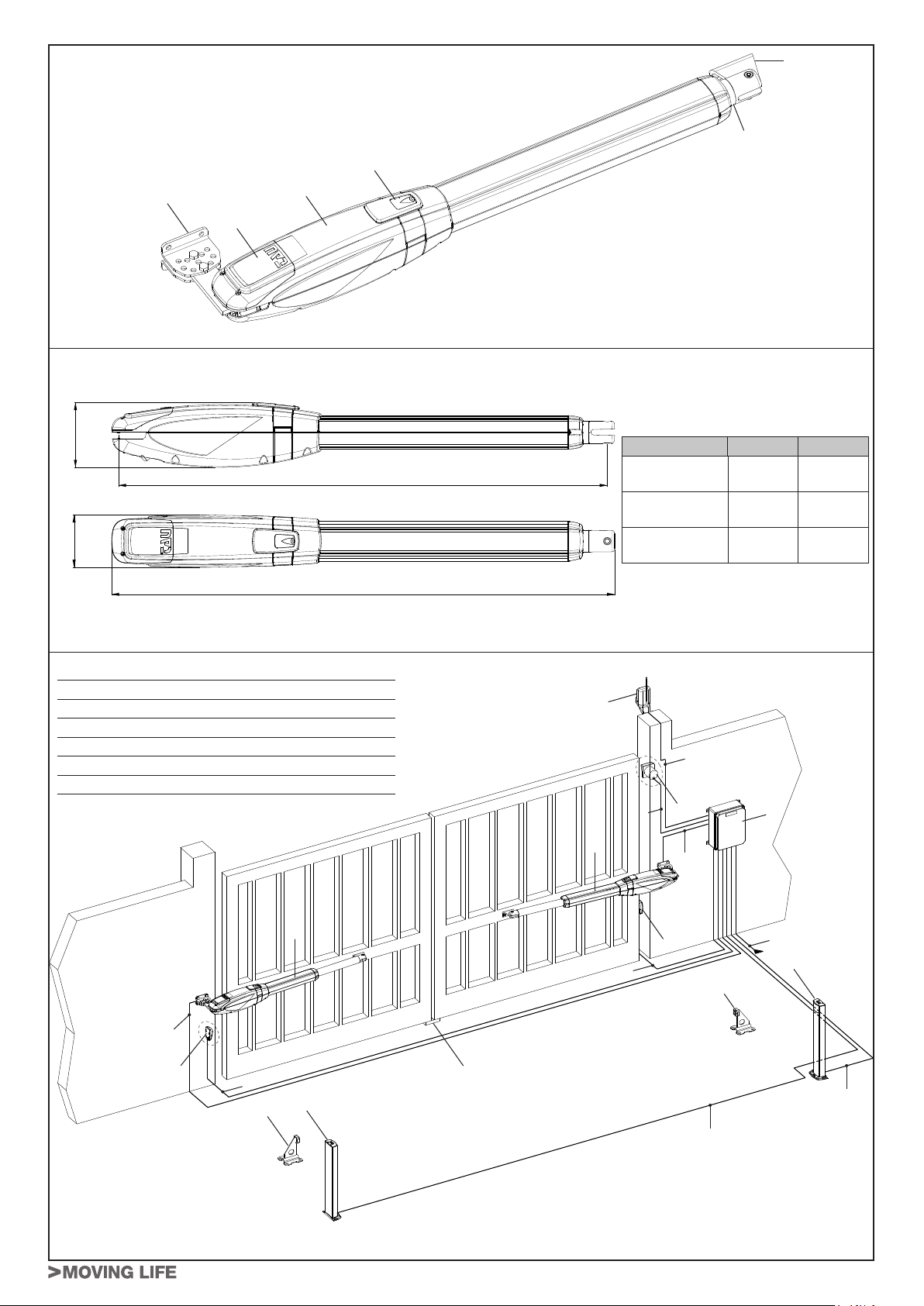
4
3
2
5
1
6
g. 1
122,5
B
99
A
ARM200 ARM200BENC
a 4x1,5 mm² 2x2,5 mm² + 3x0,5 mm²
b 3x1,5 mm² 3x1,5 mm²
c 2x0,5 mm² 2x0,5 mm²
d 4x0,5 mm² 4x0,5 mm²
e 3x0,5 mm² 3x0,5 mm²
f 2x1 mm² + 1RG58 2x1 mm² + 1RG58
g. 2
TYPE A B
ARM225 ARM225BENC
ARM250 ARM250BENC
ARM270 ARM270BENC
811 mm 783 mm
951 mm 923 mm
1056 mm 1028 mm
6
f
5
e
1
a
2
1
4
d
b
3
7
a
3
c
4
7
7
c
d
g. 3
ARM200 Series Disegni - Drawings - Zeichnen - Projets - Dibujos - Desenhos
ARM200 Series
15
- - -- - - - - - - - - - - - - - - - - - - - - - - - - - - - - - - - - - - - - - - - - - - - - - - - - - - - - - - - - - - - - - - - - - - - - - - - - - - - - - - - - - - - - - - - - - - - - -
Page 20

A
C
B
L
TYPE L
ARM225 ARM225BENC
ARM250 ARM250BENC
ARM270 ARM270BENC
1080 mm
1360 mm
1570 mm
g. 4
X°
=
=
g. 5
g. 5A
16
g. 7g. 6
1
g. 8
ARM200 Series Disegni - Drawings - Zeichnen - Projets - Dibujos - Desenhos
ARM200 Series
g. 7A
2
Page 21

1
g. 9
g. 10
g. 11 g. 12
ARM200 Series Disegni - Drawings - Zeichnen - Projets - Dibujos - Desenhos
ARM200 Series
17
Page 22

6,5 mm
g. 13
Chiude
Close
Zu
Ferme
Cierra
Fecha
Apre
Open
Auf
Ouvre
Abre
Abre
g. 14
Comune
Common
Gemeinsam
Commune
Común
Comum
Negativo motore
Motor negative
Minuspol Motor
Négatif moteur
Negativo motor
Negativo motor
Positivo motore
Motor Positive
Pluspol Motor
Positif moteur
Positivo motor
Positivo motor
Segnale encoder
Encoder signal
Encodersignal
Signal encodeur
Señal encoder
Sinal encoder
Negativo encoder
Encoder negative
Minuspol Encoder
Négatif encoder
Negativo encoder
Negativo encoder
g. 15
Positivo encoder
Encoder positive
Pluspol Encoder
Positif encoder
Positivo encoder
Positivo encoder
18
g. 16 g. 17 g. 18
ARM200 Series Disegni - Drawings - Zeichnen - Projets - Dibujos - Desenhos
ARM200 Series
- - -- - - - - - - - - - - - - - - - - - - - - - - - - - - - - - - - - - - - - - - - - - - - - - - - - - - - - - - - - - - - - - - - - - - - - - - - - - - - - - - - - - - - - - - - - - - - - -
Page 23

> ESPAÑOL
Guía
Usuario
1 2 3
5_ Efectúe la maniobra de apertura o cierre de la hoja.
Nota: Para mantener el operador en funcionamiento manual es absolutamente necesario dejar el dispositivo de desbloqueo en
la posición actual y el equipo sin alimentación.
DESBLOQUEO MANUAL
Si fuera necesario mover la automación
a mano, por ejemplo por un corte
de corriente o un fallo del operador,
proceda del siguiente modo:
1_ Quite la alimentación eléctrica por
medio del interruptor diferencial
(también en caso de corte de
corriente).
2_ Deslice el capuchón de pro-
tección, g.16;
3_ Introduzca la llave y gírela 90°,
g.17.
4_ Gire, tal como se muestra en la
g.18, la palanca de desbloqueo
hacia arriba para desbloquear el
actuador.
RESTABLECIMIENTO DEL FUNCIONAMIENTO NORMAL
Para restablecer las condiciones de funcionamiento normal proceda del siguiente modo:
1_ Cierre de nuevo la palanca de desbloqueo hacia abajo.
2_ Gire 90° la llave de desbloqueo y quítela.
3_ Cierre de nuevo la la tapa de protección.
4_ Alimente el equipo y realice algunas maniobras para comprobar que todas las funciones de la automación se han restablecido correctamente.
INSTRUCCIONES Y ADVERTENCIAS DESTINADAS AL USUARIO DE L’AUTOMATISMO
¡FELICITACIONES por haber elegido un producto TAU para su automatización!
Tau S.r.l. produce componentes para la automatización de cancelas, puertas, barreras, cerramientos, tales como: motorreductores, centrales de mando,
radiomandos, luces intermitentes, fotocélulas y accesorios.
Los productos Tau son fabricados sólo con materiales de calidad y excelentes mecanizados. Nuestra empresa busca constantemente soluciones innovadoras
que simpliquen aún más el uso de nuestros aparatos, los que son cuidados bajo todo aspecto (técnico, estético y ergonómico): en la gran gama Tau, su
instalador puede escoger el producto que satisfaga de la mejor manera sus exigencias.
Tau no es quien escoge los componentes de su automatización, este es un trabajo de análisis, evaluación, elección de los materiales y realización de la
instalación efectuado por su instalador de conanza.
Por lo tanto, cada automatización es única y sólo su instalador puede ejecutar una instalación a medida de sus exigencias (puesto que cuenta con la
experiencia y profesionalidad necesarias), segura y able en el tiempo y, sobre todo, que respete las normativas vigentes.
Una instalación de automatización es una gran comodidad, además de un sistema de seguridad válido y, con un mantenimiento reducido y sencillo, está
destinada a durar por mucho tiempo.
DESCRIPCIÓN
La automación ARM200 para cancelas de batientes es un operador electromecánico irreversible que transmite el movimiento a la hoja por medio de un sistema de
tornillo sin n.
El operador está disponible en varias versiones en 12 Vdc y 230 Vac.
El sistema irreversible garantiza el bloqueo mecánico de la hoja cuando el motor no está en funcionamiento. Un cómodo y seguro sistema de desbloqueo con llave
personalizada permite maniobrar manualmente la hoja en caso de falta de alimentación eléctrica o de avería.
Aunque bien su automatización satisfaga el nivel de seguridad requerido por las normativas, esto no excluye la existencia de un “riesgo residual”, es decir, la posibilidad
de que se puedan crear situaciones de peligro causadas por un uso inconsciente o incorrecto. Por dicho motivo, a continuación le damos algunos consejos sobre cómo
comportarse para evitar inconvenientes:
- La primera vez que se usa: pida a su instalador que le explique el origen de los riesgos residuales y lea este manual de instrucciones y advertencias para el usuario
entregado por el instalador. Conserve el manual por cualquier problema que pueda surgir y recuerde entregarlo a un posible nuevo dueño de la instalación.
- La instalación de automatización ejecuta elmente los mandos dados: un uso inconsciente o inadecuado puede ser peligroso. Por consiguiente, no accione
la automatización cuando en su radio de acción haya personas, animales o cosas.
- ¡NO ES UN JUGUETE! Trate de que los niños no jueguen cerca de la instalación y mantenga los controles remotos lejos de su alcance.
- Desperfectos: cada vez que la instalación no funcione correctamente, corte la alimentación eléctrica de la automatización y realice el desbloqueo manual (como
muestra la gura). No realice ninguna reparación y llame a su instalador: una vez desbloqueada, la instalación funcionará manualmente como antes de montar la
automatización.
- Mantenimiento: para garantizar una larga vida útil y para un funcionamiento seguro, la instalación, al igual que cualquier otra maquinaria, requiere un mantenimiento
periódico. Establezca con su instalador las frecuencias de dicho mantenimiento. Tau aconseja realizar un mantenimiento cada 6 meses para un uso residencial
normal, que puede variar según la intensidad de uso (siempre cada 3000 ciclos de trabajo).
Nota: cualquier tipo de operación (control, mantenimiento o reparación) debe ser realizada sólo por personal cualicado.
- No modique la instalación ni los parámetros de programación y regulación: la responsabilidad es del instalador.
Nota: el ensayo nal, los trabajos de mantenimiento periódico y las posibles reparaciones deben ser documentados (en los espacios disponibles) por quien
los efectúa y los documentos tienen que ser conservados por el dueño de la instalación (LA FALTA DE DOCUMENTACIÓN DETERMINA LA CADUCIDAD
DE LA GARANTÍA).
- Desguace: al nal de la vida útil de la instalación, el desguace debe ser realizado por personal cualicado y los materiales deben ser reciclados o eliminados según
las normas locales vigentes.
La maniobra manual debe efectuarse SÓLO con la puerta detenida y DESPUÉS de haber cortado la alimentación a la central eléctrica.
Nota: si su instalación está dotada de un control remoto que, transcurrido un cierto período, no funciona correctamente o deja de funcionar, podría ser que la pila esté
agotada (dura desde varios meses a 2/3 años según el modelo). Ud. se podrá dar cuenta de este inconveniente por el hecho de que la luz del indicador de conrmación
de la transmisión es débil, o bien se enciende sólo durante un breve instante. Antes de llamar al instalador, pruebe sustituir la pila con una de otro transmisor que funcione
correctamente: si el problema fuera este, sustituya la pila con otra del mismo tipo.
Si Ud. deseara montar en su casa un nuevo tipo de automatización, contacte al mismo instalador y a Tau, así podrá tener la garantía de un asesoramiento de un experto
y los productos más modernos del mercado, el mejor funcionamiento y la máxima compatibilidad de las automatizaciones.
Le agradecemos por haber leído estas recomendaciones y esperamos que esté satisfecho de su nueva instalación: ante cualquier exigencia, contacte con conanza a
su instalador.
Guida Utente - User Guide - Führer Benutzer - Guide Usager - Guía Usuario - Guia do Utilizador
5
Page 24

>
PORTUGUÊS
Guia do
Utilizador
1 2 3
4_ Como indicado na Fig. 3, rodar a patilha desembraiador para cima de modo a desbloquear o atuador.
5_ Abra ou feche a folha manualmente.
Nota: Para manter o atuador em operação manual o sistema de desbloqueio deve ser deixado na posição corrente e o sistema
não deve estar alimentado.
DESBLOQUEIO MANUAL
No caso de se tornar necessário movimentar manualmente o portão, por
falta de energia eléctrica ou problema
com a automatização, é necessário
interagir com o dispositivo de desbloqueio como se segue:
1_ Desliga a alimentação no disjun-
tor (mesmo no caso de falha de
energia).
2_ Deslize a tampa protectora, Fig.
1;
3_ Introduza a chave e rodá-la no
sentido anti-horário , Fig. 2.
REPOSIÇÃO DO FUNCIONAMENTO NORMAL
Para repôr as condições normais de operação, proceda como se segue:
1_ Bloqueie a patilha de desbloqueio empurrando para baixo.
2_ Rode a chave 90º e retire-a.
3_ Feche a tampa protectora.
4_ Ligue a alimentação e realize alguns movimentos de modo a vericar a reposição correcta de cada função da automação.
PARABÉNS por ter escolhido um produto TAU para o seu sistema de automatização.
Tau S.r.l. produz para cancelas automáticas, portões, barreiras e estores. Estes incluem o motorredutor, a unidade de controlo, rádio comandos,
pirilampos, fotocélulas e acessórios.
Os produtos Tau são feitos exclusivamente com processos e materiais de elevada qualidade e, como empresa, constantemente pesquisamos e
desenvolvemos soluções inovadoras de modo a tornar os nossos equipamentos cada vez mais fáceis de utilizar. Nós também prestamos grande
atenção a todos os detalhes (tecnologia, estética e ergonomia). A vasta gama TAU torna possível ao seu instalador escolher os productos que melhor
se adequam às vossas necessidades.
Contudo a Tau não produz a sua automatização que é, de facto, o resultado de um trabalho de análise, avaliação, escolha de materiais e da realização da instalação do vosso instalador de conança.
Cada automatização, por conseguinte, é única e só o vosso instalador pode realizar a instalação segundo as vossa exigências ( na medida em que
ele possui a experiência e competência prossional necessárias), seguro e ável ao longo do tempo e, sobretudo, efectuado prossionalmente cum-
prindo os requisitos das normas em vigor.
A instalação de um sistema automatizado é de grande conveniência além de representar um sistema de segurança. Poucas e simples operações são
necessárias para garantir que ele dure muitos anos.
A automatização ARM200 para portões de batente é um atuador electromecânico não reversível que transmite movimento à folha do portão através de
um sistema de parafuso sem m.
O atuador está disponível nas versões de 12Vdc e 230Vac.
O sistema de irreverssibilidade garante o bloqueio mecânico do portão quando o motor não está a operar , e por isso, não é necessária nemhuma
fechadura; um desbloqueio manual exterior (opcional) e interior permitem manobrar o portão em caso de falha de corrente ou avaria.
Mesmo que o seu sistema automatizado satisfaça os regulamentos padrão, isso não elimina os “riscos residuais”, que são, a possibilidade de situações
perigosas serem geradas, normalmente por irresponsabilidade ou uso incorrecto. Por esta razão gostaríamos de lhe dar algumas sugestões para evitar
esses riscos:
- Antes de utilizar o sistema pela primeira vez: pergunte ao seu instalador como os riscos residuais podem surgir e ler as instruções e avisos no
manual do utilizador que o seu instalador lhe forneceu. Guarde esse manual para uso futuro e, se alguma vez vender o seu sistema automático,
entregue-o ao novo proprietário.
- O seu sistema automático executa elmente os vossos comandos: irresponsabilidade ou uso incorrecto pode tornar-se perigoso. Evite por
isso accionar o automatismo quando pessoas, animais ou objectos se encontram no seu raio de acção.
- NÃO É UM BRINQUEDO! Certique-se quee as crianças não brincam perto do sistema e manter os rádio comandos fora do seu alcance.
- Falhas: se vericar um comportamento anormal, desligue o sistema da alimentação e proceda a abertura manual (ver gura). Não tente reparar o
seu portão chame o seu instalador: o sistema operará manualmente como o fazia antes da instalação.
- Manutenção: para assegurar uma vida longa e uma operação totalmente segura, o sistema requer uma manutenção periódica, como qualquer
outro tipo de maquinaria. Acorde com o seu instalador um plano de manutenção periódica. A Tau recomenda com uma frequêncai semestral para
instalações residenciais vulgares mas isto pode variar em função de uma maior utilização (sempre ao nal de cada 3000 ciclos).
NOTA: Todos os controlos, trabalho de manutenção ou reparações só podem ser realizadas por pessoal técnico qualicado.
- Não alterar a instalação, a programação ou ajuste de parâmetros: a responsabilidade cabe ao instalador.
NOTA: Teste nal, manutenção periódica ou qualquer reparação devem estar documentados pelo instalador ( nas folhas de controlo inspec-
ção) e tais documentos devem ser guardados pelo proprietário so sistema (SE A DOCUMENTAÇÃO NÃO FOR PRODUZIDA A GARANTIA
EXPIRARÁ).
- Classicação / Reciclagem: No nal de vida do sistema, certique-se que o desmantelamento é feito por pessoal qualicado e so materiais são
reciclados e classicados conforme normas em vigor.
A manobra manual deve ser feita SÓMENTE com o portão parado e APÒS desligar a corrente eléctrica.
INSTRUÇÕES E ALERTAS PARA UTILIZADORES DE SISTEMAS AUTOMÁTICOS
DESCRIÇÃO
Nota: Se o seu rádio comando (se fornecido) começar a funcionar mal após algum tempo, ou deixa de funcionar mesmo, as pilhas podem estar fracas (
podem durar entre 2 / 3 anos dependendo da utilização). Isto pode ser vericado de o Led de conrmação de transmissão car mais escuro ou sómente
acende por breves instantes. Antes de contactar o seu instalador , experimente trocar as pilhas de um rádio comando em boas condições: se isto é a
razão para a falha , substitua simplesmente as pilhas por novas do mesmo tipo.
Se pretender adicionar um novo sistema automático para a sua casa, contacte o seu instalador e nós na Tau temos os especialistas em aconselhamento, os produtos mais evoluídos no mercado, melhor serviço e maximo de compatibilidade de sistemas.
Obrigado por ter lido estas recomendações e nós acreditamos que cará completamente satisfeito com o seu novo sistema: por favor contacte o seu
instalador para quaisquer necessidades futuras.
6
Guida Utente - User Guide - Führer Benutzer - Guide Usager - Guía Usuario - Guia do Utilizador
Page 25

PIANO MANUTENZIONE PROGRAMMATA: Controlli semestrali
PROGRAMMED MAINTENANCE SCHEDULE: six-monthly checks
PLAN DER PROGRAMMIERTEN WARTUNGSARBEITEN: Halbjährliche Prüfungen
PLAN D’ENTRETIEN PROGRAMMÉ: Controles semestriels
PLAN DE MANTENIMIENTO PROGRAMADO: Controles semestrales
PLANO DE MANUTENÇÃO PERIÓDICA: Controlo semestral
Collegamento ed efcacia dell’interruttore
differenziale
N°
Connection and efciency of safety circuit
breaker
Taratura e corretto
funzionamento della
frizione elettronica
Setting and correct
operation of electronic
clutch
Collegamenti e funzionamento dei dispositivi di sicurezza
Connections and
operation of safety
devices
Collegamento ed
efcacia della presa
di terra
Connection and efciency of earth socket
Funzionamento del
dispositivo di sblocco
manuale
Operation of manual
release device
Funzionamento degli
eventuali necorsa
Operation of limit
switches
(if any)
DATA
DATE
DATUM
DATE
FECHA
DATA
1°
__/__/__
2°
__/__/__
3°
__/__/__
4°
Anschluss und Funktionstüchtigkeit des
Differentialschalters
Connexion et
efcacité de
l’interrupteur différentiel
Conexión y ecacia
del interruptor diferencial
Ligação e ecácia do
interruptor diferencial
Einstellung und Funktionstüchtigkeit der
elktronischen Kupplung
Etalonnage et fonctionnement correct de
l’embrayage électronique
Tarado y correcto funcionamiento del embrague electrónico
Conguração e operação correcta da embraiagem electrónica
Anschlüss und Funktionstüchtigkeit der
Sicherheitsvorrichtungen
Connexion et
fonctionnement des
dispositifs de securité
Conexión y funcionamiento de los dispositivos de seguridad
Ligações e funcionamento dos dispositivos de segurança
Anschlüss und Funktionstüchtigkeit
der Erdung
Connexion et
efcacité de
la prise de terre
Conexión y ecacia
de la toma de tierra
Ligação e ecácia da
tomada de terra
Funktionstüchtigkeit
der manuellen Freigabevorrichtung
Fonctionnement
du dispositif de
déblocage manuel
Funcionamiento del
dispositivo de desbloqueo manual
Funcionamento do
dispositivo de desbloqueio manual
Funktionstüchtigkeit
der eventuellen
endschalter
Fonctionnement
des ns de course
éventuels
Funcionamiento de
los eventuales nales
de carrera
Funcionamento dos
ns de curso
__/__/__
5°
__/__/__
6°
__/__/__
7°
__/__/__
8°
__/__/__
9°
__/__/__
10°
__/__/__
11°
__/__/__
12°
__/__/__
Guida Utente - User Guide - Führer Benutzer - Guide Usager - Guía Usuario - Guia do Utilizador
7
Page 26

PIANO MANUTENZIONE PROGRAMMATA: Controlli semestrali
PROGRAMMED MAINTENANCE SCHEDULE: six-monthly checks
PLAN DER PROGRAMMIERTEN WARTUNGSARBEITEN: Halbjährliche Prüfungen
PLAN D’ENTRETIEN PROGRAMMÉ: Controles semestriels
PLAN DE MANTENIMIENTO PROGRAMADO: Controles semestrales
PLANO DE MANUTENÇÃO PERIÓDICA: Controlo semestral
Collegamenti e funzionamento degli
accessori
N°
Connections and operation of accessories
Fissaggio dell’automatismo
Operator xing
condition
Condizioni dei
perni di ssaggio
Fastening pins
conditions
Usura dell’attacco
anteriore / posteriore
Wear of
front / rear tting
Condizioni generali
del cancello
Gate
general conditions
Firma manutentore
Firma utilizzatore
Fitter’s signature
User’s signature
DATA
DATE
DATUM
DATE
FECHA
DATA
1°
__/__/__
2°
__/__/__
3°
__/__/__
Anschlüss und Funktionstüchtigkeit der
Zubehörs
Connexion et
fonctionnement des
accessoires
Conexión y funcionamiento de los accesorios
Ligações e funcionamento dos acessórios
Befestigung des
Antrieb
Fixatuion de
l’automatisme
Fijación del accionador
Fixação do automatismo
Zustand der
Befestigungsstifte
Conditions des
axes de xation
Condiciones de los
pernos de jación
Estado dos pernos de
xação
Verschleiß des An-
schlusses vorne /
hinten
Usure de la patte
d’attache antérieure /
postérieure
Desgaste del empalme anterior / posterior
Desgaste das xações anterior e pos-
terior
Allgemeiner Zustand
des Tors
Conditions générales
du portail
Condiciones generales de la cancela
Estado geral do
portão
Unterschrift des
Wartungsmannes
Unterschrift des
Benutzers
Signature réparateur
Signature utilisateur
Firma del técnico
Firma del usuario
Assinatura
do técnico
Assinatura
do utlizador
4°
__/__/__
5°
__/__/__
6°
__/__/__
7°
__/__/__
8°
__/__/__
9°
__/__/__
10°
__/__/__
11°
__/__/__
12°
__/__/__
8
Guida Utente - User Guide - Führer Benutzer - Guide Usager - Guía Usuario - Guia do Utilizador
- - -- - - - - - - - - - - - - - - - - - - - - - - - - - - - - - - - - - - - - - - - - - - - - - - - - - - - - - - - - - - - - - - - - - - - - - - - - - - - - - - - - - - - - - - - - - - - - -
Page 27

BESCHREIBUNG
Die Automation ARM200 für Flügeltore ist ein irreversibler elektro-
mechanischer Antrieb, der über ein Schneckensystem die Bewegung auf den Flügel überträgt.
Der Antrieb ist in mehreren Versionen erhältlich in 12 Vdc und 230
Vac.
Das irreversible System gewährleistet die mechanische Verriegelung des Flügels, wenn der Motor nicht in Betrieb ist. Ein praktisches und sicheres Freigabesystem mit individuellem Schlüssel
ermöglicht die manuelle Bewegung des Flügels bei Betriebsstörungen oder Stromausfall.
ACHTUNG:
Der ordnungsgemäße Betrieb und die erklärten Daten werden nur mit Zubehör und Sicherheitsvorrichtungen der Marke TAU erreicht.
Um die notwendige Antiquetschsicherheit zu gewährleisten, muss bei Fehlen einer mechanischen
Kupplungsvorrichtung eine Steuerzentrale mit
elektronischer und einstellbarer Kupplung verwendet oder eine Schaltleiste angebracht werden.
Die Automation ARM200 wurde für die Zufahrtskontrolle von Fahrzeugen entwickelt und hergestellt,
andere Anwendungen sind zu vermeiden.
TEILE DES ANTRIEBS (Abb.1)
Pos. Beschreibung
1 Antrieb
2 Entriegelungsvorrichtung
3 Schaft
4 Toranschlussbügel
5 Hinterer Bügel
6 Abdeckung Klemmenleiste
ABMESSUNGEN (Abb.2)
INSTALLATION (Abb.3)
Elektrische Einrichtungen (Standardanlage - ARM200)
Pos. Beschreibung Kabel
1 Antrieb 4x1,5 mm²
2 Steuerzentrale
3 Photozellen TX 4x0,5 mm²
4 Photozellen RX 2x0,5 mm²
5 Schlüsselschalter 3x0,5 mm²
6 Blinklampe und Antenne 2x1 mm² + 1RG58
7 Mechanische Anschlänge -
Elektrische Einrichtungen (Standardanlage - ARM200BENC)
Pos. Beschreibung Kabel
1 Antrieb 2x2,5 mm² + 3x0,5 mm²
2 Steuerzentrale
3 Photozellen TX 4x0,5 mm²
4 Photozellen RX 2x0,5 mm²
5 Schlüsselschalter 3x0,5 mm²
6 Blinklampe und Antenne 2x1 mm² + 1RG58
7 Mechanische Anschlänge -
Anmerkungen:
• Für die Verlegung der Stromkabel sind entsprechende Rohre
und/oder Schläuche zu verwenden.
• Es sollten kurzen Strecken für die Kabel gewählt und die Leistungskabel von den Steuerkabeln getrennt gehalten werden.
Vorabprüfungen
Vor der Installation der Automatisierung alle strukturellen Änderungen für das Vorhandensein der Sicherheitsabstände und den
Schutz aller Bereiche ausführen, in denen Quetsch-, Schnitt- und
Mitnehmgefahr und Gefahren allgemein bestehen.
• Prüfen, ob die vorhandene Struktur die erforderliche Robustheit und Stabilität besitzt;
3x1,5 mm²
(versorgung)
3x1,5 mm²
(alimentazione)
ARM200 Series
• Die mechanischen Bauelemente müssen den Anforderungen
der Normen EN 12604 und EN 12605 entsprechen;
• Länge des Flügels entsprechend den Eigenschaften des Antriebs;
• gleichmäßige und reibungslose Bewegung der Flügel, ohne
Reibungen und Schleichen während der gesamten Arbeitshub;
• entsprechend robuste Scharniere in gutem Zustand;
• mechanische Anschläge beim Öffnen und beim Schließen;
• efzienter Erdungsanschluss für den elektrischen Anschluss
des Antriebs.
Eventuelle Schlosserarbeiten sollten vor der Installation der Automation ausgeführt werden.
Der Zustand der Struktur des Tors beeinusst direkt die Zuverlässigkeit und die Sicherheit der Automation.
Einbaumaße (Abb.4)
Die Montageposition des Antriebs bestimmen und hierzu Bezug
auf die Abbildung 4 nehmen.
Aufmerksam sicherstellen, dass der Abstand zwischen dem offenen Flügel und eventuellen Hindernissen (Wände, Umzäunungen
usw.) über dem Platzbedarf des Antriebs liegt.
X° A (mm) B (mm) C (mm)
90 80 ÷ 85 110 ÷ 200 20 mm
90 90 110 ÷ 195 20 mm
90 95 110 ÷ 190 20 mm
90 100 110 ÷ 185 20 mm
90 105 110 ÷ 180 20 mm
A
R
M
2
2
5
A
R
M
2
5
0
90 110 ÷ 115 110 ÷ 175 20 mm
90 120 110 ÷ 170 20 mm
90 125 110 ÷ 165 20 mm
90 130 110 ÷ 160 20 mm
90 135 110 ÷ 155 20 mm
90 140 110 ÷ 150 20 mm
90 145 ÷ 150 110 ÷ 145 20 mm
90 155 110 ÷ 140 20 mm
90 160 110 ÷ 135 20 mm
90 165 110 ÷ 130 20 mm
90 170 110 ÷ 125 20 mm
90 175 ÷ 180 110 ÷ 120 20 mm
100 100 ÷ 120 110 ÷ 150 20 mm
100 125 110 ÷ 145 20 mm
100 130 110 ÷ 140 20 mm
100 135 110 ÷ 135 20 mm
100 140 110 ÷ 130 20 mm
100 145 110 ÷ 125 20 mm
100 150 110 ÷ 120 20 mm
X° A (mm) B (mm) C (mm)
90 80 ÷ 175 115 ÷ 250 20 mm
90 180 ÷ 185 115 ÷ 245 20 mm
90 190 115 ÷ 240 20 mm
90 195 115 ÷ 235 20 mm
90 200 115 ÷ 230 20 mm
100 100 ÷ 150 115 ÷ 250 20 mm
100 155 115 ÷ 245 20 mm
100 160 115 ÷ 240 20 mm
100 165 115 ÷ 235 20 mm
100 170 115 ÷ 230 20 mm
100 175 115 ÷ 225 20 mm
100 180 115 ÷ 220 20 mm
100 185 115 ÷ 215 20 mm
100 190 115 ÷ 210 20 mm
100 195 115 ÷ 205 20 mm
100 200 115 ÷ 200 20 mm
19
DEUTSCH
Page 28

X° A (mm) B (mm) C (mm)
90 80 ÷ 235 120 ÷ 300 20 mm
A
R
M
2
7
0
Wenn das Maß “C” größer oder kleiner als 20 mm ist, muss zum Maß
“B” die Differenz addiert bzw. von diesem abgezogen werden (Beispie:
DEUTSCH
wenn C= 25mm ist, müssen zu “B” 5mm addiert werden), prüfen,
dass sich das Maß innerhalb der Grenzwerte in der Tabelle bendet.
Wenn die Abmessungen des Pfostens oder die Position des
Scharniers die Installation des Antriebs nicht ermöglichen, muss
zur Beibehaltung des bestimmten Maßes A eine Nische auf dem
Pfosten laut Angaben in Abb. 5 ausgeführt werden. Die Abmessungen der Nische müssen so beschaffen sein, dass eine problemlose Installation und Drehung des Antriebs und die Betätigung der
Freigabevorrichtung ermöglicht wird. Die Befestigungsbügel sind
so gefertigt, dass kleine Justierungen in beiden Richtungen möglich sind (Abb.5A); immer die in der Tabelle angegebenen Maße
einhalten.
Die Werte der Tabelle einhalten und Die Stützzapfen des Gittertores ölen.
1_ Den hinteren Bügel an der zuvor bestimmten Position befesti-
2_ Den Antrieb für den manuellen Betrieb einrichten (siehe Ab-
3_ Den Schaft bis zum Anschlag ganz entfernen (1 Abb.8).
4_ Den Antrieb verriegeln (siehe Abschnitt WIEDERHERSTEL-
5_ Den Schaft eine halbe Runde im Uhrzeigersinn drehen (2
6_ Den vorderen Bügel laut Angaben in Abb. 9 zusammenbauen.
7_ Den Antrieb nach der Abnahme des Klemmleistendeckels mit
8_ Das Maß “L” überprüfen, gemäß der Tabelle (Abb. 4).
9_ Den soeben befestigten Bügel auf den ganz geschlossenen
Bevor zu der nachfolgenden Arbeitsphase übergegangen wird,
sollte der folgende Versuch durchgeführt werden:
10_ Den Antrieb entriegeln (siehe Abschnitt MANUELLE ENT-
20
90 240 120 ÷ 295 20 mm
90 245 120 ÷ 290 20 mm
90 250 120 ÷ 285 20 mm
100 130 ÷ 195 120 ÷ 300 20 mm
100 200 120 ÷ 295 20 mm
100 205 120 ÷ 290 20 mm
100 210 120 ÷ 285 20 mm
100 215 120 ÷ 280 20 mm
100 220 120 ÷ 275 20 mm
100 225 120 ÷ 270 20 mm
100 230 120 ÷ 265 20 mm
100 235 120 ÷ 260 20 mm
100 240 120 ÷ 255 20 mm
100 245 120 ÷ 250 20 mm
100 250 120 ÷ 245 20 mm
gen. Bei einem Eisenpfosten nutzen Sie 4 Bohrschrauben Ø
6,3 mm (Abb. 6). Bei einem Mauerpfosten aus werk, (Abb.7),
Nr. 4 M8 Dübel verwenden (nach dem Zusammenbau, Abb.7A).
Bei der Befestigung mit einer Wasserwaage die perfekte
Nivellierung des Bügels prüfen.
HINWEIS - Bei großen Flügeln oder Toren mit kom-
pletter- bzw. teilächiger Füllung neben dem ESchloss auch die Befestigung am Pfosten verstärken (die Beschläge zusammenschweißen statt mit
Schrauben zusammenbauen, M10 statt M8 Schrauben benutzen, die Beschläge am Pfosten schwei-
ßen usw.).
schnitt MANUELLE ENTRIEGELUNG).
LUNG DES NORMALBETRIEBS).
Abb.8).
Mit Schraube und Mutter befestigen (Abb. 9).
der mitgelieferten Schraube und der entsprechenden Mutter
am hinteren Bügel befestigen (siehe 1, Abb.10);
ACHTUNG: Der Antrieb kann nur dann mit der Hand be-
wegt werden, wenn er auf dem Tor eingebaut ist und sich
in entriegelter Position bendet (siehe Abschnitt MANU-
ELLE ENTRIEGELUNG).
ACHTUNG: Sollte der Antriebskopf bei geschlossenem Tor die Halterung berühren (siehe Abb. 10), ist
die Einstellung nicht korrekt.
Torügel legen und die Befestigungsstellen markieren (die
Ebenheit beachten – siehe die Abb. 11).
RIEGELUNG) und mit der Hand sicherstellen, dass das Tor
sich vollkommen frei öffnen kann und an den mechanischen
Anschlägen zum Stillstand kommt und dass die Bewegung
des Flügels regelmäßig und reibungslos erfolgt.
ARM200 Series
11_ Die erforderlichen Korrekturarbeiten ausführen und dann die
Schritte ab Punkt 10 wiederholen.
ten maximalen Winkel von Hand öffnen;
12_ Den Arm anschrauben, bis daß sich der kleine Befestigungs-
bügel über der soeben auf dem Flügel markierten Position
bendet.
Ist dieser Vorgang möglich, ist die Installation korrekt.
Diese Methode kann auch verwendet werden, um festzulegen,
wo der kleine Befestigungsbügel für den jeweils gewünschten Öffnungswinkel (X°) angeschweißt werden soll; Bedingung ist jedoch,
daß dies möglich ist (Parameter A und B und Arbeitshub des Kolbentorantriebs müssen dies erlauben).
13_ den Anschlussbügel am Torügel in die markierte Stellung
bringen (Abb.12), dabei das Maß in Abb.13 und die Ebenheit
überprüfen.
Anmerkung: Wenn der Aufbau des Tors eine solide
Befestigung des Bügels nicht ermöglicht, müssen
Arbeiten an der Struktur vorgenommen und eine
solide Auageäche geschaffen werden.
BITTE BEMERKEN: für höchste Sicherheit ist die
Installation der mechanischen Bodenendanschläge
im Auf und Zu mit Gummistopfen Picht (7 Abb. 3),
so dass diese gleich vor den mechanischen endschaltern des kolbens eingreifen.
Das Tor bis zum gewünsch-
VERKABELUNG DES ANTRIEBS
Am unteren Teil des Antriebs bendet sich eine Klemmenleiste für
den Anschluss des Motors, der eventuellen Endschalter und die
Erdung des Antriebs. (Abb.14-15).
Die Anschlüsse des Motors und der Erdung unter Bezugnahme
auf die Abb. 14-15 und die Tabelle ausführen.
ARM200 - 230 Vac
POS. FARBE BESCHREIBUNG
1 Blau
2 Braun Phase 1
3 Schwarz Phase 2
T Gelb / Grün Erdung
Den mitgelieferten Kondensator mit den 2 Phasen des Motors parallel schalten (Klemmen Nr. 2 und Nr. 3), dabei die beiden Drähte
nicht kurzschließen, um mögliche Entladungen aufgrund von Restströmen zu vermeiden. Ausschließlich Steuerzentralen mit elektrischer Kupplung verwenden.
Sammelkontakt
ARM200BENC - 12 Vdc
POS. FARBE BESCHREIBUNG
1 Braun Pluspol Encoder
2 Blau Minuspol Encoder
3 Weiß
4 Schwarz Minuspol Motor
5 Rot Pluspol Motor
Ausschließlich Steuerungen verwenden, die mit elektrischer Kupplung ausgestattet sind.
Die Höchstlänge zwischen Steuerung und Motor darf 10 – 12 m
nicht überschreiten.
Es wird empfohlen, das von der Firma TAU srl zusammengebaute
Kabel Code M-03000010CO zu benutzen;
Positionieren Sie das Steuergerät (falls extern) in
der unmittelbaren Nähe der Motoren.
Vermeiden Sie es, die Kabel der Zusatzvorrichtungen in den Kabelkanälen zu verlegen, in denen andere Kabel vorhanden sind, die große Lasten oder
Lampen mit elektronischem Starter speisen.
Falls Tasten oder Kontrollleuchten in Wohnungen
oder Gebäuden installiert werden, die mehrere Meter vom Steuergerät entfernt sind, empfehlen wir die
Abkopplung des Signals über ein Relais, um Stö-
rungen zu vermeiden.
Encodersignal
INBETRIEBNAHME
ACHTUNG: Vor Arbeiten an der Anlage oder dem
Antrieb ist stets die Stromversorgung abzuschalten.
Page 29
Die Punkte I, J, K, L und M der ALLGEMEINEN SICHERHEITSVOR-SCHRIFTEN sind genauestens zu befolgen.
Unter Beachtung der Angaben aus Abb. 3 und die Tabelle (siehe Abschnitt INSTALLATION) die Kabelkanäle einrichten und die
elektrischen Anschlüsse des elektronischen Steuergeräts und der
ausgewählten Zubehörteile ausführen.
Es sollten kurzen Strecken für die Kabel gewählt und die Leistungskabel von den Steuerkabeln getrennt gehalten werden.
1) Die Anlage speisen und den Status der LEDS überprüfen – siehe die Anweisungen der Steuerzentrale.
2) Das elektronische Gerät je nach den eigenen Bedürfnissen
und den entsprechenden Anweisungen programmieren.
PRÜFUNG DER AUTOMATION
• Eine sorgfältige Funktionsprüfung der Automation und aller damit verbundenen Zubehörteile vornehmen, wobei besonders
auf die Sicherheitsvorrichtungen zu achten ist.
• Dem Endanwender das Heft „Führer Benutzer“ und das Wartungsmerkblatt übergeben.
• Den Benutzer korrekt über die ordnungsgemäße Betriebsweise und die Anwendung der Automation unterrichten.
• Dem Benutzer die potentiellen Gefahrenbereiche der Automa-
tion signalisieren.
MANUELLE ENTRIEGELUNG
Sollte die manuelle Bewegung der Automation erforderlich sein
aufgrund von Stromausfall oder Betriebsstörungen des Antriebs,
sind die nachfolgenden Schritte auszuführen:
1_ Mit Hilfe des Differentialschalters (auch bei Stromausfall) die
Stromversorgung unterbrechen.
2_ Die Schutzhaube - Abb.16 - gleiten lassen.
3_ Den Schlüssel einstecken und um 90° drehen, Abb.17.
4_ Den Entriegelungshebel wie in Abb. 18 gezeigt nach oben dre-
hen, um den Antrieb zu entriegeln.
5_ Den Vorgang zum Öffnen oder Schließen des Flügels manuell
ausführen.
Anmerkung: Zur Beibehaltung des manuellen Betriebs des Antriebs muss die Freigabevorrichtung
unbedingt in ihrer aktuellen Position gelassen werden und die Stromzufuhr zur Anlage muss weiterhin
unterbrochen bleiben.
WIEDERHERSTELLUNG DES NORMALBETRIEBS
Zur Wiederherstellung der normalen Betriebsbedingungen sind die
nachfolgenden Schritte auszuführen:
1_ Den Entriegelungshebel nach unten schließen.
2_ Den Freigabeschlüssel um 90° drehen und herausziehen.
3_ Den Schutzdeckel verschließen.
4_ Die Anlage mit Strom versorgen und einige Vorgänge ausfüh-
ren, um die korrekte Wiederherstellung aller Funktionen der
Automation zu prüfen.
GEBRAUCH
Die Kolbentorantriebe ARM225 - ARM225BENC, ARM250 - ARM250BENC und ARM270 - ARM270BENC wurden für die Bewegung von Flügeltoren entwickelt, deren Flügel max. 3,0 Meter, 4,0
Meter oder 5,0 Meter betragen.
Es wird ausdrücklich verboten, die Vorrichtung für andere Zwe-
cke oder unter Umständen einzusetzen, die von den genannten abweichen. Normalerweise ermöglicht die installierte elektro-
nische Steuerzentrale (die eine eingebaute elektrische Kupplung haben muss) die Wahl folgender Funktionen:
Automatisch : ein Steuerimpuls führt das Öffnen und das
Schließen des Gittertores durch.
Halbautomatisch : ein Steuerimpuls führt das Öffnen oder
das Schließen des Gittertores durch.
Bei Stromausfall kann das Tor nach Betätigung der Vorrichtung
„manuelle Entriegelung” auch von Hand funktionieren. Das über
Pufferbatterie speisbare Modell ARM200BENC ist imstande, mindestens 15 vollständige Zyklen (Öffnung und Schließung) selbständig auszuführen.
Es wird daran erinnert, dass es sich um eine automatische Vorrichtung handelt, die mit Strom gespeist wird und daher mit Vorsicht zu
verwenden ist. Im besonderen wird vor folgendem gewarnt:
• die Vorrichtung nicht mit feuchten Händen und/oder feuchten
oder nackten Füßen berühren;
• die Stromversorgung abschalten, bevor das Steuergehäuse
und/oder der Getriebemotor geöffnet werden;
• nicht am Stromkabel ziehen, um den Stecker zu ziehen;
• den Motor nicht berühren, wenn Sie sich nicht sicher sind, dass
er abgekühlt ist
• das Gittertor nur in Bewegung setzen, wenn es vollständig
sichtbar ist;
ARM200 Series
• außerhalb des Aktionsbereichs des Tors bleiben, wenn es sich
bewegt: warten, bis keine Bewegung mehr erfolgt;
• Kinder oder Tiere nicht in Tornähe spielen lassen;
• Kinder oder unfähige Personen nicht die Fernsteuerung oder
andere Vorrichtungen für die Betätigung verwenden lassen;
• eine regelmäßige Wartung ausführen;
• im Falle eines Defekts, die Stromversorgung abschalten und
das Tor, nur falls möglich uns sicher, von Hand bewegen. Keine
Eingriffe selbst ausführen, sondern sich an einen autorisierten
Techniker wenden.
WARTUNG
Damit langfristig eine ordnungsgemäße Betriebsweise und ein
konstantes Sicherheitsniveau gewährleistet werden, ist im Abstand von 6 Monaten eine allgemeine Kontrolle der Anlage vorzunehmen. Im Heft „Führer Benutzer“ ist ein Formular für die Aufzeichnung der Arbeiten enthalten.
ACHTUNG: Achtung: niemand mit Ausnahme des
Wartungsmannes, der ein Fachtechniker sein
muss, ist befugt, die Automatisierung während der
Es wird daher empfohlen, die Netzstromversorgung abzuschalten,
wodurch auch die Stromschlaggefahr vermieden wird. Falls die
Versorgung dagegen für bestimmte Überprüfungen eingeschaltet
sein muss, so sind alle Steuervorrichtungen (wie Fernbedienungen, Druckknopftafeln, usw.) mit Ausnahme der vom Wartungsmann benutzten Vorrichtung zu deaktivieren.
Die Antriebe ARM200 / ARM200BENC erfordern wenig Wartung;
ihr guter Betrieb hängt auch von dem Zustand des Tors ab: aus
diesem Grunde beschreiben wir kurz auch die Tätigkeiten, die
durchzuführen sind, um das Tor immer leistungsfähig zu halten.
Gewöhnliche Wartung
Jede der folgenden Arbeiten muss wenn nötig und mindestens alle
6 Monate für den normalen Hausgebrauch (ungefähr 3000 Arbeitszyclen) und alle 2 Monate für den intensiven Gebrauch z. B. Wohnblockbetrieb (immer ungefähr 3000 Arbeitszyklen).
Tor:
- die Angelzapfen des Tors schmieren und einfetten.
Automatisierungsanlage:
- Den einwandfreien Betrieb der Sicherheitsvorrichtungen (Pho-
- Die vom unteren Teil des Antriebs aus erreichbare Schnecke
- Den Ladestand der Batterie mit einem Testgerät für Blei-
Außergewöhnliche Wartung oder wichtige Störungen
Falls schwierigere Arbeiten an elektromechanischen Teilen erforderlich sein sollten, wird die Entfernung des defekten Teils empfohlen, damit eine Reparatur in der Werkstatt durch die Herstellertechniker oder autorisierte Techniker erfolgen kann.
Wir empfehlen, alle Unterlagen der Anlage in der Steuerzentrale oder in ihrer unmittelbaren Nähe aufzubewahren.
Wartung zu steuern.
ACHTUNG: Falls die Installation in Gebieten erfolgt,
die einen hohen Gehalt von Salz oder Sand in der
Luft aufweisen (Meeresnähe, Wüstengebiete usw.),
muss die Wartung häuger vorgenommen werden
(alls zwei bis drei Monate).
tozellen, Sicherheitsleiste, etc.) in Zeiten und auf die Weisen
überprüfen, die von den Herstellern vorgeschrieben werden;
einfetten (mit Fettbüchse, siehe Abb.12); der Gebrauch von
SYNECO Lithiumseifenfett wird empfohlen.
Säure-Batterien überprüfen; im Falle eines Austausches eine
Originalbatterie verwenden und die leere Einheit gemäß der
gültigen Vorschriften entsorgen (anstelle der Originalbatterie
empehlt die Firma TAU den Gebrauch von FIAMM Batterien).
BITTE BEMERKEN: Im Laufe der Zeit kann sich eine
dünne Rostlinie auf dem Schaft des Antriebs bilden. Dies ist auf die Hinzufügung von Material beim
Schweißen des Rohrs/Schaftes zurückzuführen
und beeinträchtigt keinesfalls weder die Qualität
des Schaftes noch den normalen Betrieb des Getriebemotors. Es wird empfohlen, den Schaft periodisch mit speziellen Edelstahlreinigern zu reinigen.
SPEZIELLE ANWENDUNGEN
Neben der beschriebenen sachgemäßen Anwendung sind keine
weiteren Anwendungen vorgesehen.
GERÄUSCH
Das durch den Toröffner gebildete Geräusch ist unter normalen
Betriebsbedingungen konstant und überschreitet 70 dB nicht.
21
DEUTSCH
Page 30

INTEGRIERUNGSERKLÄRUNG DES HERSTELLERS
(gemäß der Europäischen Richtlinie 2006/42/EG Anl. II.B)
Hersteller: TAU S.r.l.
Adresse: Via E. Fermi, 43
36066 Sandrigo (Vi)
ITA LY
Erklärt unter seiner Haftung, dass das Produkt: Elektromechanischer Antrieb
für die automatische Bewegung von: Drehtore
für eine Anwendung: Privat / Gewerbe
Einschließlich: -
DEUTSCH
Modell: ARM200
Typ: ARM225 / ARM225BENC / ARM250 / ARM250BENC
ARM270 / ARM270BENC
Seriennummer: SIEHE SILBERETIKETTE
Handelsbezeichnung: DREHTORANTRIEB FÜR PRIVAT UND GEWERBE
ausgeführt wurde, um in einen Verschluss integriert zu werden (Drehtore) oder um mit anderen Vorrichtungen kombiniert zu werden,
um diesen Verschluss zu bewegen, und somit gemäß der Maschinenrichtlinie 2006/42/EG eine Maschine darstellt.
Außerdem erklärt er, dass dieses Produkt den grundsätzlichen Sicherheitseigenschaften der folgenden Richtlinien EWG entspricht:
- 2006/95/EG Niederspannungsrichtlinie
- 2004/108/EG Richtlinie für elektromagnetische Kompatibilität
Und wo gefordert, der Richtlinie:
- 1999/5/CE Radio equipment and telecommunications terminal equipment
Außerdem wird erklärt, dass es nicht zugelassen ist, die Vorrichtung in Betrieb zu setzen, bis die Maschine, in die sie integriert wird
oder deren Bestandteil sie sein wird, identiziert und die Konformität gegenüber dem Inhalt der Richtlinie 2006/42/EG erklärt wurde.
Er verpichtet sich, auf ausdrücklichen Wunsch der nationalen Behörden, Informationen über die Fastmaschinen zu übersenden.
Sandrigo, 31/03/2010
Der gesetzliche Vertreter
_________________________________________
Bruno Danieli
Name und Adresse der beauftragten Person zur Vorlegung der zugehörigen technischen Unterlagen:
Loris Virgilio Danieli - via E. Fermi, 43 - 36066 Sandrigo (Vi) Italy
22
ARM200 Series
Page 31
DESCRIPTION
L’automatisme ARM200 pour portails battants est un opérateur
électromécanique irréversible qui transmet le mouvement au vantail par l’intermédiaire d’un système à vis sans n.
L’opérateur est disponible en plusieurs versions en 12 Vdc et 230
Vac.
Le système irréversible garantit le verrouillage mécanique du vantail quand le moteur n’est pas en fonction. Un système pratique et
sûr de déblocage à clé personnalisée permet l’actionnement manuel du vantail en cas de dysfonctionnement ou de coupure de
courant.
ATTENTION:
Le fonctionnement correct et les caractéristiques
déclarées n’est possible qu’avec les accessoires et
les dispositifs de sécurité TAU.
L’absence de dispositif d’embrayage mécanique
demande, pour garantir la sécurité anti-écrasement
nécessaire, l’emploi d’une logique de commande
avec embrayage électronique réglable ou l’application d’un bord sensible.
L’automatisme ARM200 a été conçu et construit
pour contrôler l’accès de véhicules; éviter toute
autre utilisation.
• Vérier que la structure existante possède la robustesse et la
stabilité nécessaires;
• les composants mécaniques doivent répondre aux prescriptions des Normes EN 12604 et EN 12605;
• longueur du vantail conforme avec les caractéristiques de
l’opérateur;
• mouvement régulier et uniforme des vantaux, sans frottements
ni blocage pendant toute la course;
• charnières sufsamment robustes et en bon état;
• présence des butées mécaniques de n de course en ouverture et en fermeture;
• existence d’une prise de terre pour la connexion électrique de
l’opérateur.
On recommande d’effectuer les interventions de forge avant d’installer l’automatisme.
L’état de la structure du portail inuence directement la abilité et la sécurité de l’automatisme.
Cotes d’installation (g.4)
Déterminer la position de montage de l’opérateur en se reportant
à la g.4.
Vérier attentivement que la distance entre le vantail ouvert et les
obstacles éventuels (murs, clôtures etc.) est supérieure à l’encombrement de l’opérateur
ÉLÉMENTS DU VÉRIN (g.1)
Pos. Description
1 Opérateur
2 Dispositif de déblocage
3 Tige
4 Patte de xation porte
5 Patte postérieure
6 Couvercle bornier
DIMENSIONS (g.2)
INSTALLATION (g.3)
Prédispositions électriques (installation standard - ARM200)
Pos. Description Câbles
1 Opérateur 4x1,5 mm²
2 Logique de commande
3 Photocellules TX 4x0,5 mm²
4 Photocellules RX 2x0,5 mm²
5 Sélecteur à clé 3x0,5 mm²
6 Clignotant et antenne 2x1 mm² + 1RG58
7 Arrêts mécaniques -
Prédispositions électriques (installation standard - ARM200BENC)
Pos. Description Câbles
1 Opérateur 2x2,5 mm² + 3x0,5 mm²
2 Logique de commande
3 Photocellules TX 4x0,5 mm²
4 Photocellules RX 2x0,5 mm²
5 Sélecteur à clé 3x0,5 mm²
6 Clignotant et antenne 2x1 mm² + 1RG58
7 Arrêts mécaniques -
Remarques:
• Utiliser des tubes rigides et/ou exibles pour la pose des câbles
électriques.
• Choisir des parcours brefs pour les câbles et séparer les câbles
de puissance des câbles de commande.
Vérications préliminaires
Avant d’installer l’automatisme, apporter toutes les modications
structurelles relatives à la réalisation des espaces de sécurité et
à la protection ou à l’isolement de toutes les zones d’écrasement,
cisaillement et de danger en général.
3x1,5 mm²
(alimentation)
3x1,5 mm²
(alimentation)
ARM200 Series
A
R
M
2
2
5
A
R
M
2
5
0
X° A (mm) B (mm) C (mm)
90 80 ÷ 85 110 ÷ 200 20 mm
90 90 110 ÷ 195 20 mm
90 95 110 ÷ 190 20 mm
90 100 110 ÷ 185 20 mm
90 105 110 ÷ 180 20 mm
90 110 ÷ 115 110 ÷ 175 20 mm
90 120 110 ÷ 170 20 mm
90 125 110 ÷ 165 20 mm
90 130 110 ÷ 160 20 mm
90 135 110 ÷ 155 20 mm
90 140 110 ÷ 150 20 mm
90 145 ÷ 150 110 ÷ 145 20 mm
90 155 110 ÷ 140 20 mm
90 160 110 ÷ 135 20 mm
90 165 110 ÷ 130 20 mm
90 170 110 ÷ 125 20 mm
90 175 ÷ 180 110 ÷ 120 20 mm
100 100 ÷ 120 110 ÷ 150 20 mm
100 125 110 ÷ 145 20 mm
100 130 110 ÷ 140 20 mm
100 135 110 ÷ 135 20 mm
100 140 110 ÷ 130 20 mm
100 145 110 ÷ 125 20 mm
100 150 110 ÷ 120 20 mm
X° A (mm) B (mm) C (mm)
90 80 ÷ 175 115 ÷ 250 20 mm
90 180 ÷ 185 115 ÷ 245 20 mm
90 190 115 ÷ 240 20 mm
90 195 115 ÷ 235 20 mm
90 200 115 ÷ 230 20 mm
100 100 ÷ 150 115 ÷ 250 20 mm
100 155 115 ÷ 245 20 mm
100 160 115 ÷ 240 20 mm
100 165 115 ÷ 235 20 mm
100 170 115 ÷ 230 20 mm
100 175 115 ÷ 225 20 mm
100 180 115 ÷ 220 20 mm
100 185 115 ÷ 215 20 mm
100 190 115 ÷ 210 20 mm
100 195 115 ÷ 205 20 mm
100 200 115 ÷ 200 20 mm
FRANCAIS
23
Page 32

X° A (mm) B (mm) C (mm)
90 80 ÷ 235 120 ÷ 300 20 mm
A
R
M
2
7
0
Quando la mesure « C » résulte être supérieure/inférieure à 20
mm, augmenter/diminuer la mesure « B » de la différence (ex. : si
C= 25 mm, augmenter « B » de 5 mm), en vériant qu’elle rentre
dans les limites indiquées dans le tableau.
Si les dimensions du pilier ou la position de la charnière ne permettent pas l’installation de l’opérateur, pour maintenir la cote A donnée, il sera nécessaire de réaliser une niche sur le pilier d’après la
Fig.5. Les dimensions de la niche doivent permettre une installation facile, la rotation de l’opérateur et l’actionnement du dispositif
de déblocage. Les étriers de xation sont conçus pour fournir des
FRANCAIS
petits ajustements dans les deux directions (g. 5A) ; dans tous les
cas respecter toujours les mesures gurant dans le tableau.
Respecter les valeurs du tableau et huiler les gonds du portail.
1_ Fixer la patte postérieure dans la position déterminée précé-
2_ Prédisposer l’opérateur pour le fonctionnement manuel (voir
3_ Extraire complètement la tige jusqu’à la butée (1 g. 8).
4_ Bloquer de nouveau l’opérateur (voir par. RÉTABLISSEMENT
5_ Tourner d’un demi-tour la tige en sens horaire (2 g. 8).
6_ Assembler la patte antérieure d’après la g. 9. Fixer la vis avec
7_ Après avoir enlevé le couvercle du bornier, xer le vérin à
8_ Vérier la mesure « L » conformément au tableau (g. 4).
9_ Appuyer l’étrier que l’on vient de xer contre le vantail du por-
Avant de passer à la phase successive, effectuer l’essai suivant:
10_ Débloquer l’opérateur (voir par. DÉBLOCAGE MANUEL) et
11_ Effectuer les interventions correctives nécessaires et recom-
24
90 240 120 ÷ 295 20 mm
90 245 120 ÷ 290 20 mm
90 250 120 ÷ 285 20 mm
100 130 ÷ 195 120 ÷ 300 20 mm
100 200 120 ÷ 295 20 mm
100 205 120 ÷ 290 20 mm
100 210 120 ÷ 285 20 mm
100 215 120 ÷ 280 20 mm
100 220 120 ÷ 275 20 mm
100 225 120 ÷ 270 20 mm
100 230 120 ÷ 265 20 mm
100 235 120 ÷ 260 20 mm
100 240 120 ÷ 255 20 mm
100 245 120 ÷ 250 20 mm
100 250 120 ÷ 245 20 mm
demment. Si le pilier est en fer, utiliser n°4 vis autotaradeuses
Ø 6,3 mm (g. 6). Si le pilier est en maçonnerie (g. 7), utiliser
n°4 chevilles M10 (après l’avoir assemblée, g. 7A).
Durant les opérations de xation, vérier avec un niveau à
bulle que la patte est parfaitement horizontale.
Note: en présence de grand portails ou bien de
portails à vantaux pleins, nous recommandons de
prévoir l’installation d’une serrure électrique, soit
pour garder la fermeture bien serrée soit pour la
protection du produit. En outre, renforcer la xation
de la patte postérieure (souder la patte au lieu de
l’assembler avec des vis, utiliser des vis M10 au lieu
de M8, souder directement la patte au pilier, etc.).
par. DÉBLOCAGE MANUEL).
DU FONCTIONNEMENT NORMAL).
son écrou (g. 9).
l’étrier arrière avec la vis et l’écrou fourni (voir 1 g. 10) ;
ATTENTION: on peut actionner l’opérateur manuellement
uniquement et exclusivement s’il est installé sur le portail et en position débloquée (voir par. DÉBLOCAGE MANUEL).
ATTENTION: avec le ventail fermé, il faut contrôler
que le bout du vérin ne touche pas la plaque de xation arrière (g. 10) et dans l’éventualité modier le
réglage.
tail complètement fermé et marquer les points de xation (en
veillant à la planéité, voir g. 11).
vérier manuellement que le portail est libre de s’ouvrir complètement en s’arrêtant sur les arrêts mécaniques de n de
course et que le mouvement du vantail est régulier et sans
frottements.
mencer à partir du point 10.
jusqu’à l’angle maximum désiré
Ouvrir manuellement le portail
;
ARM200 Series
12_ Visser le bras jusqu’à ce que la petite patte puisse se super-
poser à la position marquée sur le battant.
Si l’opération est possible, l’installation est correcte.
On peut utiliser cette méthode pour calculer où souder la petite
patte pour chaque angle d’ouverture (X°) désiré à condition que
cela soit possible (si les paramètres A et B et la course utile de
l’actionneur le permettent).
13_ xer l’étrier de xation du vantail dans la position marquée
(g.12) en vériant la mesure de la g.13, et en veillant à la
planéité.
Note: si la structure du portail ne permet pas une
xation solide de la patte, intervenir sur la structure
du portail en réalisant une base d’appui solide.
Note : pour une sécurité complète, il est obligatoire
d’installer, s’il n’y en a pas, les arrêts mécaniques
(butées au sol) avec bouchon en caoutchouc en
ouverture et fermeture (7 g. 3), de manière qu’elles
interviennent juste avant les ns de course méca-
niques du piston.
CÂBLAGE DE L’OPÉRATEUR
Dans la partie inférieure de l’opérateur se trouve un bornier pour la
connexion du moteur, des ns de course éventuels et pour la mise
à la terre de l’opérateur. (gg.14-15).
Réaliser les connexions du moteur et de la mise à la terre en se
reportant à la gg.14-15 et au tableau.
ARM200 - 230 Vac
POS. COLEUR DESCRIPTION
1 Bleu
2 Marron Phase 1
3 Noir Phase 2
T Jaune / Vert Mise à la terre
Connecter le condenseur en parallèle aux deux phases du moteur
(bornes n° 2 et n° 3) en veillant à ne pas court-circuiter les deux
ls an d’éviter tout risque de décharge due à des courants résiduels. N’utiliser que des logiques de commande avec embrayage
électrique.
Commun
ARM200BENC - 12 Vdc
POS. COLEUR DESCRIPTION
1 Marron Positif encodeur
2 Bleu Négatif encodeur
3 Blanc
4 Noir Négatif moteur
5 Rouge Positif moteur
Utiliser esxclusivement des logiques de commande munies d’embrayage électrique.
La distance maximale entre l’unité et le moteur ne doit pas dépas-
ser 10 - 12 m.
Nous conseillons d’utiliser le cable composé TAU srl, code M-
03000010CO.
Placer la centrale de commande (si externe) le plus
proche aux moteurs.
Il faut éviter que les câbles des appareils auxiliaires
sont positionnés dans les canalisation où il y a
d’autres câbles qui alimentent les charges importantes ou les lampes par starter électronique.
Au cas où il faut installer des boutons de commande ou de voyants de signalisation dans les maisons ou les bâtiments qui sont situés à quelques
mètres de la centrale de commande, il est conseillé
de découpler le signal au moyen de relais pour évi-
ter les bruits induits.
Signal encodeur
MISE EN FONCTION
ATTENTION: Couper le courant avant toute intervention sur l’installation ou sur l’opérateur.
Page 33

Suivre scrupuleusement les points I, J, K, L et M des OBLIGATIONS GENERALES DE SECURITE.
En suivant les indications de la g.3 et de la tableau (voir par.
INSTALLATION), prédisposer les canalisations et réaliser les
connexions électriques de l’armoire électronique et des accessoires choisis.
Choisir des parcours brefs pour les câbles et séparer les câbles de
puissance des câbles de commande.
1) Alimenter le système et vérier l’état des leds conformément
aux instructions de la logique de commande.
2) Programmer l’armoire électronique suivant les exigences
propres d’après les instructions.
ESSAI DE L’AUTOMATISME
• Procéder à la vérication fonctionnelle et minutieuse de l’automatisme et de tous les accessoires connectés, en faisant particulièrement attention aux dispositifs de sécurité.
• Remettre à l’utilisateur nal le livret «Guide Usager» ainsi que
la che d’Entretien.
• Illustrer et instruire correctement l’utilisateur sur le fonctionne-
ment et l’utilisation de l’automatisme.
• Signaler à l’utilisateur les zones de danger potentiel de l’automatisme.
DÉBLOCAGE MANUEL
Si nécessaire, actionner manuellement l’automatisme; en cas de
coupure de courant ou de dysfonctionnement de l’opérateur, agir
comme suit:
1_ Couper le courant en agissant sur l’interrupteur différentiel
(même si le courant est déjà coupé).
2_ Faire coulisser le capuchon de protection, g.16;
3_ Introduire la clé et la tourner de 90°, g.17.
4_ Tourner le levier de débrayage vers le haut, comme indiqué sur
la g.18, pour débrayer le vérin.
5_ Effectuer manuellement la manœuvre d’ouverture ou de ferme-
ture du vantail.
Note: pour maintenir l’opérateur en fonctionnement
manuel, il est absolument nécessaire de laisser le
dispositif de déblocage dans la position actuelle et
l’installation hors tension.
RÉTABLISSEMENT DU FONCTIONNEMENT NORMAL
Pour rétablir les conditions de fonctionnement normal, agir comme
suit:
1_ Refermer le levier de débrayage vers le bas.
2_ Tourner de 90° la clé de déblocage et l’extraire.
3_ Refermer le couvercle de protection.
4_ Alimenter l’installation et effectuer quelques manœuvres pour
vérier le rétablissement de toutes les fonctions de l’automa-
tisme.
EMPLOI
Les actionneurs ARM225 - ARM225BENC, ARM250 - ARM250BENC et ARM270 - ARM270BENC ont été projetés pour ouvrir
et fermer des portails avec battant maximum respectif de 3.0, 4.0
et 5.0 m.
Il est formellement interdit d’utiliser l’appareil pour des buts
différents ou dans des circonstances différentes de celles qui
sont mentionnées ici. Normalement, la logique électronique ins-
tallée (qui doit avoir l’embrayage électrique incorporé) permet
de sélectionner le fonctionnement:
automatique : une impulsion de commande effectue l’ouverture et
la fermeture du portail;
semi-automatique : une impulsion de commande effectue l’ouverture ou la fermeture du portail;
En cas de coupure de courant électrique, le portal peut fonctionner grâce à la possibilité de gestion manuelle, pour laquelle
il faut agir sur le dispositif de “débrayage manuel”. Les modèles
ARM200BENC, alimentables par batterie tampon, sont en mesure
d’effectuer au moins 15 cycles complets (ouverture et fermeture)
de manière autonome.
Nous rappelons que nous sommes en présence d’un dispositif automatique alimenté par le courant électrique; il faut donc prendre
toutes les précautions de rigueur. En particulier, faire attention à:
• ne pas toucher l’appareil avec les mains mouillées et/ou avec
les pieds mouillés ou nus;
• couper le courant avant d’ouvrir le boîtier des commandes et/
ou l’actionneur;
• ne pas tirer le cordon d’alimentation pour débrancher la prise
de courant;
• ne pas toucher le moteur si l’on n’est pas sûr qu’il est refroidi
• mettre en mouvement le portail seulement quand il est complètement visible;
• rester hors du rayon d’action du portail tant qu’il est en mouvement: attendre qu’il soit complètement arrêté;
ARM200 Series
• ne pas laisser les enfants ou les animaux jouer à proximité du
portail;
• ne pas laisser des enfants ou des incapables manipuler la télécommande ou d’autres dispositifs d’actionnement;
• effectuer la maintenance périodique;
• en cas de panne, couper l’alimentation, ouvrir et fermer manuellement le portail seulement si cette opération est possible
et sûre. Eviter toute intervention et faire appel à un technicien
agréé.
ENTRETIEN
Pour assurer dans le temps un fonctionnement correct et un niveau de sécurité constant, effectuer tous les six mois un contrôle
général de l’installation. Dans le livret «Guide Usager» se trouve
un formulaire pour l’enregistrement des interventions.
ATTENTION : personne, à l’exception de la personne chargée de la maintenance qui doit être un
technicien spécialisé, doit pouvoir commander l’automatisme pendant la maintenance.
Nous recommandons par conséquent de couper l’alimentation de
secteur, évitant ainsi le risque de chocs électriques. Si par contre
l’alimentation doit être présente pour certains contrôles, nous recommandons de contrôler ou de désactiver tout dispositif de commande (émetteurs, tableaux de commande, etc.) à l’exception de
celui qui est commandé par la personne chargée de la mainte-
nance.
Les actionneurs ARM2000 et ARM2000BENC ont besoin de peu
d’entretien. Toutefois, leur bon fonctionnement dépend également
de l’état du portail; par conséquent, nous décrirons brièvement
également les opérations à accomplir pour avoir toujours un portail en bon état.
Entretien ordinaire
Chacune des opérations suivantes doit être effectuée tous les 6
mois pour un usage domestique (environ 3000 cycles de travail)
et tous les 2 mois pour un usage intensif, par ex. usage collectif
(toujours tous les 3000 cycles de travail).
ATTENTION : Si l’installation est effectuée dans des
régions riche en salinité et/ou en sable (zones maritimes, zones désertiques, etc.) l’entretien doit être
plus fréquent, tous les 2/3 mois.
Portail :
- lubrier et graisser les gonds du portail.
Automatisme :
- vérication du fonctionnement des dispositifs de sécurité (cellules photoélectriques, barre palpeuse etc.) en respectant
les fréquences et en suivant les modalités indiquées par les
constructeurs;
- graisser (avec un graisseur) la vis sans n accessible par la
partie inférieure du vérin (voir g.12); nous conseillons d’utiliser de la graisse au savon de lithium complexe de la marque
SYNECO.
- vérier l’état de charge de la batterie avec un testeur pour batteries au plomb-acide; en cas de remplacement, utiliser une
batterie originale et recycler l’unité déchargée selon la réglementation en vigueur (en alternative TAU conseille d’utiliser
des batteries FIAMM).
Note : avec le temps, il peut se former une ne
rayure d’oxyde sur la tige du vérin. Ce phénomène
est lié à l’apport de matériau pour la soudure du
tube/tige et NE COMPROMET ABSOLUMENT PAS ni
la qualité de la tige en question ni le fonctionnement
normal de l’opérateur. Il est conseillé de nettoyer
périodiquement la tige avec des produits spéciaux
pour l’acier inox.
Entretien extraordinaires et rupture
Si des interventions d’une certaine entité devaient se rendre
nécessaire sur des parties électromécaniques, nous conseillons
d’enlever le composant concerné par la panne pour permettre
une réparation en atelier par les techniciens de la maison mère ou
agréés par cette dernière.
Nous conseillons de conserver toute la documentation relative à l’installation à l’intérieur de l’armoire de commande ou
à proximité immédiate.
APPLICATIONS PARTICULIÈRES
On n’a prévu aucune application différente de celle qui est décrite.
NIVEAU SONORE
Le bruit aérien produit par l’opérateur dans des conditions normales d’utilisation est constant et ne dépasse pas 70 dB.
25
FRANCAIS
Page 34

DÉCLARATION D’INCORPORATION DU FABRICANT
(conformément à la Directive européenne 2006/42/CE Annexe II.B)
Fabricant : TAU S.r.l.
Adresse : Via E. Fermi, 43
36066 Sandrigo (Vi)
ITA LY
Déclare sous sa propre responsabilité que le produit : Vérin électromécanique
réalisé pour le mouvement automatique de : Portails à Battant
pour l’utilisation en milieu : Résidentiel / Intensif
muni de : -
Modèle : ARM200
Type : ARM225 / ARM225BENC / ARM250 / ARM250BENC
FRANCAIS
Numéro de série : VOIR ÉTIQUETTE ARGENTÉE
Appellation commerciale : AUTOMATISME POUR PORTAILS À BATTANT
est réalisé pour être incorporé sur une fermeture (portail à battant) ou pour être assemblé avec d’autres dispositifs an de manœuvrer
cette fermeture pour constituer une machine au sens de la Directive Machines 2006/42/CE.
Déclare d’autre part que ce produit est conforme aux exigences essentielles de sécurité des directives CEE suivantes :
- 2006/95/CE Directive Basse Tension
- 2004/108/CE Directive Compatibilité Électromagnétique
et, si requis, à la Directive:
- 1999/5/CE Équipements hertziens et équipements terminaux de télécommunication
Le Fabricant déclare également qu’il n’est pas permis de mettre en service l’appareil tant que la machine dans laquelle il sera incorporé ou dont il deviendra composant n’a pas été identiée et que sa conformité aux conditions de la Directive 2006/42/CE n’a pas
été déclarée.
ARM270 / ARM270BENC
Il s’engage à transmettre, sur demande dûment motivée des autorités nationales, des informations pertinentes sur les quasi-machines.
Sandrigo, 31/03/2010
Le Représentant légal
_________________________________________
Bruno Danieli
Nom et adresse de la personne autorisée à constituer la documentation technique pertinente :
Loris Virgilio Danieli - via E. Fermi, 43 - 36066 Sandrigo (Vi) Italy
26
ARM200 Series
Page 35

DESCRIPCIÓN
La automación ARM200 para cancelas de batientes es un opera-
dor electromecánico irreversible que transmite el movimiento a la
hoja por medio de un sistema de tornillo sin n.
El operador está disponible en varias versiones en 12 Vdc y 230
Vac.
El sistema irreversible garantiza el bloqueo mecánico de la hoja
cuando el motor no está en funcionamiento. Un cómodo y seguro
sistema de desbloqueo con llave personalizada permite maniobrar
manualmente la hoja en caso de falta de alimentación eléctrica o
de avería.
ATENCIÓN:
El correcto funcionamiento y las características
declaradas sólo se obtienen con los accesorios y
dispositivos de seguridad TAU.
Cuando no se dispone de un dispositivo de fricción
mecánica, para poder garantizar la seguridad antiaplastamiento necesaria, se tendrá que utilizar una
central de mando con fricción electrónica regulable
o aplicar un borde sensible.
La automación ARM200 ha sido proyectada y fabricada para controlar el acceso de vehículos, evítese
cualquier otra utilización.
• Controle que la estructura existente posea los criterios necesarios de robustez y estabilidad;
• Los elementos constructivos mecánicos deben estar de acuerdo con lo establecido en las Normas EN 12604 y EN 12605;
• Longitud de la hoja conforme con las características del operador;
• Movimiento regular y uniforme de las hojas, sin rozamientos ni
tropiezos durante toda la carrera;
• Buen estado y adecuada robustez de las bisagras;
• Presencia de los topes mecánicos de nal de carrera tanto en
apertura como en cierre;
• Presencia de una eciente toma de tierra para la conexión
eléctrica del operador.
Se aconseja efectuar las posibles intervenciones de fábrica antes
de instalar la automación.
El estado de la estructura de la cancela inuye directamente
en la abilidad y seguridad de la automación.
Cotas de instalación (g.4)
Establezca la posición de montaje del operador tomando como
referencia la g.4.
Compruebe atentamente que la distancia entre la hoja abierta y
los posibles obstáculos (paredes, vallas, etc.) sea superior al es-
pacio ocupado por el operador
ELEMENTOS DEL ACTUADOR (g.1)
Pos. Descripción
1 Actuador
2 Dispositivo de desbloqueo
3 Vástago
4 Brida de jación de la hoja
5 Brida posterior
6 Tapa regleta de bornes
DIMENSIONES (g.2)
INSTALACIÓN (g.3)
Predisposiciones eléctricas (equipo estándar - ARM200)
Pos. Descripción Cables
1 Actuador 4x1,5 mm²
2 Panel de mando
3 Fotocélulas TX 4x0,5 mm²
4 Fotocélulas RX 2x0,5 mm²
5 Selector de llave 3x0,5 mm²
6 Luz intermitente y antena 2x1 mm² + 1RG58
7 Bloqueos mecánicos -
Predisposiciones eléctricas (equipo estándar - ARM200BENC)
Pos. Descripción Cables
1 Actuador 2x2,5 mm² + 3x0,5 mm²
2 Panel de mando
3 Fotocélulas TX 4x0,5 mm²
4 Fotocélulas RX 2x0,5 mm²
5 Selector de llave 3x0,5 mm²
6 Luz intermitente y antena 2x1 mm² + 1RG58
7 Bloqueos mecánicos -
Notas:
• Para tender los cables eléctricos, utilice tubos rígidos y/o exibles adecuados.
• Elija recorridos breves para los cables y mantenga separados
los cables de potencia de aquellos de mando.
Comprobaciones previas
Antes de instalar la automatización, realice todas las modicaciones estructurales relativas a la realización de las distancias de
seguridad y a la protección o separación de todas las zonas de
aplastamiento, corte y peligro en general.
3x1,5 mm²
(alimentación)
3x1,5 mm²
(alimentación)
ARM200 Series
A
R
M
2
2
5
A
R
M
2
5
0
X° A (mm) B (mm) C (mm)
90 80 ÷ 85 110 ÷ 200 20 mm
90 90 110 ÷ 195 20 mm
90 95 110 ÷ 190 20 mm
90 100 110 ÷ 185 20 mm
90 105 110 ÷ 180 20 mm
90 110 ÷ 115 110 ÷ 175 20 mm
90 120 110 ÷ 170 20 mm
90 125 110 ÷ 165 20 mm
90 130 110 ÷ 160 20 mm
90 135 110 ÷ 155 20 mm
90 140 110 ÷ 150 20 mm
90 145 ÷ 150 110 ÷ 145 20 mm
90 155 110 ÷ 140 20 mm
90 160 110 ÷ 135 20 mm
90 165 110 ÷ 130 20 mm
90 170 110 ÷ 125 20 mm
90 175 ÷ 180 110 ÷ 120 20 mm
100 100 ÷ 120 110 ÷ 150 20 mm
100 125 110 ÷ 145 20 mm
100 130 110 ÷ 140 20 mm
100 135 110 ÷ 135 20 mm
100 140 110 ÷ 130 20 mm
100 145 110 ÷ 125 20 mm
100 150 110 ÷ 120 20 mm
X° A (mm) B (mm) C (mm)
90 80 ÷ 175 115 ÷ 250 20 mm
90 180 ÷ 185 115 ÷ 245 20 mm
90 190 115 ÷ 240 20 mm
90 195 115 ÷ 235 20 mm
90 200 115 ÷ 230 20 mm
100 100 ÷ 150 115 ÷ 250 20 mm
100 155 115 ÷ 245 20 mm
100 160 115 ÷ 240 20 mm
100 165 115 ÷ 235 20 mm
100 170 115 ÷ 230 20 mm
100 175 115 ÷ 225 20 mm
100 180 115 ÷ 220 20 mm
100 185 115 ÷ 215 20 mm
100 190 115 ÷ 210 20 mm
100 195 115 ÷ 205 20 mm
100 200 115 ÷ 200 20 mm
ESPAÑOL
27
Page 36

X° A (mm) B (mm) C (mm)
90 80 ÷ 235 120 ÷ 300 20 mm
A
R
M
2
7
0
Cuando la cuota “C” es superior/inferior a 20 mm, aumente/disminuya la cuota “B” con el valor de la diferencia (ej: si C= 25mm, aumente “B” 5 mm), comprobando que se sitúe dentro de los límites
que aparecen en la tabla.
Si las dimensiones del pilar o la posición de la bisagra no permiten
instalar el operador, para mantener la cota A es necesario realizar
un hueco en el pilar, tal y como se indica en la Fig.5. El hueco ha
de tener unas dimensiones tales que permitan una fácil instalación, la rotación del operador y el accionamiento del dispositivo de
desbloqueo. Los estribos de jación están proyectados para suministrar pequeños ajustes en ambas direcciones (g.5A); respetar
siempre, de todas formas, las medidas que aparecen en la tabla.
Respetar los valores de la tabla y engrasar los goznes de la verja.
1_ Fije la brida posterior en la posición establecida con anteriori-
ESPAÑOL
2_ Prepare el operador para el funcionamiento manual (véase pá-
3_ Extraiga completamente el vástago hasta el tope (1 g.8).
4_ Bloquee de nuevo el operador (véase párrafo
5_ Gire media vuelta el vástago en sentido horario (2 g.8).
6_ Ensamble la brida anterior como se indica en la g.9. Fije el
7_ Después de sacar la tapa del terminal de conexiones, je el
8_ Compruebe la cuota “L” tal como se muestra en la tabla (g.4).
9_ Apoye la abrazadera que se acaba de jar a la hoja de la can-
Antes de pasar a la fase sucesiva, hay que comprobar lo siguiente:
10_ Desbloquee el operador (véase párrafo DESBLOQUEO MA-
28
90 240 120 ÷ 295 20 mm
90 245 120 ÷ 290 20 mm
90 250 120 ÷ 285 20 mm
100 130 ÷ 195 120 ÷ 300 20 mm
100 200 120 ÷ 295 20 mm
100 205 120 ÷ 290 20 mm
100 210 120 ÷ 285 20 mm
100 215 120 ÷ 280 20 mm
100 220 120 ÷ 275 20 mm
100 225 120 ÷ 270 20 mm
100 230 120 ÷ 265 20 mm
100 235 120 ÷ 260 20 mm
100 240 120 ÷ 255 20 mm
100 245 120 ÷ 250 20 mm
100 250 120 ÷ 245 20 mm
dad. En caso de que el pilar fuera de hierro, utilice n°4 tornillos
auto-perforantes Ø 6,3 mm (g.6). Si el pilar es de obra (g.7),
utilice n°4 tornillos M8 (después de haberlo montado, g.7A).
Durante las operaciones de jación compruebe con un nivel de burbuja que la brida esté perfectamente horizontal.
¡ATENCIÓN! - Con hojas de gran tamaño y / o totalmente ciegas, además de la instalación de un electro-cierre se aconseja también de reforzar el anclaje
del soporte posterior (soldar los soportes en lugar
de ensamblarlos con tornillos, usar tornillos M10 en
lugar de M8, soldar directamente el soporte al poste
etc.).
rrafo DESBLOQUEO MANUAL).
RESTABLECI-
MIENTO DEL FUNCIONAMIENTO NORMAL).
tornillo con la correspondiente tuerca (g. 9).
actuador al estribo posterior utilizando el tornillo y la tuerca
correspondiente presente en el equipamiento de base (véase
1 g.10);
ATENCIÓN: Se puede mover manualmente el operador
sólo y exclusivamente si está instalado en la cancela y en
posición desbloqueada (véase párrafo DESBLOQUEO MANUAL).
¡CUIDADO!: Con la hoja cerrada, la cabeza del accionador no debe tocar el soporte posterior (g. 10).
Si necesario, ajustar la posición del accionador.
cela completamente cerrada y señale los puntos de jación
(controlando que sea plano, véase g. 11).
NUAL) y compruebe manualmente que la cancela pueda
abrirse completamente, deteniéndose en los bloqueos me-
cánicos de nal de carrera, y que el movimiento de la hoja
sea regular y sin rozamientos.
11_ Realice las correcciones necesarias y repita las operaciones
desde el punto 10. Abra manualmente la cancela hasta el
ángulo máximo deseado;
12_ atornillar el brazo hasta que la brida pequeña se pueda su-
perponer a la posición que se acaba de marcar en la verja.
Si esta operación se puede realizar, signica que la instalación es
correcta.
Es posible llevar a cabo este método a n de establecer dónde hay
que soldar la brida pequeña por cada ángulo de abertura (X°) deseado, siempre y cuando sea posible (o sea, con los parámetros A
y B y la carrera útil del accionador justos).
13_ Fije el estribo de enganche de la hoja en la posición marcada
(g.12) comprobando la cuota de la g.13 y respetando la
planitud.
CABLEADO DEL OPERADOR
En la parte inferior del operador está alojada una regleta de bornes
para la conexión del motor, de los posibles nales de carrera y
para la puesta a tierra del operador (gg.14-15).
Realice las conexiones del motor y de la puesta a tierra tomando
como referencia las gg.14-15 y la tabla.
POS. COLOR DESCRIPCIÓN
1 Azul
2 Marrón Fase 1
3 Negro Fase 2
T Amarillo / Verde Puesta a tierra
Conecte el condensador en paralelo a las 2 fases del motor (bornes n°2 y n°3), sin cortocircuitar los dos cables para evitar posibles
descargas debidas a corrientes residuales. Utilice exclusivamente
centrales con embrague eléctrico.
POS. COLOR DESCRIPCIÓN
1 Marrón Positivo encoder
2 Azul Negativo encoder
3 Blanco
4 Negro Negativo motor
5 Rojo Positivo motor
Use exclusivamente centralitas con embraque eléctrico.
La distancia máxima entre la centralina y el motor no tiene que
superar los 10 - 12 m.
Le aconsejamos que utilice el cable compuesto de TAU srl, cód.
M-03000010CO.
PUESTA EN FUNCIONAMIENTO
ARM200 Series
Nota: si la estructura de la cancela no permite una
sólida jación de la brida, hay que intervenir en la
estructura de la cancela creando una sólida base
de apoyo.
Nota: para mayor seguridad es obligatorio instalar,
si no se encuentran ya presentes, los topes mecánicos (batientes de pavimento) con tapón de goma
en la apertura y en el cierre de la cancela (7 g. 3),
de forma que intervengan unos momenos antes de
los topes del pistón.
ARM200 - 230 Vac
Común
ARM200BENC - 12 Vdc
S
eñal
encoder
Coloque la central de mando (si es externa) cerca
de los motores.
No coloque los cables de los dispositivos auxiliares
dentro de tuberías donde haya otros cables que alimenten grandes cargas o lámparas con arrancador
electrónico.
Si se instalan pulsadores de mando o indicadores
luminosos dentro de habitaciones o de edicios
que estén a varios metros de distancia de la misma
central, se aconseja desacoplar la señal mediante
relé a n de evitar interferencias inducidas.
ATENCIÓN: Antes de efectuar cualquier intervención en el equipo o en el operador, quite la alimentación eléctrica.
Page 37

Siga escrupulosamente los puntos I, J, K, L y M de las OBLIGACIONES GENERALES PARA LA SEGURIDAD.
Siguiendo las indicaciones de la g.3 y las de la tabla (véase párrafo INSTALACIÓN), prepare los canales para los cables y realice las conexiones eléctricas del equipo electrónico y de los acce-
sorios elegidos.
Elija recorridos breves para los cables y mantenga separados los
cables de potencia de aquellos de mando.
1) Alimente el sistema y compruebe el estado de los leds tal como
se explica en las instrucciones de la central de mando.
2) Programe el equipo electrónico en función de sus exigencias y
siguiendo las correspondientes instrucciones.
PRUEBA DE LA AUTOMACIÓN
• Compruebe que tanto la automación como todos los accesorios a la misma conectados funcionen correctamente, prestando especial atención a los dispositivos de seguridad.
• Entregue al usuario nal las instrucciones “Guía Usuario” y la
hoja de Mantenimiento.
• Explique detenidamente al usuario el correcto funcionamiento
y utilización de la automación.
• Indique al usuario las zonas de potencial peligro de la automa-
ción.
DESBLOQUEO MANUAL
Si fuera necesario mover la automación a mano, por ejemplo por
un corte de corriente o un fallo del operador, proceda del siguiente
modo:
1_ Quite la alimentación eléctrica por medio del interruptor dife-
rencial (también en caso de corte de corriente).
2_ Deslice el capuchón de protección, g.16;
3_ Introduzca la llave y gírela 90°, g.17.
4_ Gire, tal como se muestra en la g.18, la palanca de desblo-
queo hacia arriba para desbloquear el actuador.
5_ Efectúe la maniobra de apertura o cierre de la hoja.
Nota: Para mantener el operador en funcionamiento
manual es absolutamente necesario dejar el dispositivo de desbloqueo en la posición actual y el equipo sin alimentación.
RESTABLECIMIENTO DEL FUNCIONAMIENTO NORMAL
Para restablecer las condiciones de funcionamiento normal proceda del siguiente modo:
1_ Cierre de nuevo la palanca de desbloqueo hacia abajo.
2_ Gire 90° la llave de desbloqueo y quítela.
3_ Cierre de nuevo la la tapa de protección.
4_ Alimente el equipo y realice algunas maniobras para compro-
bar que todas las funciones de la automación se han restable-
cido correctamente.
USO
Los accionadores ARM225 - ARM225BENC, ARM250 - ARM250BENC y ARM270 - ARM270BENC han sido diseñados para
mover verjas con una longitud máxima respectiva de 3,0 - 4,0 y
5,0 m.
Está prohibido utilizar este aparato para otros usos diferentes o en circunstancias distintas de aquellas aquí indicadas.
Normalmente la centralita electrónica instalada (que debe estar
equipada con embrague eléctrico) permite seleccionar el fun-
cionamiento:
automático: un impulso de mando abre y cierra la cancela.
semiautomático: un impulso de mando abre y cierra la cancela.
Si falta la energía eléctrica, la cancela puede funcionar gracias a
la posibilidad de empleo manual; en tal caso es necesario actuar
sobre el dispositivo de desbloqueo manual. Los modelo ARM-
200BENC, que se pueden alimentar con batería compensadora,
pueden efectuar por lo menos 15 ciclos completos (apertura y cierre) de modo autónomo.
Le recordamos que nos hallamos ante un dispositivo automático
alimentado por corriente eléctrica, por lo tanto, se lo debe usar con
precaución. En particular se recomienda:
• No tocar el aparato con la manos mojadas o con los pies mojados o descalzos.
• Desconectar la corriente antes de abrir la caja de mandos o el
accionador .
• No tirar del cable de alimentación para desconectar la clavija.
• No tocar el motor si no está seguro de que se haya enfriado
completamente.
• Accionar la cancela sólo cuando esté completamente a la vista.
ARM200 Series
• Mantenerse fuera del radio de acción de la cancela si ésta se
está moviendo, esperar a que se haya detenido.
• No dejar que niños o animales jueguen cerca de la cancela.
• No dejar que niños o personas incapacitadas usen el control
remoto u otros dispositivos de accionamiento.
• Realizar el mantenimiento periódico.
• Ante una avería, cortar la corriente y mover la cancela manualmente sólo si es posible y seguro. No realizar ningún tipo de
reparación y llamar a un técnico autorizado.
MANTENIMIENTO
Para asegurar un correcto funcionamiento a lo largo del tiempo y
un constante nivel de seguridad es conveniente realizar, con periodicidad semestral, un control general del equipo. En el fascículo
“Guía Usuario” se ha preparado un módulo para anotar las inter-
venciones.
ATENCIÓN: ninguna persona, salvo el técnico encargado del mantenimiento, que debe ser un técnico especializado, debe poder accionar la automati-
Por lo tanto, se recomienda cortar la alimentación de red, así
evitando el peligro de sacudidas eléctricas. En cambio, si fuera
necesario mantener la alimentación conectada, se recomienda
controlar o desactivar todos los dispositivos de mando (control remoto, botonera, etc.) salvo el dispositivo usado por el técnico del
mantenimiento.
Los accionadores ARM2000 y ARM2000BENC necesitan poco
mantenimiento; su funcionamiento correcto depende de las condiciones de la cancela: por tal razón describiremos a continuación,
concisamente, los trabajos que se han de llevar a cabo para disponer de una cancela siempre eciente.
Mantenimiento ordinario
Cada una de las siguientes operaciones debe llevarse a cabo
cuando se advierta que es necesario y, de todas maneras, cada
6 meses para uso doméstico (alreador de 3000 ciclos de trabajo)
y cada 2 meses para uso intensivo, por ej.: comunitario (siempre
cada 3000 ciclos de trabajo).
Cancela:
- lubrique y engrase los goznes de la cancela.
Instalación de automatización:
- controle el funcionamiento correcto de los dispositivos de se-
- engrase (con engrasador) el tornillo sin n al que se accede
- controle la carga de la batería con un tester para baterías plo-
Mantenimiento extraordinario o roturas
Si fuera necesario realizar reparaciones importantes de piezas
electromecánicas, se recomienda desmontar el componente averiado para poderlo reparar en los talleres por los técnicos del fabricante o por él autorizados.
Se aconseja guardar toda la documentación de la instalación
en el interior o cerca de la central.
zación durante el mantenimiento.
ATENCIÓN: En el caso de instalación en zonas con
entornos salinos y/o arena (zonas marítimas, zonas
desérticas, etc.), se deberá realizar el mantenimiento con una frecuencia mayor, cada 2/3 meses.
guridad (fotocélulas, banda neumática, etc.), según los intervalos de tiempo y criterios indicados por los proveedores;
desde la parte inferior del accionador (véase g.12); le aconsejamos que utilice la grasa de jabón de litio complejo de SYNECO.
mo-ácido; de ser necesaria su sustitución, utilice una batería
original y recicle aquella descargada conforme a las disposiciones vigentes (como alternativa TAU le aconseja que utilice
baterías FIAMM).
Nota: con el paso del tiempo es posible que se forme una línea muy na de óxido en el vástago del
actuador. Este fenómeno es debido al añadido de
material en el momento de la soldadura del tubo/
vástago y NO compromete para nada ni la calidad
del vástago ni el funcionamiento normal del motorreductor. Aconsejamos limpiar periódicamente el
vástago con los correspondientes preparados para
acero inoxidable.
APLICACIONES ESPECIALES
No están previstas aplicaciones distintas de la descrita.
RUMOROSIDAD
El ruido aéreo producido por el motorreductor en condiciones normales de uso es constante y no supera los 70 dB.
29
ESPAÑOL
Page 38

DECLARACIÓN DE INCORPORACIÓN DEL FABRICANTE
(de acuerdo con la Directiva Europea 2006/42/CE Adj. II.B)
Fabricante: TAU S.r.l.
Dirección: Via E. Fermi, 43
36066 Sandrigo (Vi)
ITA LY
Declara bajo su propia responsabilidad que el producto: Actuador electromecánico
fabricado para el movimiento automático de: Puertas Batientes
para uso en ambiente: Residencial / Comunidades
equipado con: -
Modelo: ARM200
Tipo: ARM225 / ARM225BENC / ARM250 / ARM250BENC
ARM270 / ARM270BENC
Número de serie: VÉASE ETIQUETA PLATEADA
Denominación comercial: AUTOMATIZACIÓN PARA PUERTAS BATIENTES
ESPAÑOL
Se ha realizado para incorporarlo a un cierre (puerta batiente) o para montarlo con otros dispositivos con el objetivo de desplazar el
cierre y formar una máquina de acuerdo con la Directiva Máquinas 2006/42/CE.
Declara también que este producto cumple con los requisitos esenciales de seguridad de las siguientes ulteriores directivas CEE:
- 2006/95/CE Directiva Baja Tensión
- 2004/108/CE Directiva Compatibilidad Electromagnética
y, donde es necesario, con los de la Directiva:
- 1999/5/CE Equipos radioeléctricos y equipos terminales de telecomunicación
Declara además que no está permitido poner en servicio la maquinaria hasta que la máquina en la que se incorporará o de la que
se convertirá en componente se haya identicado y se haya declarado la conformidad a las condiciones de la Directiva 2006/42/CE.
Se compromete a transmitir, si las autoridades nacionales así lo solicitarán de forma motivada, informaciones referentes a las casimáquinas.
Sandrigo, 31/03/2010
El representante legal
_________________________________________
Bruno Danieli
Nombre y dirección de la persona autorizada a entregar la documentación técnica pertinente:
Loris Virgilio Danieli - via E. Fermi, 43 - 36066 Sandrigo (Vi) Italia
30
ARM200 Series
Page 39

DESCRIÇÃO
A automatização ARM200 é um atuador/ braço electromecânico
irreversível que transmite movimento à folha através de um parafuso sem m.
O atuador / braço está disponível nas versões de 12Vdc e 230Vac.
O sistema irreversível garante o bloqueio mecânico do portão
quando o motor não está em funcionamento. Um cómodo e seguro sistema de desbloqueio com chave personalizada permite
a movimentação manual em caso de avaria ou falta de corrente.
ATENÇÃO:
O funcionamento correcto e as características de-
claradas aplicam-se sómente se utilizados acessó-
rios e dispositivos de segurança TAU.
Na ausência de um sistema de embraiagem mecânica, a utilização de um quadro com embraiagem
electrónica, ou a instalação de um bordo de borracha sensível / barra de apalpação, é necessário de
modo a garantir a segurança anti-esmagamento.
A automatização ARM200 foi projectada e fabricada
para controlar o acesso de veículos. Evite outra utilização diferente.
• Certique-se que a estructura existente é sucientemente robusta e estável;
• as partes mecânicas devem estar conforme as disposições
das normas EN 12604 e EN 12605;
• largura da folha de acordo com as especicações do atuador /
braço;
• movimento uniforme e regular das folhas, sem qualquer atrito
ou arrastar durante o seu percurso total;
• dobradiças robustas e em boas condições;
• presença de batentes nais de abertura e fecho;
• existência de ‘terra’ para ligar o atuador /braço.
Execute todas as operações de serralharia antes de instalar os
sistema de automatização.
As condições da estructura do portão afectam directamente
o desempenho e a segurança do sistema de automatização.
Cotas para instalação (g.4)
Determine a posição adequada do atuador / braço com base na
g. 4.
Verique cuidadosamente se a distância entre a folha de abertura
e quaisquer obstáculos (paredes, cercas, etç.) é superior ao espa-
ço ocupado pelo atuador / braço.
ELEMENTOS DO ATUADOR /BRAÇO (g.1)
Pos. Descrição
1 Atuador / Braço
2 Dispositivo de desbloqueio
3 Haste
4 Kit xação dianteiro
5 Kit de xação traseiro
6 Tampa terminal de ligações
DIMENSÕES (g.2)
INSTALAÇÃO (g.3)
Conguração eléctrica (sistema standard ARM200)
Pos. Descrição Cabos
1 Atuador /braço 4x1,5 mm²
2 Quadro eléctrico
3 Fotocélulas emissoras TX 2x0,5 mm²
4 Fotocélulas receptoras RX 4x0,5 mm²
5 Selector de chaves 3x0,5 mm²
6 Pirilampo e antena 2x1 mm² + 1RG58
7 Fins de curso mecânicos -
Conguração eléctrica (sistema standard ARM200BENC)
Pos. Descrição Cabos
1 Atuador /braço 2x2,5 mm² + 3x0,5 mm²
2 Quadro eléctrico
3 Fotocélulas emissoras TX 2x0,5 mm²
4 Fotocélulas receptoras RX 4x0,5 mm²
5 Selector de chaves 3x0,5 mm²
6 Pirilampo e antena 2x1 mm² + 1RG58
7 Fins de curso mecânicos -
Notas:
• Utilizar tubo rígido ou exível para a passagem da cablagem
eléctrica.
• Escolher os percursos mais curtos para a cablagem e separar
os cabos de potência e de comando.
Vericações preliminares
Antes de instalar o automatismo, proceda a todas as alterações
estruturais de modo a assegurar as distâncias de segurança,
proteger e segregar áreas nas quais as pessoas possam estar
sujeitas a risco de esmagamento, cisalhamento, arrastamento ou
perigos similares.
3x1,5 mm²
(alimentação)
3x1,5 mm²
(alimentação)
ARM200 Series
A
R
M
2
2
5
A
R
M
2
5
0
X° A (mm) B (mm) C (mm)
90 80 ÷ 85 110 ÷ 200 20 mm
90 90 110 ÷ 195 20 mm
90 95 110 ÷ 190 20 mm
90 100 110 ÷ 185 20 mm
90 105 110 ÷ 180 20 mm
90 110 ÷ 115 110 ÷ 175 20 mm
90 120 110 ÷ 170 20 mm
90 125 110 ÷ 165 20 mm
90 130 110 ÷ 160 20 mm
90 135 110 ÷ 155 20 mm
90 140 110 ÷ 150 20 mm
90 145 ÷ 150 110 ÷ 145 20 mm
90 155 110 ÷ 140 20 mm
90 160 110 ÷ 135 20 mm
90 165 110 ÷ 130 20 mm
90 170 110 ÷ 125 20 mm
90 175 ÷ 180 110 ÷ 120 20 mm
100 100 ÷ 120 110 ÷ 150 20 mm
100 125 110 ÷ 145 20 mm
100 130 110 ÷ 140 20 mm
100 135 110 ÷ 135 20 mm
100 140 110 ÷ 130 20 mm
100 145 110 ÷ 125 20 mm
100 150 110 ÷ 120 20 mm
X° A (mm) B (mm) C (mm)
90 80 ÷ 175 115 ÷ 250 20 mm
90 180 ÷ 185 115 ÷ 245 20 mm
90 190 115 ÷ 240 20 mm
90 195 115 ÷ 235 20 mm
90 200 115 ÷ 230 20 mm
100 100 ÷ 150 115 ÷ 250 20 mm
100 155 115 ÷ 245 20 mm
100 160 115 ÷ 240 20 mm
100 165 115 ÷ 235 20 mm
100 170 115 ÷ 230 20 mm
100 175 115 ÷ 225 20 mm
100 180 115 ÷ 220 20 mm
100 185 115 ÷ 215 20 mm
100 190 115 ÷ 210 20 mm
100 195 115 ÷ 205 20 mm
100 200 115 ÷ 200 20 mm
PORTUGUÊS
31
Page 40

X° A (mm) B (mm) C (mm)
90 80 ÷ 235 120 ÷ 300 20 mm
A
R
M
2
7
0
Quando a cota “C” é maior / menor que 20mm, aumentar / diminuir
a medida de “B” pela diferença (i.e.; se C=25mm, aumente “B” em
5mm), certicando-se que isso não excede os limites constantes
na tabela.
Se as dimensões do pilar ou da posição da dobradiça não permitirem a instalação do atuador / braço, um buraco no pilar, conforme Fig. 5 , deve ser feito de modo a manter a dimensão B como
determinada. O buraco deve ser dimensionado de tal modo que
permita uma instalação fácil, a rotação do braço e a operação do
dispositivo de desbloqueio. Os suportes de xação foram concebidos para permitir pequenos ajustamentos em ambas as direcções
(Fig. 5A). Para qualquer situação, tomar por base as cotas presentes na tabela.
Por favor, respeite os valores indicados na tabela e lubrique as
dobradiças.
1_ Fixe a xação traseira na posição determinada anteriormen-
PORTUGUÊS
2_ Prepare o atuador / braço para funcionamento manual (ver pa-
3_ Estenda completamente a haste até que atinga a sua posição
4_ Bloquei o atuador / braço de novo (ver parágrafo REPOSIÇÃO
5_ Rode a haste meia volta no sentido horário (2 Fig. 8).
6_ Montar a xação dianteira conforme Fig. 9. Aperte o parafuso
7_ Depois de remover a tampa de acesso terminais de ligação
8_ Verique a cota “L” de acordo com a tabela (Fig. 4).
9_ Apoie o suporte recém montado na folha do portão comple-
Antes de passar ao passo seguinte leve a cabo o seguinte teste:
10_ Desbloqueie o atuador /braço (ver parágrafo DESBLO-
32
90 240 120 ÷ 295 20 mm
90 245 120 ÷ 290 20 mm
90 250 120 ÷ 285 20 mm
100 130 ÷ 195 120 ÷ 300 20 mm
100 200 120 ÷ 295 20 mm
100 205 120 ÷ 290 20 mm
100 210 120 ÷ 285 20 mm
100 215 120 ÷ 280 20 mm
100 220 120 ÷ 275 20 mm
100 225 120 ÷ 270 20 mm
100 230 120 ÷ 265 20 mm
100 235 120 ÷ 260 20 mm
100 240 120 ÷ 255 20 mm
100 245 120 ÷ 250 20 mm
100 250 120 ÷ 245 20 mm
te. No caso de um pilar de ferro use, com cuidado, parafuso
autoperfurante nº 4 Ø 6,3mm (Fig.6). No caso de um pilar de
tijolo (Fig.7) utilize parafusos nº 4 M8 (após ter completado a
montagem, Fig. 7A).
Durante a operação de aperto vericar se os suportes estão perfeitamente na horizontal com o auxílio de um nível.
ATENÇÃO– No caso de folhas de portão grande e
/ ou folhas totalmente chapeadas, recomendamos
prever a instalação de uma fechadura eléctrica,
quer para assegurar o fecho quer para a protecção
do produto. Por outro lado, reforçar a xação traseira (soldar os suportes em vez de xar os parafusos,
utilizar parafusos M10 em vez de M8, soldar directamente ao pilar a xação, etç.).
rágrafo DESBLOQUEIO MANUAL).
limite (1 Fig. 8).
FUNCIONAMENTO NORMAL).
usando a porca especial M8 (Fig.9).
eléctrica, xe o atuador / braço ao suporte traseiro utilizando o
parafuso e porca fornecido (ver 1 Fig. 10).
ATENÇÃO: O atuador / braço pode ser movido manualmente sómente se instalado no portão e na posição de
desbloqueado (ver parágrafo DESBLOQUEIO MANUAL).
ATENÇÃO: Verique escrupulosamente que, quando o portão está fechado, a parte de trás do atuador
/ braço não toca no suporte de xação (ver Fig. 10).
Se tocar ajuste-o de acordo.
tamente fechado e marque os pontos de xação (verique se
está nivelado, ver Fig. 11).
QUEIO MANUAL) e verique manualmente se o portão abre
ARM200 Series
completamente sem qualquer diculdade e pára nos batentes mecânicos assim como se a folha se movimenta normalmente sem qualquer atrito.
11_ Proceda às correcções necessárias e repita o ponto 10. Ma-
nualmente abra o portão até ao ângulo máximo requerido.
12_ Aparafusar o braço de modo que o suporte frontal se sobre-
ponha à marca no portão.
Se o suporte pequeno cobrir a posição marcada signica que a
instalação foi feita correctamente.
Este método pode ser usado para estabelecer onde o suporte pequeno pode ser soldado para cada ângulo de abertura (Xº) desejado, desque seja possível (se os parâmetros A e B e o curso útil
o permitirem).
13_ Fixe o suporte frontal na folha do portão na posição indicada
(Fig. 12), reportando-se às dimensões indicadas na Fig. 13 e
assegurando a niveliaridade da montagem.
Nota: Se a estrutura do portão não permite uma xação sólida do suporte pequeno , intervir sobre a
estrutura do portão colocando uma base de apoio
sólida.
Nota: Para uma segurança total, é obrigatório instalar , se não os possuir, batentes mecânicos (xos
ao solo) com topos de borracha na abertura e no
fecho (7 Fig. 3), de modo que les intervenham antes
dos ns de curso mecânicos do pistão.
CABLAGEM DO ATUADOR / BRAÇO
Uma régua de contactos está colocada na parte inferior do atuador
para a ligação do motor, possíveis ns de curso e ligação à ‘terra’
do atuador (Figs. 14 – 15).
Ligue o motor e a ‘terra’ de acordo com gs. 14 – 15 e à tabela.
ARM200 - 230V AC
POS. CÕR DESCRIÇÃO
1 Azul
2 Castanho Fase 1
3 Preto Fase 2
T Amarelo/Verde ‘Terra’
Ligar o condensador em paralelo às duas fases do motor (bornes
nº 2 e nº 3) assegurando não curto circuitar os dois os am de
evitar todas as descargas devido às correntes residuais. Utilize
sómente centrais com embreiagem eléctrica.
Comum
ARM200BENC - 12V DC
POS. CÕR DESCRIÇÃO
1 Castanho
2 Azul Negativo encoder
3 Branco
4 Preto Negativo motor
5 Vermelho Positivo motor
Utilize sómente central dotada de embreiagem eléctrica.
A distância máxima entre a central e o motor é de até 10 - 12
metros.
Aconselha-se a utilizar o cabo multilar da TAU srl, cod. M-
-03000010CO;
Posicionar a central de comando (se exterior) na
proximidade dos motores.
Evitar que os cabos dos dispositivos auxiliares sejam posicionados nos tubos onde existem outros
cabos que alimentam cargas importantes ou lâmpadas com arrancador electrónico.
Na eventualidade da instalação dentro de casa ou
escritórios de botoneiras ou indicadores luminosos
distantes da central de comando, aconselha-se a
desacoplar o sinal mediante um relé am de evitar
interferências induzidas.
Positivo encoder
Sinal encoder
PÔR EM FUCIONAMENTO
ATENÇÃO: Desligue a alimentação antes de qualquer intervenção sobre a instalação ou no atuador.
Page 41

Respeite cuidadosamente os pontos 10, 11, 12, 13 e 14 das REGRAS GERAIS DE SEGURANÇA.
Tendo como referência as indicações da Fig. 3 e da tabela (ver
parágrafo INSTALAÇÃO), denir a localização da tubagem e realizar as ligações eléctricas na placa de controlo electrónico e as
dos acessórios a instalar.
Escolher o percurso mais curto para a cablagem e manter separados os cabos de alimentação dos restantes de controlo.
1) Ligue a alimentação e verique o estado dos LED’s de acordo
com as instruções da placa de controlo electrónico.
2) Programe a unidade de controlo de acordo com as necessidades e as instruções dadas.
TESTAR A AUTOMAÇÃO
• Verique cuidadosamente a funcionalidade da automação e
dos periféricos associados a esta, tendo em especial atenção
os dispositivos de segurança.
• Entregue o “Guia do Utilizador” ao utilizador nal junto com o
Registo de manutenção.
• Explique cuidadosamente ao utilizador nal o modo operativo
correcto de utilização.
• Indique ao utilizador nal as áreas potencialmente perigosas
da automação.
DESBLOQUEIO MANUAL
Se o sistema de automatizaçaõ necessita de ser movido manualmente devido a falha de corrente ou avaria, proceda do seguinte
modo:
1_ Desliga a alimentação no disjuntor (mesmo no caso de falha
de energia).
2_ Deslize a tampa protectora, Fig. 16;
3_ Introduza a chave e rode 90º , Fig. 17.
4_ Como indicado na Fig. 18, rodar a patilha desembraiador para
cima de modo a desbloquear o atuador.
5_ Abra ou feche a folha manualmente.
Nota: Para manter o atuador em operação manual o
sistema de desbloqueio deve ser deixado na posição corrente e o sistema não deve estar alimentado.
• Não se aproximar do portão quando este está em movimento;
• Não permitir que crianças ou animais brinquem na proximidade do portão;
• Não permitir que crianças ou pessoas decientes usem o rádio
comando ou outros dispositivos operativos;
• Levar a cabo manutenção de rotina;
• Em caso de avaria, desligar a alimentação e sómente mover
o portão se for possível fazê-lo em segurança. Não tocar no
portão e chamar um técnico credenciado.
MANUTENÇÃO
Para assegurar ao longo do tempo um funcionamento correcto e
um nível de segurança constante, efectuar todos os semestres um
controlo geral da instalação. No livrete ‘Guia do Utilizador’ encontra-se um formulário para registar estas intervenções.
ATENÇÂO: ninguém à excepção da pessoa encarregue da manutenção que deve ser um técnico es-
pecializado, pode operar o automatimso durante a
Recomendamos, por conseguinte, desligar a alimentação do sector, evitando assim riscos de choques eléctricos. Se por oposição
a alimentação tem de estar presente para a realização de certos
testes, nós recomendamos controlar ou desactivar todos os dis-
positivos de comando (emissores, botoneiras, etç.) à excepção
daquele alocado à pessoa encarregue da manutenção.
Os atuadores ARM2000 e ARM2000BENC necessitam de pouca
manutenção. Todavia o seu bom funcionamento depende igual-
mente do estado do portão. As acções necessárias para o manter
em bom estado são descritas abaixo.
Manutenção de rotina
Cada uma das seguintes operações deve ser realizada semestralmente para uso doméstico (aprox. 3000 ciclos trabalho) e todos os
2 meses para uso intensivo tais como condomínios (sempre 3000
ciclos de trabalho).
manutenção.
ATENÇÃO: Se a instalação é feita em zonas ricas de
sal e/ou areia (zonas marítimas, zonas desérticas,
etc), a manutenção deve ser feita com maior freqência, a cada 2/3 meses.
REPOSIÇÃO DO FUNCIONAMENTO NORMAL
Para repôr as condições normais de operação, proceda como se
segue:
1_ Bloqueie a patilha de desbloqueio empurrando para baixo.
2_ Rode a chave 90º e retire-a.
3_ Feche a tampa protectora.
4_ Ligue a alimentação e realize alguns movimentos de modo a
vericar a reposição correcta de cada função da automação.
UTILIZAÇÃO
Os atuadores ARM225 - ARM225BENC, ARM250 - ARM250BENC
e ARM270 – ARM270BENC foram projectados para mover respectivamente portões com um máximo de 3.0, 4.0 e 5.0 metros
de comprimento.
É expressamente proibido usar o dispositivo para qualquer
outro m ou outras circunstâncias das mencionadas. A uni-
dade de controlo electrónico (que deve ser equipada com um
desembraiador electrónico) permite seleccionar as seguintes
funções:
Automático : um impulso de comando abre e fecha o portão.
Semi-automático: um impulso de comando abre ou fecha o por-
tão.
No caso de falha de energia, o portão poder operado manualmente através do dispositivo de “desbloqueio manual”. Mod. ARM200BENC pode ser alimentado por uma bateria tampão e é capaz
de realizar pelo menos 15 ciclos completos (abrir / fechar) por si
só.
Isto é um dispositivo alimentado electricamente e por isso deve
ser usado com cuidado. Em particular:
• Não tocar com as mãos molhadas / húmidas ou andar de pés
descalços;
• Desligar a alimentação antes de abrir o quadro de controlo
electrónico e/ ou o atuador;
• Não puchar a cha pelo cabo;
• Não tocar no atuador / braço a não ser que tenha a certeza de
que está frio;
• Operar o portão sómente quando tiver completa visibilidade
completa deste;
ARM200 Series
Portão:
- Lubricante e massa lubricante nas dobradiças do portão.
Automatização:
- Vericar se os dispositivos de segurança (fotocélulas, barra de
apalpação borracha, etç.) funcionam de acordo com as instruções do fabricante;
- Lubrique o parafuso sem m na parte inferior do atuador / braço (ver Fig. 12); a TAU srl recomenda a utilização de massa
lubricante de litío produzida pela SYNECO.
- Vericar o estado de carga da bateria com um testador para
baterias chumbo-ácido; se necessitar de subsitituir a bateria
utilize uma original e recicle a existente de acordo com a legislação vigente (como alternativa a TAU srl recomenda o uso de
baterias FIAMM ).
Nota: Com o uso, uma na linha de oxidação pode
aparecer na haste do atuador. Isto é devido à adição
de materiais aquando da soldadura do tubo / haste.
Contudo, de NENHUM MODO afecta a qualidade ou
a funcionalidade operativa do motorredutor. Reco-
mendamos que a haste seja limpa periodicamente
utilizando produtos especiais para aço inoxidável.
Manutenção extraordinária ou rotura
Se houver necessidade de uma intervenção maior a nível das partes electromecânicas, o componente defeituoso deve ser removido e reparado na área técnica do fabricante ou por outros técnicos
autorizados.
Guarde toda documentação relativa ao sistema dentro ou na
proximidade do quadro de controlo.
APLICAÇÕES ESPECIAIS
Não existem aplicações especiais além das descritas.
NÍVEL DE RUÍDO
O ruído aéreo produzido pelo atuador / braço, em condições normais de utilização é constante e não ultrapassa os 70dB.
33
PORTUGUÊS
Page 42

DECLARAÇÃO DE INCORPORAÇÃO DO FABRICANTE
(Conforme directiva europeia 2006/42/CE Anexo II.B)
Fabricante: TAU S.r.l.
Endereço: Via E. Fermi, 43
36066 Sandrigo (Vi)
ITA LY
Declara sobre sua responsabilidade que o produto: Atuador electromecânico
Concebido para o movimento automático de: Portões de Batente
Para utilização em meio: Residencial / Condomínio
Composto por: -
Modelo: ARM200
Tipo: ARM225 / ARM225BENC / ARM250 / ARM250BENC
ARM270 / ARM270BENC
Número de série: VER ETIQUETA PRATEADA
Denominação comercial: AUTOMATIZAÇÃO PARA PORTÕES DE BATENTE
Foi produzido para incorporação de um ponto de acesso (portão de garagem) ou para a montagem com outros dispositivos usados
para mover tal ponto de acesso, para constituir uma máquina em acordo com a Directiva de Máquinas 2006/24/CE.
Também declara que este produto cumpre com os requisitos essenciais de segurança das seguintes directivas CEE:
- 2006/95/CE Directiva de Biaxa Voltagem
- 2004/108/CE Directiva de Compatibilidade Electromagnética
PORTUGUÊS
e, onde requerido, com a Directiva:
- 1999/5/CE Equipamentos rádio e terminais de telecomunicações rádio
Também declara que não é permitido colocar em serviço o aparelho até que a máquina na qual ele será incorporado ou se tornar
componente não estiver identicado e que a sua conformidade à Directiva 2006/42/CE não seja declarada.
O fabricante compromete-se a fornecer, em requerimento devidamente fundamentado pelas autoridades nacionais, toda a informação
pertinente sobre as quase máquinas.
Sandrigo, 31/03/2010
O Representante legal
_________________________________________
Bruno Danieli
Nome e endereço da pessoa autorizada a constituit a documentação técnica pertinente:
Loris Virgilio Danieli - via E. Fermi, 43 - 36066 Sandrigo (Vi) Italia
34
ARM200 Series
Page 43

Garanzia TAU: condizioni generali
La garanzia della TAU ha durata di 24 mesi dalla data di acquisto dei prodotti (fa fede il documento scale di vendita, scontrino o fattura, che deve essere conservato allegato alla presente).
Il cliente TAU ha diritto ad usufruire della garanzia qualora abbia compilato ed inviato entro 10 giorni dalla data di installazione dell’apparecchiatura l’apposito certicato.
La garanzia comprende la riparazione con sostituzione gratuita (franco sede TAU: spese di imballo e di trasporto sono a carico del cliente) delle parti che presentano difetti di lavorazione o vizi di materiale riconosciuti
dalla TAU.
In caso di intervento a domicilio, anche nel periodo coperto da garanzia, l’utente è tenuto a corrispondere il “Diritto sso di chiamata” per spese di trasferimento a domicilio, più manodopera.
La garanzia decade nei seguenti casi:
• Qualora il guasto sia determinato da un impianto non eseguito secondo le istruzioni fornite dall’azienda all’interno di ogni confezione.
• Qualora non siano stati impiegati tutti componenti originali TAU per l’installazione dell’automatismo.
• Qualora i danni siano causati da calamità naturali, manomissioni, sovraccarico di tensione, alimentazione non corretta, riparazioni improprie, errata installazione, o altre cause non imputabili alla TAU.
• Qualora non siano state effettuate le manutenzioni periodiche da parte di un tecnico specializzato secondo le istruzioni fornite dall’azienda all’interno di ogni confezione.
• Usura dei componenti.
La riparazione o la sostituzione dei pezzi durante il periodo di garanzia non comporta un prolungamento del termine di scadenza della garanzia stessa.
The TAU Guarantee: general conditions
TAU guarantees this product for a period of 24 months from the date of purchase (as proved by the sales document, receipt or invoice which must be attached to this guarantee).
The guarantee is only valid if customers ll in and send the relative certicate no later than 10 days after product installation.
This guarantee covers the repair or replacement at TAU’s expense (ex-works TAU: packing and transport at the customer’s expense) of parts that TAU recognises as being faulty as regards workmanship or materials.
For visits to the customer’s facilities, also during the guarantee period, a “Call-out fee” will be charged for travelling expenses and labour costs.
The guarantee does not cover the following cases:
• If the fault was caused by an installation that was not performed according to the instructions provided by the company inside the product pack.
• If original TAU spare parts were not used to install the product.
• If the damage was caused by an Act of God, tampering, overvoltage, incorrect power supply, improper repairs, incorrect installation, or other reasons that do not depend on TAU.
• If a specialised maintenance man does not carry out routine maintenance operations according to the instructions provided by the company inside the product pack.
• Wear of components.
The repair or replacement of pieces under guarantee does not extend the guarantee period.
TAU-Garantie: Allgemeine Bedingugen
Die Garantie der Firma TAU hat 24 Monate Gültigkeit ab Kaufdatum (das Datum muss durch eine Quittung oder Rechnung belegt sein, die zusammen mit dem vorliegenden Garantieschein aufbewahrt werden muss).
Der Kunde der Firma TAU hat nur Anspruch auf die Garantieleistungen, falls er die Bescheinigung ausgefüllt und innerhalb von 10 Tagen ab Installationsdatum der Apparatur eingesendet hat.
Die Garantie schließt die Reparatur mit kostenlosem Ersatz (ab Werk der Firma TAU: Verpackungs- und Transportkosten gehen zu Lasten des Kunden) jener Teile ein, die von TAU anerkannte Fabrikations- oder Materialfehler
aufweisen.
Im Falle von Eingriffen am Standort des Kunden, auch in der Garantiezeit, hat der Kunde ein “feste Abrufgebühr” für die Reisekosten zum Standort des Kunden und die Arbeitskraft zu zahlen.
Die Garantie wird in folgenden Fällen ungültig:
• wenn der Defekt durch eine Installation verursacht ist, die nicht nach den in jeder Packung enthaltenen Herstelleranweisungen erfolgte.
• wenn für die Installation der Vorrichtung auch andere Teile als Original-TAU-Komponenten verwendet wurden.
• wenn die Schäden durch Naturkatastrophen, Handhabungen, Spannungsüberlasten, unkorrekte Versorgung, unsachgemäße Reparaturen, falsche Installation oder sonstiges, für das die Firma TAU keine Verantwortung hat, verursacht sind.
• wenn die regelmäßigen Wartungsarbeiten nicht durch einen Fachtechniker nach den in jeder Packung enthaltenen Herstelleranweisungen ausgeführt worden sind.
• Verschleiß den Komponenten.
Reparatur oder Ersatz von Teilen während der Garantiezeit führt zu keiner Verlängerung derselben.
♦ ITALIANO
♦ ENGLISH
♦ DEUTSCH
---- ------------------------------------------------------------------------------
Certicato di Garanzia TAU - The TAU Guarantee Certicate - Certicat de Garantie TAU - TAU- Garantieschein - Certicado de Garantía TAU - Certicado de Garantia TAU
I- IMPORTANTE: durante l’installazione è fondamentale che l’installatore compili esattamente il presente certicato di garanzia. Il certicato dovrà essere inviato alla TAU entro 10 giorni dalla data di
installazione. In questo modo l’utente avrà la certezza che il prodotto installato potrà godere della garanzia per la durata di 24 mesi.
GB- IMPORTANT: during installation, the installer must correctly ll in this guarantee certicate. The certicate must be sent to TAU within 10 days from the date of installation. The user will thus be sure that
the installed product will enjoy a 24 month guarantee.
F- IMPORTANT: Au moment de l’installation il est fondamental que l’installateur remplisse intégralement ce certicat de garantie. Le certicat devra être envoyé à TAU dans les 10 jours qui suivent la date d’installation. De cette manière, l’utilisateur aura la certitude que le produit installé pourra bénécier d’une garantie de 24 mois.
D- ACHTUNG: Während der Installation ist es wichtig, daß der Installateur diesen Garantieschein genau ausfüllt. Der Schein muß der TAU innerhalb von 10 Tagen ab dem Installationsdatum übermittelt werden.
Auf diese Weise hat der Kunde die Gewißheit, daß für die installierten Produkte die 24-monatige Garantie in Anspruch genommen werden kann.
E- IMPORTANTE: durante la instalación es fundamental que el instalador rellene este certicado de garantía. El certicado se debe enviar a TAU antes de transcurridos 10 días desde la fecha de instalación. Así, el
cliente tendrá la certeza de que el producto instalado está cubierto por la garantía por un plazo de 24 meses.
P- IMPORTANTE: Esta garantia só é válida se o cliente a preencher e a enviar a TAU o respectivo certicado de garantia nos 10 dias seguintes aos da instalação do produto. Só assim o cliente terá a certeza que
o producto instalado está coberto pela garantia num período de 24 meses.
TIMBRO DEL RIVENDITORE - RETAILER’S STAMP
CACHET DU REVENDEUR - STEMPEL DES HÄNDLERS
SELLO DEL REVENDEDOR - CARIMBO DO REVENDEDOR
Data di acquisto - Date of purchase:
Date d’achat - Kaufdatum:
Fecha de compra - Data de compra:
TIMBRO DELL’INSTALLATORE - INSTALLER’S STAMP
CACHET DE L’INSTALLATEUR - STEMPEL DES INSTALLATEURS
SELLO DEL INSTALADOR - CARIMBO DO INSTALADOR
Data di installazione* - Date of installation*:
Date d’installation* - Installationsdatum*:
Fecha de instalación* - Data de Instalação*:
DATI DELL’UTENTE FINALE - USER INFORMATION
COORDONNÉES DE L’UTILISATEUR FINAL - DATEN DES ENDABNEHMERS
DATOS DEL USUARIO FINAL - INFORMAÇÃO CLIENTE FINAL
Cognome/Surname/Nom/Nachname/Apellido/Apelido
________________________________
Nome/Name/Prénom/Name/Nombre/Nome
______________________________
Via/Road/Rue/Straße/Calle/Avenida
______________________________
Cap/Post code/Code postal/BLZ/C.P./ Código postal
______________________________
Telefono/Tel./Téléphone/Telefon/Teléfono/ Telefone
______________________________
* E’ obbligatorio riportare la data di installazione
* Das Installationsdatum muß angeführt sein
* The date of installation must be indicated
* Es obligatorio indicar la fecha de instalación * E’obrigatorio comunicar a data da instalação
* Il est obligatoire d’indiquer la date d’installation
Page 44

Garantie TAU: conditions générales
♦ FRANÇAIS
La garantie TAU a une durée de 24 mois à compter de la date d’achat des produits (le document scal de vente, ticket de caisse ou facture, fait foi et doit être conservé avec la présente garantie).
Le client TAU a le droit de bénécier de la garantie s’il a rempli et renvoyé le certicat de garantie dans les 10 jours qui suivent la date d’installation de l’automatisme.
La garantie comprend la réparation avec remplacement gratuit (départ usine TAU: frais d’emballage et de transport à la charge du client) des parties qui présentent des défauts de fabrication ou des vices de matériau
reconnus par TAU.
En cas d’intervention à domicile, y compris dans la période couverte par la garantie, l’utilisateur est tenu de verser le “Forfait d’intervention” correspondant au coût du déplacement à domicile, plus la main d’œuvre.
La garantie n’est plus applicable dans les cas suivants :
• Si la panne est provoquée par une installation qui n’a pas été effectuée suivant les instructions fournies par le constructeur et présentes à l’intérieur de chaque emballage.
• Si l’on n’a pas utilisé que des pièces originales TAU pour l’installation de l’automatisme.
• Si les dommages sont causés par des calamités naturelles, des actes de malveillance, une surcharge de tension, une alimentation électrique incorrecte, des réparations impropres, une installation erronée ou
d’autres causes non imputables à TAU.
• Si l’automatisme n’a pas été soumis aux maintenances périodiques de la part d’un technicien spécialisé selon les instructions fournies par le constructeur à l’intérieur de chaque emballage.
• Usure des composants.
La réparation ou le remplacement des pièces durant la période de garantie ne comporte pas le prolongement de la date d’expiration de la garantie en question.
Garantía TAU: condiciones generales
♦ ESPAÑOL
La garantía de TAU tiene una cobertura de 24 meses a partir de la fecha de compra de los productos (la fecha válida es la que gura en el comprobante de venta, recibo o factura, que deberá conservarse junto con la
presente). El cliente TAU tiene derecho a la garantía cuando haya cumplimentado y remitido el certicado antes de 10 días desde la fecha de instalación del equipo.
La garantía incluye la reparación con sustitución gratuita (franco fábrica TAU: gastos de embalaje y de transporte a cargo del cliente) de las piezas que tuvieran defectos de fábrica o vicios de material reconocidos por TAU.
En el caso de reparación a domicilio, incluso en el período cubierto por garantía, el usuario deberá hacerse cargo de los gastos de desplazamiento a domicilio, más la mano de obra.
La garantía caduca en los siguientes casos:
• Si la avería ha sido determinada por una instalación realizada sin respetar las instrucciones dadas por la empresa que se encuentran en el interior de cada embalaje.
• Si no se han utilizado todos los componentes originales TAU para la instalación del automatismo.
• Si los daños han sido causados por catástrofes naturales, modicaciones, sobrecargas de tensión, alimentación incorrecta, reparaciones inadecuadas, instalación incorrecta u otras causas no imputables a TAU.
• Si no se han efectuado los trabajos de mantenimiento periódico por parte de un técnico especializado, según las instrucciones dadas por la empresa que se encuentran en el interior de cada embalaje.
• Usura de los componentes.
La reparación o sustitución de las piezas durante el período de garantía no implican la extensión de la garantía.
Garantia TAU: condições gerais
♦ PORTUGUÊS
A garantia TAU tem uma duração de 24 meses a contar da data de compra dos produtos (o documento scal de venda, recibo ou factura deverá ser guardado juntamente com a garantia do produto).
Esta garantia só é válida se o cliente a preencher e a enviar o respectivo certicado de garantia nos 10 dias seguintes aos da instalação do produto.
Esta garantia cobre a reparação ou substituição a espensas TAU (à saída da fábrica: embalagem e transporte por conta do cliente) das peças que que apresentem defeitos de fabrico ou material defeituoso reconhecidos
pela TAU. Em caso de reparação ao domicílio, inclusivé no período coberto pela garantia, despesas de deslocação mais mão-de-obra serão cobradas ao utilizador.
A garantia não se aplica nos seguintes casos:
• Se a avaria for motivada por uma instalação que não respeita as instruções fornecidas pelo fabricante que se encontram dentro de cada embalagem.
• Se não foram utilizados sómente peças originais TAU para a instalação do automatismo.
• Se os danos forem causados por calamidades naturais, modicações, sobrecargas de tensão, alimentação incorrecta, reparações inadequadas, instalação incorrecta ou outros casos não imputáveis à TAU.
• Se o automatismo não foi submetido às inspecções periódicas por parte do técnico especializado, conforme as instruções fornecidas pelo fabricante no interior de cada embalagem.
• Componentes de desgaste.
A reparação ou substituição das peças no período de garantia não implica a extensão da garantia.
Doc. cod. D-CGR0TAU00
rev. 06 del 16/04/2012
---- ------------------------------------------------------------------------------
Certicato di Garanzia TAU - The TAU Guarantee Certicate - Certicat de Garantie TAU - TAU- Garantieschein - Certicado de Garantía TAU - Certicado de Garantia TAU
I- Riportare l’etichetta adesiva (o in mancanza il numero di matricola) relativa ad ogni prodotto facente parte dell’impianto.
Attenzione: la garanzia non ha validità nel caso in cui non siano stati impiegati tutti componenti originali TAU per l’installazione dell’impianto automatico di apertura.
GB- Attach the adhesive label (or the series number) of each product in the system.
Attention: the guarantee is not valid if TAU original components are not used to install the automatic opening system.
F- Reporter l’étiquette adhésive (ou à défaut, le numéro matricule) relative à tous les produits composant l’installation.
Attention la garantie n’est pas valable si des composants non originaux TAU ont été utilisés pour l’installation de l’automatisme d’ouverture.
D- Die Daten auf dem Aufkleber (oder wenn dieser nicht vorhanden ist, die Matrikelnummer) sind für jedes Produkt der Anlage anzuführen.
Achtung! Die Garantie verfällt, wenn für die Installation der automatischen Öffnungsanlage nicht ausschließlich TAU-Original-Ersatzteile verwendet wurden.
E- Añada la etiqueta adhesiva (o, si faltara, el número de matrícula) de cada producto que forma parte del equipo.
Atención: la garantía no es válida si no se han empleado todos componentes originales TAU para la instalación del equipo automático de apertura.
P- Importante: O instalador terá que anexar a etiqueta adesiva (ou número de série) de cada produto pertencente ao sistema.
A garantia não se aplica nos se não foram utilizados sómente peças originais TAU para a instalação do automatismo.
Quadro elettrico di comando
Electric control panel
Coffret électrique de commande
Elektr. Schaltpult
Cuadro eléctrico de mando
Quadro eléctrico de comando
Radio ricevente
Radio receiver
Récepteur
Funkempfänger
Radiorreceptor
Receptor
Fotocellule o/e altro
Photocell and/or alternative
Photocellules ou/etautre
Photozellen bzw. Sonstiges
Fotocélulas o demás
Fotocélulas o outro
Motore
Motor
Moteur
Motor
Motor
Motor
Serial n°_______________
Motore
Motor
Moteur
Motor
Motor
Motor
Serial n°_______________
I- Nel caso di un impianto comprendente più prodotti TAU soggetti a garanzia raggruppare le etichette adesive in un unico certicato di garanzia o spedire in un’unica busta chiusa tutti i certicati di garanzia relativi ai prodotti utilizzati nell’impianto.
GB- In case of a system containing several TAU products under guarantee, collect the sticky labels in a single guarantee certicate and send all the guarantee certicates concerning the products used in the plant in a closed envelope.
F- Si une installation comprend plusieurs produits TAU sujets à garantie, regrouper les étiquettes adhésives sur un seul certicat de garantie ou expédier dans une seule enveloppe fermée tous les certicats de garantie relatifs aux produits utilisés dans l’installation.
D- Bei einer Anlage mit mehreren Produkten von TAU, die unter die Garantie fallen, sind die Daten der Aufkleber in einem einzigen Garantieschein anzuführen. Es können aber auch sämtliche Garantiescheine für die in der Anlage verwendeten
Produkte in einem geschlossenen Kuvert übermittelt werden.
E- Si una instalación incluyera varios productos TAU cubiertos por garantía, junte todas las etiquetas adhesivas en un solo certicado de garantía o envíe en un sobre único todos los certicados de garantía referidos a los productos usados en la instalación.
P- Se a instalação incluir varios produtos TAU, o instalador terá que anexar a etiqueta adesiva de cada produto pertencente ao sistema.
I dati personali riportati sul presente tagliando saranno utilizzati allo scopo di far valere la garanzia e per un eventuale invio di materiale informativo. Saranno trattati in ottemperanza alla legge sulla privacy 675/96 (e modiche successive).
The personal data specied on the present coupon shall be used to enforce the guarantee and for eventual forwarding of informative material, and shall be treated in compliance with the privacy law 675/96 (and subsequent amendments).
Die auf dem vorliegenden Schein angegebenen persönlichen Daten werden dazu benutzt, die Garantie geltend zu machen und eventuelles Informationsmaterial zu senden. Sie werden unter Einhaltung des Datenschutzgesetzes 675/96 behandelt (und ihren
nachfolgende Änderungen).
Les données personnelles contenues dans ce coupon seront utilisées pour faire valoir la garantie et pour l’envoi éventuel de matériel d’information. Elles seront traitées dans le respect de la loi italienne sur la protection des données personnelles n° 675/96
(et modications successives).
Los datos personales que guran en el presente cupón se utilizarán para hacer valer la garantía y para un eventual envío de material informativo. Se tratarán cumpliendo todos los requisitos que obliga la ley sobre la privacidad 675/96 (y modicaciones
sucesivas).
Os dados pessoais do usuário serão utilizados pela garantia e para Enviar material informativo. Os dados serão tratados de modo informatizado segundo o art.13 Lei 675/96 e suas sucessivas modicações.
Serial n°_______________
Serial n°_______________
Serial n°_______________
 Loading...