

Page 1

GUIDA ALL’INSTALLAZIONE
INSTALLATION GUIDE
INSTALLATIONSANLEITUNG
NOTICE D’INSTALLATION
GUÍA PARA LA INSTALACIÓN
300SA1 (MD 2010)
Rilevatore di massa metallica
Metal loop detector
MetallSchleifendetektor
Détecteur de masse métallique
Detector de masa metálica
D-MNL0SA1 18-06-2015 - Rev.07
IT - Istruzioni originali
Via Enrico Fermi, 43 - 36066 Sandrigo (VI) Italia
Tel +39 0444 750190 - Fax +39 0444 750376
info@tauitalia.com - www.tauitalia.com
P-300SA1
1
Page 2

Italiano
Il rivelatore SA1 a spira induttiva interrata, può essere impiegato per soddisfare varie esigenze di installazione
qualora sia richiesta la rilevazione di grosse masse metalliche in movimento. Al ne di ottenere le migliori prestazioni
dal rilevatore SA1, occorre seguire strettamente le istruzioni di installazione descritte in questo manuale.
ATTENZIONE!
Generalmente i rilevatori a spira induttiva sono molto afdabili nel rilevare la massa dei veicoli, ma comunque non é
consigliabile usare tali apparecchi come dispositivi di sicurezza. Tenere presente che SA1 non rileva forme umane
o altri oggetti non metallici. Inoltre questi rilevatori a spira induttiva interrata hanno un limitato raggio di azione,
che può dipendere dalle dimensioni della massa metallica del veicolo e dalla dimensione della spira interrata. Per
questi motivi é opportuno usare SA1 in quegli impianti dove una mancata o ritardata rilevazione non causi danni
a cose o persone.
English
The performance of the SA1 loop detector is to a large extend dependent on the installation. In order to get the best
performance from the SA1 the following installation procedure shoul be strictly followed.
CAUTION
In general inductive loop detectors are reliable vehicle detectors, however some issues should be taken into
consideration before they are used as safety devices. Firstly, inductive loop detectors have a limited detects human
and other non-metallic objects . Secondly, inductive loop detectors have a limited detection range, that is they can
only detect metal objects within a certain distance of the sensing loop’s area. For these reasons an inductive loop
detector should not be used as the sole detection device in situations where failure to detect an object can resulting
injury or damage to property.
Deutsch
Der Unterurdetektor SA1 mit Induktionsspule kann eingesetzt werden, um verschiedenen Installationserforderungen zu entsprechen, wenn große, sich bewegende Metallmassen entdeckt werden sollen. Um die besten Leistungen mit dem SA1 zu erzielen, sind die im vorliegenden Handbuch beschriebenen Installationsanleitungen genau
zu befolgen.
ACHTUNG!
Gewöhnlich sind die Detektoren mit Induktionsspule sehr zuverlässige Instrumente zur Entdeckung der Masse von
Fahrzeugen, vom Gebrauch dieser Geräte als Sicherheitsvorrichtungen wird jedoch abgeraten. Zu berücksichtigen ist, dass SA1 menschliche Formen oder nicht metallische Gegenstände nicht wahrnimmt. Weiterhin haben
diese Unterur-Detektoren mit Induktionsspule einen begrenzten Aktionskreis, der von den Abmessungen der Metallmasse des Fahrzeugs und der Größe der Unterurspule abhängt. SA1 sollte daher in jenen Anlagen eingesetzt
werden, wo eine nicht erfolgte oder verspätete Wahrnehmung keine Personen- und Sachschäden verursacht.
Français
Le détecteur SA1 à spire inductive enterrée peut être utilisé pour satisfaire de nombreuses exigences d’installation
où la détection de grosses masses métalliques en mouvement est requise. Il est nécessaire, pour obtenir un
fonctionnement optimal du détecteur SA1, de suivre très précisément les instructions fournies par ce manuel.
ATTENTION!
Les détecteurs à spire inductive détectent généralement de manière très able la masse des véhicules, il n’est
toutefois pas conseillé d’utiliser ces appareils comme dispositifs de sécurité. Le SA1 ne détecte pas en effet les
formes humaines ni les objets non métalliques. D’autre part ces détecteurs à spire inductive enterrée ont un rayon
d’action limité qui peut dépendre des dimensions de la masse métallique du véhicule ainsi que de celles de la
spire même. Il convient donc pour cela de n’utiliser SA1 que lorsqu’une détection manquée ou retardée ne peut
provoquer de dommages aux personnes ou aux objets.
Español
El detector SA1 de espira inductiva enterrada se puede utilizar para satisfacer varias exigencias de instalación
cuando sea necesario detectar grandes masas metálicas en movimiento.
Para obtener las mejores prestaciones del detector SA1, es necesario seguir exactamente las instrucciones de
instalación descritas en este manual.
¡ATENCIÓN!
Generalmente los detectores de espira inductiva son muy precisos cuando se trata de detectar la masa de los
vehículos, pero de todas formas no es aconsejable utilizar estos aparatos como dispositivos de seguridad. Tenga
presente que SA1 no detecta formas humanas u otros objetos no metálicos. Además, estos detectores de espira
inductiva enterrada poseen un radio de acción limitado que puede depender del tamaño de la masa metálica del
vehículo y del tamaño de la espira enterrada. Por estos motivos es oportuno utilizar SA1 en esas instalaciones
donde una ausencia de detección o una detección con retraso no provoque desperfectos en las cosas o lesiones
en las personas.
2
P-300SA1
Page 3

SPECIFICHE TECNICHE
Scala di temperatura 0 °C - 60 °C
Dimensioni (Scheda SA1) 100 x 50 x 25 mm
Alimentazione 12 - 24V DC 40mA 16 – 24V AC 50mA
Tempo di impostazione circuito 5 secondi
Lunghezza cavo di alimentazione 50m Max. Funzionamento normale/100m con sensi-
bilità ridotta
CARATTERISTICHE
• MODALITA’ FILTRO: PREVENZIONE DA FALSE ATTIVAZIONI.
• RILEVAZIONE CIRCUITO APERTO E CORTO CIRCUITO CON LED E INDICATORE ACUSTICO DI GUASTO.
• MODALITA’ AUMENTO SENSIBILITA’ PER CAMION E AUTORIMORCHI CON PIATTAFORMA ELEVATA.
• BIP SONORO PER IMPOSTAZIONE DEL RILEVATORE A CIRCUITO.
• SELEZIONE FREQUENZA CIRCUITO
• USCITA PER IMPULSO O PRESENZA
CONDIZIONI DI FUNZIONAMENTO
- Interferenze -
• Due sensori a circuito chiuso installati l’uno vicino all’altro provocano interferenze e false
rilevazioni. Questo inconveniente può essere eliminato o ridotto selezionando frequenze
diverse (dipswitch 1 ON=ALTO, OFF=BASSO) e non avendo uno spazio inferiore a 2 metri
tra i circuiti.
- Rinforzo -
• L’acciaio rinforzato sotto il sensore a circuito chiuso (reti metalliche sotto il manto stradale)
può ridurne la sensibilità. In tal caso, si dovrebbero aggiungere al circuito uno o due giri
supplementari di lo.
IT
INSTALLAZIONE
- Filo del circuito -
• Si raccomanda di usare lo isolato al silicone con diametro minimo di 1.5 mm senza giunzioni per tutta la sua lunghezza.
• Il circuito sensibile dovrebbe avere 3 giri di cavo.
• Il tratto di circuito tra l’alimentatore e il circuito sensibile dev’essere ritorto almeno 20 - 30
volte per metro, deve correre separatamente da altri cavi ed essere più corto possibile.
• Nel caso si utilizzi il dispositivo per la gestione del trafco in uscita, la spira dovrebbe essere
posizionata ad una distanza pari almeno alla lunghezza di un veicolo e 1/2 dal cancello,
porta o asta di sbarramento.
- Installazione del circuito -
• Le scanalature tagliate sulla strada dovrebbero avere una profondità di 3 - 5 cm.
• Il circuito sensibile dovrebbe essere di forma quadrata o rettangolare, con il lato più lungo
che copre la larghezza della strada e la distanza minima tra i lati paralleli della spira è di 1
m.
• Agli angoli del rettangolo si deve praticare un taglio trasversale di 45°, per ridurre le possibilità di danneggaire il lo.
• Far correre il cavo dal dispositivo di rilevazione nelle scanalature previste per il circuito sensibile (vedi par. “N° di giri del cavo sul circuito sensibile) e ritorno, tenendo presente che per il
circuito di uscita il cavo deve essere ritorto almeno 20 - 30 volte per metro. L’attorcigliamento
comporta una riduzione della lunghezza del cavo pertanto, già in partenza, lasciare del cavo
in eccesso. La scanalatura dovrà essere sufcientemente larga per contenere opportuna-
mente il cavo ritorto.
P-300SA1
3
Page 4

• Dopo aver posizionato il lo sul fondo delle scanalature, questo dev’essere saldamente
IT
ssato alle stesse in modo da non potersi muovere una volta sigillato con silicone o bitume.
ATTENZIONE: non fare passare il lo all’interno di tubi o guaine per evitare di ridurre la sensibilità del campo magnetico generato.
NUMERO DI GIRI DEL CAVO SUL CIRCUITO SENSIBILE
• Perimetro circuito sensibile < 7 m 4 giri
• Perimetro circuito sensibile 7-10 m 3 giri
• Perimetro circuito sensibile > 10 m 2 giri
Nel caso in cui due circuiti siano adiacenti uno all'altro, utilizzare 3 giri di cavo in uno e 4
nell'altro per perevenire possibili interferenze.
Si raccomanda di non eseguire giunzioni sul cavo del circuito.
POSIZIONE DEL DISPOSITIVO DI RILEVAZIONE ED INSTALLAZIONE
• Installare il dispositivo in una scatola a tenuta stagna.
• Il dispositivo di rilevazione deve essere installato il più vicino possibile al circuito sensibile.
IMPOSTAZIONE RILEVATORE A CIRCUITO
Selezionare le funzioni sul dipswitch a 9 vie.
Dare corrente: dopo 5 secondi si udirà un bip e il led rosso DL1 indicante lo “status” inizierà
a lampeggiare.
Il dispositivo invierà dei bip per le prime 10 rilevazioni
DipSwitch 1
DipSwitch
2 - 3
ON
OFF
Regolazione della sensibilità
OFF - OFF bassa
ON - OFF medio bassa
OFF - ON medio alta
ON - ON alta
alta frequenza (vedi “Interferenze” cap. “Condizioni di funazionamento”);
bassa frequenza (vedi “Interferenze” cap. “Condizioni di funazionamento”);
DipSwitch 4
DipSwitch 5
DipSwitch 6
4
ON selezione rilevazione aumentata ATTIVA: quando un camion viene rile-
vato dal circuito aumenta la sensibilità al massimo per rilevare i rimorchi
alti da terra
OFF selezione rilevazione aumentata NON ATTIVA
Attivazione del relè in MODALITÀ PRESENZA (settaggio da DIP 8)
ON modalità PRESENZA PERMANENTE: il relè rimane attivo ntanto che
il veicolo viene rilevato dal circuito sensibile. Quando il veicolo lascia
l’area di rilevamento, il relè si disattiva.
OFF modalità PRESENZA LIMITATA: il relè si attiva al rilevamento di un vei-
colo e rimane così per max. 30 min. Se il veicolo non lascia la zona di
rilevazione, dopo 25 min un segnale acustico (buzzer) indica che il relè
si disattiverà dopo i successivi 5 min.
Attivazione del relè in MODALITÀ IMPULSIVA (settaggio da DIP 8)
ON modalità ATTIVAZIONE IN USCITA: il relè si attiva quando il veicolo (o
massa metallica) lascia l’area di rilevazione.
OFF modalità ATTIVAZIONE IN INGRESSO: il relè si attiva al rilevamento
del veicolo (o massa metallica).
P-300SA1
Page 5
ON FILTRO ATTIVO: questo settaggio prevede un ritardo di 2 sec. tra il
rilevamento della massa metallica e l’attivazione del relè. Può essere
utilizzato per prevenire false attivazioni dovute a piccoli o veloci oggetti
DipSwitch 7
in movimento sull’area di rilevazione o a barriere elettriche nelle vicinanze. Se l’oggetto rimane nell’area di rilevamento per meno di 2 sec.
il relè non verrà attivato.
OFF FILTRO NON ATTIVO
Selezione modalità di funzionamento: questo settaggio determina la reazione del
DipSwitch 8
relè al rilevamento del veicolo (o massa metallica).
ON Attivazione modalità PRESENZA (vedi DIP 5)
OFF Attivazione modalità IMPULSIVA (vedi DIP 6)
Il dispositivo di rilevazione deve essere resettato ogni qualvolta si cambiano le impostazione dei dip-switches.
DipSwitch 9
ON RESET: per resettare, porre il Dip 9 in ON per circa 2 sec., quindi por-
tarlo nuovamente in OFF. Il dispositivo viene resettato e viene eseguito
il test di routine sul circuito sensibile.
OFF NORMALE
ATTENZIONE: al variare del dip 8 variano anche le uscite del relè (vedi schema di
pag. 28)
STATO DEL RELÈ
Dispositivo di
Relè
Modalità
PRESENZA
Modalità
IMPULSIVA
N.O.
(norm. aperto)
N.C.
(norm. chiuso)
N.O.
(norm. aperto)
N.C.
(norm. chiuso)
Veicolo
presente
Veicolo
non
presente
Circuito di
rilevamento
guasto
Chiuso Aperto Chiuso Chiuso
Aperto Chiuso Aperto Aperto
Chiuso per
1 sec.
Aperto per
1 sec.
Aperto Aperto Aperto
Chiuso Chiuso Chiuso
IT
rilevamento
non
alimentato
In fase di accensione o reset:
assicurarsi che l’area di rilevamento sia stata ripulita da eventuali pezzetti di metallo, utensili e veicoli prima di accendere o reimpostare il rilevatore!
P-300SA1
5
Page 6

MALFUNZIONAMENTI: CAUSE E RIMEDI
IT
Auto-diagnostica sul circuito sensibile:
Circuito di rilevamento guasto - Circuito aperto o frequenza sotto i 20 KHz
• FAULT LED (led rosso): 3 lampeggi, 3 sec. di pausa, 3 lampeggi, 3 sec. di pausa... questa
sequenza continua no alla sistemazione del circuito e al successivo reset del dispositivo.
• BUZZER: 3 beeps, 3 sec. di pausa, 3 beeps, 3 sec. di pausa... questa sequenza viene
ripetuta per 5 volte.
RIMEDIO: se il circuito non è interrotto, aumentare la frequenza dello stesso aggiungendo più
giri di cavo alla spira.
Circuito di rilevamento guasto - Circuito in corto o frequenza sopra i 120 KHz
• FAULT LED (led rosso): 6 lampeggi, 3 sec. di pausa, 6 lampeggi, 3 sec. di pausa... questa
sequenza continua no alla sistemazione del circuito e al successivo reset del dispositivo.
• BUZZER: 6 beeps, 3 sec. di pausa, 6 beeps, 3 sec. di pausa... questa sequenza viene
ripetuta per 5 volte.
RIMEDIO: se il circuito non è in corto, diminuire la frequenza del circuito riducendo i giri di cavo
della spira.
Circuito di rilevamento funzionante
• Lo STATUS LED (verde), il FAULT LED (rosso) ed il BUZZER lampeggeranno/beep (con-
teggio) tra 2 e 11 volte ad indicare la frequenza di funzionamento del circuito sensibile.
1 lampeggio/beep (conteggio) = 10 KHz.
Esempio: 3 lampeggi/beep x 10 KHz = frequenza del circuito sensibile di 30 - 40 KHz.
INDICAZIONI DEI LED E DEL BUZZER DOPO L’ACCENSIONE O IL RESET
Status LED
Lampeggia regolarmente Nessu veicolo (massa metallica) rilevato
Acceso sso Veicolo (massa metallica) rilevato
Fault LED
3 Lampeggi ad intervalli di 3 sec. Il circuito è aperto. Sistemarlo ed eseguire un reset.
6 Lampeggi ad intervalli di 3 sec. Il circuito è in corto. Sistemarlo ed eseguire un reset.
BUZZER
Segnale acustico per tutta
la durata del rilevamento
Segnale acustico in assenza
di rilevamento
6
Il buzzer suonerà così per le prime 10 rilevazioni.
Cavi in perdita nel circuito di rilevamento o sui terminali di
alimentazione. Sistemarli ed eseguire un reset.
P-300SA1
Page 7
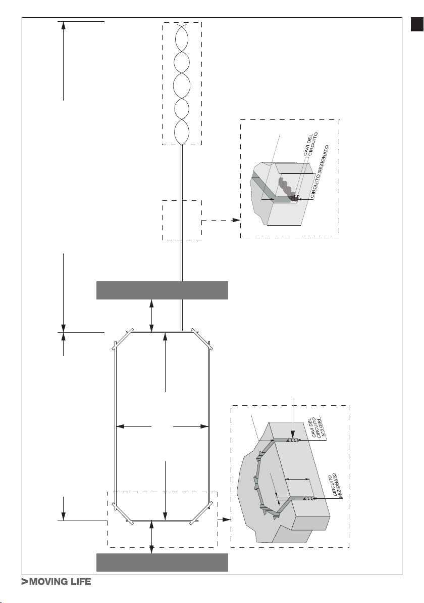
SIGILLANTE
IT
CIRCUITO DI USCITA
E IL CIRCUITO SENSIBILE
DISTANZA TRA L'ALIMENTATORE
CIRCUITO SENSIBILE
RITORCERE IL FILO
20-30 VOLTE/METRO
300 mm300 mm
Minimo 1 m
BORDO STRADA
SIGILLANTE
3 - 4 mm
Il cavo deve essere posizionato ordinatamente
in senso verticale ad ogni giro del circuito, non
deve accavallarsi.
3 - 5 cm
Profondità
CIRCUITO FINALE
BORDO STRADA
P-300SA1
CIRCUITO SENSIBILE
7
Page 8

TECHNICAL SPECIFICATIONS
Temperature range 0 °C - 60 °C
GB
Dimensions (SA1 board) 100 x 50 x 25 mm
Power supply 12 - 24V DC 40mA 16 - 24V AC 50mA
Loop setting time 5 seconds
Feeder cable length max. 50m with normal operation/100 m with reduced
sensitivity
FEATURES
• FILTER MODE: PROTECTS AGAINST FALSE TRIGGERING.
• OPEN LOOP AND SHORT-CIRCUIT DETECTION WITH FAULT WARNING BUZZER AND
LED.
• SENSITIVITY BOOST MODE FOR HIGH-BED TRUCKS AND TRAILERS.
• BEEPER FOR LOOP DETECTOR SETUP.
• LOOP FREQUENCY SELECTION
• PULSE OR PRESENCE OUTPUT
OPERATING CONDITIONS
- Crosstalk -
• Two loop detectors installed near each other can cause interference and false detections.
This problem can be eliminated or reduced by selecting different frequencies (DIP switch 1
ON=HIGH, OFF=LOW) and making sure you keep the loops at least 2 metres apart.
- Reinforcement -
• Reinforced steel under the loop detector (metal mesh under the road surface) can reduce
the detector’s sensitivity. In this case, you should add one or two additional turns of wire to
the loop.
INSTALLATION
- Loop wire -
• You are advised to use silicone-insulated wire measuring at least 1.5 mm in diameter with no
joints anywhere along its length.
• The sensing loop should have 3 turns of wire.
• The feeder should have at least 20-30 twists per metre, must be run separately from other
cables and must be as short as possible.
• If you are using the device to control exiting trafc, the loop should be positioned at least a
one and a half vehicle length from the barrier, gate or boom.
- Installing the loop -
• The slots cut into the road should be 3-5 cm deep.
• The sensing loop should be square or rectangular in shape, with the longest side covering
the width of the road and with the parallel sides of the loop set at least 1 m apart.
• Make a 45° crosscut across the corners of the rectangle to reduce the chance of the wire
being damaged.
• Run the wire in the slots made for the sensing loop (see section on “N° of turns of wire in the
sensing loop”) from the detection device and back, bearing in mind that the wire must have
at least 20-30 twists per metre for the exit loop. Twisting results in a reduction in the length
of the wire, hence you should leave a long enough tail of wire to start off with. The slot must
be wide enough to accommodate the suitably twisted wire.
• Once you have placed the wire in the bottom of the slots, use silicone or bitumen to securely
seal the wire in the slots so there is no chance of it moving.
WARNING: do not run the wire inside pipes or sheathes as this could reduce the
sensitivity of the magnetic eld generated.
8
P-300SA1
Page 9

NUMBER OF TURNS OF WIRE IN THE SENSING LOOP
• Perimeter of sensing loop < 7 m 4 turns
• Perimeter of sensing loop 7-10 m 3 turns
• Perimeter of sensing loop > 10 m 2 turns
In the event two loops are set alongside each other, use 3 turns of wire in one and 4 in the
other to avoid possible crosstalk.
Please be advised that there should be no joints in the wire used for the loop.
POSITION OF DETECTION DEVICE AND INSTALLATION
• Install the device in a watertight box.
• The detection device must be installed as near to the sensing loop as possible.
LOOP DETECTOR SETUP
Select the functions on the 9-way DIP switch.
Turn on power: after 5 seconds, the unit will beep and the red DL1 status LED will start ash-
ing.
The device will beep for the rst 10 detections
DipSwitch 1
DipSwitch
2 - 3
DipSwitch 4
ON
OFF
Sensitivity adjustment
OFF - OFF low
ON - OFF medium low
OFF - ON medium high
ON - ON high
ON detection boost option ACTIVE: when a truck is detected by the loop,
OFF detection boost option NOT ACTIVE
high frequency (see “Crosstalk” chap. “Operating conditions”);
low frequency (see “Crosstalk” chap. “Operating conditions”);
sensitivity is increased to its maximum level to detect trailers that are
high off the ground
GB
DipSwitch 5
DipSwitch 6
Relay activation in PRESENCE MODE (set with DIP switch 8)
ON PERMANENT PRESENCE mode: the relay stays on for as long as the
vehicle is detected by the sensing loop. Once the vehicle leaves the
detection area, the relay goes off.
OFF LIMITED PRESENCE mode: the relay activates when a vehicle is de-
tected and stays in this state for up to 30 min. If the vehicle fails to leave
the detection zone, a buzzer sounds after 25 minutes to indicate that
the relay will go off in another 5 min.
Relay activation in PULSE MODE (set with DIP switch 8)
ON ACTIVATE ON EXIT mode: The relay activates when the vehicle (or
metal object) leaves the detection area.
OFF ACTIVATE ON ENTRY mode: the relay activates when the vehicle (or
metal object) is detected.
P-300SA1
9
Page 10
GB
DipSwitch 7
DipSwitch 8
DipSwitch 9
RELAY STATE
Relay
PRESENCE
mode
PULSE
mode
ON FILTER ACTIVE: this setting determines a 2-second delay between
detecting the metal object and the relay activating. It can be used to
prevent false triggering due to small or fast objects moving through the
detection area or electric barriers nearby. If the object stays in the detection area for less than 2 seconds, the relay will not activate.
OFF FILTER NOT ACTIVE
Operating mode selection: this setting determines the relay’s reaction when the
vehicle (or metal object) is detected.
ON Activates PRESENCE mode (see DIP switch 5)
OFF Activates PULSE mode (see DIP switch 6)
The detection device must be reset every time the DIP switch settings are changed.
ON RESET: to reset, set DIP switch 9 to ON for approx. 2 sec., then switch
it back to OFF. The device is reset and the routine test is run on the
sensing loop.
OFF NORMAL
WARNING: When the setting of the DIP # 8 is changed, relay outputs vary, too (see
picture - page 28)
N.O.
(norm. open)
N.C.
(norm. closed)
N.O.
(norm. open)
N.C.
(norm. closed)
Vehicle
present
Vehicle
not
present
Closed Open Closed Closed
Open Closed Open Open
Closed for
1 sec.
Open for
1 sec.
Open Open Open
Closed Closed Closed
Fault
detection
circuit
Detection
device
not powered
During switch-on or reset:
make sure the detection area has been cleared of any bits of metal, tools and vehicles before switching on or resetting the detector!
TROUBLESHOOTING: CAUSES AND REMEDIES
Self-diagnostics on sensing loop:
Fault detection circuit – Loop open or frequency lower than 20 kHz
• FAULT LED (red LED): 3 ashes, 3-sec. pause, 3 ashes, 3-sec. pause…this sequence
continues until the loop is xed and the device is then reset.
• BUZZER: 3 beeps, 3-sec. pause, 3 beeps, 3-sec. pause…this sequence is repeated 5
times.
REMEDY: if there is no break in the loop, increase its frequency by adding more turns of wire
to the loop.
10
P-300SA1
Page 11

Fault detection circuit – Loop short-circuited or frequency higher than 120 kHz
• FAULT LED (red LED): 6 ashes, 3-sec. pause, 6 ashes, 3-sec. pause…this sequence
continues until the loop is xed and the device is then reset.
• BUZZER: 6 beeps, 3-sec. pause, 6 beeps, 3-sec. pause…this sequence is repeated 5
times.
REMEDY: if the loop has not short-circuited, decrease the loop’s frequency by reducing the
number of turns of wire in the loop.
Detection loop operating
• The STATUS LED (green), FAULT LED (red) and BUZZER will ash/beep (count) between
2 and 11 times to indicate the sensing loop’s operating frequency.
1 ash/beep (count) = 10 kHz.
Example: 3 ashes/beeps x 10 kHz = sensing loop frequency is 30 – 40 kHz.
LED AND BUZZER WARNINGS AFTER SWITCH-ON OR RESET
Status LED
Flashing at regular intervals No vehicle (metal object) detected
Steadily lit Vehicle (metal object) detected
Fault LED
3 ashes at 3-sec. intervals The loop is open. Fix it and reset.
6 ashes at 3-sec. intervals The loop has short-circuited. Fix it and reset.
BUZZER
Sounds for the full duration
of detection
Sounds when nothing
is detected
The buzzer will sound like this for the rst 10 detections.
Wires leaking to ground in the detection loop or on the power supply terminals. Fix them and reset.
GB
P-300SA1
11
Page 12

GB
SEALANT
CIRCUIT
WIRES
SECTIONIZED CIRCUIT
OUTPUT CIRCUIT
WIND THE WIRE
20-30 TIMES/METRE
DISTANCE BETWEEN THE POWER
SUPPLY AND THE SENSITIVE CIRCUIT
300 mm300 mm
SENSITIVE CIRCUIT
ROAD EDGE
Minimum 1 m
SEALANT
Each loop of wire must be neatly stacked, they
must not be allowed to get tangled.
WIRES
3 WINDS OF
THE CIRCUIT
3 - 5 cm
Depth
3 - 4 mm
FINAL CIRCUIT
CIRCUIT
SECTIONIZED
12
SENSITIVE CIRCUIT
ROAD EDGE
P-300SA1
Page 13

TECHNISCHE DATEN
Temperaturbereich 0 °C - 60 °C
Abmessungen (Karte SA1) 100 x 50 x 25 mm
Stromversorgung 12 – 24V DC 40 mA 16 – 24V AC 50 mA
Eingabezeit Kreislauf 5 Sekunden
Länge des Stromversorgungskabels max. 50 m Normale Funktionsweise / 100 m mit re-
duzierter Empndlichkeit
EIGENSCHAFTEN
• FILTERMODALITÄT: VERHINDERUNG FALSCHER AKTIVIERUNGEN
• ERFASSUNG OFFENER KREISLAUF UND KURZSCHLUSS MIT LED UND AKUSTISCHER DEFEKTANZEIGE.
• MODALITÄT ANHEBUNG DER EMPFINDLICHKEIT FÜR LASTWAGEN UND ANHÄNGER
MIT HEBEBÜHNE
• BIP FÜR DIE EINSTELLUNG DER ERFASSUNG
• AUSWAHL FREQUENZ KREISLAUF
• AUSGANG FÜR IMPULS ODER VORHANDENSEIN
BETRIEBSBEDINGUNGEN
- Interferenzen -
• Zwei nahe zusammen installierte Sensoren mit geschlossenem Kreislauf erzeugen Interferenzen und falsche Erfassungen. Dieser Mangel kann durch die Auswahl von verschiedenen
Frequenzen (DIP-Switch 1 ON = OBEN, OFF = UNTEN) sowie durch einen Mindestabstand
von 2 Metern zwischen den Kreisläufen behoben oder reduziert werden.
- Verstärkung -
• Der verstärkte Stahl unter dem Sensor mit geschlossenem Kreislauf (Metallgitter unter dem
Straßenbelag) kann die Empndlichkeit reduzieren. In diesem Fall müssen dem Kreislauf
eine oder zwei weitere Drahtschleifen hinzugefügt werden.
DE
INSTALLATION
- Draht des Kreislaufs -
• Wir empfehlen die Verwendung von Draht mit Silikonisolierung mit einem Mindestdurchmesser von 1,5 mm ohne Anschlüsse auf der gesamten Länge.
• Der empndliche Kreislauf sollte drei Kabelschleifen aufweisen.
• Der Abschnitt des Kreislaufs zwischen dem Netzteil und dem empndlichen Kreislauf sollte
zumindest 20 – 30 Mal pro Meter verdreht sein, muss separat von anderen Kabel verlaufen
und möglichst kurz sein.
• Im Fall der Verwendung einer Vorrichtung für die Regelung des ausgehenden Verkehrs sollte die Schleife mit einem Abstand von zumindest eineinhalb Fahrzeugen vom Tor oder von
der Schranke verlegt werden.
- Installation des Kreislaufs -
• Die in die Straße eingeschnittenen Kehlen sollten eine Tiefe von 3 – 5 cm aufweisen.
• Der empndliche Kreislauf sollte eine quadratische oder rechteckige Form aufweisen, mit
der längeren Seite zur Abdeckung der Breite der Straße sowie mit einem Mindestabstand
zwischen den parallelen Seite der Schleife von einem Meter.
• An den Ecken des Recktecks muss ein schräger Einschnitt mit 45° ausgeführt werden, um
mögliche Beschädigungen des Kabels zu verhindern.
• Das Kabel von der Erfassungsvorrichtung in den Kehlen des Erfassungskreislaufs (Siehe
Abschnitt “Anzahl der Kabelschleifen des empndlichen Kreislaufs) und zurück verlegen und
dabei berücksichtigen, dass das Kabel für den Ausgangskreislauf zumindest 20 – 30 Mal
pro Meter verdreht werden muss. Das Verdrehen führt zur einer Reduzierung der Länge des
Kabels und daher muss bereits von Anfang an überschüssiges Kabel eingeplant werden.
Die Kehle muss ausreichend breit für die Aufnahme des verdrehten Kabels sein.
P-300SA1
13
Page 14

• Nach dem Verlegen des Drahtes auf dem Boden der Kehlen muss es gut befestigt werden,
damit es sich nach dem Versiegeln mit Silikon oder Bitumen nicht bewegen kann.
ACHTUNG: Verlegen Sie das Kabel nicht in Rohren oder Mantelungen, um eine
DE
Reduzierung der Empndlichkeit des erzeugten Magnetfelds zu verhindern.
ANZAHL DER KABELSCHLEIFEN DES EMPFINDLICHEN KREISLAUFS
• Rand des empndlichen Kreislaufs < 7 m 4 Schleifen
• Rand des empndlichen Kreislaufs 7 – 10 m 3 Schleifen
• Rand des empndlichen Kreislaufs > 10 m 2 Schleifen
Falls zwei Kreisläufe nahe aneinander verlaufen, bei einem drei Kabelschleifen und beim
andren vier Kabelschleifen verwenden, um Interferenzen zu vermeiden.
Wir empfehlen, Anschlüsse im Kabel des Kreislaufs zu vermeiden.
POSITION DER ERFASSUNGSVORRICHTUNG UND INSTALLATION
• Installieren Sie die Vorrichtung in einem dichten Gehäuse.
• Die Erfassungsvorrichtung muss so nahe wie möglich am empndlichen Kreislauf installiert
werden.
EINSTELLUNG ERFASSUNG KREISLAUF
Wählen Sie Die Funktionen auf dem DIP-Switch mit 9 Wegen aus.
Strom anlegen: Nach 5 Sekunden ist ein Beep-Ton zu hören und die rote Status-LED DL1
beginnt zu blinken.
Die Vorrichtung sendet einen Beep-Ton für die ersten 10 Erfassungen
DipSwitch 1
DipSwitch
2 - 3
ON hohe Frequenz (siehe “Interferenzen” Kap. “Betriebsbedingungen”);
OFF niedrige Frequenz (siehe “Interferenzen” Kap. “Betriebsbedingungen”);
Einstellung der Empndlichkeit
OFF - OFF niedrig
ON - OFF mittel niedrig
OFF - ON mittel hoch
ON - ON hoch
DipSwitch 4
DipSwitch 5
DipSwitch 6
14
ON Auswahl angehobene Erfassung AKTIV: wenn ein Lastwagen vom
Kreislauf erfasst wird, wird die Empndlichkeit angehoben, um angehobene Anhänger zu erfassen
OFF Auswahl angehobene Erfassung NICHT AKTIV
Aktivierung des Relais in der MODALITÄT VORHANDENSEIN (Einstellung mit DIP 8)
ON Modalität PERMANENTES VORHANDENSEIN: das Relais bleibt aktiv,
solange des Fahrzeug vom empndlichen Kreislauf erfasst wird. Wenn
das Fahrzeug den Erfassungsbereich verlässt, wird das Relais deak-
tiviert.
OFF Modalität LIMITIERTES VORHANDENSEIN: das Relais wird bei der
Erfassung eines Fahrzeugs aktiviert und bleibt so für max. 30 Minuten.
Falls das Fahrzeug den Erfassungsbereich nicht verlässt, zeigt nach
25 Minuten ein akustisches Signal (Buzzer) an, dass das Relais in den
nächsten 5 Minuten deaktiviert wird.
Aktivierung des Relais in der MODALITÄT IMPULS (Einstellung mit DIP 8)
ON Modalität AKTIVIERUNG AUSGANG: das Relais wird aktiviert, wenn
das Fahrzeug (oder die metallische Masse) den Erfassungsbereich
verlässt.
OFF Modalität AKTIVIERUNG EINGANG: das Relais wird bei der Erfassung
des Fahrzeug (oder einer metallischen Masse) aktiviert.
P-300SA1
Page 15

ON FILTER AKTIV: diese Einstellung sieht eine Verzögerung von zwei Se-
kunden zwischen der Erfassung der metallischen Masse und der Aktivierung des Relais vor. Kann eingesetzt werden zur Verhinderung von
DipSwitch 7
falschen Aktivierungen durch kleine oder schnelle bewegliche Gegenstände im Erfassungsbereich oder elektrische Schranken in der Nähe.
Falls der Gegenstand weniger als zwei Sekunden im Erfassungsbereich bleibt, wird das Relais nicht erregt.
OFF FILTER NICHT AKTIVIERT
Auswahl der Betriebsweise: diese Einstellung bestimmt die Reaktion des Relais für
DipSwitch 8
die Erfassung des Fahrzeugs (oder der metallischen Masse).
ON Aktivierung Modalität VORHANDENSEIN (siehe DIP 5)
OFF Aktivierung Modalität IMPULS (siehe DIP 6)
Die Erfassungsvorrichtung muss jedes Mal zurückgestellt werden, wenn die Einstellungen der DIP-Switches geändert werden.
DipSwitch 9
ON RESET: Zur Rückstellung den DIP 9 für ca. zwei Sekunden auf ON und
dann erneut auf OFF setzen. Die Vorrichtung wird zurückgestellt und es
wird ein Routinetest des empndlichen Kreislaufs durchgeführt.
OFF NORMAL
VORSICHTIG: Durch die Einstellung des DIP-Schalters # 8 werden auch die Relais-
ausgänge neu programmiert (siehe Abbildung - Seite 28)
STATUS DES RELAIS
Relais
Modalität
VORHANDENSEIN
Modalität
IMPULS
N.O.
(Einschaltglied)
N.C.
(Ausschaltglied)
N.O.
(Einschaltglied)
N.C.
(Ausschaltglied)
Fahrzeug
vorhanden
Fahrzeug
nicht
vorhanden
geschlossen offen geschlossen geschlossen
offen geschlossen offen offen
geschlossen
für 1 Sekunde
offen
für 1 Sekunde
offen offen offen
geschlossen geschlossen geschlossen
Erfassungs-
kreislauf
defekt
DE
Erfassungs-
kreislauf nicht
gespeist
In der Einschalt- oder Resetphase:
Sicherstellen, dass der Erfassungsbereich frei von eventuellen Metallteilen, Werkzeugen und Fahrzeugen ist, bevor die Erfassung eingeschaltet oder neu einge-
stellt wird!
FUNKTIONSSTÖRUNGEN: URSACHEN UND BEHEBUNG
Auto-Diagnose des empndlichen Kreislaufs:
Erfassungskreislauf defekt – Kreislauf offen oder Frequenz unter 20 KHz
• FAULT LED (rote LED): 3 Mal Blinken, 3 Sekunden Pause, 3 Mal Blinken, 3 Sekunden
Pause... diese Sequenz wird fortgesetzt bis zur Berichtigung des Kreislaufs und zum nachfolgenden Reset der Vorrichtung.
• BUZZER: Drei Beep-Töne, drei Sekunden Pause, drei Beep-Töne, drei Sekunden Pause...
diese Sequenz wird 5 mal wiederholt.
BEHEBUNG: falls der Kreislauf nicht unterbrochen ist, die Frequenz anheben, indem Schleifen
hinzugefügt werden.
P-300SA1
15
Page 16

Erfassungskreislauf defekt – Kreislauf kurzgeschlossen oder Frequenz über 120 KHz
• FAULT LED (rote LED): 6 Mal Blinken, 3 Sekunden Pause, 6 Mal Blinken, 3 Sekunden
DE
Pause... diese Sequenz wird fortgesetzt bis zur Berichtigung des Kreislaufs und zum nachfolgenden Reset der Vorrichtung.
• BUZZER: 6 Beep-Töne, drei Sekunden Pause, 6 Beep-Töne, drei Sekunden Pause... diese
Sequenz wird 5 mal wiederholt.
BEHEBUNG: falls der Kreislauf nicht kurzgeschlossen ist, die Frequenz verringern, in den die
Anzahl der Schleifen verringert wird.
Erfassungskreislauf in Betrieb
• Die LED STATUS (grün), die LED FAULT (rot) und der BUZZER blinken/ertönen (Zählung)
zwischen zwei und 11 Mal, um die Betriebsfrequenz des empndlichen Kreislaufs anzuzei-
gen.
Ein Blinken/Beep-Ton (Zählung) = 10 KHz.
Beispiel: Drei Mal Blinken/Beep-Ton x 10 KHz = Frequenz des empndlichen Kreislaufs 30
40 KHz.
ANZEIGEN DER LEDS UND DES BUZZERS NACH DEM EINSCHALTEN ODER
DEM RESET
Status LED
Regelmäßiges Blinken Kein Fahrzeug (metallische Masse) erfasst
ununterbrochen an Fahrzeug (metallische Masse) erfasst
Fault LED
3 Mal Blinken mit Intervallen
von 3 Sekunden
6 Mal Blinken mit Intervallen
von 3 Sekunden
Der Kreislauf ist offen. Berichtigen und einen Reset vornehmen.
Der Kreislauf ist kurzgeschlossen. Berichtigen und einen
Reset vornehmen.
Akustisches Signal für die
gesamte Dauer der Erfassung
Akustisches Signal bei
fehlender Erfassung
16
BUZZER
Der Buzzer ertönt für die ersten 10 Erfassungen.
Kabel mit Verlusten im Erfassungskreislauf oder an den
Kontakten der Stromversorgung. Berichtigen und einen
Reset vornehmen.
P-300SA1
Page 17

DICHTUNGSMITTEL
DRÄHTE DES
KREISLAUFS
UNTERFLURKREISLAUF
DE
METER TWISTEN
AUSGANGSKREISLAUF
DRAHT 20-30 MAL PRO
GERÄT UND SCHALTKREIS
ABSTAND ZWISCHEN SPEISE-
300 mm300 mm
SCHALTKREIS
Minimum 1 m
FAHRBAHNRAND
DICHTUNGSMITTEL
3 - 4 mm
ENDKREISLAUF
Das Kabel muss ordentlich in vertikaler
Richtung verlegt werden und die einzelnen
Schleifen dürfen sich nicht überschneiden.
WINDUNGEN
DRÄHTE DES
KREISLAUFS NR. 3
3 - 5 cm
Tiefe
KREISLAUF
ABGESCHALTETER
SCHALTKREIS
FAHRBAHNRAND
P-300SA1
17
Page 18

SPECIFICATIONS TECHNIQUES
Échelle de température 0 °C – 60 °C
Dimensions (Fiche SA1) 100 x 50 x 25 mm
Alimentation 12 - 24V DC 40mA 16 – 24V AC 50mA
Temps de réglage circuit 5 secondes
FR
Longueur câble d’alimentation 50m Max. Fonctionnement normal/100m avec sen-
sibilité réduite
CARACTERISTIQUES
• MODALITE FILTRE : PREVENTION CONTRE DE FAUSSES ACTIVATIONS
• DETECTION CIRCUIT OUVERT OU COURT-CIRCUIT AVEC DELS ET SIGNAL SONORE
DE PANNE.
• MODALITE AUGMENTATION SENSIBILITE POUR CAMIONS ET CAMIONS DE DEPANNAGE AVEC PLATE-FORME ELEVEE.
• SIGNAL SONORE POUR REGLAGE DU DETECTEUR A CIRCUIT.
• SELECTION FREQUENCE CIRCUIT
• SORTIE POUR IMPULSION OU PRESENCE
CONDITIONS DE FONCTIONNEMENT
- Interférences -
• Deux capteurs à circuit fermé installés l’un à côté de l’autre provoquent des interférences
et de faux relevés. Cet inconvénient peut être éliminé ou réduit en sélectionnant des fréquences différentes (commutateur DIP 1 ON= HAUT, OFF=BAS) et sans espace inférieur à
2 mètres entre les circuits.
- Renforcement -
• L’acier renforcé sous le capteur à circuit fermé (lets métalliques sous le revêtement des
routes) peut réduire la sensibilité. Dans ce cas, il faudrait ajouter au circuit un ou deux tours
supplémentaires de l.
INSTALLATION
- Fil du circuit -
• Il est recommandé d’utiliser un l isolé au silicone de 1,5 mm de diamètre au minimum sans
jonction.
• Le circuit sensible devrait avoir 3 tours de câble.
• La portion de circuit entre alimentateur et circuit sensible doit être retors au moins 20 - 30
fois par mètre, il doit courir séparément des autres câbles et être le plus court possible.
• Si l’on utilise le dispositif pour la gestion du trac en sortie, la spire devrait être placée à une
distance au moins égale à la longueur d’un véhicule et 1/2 du portail, porte ou barrière.
- Installation du circuit -
• Les rainures incisées sur la route devraient avoir une profondeur de 3 - 5 cm.
• Le circuit sensible devrait être carré ou rectangulaire, avec le côté le plus long couvrant la
largeur de la route et la distance minimale entre les côtés parallèles de la spire est de 1 m.
• Il faut faire une coupure transversale aux angles du rectangle de 45°, pour réduire les possibilités d’endommagements du l.
• Faire courir le câble du dispositif de détection dans les rainures prévues pour le circuit sensible (voir par. «N° de tours du câble sur le circuit sensible) et retour, sans oublier que pour le
circuit de sortie le câbles doit être retors au moins 20 - 30 fois par mètre. La torsion entraîne
une réduction de la longueur du câble par conséquent, déjà au départ, laisser du câble en
plus. La rainure devra être sufsamment large pour contenir le câble retors correctement.
18
P-300SA1
Page 19

• Après avoir placé le l sur le fonds des rainures, il faut le xer fermement pour qu’il ne bouge
pas une fois scellé avec le silicone ou le bitume.
ATTENTION : ne pas faire passer le l à l’intérieur des tubes ou des gaines pour
éviter de réduire la sensibilité du champ magnétique produit.
NOMBRE DE TOURS DU CABLE SUR LE CIRCUIT SENSIBLE
• Périmètre circuit sensible < 7 m 4 tours
• Périmètre circuit sensible 7-10 m 3 tours
• Périmètre circuit sensible >10 m 2 tours
Si deux circuits sont adjacents, utiliser 3 tours de câble dans un et 4 dans l’autre pour
prévenir de possibles interférences.
Il est recommandé de ne pas faire de jointures sur le câble du circuit.
POSITION DU DISPOSITIF DE DETECTION ET INSTALLATION
• Installer le dispositif dans une boîte étanche.
• Le dispositif de détection doit être installé le plus prés possible du circuit sensible.
REGLAGE DU DETECTEUR A CIRCUIT
Sélectionner les fonctions sur le commutateur DIP à 9 voies.
Brancher : au bout de 5 secondes on entendra un signal sonore et la del rouge DL1 indiquant le «statut» commencera à clignoter.
Le dispositif enverra des signaux sonores pendant les 10 premières détections.
ON haute fréquence (voir «Interférences» chap. «Conditions de fonction-
DipSwitch 1
OFF basse fréquence (voir «Interférences» chap. «Conditions de fonction-
nement»);
nement»);
FR
DipSwitch
2 - 3
DipSwitch 4
DipSwitch 5
Réglage de la sensibilité
OFF - OFF basse
ON - OFF moyenne basse
OFF - ON moyenne haute
ON - ON haute
ON sélection détection augmentée ACTIVE : quand un camion est détecté
par le circuit, la sensibilité augmente au maximum pour relever les remorques hautes.
OFF sélection détection augmentée NON ACTIVE.
Activation du relais en MODALITE PRESENCE (réglage de DIP 8)
ON modalité PRESENCE PERMANENTE : le relais reste actif tant que le
véhicule est relevé par le circuit sensible. Quand le véhicule quitte la
zone de détection, le relais se désactive.
OFF modalité PRESENCE LIMTEE : le relais s’active à la détection d’un
véhicule et reste actif pendant 30 min maximum. Si le véhicule ne quitte
pas la zone de détection, au bout de 25 min, un signal sonore (sirène)
indique que le relais se désactivera après 5 minutes.
P-300SA1
19
Page 20

FR
Activation du relais en MODALITE IMPULSION (réglage de DIP 8)
ON modalité ACTIVATION EN SORTIE : le relais s’active quand le véhicule
DipSwitch 6
OFF modalité ACTIVATION EN ENTREE : le relais s’active à la détection du
(ou de la masse métallique) quitte la zone de détection.
véhicule (ou de la masse métallique).
ON FILTRE ACTIF : cette approche prévoit un retard de 2 secondes entre
la détection de la masse métallique et l’activation du relais. Il peut être
utilisé pour prévenir de fausses activations dues à des objets petits ou
DipSwitch 7
rapides en mouvement dans la zone de détection ou à des barrières
électriques à proximité. Si l’objet reste dans la zone de détection moins
de 2 secondes le relais ne sera pas activé.
OFF FILTRE NON ACTIF
Sélection modalité de fonctionnement : cette approche détermine la réaction du
DipSwitch 8
relais lors de la détection du véhicule (ou masse métallique).
ON Activation modalité PRESENCE (voir DIP 5)
OFF Activation modalité IMPULSION (voir DIP 6)
Le dispositif de détection doit être réglé à nouveau toutes les fois que les réglages
des commutateurs DIP changent.
DipSwitch 9
ON REINITIALISATION : pour régler, mettre le Dip 9 sur ON pendant 2
secondes environ, ensuite le mettre à nouveau sur OFF. Le dispositif
est réglé et le test de routine sera fait sur le circuit sensible.
OFF NORMAL
AVERTISSEMENT: si on change la position du dip-switch 8 varient également les
sorties du relais (voir schéma à page 28)
ETAT DU RELAIS
Circuit de
détection en
panne
Relais
Modalité
PRESENCE
Modalité
IMPULSION
N.O.
(norm. ouvert)
N.C.
(norm. fermé)
N.O.
(norm. ouvert)
N.C.
(norm. fermé)
Véhicule
présent
Fermé Ouvert Fermé Fermé
Ouvert Fermé Ouvert Ouvert
Fermé 1 sec. Ouvert Ouvert Ouvert
Ouvert 1 sec. Fermé Fermé Fermé
Véhicule non
présent
Lors de l’allumage ou réinitialisation :
s’assurer que la zone de détection ait été débarrassée d’éventuels morceaux de
métal, outils et véhicules avant d’allumer ou régler le détecteur !
20
P-300SA1
Dispositif de
détection non
alimenté
Page 21

DYSFONCTIONNEMENT CAUSES ET SOLUTIONS
Autodiagnostic
Circuit de détection panne - Circuit ouvert ou fréquence sous les 20 KHz
• FAULT LED (del rouge) : 3 clignotements, pause de 3 secondes, 3 clignotements, pause
de 3 secondes... et ainsi de suite jusqu’à la réinstallation du circuit et au réglage suivant du
dispositif.
• SIRENE : 3 signaux sonores, pause de 3 secondes, 3 signaux sonores, pause de 3 secondes...et ainsi de suite 5 fois.
REMEDES : si le circuit n’est pas interrompu, augmenter la fréquence en ajoutant plus de tours
de câble à la spire.
Circuit de détection panne - Court-circuit ou fréquence supérieur à 120 KHz
• FAULT LED (del rouge) : 6 clignotements, pause de 3 secondes, 6 clignotements, pause
de 3 secondes... et ainsi de suite jusqu’à la réinstallation du circuit et au réglage suivant du
dispositif.
• SIRENE : 6 signaux sonores, pause de 3 secondes, 6 signaux sonores, pause de 3 secondes...et ainsi de suite 5 fois.
REMEDES : s’il n’y a pas de court-circuit, diminuer la fréquence en réduisant les tours de câble
à la spire.
Circuit de détection fonctionnant
• Le STATUS DEL (verte), le FAULT DEL (rouge) et la SIRENE clignoteront/émettront un
signal (décompte) de 2 à 11 fois pour indiquer la fréquence de fonctionnement du circuit
sensible.
1 clignotement/signal (décompte) = 10KHz
Exemple : 3 clignotements/signaux x 10KHz = fréquence du circuit sensible de 30-40 KHz.
FR
INDICATIONS DES DELS ET DE LA SIRENE APRES L’ALLUMAGE OU LE REGLAGE
Status LED
Clignote régulièrement Aucun véhicule (masse métallique) détecté
Accès xe Véhicule (masse métallique) détecté
Fault LED
3 clignotements à intervalles
de 3 secondes
6 clignotements à intervalles
de 3 secondes
Signal sonore pendant toute
la durée de la détection
Signal sonore en absence
de détection
Le circuit est ouvert. Le réinstaller et faire un réglage.
Il y a un court-circuit. Le réinstaller et faire un réglage.
SIRENE
La sirène sonnera ainsi pendant les 10 premières détec-
tions.
Câbles en perte dans le circuit de détection ou sur les terminaux d’alimentation. Les réparer et faire un réglage.
P-300SA1
21
Page 22

FR
SCELLANT
FILS DU
CIRCUIT
CIRCUIT SECTIONNÉ
CIRCUIT DE SORTIE
ET LE CIRCUIT SENSIBLE
DISTANCE ENTRE L'ALIMENTATEUR
CIRCUIT SENSIBLE
RETORDRE LE FIL
20-30 FOIS PAR MÈTRE
300 mm300 mm
Minimum 1 m
FINAL CIRCUIT
BORD DE LA ROUTE
Le câble doit être placé soigneusement dans
les sens vertical de chaque tour du circuit, il ne
doit pas se chevaucher.
FILS DU
CIRCUIT
3 - 5 cm
Profondeur
N° 3 TOURS
CIRCUIT
SECTIONNÉ
SCELLANT
3 - 4 mm
22
CIRCUIT SENSIBLE
BORD DE LA ROUTE
P-300SA1
Page 23

ESPECIFICACIONES TÉCNICAS
Escala de temperatura 0 °C - 60 °C
Dimensiones (Tarjeta SA1) 100 x 50 x 25 mm
Alimentación 12 - 24V DC 40mA 16 – 24V AC 50mA
Tiempo de conguración lazo 5 segundos
Largo del cable de alimentación 50 m máx. Funcionamiento normal/100 m con sensi-
bilidad reducida
CARACTERÍSTICAS
• MODO FILTRO: PREVENCIÓN CONTRA FALSAS ACTIVACIONES.
• DETECCIÓN CIRCUITO ABIERTO Y CORTOCIRCUITO CON LED E INDICADOR ACÚSTICO DE AVERÍA.
• MODO INCRECMENTO SENSIBILIDAD PARA CAMIÓN Y REMOLQUE CON PLATAFORMA ELEVADA.
• SEÑAL SONORA PARA CONFIGURACIÓN DEL DETECTOR DE LAZO MAGNÉTICO.
• SELECCIÓN DE FRECUENCIA LAZO
• SALIDA PARA IMPULSO O PRESENCIA
CONDICIONES DE FUNCIONAMIENTO
- Interferencias -
• Dos detectores de lazo cerrado instalados uno cerca del otro provocan interferencias y una
detección falsa. Este inconveniente puede eliminarse o reducirse seleccionando frecuencias distintas (dipswitch 1 ON=ALTO, OFF=BAJO) y dejando un espacio no inferior a 2
metros entre ambos lazos.
- Refuerzo -
• El acero reforzado debajo del detector de lazo cerrado (mallas metálicas bajo la calzada)
puede reducir su sensibilidad. En tal caso se debería añadir al lazo una o dos espiras adicionales de cable.
ES
INSTALACIÓN
- Cable del lazo -
• Se recomienda usar cable aislado con silicona con un diámetro mínimo de 1,5 mm, sin empalmes en toda su extensión.
• El lazo detector debería tener 3 espiras de cable.
• El tramo de circuito entre el alimentador y el lazo detector debe estar trenzado al menos 20
- 30 vueltas por metro y debe instalarse separado de otros cables y ser lo más corto posible.
• En el caso de que se utilice el dispositivo para la gestión del tráco de salida, la espira debería situarse a una distancia equivalente al menos a la longitud de un vehículo y 1/2 desde
la puerta o barrera.
- Instalación del lazo -
• Las regatas hechas en el suelo deben tener una profundidad de 3 - 5 cm.
• El lazo detector debería tener una forma cuadrada o rectangular, con el lado largo que cubre
la anchura de la calle y una distancia mínima entre los lados paralelos de la espira de 1 m.
• En los ángulos del rectángulo hay que hacer un corte transversal de 45°, para reducir las
posibilidades de dañar el cable.
• Tender el cable desde el dispositivo detector en las regatas hechas para el lazo (véase § “N°
de espiras del cable del lazo detector) y su retorno, teniendo en cuenta que para el circuito
de salida el cable debe tener un trenzado con al menos 20 - 30 vueltas por metro. El trenzado implica una reducción de la longitud del cable, por lo que ya desde el comienzo hay
que considerar un cable más largo. La regata deberá ser lo bastante ancha para contener
el cable trenzado.
P-300SA1
23
Page 24

• Tras introducir el cable en el fondo de la regata habría que jarlo rmemente a la misma a
n de que no pueda moverse una vez sellado con silicona o betún asfáltico.
ATENCIÓN: no introduzca el cable dentro de tubos o recubrimientos para no reducir la sensibilidad del campo magnético generado.
NÚMERO DE ESPIRAS DEL CABLE EN EL LAZO DETECTOR
ES
• Perímetro lazo detector < 7 m 4 espiras
• Perímetro lazo detector 7-10 m 3 espiras
• Perímetro lazo detector > 10 m 2 espiras
En el caso en que dos lazos estén adyacentes uno al otro, utilice 3 espiras de cable en
uno y 4 en el otro para prevenir posibles interferencias.
Se recomienda no realizar empalmes en el cable del lazo.
POSICIÓN DEL DISPOSITIVO DETECTOR E INSTALACIÓN
• Instale el dispositivo en una caja hermética.
• El dispositivo detector debe instalarse lo más cerca posible del lazo.
CONFIGURACIÓN DETECTOR DE LAZO
Seleccionar las funciones en el dipswitch de 9 vías.
Conectar la corriente: transcurridos 5 segundos se oirá un tono de aviso y el led rojo DL1
que indica el “estado” comenzará a destellar.
El dispositivo enviará unos tonos de aviso para las 10 primeras detecciones.
ON alta frecuencia (véase “Interferencias” cap. “Condiciones de funciona-
DipSwitch 1
OFF baja frecuencia (véase “Interferencias” cap. “Condiciones de funciona-
miento”);
miento”);
DipSwitch
2 - 3
DipSwitch 4
DipSwitch 5
24
Ajuste de la sensibilidad
OFF - OFF baja
ON - OFF medio baja
OFF - ON medio alta
ON - ON alta
ON selección incremento detección ACTIVA: cuando el lazo detecta un ca-
mión aumenta la sensibilidad al máximo para detectar los remolques
elevados del suelo
OFF selección incremento detección NO ACTIVA
Activación del relé en MODO PRESENCIA (ajuste desde DIP 8)
ON modo PRESENCIA PERMANENTE: el relé queda activo hasta que el
vehículo es detectado por el lazo. Cuando el vehículo deja el área de
detección, el relé se desactiva.
OFF modo PRESENCIA LIMITADA: el relé se activa al detectar el tránsito
de un vehículo y queda así durante un máx. de 30 min. Si el vehículo
no sala del área de detección transcurridos 25 min una señal acústica
(zumbador) indica que el relé se desactivará después de los 5 min.
siguientes.
P-300SA1
Page 25

Activación del relé en MODO IMPULSIVO (ajuste desde DIP 8)
ON modo ACTIVACIÓN SALIDA: el relé se activa cuando el vehículo (o
DipSwitch 6
OFF modo ACTIVACIÓN ENTRADA: el relé se activa al detectar el vehículo
masa metálica) abandona el área de detección.
(o masa metálica).
ON FILTRO ACTIVO: este ajuste prevé un retardo de 2 seg entre la detec-
ción de la masa metálica y la activación del relé. Puede utilizarse para
prevenir falsas activaciones debidas a objetos pequeños o veloces que
DipSwitch 7
se mueven en el área de detección o a barreras eléctricas en las cercanías. Si el objeto queda en el área de detección durante menos de 2
seg el relé no se activará.
OFF FILTRO NO ACTIVO
Selección modo de funcionamiento: este ajuste determina la reacción del relé a la
DipSwitch 8
detección del vehículo (o masa metálica).
ON Activación modo PRESENCIA (véase DIP 5)
OFF Activación modo IMPULSIVO (véase DIP 6)
El dispositivo de detección debe reajustarse cada vez que se cambien las conguraciones de los dip-switches.
DipSwitch 9
ON RESET: para reajustar, ponga el Dip 9 en ON durante unos 2 seg, en-
tonces póngalo de nuevo en OFF. El dispositivo se reajusta y se hace
el ensayo de rutina en el lazo detector.
OFF NORMAL
ATENCIÓN: Cambiando la posición del DIP # 8 también cambian las salidas de los
relés (ver imagen - pagina 28)
ES
ESTADO DEL RELÉ
Vehículo
no
presente
Abierto Abierto Abierto
Cerrado Cerrado Cerrado
Relé
Modo
PRESENCIA
Modo
IMPULSIVO
N.O.
(norm. abierto)
N.C.
(norm. cerrado)
N.O.
(norm. abierto)
N.C.
(norm. cerrado)
Vehículo
presente
Cerrado Abierto Cerrado Cerrado
Abierto Cerrado Abierto Abierto
Cerrado
durante 1 seg
Abierto
durante 1 seg
Durante el encendido o reset:
asegúrese de que hayan sido retirados los trozos de metal, herramientas y vehícu-
los del área de detección antes de encender o recongurar el detector
P-300SA1
Lazo
detección
averiado
Dispositivo
detector
no
alimentado
25
Page 26

PROBLEMAS DE FUNCIONAMIENTO: CAUSAS Y SOLUCIONES
Auto-diagnóstico en el lazo detector:
Lazo de detección averiado - Circuito abierto o frecuencia por debajo de 20 KHz
• FAULT LED (led rojo): 3 destellos, 3 seg de pausa, 3 destellos, 3 seg de pausa... esta se-
ES
cuencia prosigue hasta que se arregla el circuito y el se hace el reset del dispositivo.
• ZUMBADOR: 3 tonos de aviso, 3 seg de pausa, 3 tonos de aviso, 3 seg de pausa... esta
secuencia se repite 5 veces.
SOLUCIÓN: si el circuito no está interrumpido, aumente la frecuencia del lazo añadiendo algunas vueltas de cable en la espira.
Lazo detección averiado - Circuito abierto o frecuencia por encima de 120 KHz
• FAULT LED (led rojo): 6 destellos, 3 seg de pausa, 6 destellos, 3 seg de pausa... esta secuencia prosigue hasta que se arregla el circuito y el se hace el reset del dispositivo.
• ZUMBADOR: 6 tonos de aviso, 3 seg de pausa, 6 tonos de aviso, 3 seg de pausa... esta
secuencia se repite 5 veces.
SOLUCIÓN: si no está en cortocircuito, disminuya la frecuencia del lazo reduciendo las vueltas
de cable de la espira.
Lazo de detección en funcionamiento
• El STATUS LED (verde), el FAULT LED (rojo) y el ZUMBADOR destellan/suenan (conteo)
entre 2 y 11 veces para indicar la frecuencia de funcionamiento del lazo.
1 destello/tono aviso (conteo) = 10 KHz.
Ejemplo: 3 destellos/tonos aviso x 10 KHz = frecuencia del lazo de 30 - 40 KHz.
INDICACIONES DE LOS LEDS Y DEL ZUMBADOR DESPUÉS DEL ENCENDIDO
O EL RESET
Status LED
Destella regularmente Ningún vehículo (masa metálica) detectado
Encendido jo Vehículo (masa metálica) detectado
Fault LED
3 Destellos con
intervalos de 3 seg.
6 Destellos con
intervalos de 3 seg.
Señal acústica durante
toda la detección
Señal acústica en caso
de ausencia de detección
26
El circuito está abierto. Repárelo y haga un reset.
Está en cortocircuito. Repárelo y haga un reset.
ZUMBADOR
El zumbador sonará así durante las 10 primeras deteccio-
nes.
Cables con pérdida en el lazo de detección o en los terminales de alimentación. Repárelos y haga un reset.
P-300SA1
Page 27

SELLANTE
HILOS DEL
CIRCUITO
CIRCUITO SECCIONADO
ES
CIRCUITO DE SALIDA
Y EL CIRCUITO SENSIBLE
DISTANCIA ENTRE EL ALIMENTADOR
CIRCUITO SENSIBLE
RETORCER EL HILO
20-30 VECES/METRO
300 mm300 mm
Minimo 1 m
CIRCUITO FINAL
BORDE DE LA CARRETERA
El cable debe colocarse de forma ordenada en
sentido vertical en cada vuelta del lazo, no
debe superponerse.
HILOS DEL
3 VUELTAS
3 - 5 cm
Profundidad
CIRCUITO CON
CIRCUITO
SECCIONADO
SELLANTE
3 - 4 mm
P-300SA1
CIRCUITO SENSIBLE
BORDE DE LA CARRETERA
27
Page 28

7ED
7BD
'"6-5-&%3&%
45"564-&%(3&&/
.%
0/
HI FREQUENCY
0''
-001
LO FREQUENCY
ON
1 2 3 4 5 6 7 8 9
7
LOW LOW/MED MED/HIGH HIGH
.0%&
/0
16-4&
.0%&
/$
13&4&/$&
3&-":065165
%*148*5$)
LIMITED PRESENCE PERM PRESENCE
NORMAL BOOST
/$
$0.
/0
$0.
DETECT PULSE UNDETECTED PULSE
NORMAL FILTER
PULSE PRESENT
NORMAL RESET
28
P-300SA1
Page 29

DICHIARAZIONE DI CONFORMITA’ DECLARATION OF CONFORMITY KONFORMITÄTSERKLÄRUNG
(ai sensi della Direttiva Europea 2006/42/CE AlI. II.A) (European Directive 2006/42/CE All. Il.A) (gemäß der Europäischen Richtlinie 2006/42/CE Anl. Il.A)
DECLARATlON DE CONFORMITY DECLARACIÓN DE CONFORMIDAD
(aux termes de la Directive européenne 2006/42/CE All. II.A) (según la Directiva Europea 2006/42/CE Anex. Il.A)
Fabbricante / Manufacturer / Hersteller / Fabricant / Fabricante: TAU s.r.l.
Indirizzo / Address / Adresse / Adresse / Dirección: Via E. Fermi, 43
36066 - Sandrigo
VICENZA - ITALY
Dichiara sotto la propria responsabilità che il prodotto: / Declares under its own responsibility that the following
product: / Erklärt auf eigene Verantwortung, daß das Produkte: / Déclare sous sa propre responsabilté que le produit:
/ Declara, bajo su propria responsabilidad, que el producto:
Rilevatore spira magnetica / Inductive loop detector / Magnetspulendetektor / Detecteur a spire
magnetique / Detector espira magnética
P-300SA1
è conforme ai requisiti essenziali di sicurezza delle direttive: / comply with the main safety requirements of the
follwing Directives: / entsprechen den grundlegenden Sicherheitsbedingungen der Direktiven: / il est conforme aux
exigences essentielles de sécurité de la Directive: / cumple con los requisitos esenciales de seguridad de la Directiva:
- 2006/95/EC Low Voltage Directive
- 2004/108/EC Electromagnetic Compatibility Directive
Sandrigo, 11/11/2011
Il Rappresentante Legale / The legal Representative
Der gesetzliche Vertreter / Le Représentant Légal
El Representante Legal
_________________________________________
Loris Virgilio Danieli
Nome e indirizzo della persona autorizzata a costituire la documentazione tecnica pertinente / Name and address
of person authorised to draw up all pertinent technical documentation / Name und Adresse der beauftragten Person
zur Vorlegung der zugehörigen technischen Unterlagen / Nom et adresse de la personne autorisée à constituer la
documentation technique pertinente / Nombre y dirección de la persona autorizada a entregar la documentación
técnica pertinente:
Loris Virgilio Danieli - via E. Fermi, 43 - 36066 Sandrigo (Vi) Italia
P-300SA1
29
Page 30

Page 31

Page 32

Via Enrico Fermi, 43
36066 Sandrigo (VI) - Italy
Tel +39 0444 750190
Fax +39 0444 750376
info@tauitalia.com
www.tauitalia.com
 Loading...